SECTION 702 DIVISION 700 - MATERIALS - NH.gov
28
SECTION 702 DIVISION 700 - MATERIALS SECTION 702 -- BITUMINOUS MATERIALS Table 2 -- Anionic Asphalt Emulsion (English) Type Rapid-Setting Grade RS-1 RS-2 HFMS-2 MS-4 MS-5 min max min max min max min max min max Tests on emulsions: Viscosity, Saybolt Furol 20 100 100 50 500 50 500 at 77 F, s see (1) Viscosity, Saybolt Furol 75 400 at 122 F, s Storage stability test, 24-h, % 1 1 1 1 1 Coating ability and water resistance: Coating, dry aggregate good 75+ 75+ Coating, after spraying fair see (2) (3) (4) see (2) (3) (4) Coating, wet aggregate fair Coating, after spraying fair Sieve test, % 0.10 0.10 0.10 0.10 0.10 Oil Distillate, % 2.0 7.0 0 3.0 Residue by distillation, % 55 63 65 65 65 Tests on residue from distillation test: Penetration, 77 F, 100 200 100 200 100 200 200 150 250 100 g, 5 s Solubility in trichloroethylene, % 97.5 97.5 97.5 97.5 97.5 Float test, 140 F, s 1200 50 100 Table 2E -- Anionic Asphalt Emulsion (Metric) Type Rapid-Setting Grade RS-1 RS-2 HFMS-2 MS-4 MS-5 min max min max min max min max min max Tests on emulsions: Viscosity, Saybolt Furol 20 100 100 50 500 50 500 at 25 C, s see (1) Viscosity, Saybolt Furol 75 400 at 50 C, s Storage stability test, 24-h, % 1 1 1 1 1 Coating ability and water resistance: Coating, dry aggregate good 75+ 75+ Coating, after spraying fair see (2) (3) (4) see (2) (3) (4) Coating, wet aggregate fair Coating, after spraying fair Sieve test, % 0.10 0.10 0.10 0.10 0.10 Oil Distillate, % 2.0 7.0 0 3.0 Residue by distillation, % 55 63 65 65 65 Tests on residue from distillation test: Penetration, 25 C, 100 200 100 200 100 200 200 150 250 100 g, 5 s Solubility in trichloroethylene, % 97.5 97.5 97.5 97.5 97.5 Float test, 60 C, s 1200 50 100 Numbers in parenthesis refer to notes on page 7-2. New Hampshire Department of Transportation Standard Specifications – 2010 7-1
Transcript of SECTION 702 DIVISION 700 - MATERIALS - NH.gov

SECTION 702
DIVISION 700 - MATERIALS
SECTION 702 -- BITUMINOUS MATERIALS
Table 2 -- Anionic Asphalt Emulsion (English)
Type Rapid-Setting
Grade RS-1 RS-2 HFMS-2 MS-4 MS-5
min max min max min max min max min max
Tests on emulsions:
Viscosity, Saybolt Furol 20 100 100 50 500 50 500
at 77 F, s see (1)
Viscosity, Saybolt Furol 75 400
at 122 F, s
Storage stability test, 24-h, % 1 1 1 1 1
Coating ability and water
resistance:
Coating, dry aggregate good 75+ 75+
Coating, after spraying fair see (2) (3) (4) see (2) (3) (4)
Coating, wet aggregate fair
Coating, after spraying fair
Sieve test, % 0.10 0.10 0.10 0.10 0.10
Oil Distillate, % 2.0 7.0 0 3.0
Residue by distillation, % 55 63 65 65 65
Tests on residue from distillation test:
Penetration, 77 F, 100 200 100 200 100 200 200 150 250
100 g, 5 s
Solubility in trichloroethylene, % 97.5 97.5 97.5 97.5 97.5
Float test, 140 F, s 1200 50 100
Table 2E -- Anionic Asphalt Emulsion (Metric)
Type Rapid-Setting
Grade RS-1 RS-2 HFMS-2 MS-4 MS-5
min max min max min max min max min max
Tests on emulsions:
Viscosity, Saybolt Furol 20 100 100 50 500 50 500
at 25 C, s see (1)
Viscosity, Saybolt Furol 75 400
at 50 C, s
Storage stability test, 24-h, % 1 1 1 1 1
Coating ability and water
resistance:
Coating, dry aggregate good 75+ 75+
Coating, after spraying fair see (2) (3) (4) see (2) (3) (4)
Coating, wet aggregate fair
Coating, after spraying fair
Sieve test, % 0.10 0.10 0.10 0.10 0.10
Oil Distillate, % 2.0 7.0 0 3.0
Residue by distillation, % 55 63 65 65 65
Tests on residue from distillation test:
Penetration, 25 C, 100 200 100 200 100 200 200 150 250
100 g, 5 s
Solubility in trichloroethylene, % 97.5 97.5 97.5 97.5 97.5
Float test, 60 C, s 1200 50 100
Numbers in parenthesis refer to notes on page 7-2.
New Hampshire Department of Transportation
Standard Specifications – 2010
7-1

SECTION 702
TABLE 2 -- ANIONIC ASPHALT EMULSIONS (continued)
(1) 50 + when material is used for sealing.
(2) Wet Coating: Weigh 100 ± 0.5 g of aggregate, 20 to 30 mesh (0.85 to 0.60 mm) standard Ottawa sand, into a 600 mL
glass beaker and add soft tap water, approximately twice the volume of that of sand. Weigh into the beaker containing
the sand and water 8 ± 0.2 g of the emulsion at room temperature and mix for two minutes with a stiff spatula. Cover the
mixture with approximately twice its own volume of tap water and pour the water off without further mixing. Repeat this
process. After the second rinse, at least 75 percent of the sand shall remain coated.
(3) Stripping: After evaluating the wet coating, place the mixture into a clear 600 mL glass beaker, cover the mixture with
tap water, let stand for 12 to 16 hours, and examine. At least 75 percent of the sand shall remain coated.
(4) The coating and stripping tests may be waived when MS-5 is used for sand sealing.
New Hampshire Department of Transportation
Standard Specifications – 2010
7-2

--- --- --- --- --- ---
--- --- --- ---
--- --- --- ---
--- --- ---
--- --- ---
--- --- ---
--- ---
---
--- --- ---
--- --- --- --- --- ---
--- --- --- --- --- ---
--- --- --- --- --- ---
--- --- --- ---
--- --- --- ---
--- --- ---
--- --- ---
--- --- ---
--- ---
---
--- --- ---
--- --- --- --- --- ---
--- --- --- --- --- ---
SECTION 703
SECTION 703 – AGGREGATES
Table 1E -- Required Grading, Graded Coarse Aggregates (English)
Standard
Stone Size #4 #357 #467 #57 #67 #7 #89
Min to 3/4 in to No. 4 No. 4 No. 4 No. 4 No. 4 No. 16
Max 1-1/2 in to 2 in to 1-1/2 in to 1 in to 3/4 in to 1/2 in to 3/8 in
Sieve
Size Percentage by Weight Passing
2-1/2 in 100
2 in 100 95-100 100
1-1/2 in 90-100 95-100 100
1 in 20-55 35-70 95-100 100
3/4 in 0-15 35-70 90-100 100
1/2 in 10-30 25-60 90-100 100
3/8 in 0-5 10-30 20-55 40-70 90-100
No. 4 0-5 0-5 0-10 0-10 0-15 20-55
No. 8 0-5 0-5 0-5 5-30
No. 16 0-10
No. 50 0-5
Table 1M -- Required Grading, Graded Coarse Aggregates (Metric)
Standard
Stone Size #4 #357 #467 #57 #67 #7 #89
Min to 19.0 to 4.75 to 4.75 to 4.75 to 4.75 to 4.75 to 1.18 to
Max, mm 37.5 50 37.5 25.0 19.0 12.5 9.5
Sieve
Size Percentage by Weight Passing
63 mm 100
50 mm 100 95-100 100
37.5 mm 90-100 95-100 100
25.0 mm 20-55 35-70 95-100 100
19.0 mm 0-15 35-70 90-100 100
12.5 mm 10-30 25-60 90-100 100
9.5 mm 0-5 10-30 20-55 40-70 90-100
4.75 mm 0-5 0-5 0-10 0-10 0-15 20-55
2.36 mm 0-5 0-5 0-5 5-30
1.18 mm 0-10
0.300 mm 0-5
New Hampshire Department of Transportation
Standard Specifications – 2010
7-3
SECTION 707
SECTION 707 -- CEMENT MORTAR
Description
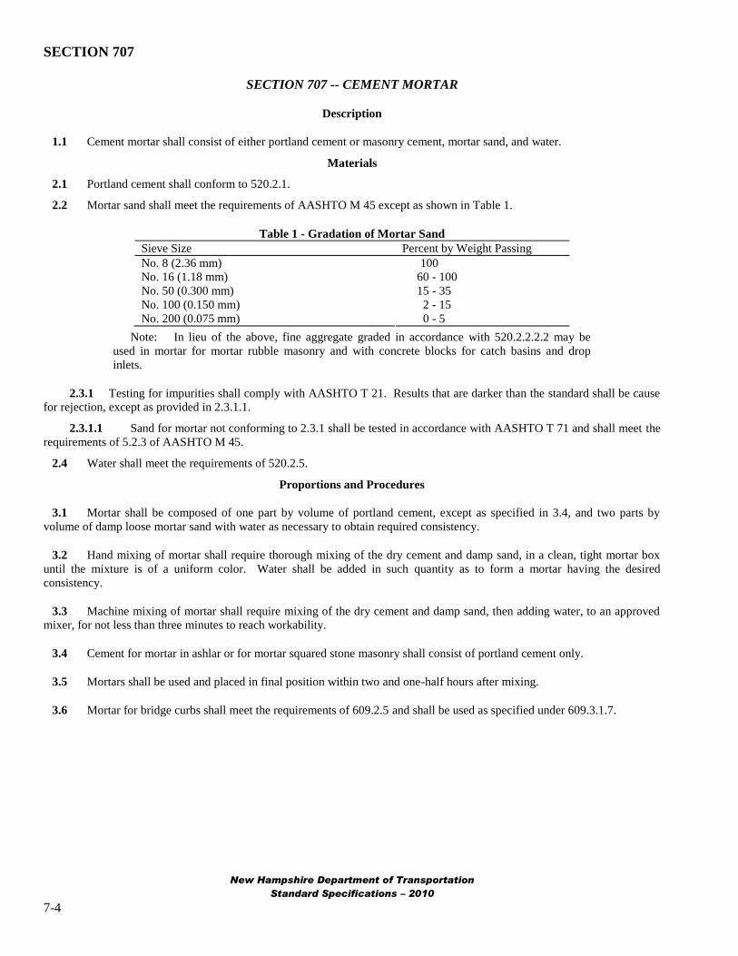
1.1 Cement mortar shall consist of either portland cement or masonry cement, mortar sand, and water.
Materials
2.1 Portland cement shall conform to 520.2.1.
2.2 Mortar sand shall meet the requirements of AASHTO M 45 except as shown in Table 1.
Table 1 - Gradation of Mortar Sand
Sieve Size Percent by Weight Passing
No. 8 (2.36 mm) 100
No. 16 (1.18 mm) 60 - 100
No. 50 (0.300 mm) 15 - 35
No. 100 (0.150 mm) 2 - 15
No. 200 (0.075 mm) 0 - 5
Note: In lieu of the above, fine aggregate graded in accordance with 520.2.2.2.2 may be
used in mortar for mortar rubble masonry and with concrete blocks for catch basins and drop
inlets.
2.3.1 Testing for impurities shall comply with AASHTO T 21. Results that are darker than the standard shall be cause
for rejection, except as provided in 2.3.1.1.
2.3.1.1 Sand for mortar not conforming to 2.3.1 shall be tested in accordance with AASHTO T 71 and shall meet the
requirements of 5.2.3 of AASHTO M 45.
2.4 Water shall meet the requirements of 520.2.5.
Proportions and Procedures
3.1 Mortar shall be composed of one part by volume of portland cement, except as specified in 3.4, and two parts by
volume of damp loose mortar sand with water as necessary to obtain required consistency.
3.2 Hand mixing of mortar shall require thorough mixing of the dry cement and damp sand, in a clean, tight mortar box
until the mixture is of a uniform color. Water shall be added in such quantity as to form a mortar having the desired
consistency.
3.3 Machine mixing of mortar shall require mixing of the dry cement and damp sand, then adding water, to an approved
mixer, for not less than three minutes to reach workability.
3.4 Cement for mortar in ashlar or for mortar squared stone masonry shall consist of portland cement only.
3.5 Mortars shall be used and placed in final position within two and one-half hours after mixing.
3.6 Mortar for bridge curbs shall meet the requirements of 609.2.5 and shall be used as specified under 609.3.1.7.
New Hampshire Department of Transportation
Standard Specifications – 2010
7-4
SECTION 708
SECTION 708 -- PAINTS
708.01 Description. These specifications are intended to specify paints that will meet service requirements for highway
construction.
Paint shall be homogeneous, free of contaminant, and of a consistency suitable for use in the capacity for which it is
specified. Finished paint shall be well ground, and the pigment shall be properly dispersed in the vehicle according to the
requirements of the paint. The dispersion shall be of such nature that the pigment does not settle, does not cake or thicken in
the container, and does not become granular or curdled. The paint shall be easily broken up with a paddle to form a smooth
uniform product of the proper consistency and shall possess satisfactory properties in all respects which affect its application
and curing.
The color shall match the established standard. The hiding power shall be sufficient to obtain complete hiding of the
preceding coat with a single application when applied at normal spreading rates. The finish coat shall dry to a semi gloss
finish, unless specified otherwise.
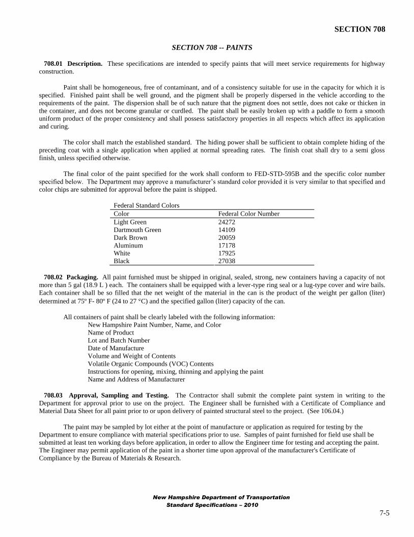
The final color of the paint specified for the work shall conform to FED-STD-595B and the specific color number
specified below. The Department may approve a manufacturer‟s standard color provided it is very similar to that specified and
color chips are submitted for approval before the paint is shipped.
Federal Standard Colors
Color Federal Color Number
Light Green 24272
Dartmouth Green 14109
Dark Brown 20059
Aluminum 17178
White 17925
Black 27038
708.02 Packaging. All paint furnished must be shipped in original, sealed, strong, new containers having a capacity of not
more than 5 gal (18.9 L ) each. The containers shall be equipped with a lever-type ring seal or a lug-type cover and wire bails.
Each container shall be so filled that the net weight of the material in the can is the product of the weight per gallon (liter)
determined at 75º F- 80º F (24 to 27 C) and the specified gallon (liter) capacity of the can.
All containers of paint shall be clearly labeled with the following information:
New Hampshire Paint Number, Name, and Color
Name of Product
Lot and Batch Number
Date of Manufacture
Volume and Weight of Contents
Volatile Organic Compounds (VOC) Contents
Instructions for opening, mixing, thinning and applying the paint
Name and Address of Manufacturer
708.03 Approval, Sampling and Testing. The Contractor shall submit the complete paint system in writing to the
Department for approval prior to use on the project. The Engineer shall be furnished with a Certificate of Compliance and
Material Data Sheet for all paint prior to or upon delivery of painted structural steel to the project. (See 106.04.)
The paint may be sampled by lot either at the point of manufacture or application as required for testing by the
Department to ensure compliance with material specifications prior to use. Samples of paint furnished for field use shall be
submitted at least ten working days before application, in order to allow the Engineer time for testing and accepting the paint.
The Engineer may permit application of the paint in a shorter time upon approval of the manufacturer's Certificate of
Compliance by the Bureau of Materials & Research.
New Hampshire Department of Transportation
Standard Specifications – 2010
7-5
SECTION 708
Unless otherwise provided, the materials entering into the composition of the paint shall conform to the requirements
of the applicable ASTM and AASHTO standards and FSS covering such materials. Testing shall be in accordance with the
latest test methods of the ASTM and AASHTO. However, the Department reserves the right to make use of any information or
methods of testing to determine the quality of paint and paint materials.
708.05 Traffic Paint Identification. To provide a means of identification, the applicable number and name taken from the
following list, unless otherwise specified, shall be printed on the label.
Traffic Paints
NH 4.11 White Bead Binder
NH 4.12 Yellow Bead Binder
1.1 General. This specification describes ready-mixed traffic markings that shall be used as a base for reflective beads , or
for use as a plain non-reflective marking. The marking shall be suitable for either bituminous or concrete surfaces.
1.2 The paint shall be formulated and processed specifically for service as a binder for reflective beads, in such a manner
as to produce maximum adhesion, refraction, and retroreflection. Any capillary action of the paint shall not be such as to cause
complete coverage of the beads.
1.3 The paint shall be well mixed in the manufacturing process and shall be properly ground when incorporating the
pigments in order to conform to the requirements as specified.
1.4 The paint shall not liver, thicken, curdle, gel, or otherwise show any objectionable properties during storage and
shall be readily remixed manually to a smooth uniform consistency throughout.
1.5 The paint shall dry on a road surface to a uniform noncracking film that will not darken in sunlight. It shall be
formulated for application with mechanical line-marking equipment and shall meet the opacity (contrast ratio) properties
specified herein. The paint is a substrate for binding glass beads so as to produce a highly weather resistant traffic line.
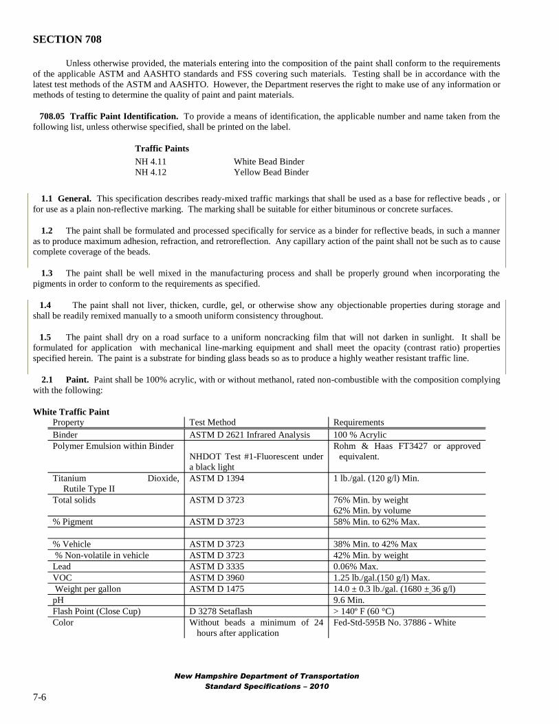
2.1 Paint. Paint shall be 100% acrylic, with or without methanol, rated non-combustible with the composition complying
with the following:
White Traffic Paint
Property Test Method Requirements
Binder ASTM D 2621 Infrared Analysis 100 % Acrylic
Polymer Emulsion within Binder Rohm & Haas FT3427 or approved
NHDOT Test #1-Fluorescent under equivalent.
a black light
Titanium Dioxide,
Rutile Type II
ASTM D 1394 1 lb./gal. (120 g/l) Min.
Total solids ASTM D 3723 76% Min. by weight
62% Min. by volume
% Pigment ASTM D 3723 58% Min. to 62% Max.
% Vehicle ASTM D 3723 38% Min. to 42% Max
% Non-volatile in vehicle ASTM D 3723 42% Min. by weight
Lead ASTM D 3335 0.06% Max.
VOC ASTM D 3960 1.25 lb./gal.(150 g/l) Max.
Weight per gallon ASTM D 1475 14.0 ± 0.3 lb./gal. (1680 ± 36 g/l)
pH 9.6 Min.
Flash Point (Close Cup) D 3278 Setaflash > 140º F (60 °C)
Color Without beads a minimum of 24
hours after application
Fed-Std-595B No. 37886 - White
New Hampshire Department of Transportation
Standard Specifications – 2010
7-6

SECTION 708
Yellow Traffic Paint
Property Test Method Requirements
Binder ASTM D 2621 Infrared Analysis 100 % Acrylic
Polymer Emulsion within Binder NHDOT Test 1 – Florescent under Rohm and Haas FT3427 or approved
black light equivalent.
Pigment - Yellow #65 or #75
Titanium Dioxide, ASTM D 1394 0.2 lb./gal.(24 g/l) Min.
Rutile Type II
Total solids ASTM D 3723 76% Min. by weight
62% Min. by volume
% Pigment ASTM D 3723 58% Min. to 62% Max.
% Vehicle ASTM D 3723 38% Min to 42% Max
% Non-volatile in vehicle ASTM D 3723 42% Min. by weight
Lead ASTM D 3335 0.06% Max.
VOC ASTM D 3960 1.25 lb./gal.(150 g/l) Max.
Weight per gallon ASTM D 1475 13.55 ± 0.3 lb./gal. (1678 +/- 36 g/l)
pH 9.6 Min.
Flash Point (Close Cup) D 3278 Setaflash > 140º F (60 °C)
Color Without beads a minimum of 24 Fed-Std-595B No. 33538-yellow
hours after application
2.2 In addition, all traffic paint shall comply with the following requirements:
Property Test Method Requirements
Viscosity (Krebs Units) ASTM D 562 80 Min. to 92 Max. @ 77º F (25 °C)
Fineness of Grind ASTM D 1210 4 Min.
Drying Time -ASTM D 711 with wet film 10 minutes Max. @ 77º F (25 ° C)
thickness of 5 mils Uniformed film and no cracking or
NHDOT Test 2-Test plate-set for an flaking
hour
Flexibility FSS TT-P-1952D, Section 4.5.5, No Cracking or Flaking
using 1/2” mandrel bend
Dry Opacity (contrast ratio) ASTM D 2244 with a wet film 0.96 Min.
thickness of 5 mils
Daylight Reflectance Federal Test Method No. 141c 85% Min. for White Paint
50% Min. for Yellow Paint
Bleeding (ratio) FSS TT-P-1952D 0.97 Min.
Scrub Resistance ASTM D 2486 Pass 300 cycles
Freeze-Thaw Stability FSS TT-P-1952D < 10% change
Heat Stability (Krebs Units) FSS TT-P-1952D < 10% change
2.2.1 Condition in Container: The paint shall show no livering, skinning, mold growth, putrification, corrosion of the
container, or hard settling of the pigment in the container. Any settling shall be readily dispersed when stirred by hand with no
persistent foaming.
2.2.2 No Track Time: Paint shall dry to a no tracking condition in no longer than 75 seconds. The “no tracking”
condition shall be determined by actual application on the pavement at a wet film thickness of 20 mils (508 microns) with
white or yellow paint covered with glass beads at a rate of 8 pounds per gallon (960 grams per liter). The paint lines for this
test shall be applied with the striping equipment with the paint at temperatures between 85º - 105º F (30 – 43 °C) at the spray
orifice. This maximum tracking time shall not be exceeded when the pavement temperature varies from 50º F (10 C) to 120º
F (49 C), and under humidity conditions of 80% or less providing that the pavement is dry. The “no tracking” time shall be
determined by passing over the paint line three (3) minutes after paint application, in a simulated passing maneuver at a
constant speed of 30 to 40 miles per hour (48 to 64 kilometers per hour) with a passenger car. A line showing no visual
deposition of the paint to the pavement surface when viewed from a distance of approximately 50 feet (15.3 meters) from the
New Hampshire Department of Transportation
Standard Specifications – 2010
7-7

SECTION 708
point where the test vehicle has crossed the line shall be considered as showing “no tracking” and conforming to the
requirement for field drying conditions. This field dry time test shall be used for production samples only.
2.2.3 Dry Through (Early Washout): A 15 mil wet film thickness paint sample placed immediately in a humidity
chamber maintained at 72.5º F ± 2.5º F (22.5 °C ± 0.5 °C) and 90% ± 3% relative humidity shall have a “dry-through” time
less than or equal to paint film tested in accordance with ASTM D 1640, except that the pressure exerted will be the minimum
needed to maintain contact between the thumb and film.
2.3 Material Safety Data Sheets (OSHA Form 20 or equivalent) pertinent to all materials in this product shall be within
the striping vehicle.
APPENDIX A
DUPLEX COATINGS - PAINT OVER GALVANIZING
Highlight these requirements:
Apply galvanizing and paint within the same facility (see 1.2);
Apply first coat of paint over galvanizing within a maximum 12-hour window (see 3.4.1).
DESCRIPTION
1.1 General. This appendix specifies a duplex coating, consisting of hot dip galvanizing and a high-performance, shop-
applied, paint system for fabricated steel products for exterior use, as shown on the plans or as directed.
1.2 Duplex Coating Facility. The galvanizer shall be qualified and have demonstrated a minimum of ten years experience
in the successful application of hot dip galvanizing using the dry kettle process, and a minimum of five years experience in the
successful application of paint over galvanizing within the same facility.
1.3 Scope Of Work. All fabricated products and components, as shown on the plans or as directed, shall be furnished with
a duplex coating color finish as described. See Summary Table 1.3.
MATERIALS
2.1 Galvanizing. Hot dip galvanizing shall conform to AASHTO M111 (ASTM A123) and utilize the dry kettle process in a
bath of molten zinc. The galvanizing kettle shall contain special high grade zinc, nickel, and other earthly materials. The
galvanizing process shall not include quenching with water or treatment with a chromate conversion coating. Provide
thickness of galvanizing specified in the reference standards. Hardware shall be hot dip galvanized in conformance with
AASHTO M232 (ASTM A153).
2.2 Abrasives. Provide abrasives that are dry and free of oil, grease, and corrosion-producing, or other deleterious
contaminants. Provide an abrasive that is sized to produce a dense, consistent, sharp, angular, uniform anchor pattern with a
profile height of 1.0-1.5 mils, unless the requirements of the coating manufacturer are more restrictive. The use of iron shot,
steel shot, aluminum oxide grit, sand, or coal slag products as blast abrasives, and power wire brushes are NOT permitted. Use
approved abrasives [e.g. garnet, stainless steel grit, Dupont StarBlast® XL (fractured), etc.] that will not leave a residue on the
galvanized surface after blowing down with compressed air.
2.3 Paint System. The duplex coating shall be a two-coat shop-applied, high performance, paint system consisting of an
epoxy polyamide intermediate coating and an aliphatic polyurethane topcoat applied over hot dipped galvanized (HDG) steel
substrates. An alternative paint system applied over the hot dipped galvanizing consists of a single-component moisture-cure
(SC MC) aromatic polyurethane intermediate coat with micaceous iron oxide, and an SC MC aliphatic polyurethane topcoat.
For extra protection an additional clearcoat may be specified.
2.3.1 Furnish intermediate and finish coat paint materials from Paint System A, B, C, or D in a NHDOT 550/556 Special
Provision, or from Paint System A or B in the NEPCOAT Qualified Products List.
New Hampshire Department of Transportation
Standard Specifications – 2010
7-8

SECTION 708
2.3.2 The galvanizing-paint duplex system shall consist of the following generic type and coating thicknesses:
Coating Description Thickness
Galvanized: Hot-dip galvanizing per AASHTO
Surface prep: SP1 Solvent Cleaning (as required); and per section 3.2.2
SP7 Brush-Off Blast Cleaning, or approved mechanical means
Intermediate High build epoxy polyamide, or
Single-component moisture-cure aromatic polyurethane 4-6 mils DFT
with micaceous iron oxide
Finish Aliphatic polyurethane, or
Single-component moisture-cure aliphatic polyurethane 2-4 mils DFT
2.3.3 Film thicknesses shall be as shown in 2.3.2 unless the paint manufacturer‟s recommended thickness range differs, in
which case the manufacturer shall provide documentation that the range cited satisfies the Department‟s performance
requirements.
2.3.4 The maximum VOC limit is 2.8 lb/gal. at the time of application, including thinners.
2.3.5 Use the same manufacturer for all coats on a given structure, including thinners and additives.
2.3.6 Provide each coat of paint in sufficiently contrasting color to facilitate proper coverage and to distinguish it from
previously applied coatings. The previous coat shall be hidden by application of each coat at the specified minimum thickness.
2.3.7 Provide all paint materials in sealed, original, containers that are properly marked and labeled to allow verification,
with applicable material safety data sheets, application precautions, instructions, and including the manufacturer‟s name, type
of material, brand name, color, shelf life, purchase order number, lot and batch numbers, and quantity.
2.3.8 Color. The final color of the product shall be as specified (semi-gloss), closely matching the Federal Standard
595B, as follows:
Description
DARK GREEN
DARK BROWN
BLACK
Federal Color #
24109
20062
27038
2.3.9 Touchup materials. Repair and touch-up materials shall be supplied by the paint applicator and applied in
accordance with the paint manufacturer's recommendations.
2.3.10 The paint manufacturer shall certify in writing that the duplex coating facility applying the paint is certified to apply
the paint by the coating manufacturer.
2.4 Equipment.
2.4.1 Inspection Equipment. Provide inspection equipment needed to verify the quality of the galvanizing, surface
preparation, and paint application processes, including a Type II dry film thickness gage that can be calibrated, calibration
standards, sling psychrometer and psychometric tables, and a mirror for use by the Department.
DUPLEX COATINGS - PAINT OVER GALVANIZING
3.1 General.
3.1.1 Provide all materials, equipment, and labor necessary to perform the scope of work whether or not the material or
equipment is specifically identified in this Item. Conduct all galvanizing, surface preparation, paint application operations,
New Hampshire Department of Transportation
Standard Specifications – 2010
7-9
SECTION 708
handling, shipment, and installation in a workmanlike manner in conformance with SSPC-PA1, these requirements, and to the
reasonable satisfaction of the Department.
3.1.2 Basis of Design. [blank]
3.1.3 Specifications. Perform the work in conformance to the Contract requirements, the reference standards, and the
coating manufacturer's instructions, respectively.
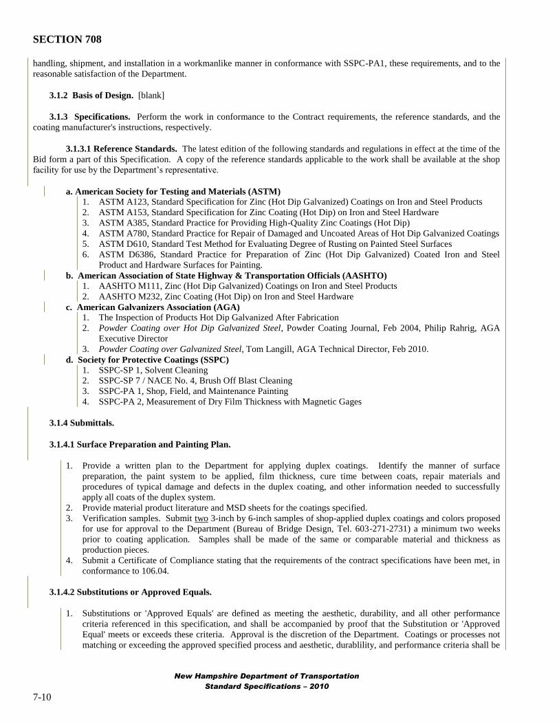
3.1.3.1 Reference Standards. The latest edition of the following standards and regulations in effect at the time of the
Bid form a part of this Specification. A copy of the reference standards applicable to the work shall be available at the shop
facility for use by the Department‟s representative.
a. American Society for Testing and Materials (ASTM)
1. ASTM A123, Standard Specification for Zinc (Hot Dip Galvanized) Coatings on Iron and Steel Products
2. ASTM A153, Standard Specification for Zinc Coating (Hot Dip) on Iron and Steel Hardware
3. ASTM A385, Standard Practice for Providing High-Quality Zinc Coatings (Hot Dip)
4. ASTM A780, Standard Practice for Repair of Damaged and Uncoated Areas of Hot Dip Galvanized Coatings
5. ASTM D610, Standard Test Method for Evaluating Degree of Rusting on Painted Steel Surfaces
6. ASTM D6386, Standard Practice for Preparation of Zinc (Hot Dip Galvanized) Coated Iron and Steel
Product and Hardware Surfaces for Painting.
b. American Association of State Highway & Transportation Officials (AASHTO)
1. AASHTO M111, Zinc (Hot Dip Galvanized) Coatings on Iron and Steel Products
2. AASHTO M232, Zinc Coating (Hot Dip) on Iron and Steel Hardware
c. American Galvanizers Association (AGA)
1. The Inspection of Products Hot Dip Galvanized After Fabrication
2. Powder Coating over Hot Dip Galvanized Steel, Powder Coating Journal, Feb 2004, Philip Rahrig, AGA
Executive Director
3. Powder Coating over Galvanized Steel, Tom Langill, AGA Technical Director, Feb 2010.
d. Society for Protective Coatings (SSPC)
1. SSPC-SP 1, Solvent Cleaning
2. SSPC-SP 7 / NACE No. 4, Brush Off Blast Cleaning
3. SSPC-PA 1, Shop, Field, and Maintenance Painting
4. SSPC-PA 2, Measurement of Dry Film Thickness with Magnetic Gages
3.1.4 Submittals.
3.1.4.1 Surface Preparation and Painting Plan.
1. Provide a written plan to the Department for applying duplex coatings. Identify the manner of surface
preparation, the paint system to be applied, film thickness, cure time between coats, repair materials and
procedures of typical damage and defects in the duplex coating, and other information needed to successfully
apply all coats of the duplex system.
2. Provide material product literature and MSD sheets for the coatings specified.
3. Verification samples. Submit two 3-inch by 6-inch samples of shop-applied duplex coatings and colors proposed
for use for approval to the Department (Bureau of Bridge Design, Tel. 603-271-2731) a minimum two weeks
prior to coating application. Samples shall be made of the same or comparable material and thickness as
production pieces.
4. Submit a Certificate of Compliance stating that the requirements of the contract specifications have been met, in
conformance to 106.04.
3.1.4.2 Substitutions or Approved Equals.
1. Substitutions or 'Approved Equals' are defined as meeting the aesthetic, durability, and all other performance
criteria referenced in this specification, and shall be accompanied by proof that the Substitution or 'Approved
Equal' meets or exceeds these criteria. Approval is the discretion of the Department. Coatings or processes not
matching or exceeding the approved specified process and aesthetic, durablility, and performance criteria shall be
New Hampshire Department of Transportation
Standard Specifications – 2010
7-10

SECTION 708
removed and replaced at the expense of the Contractor and all Subcontractors that were involved with the supply
of and application of the non-conforming product.
3.1.5 Supplier Coordination.
1. Fabricator-Galvanizer Coordination. Prior to fabrication and final submittal of shop drawings to the
Department, fabricators shall submit shop drawings to the galvanizer for all metal fabrications to receive shop-
applied duplex coatings, to review fabricator's shop drawings for suitability of materials for galvanizing and
coatings, and to coordinate any required modifications to fabrications required to be performed by the fabricator.
2. The supplier of steel products shall notify the galvanizer if the chemical composition of the steel to be galvanized
exceeds the following limits in order to determine its suitability for processing: 0.25% carbon, 0.22% silicon,
0.04% phosphorous, and 1.3% manganese.
3.2 Hot Dip Galvanizing (HDG)
3.2.1 Fabricated products shall meet the requirements of ASTM A385 (for material composition, cleanliness, drainage
vents, etc.) prior to galvanizing, and galvanized surfaces shall meet the requirements of ASTM D6386 (preparing zinc surfaces
for painting), as applicable and as stated herein.
1.
2.
3.
Galvanizing: Galvanize materials in accordance with specified standards and this specification. Galvanizingshall provide an acceptable substrate for applied coatings. The dry kettle process shall be used to eliminate anyflux inclusions on the surface of the galvanized material.Prior to galvanizing, the steel shall be immersed in a preflux solution (zinc ammonium chloride). The prefluxtank shall be 12-14 Baumé and contain less than 0.4 percent iron. The wet kettle process is prohibited.Implement the following procedures to provide the appropriate surface for the material to be galvanized:a) Utilize and regularly inspect a monitoring recorder to observe any variances in the galvanizing bath
temperature.
b) The pickling tanks shall contain hydrochloric acid with an iron content less than 8 percent and zinc content
less than 3 percent. Titrations shall be taken weekly at a minimum.
c) All chemicals and zinc content will be tested at least once a week to determine compliance with ASTM
standards. All testing will be done using atomic absorption spectrometry or x-ray fluorescence (XRF)
equipment at a lab in the galvanizing plant.
3.2.2 Surface Preparation of Hot Dip Galvanizing (HDG)
1. Prepare all surfaces in conformance to the requirements of this Item, and the approved Surface Preparation and
Painting Plan provided under 3.1.4, Submittals.
2. Prior to painting, clean and prepare galvanized surfaces as necessary to remove detrimental contaminants. (See
Powder Coating over Galvanized Steel, Feb 2010 Tom Langill for cautions regarding cleaning.) If applicable
apply cleaning materials with clean lint-free rags or soft bristle brushes frequently changed to prevent reapplying
contaminants. After cleaning, rinse thoroughly with hot water and allow the part to dry completely.
3. Prepare galvanized surfaces with SSPC-SP7, Brush-Off Blast Cleaning, using non-metallic abrasives at a reduced
nozzle pressure as recommended by the equipment manufacturer, or abraded by approved mechanical means
using sanding disks with appropriate abrasive, to thoroughly roughen the entire surface and produce a dense,
consistent, sharp, angular, uniform anchor pattern with a profile height of 1.0-1.5 mils, exhibiting a uniform gray
color free of any bright, shiny spangles and to an appearance and feel similar to sandpaper.
4. The required thickness of the zinc coating shall be maintained and checked prior to painting. Surface preparation
shall be acceptable to the paint manufacturer's requirements. Additional surface preparation or a tie coat may be
considered if required by the paint manufacturer and approved by the Department.
5. The substrate surface shall be dry and free from dust, dirt, oil, grease or other contaminants.
3.2.3. Discontinuities. All visually evident detrimental surface imperfections (e.g. flux inclusions, dross inclusions, oil)
that are present on galvanized surfaces shall be cleaned, and any high spots, rough areas and edges, spikes, and sharp
protrusions shall be removed by grinding to produce a smooth surface. Disbondment (peeling) of galvanizing is not acceptable
and the piece shall be regalvanized, or investigated for extent and severity and a repair solution proposed to the Department for
approval before corrective action is taken.
New Hampshire Department of Transportation
Standard Specifications – 2010
7-11

SECTION 708
3.2.4 Surface profiling shall be performed prior to the formation of "white rust" on the galvanized surface. If any "white
rust" is detected by visual means, the galvanizing shall be stripped off and the steel re-galvanized in conformance with these
specifications. "White rust" shall be as defined in the Inspection of Products Hot Dip Galvanized After Fabrication, Table IV,
by the American Galvanizers Association.
3.2.5 Prior to painting galvanized products shall not be nested, stacked or stored with adjacent surfaces touching but shall
be kept separated to be remain dry and permit the circulation of air between products.
3.3 Galvanized Steel Outgassing.
3.3.1 The galvanized parts shall be subjected to a thermal cycle (i.e. outgassing) after surface profiling and before paint
application. The thermal cycle should be set at the appropriate temperature and duration for the thickness of the product
recommended by the paint manufacturer.
3.4 Paint Application.
3.4.1 Time limits. The first coat of paint shall be applied within twelve (12) hours of galvanizing and within one hour of
surface preparation of the galvanized surface and outgassing, at the galvanizer‟s facility, and in a controlled environment
meeting applicable atmospheric requirements, as recommended by the coating manufacturer.
3.4.2 Paint application. Pretreatment and paint application and curing shall be performed after galvanizing in
conformance with the paint manufacturer's recommendations and shall consist of the following, unless approved otherwise:
1. Verify that the galvanized surface exhibits the specified degree of cleaning immediately prior to painting.
2. The coating and curing facility shall be maintained free of airborne dust and dirt until coatings are completely
cured.
3. Paint shall be applied according to the coating manufacturer's written specifications, maintaining even coverage
on all parts. The paint shall only be applied when both the ambient temperature is 50º F. or above, and the part
surface temperature is between 50º and 95º F., is 5º F. (min.) higher than the dew point, and the relative humidity
is less than 85 percent (max.). For the SC moisture-cure urethane use 2º F dew point differential and 98%
maximum R.H.
4. Only apply paint to surfaces that are thoroughly dry.
5. During cure, the paint coats shall be maintained in a protected environment within a min-max temperature range
of 60-95 F for the duration of the cure-to-recoat cycle listed on the paint product data sheet, unless the paint
manufacturer‟s requirements are more restrictive.
6. Apply all coats by airless or conventional spray, unless other methods are necessary. If conventional spray is
used, verify that the compressed air supply is clean and dry as determined by the blotter test in accordance with
ASTM D 4285.
7. Apply each coat of paint only after the previous coat has been allowed to dry as required by the manufacturer's
written instructions, but as soon as possible to minimize the length of time that the coating is exposed to dust and
contamination. Do not allow any coat to remain exposed for longer than 14 days prior to overcoating.
8. Apply each coat in a workmanlike manner to assure thorough wetting of the substrate or underlying coat, and to
achieve a smooth, streamline surface free of dryspray, overspray, and orange peel. Shadow-through, pinholes,
bubbles, skips, misses, lap marks between applications, or other visible discontinuities in any coat are
unacceptable. Runs or sags may be brushed out while the material remains wet.
9. Remove dryspray and overspray (e.g. by sanding) prior to the application of the next coat. When present on the
finish, remove as directed by the Department and apply another coat of finish to the area. Remove all other
defective coating to sound material and reapply
10. Thoroughly coat all surfaces with special attention to hard-to-reach areas, and irregular surfaces. When coating
configurations such as bolts, apply the material from multiple directions to assure complete coverage.
11. Apply all coats in such a manner to assure that they are well adhered to each other and to the substrate. If the
application of any coat causes lifting of an underlying coat, or there is poor adhesion between coats or to the
substrate, remove the coating in the affected area to adjacent sound, adherent coating, and reapply the material.
12. Use wet film thickness gages in conformance to ASTM D4414 to verify the thickness of each coat at the time of
application.
New Hampshire Department of Transportation
Standard Specifications – 2010
7-12
SECTION 708
13. Paint shall be applied to the minimum dry film thickness specified, and in a manner that will ensure a uniform
coating without holidays, runs, or detrimental build at edges.
14. Each coated part shall be visually inspected. Measure the coating thickness with a thickness gauge. Any part that
does meet the specified coating thickness may be recoated immediately after lightly abrading (sanding) the
surface. All parts shall be allowed to cure sufficiently before further handling.
3.4.3 Surface smoothness - Duplex coatings shall exhibit a smoothness (i.e. rugosity) not greater than 4 rug (16-20 microns
of variation) when measured by a profilometer over a 1-inch straight line on the surface of metal products less than 24 lbs/
linear foot. The profilometer shall be capable of operating in 1 micron increments.
3.4.4 Hardware shall be galvanized and fasteners exposed to view after installation shall receive the painted or powder
coated duplex coating. Furnish an application procedure to the Department. Coating procedures for fasteners are not restricted
to the same-facility (1.2) and 12-hour maximum window (3.4.1) restrictions, due to the different nature of fastener supply.
1. Bolts - Paint/powder coat bolt heads. Minor overspray is permitted on the threads.
2. Nuts - Paint/powder coat exterior nut surfaces and mask off interior surfaces.
3. Washers - Paint/powder coat all washer surfaces.
3.5 Inspection.
3.5.1 Quality Control (QC). The applicator is required to conduct and document quality control inspection of the
cleaning and painting operations including at a minimum, measurements of surface profile, surface cleanliness, dry film
coating thickness, and visual inspection for coating defects. The data shall be recorded in a log maintained at the site and
available for the Department‟s review during working hours.
3.5.2 Quality Assurance (QA). The work is subject to QA inspection by the Department.
1. Facilitate QA inspection as required, including proper notification, allowing adequate time for inspections, and
providing access to the work. Furnish, until final acceptance of the coating system, all equipment, reference
documents, and instrumentation needed to inspect all phases of the work.
2. Measure the thickness of each coat using nondestructive magnetic dry film thickness gages. Comply with SSPC
PA2 for the calibration and use of gages and the minimum frequency of thickness measurements. QA Inspectors
will not be limited by the frequency of thickness measurements of PA2 but will take measurements sufficient to
assure that proper thickness is achieved on all surfaces as specified.
3. The presence or activity of Department QA inspections in no way relieves the Contractor of the responsibility to
comply with all requirements of this Item, and to provide adequate inspections of its own to assure compliance
with the requirements of this Item.
4. Finished products will be stamped "Approved" only after the loading has been completed and approved. No
material shall be shipped without the prior approval of the Department.
3.6 Handling / Shipping / Installation.
3.6.1. Duplex-coated materials shall not be lifted, placed on supports, or loaded for shipment until the shop coating has
been adequately cured and inspected.
3.6.2. Protective measures. Exercise care in handling shop-coated materials in the shop, and during storage, shipping,
field installation, and subsequent construction to protect the coating from any scraping, marring, or other damage to the surface
finish. Coated material shall be insulated from lifting devices and from the scraping and rubbing of parts that would damage
the coating, by the use of lifting softeners, nylon slings, padded cables, storage pallets, separators, cushioners, tie-downs, and
other approved supports. Individual parts shall be wrapped or padded with effective protective material (e.g. foam, not paper
or cardboard).
3.6.3. Installation. Comply with fabricator's and galvanizer's requirements for installation of materials and fabrications,
including use of nylon slings or padded cables for handling shop-coated materials.
New Hampshire Department of Transportation
Standard Specifications – 2010
7-13

SECTION 708
3.7 Touch-Up and Repairs.
3.7.1 The total repair area shall be less than one quarter of one percent ( 0.25% ) of the area of an individual member, or
the member shall be rejected and regalvanized and recoated with the duplex coating. [The repair area definition is comparable
to Rust Grade 7 in ASTM D610, Standard Test Method for Evaluating Degree of Rusting on Painted Steel Surfaces.]
3.7.2 HDG- Repair damaged galvanizing and bare steel surfaces in accordance with ASTM A780, Standard Practice for
Repair of Damaged Hot Dipped Galvanized Coatings, Annex A2. Thoroughly clean damaged areas to produce a clean, bare
and dry bright metal surface with a roughened profile and feather into the edges of adjacent undamaged galvanizing. Use a
power sanding disk per SSPC-SP3. For bolts use a thorough hand wire brushing and SP1 cleaning as a minimum.
3.7.3 Apply an approved organic zinc-rich repair paint containing 92 percent (min.) zinc by weight in the dry film,
according to the manufacturer‟s recommendations, in two to four coats to a thickness equivalent to the surrounding
galvanizing. Silver paint, brite paint, or aluminum paint is not acceptable.
3.7.4 Paint - The repair to the paint may be a liquid and brushed on or an aerosol and sprayed, whichever is appropriate to
achieve an aesthetic finish and as long as the coats, cure, and minimum thickness of the original system are achieved. The
Contractor shall provide a dry film thickness gage and check the thickness of the repair areas. Touch-ups shall be such that the
repair is not noticeably visible from a distance of six feet.
1. The field-touch-up of shop-applied finish coatings shall be performed or supervised by personnel from the duplex
coating facility for the warranty to apply.
2. Touch up fasteners in the field after installation, assuming there may be mechanical damage to nuts during
tensioning fasteners.
3. Touch-up repair kits in sufficient quantity and touchup instructions shall be provided to the field for each type of
shop-applied finish. Additional touchup repair kits and instructions shall be furnished to the Department for use
after project acceptance for maintenance repairs.
3.8 Final Acceptance.
Although the Department‟s QA Inspector may accept the finished duplex coated fabricated products before shipment to the
jobsite, final acceptance of the duplex coat system by the Department will occur at the jobsite after installation of the product,
and after all coats and repairs have been completed.
3.9 Three-Year Warranty.
Should the duplex system fail within three years after the project has been accepted, the coating shall be repaired or
replaced by the Contractor at no cost to the State. The extent and method of repair must be acceptable to the Department.
System failure does not include damage from external agents, such as scraping from snow removal equipment, vandalism,
debris impacts, collisions, etc., or normal loss of gloss and color. Once the duplex system has been accepted, a failure shall
mean any visible corrosion, blistering, checking, cracking, or delamination (peeling) of the galvanizing or paint resulting from
the installation of the product or from the performance of the duplex coating.
New Hampshire Department of Transportation
Standard Specifications – 2010
7-14

SECTION 708
APPENDIX B
DUPLEX COATINGS - POWDER COATING OVER GALVANIZING
Highlight these requirements:
Apply galvanizing and powder coating within the same facility (see 1.2);
Apply first powder coating over galvanizing within a maximum 12-hour window (see 3.4.1).
DESCRIPTION
1.1 General. This appendix specifies a duplex coating, consisting of hot dip galvanizing and high-performance, shop-
applied, thermosetting-based, super-durable powder coatings, for fabricated steel products for exterior use, as shown on the
plans or as directed.
1.2 Duplex Coating Facility. The galvanizer shall be qualified and have demonstrated a minimum of ten years experience
in the successful application of hot dip galvanizing using the dry kettle process, and a minimum of five years experience in the
successful application of powder coatings over galvanizing within the same facility.
1.3 Scope Of Work. All fabricated products and components, as shown on the plans or as directed, shall be furnished with
a duplex coating color finish as described. See Summary Table 1.3.
MATERIALS
2.1 Galvanizing. Hot dip galvanizing shall conform to AASHTO M111 (ASTM A123) and utilize the dry kettle process in a
bath of molten zinc. The galvanizing kettle shall contain special high grade zinc, nickel, and other earthly materials. The
galvanizing process shall not include quenching with water or treatment with a chromate conversion coating. Provide
thickness of galvanizing specified in the reference standards. Hardware shall be hot dip galvanized in conformance with
AASHTO M232 (ASTM A153).
2.2 Abrasives. Provide abrasives that are dry and free of oil, grease, and corrosion-producing, or other deleterious
contaminants. Provide an abrasive that is sized to produce a dense, consistent, sharp, angular, uniform anchor pattern with a
profile height of 1.0-1.5 mils, unless the requirements of the coating manufacturer are more restrictive. The use of iron shot,
steel shot, aluminum oxide grit, sand, or coal slag products as blast abrasives, and power wire brushes are NOT permitted. Use
approved abrasives [e.g. garnet, stainless steel grit, Dupont StarBlast® XL (fractured), etc.] that will not leave a residue on the
galvanized surface after blowing down with compressed air.
2.3 Powder Coating. The duplex coating shall be a two-coat shop-applied, oven-cured, high performance, exterior
thermosetting powder coating consisting of a durable zinc-rich powder coating primer, and a super-durable powder coating
topcoat applied over hot dipped galvanized (HDG) steel substrates. For extra protection a third coat consisting of a powder
clearcoat may be specified.
SCOPE OF WORK - SUMMARY TABLE 1.3
Treatment Surfaces to be powder coated,
as shown on the plans * Duplex System (2.3) Final Color (satin)
Standard example: Hot Dip Galvanizing,
Dark Brown u.n.o.
(use u.n.o.) Item 606.000, Steel Beam for Beam
Guardrail
plus durable powder primer, and
super durable powder topcoat Fed # 20062
Extra
Protection
example:
Item 563.5208, Bridge Pedestrian Rail
(Galv-Powder Coated)
Hot Dip Galvanizing,
plus durable powder primer,
super durable powder topcoat,
and powder clearcoat
Dark Brown u.n.o.
Fed # 20062
* Fasteners exposed to view after installation shall receive duplex coating per section 3.4.4 and 3.7.4.(2).
2.3.1 Furnish powder coating materials from one of the following approved suppliers:
New Hampshire Department of Transportation
Standard Specifications – 2010
7-15
SECTION 708
1. AkzoNobel
2. PPG
3. Sherwin Williams
4. TIGER Drylac
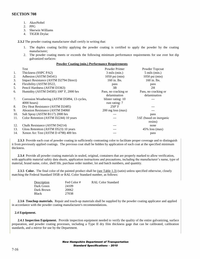
2.3.2 The powder coating manufacturer shall certify in writing that:
1. The duplex coating facility applying the powder coating is certified to apply the powder by the coating
manufacturer;
2. The powder coating meets or exceeds the following minimum performance requirements for use over hot dip
galvanized surfaces:
Powder Coating (min.) Performance Requirements
Test Powder Primer Powder Topcoat
1. Thickness (SSPC PA2) 3 mils (min.) 5 mils (min.)
2. Adhesion (ASTM D4541) 1050 psi (min) 1050 psi (min)
3. Impact Resistance (ASTM D2794 Direct) 160 in. lbs. 160 in. lbs.
4. Flexibility (ASTM D522, pass pass
5. Pencil Hardness (ASTM D3363) 3B 2H
6. Humidity (ASTM D4585) 100º F, 2000 hrs Pass, no cracking or Pass, no cracking ordelamination delamination
7. Corrosion Weathering (ASTM D5894, 13 cycles, blister rating: 10 --4000 hours) rust rating: 7
8. Dry Heat Resistance (ASTM D2485) 250º F --
9. Abrasion Resistance (ASTM D4060 200 mg loss (max) --
10. Salt Spray (ASTM B117) 2000 hrs --- pass
11. Color Retention (ASTM D2244) 10 years --- 3∆E (based on inorganic resins)
12. Chalk Resistance (ASTM D4214) --- none
13. Gloss Retention (ASTM D523) 10 years --- 45% loss (max)
14. Xenon Arc Test (ASTM D 4798) 400 hrs --- pass
2.3.3 Provide each coat of powder coating in sufficiently contrasting color to facilitate proper coverage and to distinguish
it from previously applied coatings. The previous coat shall be hidden by application of each coat at the specified minimum
thickness.
2.3.4 Provide all powder coating materials in sealed, original, containers that are properly marked to allow verification,
with applicable material safety data sheets, application instructions and precautions, including the manufacturer‟s name, type of
material, brand name, color, shelf life, purchase order number, lot and batch numbers, and quantity.
2.3.5 Color. The final color of the painted product shall be (see Table 1.3) (satin) unless specified otherwise, closely
matching the Federal Standard 595B or RAL Color Standard number, as follows:
Description Fed Color # RAL Color StandardDark Green 24109Dark Brown 20062Black 27038
2.3.6 Touchup materials. Repair and touch-up materials shall be supplied by the powder coating applicator and applied
in accordance with the powder coating manufacturer's recommendations.
2.4 Equipment.
2.4.1 Inspection Equipment. Provide inspection equipment needed to verify the quality of the entire galvanizing, surface
preparation, and powder coating processes, including a Type II dry film thickness gage that can be calibrated, calibration
standards, and a mirror for use by the Department.
New Hampshire Department of Transportation
Standard Specifications – 2010
7-16

SECTION 708
Duplex Coatings - Powder Coating Over Galvanizing
3.1 General
3.1.1 Provide all materials, equipment, and labor necessary to perform the scope of work whether or not the material or
equipment is specifically identified in this Item. Conduct all galvanizing, surface preparation, powder coating operations,
handling, shipment, and installation in a workmanlike manner in conformance with SSPC-PA1, these requirements, and to the
reasonable satisfaction of the Department.
3.1.2 Basis of Design. [blank]
3.1.3 Specifications. Perform the work in conformance to the Contract requirements, the reference standards, and the
coating manufacturer's instructions, respectively.
3.1.3.1 Reference Standards. The latest edition of the following standards and regulations in effect at the time of the
Bid form a part of this Specification. A copy of the reference standards applicable to the work shall be available at the shop
facility for use by the Department‟s representative.
a. American Society for Testing and Materials (ASTM)
7. ASTM A123, Standard Specification for Zinc (Hot Dip Galvanized) Coatings on Iron and Steel Products
8. ASTM A153, Standard Specification for Zinc Coating (Hot Dip) on Iron and Steel Hardware
9. ASTM A385, Standard Practice for Providing High-Quality Zinc Coatings (Hot Dip)
10. ASTM A780, Standard Practice for Repair of Damaged and Uncoated Areas of Hot Dip Galvanized Coatings
11. ASTM D610, Standard Test Method for Evaluating Degree of Rusting on Painted Steel Surfaces
12. ASTM D6386, Standard Practice for Preparation of Zinc (Hot Dip Galvanized) Coated Iron and Steel
Product and Hardware Surfaces for Painting.
b. American Association of State Highway & Transportation Officials (AASHTO)
3. AASHTO M111, Zinc (Hot Dip Galvanized) Coatings on Iron and Steel Products
4. AASHTO M232, Zinc Coating (Hot Dip) on Iron and Steel Hardware
c. American Galvanizers Association (AGA)
4. The Inspection of Products Hot Dip Galvanized After Fabrication
5. Powder Coating over Hot Dip Galvanized Steel, Powder Coating Journal, Feb 2004, Philip Rahrig, AGA
Executive Director
6. Powder Coating over Galvanized Steel, Tom Langill, AGA Technical Director, Feb 2010.
d. Society for Protective Coatings (SSPC)
5. SSPC-SP 1, Solvent Cleaning
6. SSPC-SP 7 / NACE No. 4, Brush Off Blast Cleaning
7. SSPC-PA 1, Shop, Field, and Maintenance Painting
8. SSPC-PA 2, Measurement of Dry Film Thickness with Magnetic Gages
3.1.4 Submittals.
3.1.4.1 Surface Preparation and Powder Coating Plan.
5. Provide a written plan to the Department for applying duplex coatings. Identify the manner of surface
preparation, the powder coat system to be applied, film thickness, cure time between coats, repair materials and
procedures of typical damage and defects in the duplex coating, and other information needed to successfully
apply all coats of the duplex system.
6. Provide material product literature and MSD sheets for the coatings specified, along with test data indicating
conformance to the performance criteria required.
7. Verification samples. Submit six 3-inch by 6-inch samples of shop-applied duplex coatings and colors proposed
for use for approval to the Department (Bureau of Bridge Design, Tel. 603-271-2731) a minimum four weeks
prior to coating application. Samples shall be made of the same or comparable material and thickness as
production pieces.
New Hampshire Department of Transportation
Standard Specifications – 2010
7-17

SECTION 708
8. Submit a Certificate of Compliance stating that the requirements of the contract specifications have been met, in
conformance to 106.04.
3.1.4.2 Substitutions or Approved Equals.
2. Substitutions or 'Approved Equals' are defined as meeting the aesthetic, durability, and all other performance
criteria described in this specification, and shall be accompanied by proof that the Substitution or 'Approved
Equal' meets or exceeds these criteria. Approval is the discretion of the Department. Coatings or processes not
matching or exceeding the approved specified process and aesthetic, durablility, and performance criteria shall be
removed and replaced at the expense of the Contractor and all Subcontractors that were involved with the supply
of and application of the non-conforming product.
3.1.5 Supplier Coordination.
9. Fabricator-Galvanizer Coordination. Prior to fabrication and final submittal of shop drawings to the
Department, fabricators shall submit shop drawings to the galvanizer for all metal fabrications to receive shop-
applied duplex coatings, to review fabricator's shop drawings for suitability of materials for galvanizing and
coatings, and to coordinate any required modifications to fabrications required to be performed by the fabricator.
3. The supplier of steel products shall notify the galvanizer if the chemical composition of the steel to be galvanized
exceeds the following limits in order to determine its suitability for processing: 0.25% carbon, 0.22% silicon,
0.04% phosphorous, and 1.3% manganese.
3.2 Hot Dip Galvanizing (HDG)
3.2.1 Fabricated products shall meet the requirements of ASTM A385 (for material composition, cleanliness, drainage
vents, etc.) prior to galvanizing, and galvanized surfaces shall meet the requirements of ASTM D6386 (preparing zinc surfaces
for painting), as applicable and as stated herein.
4.
5.
6.
Galvanizing: Galvanize materials in accordance with specified standards and this specification. Galvanizing
shall provide an acceptable substrate for applied coatings. The dry kettle process shall be used to eliminate any
flux inclusions on the surface of the galvanized material.
Prior to galvanizing, the steel shall be immersed in a preflux solution (zinc ammonium chloride). The preflux
tank shall be 12-14 Baumé and contain less than 0.4 percent iron. The wet kettle process is prohibited.
Implement the following procedures to provide the appropriate surface for the material to be galvanized:
a) Utilize and regularly inspect a monitoring recorder to observe any variances in the galvanizing bath
temperature.
b) The pickling tanks shall contain hydrochloric acid with an iron content less than 8 percent and zinc content
less than 3 percent. Titrations shall be taken weekly at a minimum.
c) All chemicals and zinc content will be tested at least once a week to determine compliance with ASTM
standards. All testing will be done using atomic absorption spectrometry or x-ray fluorescence (XRF)
equipment at a lab in the galvanizing plant.
3.2.2 Surface Preparation of Hot Dip Galvanizing (HDG)
6. Prepare all surfaces in conformance to the requirements of this Item, and the approved Surface
Preparation/Powder coating Plan provided under 3.1.4, Submittals.
7. Prior to powder coating, clean and prepare galvanized surfaces as necessary to remove detrimental contaminants.
(See Powder Coating over Galvanized Steel, Feb 2010 Tom Langill for cautions regarding cleaning.) If
applicable apply cleaning materials with clean lint-free rags or soft bristle brushes frequently changed to prevent
reapplying contaminants. After cleaning, rinse thoroughly with hot water and allow the part to dry completely.
8. Prepare galvanized surfaces with SSPC-SP7, Brush-Off Blast Cleaning, using non-metallic abrasives at a reduced
nozzle pressure as recommended by the equipment manufacturer, or abraded by approved mechanical means
using sanding disks with appropriate abrasive, to thoroughly roughen the entire surface and produce a dense,
consistent, sharp, angular, uniform anchor pattern with a profile height of 1.0-1.5 mils, exhibiting a uniform gray
color free of any bright, shiny spangles and to an appearance and feel similar to sandpaper.
New Hampshire Department of Transportation
Standard Specifications – 2010
7-18
SECTION 708
9. The required thickness of the zinc coating shall be maintained and checked prior to powder coating. Surface
preparation shall be acceptable to the powder coating manufacturer's requirements. Additional surface
preparation or a tie coat may be considered if required by the powder coating manufacturer and approved by the
Department.
10. The substrate surface shall be dry and free from dust, dirt, oil, grease or other contaminants.
3.2.3. Discontinuities. All visually evident detrimental surface imperfections (e.g. flux inclusions, dross inclusions, oil)
that are present on galvanized surfaces shall be cleaned, and any high spots, rough areas and edges, spikes, and sharp
protrusions shall be removed by grinding to produce a smooth surface. Disbondment (peeling) of galvanizing is not acceptable
and the piece shall be regalvanized, or investigated for extent and severity and a repair solution proposed to the Department for
approval before corrective action is taken.
3.2.4 Surface profiling shall be performed prior to the formation of "white rust" on the galvanized surface. If any "white
rust" is detected by visual means, the galvanizing shall be stripped off and the steel re-galvanized in conformance with these
specifications. "White rust" shall be as defined in the Inspection of Products Hot Dip Galvanized After Fabrication, Table IV,
by the American Galvanizers Association.
3.2.5 Prior to powder coating galvanized products shall not be nested, stacked or stored with adjacent surfaces touching
but shall be kept separated to be remain dry and permit the circulation of air between products.
3.3 Galvanized Steel Outgassing.
3.3.1 The galvanized parts shall be subjected to a thermal cycle (i.e. outgassing) after surface profiling and before powder
coating application. The thermal cycle should be set at the appropriate temperature and duration for the thickness of the
product recommended by the powder coating manufacturer.
3.4 Powder Coat Application.
3.4.1 Time limits. The first coat of powder coating shall be applied within twelve (12) hours of galvanizing and within
one hour of surface preparation of the galvanized surface and outgassing, at the galvanizer‟s facility, and in a controlled
environment meeting applicable atmospheric requirements, as recommended by the coating manufacturer.
3.4.2 Powder coating application. Pretreatment and powder coating application and curing shall be performed after
galvanizing in conformance with the powder coating manufacturer's recommendations and shall consist of the following,
unless approved otherwise:
15. Verify that the galvanized surface exhibits the specified degree of cleaning immediately prior to powder coating.
16. The coating and curing facility shall be maintained free of airborne dust and dirt until coatings are completely
cured.
17. The powder coating shall be electostatically applied according to the coating manufacturer's written
specifications, maintaining even coverage on all parts. The powder shall only be applied when both the ambient
temperature is 65º F. or above, and the part surface temperature is between 60º and 95º F., and is (min.) 5º F.
higher than the dew point. Relative humidity shall be less than 85 percent (max.).
18. After applying the powder, all parts shall be placed in an oven, cured and bonded at the manufacturer's
recommended levels (e.g. approximately 392º F. for 25 minutes). The Contractor shall ensure that a stable
transfer exists between the powder application system and the curing oven to prevent the loss of powder from the
parts.
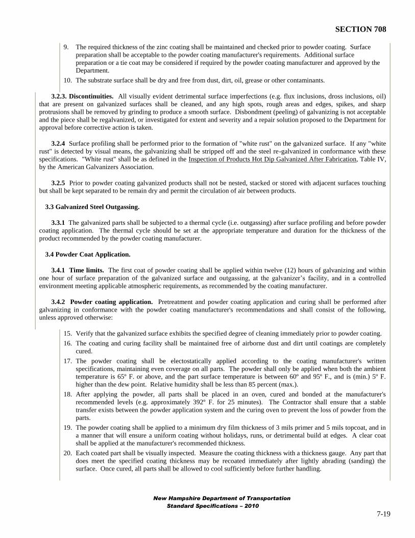
19. The powder coating shall be applied to a minimum dry film thickness of 3 mils primer and 5 mils topcoat, and in
a manner that will ensure a uniform coating without holidays, runs, or detrimental build at edges. A clear coat
shall be applied at the manufacturer's recommended thickness.
20. Each coated part shall be visually inspected. Measure the coating thickness with a thickness gauge. Any part that
does meet the specified coating thickness may be recoated immediately after lightly abrading (sanding) the
surface. Once cured, all parts shall be allowed to cool sufficiently before further handling.
New Hampshire Department of Transportation
Standard Specifications – 2010
7-19
SECTION 708
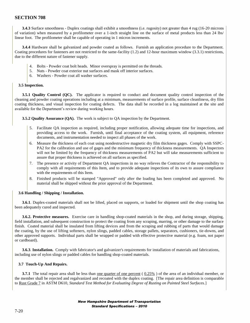
3.4.3 Surface smoothness - Duplex coatings shall exhibit a smoothness (i.e. rugosity) not greater than 4 rug (16-20 microns
of variation) when measured by a profilometer over a 1-inch straight line on the surface of metal products less than 24 lbs/
linear foot. The profilometer shall be capable of operating in 1 micron increments.
3.4.4 Hardware shall be galvanized and powder coated as follows. Furnish an application procedure to the Department.
Coating procedures for fasteners are not restricted to the same-facility (1.2) and 12-hour maximum window (3.3.1) restrictions,
due to the different nature of fastener supply.
4. Bolts - Powder coat bolt heads. Minor overspray is permitted on the threads.
5. Nuts - Powder coat exterior nut surfaces and mask off interior surfaces.
6. Washers - Powder coat all washer surfaces.
3.5 Inspection.
3.5.1 Quality Control (QC). The applicator is required to conduct and document quality control inspection of the
cleaning and powder coating operations including at a minimum, measurements of surface profile, surface cleanliness, dry film
coating thickness, and visual inspection for coating defects. The data shall be recorded in a log maintained at the site and
available for the Department‟s review during working hours.
3.5.2 Quality Assurance (QA). The work is subject to QA inspection by the Department.
5. Facilitate QA inspection as required, including proper notification, allowing adequate time for inspections, and
providing access to the work. Furnish, until final acceptance of the coating system, all equipment, reference
documents, and instrumentation needed to inspect all phases of the work.
6. Measure the thickness of each coat using nondestructive magnetic dry film thickness gages. Comply with SSPC
PA2 for the calibration and use of gages and the minimum frequency of thickness measurements. QA Inspectors
will not be limited by the frequency of thickness measurements of PA2 but will take measurements sufficient to
assure that proper thickness is achieved on all surfaces as specified.
7. The presence or activity of Department QA inspections in no way relieves the Contractor of the responsibility to
comply with all requirements of this Item, and to provide adequate inspections of its own to assure compliance
with the requirements of this Item.
8. Finished products will be stamped "Approved" only after the loading has been completed and approved. No
material shall be shipped without the prior approval of the Department.
3.6 Handling / Shipping / Installation.
3.6.1. Duplex-coated materials shall not be lifted, placed on supports, or loaded for shipment until the shop coating has
been adequately cured and inspected.
3.6.2. Protective measures. Exercise care in handling shop-coated materials in the shop, and during storage, shipping,
field installation, and subsequent construction to protect the coating from any scraping, marring, or other damage to the surface
finish. Coated material shall be insulated from lifting devices and from the scraping and rubbing of parts that would damage
the coating, by the use of lifting softeners, nylon slings, padded cables, storage pallets, separators, cushioners, tie-downs, and
other approved supports. Individual parts shall be wrapped or padded with effective protective material (e.g. foam, not paper
or cardboard).
3.6.3. Installation. Comply with fabricator's and galvanizer's requirements for installation of materials and fabrications,
including use of nylon slings or padded cables for handling shop-coated materials.
3.7 Touch-Up And Repairs.
3.7.1 The total repair area shall be less than one quarter of one percent ( 0.25% ) of the area of an individual member, or
the member shall be rejected and regalvanized and recoated with the duplex coating. [The repair area definition is comparable
to Rust Grade 7 in ASTM D610, Standard Test Method for Evaluating Degree of Rusting on Painted Steel Surfaces.]
New Hampshire Department of Transportation
Standard Specifications – 2010
7-20
SECTION 708
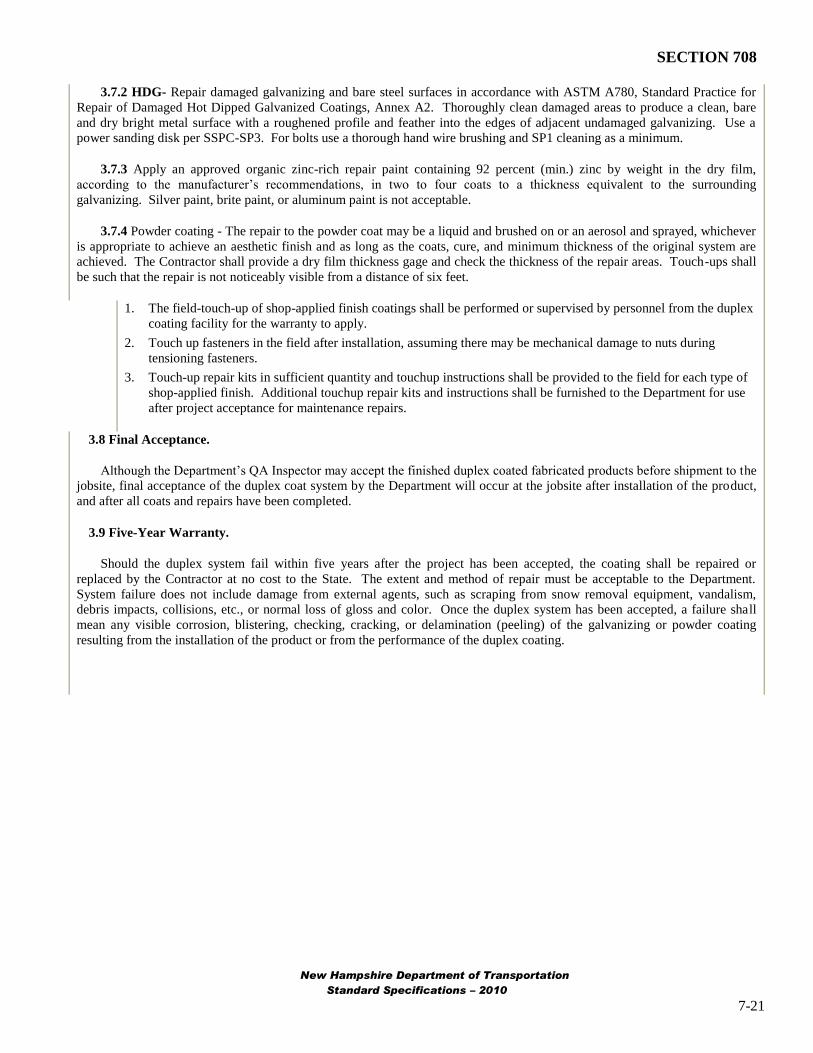
3.7.2 HDG- Repair damaged galvanizing and bare steel surfaces in accordance with ASTM A780, Standard Practice for
Repair of Damaged Hot Dipped Galvanized Coatings, Annex A2. Thoroughly clean damaged areas to produce a clean, bare
and dry bright metal surface with a roughened profile and feather into the edges of adjacent undamaged galvanizing. Use a
power sanding disk per SSPC-SP3. For bolts use a thorough hand wire brushing and SP1 cleaning as a minimum.
3.7.3 Apply an approved organic zinc-rich repair paint containing 92 percent (min.) zinc by weight in the dry film,
according to the manufacturer‟s recommendations, in two to four coats to a thickness equivalent to the surrounding
galvanizing. Silver paint, brite paint, or aluminum paint is not acceptable.
3.7.4 Powder coating - The repair to the powder coat may be a liquid and brushed on or an aerosol and sprayed, whichever
is appropriate to achieve an aesthetic finish and as long as the coats, cure, and minimum thickness of the original system are
achieved. The Contractor shall provide a dry film thickness gage and check the thickness of the repair areas. Touch-ups shall
be such that the repair is not noticeably visible from a distance of six feet.
1. The field-touch-up of shop-applied finish coatings shall be performed or supervised by personnel from the duplex
coating facility for the warranty to apply.
2. Touch up fasteners in the field after installation, assuming there may be mechanical damage to nuts during
tensioning fasteners.
3. Touch-up repair kits in sufficient quantity and touchup instructions shall be provided to the field for each type of
shop-applied finish. Additional touchup repair kits and instructions shall be furnished to the Department for use
after project acceptance for maintenance repairs.
3.8 Final Acceptance.
Although the Department‟s QA Inspector may accept the finished duplex coated fabricated products before shipment to the
jobsite, final acceptance of the duplex coat system by the Department will occur at the jobsite after installation of the product,
and after all coats and repairs have been completed.
3.9 Five-Year Warranty.
Should the duplex system fail within five years after the project has been accepted, the coating shall be repaired or
replaced by the Contractor at no cost to the State. The extent and method of repair must be acceptable to the Department.
System failure does not include damage from external agents, such as scraping from snow removal equipment, vandalism,
debris impacts, collisions, etc., or normal loss of gloss and color. Once the duplex system has been accepted, a failure shall
mean any visible corrosion, blistering, checking, cracking, or delamination (peeling) of the galvanizing or powder coating
resulting from the installation of the product or from the performance of the duplex coating.
New Hampshire Department of Transportation
Standard Specifications – 2010
7-21

SECTION 716
SECTION 716 -- WELDING OF
ALUMINUM ALLOYS FOR HIGHWAY STRUCTURES
1. General.
1.1 Description. These specifications apply to the welding of aluminum alloys used in bridge railing, structural supports
for highway signs, luminaires, traffic signals, and the like.
1.2 Specifications.
1.2.1 The welding terms used in these specifications shall be interpreted in accordance with the definitions given in the
latest edition of Welding Terms and Definitions, ANSI/AWS A3.0.
1.2.2 The welding symbols used on the plans will be those shown in the latest edition of Symbols for Welding, Brazing
and Nondestructive Examination, ANSI/AWS A2.4. Special conditions will be fully explained by added notes or details.
1.2.3 The welding of aluminum bridge railing shall conform to Section 10 of the ANSI/AWS D1.2 “Structural Welding
Code – Aluminum” including Part E “Workmanship Class II Structures”. The fabrication and erection of bridge railing shall
conform to Section 6 of the Specifications for Aluminum Structures, published by the Aluminum Association.
1.2.4 The welding of aluminum sign supports, luminaires, and traffic signals shall conform to Section 10 of the
ANSI/AWS D1.2 “Structural Welding Code – Aluminum” including Part D “Workmanship Class I Structures”.. The
fabrication and erection of aluminum sign supports, luminaires, and traffic signals shall conform to the requirements of the
AASHTO Standard Specifications for Structural Supports for Highway Signs, Luminaires and Traffic Signals. Special
consideration may be given to certain support structures, which may be fabricated according to the provisions of 1.2.3.
2. Base Metals.
2.1 The aluminum alloys to be welded under these specifications may be any of the following alloy designations:
Wrought non-heat-treatable alloysAlloy 3003Alloy 3004Alloy 5052Alloy 5083Alloy 5086Alloy 5456
Wrought heat-treatable alloysAlloy 6061Alloy 6063
Cast heat-treatable alloyAlloy 356.0
2.2 Material used for permanent backing shall be at least equivalent in weldability to the base metal being welded.
3. Welding Processes.
3.1 These specifications include provisions for welding by the gas metal-arc process and the gas tungsten-arc process.
Other processes may not be used except as permitted.
New Hampshire Department of Transportation
Standard Specifications – 2010
7-22

SECTION 716
4. Filler Metal.
4.1 Bare wire electrodes for use with the gas metal-arc process and welding rods for use with the gas tungsten-arc process
shall conform to the requirements of the latest edition of Specification for Bare Aluminum and Aluminum Alloy, Welding
Electrodes and Rods, ANSI/AWS A5.10.
4.2 Tungsten electrodes for the gas tungsten-arc process shall conform to the requirements of the latest edition of
Specification for Tungsten and Tungsten Alloy Electrodes for Arc Welding, ANSI/AWS A5.12.
4.3 Filler metals to be used with particular base metals shall be as shown in Table 1. Other filler metals may be used as
approved.
Table 1 - Filler Metal Guide for Gas Shielded Arc Welding
Base Metals Filler Metal
3003 to 3003 ER1100
3004 to 3004 ER4043
5052 to 5052 ER5654*
5083 to 5083 ER5183*
5086 to 5086 ER5356*
5456 to 5456 ER5556*
6061 to 6061 ER4043*
6063 to 6063 ER5356*
356.0 to 6061 ER4043
356.0 to 6063 ER4043
* ER5183, ER5356, and ER5556 may be used interchangeably for these base metals.
4.4 Filler metals shall be kept covered and stored in a dry place at relatively uniform temperatures. Original rod or wire
containers shall not be opened until ready for use. Rod and wire shall be free of moisture, lubricant, or other contaminants.
Spools of wire temporarily left unused on the welding machine shall be kept covered to avoid contamination by dirt and grease
collecting on the wire. If a spool of wire is to be unused for more than a short length of time, the spool shall be returned to the
carton, and the carton shall be tightly resealed.
5. Shielding Gases.
5.1 Shielding gases shall be welding grade or better.
5.2 Shielding gas for gas metal-arc welding shall be argon, helium, or a mixture of the two (at least 50 percent helium).
5.3 Shielding gas for gas tungsten-arc welding done with alternating current shall be argon.
5.4 Shielding gas for gas tungsten-arc welding done with direct current, straight-polarity, shall be helium.
5.5 Hoses used for shielding gases shall be made of synthetic rubber or plastic. Natural rubber hoses shall not be used.
Hoses that have been previously used for acetylene or other gases shall not be used.
6. Preparation of Materials.
6.1 Joint details shall be in accordance with design requirements and detail drawings. The locations of joints shall not be
changed without approval.
6.2 Edge preparation shall be by sawing, machining, clipping, or shearing. Gas tungsten-arc or gas metal arc cutting may
also be used. Cut surfaces shall meet the ANSI surface roughness rating value of 1000. Oxygen cutting shall not be used.
6.3 Surfaces and edges to be welded shall be free from fins, tears, and other defects which would adversely affect the
quality of the weld.
New Hampshire Department of Transportation
Standard Specifications – 2010
7-23

SECTION 716
6.4 Dirt, grease, forming or machining lubricants, or any organic materials shall be removed from the areas to be welded
by cleaning with a suitable solvent or by vapor degreasing.
6.5 On all edges and surfaces to be welded, the oxide shall be removed just prior to welding by wire brushing or by other
mechanical methods, such as rubbing with steel wool or abrasive cloth, scraping, filing, rotary planing, or sanding. If wire
brushing is used, the brushes shall be made of stainless steel. Hand or power driven wire brushes which have been used on
other materials shall not be used on aluminum.
6.6 Where mechanical methods of oxide removal are found to be inadequate, a standard chemical method shall be used.
Welding shall be done within 24 hours after chemical treatment.
6.7 When gas tungsten-arc welding with direct current, straight polarity, is being used, all edges and surfaces to be welded
shall have the oxide removed by a standard chemical method.
6.8 Welding shall not be done on anodically treated aluminum unless the condition is removed from the joint area to be
welded.
7. Welding Procedure.
7.1 All butt welds requiring 100 percent penetration, except those produced with the aid of backing, shall have the root of
the initial weld chipped or machined out to sound metal before welding is started from the second side. Butt welds made with
the use of backing shall have the weld metal thoroughly fused with the backing. Where accessible, backing for welds that are
subject to computed stress or that are exposed to view on the completed structure, and that are not otherwise parts of the
structure, shall be removed and the joints ground or machined smooth. In tubular members, butt welds subjected to computed
stresses shall be made with the aid of permanent backing rings or strips.
7.2 The procedure used for production welding of any particular joint shall be the same as used in the procedure
qualification for that joint.
7.3 All welding operations, either shop or field, shall be protected from air currents or drafts so as to prevent any loss of
gas shielding during welding. Adequate gas shielding shall be provided to protect the molten metal during solidification.
7.4 The work shall be positioned for flat position welding whenever practicable.
7.5 In both shop and field, all weld joints shall be dry at the time of welding.
7.6 The size of the electrode, voltage, amperage, welding speed, gas or gas mixture, and gas flow rate shall be suitable for
the thickness of the material, design of joint, welding position, and other circumstances attending the work.
7.7 Gas metal-arc welding shall be done with direct current, reverse polarity.
7.8 Gas tungsten-arc welding shall be done with alternating current or with direct current, straight polarity.
7.9 When the joint to be welded requires specific root penetration, the Contractor shall make a sample joint and a
macroetched cross-section of the weld to demonstrate that the joint welding procedure to be used attains the required root
penetration. The sample joint shall have a length of at least 1 ft (300 mm) ) and shall be welded with the electrode, polarity,
amperage, voltage, speed, gas mixture, and gas flow rate that are proposed to be used in production welding. The Engineer, at
his discretion, may accept evidence on record in lieu of the preceding test.
7.10 Where preheat is needed, the temperature of preheat shall not exceed 350 ºF (175 C) for heat-treated alloys and 600
ºF (315 C) for non-heat-treated alloys. The temperature shall be measured by temperature-indicating crayons or by
pyrometric equipment. Heat-treated alloys shall not be held at the maximum preheat temperature or at temperatures near the
maximum for more than 30 minutes.
New Hampshire Department of Transportation
Standard Specifications – 2010
7-24

SECTION 716
8. Weld Quality.
8.1 Regardless of the method of inspection, the acceptance or rejection of welds shall be determined by the following
conditions:
(a) Cracks in welds or adjacent base metal will not be acceptable.
(b) Copper inclusions will not be acceptable.
(c) Porosity in excess of that permitted by Section 3 and Section 10 of the ANSI/AWS D1.2 “Structural Welding
Code – Aluminum” will not be acceptable.
(d) Lack of fusion, incomplete penetration, or tungsten or oxide inclusion will be acceptable only if small and well
dispersed.
8.2 Undercut shall not be more than 0.01 in. (0.25 mm) deep when its direction is transverse to the primary stress in the
part that is undercut. Undercut shall not be more than 1/32 in. (0.80 mm) deep when its direction is parallel to the primary
stress in the part that is undercut.
8.3 No overlap shall be allowed.
8.4 All craters shall be filled to the full cross-section of the welds.
8.5 Welds having defects greater than the levels of acceptance specified above shall be considered as rejected unless
corrected in accordance with 716.10.
9. Inspection.
9.1 To determine compliance with Section 7, all welds shall be visually inspected, and in addition, all welds subject to
computed stress shall be inspected by the dye penetrant method except as specified in 9.4.
9.2 For truss-type highway sign structures, the dye penetrant method shall be used on butt welds in columns and main
chord members, on fillet welds connecting columns to bases and main chord members, including the associated flanges,
gussets, or main load carrying brackets or members, and also on fillet welds connecting flanges to the main truss chord
members. On pole type and common light standards, the dye penetrant method shall be used on butt welds in columns and on
fillet welds connecting columns to bases.
9.3 The dye penetrant tests shall be performed in accordance with the requirements of ASTM E 165, Method B,
Procedures B-2 or B-3.
9.4 Dye penetrant inspection may be omitted provided that the Inspector examines each layer of weld metal with a
magnifier of 3X minimum before the next successive layer is deposited.
10. Corrections.
10.1 In lieu of rejection of an entire piece or member containing welding that is unacceptable, the corrective measures
listed below may be permitted by the Engineer, whose approval shall be obtained prior to making each repair.
10.2 Defective welds shall be corrected by removing and replacing the entire weld, or as follows:
(a) Cracks in welds of base metal: Determine the full extent of the crack by the dye penetrant method or other
positive means, then remove the crack throughout its length and depth, and reweld.
(b) Excessive porosity, lack of fusion: Remove the defective portions and reweld.
(c) Copper or tungsten inclusions: Remove the defective portions and reweld.
(d) Excessive concavity of the crater, undercut, or undersize weld: Clean and deposit additional weld metal.
(e) Overlap: Reduce by removal of excess weld metal.
New Hampshire Department of Transportation
Standard Specifications – 2010
7-25
SECTION 716
10.3 The defective areas shall be removed by chipping or machining. Oxygen cutting shall not be used. Before rewelding,
the joint shall be inspected to ensure that all of the defective weld has been removed. If dye penetrant has been used to inspect
the weld, all traces of penetrant solutions shall be removed with solvent, water, heat, or other suitable means before rewelding.
11. Qualification of Procedures, Welders, and Welding Operators.
11.1 Joint welding procedures that are to be employed in executing Contract work under these specifications shall be
previously qualified by tests prescribed in Section 5 of the ANSI/AWS D1.2 “Structural Welding Code – Aluminum”. The
qualifications shall be at the expense of the Contractor. At the Engineer‟s discretion, evidence may be accepted of previous
qualification of the joint welding procedures to be employed.
The fabrication shop shall maintain a file of certificates of qualification for its welders and welding operators and
make the file available to the Engineer upon request. Each certificate of qualification shall state the name of the welder or
welding operator, the name and title of the person who conducted the examination, the kind of specimens, the position of the
welds, the results of the tests, and the date of the examination.
Upon request, the fabrication shop shall submit a letter of compliance to the Engineer listing by name all welders and
welding operators employed on the fabrication of material for the project. The letter shall certify that these welders or welding
operators have been prequalified and that they have been continuously engaged in gas metal-arc or gas tungsten-arc welding
with no lapse in such employment in excess of six months since being prequalified.
11.2 All welders and welding operators to be employed under these specifications shall be previously qualified by tests as
prescribed in Section 5 of the ANSI/AWS D1.2 “Structural Welding Code – Aluminum”. At the Engineer‟s discretion,
evidence may be accepted of previous qualification of the welders and welding operators to be employed. The same process
and type of equipment that are required for execution of the construction work shall be used in qualifying welders and welding
operators.
New Hampshire Department of Transportation
Standard Specifications – 2010
7-26

SECTION 718
SECTION 718 -- RETROREFLECTIVE SHEETING
718.01 Description. Retroreflective sheeting shall consist of a retroreflective non-exposed glass bead lens and/or
microprismatic system having a smooth outer surface. When adhesive backing is used, the sheeting shall have a pre-coated
adhesive on the back side protected by an easily removable liner.
718.02 Detail Requirements. Reflective sheeting and overlay film shall be selected from the Department‟s Qualified
Products List. Reflective sheeting and overlay film overlay products will be included on the qualified products list after the
Department determines conformance to the specifications and the manufacturer has supplied written information indicating
conformance to the warranty requirements as noted under the acceptance criteria of the Qualified Products List. Determination
of conformance will include, but will not be limited to, the evaluation of test data from AASHTO‟s National Transportation
Product Evaluation Program (NTPEP) or other Department approved facilities except when otherwise indicated.
Retroreflective sheeting shall conform to the requirements of ASTM D4956 including supplementary requirement S2
and any exceptions and/or additions included herein.
718.021 Retroreflective sheeting used on all Type A, AA, B, BB, C and CC signs, shall conform to the requirements of
Type III material except those specifically indicated otherwise herein.
718.0211 Retroreflective sheeting for the copy, border, and shields on overhead structures including bridge mounts shall
conform to Type VII, VIII, IX, or X material unless otherwise noted in the plans.
718.22 Blank.
718.023 Blank.
718.024 Fluorescent Retroreflective sheeting for the following signs shall conform to Type VII, VIII, IX, or X material.
Fluorescent yellow-green sheeting shall be used for school zone warning signs, school and the “SCHOOL”
portion of the S-5-1.
Fluorescent yellow sheeting shall be used for Chevron (w1-8) signs for speed limits 50 mph or greater and
any other type warning sign as called out in the Contract plans.
Fluorescent orange sheeting shall be used on permanent orange construction and maintenance activity signs
as prescribed under Section 619.
718.025 Overlay films shall consist of highly durable, transparent, acrylic colored films coated with a transparent pressure
sensitive adhesive protected by a removable translucent, synthetic, release liner. The films are designed to be cut on knife over
roll (sprocket fed or friction fed) and flat bed electronic cutting dimensionally stable, and be designed to optimally cut, weed,
lift, and transfer.
718.0251 Test Methods: Testing conditions and panels for the following test shall follow ASTM 4596
718.02511 Color Requirements. When electronic cuttable film is applied to retroreflective sheeting, the resulting color of the
composite sheeting will conform to Federal Specification FP-92, Section 718.01 and ASTM D 4956.
718.02512 Coefficient of Retroreflection, RA. When transparent colored electronic cuttable film is applied per the
manufacturer‟s recommendations over white retroreflective sheeting, the colored composite will conform to the percentage
specified in Table 1. The coefficient of retroreflection shall be determined in accordance with ASTM E-810.
New Hampshire Department of Transportation
Standard Specifications – 2010
7-27

SECTION 718
Table 1
Coefficient of Retroreflection RA * for applied Overlay Films
(expressed as % of white retroreflective sheeting background )
Transparent Color Minimum Maximum
Green 13.0 20
Blue 6.5 20
Red 14 24
Yellow 60.0 80
Orange 30 -
Brown 5.0 -
Blue 1.4 -
RA (cd/lux/m2) measurements shall be made at 0.2º observation angle, -4º entrance angle, and 0º rotation, per ASTM E
810. The ratio of the RA (color) to RA (white shall be calculated and converted to a percentage to determine the film
transmission values).
718.0252 Processing and Cuttability. The electronic cuttable film shall permit cutting, weeding, masking with transfer
tape, lifting, and application to retroreflective sheeting when used in accordance with manufacturer‟s recommendations at
temperature between 65º and 95 ºF (18.3º and 35.0 ºC) and relative humidity between 30% and 70%. The film shall lay flat
with minimal edge curl and be dimensionally stable.
718.02513 The following ASTM 4596 requirements shall meet the specific color of overlay film: Daytime Color
Accerlated Outdoor Weathering
Color Fastness
Shrinkage
Flexibility
Liner Removal
Adhesion
Impact Resistance
Spectular Gloss
718.0253 Adhesive Liner. the protective lay flat liner shall be a synthetic film liner resistant to moisture absorption and
curl and shall be removable by peeling, without breaking, tearing, or removing any adhesive from the electronic cuttable film.
The liner shall have a controlled release from the adhesive coated film sufficient to allow cutting and weeding without the film
popping off from the liner, while still allowing the liner to easily be peeled from the film during application. The liner shall be
printed with an indelible mark indicating the name of the film manufacturer. Film with punched edges for use on sprocket fed
knife over roll cutters shall be edge scored and weeded to remove film in the punched area as a means of eliminating adhesive
build up on the sprockets.
New Hampshire Department of Transportation
Standard Specifications – 2010
7-28