Section 5 - UNECE Homepage · Web viewOriginal: ENGLISH ECONOMIC COMMISSION FOR EUROPE INLAND...
248
UNITED NATIONS E Economic and Social Council Distr. GENERAL TRANS/WP.29/752 8 December 2000 Original: ENGLISH ECONOMIC COMMISSION FOR EUROPE INLAND TRANSPORT COMMITTEE World Forum for Harmonization of Vehicle Regulations (WP.29) DRAFT O3 SERIES OF AMENDMENTS TO REGULATION No. 49 (Emissions of C.I., NG and P.I. (LPG) engines) Note : The text reproduced below was adopted by the Administrative Committee (AC.1) of the amended 1958 Agreement at its sixteenth session, following the recommendation by WP.29 at its one-hundred-and-twenty-second session. It is based on document TRANS/WP.29/2000/58, not amended (TRANS/WP.29/743, para. 155). __________
Transcript of Section 5 - UNECE Homepage · Web viewOriginal: ENGLISH ECONOMIC COMMISSION FOR EUROPE INLAND...

UNITEDNATIONS E
Economic and SocialCouncil
Distr.GENERAL
TRANS/WP.29/7528 December 2000
Original: ENGLISH
ECONOMIC COMMISSION FOR EUROPEINLAND TRANSPORT COMMITTEE
World Forum for Harmonization of Vehicle Regulations (WP.29)
DRAFT O3 SERIES OF AMENDMENTS TO REGULATION No. 49
(Emissions of C.I., NG and P.I. (LPG) engines)
Note: The text reproduced below was adopted by the Administrative Committee (AC.1) of the amended 1958 Agreement at its sixteenth session, following the recommendation by WP.29 at its one-hundred-and-twenty-second session. It is based on document TRANS/WP.29/2000/58, not amended (TRANS/WP.29/743,para. 155).
__________

TRANS/WP.29/752page 2
GE.00-

TRANS/WP.29/752page 4
Paragraph 1. footnote 1/, amend to read:
"1/ In conformity with annex 7 of the Consolidated Resolution on the Construction of Vehicles (R.E.3), (TRANS/WP.29/78/Rev.1/Amend.2)"
Paragraph 2. , amend to read:
"2. DEFINITIONS AND ABBREVIATIONS
For the purposes of this Regulation:
2.1. "test cycle" means a sequence of test points each with a defined speed and torque to be followed by the engine under steady state (ESC test) or transient operating conditions (ETC, ELR test);
2.2. "approval of an engine (engine family)" means the approval of an engine type (engine family) with regard to the level of the emission of gaseous and particulate pollutants;
2.3. "diesel engine" means an engine which works on the compression-ignition principle;"gas engine" means an engine, which is fuelled with natural gas (NG) or liquid petroleum gas (LPG);
2.4. "engine type" means a category of engines which do not differ in such essential respects as engine characteristics as defined in annex 1 to this Regulation;
2.5. "engine family" means a manufacturers grouping of engines which, through their design as defined in annex 1, appendix 2 to this Regulation, have similar exhaust emission characteristics; all members of the family must comply with the applicable emission limit values;
2.6. "parent engine" means an engine selected from an engine family in such a way that its emissions characteristics will be representative for that engine family;
2.7. "gaseous pollutants" means carbon monoxide, hydrocarbons (assuming a ratio of CH1.85 for diesel, CH2.525 for LPG and CH2.93 for NG (NMHC)), methane (assuming a ratio of CH4 for NG) and oxides of nitrogen, the last-named being expressed in nitrogen dioxide (NO2) equivalent;"particulate pollutants" means any material collected on a specified filter medium after diluting the exhaust with clean filtered air so that the temperature does not exceed 325 K (52°C);
2.8. "smoke" means particles suspended in the exhaust stream of a diesel engine which absorb, reflect, or refract light;
2.9. "net power" means the power in ECE kW obtained on the test bench at the end of the crankshaft, or its equivalent, measured in accordance with the method of measuring power as set out in Regulation No. 24.
TRANS/WP.29/752page 5
2.10. "declared maximum power (Pmax)" means the maximum power in ECE kW (net power) as declared by the manufacturer in his application for approval;
2.11. "per cent load" means the fraction of the maximum available torque at an engine speed;
2.12. "ESC test" means a test cycle consisting of 13 steady state modes to be applied in accordance with paragraph 5.2. of this Regulation;
2.13. "ELR test" means a test cycle consisting of a sequence of load steps at constant engine speeds to be applied in accordance with paragraph 5.2. of this Regulation;
2.14. "ETC test" means a test cycle consisting of 1800 second-by-second transient modes to be applied in accordance with paragraph 5.2. of this Regulation;
2.15. "engine operating speed range" means the engine speed range, most frequently used during engine field operation, which lies between the low and high speeds, as set out in annex 4 to this Regulation;
2.16. "low speed (nloo)" means the lowest engine speed where 50 per cent of the declared maximum power occurs;
2.17. "high speed (nhi)" means the highest engine speed where 70 per cent of the declared maximum power occurs;
2.18. "engine speeds A, B and C" means the test speeds within the engine operating speed range to be used for the ESC test and the ELR test, as set out in annex 4, appendix 1 to this Regulation;
2.19. "control area" means the area between the engine speeds A and C and between 25 to 100 per cent load;
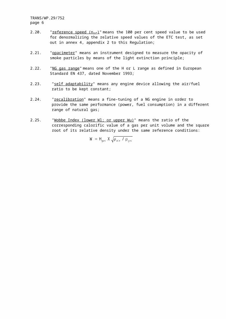
2.20. "reference speed (nref)" means the 100 per cent speed value to be used for denormalizing the relative speed values of the ETC test, as set out in annex 4, appendix 2 to this Regulation;
2.21. "opacimeter" means an instrument designed to measure the opacity of smoke particles by means of the light extinction principle;
2.22. "NG gas range" means one of the H or L range as defined in European Standard EN 437, dated November 1993;
2.23. "self adaptability" means any engine device allowing the air/fuel ratio to be kept constant;
2.24. "recalibration" means a fine-tuning of a NG engine in order to provide the same performance (power, fuel consumption) in a different range of natural gas;
2.25. "Wobbe Index (lower Wl; or upper Wu)" means the ratio of the corresponding calorific value of a gas per unit volume and the square root of its relative density under the same reference conditions:
TRANS/WP.29/752page 6
2.26. "λ-shift factor (Sλ)" means an expression that describes the required flexibility of the engine management system regarding a change of the excess-air ratio λ if the engine is fuelled with a gas composition different from pure methane (see annex 8 for the calculation of Sλ).
2.27. "EEV" means Enhanced Environmentally Friendly Vehicle which is a type of vehicle propelled by an engine complying with the permissive emission limit values given in row C of the Tables in paragraph 5.2.1. of this Regulation;
2.28. "Defeat Device" means any element of engine or vehicle design, which measures or senses vehicle speed, engine speed, gear used, temperature, intake pressure or any other parameter, with a view to activating, modulating delaying or deactivating the operation of any component of the emission control system, so that the effectiveness of the emission control system is reduced under conditions encountered in normal vehicle use.
Such a device will not be regarded as a defeat device if:
2.28.1. the need for the device is justified temporarily to protect the engine against intermittent operating conditions that could lead to damage or failure and no other measures are applicable for the same purpose which do not reduce the effectiveness of the emission control system;
2.28.2. the device operates only when needed during engine starting and/or warming-up and no other measures are applicable for the same purpose which do not reduce the effectiveness of the emission control system.
Figure 1: Specific definitions of the test cycles

TRANS/WP.29/752page 7
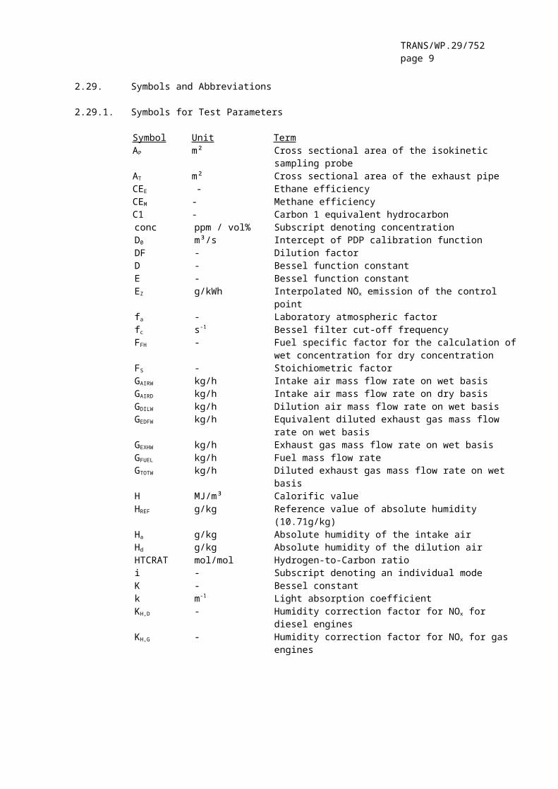
2.29. Symbols and Abbreviations
2.29.1. Symbols for Test Parameters
Symbol Unit TermAP m² Cross sectional area of the isokinetic
sampling probeAT m² Cross sectional area of the exhaust pipeCEE - Ethane efficiencyCEM - Methane efficiencyC1 - Carbon 1 equivalent hydrocarbonconc ppm / vol% Subscript denoting concentration D0 m³/s Intercept of PDP calibration functionDF - Dilution factorD - Bessel function constantE - Bessel function constantEZ g/kWh Interpolated NOx emission of the control
pointfa - Laboratory atmospheric factorfc s-1 Bessel filter cut-off frequencyFFH - Fuel specific factor for the calculation of
wet concentration for dry concentrationFS - Stoichiometric factorGAIRW kg/h Intake air mass flow rate on wet basisGAIRD kg/h Intake air mass flow rate on dry basisGDILW kg/h Dilution air mass flow rate on wet basisGEDFW kg/h Equivalent diluted exhaust gas mass flow
rate on wet basisGEXHW kg/h Exhaust gas mass flow rate on wet basisGFUEL kg/h Fuel mass flow rateGTOTW kg/h Diluted exhaust gas mass flow rate on wet
basisH MJ/m³ Calorific valueHREF g/kg Reference value of absolute humidity
(10.71g/kg)Ha g/kg Absolute humidity of the intake airHd g/kg Absolute humidity of the dilution airHTCRAT mol/mol Hydrogen-to-Carbon ratio i - Subscript denoting an individual modeK - Bessel constantk m-1 Light absorption coefficientKH,D - Humidity correction factor for NOx for
diesel engines
KH,G - Humidity correction factor for NOx for gas engines
KV CFV calibration functionKW,a - Dry to wet correction factor for the intake
airKW,d - Dry to wet correction factor for the
dilution airKW,e - Dry to wet correction factor for the
diluted exhaust gasKW,r - Dry to wet correction factor for the raw
exhaust gasL % Percent torque related to the maximum

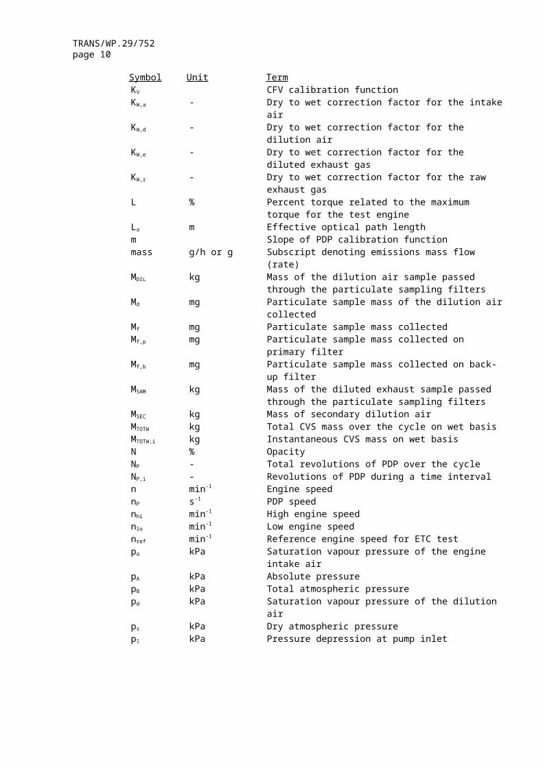
TRANS/WP.29/752page 8
Symbol Unit Termtorque for the test engine
La m Effective optical path lengthm Slope of PDP calibration functionmass g/h or g Subscript denoting emissions mass flow
(rate)MDIL kg Mass of the dilution air sample passed
through the particulate sampling filtersMd mg Particulate sample mass of the dilution air
collectedMf mg Particulate sample mass collectedMf,p mg Particulate sample mass collected on
primary filterMf,b mg Particulate sample mass collected on back-
up filterMSAM kg Mass of the diluted exhaust sample passed
through the particulate sampling filtersMSEC kg Mass of secondary dilution airMTOTW kg Total CVS mass over the cycle on wet basisMTOTW,i kg Instantaneous CVS mass on wet basisN % OpacityNP - Total revolutions of PDP over the cycleNP,i - Revolutions of PDP during a time intervaln min-1 Engine speednP s-1 PDP speednhi min-1 High engine speednlo min-1 Low engine speednref min-1 Reference engine speed for ETC testpa kPa Saturation vapour pressure of the engine
intake airpA kPa Absolute pressurepB kPa Total atmospheric pressurepd kPa Saturation vapour pressure of the dilution
airps kPa Dry atmospheric pressurep1 kPa Pressure depression at pump inletP(a) kW Power absorbed by auxiliaries to be fitted
for test P(b) kW Power absorbed by auxiliaries to be removed
for testP(n) kW Net power non-correctedP(m) kW Power measured on test bed Ω - Bessel constantQs m³/s CVS volume flow rate q - Dilution ratior - Ratio of cross sectional areas of
isokinetic probe and exhaust pipe Ra % Relative humidity of the intake air Rd % Relative humidity of the dilution airRf - FID response factor ρ kg/m³ densityS kW Dynamometer settingSi m-1 Instantaneous smoke valueSλ - λ-shift factorT K Absolute temperature
TRANS/WP.29/752page 9
Symbol Unit TermTa K Absolute temperature of the intake airt s Measuring timete s Electrical response timetf s Filter response time for Bessel functiontp s Physical response timeΔt s Time interval between successive smoke data
(= 1/sampling rate)Δti s Time interval for instantaneous CFV flowτ % Smoke transmittanceV0 m³/rev PDP volume flow rate at actual conditionsW - Wobbe indexWact kWh Actual cycle work of ETCWref kWh Reference cycle work of ETCWF - Weighting factorWFE - Effective weighting factorX0 m³/rev Calibration function of PDP volume flow
rateYi m-1 1 s Bessel averaged smoke value
2.29.2. Symbols for the Chemical Components
CH4 MethaneC2H6 EthaneC3H8 PropaneCO Carbon monoxideDOP Di-octylphtalateCO2 Carbon dioxideHC HydrocarbonsNMHC Non-methane hydrocarbons
NOx Oxides of nitrogenNO Nitric oxideNO2 Nitrogen dioxidePT Particulates
2.29.3. Abbreviations
CFV Critical flow venturiCLD Chemiluminescent detectorELR European Load Response TestESC European Steady State CycleETC European Transient CycleFID Flame Ionisation DetectorGC Gas ChromatographHCLD Heated Chemiluminescent DetectorHFID Heated Flame Ionisation DetectorLPG Liquefied Petroleum GasNDIR Non-Dispersive Infrared AnalyserNG Natural GasNMC Non-Methane Cutter
TRANS/WP.29/752page 10
Paragraph 3.2. , amend to read:
"3.2. Application for approval of a vehicle type in respect of its engine"
Insert new paragraphs 3.3. to 3.2.1. , to read:
"3.3. Application for approval for a vehicle type with an approved engine
3.3.1. The application for approval of a vehicle with regard to emission of gaseous and particulate pollutants by its approved diesel engine or engine family and with regard to the level of the emission of gaseous pollutants by its approved gas engine or engine family must be submitted by the vehicle manufacturer or a duly accredited representative.
3.3.2. It must be accompanied by the necessary documents in triplicate and the following particulars:
3.3.2.1. a description of the vehicle type and of engine-related vehicle parts comprising the particulars referred to in annex 1, as applicable, and a copy of the approval communication form (annex 2a) for the engine or engine family, if applicable, as a separate technical unit which is installed in the vehicle type."
Paragraph 3.3. (former), should be deleted.
Paragraph 4.1. , amend to read:
"4.1. Universal fuel approval
A universal fuel approval is granted subject to the following requirements:
4.1.1. pursuant to paragraphs 3.1. or 3.2. of this Regulation meets the requirements of paragraphs 5 and 6 below, approval of that type of engine or the vehicle must be granted.
4.1.2. In the case of natural gas the parent engine should demonstrate its capability to adapt to any fuel composition that may occur across the market. In the case of natural gas there are generally two types of fuel, high calorific fuel (H-gas) and low calorific fuel (L-gas), but with a significant spread within both ranges; they differ significantly in their energy content expressed by the Wobbe Index and in their λ-shift factor (Sλ). The formulae for the calculation of the Wobbe index and Sλ are given in paragraphs 2.25 and 2.26. The composition of the reference fuels reflects the variations of those parameters.
The parent engine must meet the requirements of this Regulation on the reference fuels G20 and G25, as specified in annex 6, without any readjustment to the fuelling between the two tests. However, one adaptation run over one ETC cycle without measurement is permitted, after the change of the fuel. Before testing, the parent engine must be run-in using the procedure given in paragraph 3 of appendix 2 to annex 4.

TRANS/WP.29/752page 11
4.1.3. In the case of an engine fuelled with natural gas which is self-adaptive for the range of H-gases on the one hand and the range of L-gases on the other hand, and which switches between the H-range and the L-range by means of a switch, the parent engine must be tested on the two relevant reference fuels as specified in annex 6 for each range, at each position of the switch. The fuels are G20 (fuel 1) and G23 (fuel 2) for the H-range of gases, G23 (fuel 1) and G25 (fuel 2) for the L-range of gases. The parent engine must meet the requirements of this Regulation at both positions of the switch without any readjustment to the fuelling between the two tests at each position of the switch. However, one adaptation run over one ETC cycle without measurement is permitted, after the change of the fuel. Before testing the parent engine must be run-in using the procedure given in paragraph 3 of appendix 2 to annex 4.
4.1.3.1. On the manufacturer's request the engine may be tested on a third fuel (fuel 3) if the λ-shift factor (Sλ) lies between those of the fuels G20 and G25, e.g. when fuel 3 is a market fuel. The results of this test may be used as a basis for the evaluation of the conformity of the production.
4.1.3.2. The ratio of emission results "r" must be determined for each pollutant as follows:
or,
and,
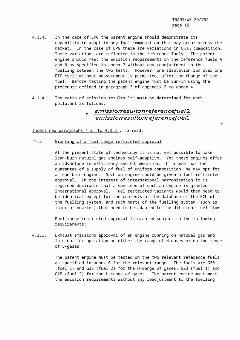
4.1.4. In the case of LPG the parent engine should demonstrate its capability to adapt to any fuel composition that may occur across the market. In the case of LPG there are variations in C3/C4 composition. These variations are reflected in the reference fuels. The parent engine should meet the emission requirements on the reference fuels A and B as specified in annex 7 without any readjustment to the fuelling between the two tests. However, one adaptation run over one ETC cycle without measurement is permitted, after the change of the fuel. Before testing the parent engine must be run-in using the procedure defined in paragraph 3 of appendix 2 to annex 4.
4.1.4.1. The ratio of emission results "r" must be determined for each pollutant as follows:
"

TRANS/WP.29/752page 12
Insert new paragraphs 4.2. to 4.3.2., to read:
"4.2. Granting of a fuel range restricted approval
At the present state of technology it is not yet possible to make lean-burn natural gas engines self-adaptive. Yet these engines offer an advantage in efficiency and CO2 emission. If a user has the guarantee of a supply of fuel of uniform composition, he may opt for a lean-burn engine. Such an engine could be given a fuel-restricted approval. In the interest of international harmonisation it is regarded desirable that a specimen of such an engine is granted international approval. Fuel restricted variants would then need to be identical except for the contents of the database of the ECU of the fuelling system, and such parts of the fuelling system (such as injector nozzles) that need to be adapted to the different fuel flow.
Fuel range restricted approval is granted subject to the following requirements:
4.2.1. Exhaust emissions approval of an engine running on natural gas and laid out for operation on either the range of H-gases or on the range of L-gases
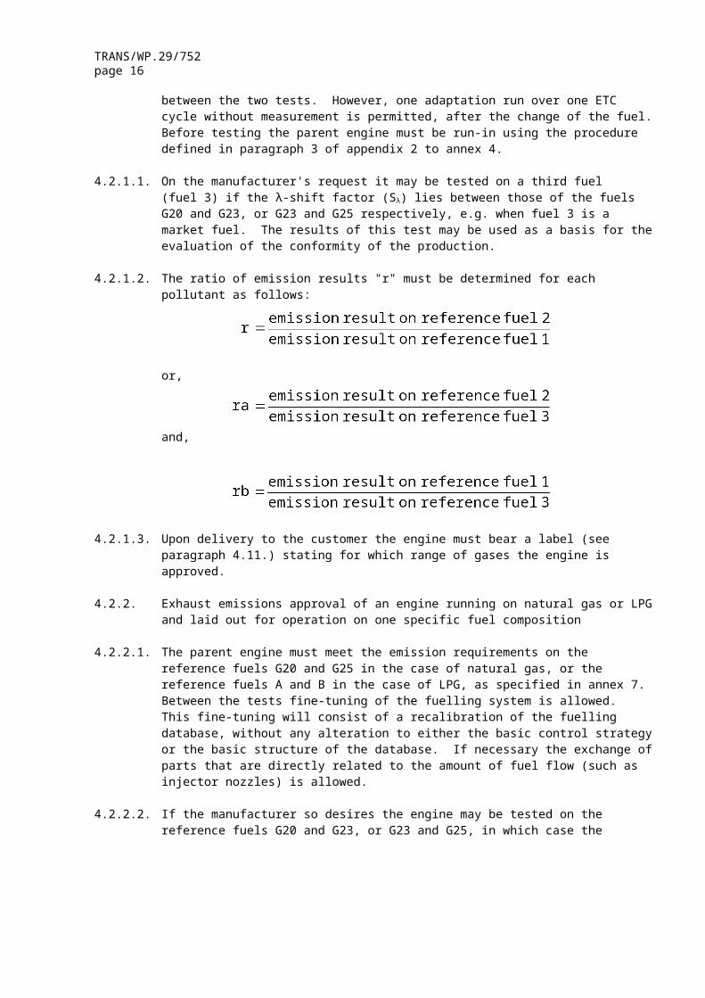
The parent engine must be tested on the two relevant reference fuels as specified in annex 6 for the relevant range. The fuels are G20 (fuel 1) and G23 (fuel 2) for the H-range of gases, G23 (fuel 1) and G25 (fuel 2) for the L-range of gases. The parent engine must meet the emission requirements without any readjustment to the fuelling between the two tests. However, one adaptation run over one ETC cycle without measurement is permitted, after the change of the fuel. Before testing the parent engine must be run-in using the procedure defined in paragraph 3 of appendix 2 to annex 4.
4.2.1.1. On the manufacturer's request it may be tested on a third fuel (fuel 3) if the λ-shift factor (Sλ) lies between those of the fuels G20 and G23, or G23 and G25 respectively, e.g. when fuel 3 is a market fuel. The results of this test may be used as a basis for the evaluation of the conformity of the production.
4.2.1.2. The ratio of emission results "r" must be determined for each pollutant as follows:
or,
and,
TRANS/WP.29/752page 13
4.2.1.3. Upon delivery to the customer the engine must bear a label (see paragraph 4.11.) stating for which range of gases the engine is approved.
4.2.2. Exhaust emissions approval of an engine running on natural gas or LPG and laid out for operation on one specific fuel composition
4.2.2.1. The parent engine must meet the emission requirements on the reference fuels G20 and G25 in the case of natural gas, or the reference fuels A and B in the case of LPG, as specified in annex 7. Between the tests fine-tuning of the fuelling system is allowed. This fine-tuning will consist of a recalibration of the fuelling database, without any alteration to either the basic control strategy or the basic structure of the database. If necessary the exchange of parts that are directly related to the amount of fuel flow (such as injector nozzles) is allowed.
4.2.2.2. If the manufacturer so desires the engine may be tested on the reference fuels G20 and G23, or G23 and G25, in which case the approval is only valid for the H-range or the L-range of gases respectively.
4.2.2.3. Upon delivery to the customer the engine must bear a label (see paragraph 5.1.5.) stating for which fuel composition the engine has been calibrated.
4.3. Exhaust emissions approval of a member of a family
4.3.1. With the exception of the case mentioned in paragraph 4.3.2., the approval of a parent engine must be extended to all family members without further testing, for any fuel composition within the range for which the parent engine has been approved (in the case of engines described in paragraph 4.2.2) or the same range of fuels (in the case of engines described in either paragraphs 4.1. or 4.2) for which the parent engine has been approved.
4.3.2. Secondary test engine
In case of an application for approval of an engine, or a vehicle in respect of its engine, that engine belonging to an engine family, if the approval authority determines that, with regard to the selected parent engine the submitted application does not fully represent the engine family defined in the Regulation, appendix 1, an alternative and, if necessary, an additional reference test engine may be selected by the approval authority and tested."
Paragraph 4.2. (former), renumber as paragraph 4.4., and amend to read:
"4.4. An approval number shall be assigned to each type approved. Its first two digits (at present 03, corresponding to 03 series of amendments which entered into force on [.....]) shall indicate the series ...."
Paragraphs 4.3. and 4.4. (former), renumber as paragraphs 4.5. and 4.6.

TRANS/WP.29/752page 14
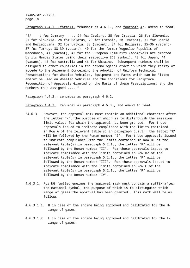
Paragraph 4.4.1. (former), renumber as 4.6.1., and footnote 4/, amend to read:
"4/ 1 for Germany, .... 24 for Ireland, 25 for Croatia, 26 for Slovenia, 27 for Slovakia, 28 for Belarus, 29 for Estonia, 30 (vacant), 31 for Bosnia and Herzegovina, 32 for Latvia, 33 (vacant), 34 for Bulgaria, 35-36 (vacant), 37 for Turkey, 38-39 (vacant), 40 for the former Yugoslav Republic of Macedonia, 41 (vacant), 42 for the European Community (Approvals are granted by its Member States using their respective ECE symbol), 43 for Japan, 44 (vacant), 45 for Australia and 46 for Ukraine. Subsequent numbers shall be assigned to other countries in the chronological order in which they ratify or accede to the Agreement Concerning the Adoption of Uniform Technical Prescriptions for Wheeled Vehicles, Equipment and Parts which can be Fitted and/or be Used on Wheeled Vehicles and the Conditions for Reciprocal Recognition of Approvals Granted on the Basis of these Prescriptions, and the numbers thus assigned ....."
Paragraph 4.4.2., renumber as paragraph 4.6.2.
Paragraph 4.4.3., renumber as paragraph 4.6.3., and amend to read:
"4.6.3. However, the approval mark must contain an additional character after the letter "R", the purpose of which is to distinguish the emission limit values for which the approval has been granted. For those approvals issued to indicate compliance with the limits contained in Row A of the relevant table(s) in paragraph 5.2.1., the letter "R" will be followed by the Roman number "I". For those approvals issued to indicate compliance with the limits contained in Row B1 of the relevant table(s) in paragraph 5.2.1., the letter "R" will be followed by the Roman number "II". For those approvals issued to indicate compliance with the limits contained in Row B2 of the relevant table(s) in paragraph 5.2.1., the letter "R" will be followed by the Roman number "III". For those approvals issued to indicate compliance with the limits contained in Row C of the relevant table(s) in paragraph 5.2.1., the letter "R" will be followed by the Roman number "IV".
4.6.3.1. For NG fuelled engines the approval mark must contain a suffix after the national symbol, the purpose of which is to distinguish which range of gases the approval has been granted. This mark will be as follows;
4.6.3.1.1. H in case of the engine being approved and calibrated for the H-range of gases;
4.6.3.1.2. L in case of the engine being approved and calibrated for the L-range of gases;
4.6.3.1.3. HL in case of the engine being approved and calibrated for both the H-range and L-range of gases;
4.6.3.1.4. Ht in case of the engine being approved and calibrated for a specific gas composition in the H-range of gases and transformable to another specific gas in the H-range of gases by fine tuning of the engine fuelling;
TRANS/WP.29/752page 15
4.6.3.1.5. Lt in case of the engine being approved and calibrated for a specific gas composition in the L-range of gases and transformable to another specific gas in the L-range of gases after fine tuning of the engine fuelling;
4.6.3.1.6. HLt in the case of the engine being approved and calibrated for a specific gas composition in either the H-range or the L-range of gases and transformable to another specific gas in either the H-range or the L-range of gases by fine tuning of the engine fuelling."
Paragraph 4.5. (former), renumber as paragraph 4.7., and amend to read:
"4.7. If the vehicle or engine conforms to an approved type under one or more other Regulations annexed to the Agreement, in the country which has granted approval under this Regulation, the symbol prescribed in paragraph 4.6.1. need not be repeated. In such a case, the Regula-tion and approval numbers and the additional symbols of all the Regu-lations under which approval has been granted under this Regulation shall be placed in vertical columns to the right of the symbol pre-scribed in paragraph 4.6.1."
Paragraphs 4.6. to 4.8.2., renumber as paragraphs 4.9. to 4.10.2.
Paragraph 4.9., renumber as paragraph 4.11., and amend to read:
"4.11. Labels
In the case of NG and LPG fuelled engines with a fuel range restricted type approval, the following labels are applicable:
4.11.1. Content
The following information must be given:
In the case of paragraph 4.2.1.3, the label shall state "ONLY FOR USE WITH NATURAL GAS RANGE H". If applicable, "H" is replaced by "L".
In the case of paragraph 4.2.2.3, the label shall state "ONLY FOR USE WITH NATURAL GAS SPECIFICATION ......." or "ONLY FOR USE WITH LIQUEFIED PETROLEUM GAS SPECIFICATION .........", as applicable. All the information in the relevant table(s) in Annex 6 or 7 shall be given with the individual constituents and limits specified by the engine manufacturer.
The letters and figures must be at least 4 mm in height.
Note:
If lack of space prevents such labelling, a simplified code may be used. In this event, explanatory notes containing all the above information must be easily accessible to any person filling the fuel tank or performing maintenance or repair on the engine and its accessories, as well as to the authorities concerned. The site and content of these explanatory notes will be determined by agreement
TRANS/WP.29/752page 16
between the manufacturer and the approval authority.4.11.2. Properties
Labels must be durable for the useful life of the engine. Labels must be clearly legible and their letters and figures must be indelible. Additionally, labels must be attached in such a manner that their fixing is durable for the useful life of the engine, and the labels cannot be removed without destroying or defacing them.
4.11.3. Placing
Labels must be secured to an engine part necessary for normal engine operation and not normally requiring replacement during engine life. Additionally, these labels must be located so as to be readily visible to the average person after the engine has been completed with all the auxiliaries necessary for engine operation."
Insert new paragraphs 4.12. and 4.13., to read:
"4.12. In case of an application for type-approval for a vehicle type in respect of its engine, the marking specified in paragraph 4.11. must also be placed close to fuel filling aperture.
4.13. In case of an application for type-approval for a vehicle type with an approved engine, the marking specified in paragraph 4.11. must also be placed close to the fuel filling aperture."
Insert new paragraph 5.1.1. , to read:
"5.1.1. The use of a defeat device and/or irrational emissions control strategy is forbidden. If the approval authority suspects that a vehicle type utilises defeat device(s) and/or any irrational emission control strategy under certain operating conditions, upon request the manufacturer has to provide information on the operation and effect on emissions of the use of such devices and/or control strategy. Such information must include a description of all emission control components, fuel control system logic including timing strategies and switch points during all modes of operation. This information should remain strictly confidential and not be attached to the documentation required in paragraph 3."
Paragraph 5.2. , amend to read:
"5.2. For approval to row A of the tables in paragraph 5.2.1., the emissions must be determined on the ESC and ELR tests with conventional diesel engines including those fitted with electronic fuel injection equipment, exhaust gas recirculation (EGR), and/or oxidation catalysts. Diesel engines fitted with advanced exhaust after-treatment systems including deNOx catalysts and/or particulate traps, must additionally be tested on the ETC test.
For approval testing to either row B1 or B2 or row C of the tables in paragraph 5.2.1. the emissions must be determined on the ESC, ELR and ETC tests.

TRANS/WP.29/752page 17
For gas engines, the gaseous emissions must be determined on the ETC test.
The ESC and ELR test procedures are described in annex 4, appendix 1, the ETC test procedure in annex 4, Appendices 2 and 3.
The emissions of gaseous pollutants and particulate pollutants, by the engine submitted for testing, if applicable, must be measured by the method described in annex 4 annex 4, appendix 4 describes ....."
Paragraph 5.2.1. , amend to read:
"5.2.1. Limit Values
The specific mass of the carbon monoxide, of the total hydrocarbons, of the oxides of nitrogen and of the particulates, as determined on the ESC test, and of the smoke opacity, as determined on the ELR test, must not exceed the amounts shown in Table 1.For diesel engines that are additionally tested on the ETC test, and specifically for gas engines, the specific masses of the carbon monoxide, of the non-methane hydrocarbons, of the methane (where applicable), of the oxides of nitrogen and of the particulates (where applicable) must not exceed the amounts shown in Table 2.
Table 1 Limit values – ESC and ELR tests
Row
Mass ofCarbonMonoxide(CO)g/kWh
Mass ofHydrocarbons
(HC)g/kWh
Mass ofNitrogenoxides(NOx)g/kWh
Mass ofparticulates
(PT)g/kWh
Smoke
m-1
A (2000) 2.1 0.66 5.0 0.10 0.13(a) 0.8
B1 (2005) 1.5 0.46 3.5 0.02 0.5B2 (2008) 1.5 0.46 2.0 0.02 0.5C (EEV) 1.5 0.25 2.0 0.02 0.15
(a) For engines having a swept volume of less than 0.75 dm3 per cylinder and a rated power speed of more than 3000 min-1.
Table 2 Limit values – ETC tests (b)
Row
Mass ofCarbon
monoxide(CO)g/kWh
Mass ofNon-methanehydrocarbons
(NMHC)g/kWh
Mass ofmethane
(CH4)(c)
g/kWh
Mass ofNitrogenoxides(NOx)g/kWh
Mass ofparticulates
(PT)(d)
g/kWh)
A (2000) 5.45 0.78 1.6 5.0 0.16 0.21(a)
B1 (2005) 4.0 0.55 1.1 3.5 0.03B2 (2008) 4.0 0.55 1.1 2.0 0.03C (EEV) 3.0 0.40 0.65 2.0 0.02
TRANS/WP.29/752page 18
(a) For engines having a swept volume of less than 0.75 dm3 per cylinder and a rated power speed of more than 3000 min-1.
(b) The conditions for verifying the acceptability of the ETC tests (see annex 4, appendix 2, paragraph 3.9.) when measuring the emissions of gas fuelled engines against the limit values applicable in row A must be re-examined and, where necessary, modified in accordance with the procedure laid down in Consolidated Resolution R.E.3.
(c) For NG engines only.
(d) Not applicable for gas fuelled engines at stage A and stages B1 and B2 ."
Insert new paragraphs 5.2.2. to 5.2.3.2., to read:
"5.2.2. Hydrocarbon measurement for diesel and gas fuelled engines
5.2.2.1. A manufacturer may choose to measure the mass of total hydrocarbons (THC) on the ETC test instead of measuring the mass of non-methane hydrocarbons. In this case, the limit for the mass of total hydrocarbons is the same as shown in table 2 for the mass of non-methane hydrocarbons.
5.2.3. Specific requirements for diesel engines
5.2.3.1. The specific mass of the oxides of nitrogen measured at the random check points within the control area of the ESC test must not exceed by more than 10 per cent the values interpolated from the adjacent test modes (reference annex 4, appendix 1 paragraphs 4.6.2. and 4.6.3.).
5.2.3.2. The smoke value on the random test speed of the ELR must not exceed the highest smoke value of the two adjacent test speeds by more than 20 per cent, or by more than 5 per cent of the limit value, whichever is greater."
Paragraph 6.1.3. , amend to read:
"6.1.3. power absorbed by the auxiliaries needed for operating the engine must not exceed that specified for the type-approved engine in annex 2A."
Insert new paragraphs 7. to 7.2.2. , to read:
"7. ENGINE FAMILY
7.1. Parameters defining the engine family
The engine family, as determined by the engine manufacturer, may be defined by basic characteristics, which must be common to engines within the family. In some cases there may be interaction of parameters. These effects must also be taken into consideration to ensure that only engines with similar exhaust emission characteristics are included within an engine family.

TRANS/WP.29/752page 19
In order that engines may be considered to belong to the same engine family, the following list of basic parameters must be common:
7.1.1. Combustion cycle:
– 2 cycle– 4 cycle
7.1.2. Cooling medium:
– air– water– oil
7.1.3. For gas engines and engines with after-treatment
– Number of cylinders
(other diesel engines with fewer cylinders than the parent engine may be considered to belong to the same engine family provided the fuelling system meters fuel for each individual cylinder).
7.1.4. Individual cylinder displacement:
– engines to be within a total spread of 15 per cent
7.1.5. Method of air aspiration:
– naturally aspirated– pressure charged– pressure charged with charge air cooler
7.1.6. Combustion chamber type/design:
– pre-chamber– swirl chamber– open chamber
7.1.7. Valve and porting - configuration, size and number:
– cylinder head– cylinder wall– crankcase
7.1.8. Fuel injection system (diesel engines):
– pump-line-injector– in-line pump– distributor pump– single element– unit injector

TRANS/WP.29/752page 20
7.1.9. Fuelling system (gas engines):
– mixing unit– gas induction/injection (single point, multi-point)– liquid injection (single point, multi-point)
7.1.10. Ignition system (gas engines)
7.1.11. Miscellaneous features:
– exhaust gas recirculation– water injection/emulsion– secondary air injection– charge cooling system
7.1.12. Exhaust after treatment:
– 3-way-catalyst– oxidation catalyst– reduction catalyst– thermal reactor– particulate trap
7.2. Choice of the parent engine
7.2.1. Diesel engines
The parent engine of the family must be selected using the primary criteria of the highest fuel delivery per stroke at the declared maximum torque speed. In the event that two or more engines share this primary criteria, the parent engine must be selected using the secondary criteria of highest fuel delivery per stroke at rated speed. Under certain circumstances, the approval authority may conclude that the worst case emission rate of the family can best be characterised by testing a second engine. Thus, the approval authority may select an additional engine for test based upon features, which indicate that it may have the highest emission level of the engines within that family.
If engines within the family incorporate other variable features, which could be considered to affect exhaust emissions, these features must also be identified and taken into account in the selection of the parent engine.
7.2.2. Gas engines
The parent engine of the family must be selected using the primary criteria of the largest displacement. In the event that two or more engines share this primary criteria, the parent engine must be selected using the secondary criteria in the following order:
– the highest fuel delivery per stroke at the speed of declared rated power;
– the most advanced spark timing;– the lowest EGR rate;

TRANS/WP.29/752page 21
– no air pump or lowest actual air flow pump.
Under certain circumstances, the approval authority may conclude that the worst case emission rate of the family can best be characterised by testing a second engine. Thus, the approval authority may select an additional engine for test based upon features, which indicate that it may have the highest emission level of the engines within that family."
Paragraphs 7. to 7.4.4., replace by the following text (paragraphs 8. to 8.3.2.6., including also new Figure 2):
"8. CONFORMITY OF PRODUCTION
The conformity of production procedures shall comply with those set out in the Agreement, appendix 2 (E/ECE/324-E/ECE/TRANS/505/Rev.2), with the following requirements:
8.1. Every engine or vehicle bearing an approval mark as prescribed under this Regulation shall be so manufactured as to conform, with regard to the description as given in the approval form and its annexes, to the approved type.
8.2. As a general rule, conformity of production with regard to limitation of emissions is checked based on the description given in the communication form and its annexes.
8.3. If emissions of pollutants are to be measured and an engine approval has had one or several extensions, the tests will be carried out on the engine(s) described in the information package relating to the relevant extension.
8.3.1. Conformity of the engine subjected to a pollutant test:
After submission of the engine to the authorities, the manufacturer must not carry out any adjustment to the engines selected.
8.3.1.1. Three engines are randomly taken in the series. Engines that are subject to testing only on the ESC and ELR tests or only on the ETC test for approval to row A of the tables in paragraph 5.2.1. are subject to those applicable tests for the checking of production conformity. With the agreement of the authority, all other engines approved to row A, B1 or B2, or C of the tables in paragraph 5.2.1. are subjected to testing either on the ESC and ELR cycles or on the ETC cycle for the checking of the production conformity. The limit values are given in paragraph 5.2.1. of the Regulation.
8.3.1.2. The tests are carried out according to appendix 1 to this Regulation, where the competent authority is satisfied with the production standard deviation given by the manufacturer.
The tests are carried out according to appendix 2 to this Regulation, where the competent authority is not satisfied with the production standard deviation given by the manufacturer.

TRANS/WP.29/752page 22
At the manufacturer's request, the tests may be carried out in accordance with appendix 3 to this Regulation.
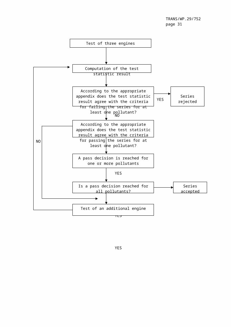
8.3.1.3. On the basis of a test of the engine by sampling, the production of a series is regarded as conforming where a pass decision is reached for all the pollutants and non conforming where a fail decision is reached for one pollutant, in accordance with the test criteria applied in the appropriate appendix.
When a pass decision has been reached for one pollutant, this decision may not be changed by any additional tests made in order to reach a decision for the other pollutants.
If no pass decision is reached for all the pollutants and if no fail decision is reached for one pollutant, a test is carried out on another engine (see figure 2).
If no decision is reached, the manufacturer may at any time decide to stop testing. In that case a fail decision is recorded.
8.3.2. The tests will be carried out on newly manufactured engines. Gas fuelled engines must be run-in using the procedure defined in paragraph 3 of appendix 2 to annex 4.
8.3.2.1. However, at the request of the manufacturer, the tests may be carried out on diesel or gas engines which have been run-in more than the period referred to in paragraph 8.4.2.2., up to a maximum of 100 hours. In this case, the running-in procedure will be conducted by the manufacturer who must undertake not to make any adjustments to those engines.
8.3.2.2. When the manufacturer asks to conduct a running-in procedure in accordance with paragraph 8.4.2.2.1., it may be carried out on:
– all the engines that are tested,
or,
– the first engine tested, with the determination of an evolution coefficient as follows:
– the pollutant emissions will be measured at zero and at "x" hours on the first engine tested,
– the evolution coefficient of the emissions between zero and "x" hours will be calculated for each pollutant:
It may be less than one.
The subsequent test engines will not be subjected to the running-in procedure, but their zero hour emissions will be modified by the evolution coefficient.

TRANS/WP.29/752page 23
In this case, the values to be taken will be:
– the values at "x" hours for the first engine,
- the values at zero hour multiplied by the evolution coefficient for the other engines.
8.3.2.3 For diesel and LPG fuelled engines, all these tests may be conducted with commercial fuel. However, at the manufacturer's request, the reference fuels described in annexes 5 or 7 may be used. This implies tests, as described in paragraph 4. of this Regulation, with at least two of the reference fuels for each gas engine.
8.3.2.4. For NG fuelled engines, all these tests may be conducted with commercial fuel in the following way:
▪ for H marked engines with a commercial fuel within the H range;
▪ for L marked engines with a commercial fuel within the L range;
▪ for HL marked engines with a commercial fuel within the H or the L range.
However, at the manufacturer's request, the reference fuels described in annex 6 may be used. This implies tests, as described in paragraph 4. of this Regulation, with at least two of the reference fuels for each gas engine.
8.3.2.5. In the case of dispute caused by the non-compliance of gas fuelled engines, when using a commercial fuel, the tests must be performed with a reference fuel on which the parent engine has been tested, or with the possible additional fuel 3 as referred to in paragraphs 4.1.3.1. and 4.2.1.1., on which the parent engine may have been tested. Then, the result has to be converted by a calculation applying the relevant factor(s) "r", "ra" or "rb" as described in paragraphs 4.1.3.2., 4.1.4.1. and 4.2.1.2. If r, ra or rb are less than one no correction must take place. The measured results and the calculated results must demonstrate that the engine meets the limit values with all relevant fuels (fuels 1, 2 and, if applicable, fuel 3).
8.3.2.6. Tests for conformity of production of a gas fuelled engine laid out for operation on one specific fuel composition must be performed on the fuel for which the engine has been calibrated.

TRANS/WP.29/752page 24
YES
NO
NO
NO
YES
YES
YES
YES
YES
Figure 2: Conformity of production testing scheme"
Paragraphs 8. (former) to 10, renumber as paragraphs 9. to 11.
Test of three engines
Computation of the test statistic result
According to the appropriate appendix does the test statistic result agree with the criteria for failing the series for at least one pollutant?
Series rejected
According to the appropriate appendix does the test statistic result agree with the criteria for passing the series for at least one pollutant?
A pass decision is reached for one or more pollutants
Is a pass decision reached for all pollutants? Series accepted
Test of an additional engine

TRANS/WP.29/752page 25
Paragraph 11. (former), renumber as paragraph 12. and amend to read:
"12. TRANSITIONAL PROVISIONS
12.1. General
12.1.1. As from the official date of entry into force of the 03 series of amendments, no Contracting Party applying this Regulation must refuse to grant ECE approval under this Regulation as amended by the 03 series of amendments.
12.1.2. As from the date of entry into force of the 03 series of amendments, Contracting Parties applying this Regulation must grant ECE approvals only if the engine meets the requirements of this Regulation as amended by the 03 series of amendments.
The engine must be subject to the relevant tests set out in paragraph 5.2. to this Regulation and must, in accordance with paragraphs 12.2.1., 12.2.2. and 12.2.3. below, satisfy the relevant emission limits detailed in paragraph 5.2.1. of this Regulation.
12.2. New type approvals
12.2.1. Subject to the provisions of paragraph 12.4.1., Contracting Parties applying this Regulation must, from the date of entry into force of the 03 series of amendments to this Regulation, grant an ECE approval to an engine only if that engine satisfies the relevant emission limits of Rows A, B1, B2 or C in the tables to paragraph 5.2.1. of this Regulation.
12.2.2. Subject to the provisions of paragraph 12.4.1., Contracting Parties applying this Regulation must, from 1 October 2005, grant an ECE approval to an engine only if that engine satisfies the relevant emission limits of Rows B1, B2 or C in the tables to paragraph 5.2.1. of this Regulation.
12.2.3. Subject to the provisions of paragraph 12.4.1., Contracting Parties applying this Regulation must, from 1 October 2008, grant an ECE approval to an engine only if that engine satisfies the relevant emission limits of Rows B2 or C in the tables to paragraph 5.2.1. of this Regulation.
12.3. Limit of validity of old type approvals
12.3.1. As from 1 October 2001, type approvals granted to this Regulation as amended by the 02 series of amendments must cease to be valid, unless the Contracting Party which granted the approval notifies the other Contracting Parties applying this Regulation that the engine type approved meets the requirements of this Regulation as amended by the 03 series of amendments, in accordance with paragraph 12.2.1. above.
12.3.2. As from 1 October 2006, type approvals granted to this Regulation as amended by the 03 series of amendments must cease to be valid, unless the Contracting Party which granted the approval notifies the other

TRANS/WP.29/752page 26
Contracting Parties applying this Regulation that the engine type approved meets the requirements of this Regulation as amended by the 03 series of amendments, in accordance with paragraph 12.2.2. above.
12.3.3. As from 1 October 2009, type approvals granted to this Regulation as amended by the 03 series of amendments must cease to be valid, unless the Contracting Party which granted the approval notifies the other Contracting Parties applying this Regulation that the engine type approved meets the requirements of this Regulation as amended by the 03 series of amendments, in accordance with paragraph 12.2.3. above.
12.4. Replacement parts for vehicles in use
12.4.1. Contracting Parties applying this Regulation may continue to grant approvals to those engines which comply with the requirements of this Regulation as amended by any previous series of amendments, or to any level of the Regulation as amended by the 03 series of amendments, provided that the engine is intended as a replacement for a vehicle in-use and for which that earlier standard was applicable at the date of that vehicle’s entry into service."
Paragraph 12.(former), renumber as paragraph 13.
Add to the Regulation new Appendices 1 to 3, to read:
"Appendix 1
PROCEDURE FOR PRODUCTION CONFORMITY TESTINGWHEN STANDARD DEVIATION IS SATISFACTORY
1. This appendix describes the procedure to be used to verify production conformity for the emissions of pollutants when the manufacturer's production standard deviation is satisfactory.
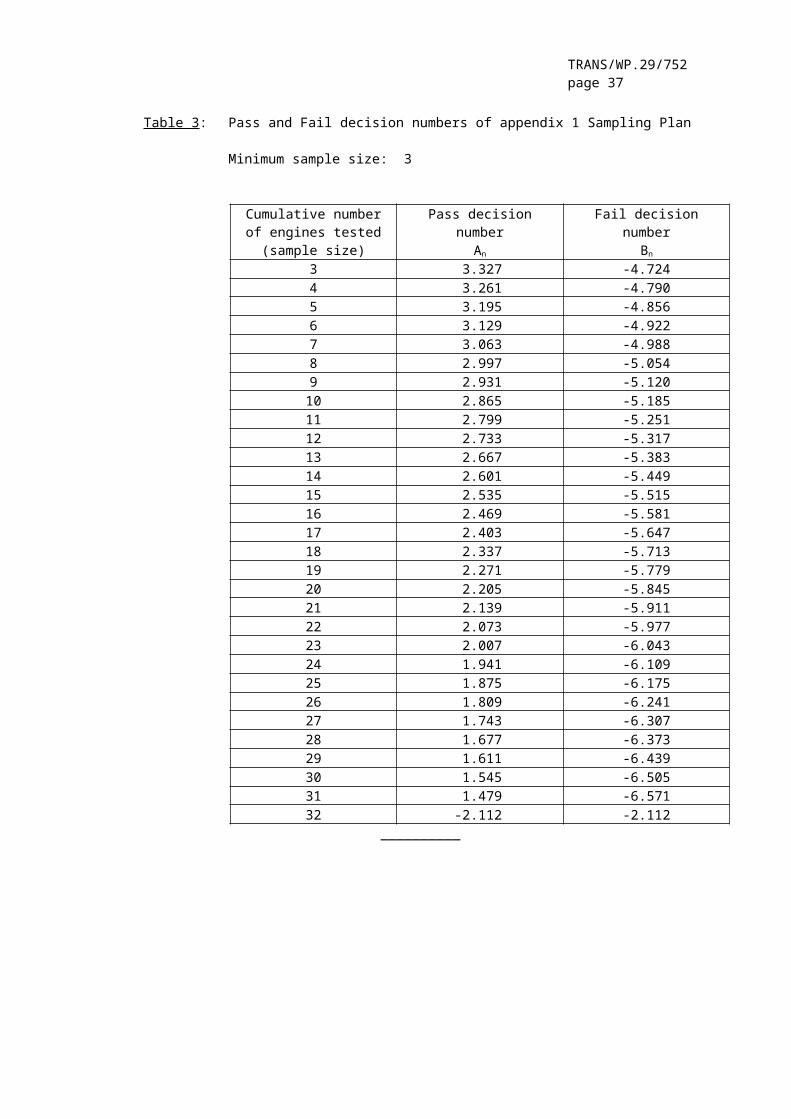
2. With a minimum sample size of three engines, the sampling procedure is set so that the probability of a lot passing a test with 40 per cent of the engines defective is 0.95 (producer's risk = 5 per cent), while the probability of a lot being accepted with 65 per cent of the engines defective is 0.10 (consumer's risk = 10 per cent).
3. The following procedure is used for each of the pollutants given in paragraph 5.2.1. of the Regulation (see Figure 2):
Let:
L = the natural logarithm of the limit value for the pollutant;
xi = the natural logarithm of the measurement for the i-th engine of the sample;
s = an estimate of the production standard deviation (after taking the natural logarithm of the measurements);
n = the current sample number.
TRANS/WP.29/752page 27
4. For each sample the sum of the standardised deviations to the limit is calculated using the following formula:
5. Then:
– if the test statistic result is greater than the pass decision number for the sample size given in table 3, a pass decision is reached for the pollutant;
– if the test statistic result is less than the fail decision number for the sample size given in table 3, a fail decision is reached for the pollutant;
– otherwise, an additional engine is tested according to paragraph 8.4.2.1. of the Regulation and the calculation procedure is applied to the sample increased by one more unit.

TRANS/WP.29/752page 28
Table 3: Pass and Fail decision numbers of appendix 1 Sampling Plan
Minimum sample size: 3
Cumulative numberof engines tested(sample size)
Pass decisionnumber
An
Fail decisionnumber
Bn
3 3.327 -4.7244 3.261 -4.7905 3.195 -4.8566 3.129 -4.9227 3.063 -4.9888 2.997 -5.0549 2.931 -5.12010 2.865 -5.18511 2.799 -5.25112 2.733 -5.31713 2.667 -5.38314 2.601 -5.44915 2.535 -5.51516 2.469 -5.58117 2.403 -5.64718 2.337 -5.71319 2.271 -5.77920 2.205 -5.84521 2.139 -5.91122 2.073 -5.97723 2.007 -6.04324 1.941 -6.10925 1.875 -6.17526 1.809 -6.24127 1.743 -6.30728 1.677 -6.37329 1.611 -6.43930 1.545 -6.50531 1.479 -6.57132 -2.112 -2.112
__________

TRANS/WP.29/752page 29
Appendix 2
PROCEDURE FOR PRODUCTION CONFORMITY TESTINGWHEN STANDARD DEVIATION IS UNSATISFACTORY OR UNAVAILABLE
1. This appendix describes the procedure to be used to verify production conformity for the emissions of pollutants when the manufacturer's production standard deviation is either unsatisfactory or unavailable.
2. With a minimum sample size of three engines, the sampling procedure is set so that the probability of a lot passing a test with 40 per cent of the engines defective is 0.95 (producer's risk = 5 per cent), while the probability of a lot being accepted with 65 per cent of the engines defective is 0.10 (consumer's risk = 10 per cent).
3. The values of the pollutants given in paragraph 5.2.1. of the Regulation are considered to be log normally distributed and should be transformed by taking their natural logarithms.Let m0 and m denote the minimum and maximum sample size respectively (m0 = 3 and m = 32) and let n denote the current sample number.
4. If the natural logarithms of the values measured in the series are x1, x2, ..., xi and L is the natural logarithm of the limit value for the pollutant, then, define
di = xi – Land,
5. Table 4 shows values of the pass (An) and fail (Bn) decision numbers
against current sample number. The test statistic result is the
ratio and must be used to determine whether the series has
passed or failed as follows:
For m0 ≤ n ≤ m :
– pass the series if
– fail the series if
– take another measurement if

TRANS/WP.29/752page 30
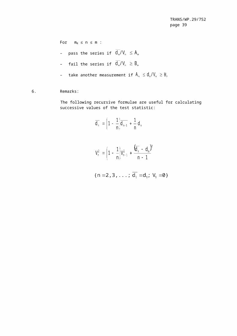
6. Remarks:
The following recursive formulae are useful for calculating successive values of the test statistic:
TRANS/WP.29/752page 31
Table 4: Pass and Fail decision numbers of appendix 2 Sampling Plan
Minimum sample size: 3
Cumulative numberof engines tested(sample size)
Pass decisionnumber
An
Fail decisionnumber
Bn
3 -0.80381 16.647434 -0.76339 7.686275 -0.72982 4.671366 -0.69962 3.255737 -0.67129 2.454318 -0.64406 1.943699 -0.61750 1.5910510 -0.59135 1.3329511 -0.56542 1.1356612 -0.53960 0.9797013 -0.51379 0.8530714 -0.48791 0.7480115 -0.46191 0.6592816 -0.43573 0.5832117 -0.40933 0.5171818 -0.38266 0.4592219 -0.35570 0.4078820 -0.32840 0.3620321 -0.30072 0.3207822 -0.27263 0.2834323 -0.24410 0.2494324 -0.21509 0.2183125 -0.18557 0.1897026 -0.15550 0.1632827 -0.12483 0.1388028 -0.09354 0.1160329 -0.06159 0.0948030 -0.02892 0.0749331 -0.00449 0.0562932 0.03876 0.03876
__________

TRANS/WP.29/752page 32
Appendix 3
PROCEDURE FOR PRODUCTION CONFORMITY TESTINGAT MANUFACTURER'S REQUEST
1. This appendix describes the procedure to be used to verify, at the manufacturer's request, production conformity for the emissions of pollutants.
2. With a minimum sample size of three engines, the sampling procedure is set so that the probability of a lot passing a test with 30 per cent of the engines defective is 0.90 (producer's risk = 10 per cent), while the probability of a lot being accepted with 65 per cent of the engines defective is 0.10 (consumer's risk = 10 per cent).
3. The following procedure is used for each of the pollutants given in Paragraph 5.2.1. of the Regulation (see figure 2):
Let:
L = the limit value for the pollutant,
xi = the value of the measurement for the i-th engine of the sample,
n = the current sample number.
4. Calculate for the sample the test statistic quantifying the number of non-conforming engines, i.e. xi ≥ L:
5. Then:
– if the test statistic is less than or equal to the pass decision number for the sample size given in table 5, a pass decision is reached for the pollutant;
– if the test statistic is greater than or equal to the fail decision number for the sample size given in table 5, a fail decision is reached for the pollutant;
– otherwise, an additional engine is tested according to paragraph 8.4.2.1. of the Regulation and the calculation procedure is applied to the sample increased by one more unit.
In table 5 the pass and fail decision numbers are calculated by means of the International Standard ISO 8422:1991.

TRANS/WP.29/752page 33
Table 5: Pass and Fail decision numbers of appendix 3 Sampling Plan
Minimum sample size: 3
Cumulative number ofengines tested(sample size)
Pass decision number Fail decision number
3 - 34 0 45 0 46 1 57 1 58 2 69 2 610 3 711 3 712 4 813 4 814 5 915 5 916 6 1017 6 1018 7 1119 8 9
__________ "
Annex 1, amend to read:
"Annex 1
ESSENTIAL CHARACTERISTICS OF THE (PARENT) ENGINE AND INFORMATIONCONCERNING THE CONDUCT OF TEST (1)
1. DESCRIPTION OF ENGINE
1.1. Manufacturer:......................................................1.2. Manufacturer's engine code:........................................1.3. Cycle: four stroke / two stroke(2) 1.4. Number and arrangement of cylinders:...............................1.4.1. Bore: ...........................................................mm1.4.2. Stroke:..........................................................mm1.4.3. Firing order:......................................................1.5. Engine capacity: ...............................................cm³1.6. Volumetric compression ratio(3) :...................................1.7. Drawing(s) of combustion chamber and piston crown: ................1.8. Minimum cross-sectional area of inlet and outlet ports: ........cm²1.9. Idling speed: .................................................min-1
1.10. Maximum net power: ........kW at ..............................min-1
1.11. Maximum permitted engine speed:................................min-1
1.12. Maximum net torque: ........Nm at ............................min-1 1.13. Combustion system: compression ignition/positive ignition(2)
TRANS/WP.29/752page 34
1.14. Fuel: Diesel/LPG/NG-H/NG-L/NG-HL(2)
1.15. Cooling system1.15.1. Liquid1.15.1.1. Nature of liquid: .................................................1.15.1.2. Circulating pump(s): yes/no(2)
1.15.1.3. Characteristics or make(s) and type(s) (if applicable):............1.15.1.4. Drive ratio(s) (if applicable): ...................................1.15.2. Air1.15.2.1. Blower: yes/no (2)
1.15.2.2. Characteristics or make(s) and type(s) (if applicable):............1.15.2.3. Drive ratio(s) (if applicable):....................................1.16. Temperature permitted by the manufacturer1.16.1. Liquid cooling: Maximum temperature at outlet:....................K1.16.2. Air cooling: ............ Reference point: ......................
Maximum temperature at reference point: ..........................K1.16.3. Maximum temperature of the air at the outlet of the intake
intercooler (if applicable).......................................K1.16.4. Maximum exhaust temperature at the point in the exhaust pipe(s)
adjacent to the outer flange(s) of the exhaust manifold(s)or turbocharger(s):...............................................K
1.16.5. Fuel temperature: min. .................K, max. ..................Kfor diesel engines at injection pump inlet, for gas fuelled engines at pressure regulator final stage.
1.16.6. Fuel pressure: min. ......................kPa, max. ............kPaat pressure regulator final stage, NG fuelled gas engines only.
1.16.7. Lubricant temperature: min. ..................K, max. ............K1.17 Pressure charger: yes/no(2)
1.17.1. Make:..............................................................1.17.2. Type:..............................................................1.17.3. ..........................................Description of the system
(e.g. max. charge pressure, wastegate, if applicable):.............1.17.4. Intercooler: yes/no (2)
1.18. Intake systemMaximum allowable intake depression at rated engine speed and at 100 per cent load as specified in and under the operating conditionsof Regulation No. 24........................................... kPa
1.19. Exhaust system Maximum allowable exhaust back pressure at rated engine speed and at 100 per cent load as specified in and under the operating conditions
of Regulation No. 24............................................kPaExhaust system volume: .........................................dm³
2. MEASURES TAKEN AGAINST AIR POLLUTION
2.1. Device for recycling crankcase gases (description and drawings):........................................................................
2.2. Additional anti-pollution devices (if any, and if not covered by another heading)
2.2.1. Catalytic converter: yes/no (2)
2.2.1.1. Make(s):...........................................................2.2.1.2. Type(s):...........................................................2.2.1.3. Number of catalytic converters and elements:.......................2.2.1.4. Dimensions, shape and volume of the catalytic converter(s):........

TRANS/WP.29/752page 35
2.2.1.5. Type of catalytic action:..........................................2.2.1.6. Total charge of precious metals:...................................2.2.1.7. Relative concentration:............................................2.2.1.8. Substrate (structure and material):................................2.2.1.9. Cell density:......................................................2.2.1.10. Type of casing for the catalytic converter(s):.....................2.2.1.11. Location of the catalytic converter(s) (place and reference
distance in the exhaust line): .......................................................................................................
2.2.2. Oxygen sensor: yes/no(2)
2.2.2.1. Make(s):...........................................................2.2.2.2. Type:..............................................................2.2.2.3. Location:..........................................................2.2.3. Air injection: yes/no(2)
2.2.3.1. Type (pulse air, air pump, etc.): .................................2.2.4. EGR: yes/no (2) 2.2.4.1. Characteristics (flow rate, etc.):.................................2.2.5. Particulate trap: yes/no (2)
2.2.5.1. Dimensions, shape and capacity of the particulate trap:............2.2.5.2. Type and design of the particulate trap:...........................2.2.5.3. Location (reference distance in the exhaust line):.................2.2.5.4. Method or system of regeneration, description and/or drawing:......2.2.6 . Other systems: yes/no(2)
2.2.6.1. Description and operation:.........................................
3. FUEL FEED
3.1. Diesel engines3.1.1. Feed pump
Pressure(3) : .........kPa or characteristic diagram(2):.............3.1.2. Injection system3.1.2.1. Pump3.1.2.1.1. Make(s):...........................................................3.1.2.1.2. Type(s):...........................................................3.1.2.1.3. Delivery: ......mm³(3) per stroke at engine speed of.......rpm at
full injection, or characteristic diagram(2) (3): ......................................................................................Mention the method used: On engine/on pump bench(2)
If boost control is supplied, state the characteristic fuel delivery and boost pressure versus engine speed.
3.1.2.1.4. Injection advance3.1.2.1.4.1.Injection advance curve (3):........................................3.1.2.1.4.2.Static injection timing (3):........................................3.1.2.2. Injection piping3.1.2.2.1. Length:..........................................................mm3.1.2.2.2. Internal diameter:...............................................mm3.1.2.3. Injector(s)3.1.2.3.1. Make(s):...........................................................3.1.2.3.2. Type(s):...........................................................3.1.2.3.3. "Opening pressure":...........................................kPa(3)
or characteristic diagram (2)(3):....................................3.1.2.4. Governor3.1.2.4.1. Make(s):...........................................................3.1.2.4.2. Type(s):...........................................................3.1.2.4.3. Speed at which cut-off starts under full load: .................rpm

TRANS/WP.29/752page 36
3.1.2.4.4. Maximum no-load speed: .........................................rpm3.1.2.4.5. Idling speed: ..................................................rpm3.1.3. Cold start system3.1.3.1. Make(s): ..........................................................3.1.3.2. Type(s):...........................................................3.1.3.3. Description:.......................................................3.1.3.4. Auxiliary starting aid:............................................3.1.3.4.1. Make:..............................................................3.1.3.4.2. Type:..............................................................3.2. Gas fuelled engines(6)
3.2.1. Fuel: Natural gas/LPG (2)
3.2.2. Pressure regulator(s) or vaporiser/pressure regulator(s) (3)
3.2.2.1. Make(s):...........................................................3.2.2.2. Type(s):...........................................................3.2.2.3. Number of pressure reduction stages:...............................3.2.2.4. Pressure in final stage: min................kPa, max. ..........kPa3.2.2.5. Number of main adjustment points: .................................3.2.2.6. Number of idle adjustment points: .................................3.2.2.7. Approval number according to Reg. ***: ............................3.2.3. Fuelling system: mixing unit / gas injection / liquid injection /
direct injection(2)
3.2.3.1. Mixture strength regulation: ......................................3.2.3.2. System description and/or diagram and drawings: ...................3.2.3.3. Approval number according to Regulation No. .......................3.2.4. Mixing unit3.2.4.1. Number: ...........................................................3.2.4.2. Make(s):...........................................................3.2.4.3. Type(s):...........................................................3.2.4.4. Location:..........................................................3.2.4.5. Adjustment possibilities:..........................................3.2.4.6. Approval number according to Regulation No. .......................3.2.5. Inlet manifold injection3.2.5.1. Injection: single point / multi-point ((2)
3.2.5.2. Injection : continuous / simultaneously timed /sequentially timed (2)
3.2.5.3. Injection equipment3.2.5.3.1. Make(s): ..........................................................3.2.5.3.2. Type(s): ..........................................................3.2.5.3.3. Adjustment possibilities:..........................................3.2.5.3.4. Approval number according to Regulation No. .......................3.2.5.4. Supply pump (if applicable):.......................................3.2.5.4.1. Make(s): ..........................................................3.2.5.4.2. Type(s): ..........................................................3.2.5.4.3. Approval number according to Regulation No. .......................3.2.5.5. Injector(s): ......................................................3.2.5.5.1. Make(s): ..........................................................3.2.5.5.2. Type(s):...........................................................3.2.5.5.3. Approval number according to Regulation No. .......................3.2.6. Direct injection3.2.6.1. Injection pump / pressure regulator (2)
3.2.6.1.1. Make(s):...........................................................3.2.6.1.2. Type(s):...........................................................3.2.6.1.3. Injection timing: .................................................3.2.6.1.4. Approval number according to Regulation No. .......................3.2.6.2. Injector(s)
TRANS/WP.29/752page 37
3.2.6.2.1. Make(s): ..........................................................3.2.6.2.2. Type(s): ..........................................................3.2.6.2.3. Opening pressure or characteristic diagram (3): ....................3.2.6.2.4. Approval number according to Regulation No. .......................3.2.7. Electronic control unit (ECU)3.2.7.1. Make(s): ..........................................................3.2.7.2. Type(s): ..........................................................3.2.7.3. Adjustment possibilities:..........................................3.2.8. NG fuel-specific equipment3.2.8.1. Variant 1 (only in the case of approvals of engines for several
specific fuel compositions)3.2.8.1.1. Fuel composition:
methane (CH4): basis:....%mole min.....%mole max.....%moleethane (C2H6): basis:....%mole min.....%mole max.....%molepropane (C3H8): basis:....%mole min.....%mole max.....%molebutane (C4H10): basis:....%mole min.....%mole max.....%moleC5/C5+: basis:....%mole min.....%mole max.....%moleoxygen (O2): basis:....%mole min.....%mole max.....%moleinert (N2, He etc): basis:....%mole min.....%mole max.....%mole
3.2.8.1.2. Injector(s)3.2.8.1.2.1.Make(s): 3.2.8.1.2.2.Type(s): 3.2.8.1.3. Others (if applicable)3.2.8.2. Variant 2 (only in the case of approvals for several specific fuel
compositions)
4. VALVE TIMING
4.1. Maximum lift of valves and angles of opening and closing in relation to dead centres or equivalent data .....................................
4.2. Reference and/or setting ranges (2) : ...................................
5. IGNITION SYSTEM (SPARK IGNITION ENGINES ONLY)
5.1. Ignition system type:common coil and plugs / individual coil and plugs / coil on plug / other (specify) (2)
5.2. Ignition control unit5.2.1. Make(s): ..............................................................5.2.2. Type(s): ..............................................................5.3. Ignition advance curve / advance map (2) (3)
: .....................................................................
5.4. Ignition timing (3): ...degrees before TDC at a speed of .......... rpm and a MAP of ................. kPa
5.5. Spark plugs5.5.1. Make(s): ..............................................................5.5.2. Type(s): ..............................................................5.5.3. Gap setting: ........................................................mm5.6. Ignition coil(s)5.6.1. Make(s): ..............................................................5.6.2. Type(s): ..............................................................

TRANS/WP.29/752page 38
6. ENGINE-DRIVEN EQUIPMENT
The engine must be submitted for testing with the auxiliaries needed for operating the engine (e.g. fan, water pump, etc.), as specified in and under the operating conditions of Regulation No. 24.
6.1. Auxiliaries to be fitted for the test
If it is impossible or inappropriate to install the auxiliaries on the test bench, the power absorbed by them must be determined and subtracted from the measured engine power over the whole operating area of the test cycle(s).
6.2. Auxiliaries to be removed for the test
Auxiliaries needed only for the operation of the vehicle (e.g. air compressor, air-conditioning system etc.) must be removed for the test. Where the auxiliaries cannot be removed, the power absorbed by them may be determined and added to the measured engine power over the whole operating area of the test cycle(s).
7. ADDITIONAL INFORMATION ON TEST CONDITIONS
7.1. Lubricant used7.1.1. Make: .................................................................7.1.2. Type: .................................................................
(State percentage of oil in mixture if lubricant and fuel are mixed): .....................................................
7.2. Engine-driven equipment (if applicable)The power absorbed by the auxiliaries needs only be determined, – if auxiliaries needed for operating the engine, are not fitted to the
engine and/or– if auxiliaries not needed for operating the engine, are fitted to the
engine. 7.2.1. Enumeration and identifying details: ..................................
7.2.2. Power absorbed at various indicated engine speeds:
Equipment Power absorbed (kW) at various engine speedsIdle Low Speed High Speed Speed A(7) Speed B(7) Speed C(7) Ref. Speed(8)
P(a)Auxiliaries needed for operating the engine(to be subtracted from measured engine power)see item 6.1.
P(b)Auxiliaries not needed for operating the engine(to be added to measured engine power)see item 6.2.
TRANS/WP.29/752page 39
8. ENGINE PERFORMANCE
8.1. Engine speeds (9)
Low speed (nlo): ...................................................rpmHigh speed (nhi): ..................................................rpm
for ESC and ELR CyclesIdle: .............................................................rpmSpeed A: ..........................................................rpmSpeed B: ..........................................................rpmSpeed C: ..........................................................rpmfor ETC cycleReference speed: ..................................................rpm
8.2. Engine power (measured in accordance with the provisions of Regulation No. 24) in kW
Engine speed
Idle Speed A (7) Speed B (7) Speed C (7) Ref. Speed (8)
P(m)Power measured on test bed
P(a)Power absorbed by auxiliaries to be fitted for test (item 6.1)- if fitted- if not fitted 0 0 0 0 0
P(b)Power absorbed by auxiliaries to be removed for test (item 6.2)- if fitted- if not fitted 0 0 0 0 0
P(n)Net engine power = P(m) - P(a) + P(b)
8.3. Dynamometer settings (kW)
The dynamometer settings for the ESC and ELR tests and for the reference cycle of the ETC test must be based upon the net engine power P(n) of paragraph 8.2. It is recommended to install the engine on the test bed in the net condition. In this case, P(m) and P(n) are identical. If it is impossible or inappropriate to operate the engine under net conditions, the dynamometer settings must be corrected to net conditions using the above formula.

TRANS/WP.29/752page 40
8.3.1. ESC and ELR Tests
The dynamometer settings must be calculated according to the formula in annex 4, appendix 1, paragraph 1.2.
Per cent load Engine speed
Idle Speed A Speed B Speed C10 --25 --50 --75 --100
8.3.2. ETC Test
If the engine is not tested under net conditions, the correction formula for converting the measured power or measured cycle work, as determined according to annex 4, appendix 2, paragraph 2., to net power or net cycle work must be submitted by the engine manufacturer for the whole operating area of the cycle, and approved by the Technical Service.
Footnotes:
(1) In the case of non-conventional engines and systems, particulars equivalent to those referred to here must be supplied by the manufacturer.
(2) Strike out what does not apply.
(3) Specify the tolerance.
(6) In the case of systems laid out in a different manner, supply equivalent information (for paragraph 3.2).
(7) ESC test
(8) ETC test only.
(9) Specify the tolerance; to be within ± 3 per cent of the values declared by the manufacturer.
__________"
TRANS/WP.29/752page 41
Annex 1 – Appendix, rename as annex 1 – appendix 1, and amend to read:
"Annex 1 – Appendix 1
CHARACTERISTICS OF THE ENGINE-RELATED VEHICLE PARTS
1. Intake system depression at rated engine speed andat 100 per cent load: ............................................kPa
2. Exhaust system back pressure at rated engine speed andat 100 per cent load: ............................................kPa
3. Volume of exhaust system: ........................................cm³
4. Power absorbed by the auxiliaries needed for operating the engine as specified in and under the operation conditions of Regulation No. 24
Equipment Power absorbed (kW) at various engine speeds
Idle Low Speed High Speed Speed A(1) Speed B(1) Speed C(1) Ref. Speed (2) P(a)
Auxiliaries needed for operating the engine(to be subtracted from measured engine power)see annex 1, item 6.1.
(1) ESC test(2) ETC test only.
__________"
Insert new Annex 1 – Appendices 2 and 3, to read:
"Annex 1 – Appendix 2
ESSENTIAL CHARACTERISTICS OF THE ENGINE FAMILY
1. COMMON PARAMETERS
1.1. Combustion cycle: .....................................................
1.2. Cooling medium: .......................................................
1.3. Number of cylinders (1).................................................
1.4. Individual cylinder displacement: .....................................
1.5. Method of air aspiration: .............................................
1.6. Combustion chamber type/design: .......................................

TRANS/WP.29/752page 42
1.7. Valve and porting - configuration, size and number: ..........................................................................................
1.8. Fuel system: ..........................................................
1.9. Ignition system (gas engines): ........................................
1.10. Miscellaneous features:
- charge cooling system (1): ...........................................- exhaust gas recirculation (1): .......................................- water injection/emulsion (1): ........................................- air injection (1).....................................................
1.11. Exhaust after-treatment (1): ............................................
Proof of identical (or lowest for the parent engine) ratio:system capacity / fuel delivery per stroke, pursuant to diagram number(s): ..................................................
2. ENGINE FAMILY LISTING
2.1. Name of diesel engine family: .........................................
2.1.1. Specification of engines within this family:
Parent EngineEngine TypeNo. of cylinders
Rated speed (rpm)
Fuel delivery per stroke (mm³)
Rated net power (kW)
Maximum torque speed (rpm)
Fuel delivery per stroke (mm³)
Maximum torque (Nm)
Low idle speed (rpm)
Cylinder displacement(in % of parent engine) 100

TRANS/WP.29/752page 43
2.2. Name of gas engine family: ............................................
2.2.1 Specification of engines within this family:
Parent EngineEngine TypeNo. of cylinders
Rated speed (rpm)
Fuel delivery per stroke (mg)
Rated net power (kW)
Maximum torque speed (rpm)
Fuel delivery per stroke (mm³)
Maximum torque (Nm)
Low idle speed (rpm)
Cylinder displacement(in % of parent engine) 100
Spark timing
EGR flow
Air pump yes / no
Air pump actual flow
(1) If not applicable, mark "N/A"
__________
Annex 1 - Appendix 3
ESSENTIAL CHARACTERISTICS OF THE ENGINE TYPEWITHIN THE FAMILY (1)
1. DESCRIPTION OF ENGINE
1.1. Manufacturer: ...................................................1.2. Manufacturer's engine code: .....................................1.3. Cycle: four stroke / two stroke (2) 1.4. Number and arrangement of cylinders: ............................1.4.1. Bore: .........................................................mm1.4.2. Stroke: .......................................................mm1.4.3. Firing order: ...................................................1.5. Engine capacity: .............................................cm³1.6. Volumetric compression ratio (3): ................................1.7. Drawing(s) of combustion chamber and piston crown: ..............
.................................................................1.8. Minimum cross-sectional area of inlet and outlet
ports: ..............................................................cm²
1.9. Idling speed: ...............................................min-1
1.10. Maximum net power: ..................kW at ..................min-1
1.11. Maximum permitted engine speed: .............................min-1

TRANS/WP.29/752page 44
1.12. Maximum net torque: .................Nm at ..................min-1
1.13. Combustion system: compression ignition/positive ignition (2)
1.14. Fuel: Diesel/LPG/NG-H/NG-L/NG-HL (2)
1.15. Cooling system1.15.1. Liquid1.15.1.1. Nature of liquid: ...............................................1.15.1.2. Circulating pump(s): yes/no (2)
1.15.1.3. Characteristics or make(s) and type(s) (if applicable): ..........................................................................
1.15.1.4. Drive ratio(s) (if applicable): .................................1.15.2. Air1.15.2.1. Blower: yes/no (2) 1.15.2.2. Characteristics or make(s) and type(s) (if applicable): .........
.................................................................1.15.2.3. Drive ratio(s) (if applicable): .................................1.16. Temperature permitted by the manufacturer1.16.1. Liquid cooling: Maximum temperature at outlet: .................K1.16.2. Air cooling: Reference point: ...............................
Maximum temperature at reference point: ....................K1.16.3. Maximum temperature of the air at the outlet of the intake
intercooler (if applicable): ...................................K1.16.4. Maximum exhaust temperature at the point in the exhaust pipe(s)
adjacent to the outer flange(s) of the exhaust manifold(s) or turbocharger(s): ...............................................K
1.16.5. Fuel temperature: min. ..............K, max. ................Kfor diesel engines at injection pump inlet, for NG fuelled gas engines at pressure regulator final stage
1.16.6. Fuel pressure: min. ..............kPa, max. ...............kPaat pressure regulator final stage, NG fuelled gas engines only
1.16.7. Lubricant temperature: min. .............K, max..............K1.17. Pressure charger: yes/no (2) 1.17.1. Make: ...........................................................1.17.2. Type: ...........................................................1.17.3. Description of the system (e.g. max. charge pressure, wastegate,
if applicable): ..................................1.17.4. Intercooler: yes/no (2) 1.18. Intake system
Maximum allowable intake depression at rated engine speed and at 100 per cent load as specified in and under the operating conditions of Regulation No. 24: .............................kPa
1.19. Exhaust system Maximum allowable exhaust back pressure at rated engine speed and at 100 per cent load as specified in and under the operating conditions of Regulation No. 24: .............................kPaExhaust system volume: .......................................cm³
2. MEASURES TAKEN AGAINST AIR POLLUTION
2.1. Device for recycling crankcase gases (description and drawings): .................................................................
2.2. Additional anti-pollution devices (if any, and if not covered by another heading)
2.2.1. Catalytic converter: yes/no (2)
2.2.1.1. Number of catalytic converters and elements: ....................

TRANS/WP.29/752page 45
2.2.1.2. Dimensions, shape and volume of the catalytic converter(s): ......................................................................
2.2.1.3. Type of catalytic action: .......................................2.2.1.4. Total charge of precious metals: ................................2.2.1.5. Relative concentration: .........................................2.2.1.6. Substrate (structure and material): .............................2.2.1.7. Cell density: ...................................................2.2.1.8. Type of casing for the catalytic converter(s): ..................2.2.1.9. Location of the catalytic converter(s) (place and reference
distance in the exhaust line): ...................................................................................................
2.2.2. Oxygen sensor: yes/no (2)
2.2.2.1. Type: ...........................................................2.2.3. Air injection: yes/no (2)
2.2.3.1. Type (pulse air, air pump, etc.): ...............................2.2.4. EGR: yes/no (2) 2.2.4.1. Characteristics (flow rate etc.): ...............................2.2.5. Particulate trap: yes/no (2)
2.2.5.1. Dimensions, shape and capacity of the particulate trap: ..........................................................................
2.2.5.2. Type and design of the particulate trap: ........................2.2.5.3. Location (reference distance in the exhaust line): ..............2.2.5.4. Method or system of regeneration, description and/or drawing: ...
.................................................................2.2.6. Other systems: yes/no (2)
2.2.6.1. Description and operation: ......................................
3. FUEL FEED
3.1. Diesel engines3.1.1. Feed pump
Pressure (3): ..............kPa or characteristic diagram (2): .....................................................................
3.1.2. Injection system3.1.2.1. Pump3.1.2.1.1. Make(s): ........................................................3.1.2.1.2. Type(s): ........................................................3.1.2.1.3. Delivery: ......mm³ (3) per stroke at engine speed of..........rpm
at full injection, or characteristic diagram (2) (3): ..............................................................................Mention the method used: On engine / on pump bench (2)
If boost control is supplied, state the characteristic fuel delivery and boost pressure versus engine speed.
3.1.2.1.4. Injection advance3.1.2.1.4.1. Injection advance curve (3): .....................................3.1.2.1.4.2. Static injection timing (3): .....................................3.1.2.2. Injection piping3.1.2.2.1. Length: .......................................................mm3.1.2.2.2. Internal diameter: ............................................mm3.1.2.3. Injector(s)3.1.2.3.1. Make(s): ....................................................... 3.1.2.3.2. Type(s): ....................................................... 3.1.2.3.3. "Opening pressure": ........................................kPa(3)
or characteristic diagram(2) (3): .................................3.1.2.4. Governor
TRANS/WP.29/752page 46
3.1.2.4.1. Make(s): ....................................................... 3.1.2.4.2. Type(s): ........................................................3.1.2.4.3. Speed at which cut-off starts under full load: ...............rpm3.1.2.4.4. Maximum no-load speed: .......................................rpm3.1.2.4.5. Idling speed: ................................................rpm3.1.3. Cold start system3.1.3.1. Make(s): ........................................................3.1.3.2. Type(s): ........................................................3.1.3.3. Description: ....................................................3.1.3.4. Auxiliary starting aid: .........................................3.1.3.4.1. Make: ...........................................................3.1.3.4.2. Type: ...........................................................3.2. Gas fuelled engines3.2.1. Fuel: Natural gas/LPG (2)
3.2.2. Pressure regulator(s) or vaporiser/pressure regulator(s)(2)
3.2.2.1. Make(s): ........................................................3.2.2.2. Type(s): ........................................................3.2.2.3. Number of pressure reduction stages: ............................3.2.2.4. Pressure in final stage: min. .........kPa, max. ..........kPa3.2.2.5. Number of main adjustment points: ...............................3.2.2.6. Number of idle adjustment points: ...............................3.2.2.7. Approval number: ................................................3.2.3. Fuelling system: mixing unit / gas injection / liquid injection /
direct injection (2)
3.2.3.1. Mixture strength regulation: ....................................3.2.3.2. System description and/or diagram and drawings: .................
.................................................................3.2.3.3. Approval number: ................................................3.2.4. Mixing unit3.2.4.1. Number: .........................................................3.2.4.2. Make(s): ........................................................3.2.4.3. Type(s): ........................................................3.2.4.4. Location: .......................................................3.2.4.5. Adjustment possibilities: .......................................3.2.4.6. Approval number: ................................................3.2.5. Inlet manifold injection3.2.5.1. Injection: single point / multi-point (2)
3.2.5.2. Injection : continuous / simultaneously timed / sequentially timed (2)
3.2.5.3. Injection equipment3.2.5.3.1. Make(s): ........................................................3.2.5.3.2. Type(s): ........................................................3.2.5.3.3. Adjustment possibilities: .......................................3.2.5.3.4. Approval number: ................................................3.2.5.4. Supply pump (if applicable): ....................................3.2.5.4.1. Make(s): ........................................................3.2.5.4.2. Type(s): ........................................................3.2.5.4.3. Approval number: ................................................3.2.5.5. Injector(s):.....................................................3.2.5.5.1. Make(s): ........................................................3.2.5.5.2. Type(s): ........................................................3.2.5.5.3. Approval number: ................................................3.2.6. Direct injection3.2.6.1. Injection pump / pressure regulator (2)
3.2.6.1.1. Make(s): ........................................................

TRANS/WP.29/752page 47
3.2.6.1.2. Type(s): ........................................................3.2.6.1.3. Injection timing: ...............................................3.2.6.1.4. Approval number: ................................................3.2.6.2. Injector(s)3.2.6.2.1. Make(s): ........................................................3.2.6.2.2. Type(s): ........................................................3.2.6.2.3. Opening pressure or characteristic diagram (3): ..................
.................................................................3.2.6.2.4. Approval number: ................................................3.2.7. Electronic control unit (ECU)3.2.7.1. Make(s): ........................................................3.2.7.2. Type(s): ........................................................3.2.7.3. Adjustment possibilities: .......................................3.2.8. NG fuel-specific equipment3.2.8.1. Variant 1 (only in the case of approvals of engines for several
specific fuel compositions)3.2.8.1.1. Fuel composition:
methane (CH4): basis:....%mole min.....%mole max.....%moleethane (C2H6): basis:....%mole min.....%mole max.....%molepropane (C3H8): basis:....%mole min.....%mole max.....%molebutane (C4H10): basis:....%mole min.....%mole max.....%moleC5/C5+: basis:....%mole min.....%mole max.....%moleoxygen (O2): basis:....%mole min.....%mole max.....%moleinert (N2, He etc): basis:....%mole min.....%mole max.....%mole
3.2.8.1.2. Injector(s)3.2.8.1.2.1. Make(s): ........................................................3.2.8.1.2.2. Type(s): ........................................................3.2.8.1.3. Others (if applicable)3.2.8.2. Variant 2 (only in the case of approvals for several specific
fuel compositions)
4. VALVE TIMING
4.1. Maximum lift of valves and angles of opening and closing in relation to dead centres of equivalent data: .....................................................................................
4.2. Reference and/or setting ranges (2) : .............................................................................................
5. IGNITION SYSTEM (SPARK IGNITION ENGINES ONLY)
5.1. Ignition system type: common coil and plugs / individual coil and plugs / coil on plug / other (specify) (2)
5.2. Ignition control unit5.2.1. Make(s): ........................................................5.2.2. Type(s): ........................................................5.2. Ignition advance curve / advance map (2)(3): ......................
.................................................................5.4. Ignition timing (3): ...............degrees before TDC at a speed
of ................ rpm and a MAP of ........................ kPa5.5. Spark plugs5.5.1. Make(s): ........................................................5.5.2. Type(s): ........................................................

TRANS/WP.29/752page 48
5.5.3. Gap setting: ..................................................mm5.6. Ignition coil(s)5.6.1. Make(s): ........................................................5.6.2. Type(s): ........................................................Footnotes
(1) To be submitted for each engine of the family.
(2) Strike out what does not apply.
(3) Specify the tolerance.
__________"
Annex 3, amend to read:
"Annex 3
ARRANGEMENTS OF APPROVAL MARKS(See paragraph 4.6. of this Regulation)
I. APPROVAL “I” (Row A).(See paragraph 4.6.3. of this Regulation)
Model A
Engines approved to Row A emission limits and operating on diesel or liquefied petroleum gas (LPG) fuel.
Model B
Engines approved to Row A emission limits and operating on natural gas (NG) fuel. The suffix after the national symbol indicates the fuel qualification determined in accordance with paragraph 4.6.3.1. of this Regulation.
The above approval marks affixed to an engine/vehicle show that the engine/vehicle type concerned has been approved in the United Kingdom (E11) pursuant to Regulation No. 49 and under approval number 032439.

TRANS/WP.29/752page 49
This approval indicates that the approval was given in accordance with the requirements of Regulation No. 49 with the 03 series of amendments incorporated and satisfying the relevant limits detailed in paragraph 5.2.1. of this Regulation.
II. APPROVAL “II” (Row B1).(See paragraph 4.6.3. of this Regulation)
Model C
Engines approved to Row B1 emission limits and operating on diesel or liquefied petroleum gas (LPG) fuel.
Model D
Engines approved to Row B1 emission limits and operating on natural gas (NG) fuel. The suffix after the national symbol indicates the fuel qualification determined in accordance with paragraph 4.6.3.1. of this Regulation.
The above approval mark affixed to an engine/vehicle shows that the engine/vehicle type concerned has been approved in the United Kingdom (E11) pursuant to Regulation No. 49 and under approval number 032439. This approval indicates that the approval was given in accordance with the requirements of Regulation No. 49 with the 03 series of amendments incorporated and satisfying the relevant limits detailed in paragraph 5.2.1. of this Regulation.
III. APPROVAL “III” (Row B2).(See paragraph 4.6.3. of this Regulation)
Model E
Engines approved to Row B2 emission limits and operating on diesel or liquefied petroleum gas (LPG) fuel.

TRANS/WP.29/752page 50
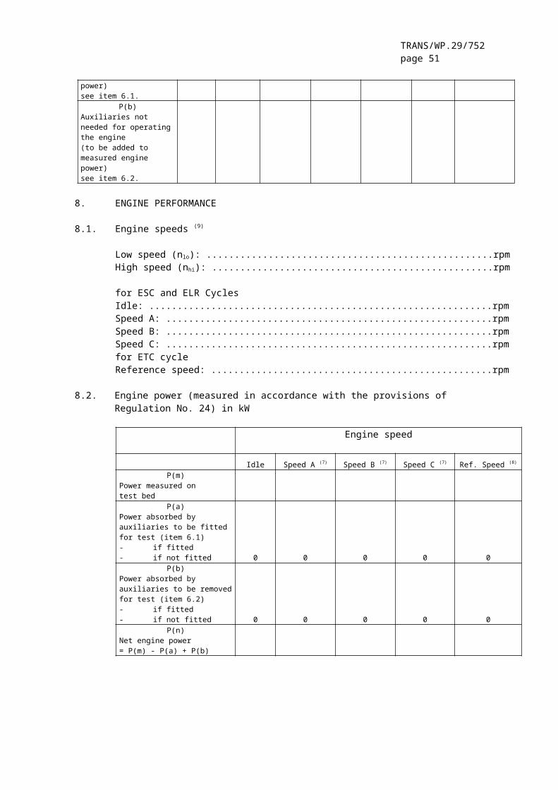
TRANS/WP.29/752page 51
Model F
Engines approved to Row B2 emission limits and operating on natural gas (NG) fuel. The suffix after the national symbol indicates the fuel qualification determined in accordance with paragraph 4.6.3.1. of this Regulation.
The above approval mark affixed to an engine/vehicle shows that the engine/vehicle type concerned has been approved in the United Kingdom (E11) pursuant to Regulation No. 49 and under approval number 032439. This approval indicates that the approval was given in accordance with the requirements of Regulation No. 49 with the 03 series of amendments incorporated and satisfying the relevant limits detailed in paragraph 5.2.1. of this Regulation.
IV. APPROVAL “IV” (Row C).(See paragraph 4.6.3. of this Regulation)
Model G
Engines approved to Row C emission limits and operating on diesel or liquefied petroleum gas (LPG) fuel.
Model H
Engines approved to Row C emission limits and operating on natural gas (NG) fuel. The suffix after the national symbol indicates the fuel qualification determined in accordance with paragraph 4.6.3.1. of this Regulation.
The above approval mark affixed to an engine/vehicle shows that the engine/vehicle type concerned has been approved in the United Kingdom

TRANS/WP.29/752page 52
(E11) pursuant to Regulation No. 49 and under approval number 032439. This approval indicates that the approval was given in accordance with the requirements of Regulation No. 49 with the 03 series of amendments incorporated and satisfying the relevant limits detailed in paragraph 5.2.1. of this Regulation.
V. ENGINE/VEHICLE APPROVED TO ONE OR MORE REGULATIONS(See paragraph 4.7. of this Regulation)
Model I
The above approval mark affixed to an engine/vehicle shows that the engine/vehicle type concerned has been approved in the United Kingdom (E11) pursuant to Regulation No. 49 (emission level IV) and Regulation No. 24. The first two digits of the approval numbers indicate that, at the dates when the respective approvals were given, Regulation No. 49 included the 03 series of amendments, as did Regulation No. 24.
__________
1/ The second Regulation number is given merely as an example; the corrected absorption coefficient is 1.30 m-1.
__________"
Annex 4, amend to read:
"Annex 4
TEST PROCEDURE
1. INTRODUCTION
1.1. This annex describes the methods of determining emissions of gaseous components, particulates and smoke from the engines to be tested. Three test cycles are described that must be applied according to the provisions of the Regulation, paragraph 6.2:
1.1.1. the ESC which consists of a steady state 13-mode cycle,
1.1.2. the ELR which consists of transient load steps at different speeds, which are integral parts of one test procedure, and are run concurrently;
1.1.3. the ETC which consists of a second-by-second sequence of transient modes.

TRANS/WP.29/752page 53
1.2. The test must be carried out with the engine mounted on a test bench and connected to a dynamometer.
1.3. Measurement principle
The emissions to be measured from the exhaust of the engine include the gaseous components (carbon monoxide, total hydrocarbons for diesel engines on the ESC test only; non-methane hydrocarbons for diesel and gas engines on the ETC test only; methane for gas engines on the ETC test only and oxides of nitrogen), the particulates (diesel engines only) and smoke (diesel engines on the ELR test only). Additionally, carbon dioxide is often used as a tracer gas for determining the dilution ratio of partial and full flow dilution systems. Good engineering practice recommends the general measurement of carbon dioxide as an excellent tool for the detection of measurement problems during the test run.
1.3.1. ESC test
During a prescribed sequence of warmed-up engine operating conditions the amounts of the above exhaust emissions must be examined continuously by taking a sample from the raw exhaust gas. The test cycle consists of a number of speed and power modes, which cover the typical operating range of diesel engines. During each mode the concentration of each gaseous pollutant, exhaust flow and power output must be determined, and the measured values weighted. The particulate sample must be diluted with conditioned ambient air. One sample over the complete test procedure must be taken, and collected on suitable filters. The grams of each pollutant emitted per kilowatt-hour (kWh) must be calculated as described in appendix 1 to this annex. Additionally, NOx must be measured at three test points within the control area selected by the Technical Service 1 and the measured values compared to the values calculated from those modes of the test cycle enveloping the selected test points. The NOx control check ensures the effectiveness of the emission control of the engine within the typical engine operating range.
1.3.2. ELR test
During a prescribed load response test, the smoke of a warmed-up engine must be determined by means of an opacimeter. The test consists of loading the engine at constant speed from 10 per cent to 100 per cent load at three different engine speeds. Additionally, a fourth load step selected by the Technical Service 1 must be run, and the value compared to the values of the previous load steps. The smoke peak must be determined using an averaging algorithm, as described in appendix 1 to this annex.
1.3.3. ETC test
During a prescribed transient cycle of warmed-up engine operating conditions, which is based closely on road-type-specific driving patterns of heavy-duty engines installed in trucks and buses, the above
1 The test points must be selected using approved statistical methods of randomisation.

TRANS/WP.29/752page 54
pollutants must be examined after diluting the total exhaust gas with conditioned ambient air. Using the engine torque and speed feedback signals of the engine dynamometer, the power must be integrated with respect to time of the cycle resulting in the work produced by the engine over the cycle. The concentration of NOx and HC must be determined over the cycle by integration of the analyser signal. The concentration of CO, CO2, and NMHC may be determined by integration of the analyser signal or by bag sampling. For particulates, a proportional sample must be collected on suitable filters. The diluted exhaust gas flow rate must be determined over the cycle to calculate the mass emission values of the pollutants. The mass emission values must be related to the engine work to get the grams of each pollutant emitted per kilowatt-hour (kWh), as described in appendix 2 to this annex.
2. TEST CONDITIONS
2.1. Engine test conditions
2.1.1. The absolute temperature (Ta) of the engine air at the inlet to the engine expressed in Kelvins, and the dry atmospheric pressure (ps), expressed in kPa must be measured and the parameter F must be determined according to the following provisions:
(a) for diesel engines:
Naturally aspirated and mechanically supercharged engines:
Turbocharged engines with or without cooling of the intake air:
(b) for gas engines:
2.1.2. Test validity
For a test to be recognised as valid, the parameter F must be such that:
0.96 ≤ F ≤ 1.06

TRANS/WP.29/752page 55
2.2. Engines with charge air cooling
The charge air temperature must be recorded and must be, at the speed of the declared maximum power and full load, within ± 5 K of the maximum charge air temperature specified in annex 1, appendix 1, paragraph 1.16.3. The temperature of the cooling medium must be at least 293 K (20°C).
If a test shop system or external blower is used, the charge air temperature must be within ± 5 K of the maximum charge air temperature specified in annex 1, appendix 1, paragraph 1.16.3. at the speed of the declared maximum power and full load. The setting of the charge air cooler for meeting the above conditions must be used for the whole test cycle.
2.3. Engine air intake system
An engine air intake system must be used presenting an air intake restriction within ± 100 Pa of the upper limit of the engine operating at the speed at the declared maximum power and full load.
2.4. Engine exhaust system
An exhaust system must be used presenting an exhaust back pressure within ± 1000 Pa of the upper limit of the engine operating at the speed of declared maximum power and full load and a volume within ± 40 per cent of that specified by the manufacturer. A test shop system may be used, provided it represents actual engine operating conditions. The exhaust system must conform to the requirements for exhaust gas sampling, as set out in annex 4, appendix 4, paragraph 3.4. and in annex 4, appendix 7, paragraph 2.2.1., EP and paragraph 2.3.1., EP.
If the engine is equipped with an exhaust after-treatment device, the exhaust pipe must have the same diameter as found in-use for at least 4 pipe diameters upstream to the inlet of the beginning of the expansion paragraph containing the after-treatment device. The distance from the exhaust manifold flange or turbocharger outlet to the exhaust after-treatment device must be the same as in the vehicle configuration or within the distance specifications of the manufacturer. The exhaust back-pressure or restriction must follow the same criteria as above, and may be set with a valve. The after-treatment container may be removed during dummy tests and during engine mapping, and replaced with an equivalent container having an inactive catalyst support.
2.5. Cooling system
An engine cooling system with sufficient capacity to maintain the engine at normal operating temperatures prescribed by the manufacturer must be used.

TRANS/WP.29/752page 56
2.6 Lubricating oil
Specifications of the lubricating oil used for the test must be recorded and presented with the results of the test, as specified in annex 1, appendix 1, paragraph 7.1.
2.7. Fuel
The fuel must be the reference fuel specified in annexes 5, 5 or 7.
The fuel temperature and measuring point must be specified by the manufacturer within the limits given in annex 1, appendix 1, paragraph 1.16.5. The fuel temperature must not be lower than 306 K (33°C). If not specified, it must be 311 K ± 5 K (38°C ± 5°C) at the inlet to the fuel supply.
For NG and LPG fuelled engines, the fuel temperature and measuring point must be within the limits given in annex 1, appendix 1, paragraph 1.16.5. or in annex 1, appendix 3, paragraph 1.16.5. in cases where the engine is not a parent engine.
2.8. Testing of exhaust after-treatment systems
If the engine is equipped with an exhaust after-treatment system, the emissions measured on the test cycle(s) must be representative of the emissions in the field. If this cannot be achieved with one single test cycle (e.g. for particulate filters with periodic regeneration), several test cycles must be conducted and the test results averaged and/or weighted. The exact procedure must be agreed by the engine manufacturer and the Technical Service based upon good engineering judgement.
__________"
Annex 4 – Appendix 1, amend to read:
"Annex 4 - Appendix 1
ESC AND ELR TEST CYCLES
1. ENGINE AND DYNAMOMETER SETTINGS
1.1. Determination of engine speeds A, B and C
The engine speeds A, B and C must be declared by the manufacturer in accordance with the following provisions:
The high speed nhi must be determined by calculating 70 per cent of the declared maximum net power P(n), as determined in annex 1, appendix 1, paragraph 8.2. The highest engine speed where this power value occurs on the power curve is defined as nhi.
The low speed nlo must be determined by calculating 50 per cent of the declared maximum net power P(n), as determined in annex 1, appendix 1,

TRANS/WP.29/752page 57
paragraph 8.2. The lowest engine speed where this power value occurs on the power curve is defined as nlo.The engine speeds A, B and C must be calculated as follows:
Speed A = nlo + 25 % (nhi - nlo )Speed B = nlo + 50 % (nhi - nlo )Speed C = nlo + 75 % (nhi - nlo)
The engine speeds A, B and C may be verified by either of the following methods:
(a) Additional test points must be measured during engine power approval according to Regulation No. 24 for an accurate determination of nhi and nlo. The maximum power, nhi and nlo must be determined from the power curve, and engine speeds A, B and C must be calculated according to the above provisions.
(b) The engine must be mapped along the full load curve, from maximum no load speed to idle speed, using at least 5 measurement points per 1000 rpm intervals and measurement points within ± 50 rpm of the speed at declared maximum power. The maximum power, nhi and nlo
must be determined from this mapping curve, and engine speeds A, B and C must be calculated according to the above provisions.
If the measured engine speeds A, B and C are within ± 3 per cent of the engine speeds as declared by the manufacturer, the declared engine speeds must be used for the emissions test. If the tolerance is exceeded for any of the engine speeds, the measured engine speeds must be used for the emissions test.
1.2. Determination of dynamometer settings
The torque curve at full load must be determined by experimentation to calculate the torque values for the specified test modes under net conditions, as specified in annex 1, appendix 1, paragraph 8.2. The power absorbed by engine-driven equipment, if applicable, must be taken into account. The dynamometer setting for each test mode must be calculated using the formula:
if tested under net conditions
if not tested under net conditions
where:
s = dynamometer setting, kW
P(n) = net engine power as indicated in annex 1, appendix 1,paragraph 8.2., kW
L = per cent load as indicated in paragraph 2.7.1.,

TRANS/WP.29/752page 58

TRANS/WP.29/752page 59
P(a) = power absorbed by auxiliaries to be fitted as indicatedin annex 1, appendix 1, paragraph 6.1.
P(b) = power absorbed by auxiliaries to be removed as indicatedin annex 1, appendix 1, paragraph 6.2.
2. ESC TEST RUN
At the manufacturers request, a dummy test may be run for conditioning of the engine and exhaust system before the measurement cycle.
2.1. Preparation of the sampling filters
At least one hour before the test, each filter (pair) must be placed in a closed, but unsealed petri dish and placed in a weighing chamber for stabilisation. At the end of the stabilisation period, each filter (pair) must be weighed and the tare weight must be recorded. The filter (pair) must then be stored in a closed petri dish or sealed filter holder until needed for testing. If the filter (pair) is not used within eight hours of its removal from the weighing chamber, it must be conditioned and reweighed before use.
2.2. Installation of the measuring equipment
The instrumentation and sample probes must be installed as required. When using a full flow dilution system for exhaust gas dilution, the tailpipe must be connected to the system.
2.3. Starting the dilution system and the engine
The dilution system and the engine must be started and warmed up until all temperatures and pressures have stabilised at maximum power according to the recommendation of the manufacturer and good engineering practice.
2.4. Starting the particulate sampling system
The particulate sampling system must be started and running on by-pass. The particulate background level of the dilution air may be determined by passing dilution air through the particulate filters. If filtered dilution air is used, one measurement may be done prior to or after the test. If the dilution air is not filtered, measurements at the beginning and at the end of the cycle, may be done, and the values averaged.
2.5. Adjustment of the dilution ratio
The dilution air must be set such that the temperature of the diluted exhaust gas measured immediately prior to the primary filter must not exceed 325 K (52°C) at any mode. The dilution ratio (q) must not be less than 4.
For systems that use CO2 or NOx concentration measurement for dilution ratio control, the CO2 or NOx content of the dilution air must be measured at the beginning and at the end of each test. The pre- and

TRANS/WP.29/752page 60
post test background CO2 or NOx concentration measurements of the dilution air must be within 100 ppm or 5 ppm of each other, respectively.
2.6. Checking the analysers
The emission analysers must be set at zero and spanned.
2.7. Test cycle
2.7.1. The following 13-mode cycle must be followed in dynamometer operation on the test engine:
Mode Number Engine Speed Percent Load Weighting Factor Mode Length
1 idle - 0.15 4 minutes2 A 100 0.08 2 minutes3 B 50 0.10 2 minutes4 B 75 0.10 2 minutes5 A 50 0.05 2 minutes6 A 75 0.05 2 minutes7 A 25 0.05 2 minutes8 B 100 0.09 2 minutes9 B 25 0.10 2 minutes10 C 100 0.08 2 minutes11 C 25 0.05 2 minutes12 C 75 0.05 2 minutes13 C 50 0.05 2 minutes
2.7.2. Test sequence
The test sequence must be started. The test must be performed in the order of the mode numbers as set out in paragraph 2.7.1.
The engine must be operated for the prescribed time in each mode, completing engine speed and load changes in the first 20 seconds. The specified speed must be held to within ± 50 rpm and the specified torque must be held to within ± 2 per cent of the maximum torque at the test speed.
At the manufacturers request, the test sequence may be repeated a sufficient number of times for sampling more particulate mass on the filter. The manufacturer must supply a detailed description of the data evaluation and calculation procedures. The gaseous emissions must only be determined on the first cycle.
2.7.3. Analyser response
The output of the analysers must be recorded on a strip chart recorder or measured with an equivalent data acquisition system with the exhaust gas flowing through the analysers throughout the test cycle.

TRANS/WP.29/752page 61
2.7.4. Particulate sampling
One pair of filters (primary and back-up filters, see annex 4, appendix 4) must be used for the complete test procedure. The modal weighting factors specified in the test cycle procedure must be taken into account by taking a sample proportional to the exhaust mass flow during each individual mode of the cycle. This can be achieved by adjusting sample flow rate, sampling time, and/or dilution ratio, accordingly, so that the criterion for the effective weighting factors in paragraph 5.6. is met.The sampling time per mode must be at least 4 seconds per 0.01 weighting factor. Sampling must be conducted as late as possible within each mode. Particulate sampling must be completed no earlier than 5 seconds before the end of each mode.
2.7.5. Engine conditions
The engine speed and load, intake air temperature and depression, exhaust temperature and back pressure, fuel flow and air or exhaust flow, charge air temperature, fuel temperature and humidity must be recorded during each mode, with the speed and load requirements (see paragraph 2.7.2) being met during the time of particulate sampling, but in any case during the last minute of each mode.
Any additional data required for calculation must be recorded (see paragraphs 4 and 5).
2.7.6. NOx check within the control area
The NOx check within the control area must be performed immediately upon completion of mode 13. The engine must be conditioned at mode 13 for a period of three minutes before the start of the measurements. Three measurements must be made at different locations within the control area, selected by the Technical Service 1. The time for each measurement must be 2 minutes.
The measurement procedure is identical to the NOx measurement on the 13-mode cycle, and must be carried out in accordance with paragraphs 2.7.3., 2.7.5., and 4.1. of this appendix, and annex 4, appendix 4, paragraph 3.
The calculation must be carried out in accordance with paragraph 4.
2.7.7. Rechecking the analysers
After the emission test a zero gas and the same span gas must be used for rechecking. The test will be considered acceptable if the difference between the pre-test and post-test results is less than 2 per cent of the span gas value.
1 The test points must be selected using approved statistical methods of randomisation.

TRANS/WP.29/752page 62
3. ELR TEST RUN
3.1. Installation of the measuring equipment
The opacimeter and sample probes, if applicable, must be installed after the exhaust silencer or any after-treatment device, if fitted, according to the general installation procedures specified by the instrument manufacturer. Additionally, the requirements of paragraph 10 of ISO IDS 11614 must be observed, where appropriate.
Prior to any zero and full scale checks, the opacimeter must be warmed up and stabilised according to the instrument manufacturer's recommendations. If the opacimeter is equipped with a purge air system to prevent sooting of the meter optics, this system must also be activated and adjusted according to the manufacturer's recommendations.
3.2. Checking of the opacimeter
The zero and full scale checks must be made in the opacity readout mode, since the opacity scale offers two truly definable calibration points, namely 0 per cent opacity and 100 per cent opacity. The light absorption coefficient is then correctly calculated based upon the measured opacity and the LA, as submitted by the opacimeter manufacturer, when the instrument is returned to the k readout mode for testing.
With no blockage of the opacimeter light beam, the readout must be adjusted to 0.0 % ± 1.0 % opacity. With the light being prevented from reaching the receiver, the readout must be adjusted to 100.0 % ± 1.0 % opacity.
3.3. Test cycle
3.3.1. Conditioning of the engine
Warming up of the engine and the system must be at maximum power in order to stabilise the engine parameters according to the recommendation of the manufacturer. The preconditioning phase should also protect the actual measurement against the influence of deposits in the exhaust system from a former test.When the engine is stabilised, the cycle must be started within 20 ± 2 s after the preconditioning phase. At the manufacturers request, a dummy test may be run for additional conditioning before the measurement cycle.
3.3.2. Test sequence
The test consists of a sequence of three load steps at each of the three engine speeds A (cycle 1), B (cycle 2) and C (cycle 3) determined in accordance with annex 4, paragraph 1.1., followed by cycle 4 at a speed within the control area and a load between 10 per cent and 100 per cent, selected by the Technical Service 1. The following
1 The test points must be selected using approved statistical methods of randomisation.

TRANS/WP.29/752page 63
sequence must be followed in dynamometer operation on the test engine, as shown in Figure 3.
Figure 3: Sequence of ELR Test
(a) The engine must be operated at engine speed A and 10 per cent load for 20 ± 2 s. The specified speed must be held to within ± 20 rpm and the specified torque must be held to within ± 2 per cent of the maximum torque at the test speed.
(b) At the end of the previous segment, the speed control lever must be moved rapidly to, and held in, the wide open position for 10 ± 1 s. The necessary dynamometer load must be applied to keep the engine speed within ± 150 rpm during the first 3 s, and within ± 20 rpm during the rest of the segment.
(c) The sequence described in (a) and (b) must be repeated two times.
(d) Upon completion of the third load step, the engine must be adjusted to engine speed B and 10 per cent load within 20 ± 2 s.
(e) The sequence (a) to (c) must be run with the engine operating at engine speed B.
(f) Upon completion of the third load step, the engine must be adjusted to engine speed C and 10 per cent load within 20 ± 2 s.
(g) The sequence (a) to (c) must be run with the engine operating at engine speed C.
(h) Upon completion of the third load step, the engine must be adjusted to the selected engine speed and any load above 10 per cent within 20 ± 2 s.
(i) The sequence (a) to (c) must be run with the engine operating at the selected engine speed.

TRANS/WP.29/752page 64
3.4. Cycle validation
The relative standard deviations of the mean smoke values at each test speed (SVA, SVB, SVC, as calculated in accordance with paragraph 6.3.3. of this appendix from the three successive load steps at each test speed) must be lower than 15 per cent of the mean value, or 10 per cent of the limit value shown in Table 1 of the Regulation, whichever is greater. If the difference is greater, the sequence must be repeated until 3 successive load steps meet the validation criteria.
3.5. Rechecking of the opacimeter
The post-test opacimeter zero drift value must not exceed ± 5.0 per cent of the limit value shown in Table 1 of the Regulation.
4. CALCULATION OF THE GASEOUS EMISSIONS
4.1. Data evaluation
For the evaluation of the gaseous emissions, the chart reading of the last 30 seconds of each mode must be averaged, and the average concentrations (conc) of HC, CO and NOx during each mode must be determined from the average chart readings and the corresponding calibration data. A different type of recording can be used if it ensures an equivalent data acquisition.
For the NOx check within the control area, the above requirements apply for NOx, only.
The exhaust gas flow GEXHW or the diluted exhaust gas flow GTOTW, if used optionally, must be determined in accordance with annex 4, appendix 4, paragraph 2.3.
4.2. Dry / Wet correction
The measured concentration must be converted to a wet basis according to the following formulae, if not already measured on a wet basis.
conc(wet) = KW * conc(dry)
For the raw exhaust gas:
and

TRANS/WP.29/752page 65
For the diluted exhaust gas:
or
For the dilution air:For the intake air:(if different from the dilution air)
KW,d = 1- KW1 KW,a = 1- KW2
KW1 = KW2 =
where:
Ha, Hd = g water per kg dry airRd, Ra = relative humidity of the dilution/intake air, %pd, pa = saturation vapour pressure of the dilution/intake air, kPapB = total barometric pressure, kPa
4.3. Nox Correction for humidity and temperature
As the NOx emission depends on ambient air conditions, the NOx concentration must be corrected for ambient air temperature and humidity with the factors given in the following formulae:
with:
A = 0.309 GFUEL/GAIRD -0.0266 B = -0.209 GFUEL/GAIRD +0.00954

TRANS/WP.29/752page 66
Ta = temperature of the air, KHa = humidity of the intake air, g water per kg dry air in which:
Ra = relative humidity of the intake air, %ρa = saturation vapour pressure of the intake air, kPaρB = total barometric pressure, kPa
4.4. Calculation of the emission mass flow rates
The emission mass flow rates (g/h) for each mode must be calculated as follows, assuming the exhaust gas density to be 1.293 kg/m³ at 273 K (0°C) and 101.3 kPa:
(1) NOx mass = 0.001587 * NOx conc * KH,D * GEXHW
(2) COmass = 0.000966 * COconc * GEXHW
(3) HCmass = 0.000479 * HCconc * GEXHW
where NOx conc, COconc, HCconc 1 are the average concentrations (ppm) in the
raw exhaust gas, as determined in paragraph 4.1.
If, optionally, the gaseous emissions are determined with a full flow dilution system, the following formulae must be applied:
(1) NOx mass = 0.001587 * NOx conc * KH,D * GTOTW
(2) COmass = 0.000966 * COconc * GTOTW
(3) HCmass = 0.000479 * HCconc* GTOTW
where NOx conc, COconc, HCconc 1 are the average background corrected
concentrations (ppm) of each mode in the diluted exhaust gas, as determined in annex 4, appendix 2, paragraph 4.3.1.1.
4.5. Calculation of the specific emissions
The emissions (g/kWh) must be calculated for all individual components in the following way:
1 Based on C1 equivalent
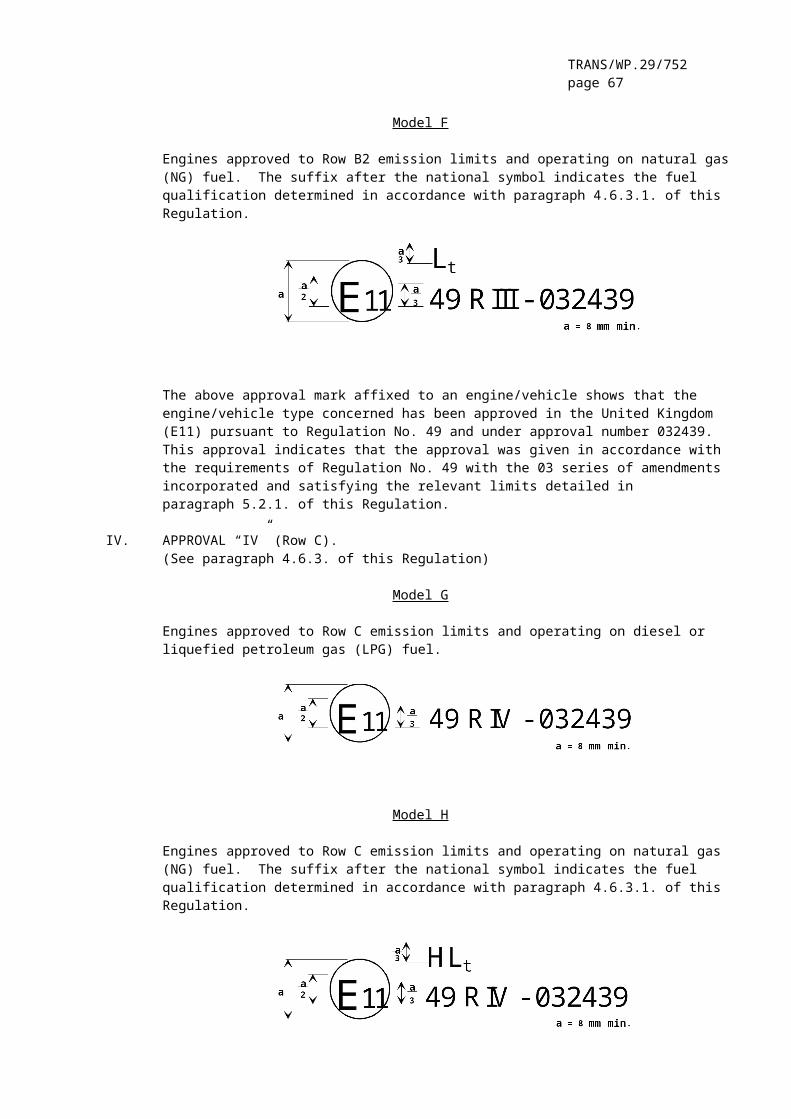
TRANS/WP.29/752page 67
The weighting factors (WF) used in the above calculation are according to paragraph 2.7.1.
4.6. Calculation of the area control values
For the three control points selected according to paragraph 2.7.6., the NOx emission must be measured and calculated according to paragraph 4.6.1. and also determined by interpolation from the modes of the test cycle closest to the respective control point according to paragraph 4.6.2. The measured values are then compared to the interpolated values according to paragraph 4.6.3.
4.6.1. Calculation of the specific emission
The NOx emission for each of the control points (Z) must be calculated as follows:
NOx mass,Z = 0.001587 * NOx conc,Z * KH,D * GEXHW
NOx,Z = NOx mass,Z / P(n)Z
4.6.2. Determination of the emission value from the test cycle
The NOx emission for each of the control points must be interpolated from the four closest modes of the test cycle that envelop the selected control point Z as shown in Figure 4. For these modes (R, S, T, U), the following definitions apply:
Speed(R) = Speed(T) = nRT
Speed(S) = Speed(U) = nSU
Per cent load(R) = Per cent load(S)Per cent load(T) = Per cent load(U).
The NOx emission of the selected control point Z must be calculated as follows:
EZ = ERS + (ETU - ERS) · (MZ - MRS) / (MTU - MRS)
and:
ETU = ET + (EU - ET) · (nZ - nRT) / (nSU - nRT)ERS = ER + (ES - ER) · (nZ - nRT) / (nSU - nRT)MTU = MT + (MU - MT) · (nZ - nRT) / (nSU - nRT)MRS = MR + (MS - MR) · (nZ - nRT) / (nSU - nRT)
where:
ER, ES, ET, EU = specific NOx emission of the enveloping modes calculated in accordance with paragraph 4.6.1.
MR, MS, MT, MU = engine torque of the enveloping modes

TRANS/WP.29/752page 68
Figure 4: Interpolation of NOx Control Point
4.6.3. Comparison of NOx emission values
The measured specific NOx emission of the control point Z (NOx,Z) is compared to the interpolated value (EZ) as follows:
NOx,diff = 100 * (NOx,z - Ez) / Ez
5. CALCULATION OF THE PARTICULATE EMISSION
5.1. Data evaluation
For the evaluation of the particulates, the total sample masses (MSAM,i) through the filters must be recorded for each mode.
The filters must be returned to the weighing chamber and conditioned for at least one hour, but not more than 80 hours, and then weighed. The gross weight of the filters must be recorded and the tare weight (see paragraph 1 of this appendix) subtracted. The particulate mass Mf is the sum of the particulate masses collected on the primary and back-up filters.
If background correction is to be applied, the dilution air mass (MDIL) through the filters and the particulate mass (Md) must be recorded. If more than one measurement was made, the quotient Md/MDIL must be calculated for each single measurement and the values averaged.
5.2. Partial flow dilution system
The final reported test results of the particulate emission must be determined through the following steps. Since various types of dilution rate control may be used, different calculation methods for
TRANS/WP.29/752page 69
GEDFW apply. All calculations must be based upon the average values of the individual modes during the sampling period.
5.2.1. Isokinetic systems
GEDFW,i = GEXHW,i * qI
where r corresponds to the ratio of the cross sectional areas of the isokinetic probe and the exhaust pipe:
5.2.2. Systems with measurement of CO2 or NOx concentration
G G qEDFW i EXHW i i, , *
where:
concE = wet concentration of the tracer gas in the raw exhaustconcD = wet concentration of the tracer gas in the diluted exhaustconcA = wet concentration of the tracer gas in the dilution air
Concentrations measured on a dry basis must be converted to a wet basis according to paragraph 4.2.of this appendix.
5.2.3. Systems with CO2 measurement and carbon balance method 1
where:
CO2D = CO2 concentration of the diluted exhaustCO2A = CO2 concentration of the dilution air (concentrations in Vol % on wet basis)
This equation is based upon the carbon balance assumption (carbon atoms supplied to the engine are emitted as CO2) and determined through the following steps:
G G qEDFW i EXHW i i, , *
1 The value is only valid for the reference fuel specified in the Regulation.
TRANS/WP.29/752page 70
and,
5.2.4. Systems with flow measurement
G G qEDFW i EXHW i i, , *
5.3. Full flow dilution system
The reported test results of the particulate emission must be determined through the following steps. All calculations must be based upon the average values of the individual modes during the sampling period.
GEDFW,i = GTOTW,i
5.4. Calculation of the particulate mass flow rate
The particulate mass flow rate must be calculated as follows:
where
i=1,...n
determined over the test cycle by summation of the average values of the individual modes during the sampling period.

TRANS/WP.29/752page 71
The particulate mass flow rate may be background corrected as follows:
If more than one measurement is made, (Md/MDIL) must be replaced with the average value of (Md/MDIL).
DFi = 13.4/(conc CO2 + (conc CO + conc HC)*10-4)) for the individual modes
or,
DFi = 13.4/concCO2 for the individual modes
5.5. Calculation of the specific emission
The particulate emission must be calculated in the following way:
5.6. Effective weighting factorThe effective weighting factor WFE,i for each mode must be calculated in the following way:
The value of the effective weighting factors must be within ± 0.003 (0.005 for the idle mode) of the weighting factors listed in paragraph 2.7.1.
6. CALCULATION OF THE SMOKE VALUES
6.1. Bessel algorithm
The Bessel algorithm must be used to compute the 1 s average values from the instantaneous smoke readings, converted in accordance with paragraph 6.3.1. The algorithm emulates a low pass second order filter, and its use requires iterative calculations to determine the coefficients. These coefficients are a function of the response time of the opacimeter system and the sampling rate. Therefore, paragraph 6.1.1. must be repeated whenever the system response time and/or sampling rate changes.

TRANS/WP.29/752page 72
6.1.1. Calculation of filter response time and Bessel constants
The required Bessel response time (tF) is a function of the physical and electrical response times of the opacimeter system, as specified in annex 4, appendix 4, paragraph 5.2.4., and must be calculated by the following equation:
where:
tp = physical response time, ste = electrical response time, s
The calculations for estimating the filter cut-off frequency (fc) are based on a step input of 0 to 1 in ≤ 0.01s (see annex 8). The response time is defined as the time between when the Bessel output reaches 10 per cent (t10) and when it reaches 90 per cent (t90) of this step function. This must be obtained by iterating on fc until t90 - t10 tF. The first iteration for fc is given by the following formula :
fc = π / (10 * tF)
The Bessel constants E and K must be calculated by the following equations:
K = 2 * E * (D * Ω2 - 1) - 1
where:
D = 0.618034Δt = 1 / sampling rateΩ = 1 / [tan(π * Δt * fc )]
6.1.2. Calculation of the Bessel Algorithm
Using the values of E and K, the 1 s Bessel averaged response to a step input Si must be calculated as follows:
Yi = Yi-1 + E * (Si + 2 * Si-1 + Si-2 - 4 * Yi-2) + K * (Yi-1 - Yi-2)
where:
Si-2 = Si-1 = 0Si = 1Yi-2 = Yi-1 = 0

TRANS/WP.29/752page 73
The times t10 and t90 must be interpolated. The difference in time between t90 and t10 defines the response time tF for that value of fc. If this response time is not close enough to the required response time, iteration must be continued until the actual response time is within 1 per cent of the required response as follows:
6.2 Data evaluation
The smoke measurement values must be sampled with a minimum rate of 20 Hz.
6.3 Determination of smoke
6.3.1 Data conversion
Since the basic measurement unit of all opacimeters is transmittance, the smoke values must be converted from transmittance (τ) to the light absorption coefficient (k) as follows:
and: N = 100 - τ
where:
k = light absorption coefficient, m-1
LA = effective optical path length, as submitted by instrument manufacturer, m
N = opacity, %τ = transmittance, %
The conversion must be applied, before any further data processing is made.
6.3.2 Calculation of Bessel averaged smoke
The proper cut-off frequency fc is the one that produces the required filter response time tF. Once this frequency has been determined through the iterative process of paragraph 6.1.1., the proper Bessel algorithm constants E and K must be calculated. The Bessel algorithm must then be applied to the instantaneous smoke trace (k-value), as described in paragraph 6.1.2:
Yi = Yi-1 + E * (Si + 2 * Si-1 + Si-2 - 4 * Yi-2) + K * (Yi-1 - Yi-2)
The Bessel algorithm is recursive in nature. Thus, it needs some initial input values of Si-1 and Si-2 and initial output values Yi-1 and Yi-2 to get the algorithm started. These may be assumed to be 0.
For each load step of the three speeds A, B and C, the maximum 1s value Ymax must be selected from the individual Yi values of each smoke trace.

TRANS/WP.29/752page 74

TRANS/WP.29/752page 75
6.3.3 Final result
The mean smoke values (SV) from each cycle (test speed) must be calculated as follows:
For test speed A: SVA = (Ymax1,A + Ymax2,A + Ymax3,A) / 3
For test speed B: SVB = (Ymax1,B + Ymax2,B + Ymax3,B) / 3
For test speed C: SVC = (Ymax1,C + Ymax2,C + Ymax3,C) / 3
where:
Ymax1, Ymax2, Ymax3 = highest 1 s Bessel averaged smoke value at each of the three load steps
The final value must be calculated as follows:
SV =(0.43 * SVA) + (0.56 * SVB) + (0.01 * SVC)
__________"
Annex 4 - Appendix 2, amend to read
"Annex 4 - Appendix 2
ETC TEST CYCLE
1. ENGINE MAPPING PROCEDURE
1.1. Determination of the mapping speed range
For generating the ETC on the test cell, the engine needs to be mapped prior to the test cycle for determining the speed vs. torque curve. The minimum and maximum mapping speeds are defined as follows:
Minimum mapping speed = idle speed
Maximum mapping speed = nhi * 1.02 or speed where full load torque drops off to zero, whichever is lower
1.2. Performing the engine power map
The engine must be warmed up at maximum power in order to stabilise the engine parameters according to the recommendation of the manufacturer and good engineering practice. When the engine is stabilised, the engine map must be performed as follows:
The engine must be unloaded and operated at idle speed.
The engine must be operated at full load setting of the injection pump at minimum mapping speed.

TRANS/WP.29/752page 76
The engine speed must be increased at an average rate of 8 ± 1 min-
1 /s from minimum to maximum mapping speed. Engine speed and torque points must be recorded at a sample rate of a least one point per second.
1.3. Mapping curve generation
All data points recorded under paragraph 1.2. must be connected using linear interpolation between points. The resulting torque curve is the mapping curve and must be used to convert the normalised torque values of the engine cycle into actual torque values for the test cycle, as described in paragraph 2.
1.4. Alternate mapping
If a manufacturer believes that the above mapping techniques are unsafe or unrepresentative for any given engine, alternate mapping techniques may be used. These alternate techniques must satisfy the intent of the specified mapping procedures to determine the maximum available torque at all engine speeds achieved during the test cycles. Deviations from the mapping techniques specified in this paragraph for reasons of safety or representativeness must be approved by the Technical Service along with the justification for their use. In no case, however, must descending continual sweeps of engine speed be used for governed or turbocharged engines.
1.5. Replicate tests
An engine need not be mapped before each and every test cycle. An engine must be remapped prior to a test cycle if:
– an unreasonable amount of time has transpired since the last map, as determined by engineering judgement,
or,
– physical changes or recalibrations have been made to the engine, which may potentially affect engine performance.
2. GENERATION OF THE REFERENCE TEST CYCLE
The transient test cycle is described in appendix 3 to this annex. The normalised values for torque and speed must be changed to the actual values, as follows, resulting in the reference cycle.
2.1. Actual speed
The speed must be unnormalised using the following equation:
Actual speed = % speed (reference speed - idle speed) + idle speed100
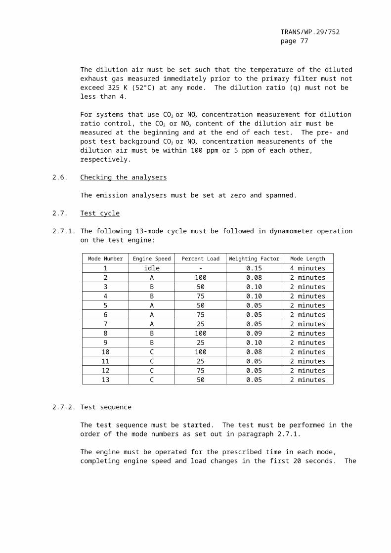
TRANS/WP.29/752page 77
The reference speed (nref) corresponds to the 100 per cent speed values specified in the engine dynamometer schedule of appendix 3. It is defined as follows (see Figure 1 of the Regulation):
nref = nlo + 95 % * (nhi - nlo)
where nhi and nlo are either specified according to the Regulation, paragraph 2 or determined according to annex 4, appendix 1, paragraph 1.1.
2.2. Actual torque
The torque is normalised to the maximum torque at the respective speed. The torque values of the reference cycle must be unnormalised, using the mapping curve determined according to section 1.3, as follows:
for the respective actual speed as determined in paragraph 2.1.
The negative torque values of the motoring points ("m") must take on, for purposes of reference cycle generation, unnormalised values determined in either of the following ways:
– negative 40 per cent of the positive torque available at the associated speed point;
– mapping of the negative torque required to motor the engine from minimum to maximum mapping speed;
– determination of the negative torque required to motor the engine at idle and reference speeds and linear interpolation between these two points.
2.3. Example of the unnormalisation procedure
As an example, the following test point must be unnormalised:
% speed = 43% torque = 82
Given the following values:
reference speed = 2200 min-1
idle speed = 600 min-1
results in,
actual speed =

TRANS/WP.29/752page 78
actual torque =
where the maximum torque observed from the mapping curve at 1288 min-1
is 700 Nm.
3. EMISSIONS TEST RUN
At the manufacturers request, a dummy test may be run for conditioning of the engine and exhaust system before the measurement cycle.
NG and LPG fuelled engines must be run-in using the ETC test. The engine must be run over a minimum of two ETC cycles and until the CO emission measured over one ETC cycle does not exceed by more than 10 per cent the CO emission measured over the previous ETC cycle.
3.1. Preparation of the sampling filters (Diesel engines only)
At least one hour before the test, each filter (pair) must be placed in a closed, but unsealed petri dish and placed in a weighing chamber for stabilisation. At the end of the stabilisation period, each filter (pair) must be weighed and the tare weight must be recorded. The filter (pair) must then be stored in a closed petri dish or sealed filter holder until needed for testing. If the filter (pair) is not used within eight hours of its removal from the weighing chamber, it must be conditioned and reweighed before use.
3.2. Installation of the measuring equipment
The instrumentation and sample probes must be installed as required. The tailpipe must be connected to the full flow dilution system.
3.3. Starting the dilution system and the engine
The dilution system and the engine must be started and warmed up until all temperatures and pressures have stabilised at maximum power according to the recommendation of the manufacturer and good engineering practice.
3.4. Starting the particulate sampling system (Diesel engines only)
The particulate sampling system must be started and running on by-pass. The particulate background level of the dilution air may be determined by passing dilution air through the particulate filters. If filtered dilution air is used, one measurement may be done prior to or after the test. If the dilution air is not filtered, measurements at the beginning and at the end of the cycle, may be done, and the values averaged.
3.5. Adjustment of the full flow dilution system
The total diluted exhaust gas flow must be set to eliminate water condensation in the system, and to obtain a maximum filter face

TRANS/WP.29/752page 79
temperature of 325 K (52°C) or less (see annex 4, appendix 7, paragraph 2.3.1., DT).
3.6. Checking the analysers
The emission analysers must be set at zero and spanned. If sample bags are used, they must be evacuated.
3.7. Engine starting procedure
The stabilised engine must be started according to the manufacturer's recommended starting procedure in the owner's manual, using either a production starter motor or the dynamometer. Optionally, the test may start directly from the engine preconditioning phase without shutting the engine off, when the engine has reached the idle speed.
3.8. Test cycle
3.8.1. Test sequence
The test sequence must be started, if the engine has reached idle speed. The test must be performed according to the reference cycle as set out in paragraph 2 of this appendix. Engine speed and torque command set points must be issued at 5 Hz (10 Hz recommended) or greater. Feedback engine speed and torque must be recorded at least once every second during the test cycle, and the signals may be electronically filtered.
3.8.2. Analyser response
At the start of the engine or test sequence, if the cycle is started directly from the preconditioning,, the measuring equipment must be started, simultaneously:
– start collecting or analysing dilution air;– start collecting or analysing diluted exhaust gas;– start measuring the amount of diluted exhaust gas (CVS) and
the required temperatures and pressures;– start recording the feedback data of speed and torque of
the dynamometer.
HC and NOx must be measured continuously in the dilution tunnel with a frequency of 2 Hz. The average concentrations must be determined by integrating the analyser signals over the test cycle. The system response time must be no greater than 20 s, and must be coordinated with CVS flow fluctuations and sampling time/test cycle offsets, if necessary. CO, CO2, NMHC and CH4 must be determined by integration or by analysing the concentrations in the sample bag, collected over the cycle. The concentrations of the gaseous pollutants in the dilution air must be determined by integration or by collecting into the background bag. All other values must be recorded with a minimum of one measurement per second (1 Hz).

TRANS/WP.29/752page 80
3.8.3. Particulate sampling (Diesel engines only)
At the start of the engine or test sequence, if the cycle is started directly from the preconditioning, the particulate sampling system must be switched from by-pass to collecting particulates.
If no flow compensation is used, the sample pump(s) must be adjusted so that the flow rate through the particulate sample probe or transfer tube is maintained at a value within ± 5 per cent of the set flow rate. If flow compensation (i.e., proportional control of sample flow) is used, it must be demonstrated that the ratio of main tunnel flow to particulate sample flow does not change by more than ± 5 per cent of its set value (except for the first 10 seconds of sampling).
Note: For double dilution operation, sample flow is the net difference between the flow rate through the sample filters and the secondary dilution air flow rate.
The average temperature and pressure at the gas meter(s) or flow instrumentation inlet must be recorded. If the set flow rate cannot be maintained over the complete cycle (within ± 5 per cent) because of high particulate loading on the filter, the test must be voided. The test must be rerun using a lower flow rate and/or a larger diameter filter.
3.8.4. Engine stalling
If the engine stalls anywhere during the test cycle, the engine must be preconditioned and restarted, and the test repeated. If a malfunction occurs in any of the required test equipment during the test cycle, the test must be voided.
3.8.5. Operations after test
At the completion of the test, the measurement of the diluted exhaust gas volume, the gas flow into the collecting bags and the particulate sample pump must be stopped. For an integrating analyser system, sampling must continue until system response times have elapsed.
The concentrations of the collecting bags, if used, must be analysed as soon as possible and in any case not later than 20 minutes after the end of the test cycle.
After the emission test, a zero gas and the same span gas must be used for re-checking the analysers. The test will be considered acceptable if the difference between the pre-test and post-test results is less than 2 per cent of the span gas value.
For diesel engines only, the particulate filters must be returned to the weighing chamber no later than one hour after completion of the test and must be conditioned in a closed, but unsealed petri dish for at least one hour, but not more than 80 hours before weighing.

TRANS/WP.29/752page 81
3.9. Verification of the test run
3.9.1. Data shift
To minimise the biasing effect of the time lag between the feedback and reference cycle values, the entire engine speed and torque feedback signal sequence may be advanced or delayed in time with respect to the reference speed and torque sequence. If the feedback signals are shifted, both speed and torque must be shifted the same amount in the same direction.
3.9.2. Calculation of the cycle work
The actual cycle work Wact (kWh) must be calculated using each pair of engine feedback speed and torque values recorded. This must be done after any feedback data shift has occurred, if this option is selected. The actual cycle work Wact is used for comparison to the reference cycle work Wref and for calculating the brake specific emissions (see paragraphs 4.4. and 5.2). The same methodology must be used for integrating both reference and actual engine power. If values are to be determined between adjacent reference or adjacent measured values, linear interpolation must be used.
In integrating the reference and actual cycle work, all negative torque values must be set equal to zero and included. If integration is performed at a frequency of less than 5 Hertz, and if, during a given time segment, the torque value changes from positive to negative or negative to positive, the negative portion must be computed and set equal to zero. The positive portion must be included in the integrated value.
Wact must be between -15 % and + 5 % of Wref.
3.9.3. Validation statistics of the test cycle
Linear regressions of the feedback values on the reference values must be performed for speed, torque and power. This must be done after any feedback data shift has occurred, if this option is selected. The method of least squares must be used, with the best fit equation having the form:
y = mx + bwhere:
y = feedback (actual) value of speed (min-1), torque (Nm),or power (kW)
m = slope of the regression linex = reference value of speed (min-1) , torque (Nm), or power (kW)b = y intercept of the regression line
The standard error of estimate (SE) of y on x and the coefficient of determination (r²) must be calculated for each regression line.
It is recommended that this analysis be performed at 1 Hertz. All negative reference torque values and the associated feedback values

TRANS/WP.29/752page 82
must be deleted from the calculation of cycle torque and power validation statistics. For a test to be considered valid, the criteria of table 6 must be met.
Table 6: Regression line tolerances
Speed Torque PowerStandard error of estimate (SE) of Y on X max 100 min-1
max 13 % of power map maximum engine torque
max 8% of power map maximum engine power
Slope of the regression line, m 0.95 to 1.03 0.83 - 1.03 0.89 - 1.03
Coefficient of determination, r² min 0.9700 min 0.8800 min 0.9100
Y intercept of the regression line, b ± 50 min-1
± 20 Nm or ± 2 % of max torque whichever is greater
± 4 kW or ± 2 % of max power whichever is greater
Point deletions from the regression analyses are permitted where noted in table 7.
Table 7: Permitted Point Deletions From Regression Analysis
Condition Points to be deleted
Full load and torque feedback ≠ torque reference Torque and/or power
No load, not an idle point, and torque feedback > torque reference Torque and/or power
No load/closed throttle, idle point and speed > reference idle speed Speed and/or power
4. CALCULATION OF THE GASEOUS EMISSIONS
4.1. Determination of the diluted exhaust gas flow
The total diluted exhaust gas flow over the cycle (kg/test) must be calculated from the measurement values over the cycle and the corresponding calibration data of the flow measurement device (V0 for PDP or KV for CFV, as determined in annex 4, appendix 5, paragraph 2.). The following formulae must be applied, if the temperature of the diluted exhaust is kept constant over the cycle by using a heat exchanger (± 6 K for a PDP-CVS, ± 11 K for a CFV-CVS, see annex 4, appendix 7, paragraph 2.3.).
For the PDP-CVS system
MTOTW = 1.293 * V0 * NP * (pB - p1) * 273 / (101.3 * T)
where:
MTOTW = mass of the diluted exhaust gas on wet basis over the cycle, kgV0 =volume of gas pumped per revolution under test conditions,
m³/revNP =total revolutions of pump per testpB =atmospheric pressure in the test cell, kPap1 =pressure depression below atmospheric at pump inlet, kPaT =average temperature of the diluted exhaust gas at pump inlet
over the cycle, K
TRANS/WP.29/752page 83
For the CFV-CVS system
MTOTW = 1.293 * t * Kv * pA / T 0.5
where:
MTOTW =mass of the diluted exhaust gas on wet basis over the cycle, kgt =cycle time, sKV =calibration coefficient of the critical flow venturi
for standard conditions, pA =absolute pressure at venturi inlet, kPaT =absolute temperature at venturi inlet, K
If a system with flow compensation is used (i.e. without heat exchanger), the instantaneous mass emissions must be calculated and integrated over the cycle. In this case, the instantaneous mass of the diluted exhaust gas must be calculated as follows.
For the PDP-CVS system:
MTOTW,I = 1.293 * V0 * NP,i * (pB - p1) * 273 / (101.3 . T)
where:
MTOTW,i =instantaneous mass of the diluted exhaust gas on wet basis, kgNP,i =total revolutions of pump per time interval
For the CFV-CVS system:
MTOTW,i =1.293 * Δti * KV * pA / T 0.5
where:
MTOTW,i =instantaneous mass of the diluted exhaust gas on wet basis, kgΔti =time interval, s
If the total sample mass of particulates (MSAM) and gaseous pollutants exceeds 0.5 per cent of the total CVS flow (MTOTW), the CVS flow must be corrected for MSAM or the particulate sample flow must be returned to the CVS prior to the flow measuring device (PDP or CFV).
4.2. NOx correction for humidity
As the NOx emission depends on ambient air conditions, the NOx concentration must be corrected for ambient air humidity with the factors given in the following formulae.
(a) for diesel engines:

TRANS/WP.29/752page 84
(b) for gas engines:
where:
Ha = humidity of the intake air, grams of water per kg of dry air,
in which:
Ra = relative humidity of the intake air, %pa = saturation vapour pressure of the intake air, kPapB = total barometric pressure, kPa
4.3. Calculation of the emission mass flow
4.3.1 Systems with constant mass flow
For systems with heat exchanger, the mass of the pollutants (g/test) must be determined from the following equations:
(1) NOx mass = 0.001587 * NOx conc * KH,D * MTOTW (diesel engines)
(2) NOx mass = 0.001587 * NOx conc * KH,G * MTOTW (gas engines)(3) CO mass = 0.000966 * CO conc * MTOTW
(4) HC mass = 0.000479 * HC conc * MTOTW' (diesel engines)
(5) HC mass = 0.000502 * HC conc * MTOTW' (LPG fuelled engines)
(6) NMHC mass = 0.000516 * NMHC conc * MTOTW' (NG fuelled engines)
(7) CH4 mass = 0.000552 * CH4 conc * MTOTW (NG fuelled engines)
where:
NOx conc, CO conc, HC conc, 1 NMHC conc = average background corrected concentrations over the cycle from integration (mandatory for NOx and HC) or bag measurement, ppm
MTOTW = total mass of diluted exhaust gas over the cycle as determined in paragraph 4.1., kg
KH,D = humidity correction factor for diesel engines as determined inparagraph 4.2
KH,G = humidity correction factor for gas engines as determined in
1 Based on C1 equivalent
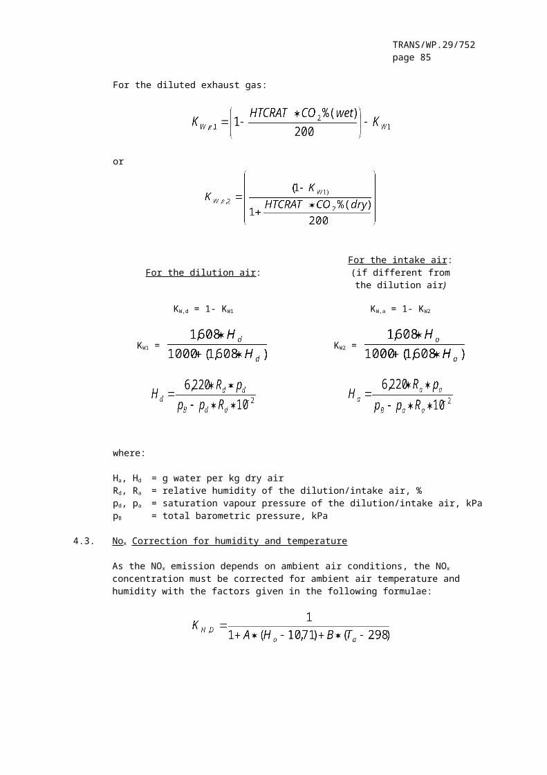
TRANS/WP.29/752page 85
paragraph 4.2
Concentrations measured on a dry basis must be converted to a wet basis in accordance with annex 4, appendix 1, paragraph 4.2.
The determination of NMHCconc depends on the method used (see annex 4, appendix 4, paragraph 3.3.4.). In both cases, the CH4 concentration must be determined and subtracted from the HC concentration as follows:
(a) GC method
NMHCconc = HCconc - CH4 conc
(b) NMC method
where:
HC(w/ Cutter) = HC concentration with the sample gas flowing through the NMC
HC(w/o Cutter) = HC concentration with the sample gas bypassing the NMC
CEM = methane efficiency as determined per annex 4, appendix 5, paragraph 1.8.4.1.
CEE = ethane efficiency as determined per annex 4, appendix 5, paragraph 1.8.4.2.
4.3.1.1. Determination of the background corrected concentrations
The average background concentration of the gaseous pollutants in the dilution air must be subtracted from measured concentrations to get the net concentrations of the pollutants. The average values of the background concentrations can be determined by the sample bag method or by continuous measurement with integration. The following formula must be used.
conc = conce - concd * (1 - (1/DF))
where:
conc = concentration of the respective pollutant in the dilutedexhaust gas, corrected by the amount of the respectivepollutant contained in the dilution air, ppm
conce = concentration of the respective pollutant measuredin the diluted exhaust gas, ppm

TRANS/WP.29/752page 86
concd = concentration of the respective pollutant measuredin the dilution air, ppm
DF = dilution factor
The dilution factor must be calculated as follows:
(a) for diesel and LPG fuelled gas engines
DF =
(b) for NG fuelled gas engines
DF = where:
CO2,conce = concentration of CO2 in the diluted exhaust gas, % volHCconce = concentration of HC in the diluted exhaust gas, ppm C1NMHCconce = concentration of NMHC in the diluted exhaust gas, ppm C1COconce = concentration of CO in the diluted exhaust gas, ppmFS = stoichiometric factor
Concentrations measured on dry basis must be converted to a wet basis in accordance with annex 4, appendix 1, paragraph 4.2.
The stoichiometric factor must be calculated as follows:
FS = where:
x,y = fuel composition CxHy
Alternatively, if the fuel composition is not known, the following stoichiometric factors may be used:
FS (diesel) = 13.4FS (LPG) = 11.6FS (NG) = 9.5
4.3.2. Systems with flow compensation
For systems without heat exchanger, the mass of the pollutants (g/test) must be determined by calculating the instantaneous mass emissions and integrating the instantaneous values over the cycle. Also, the background correction must be applied directly to the instantaneous concentration value. The following formulae must be applied:
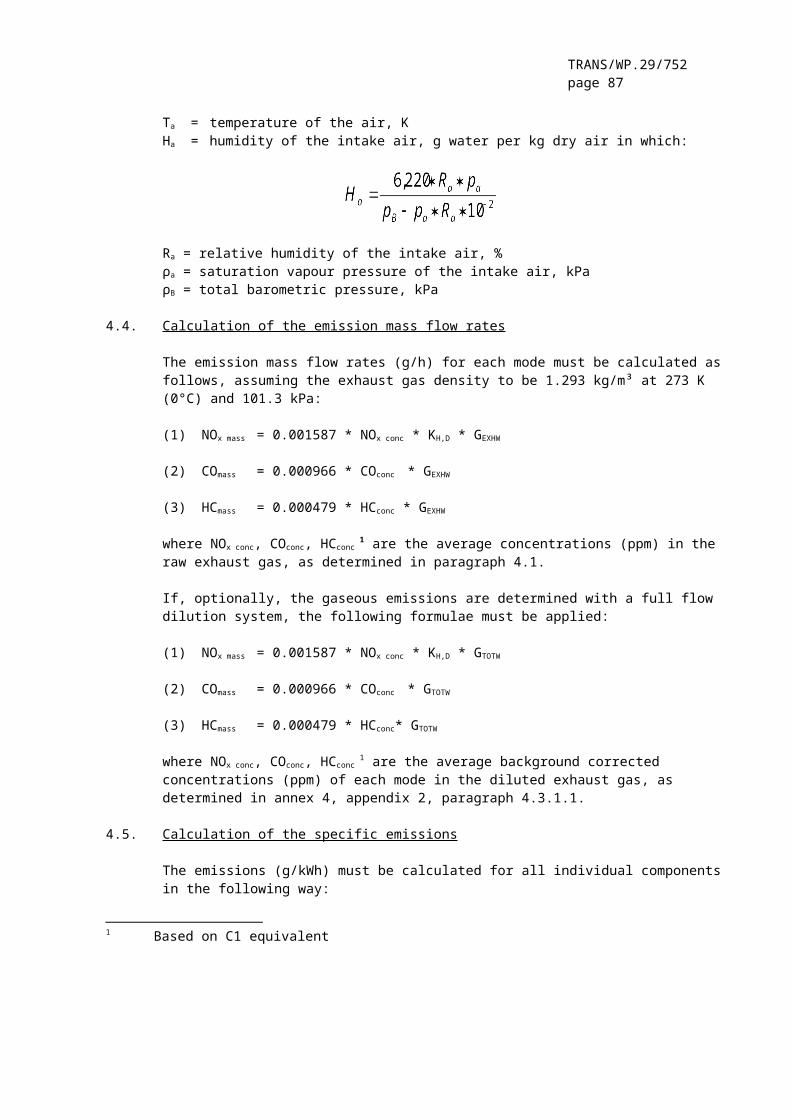
TRANS/WP.29/752page 87
(1) NOx mass =
(diesel engines)(2) NOx mass =
(gas engines)
(3) COmass =
(4) HCmass =
(diesel engines)
(5) HCmass =
(LPG engines)(6) NMHCmass =
(NG engines)(7) CH4 mass =
(NG engines)
where:
conce = concentration of the respective pollutant measured in the diluted exhaust gas, ppm
concd = concentration of the respective pollutant measured in the dilution air, ppm
MTOTW,I = instantaneous mass of the diluted exhaust gas(see paragraph 4.1.), kg
MTOTW = total mass of diluted exhaust gas over the cycle
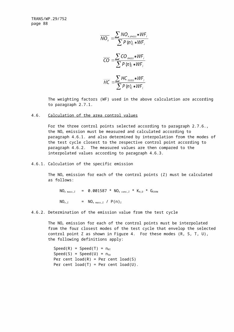
TRANS/WP.29/752page 88
(see paragraph 4.1.), kg
KH,D = humidity correction factor for diesel engines as determined in paragraph 4.2.
KH,G = humidity correction factor for gas engines as determined in paragraph 4.2
DF = dilution factor as determined in paragraph 4.3.1.1.
4.4. Calculation of the specific emissions
The emissions (g/kWh) must be calculated for all individual components in the following way:
(diesel and gas engines)
(diesel and gas engines)
(diesel and LPG fuelled gas engines)
(NG fuelled gas engines)
(NG fuelled gas engines)
where:
Wact = actual cycle work as determined in paragraph 3.9.2., kWh
5. CALCULATION OF THE PARTICULATE EMISSION (DIESEL ENGINES ONLY)
5.1. Calculation of the mass flow
The particulate mass (g/test) must be calculated as follows:
PTmass =
where:
Mf = particulate mass sampled over the cycle, mg
MTOTW = total mass of diluted exhaust gas over the cycle as determined in paragraph 4.1., kg
MSAM = mass of diluted exhaust gas taken from the dilution tunnel for collecting particulates, kg
and,
Mf = Mf,p + Mf,b, if weighed separately, mg
Mf,p = particulate mass collected on the primary filter, mg
Mf,b = particulate mass collected on the back-up filter, mg

TRANS/WP.29/752page 89
If a double dilution system is used, the mass of the secondary dilution air must be subtracted from the total mass of the double diluted exhaust gas sampled through the particulate filters.
MSAM = MTOT - MSEC
where:
MTOT = mass of double diluted exhaust gas through particulate filter, kg
MSEC = mass of secondary dilution air, kg
If the particulate background level of the dilution air is determined in accordance with paragraph 3.4., the particulate mass may be background corrected. In this case, the particulate mass (g/test) must be calculated as follows:
PTmass =
where:
Mf, MSAM, MTOTW = see aboveMDIL = mass of primary dilution air sampled by background
particulate sampler, kg Md = mass of the collected background particulates of the primary
dilution air, mgDF = dilution factor as determined in paragraph 4.3.1.1
5.2. Calculation of the specific emission
The particulate emission (g/kWh) must be calculated in the following way:
where:
Wact = actual cycle work as determined in paragraph 3.9.2., kWh.
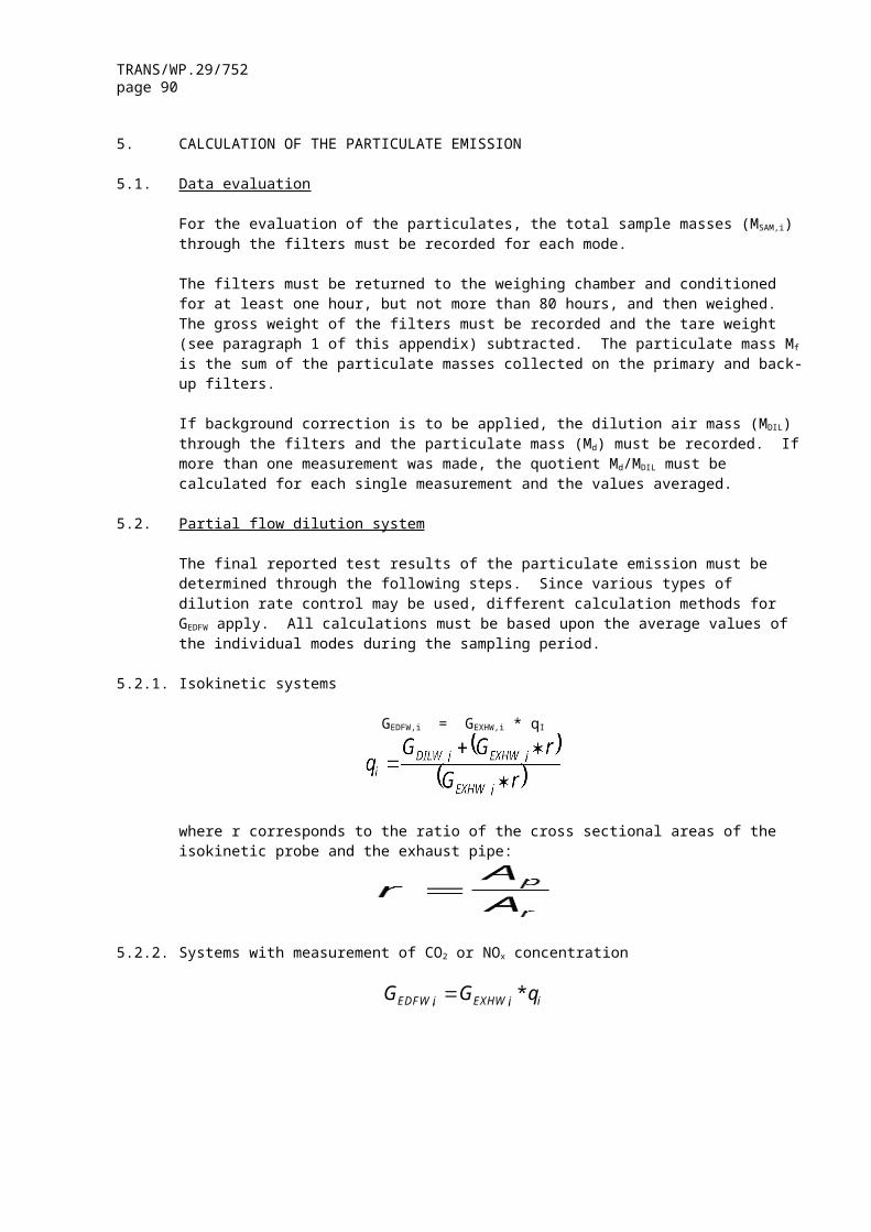
TRANS/WP.29/752page 90
ANNEX 4- APPENDIX 3
ETC ENGINE DYNAMOMETER SCHEDULE
Time Norm. Norm. Time Norm. Norm. Time Norm. Norm.Speed Torque Speed Torque Speed Torque
s % % s % % s % %1 0 0 52 0 0 103 0 02 0 0 53 0 0 104 0 03 0 0 54 0 0 105 0 04 0 0 55 0 0 106 0 05 0 0 56 0 0 107 0 06 0 0 57 0 0 108 11.6 14.87 0 0 58 0 0 109 0 08 0 0 59 0 0 110 27.2 74.89 0 0 60 0 0 111 17 76.910 0 0 61 0 0 112 36 7811 0 0 62 25.5 11.1 113 59.7 8612 0 0 63 28.5 20.9 114 80.8 17.913 0 0 64 32 73.9 115 49.7 014 0 0 65 4 82.3 116 65.6 8615 0 0 66 34.5 80.4 117 78.6 72.216 0.1 1.5 67 64.1 86 118 64.9 "m"17 23.1 21.5 68 58 0 119 44.3 "m"18 12.6 28.5 69 50.3 83.4 120 51.4 83.419 21.8 71 70 66.4 99.1 121 58.1 9720 19.7 76.8 71 81.4 99.6 122 69.3 99.321 54.6 80.9 72 88.7 73.4 123 72 20.822 71.3 4.9 73 52.5 0 124 72.1 "m"23 55.9 18.1 74 46.4 58.5 125 65.3 "m"24 72 85.4 75 48.6 90.9 126 64 "m"25 86.7 61.8 76 55.2 99.4 127 59.7 "m"26 51.7 0 77 62.3 99 128 52.8 "m"27 53.4 48.9 78 68.4 91.5 129 45.9 "m"28 34.2 87.6 79 74.5 73.7 130 38.7 "m"29 45.5 92.7 80 38 0 131 32.4 "m"30 54.6 99.5 81 41.8 89.6 132 27 "m"31 64.5 96.8 82 47.1 99.2 133 21.7 "m"32 71.7 85.4 83 52.5 99.8 134 19.1 0.433 79.4 54.8 84 56.9 80.8 135 34.7 1434 89.7 99.4 85 58.3 11.8 136 16.4 48.635 57.4 0 86 56.2 "m" 137 0 11.236 59.7 30.6 87 52 "m" 138 1.2 2.137 90.1 "m" 88 43.3 "m" 139 30.1 19.338 82.9 "m" 89 36.1 "m" 140 30 73.939 51.3 "m" 90 27.6 "m" 141 54.4 74.440 28.5 "m" 91 21.1 "m" 142 77.2 55.641 29.3 "m" 92 8 0 143 58.1 042 26.7 "m" 93 0 0 144 45 82.143 20.4 "m" 94 0 0 145 68.7 98.144 14.1 0 95 0 0 146 85.7 67.245 6.5 0 96 0 0 147 60.2 046 0 0 97 0 0 148 59.4 9847 0 0 98 0 0 149 72.7 99.648 0 0 99 0 0 150 79.9 4549 0 0 100 0 0 151 44.3 050 0 0 101 0 0 152 41.5 84.451 0 0 102 0 0 153 56.2 98.2

TRANS/WP.29/752page 91
Time Norm. Norm. Time Norm. Norm. Time Norm. Norm.Speed Torque Speed Torque Speed Torque
s % % s % % s % %154 65.7 99.1 205 0 0 256 51.7 17155 74.4 84.7 206 0 0 257 56.2 78.7156 54.4 0 207 0 0 258 59.5 94.7157 47.9 89.7 208 0 0 259 65.5 99.1158 54.5 99.5 209 0 0 260 71.2 99.5159 62.7 96.8 210 0 0 261 76.6 99.9160 62.3 0 211 0 0 262 79 0161 46.2 54.2 212 0 0 263 52.9 97.5162 44.3 83.2 213 0 0 264 53.1 99.7163 48.2 13.3 214 0 0 265 59 99.1164 51 "m" 215 0 0 266 62.2 99165 50 "m" 216 0 0 267 65 99.1166 49.2 "m" 217 0 0 268 69 83.1167 49.3 "m" 218 0 0 269 69.9 28.4168 49.9 "m" 219 0 0 270 70.6 12.5169 51.6 "m" 220 0 0 271 68.9 8.4170 49.7 "m" 221 0 0 272 69.8 9.1171 48.5 "m" 222 0 0 273 69.6 7172 50.3 72.5 223 0 0 274 65.7 "m"173 51.1 84.5 224 0 0 275 67.1 "m"174 54.6 64.8 225 21.2 62.7 276 66.7 "m"175 56.6 76.5 226 30.8 75.1 277 65.6 "m"176 58 "m" 227 5.9 82.7 278 64.5 "m"177 53.6 "m" 228 34.6 80.3 279 62.9 "m"178 40.8 "m" 229 59.9 87 280 59.3 "m"179 32.9 "m" 230 84.3 86.2 281 54.1 "m"180 26.3 "m" 231 68.7 "m" 282 51.3 "m"181 20.9 "m" 232 43.6 "m" 283 47.9 "m"182 10 0 233 41.5 85.4 284 43.6 "m"183 0 0 234 49.9 94.3 285 39.4 "m"184 0 0 235 60.8 99 286 34.7 "m"185 0 0 236 70.2 99.4 287 29.8 "m"186 0 0 237 81.1 92.4 288 20.9 73.4187 0 0 238 49.2 0 289 36.9 "m"188 0 0 239 56 86.2 290 35.5 "m"189 0 0 240 56.2 99.3 291 20.9 "m"190 0 0 241 61.7 99 292 49.7 11.9191 0 0 242 69.2 99.3 293 42.5 "m"192 0 0 243 74.1 99.8 294 32 "m"193 0 0 244 72.4 8.4 295 23.6 "m"194 0 0 245 71.3 0 296 19.1 0195 0 0 246 71.2 9.1 297 15.7 73.5196 0 0 247 67.1 "m" 298 25.1 76.8197 0 0 248 65.5 "m" 299 34.5 81.4198 0 0 249 64.4 "m" 300 44.1 87.4199 0 0 250 62.9 25.6 301 52.8 98.6200 0 0 251 62.2 35.6 302 63.6 99201 0 0 252 62.9 24.4 303 73.6 99.7202 0 0 253 58.8 "m" 304 62.2 "m"203 0 0 254 56.9 "m" 305 29.2 "m"204 0 0 255 54.5 "m" 306 46.4 22
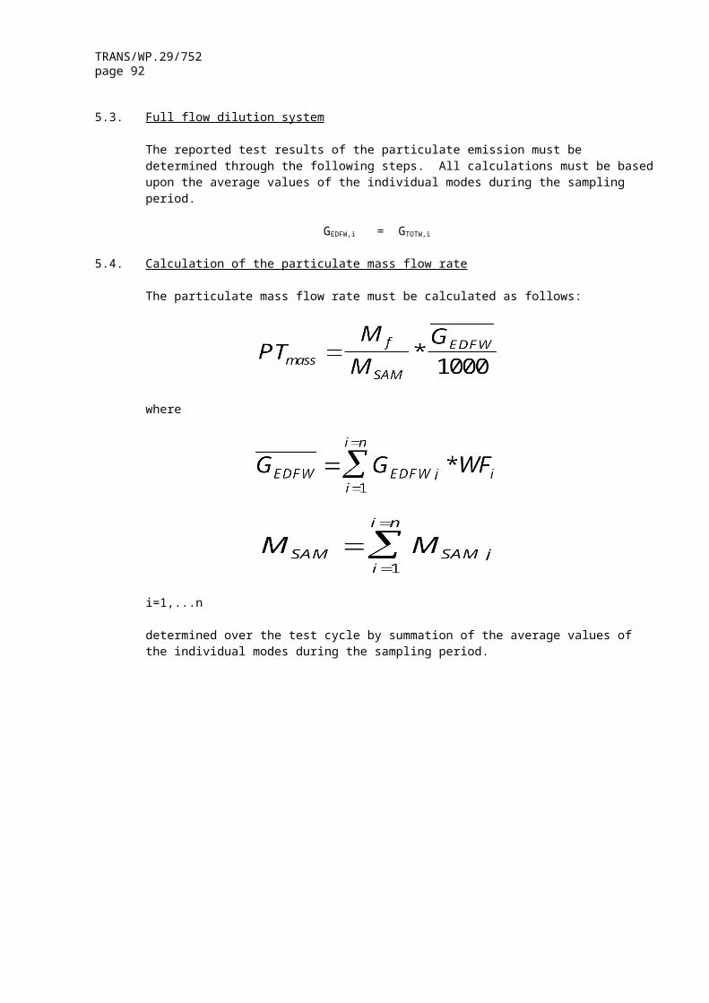
TRANS/WP.29/752page 92
Time Norm. Norm. Time Norm. Norm. Time Norm. Norm.Speed Torque Speed Torque Speed Torque
s % % s % % s % %307 47.3 13.8 358 72.6 99.6 409 56.3 72.3308 47.2 12.5 359 82.4 99.5 410 59.7 99.1309 47.9 11.5 360 88 99.4 411 62.3 99310 47.8 35.5 361 46.4 0 412 67.9 99.2311 49.2 83.3 362 53.4 95.2 413 69.5 99.3312 52.7 96.4 363 58.4 99.2 414 73.1 99.7313 57.4 99.2 364 61.5 99 415 77.7 99.8314 61.8 99 365 64.8 99 416 79.7 99.7315 66.4 60.9 366 68.1 99.2 417 82.5 99.5316 65.8 "m" 367 73.4 99.7 418 85.3 99.4317 59 "m" 368 73.3 29.8 419 86.6 99.4318 50.7 "m" 369 73.5 14.6 420 89.4 99.4319 41.8 "m" 370 68.3 0 421 62.2 0320 34.7 "m" 371 45.4 49.9 422 52.7 96.4321 28.7 "m" 372 47.2 75.7 423 50.2 99.8322 25.2 "m" 373 44.5 9 424 49.3 99.6323 43 24.8 374 47.8 10.3 425 52.2 99.8324 38.7 0 375 46.8 15.9 426 51.3 100325 48.1 31.9 376 46.9 12.7 427 51.3 100326 40.3 61 377 46.8 8.9 428 51.1 100327 42.4 52.1 378 46.1 6.2 429 51.1 100328 46.4 47.7 379 46.1 "m" 430 51.8 99.9329 46.9 30.7 380 45.5 "m" 431 51.3 100330 46.1 23.1 381 44.7 "m" 432 51.1 100331 45.7 23.2 382 43.8 "m" 433 51.3 100332 45.5 31.9 383 41 "m" 434 52.3 99.8333 46.4 73.6 384 41.1 6.4 435 52.9 99.7334 51.3 60.7 385 38 6.3 436 53.8 99.6335 51.3 51.1 386 35.9 0.3 437 51.7 99.9336 53.2 46.8 387 33.5 0 438 53.5 99.6337 53.9 50 388 53.1 48.9 439 52 99.8338 53.4 52.1 389 48.3 "m" 440 51.7 99.9339 53.8 45.7 390 49.9 "m" 441 53.2 99.7340 50.6 22.1 391 48 "m" 442 54.2 99.5341 47.8 26 392 45.3 "m" 443 55.2 99.4342 41.6 17.8 393 41.6 3.1 444 53.8 99.6343 38.7 29.8 394 44.3 79 445 53.1 99.7344 35.9 71.6 395 44.3 89.5 446 55 99.4345 34.6 47.3 396 43.4 98.8 447 57 99.2346 34.8 80.3 397 44.3 98.9 448 61.5 99347 35.9 87.2 398 43 98.8 449 59.4 5.7348 38.8 90.8 399 42.2 98.8 450 59 0349 41.5 94.7 400 42.7 98.8 451 57.3 59.8350 47.1 99.2 401 45 99 452 64.1 99351 53.1 99.7 402 43.6 98.9 453 70.9 90.5352 46.4 0 403 42.2 98.8 454 58 0353 42.5 0.7 404 44.8 99 455 41.5 59.8354 43.6 58.6 405 43.4 98.8 456 44.1 92.6355 47.1 87.5 406 45 99 457 46.8 99.2356 54.1 99.5 407 42.2 54.3 458 47.2 99.3357 62.9 99 408 61.2 31.9 459 51 100
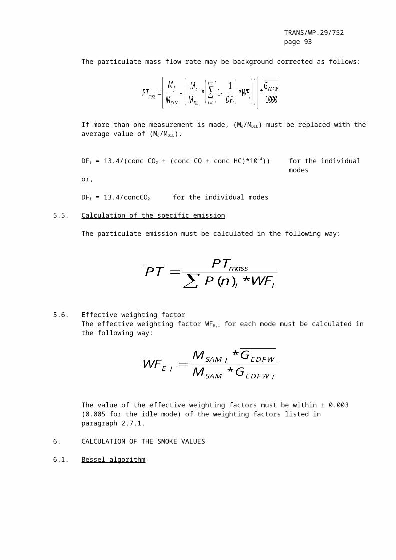
TRANS/WP.29/752page 93
Time Norm. Norm. Time Norm. Norm. Time Norm. Norm.Speed Torque Speed Torque Speed Torque
s % % s % % s % %460 53.2 99.7 511 0 0 562 58.7 "m"461 53.1 99.7 512 0 0 563 56 "m"462 55.9 53.1 513 0 0 564 53.9 "m"463 53.9 13.9 514 30.5 25.6 565 52.1 "m"464 52.5 "m" 515 19.7 56.9 566 49.9 "m"465 51.7 "m" 516 16.3 45.1 567 46.4 "m"466 51.5 52.2 517 27.2 4.6 568 43.6 "m"467 52.8 80 518 21.7 1.3 569 40.8 "m"468 54.9 95 519 29.7 28.6 570 37.5 "m"469 57.3 99.2 520 36.6 73.7 571 27.8 "m"470 60.7 99.1 521 61.3 59.5 572 17.1 0.6471 62.4 "m" 522 40.8 0 573 12.2 0.9472 60.1 "m" 523 36.6 27.8 574 11.5 1.1473 53.2 "m" 524 39.4 80.4 575 8.7 0.5474 44 "m" 525 51.3 88.9 576 8 0.9475 35.2 "m" 526 58.5 11.1 577 5.3 0.2476 30.5 "m" 527 60.7 "m" 578 4 0477 26.5 "m" 528 54.5 "m" 579 3.9 0478 22.5 "m" 529 51.3 "m" 580 0 0479 20.4 "m" 530 45.5 "m" 581 0 0480 19.1 "m" 531 40.8 "m" 582 0 0481 19.1 "m" 532 38.9 "m" 583 0 0482 13.4 "m" 533 36.6 "m" 584 0 0483 6.7 "m" 534 36.1 72.7 585 0 0484 3.2 "m" 535 44.8 78.9 586 0 0485 14.3 63.8 536 51.6 91.1 587 8.7 22.8486 34.1 0 537 59.1 99.1 588 16.2 49.4487 23.9 75.7 538 66 99.1 589 23.6 56488 31.7 79.2 539 75.1 99.9 590 21.1 56.1489 32.1 19.4 540 81 8 591 23.6 56490 35.9 5.8 541 39.1 0 592 46.2 68.8491 36.6 0.8 542 53.8 89.7 593 68.4 61.2492 38.7 "m" 543 59.7 99.1 594 58.7 "m"493 38.4 "m" 544 64.8 99 595 31.6 "m"494 39.4 "m" 545 70.6 96.1 596 19.9 8.8495 39.7 "m" 546 72.6 19.6 597 32.9 70.2496 40.5 "m" 547 72 6.3 598 43 79497 40.8 "m" 548 68.9 0.1 599 57.4 98.9498 39.7 "m" 549 67.7 "m" 600 72.1 73.8499 39.2 "m" 550 66.8 "m" 601 53 0500 38.7 "m" 551 64.3 16.9 602 48.1 86501 32.7 "m" 552 64.9 7 603 56.2 99502 30.1 "m" 553 63.6 12.5 604 65.4 98.9503 21.9 "m" 554 63 7.7 605 72.9 99.7504 12.8 0 555 64.4 38.2 606 67.5 "m"505 0 0 556 63 11.8 607 39 "m"506 0 0 557 63.6 0 608 41.9 38.1507 0 0 558 63.3 5 609 44.1 80.4508 0 0 559 60.1 9.1 610 46.8 99.4509 0 0 560 61 8.4 611 48.7 99.9510 0 0 561 59.7 0.9 612 50.5 99.7

TRANS/WP.29/752page 94
Time Norm. Norm. Time Norm. Norm. Time Norm. Norm.Speed Torque Speed Torque Speed Torque
s % % s % % s % %613 52.5 90.3 664 54 39.3 715 46.2 "m"614 51 1.8 665 53.8 "m" 716 45.6 9.8615 50 "m" 666 52 "m" 717 45.6 34.5616 49.1 "m" 667 50.4 "m" 718 45.5 37.1617 47 "m" 668 50.6 0 719 43.8 "m"618 43.1 "m" 669 49.3 41.7 720 41.9 "m"619 39.2 "m" 670 50 73.2 721 41.3 "m"620 40.6 0.5 671 50.4 99.7 722 41.4 "m"621 41.8 53.4 672 51.9 99.5 723 41.2 "m"622 44.4 65.1 673 53.6 99.3 724 41.8 "m"623 48.1 67.8 674 54.6 99.1 725 41.8 "m"624 53.8 99.2 675 56 99 726 43.2 17.4625 58.6 98.9 676 55.8 99 727 45 29626 63.6 98.8 677 58.4 98.9 728 44.2 "m"627 68.5 99.2 678 59.9 98.8 729 43.9 "m"628 72.2 89.4 679 60.9 98.8 730 38 10.7629 77.1 0 680 63 98.8 731 56.8 "m"630 57.8 79.1 681 64.3 98.9 732 57.1 "m"631 60.3 98.8 682 64.8 64 733 52 "m"632 61.9 98.8 683 65.9 46.5 734 44.4 "m"633 63.8 98.8 684 66.2 28.7 735 40.2 "m"634 64.7 98.9 685 65.2 1.8 736 39.2 16.5635 65.4 46.5 686 65 6.8 737 38.9 73.2636 65.7 44.5 687 63.6 53.6 738 39.9 89.8637 65.6 3.5 688 62.4 82.5 739 42.3 98.6638 49.1 0 689 61.8 98.8 740 43.7 98.8639 50.4 73.1 690 59.8 98.8 741 45.5 99.1640 50.5 "m" 691 59.2 98.8 742 45.6 99.2641 51 "m" 692 59.7 98.8 743 48.1 99.7642 49.4 "m" 693 61.2 98.8 744 49 100643 49.2 "m" 694 62.2 49.4 745 49.8 99.9644 48.6 "m" 695 62.8 37.2 746 49.8 99.9645 47.5 "m" 696 63.5 46.3 747 51.9 99.5646 46.5 "m" 697 64.7 72.3 748 52.3 99.4647 46 11.3 698 64.7 72.3 749 53.3 99.3648 45.6 42.8 699 65.4 77.4 750 52.9 99.3649 47.1 83 700 66.1 69.3 751 54.3 99.2650 46.2 99.3 701 64.3 "m" 752 55.5 99.1651 47.9 99.7 702 64.3 "m" 753 56.7 99652 49.5 99.9 703 63 "m" 754 61.7 98.8653 50.6 99.7 704 62.2 "m" 755 64.3 47.4654 51 99.6 705 61.6 "m" 756 64.7 1.8655 53 99.3 706 62.4 "m" 757 66.2 "m"656 54.9 99.1 707 62.2 "m" 758 49.1 "m"657 55.7 99 708 61 "m" 759 52.1 46658 56 99 709 58.7 "m" 760 52.6 61659 56.1 9.3 710 55.5 "m" 761 52.9 0660 55.6 "m" 711 51.7 "m" 762 52.3 20.4661 55.4 "m" 712 49.2 "m" 763 54.2 56.7662 54.9 51.3 713 48.8 40.4 764 55.4 59.8663 54.9 59.8 714 47.9 "m" 765 56.1 49.2

TRANS/WP.29/752page 95
Time Norm. Norm. Time Norm. Norm. Time Norm. Norm.Speed Torque Speed Torque Speed Torque
s % % s % % s % %766 56.8 33.7 817 61.7 46.2 868 53 99.3767 57.2 96 818 59.8 45.1 869 54.2 99.2768 58.6 98.9 819 57.4 43.9 870 55.5 99.1769 59.5 98.8 820 54.8 42.8 871 56.7 99770 61.2 98.8 821 54.3 65.2 872 57.3 98.9771 62.1 98.8 822 52.9 62.1 873 58 98.9772 62.7 98.8 823 52.4 30.6 874 60.5 31.1773 62.8 98.8 824 50.4 "m" 875 60.2 "m"774 64 98.9 825 48.6 "m" 876 60.3 "m"775 63.2 46.3 826 47.9 "m" 877 60.5 6.3776 62.4 "m" 827 46.8 "m" 878 61.4 19.3777 60.3 "m" 828 46.9 9.4 879 60.3 1.2778 58.7 "m" 829 49.5 41.7 880 60.5 2.9779 57.2 "m" 830 50.5 37.8 881 61.2 34.1780 56.1 "m" 831 52.3 20.4 882 61.6 13.2781 56 9.3 832 54.1 30.7 883 61.5 16.4782 55.2 26.3 833 56.3 41.8 884 61.2 16.4783 54.8 42.8 834 58.7 26.5 885 61.3 "m"784 55.7 47.1 835 57.3 "m" 886 63.1 "m"785 56.6 52.4 836 59 "m" 887 63.2 4.8786 58 50.3 837 59.8 "m" 888 62.3 22.3787 58.6 20.6 838 60.3 "m" 889 62 38.5788 58.7 "m" 839 61.2 "m" 890 61.6 29.6789 59.3 "m" 840 61.8 "m" 891 61.6 26.6790 58.6 "m" 841 62.5 "m" 892 61.8 28.1791 60.5 9.7 842 62.4 "m" 893 62 29.6792 59.2 9.6 843 61.5 "m" 894 62 16.3793 59.9 9.6 844 63.7 "m" 895 61.1 "m"794 59.6 9.6 845 61.9 "m" 896 61.2 "m"795 59.9 6.2 846 61.6 29.7 897 60.7 19.2796 59.9 9.6 847 60.3 "m" 898 60.7 32.5797 60.5 13.1 848 59.2 "m" 899 60.9 17.8798 60.3 20.7 849 57.3 "m" 900 60.1 19.2799 59.9 31 850 52.3 "m" 901 59.3 38.2800 60.5 42 851 49.3 "m" 902 59.9 45801 61.5 52.5 852 47.3 "m" 903 59.4 32.4802 60.9 51.4 853 46.3 38.8 904 59.2 23.5803 61.2 57.7 854 46.8 35.1 905 59.5 40.8804 62.8 98.8 855 46.6 "m" 906 58.3 "m"805 63.4 96.1 856 44.3 "m" 907 58.2 "m"806 64.6 45.4 857 43.1 "m" 908 57.6 "m"807 64.1 5 858 42.4 2.1 909 57.1 "m"808 63 3.2 859 41.8 2.4 910 57 0.6809 62.7 14.9 860 43.8 68.8 911 57 26.3810 63.5 35.8 861 44.6 89.2 912 56.5 29.2811 64.1 73.3 862 46 99.2 913 56.3 20.5812 64.3 37.4 863 46.9 99.4 914 56.1 "m"813 64.1 21 864 47.9 99.7 915 55.2 "m"814 63.7 21 865 50.2 99.8 916 54.7 17.5815 62.9 18 866 51.2 99.6 917 55.2 29.2816 62.4 32.7 867 52.3 99.4 918 55.2 29.2

TRANS/WP.29/752page 96
Time Norm. Norm. Time Norm. Norm. Time Norm. Norm.Speed Torque Speed Torque Speed Torque
s % % s % % s % %919 55.9 16 970 49.9 99.7 1021 49.4 "m"920 55.9 26.3 971 49.6 99.6 1022 48.3 "m"921 56.1 36.5 972 49.4 99.6 1023 49.4 "m"922 55.8 19 973 49 99.5 1024 48.5 "m"923 55.9 9.2 974 49.8 99.7 1025 48.7 "m"924 55.8 21.9 975 50.9 100 1026 48.7 "m"925 56.4 42.8 976 50.4 99.8 1027 49.1 "m"926 56.4 38 977 49.8 99.7 1028 49 "m"927 56.4 11 978 49.1 99.5 1029 49.8 "m"928 56.4 35.1 979 50.4 99.8 1030 48.7 "m"929 54 7.3 980 49.8 99.7 1031 48.5 "m"930 53.4 5.4 981 49.3 99.5 1032 49.3 31.3931 52.3 27.6 982 49.1 99.5 1033 49.7 45.3932 52.1 32 983 49.9 99.7 1034 48.3 44.5933 52.3 33.4 984 49.1 99.5 1035 49.8 61934 52.2 34.9 985 50.4 99.8 1036 49.4 64.3935 52.8 60.1 986 50.9 100 1037 49.8 64.4936 53.7 69.7 987 51.4 99.9 1038 50.5 65.6937 54 70.7 988 51.5 99.9 1039 50.3 64.5938 55.1 71.7 989 52.2 99.7 1040 51.2 82.9939 55.2 46 990 52.8 74.1 1041 50.5 86940 54.7 12.6 991 53.3 46 1042 50.6 89941 52.5 0 992 53.6 36.4 1043 50.4 81.4942 51.8 24.7 993 53.4 33.5 1044 49.9 49.9943 51.4 43.9 994 53.9 58.9 1045 49.1 20.1944 50.9 71.1 995 55.2 73.8 1046 47.9 24945 51.2 76.8 996 55.8 52.4 1047 48.1 36.2946 50.3 87.5 997 55.7 9.2 1048 47.5 34.5947 50.2 99.8 998 55.8 2.2 1049 46.9 30.3948 50.9 100 999 56.4 33.6 1050 47.7 53.5949 49.9 99.7 1000 55.4 "m" 1051 46.9 61.6950 50.9 100 1001 55.2 "m" 1052 46.5 73.6951 49.8 99.7 1002 55.8 26.3 1053 48 84.6952 50.4 99.8 1003 55.8 23.3 1054 47.2 87.7953 50.4 99.8 1004 56.4 50.2 1055 48.7 80954 49.7 99.7 1005 57.6 68.3 1056 48.7 50.4955 51 100 1006 58.8 90.2 1057 47.8 38.6956 50.3 99.8 1007 59.9 98.9 1058 48.8 63.1957 50.2 99.8 1008 62.3 98.8 1059 47.4 5958 49.9 99.7 1009 63.1 74.4 1060 47.3 47.4959 50.9 100 1010 63.7 49.4 1061 47.3 49.8960 50 99.7 1011 63.3 9.8 1062 46.9 23.9961 50.2 99.8 1012 48 0 1063 46.7 44.6962 50.2 99.8 1013 47.9 73.5 1064 46.8 65.2963 49.9 99.7 1014 49.9 99.7 1065 46.9 60.4964 50.4 99.8 1015 49.9 48.8 1066 46.7 61.5965 50.2 99.8 1016 49.6 2.3 1067 45.5 "m"966 50.3 99.8 1017 49.9 "m" 1068 45.5 "m"967 49.9 99.7 1018 49.3 "m" 1069 44.2 "m"968 51.1 100 1019 49.7 47.5 1070 43 "m"969 50.6 99.9 1020 49.1 "m" 1071 42.5 "m"
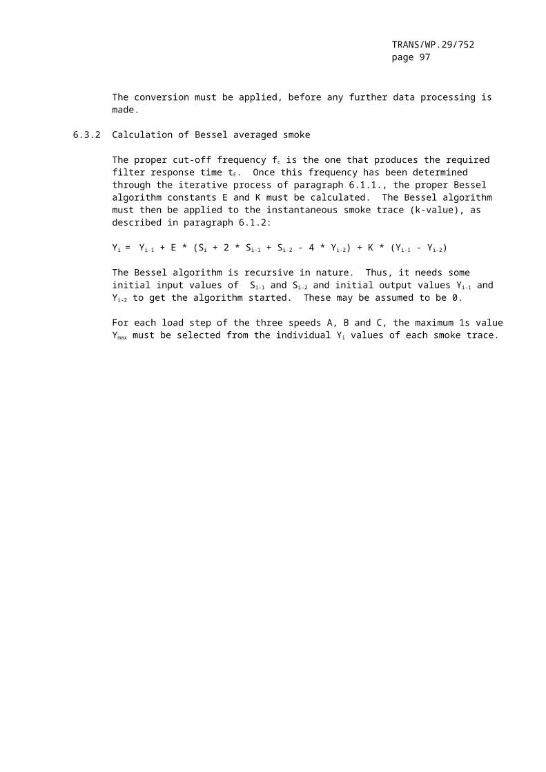
TRANS/WP.29/752page 97
Time Norm. Norm. Time Norm. Norm. Time Norm. Norm.Speed Torque Speed Torque Speed Torque
s % % s % % s % %1072 41 "m" 1123 55 "m" 1174 56.9 "m"1073 39.9 "m" 1124 53.7 "m" 1175 56.4 41074 39.9 38.2 1125 52.1 "m" 1176 57 23.41075 40.1 48.1 1126 51.1 "m" 1177 56.4 41.71076 39.9 48 1127 49.7 25.8 1178 57 49.21077 39.4 59.3 1128 49.1 46.1 1179 57.7 56.61078 43.8 19.8 1129 48.7 46.9 1180 58.6 56.61079 52.9 0 1130 48.2 46.7 1181 58.9 641080 52.8 88.9 1131 48 70 1182 59.4 68.21081 53.4 99.5 1132 48 70 1183 58.8 71.41082 54.7 99.3 1133 47.2 67.6 1184 60.1 71.31083 56.3 99.1 1134 47.3 67.6 1185 60.6 79.11084 57.5 99 1135 46.6 74.7 1186 60.7 83.31085 59 98.9 1136 47.4 13 1187 60.7 77.11086 59.8 98.9 1137 46.3 "m" 1188 60 73.51087 60.1 98.9 1138 45.4 "m" 1189 60.2 55.51088 61.8 48.3 1139 45.5 24.8 1190 59.7 54.41089 61.8 55.6 1140 44.8 73.8 1191 59.8 73.31090 61.7 59.8 1141 46.6 99 1192 59.8 77.91091 62 55.6 1142 46.3 98.9 1193 59.8 73.91092 62.3 29.6 1143 48.5 99.4 1194 60 76.51093 62 19.3 1144 49.9 99.7 1195 59.5 82.31094 61.3 7.9 1145 49.1 99.5 1196 59.9 82.81095 61.1 19.2 1146 49.1 99.5 1197 59.8 65.81096 61.2 43 1147 51 100 1198 59 48.61097 61.1 59.7 1148 51.5 99.9 1199 58.9 62.21098 61.1 98.8 1149 50.9 100 1200 59.1 70.41099 61.3 98.8 1150 51.6 99.9 1201 58.9 62.11100 61.3 26.6 1151 52.1 99.7 1202 58.4 67.41101 60.4 "m" 1152 50.9 100 1203 58.7 58.91102 58.8 "m" 1153 52.2 99.7 1204 58.3 57.71103 57.7 "m" 1154 51.5 98.3 1205 57.5 57.81104 56 "m" 1155 51.5 47.2 1206 57.2 57.61105 54.7 "m" 1156 50.8 78.4 1207 57.1 42.61106 53.3 "m" 1157 50.3 83 1208 57 70.11107 52.6 23.2 1158 50.3 31.7 1209 56.4 59.61108 53.4 84.2 1159 49.3 31.3 1210 56.7 391109 53.9 99.4 1160 48.8 21.5 1211 55.9 68.11110 54.9 99.3 1161 47.8 59.4 1212 56.3 79.11111 55.8 99.2 1162 48.1 77.1 1213 56.7 89.71112 57.1 99 1163 48.4 87.6 1214 56 89.41113 56.5 99.1 1164 49.6 87.5 1215 56 93.11114 58.9 98.9 1165 51 81.4 1216 56.4 93.11115 58.7 98.9 1166 51.6 66.7 1217 56.7 94.41116 59.8 98.9 1167 53.3 63.2 1218 56.9 94.81117 61 98.8 1168 55.2 62 1219 57 94.11118 60.7 19.2 1169 55.7 43.9 1220 57.7 94.31119 59.4 "m" 1170 56.4 30.7 1221 57.5 93.71120 57.9 "m" 1171 56.8 23.4 1222 58.4 93.21121 57.6 "m" 1172 57 "m" 1223 58.7 93.21122 56.3 "m" 1173 57.6 "m" 1224 58.2 93.7

TRANS/WP.29/752page 98
Time Norm. Norm. Time Norm. Norm. Time Norm. Norm.Speed Torque Speed Torque Speed Torque
s % % s % % s % %1225 58.5 93.1 1276 60.6 5.5 1327 63.1 20.31226 58.8 86.2 1277 61 14.3 1328 61.8 19.11227 59 72.9 1278 61 12 1329 61.6 17.11228 58.2 59.9 1279 61.3 34.2 1330 61 01229 57.6 8.5 1280 61.2 17.1 1331 61.2 221230 57.1 47.6 1281 61.5 15.7 1332 60.8 40.31231 57.2 74.4 1282 61 9.5 1333 61.1 34.31232 57 79.1 1283 61.1 9.2 1334 60.7 16.11233 56.7 67.2 1284 60.5 4.3 1335 60.6 16.61234 56.8 69.1 1285 60.2 7.8 1336 60.5 18.51235 56.9 71.3 1286 60.2 5.9 1337 60.6 29.81236 57 77.3 1287 60.2 5.3 1338 60.9 19.51237 57.4 78.2 1288 59.9 4.6 1339 60.9 22.31238 57.3 70.6 1289 59.4 21.5 1340 61.4 35.81239 57.7 64 1290 59.6 15.8 1341 61.3 42.91240 57.5 55.6 1291 59.3 10.1 1342 61.5 311241 58.6 49.6 1292 58.9 9.4 1343 61.3 19.21242 58.2 41.1 1293 58.8 9 1344 61 9.31243 58.8 40.6 1294 58.9 35.4 1345 60.8 44.21244 58.3 21.1 1295 58.9 30.7 1346 60.9 55.31245 58.7 24.9 1296 58.9 25.9 1347 61.2 561246 59.1 24.8 1297 58.7 22.9 1348 60.9 60.11247 58.6 "m" 1298 58.7 24.4 1349 60.7 59.11248 58.8 "m" 1299 59.3 61 1350 60.9 56.81249 58.8 "m" 1300 60.1 56 1351 60.7 58.11250 58.7 "m" 1301 60.5 50.6 1352 59.6 78.41251 59.1 "m" 1302 59.5 16.2 1353 59.6 84.61252 59.1 "m" 1303 59.7 50 1354 59.4 66.61253 59.4 "m" 1304 59.7 31.4 1355 59.3 75.51254 60.6 2.6 1305 60.1 43.1 1356 58.9 49.61255 59.6 "m" 1306 60.8 38.4 1357 59.1 75.81256 60.1 "m" 1307 60.9 40.2 1358 59 77.61257 60.6 "m" 1308 61.3 49.7 1359 59 67.81258 59.6 4.1 1309 61.8 45.9 1360 59 56.71259 60.7 7.1 1310 62 45.9 1361 58.8 54.21260 60.5 "m" 1311 62.2 45.8 1362 58.9 59.61261 59.7 "m" 1312 62.6 46.8 1363 58.9 60.81262 59.6 "m" 1313 62.7 44.3 1364 59.3 56.11263 59.8 "m" 1314 62.9 44.4 1365 58.9 48.51264 59.6 4.9 1315 63.1 43.7 1366 59.3 42.91265 60.1 5.9 1316 63.5 46.1 1367 59.4 41.41266 59.9 6.1 1317 63.6 40.7 1368 59.6 38.91267 59.7 "m" 1318 64.3 49.5 1369 59.4 32.91268 59.6 "m" 1319 63.7 27 1370 59.3 30.61269 59.7 22 1320 63.8 15 1371 59.4 301270 59.8 10.3 1321 63.6 18.7 1372 59.4 25.31271 59.9 10 1322 63.4 8.4 1373 58.8 18.61272 60.6 6.2 1323 63.2 8.7 1374 59.1 181273 60.5 7.3 1324 63.3 21.6 1375 58.5 10.61274 60.2 14.8 1325 62.9 19.7 1376 58.8 10.51275 60.6 8.2 1326 63 22.1 1377 58.5 8.2

TRANS/WP.29/752page 99
Time Norm. Norm. Time Norm. Norm. Time Norm. Norm.Speed Torque Speed Torque Speed Torque
s % % s % % s % %1378 58.7 13.7 1429 62.3 37.4 1480 60.1 4.71379 59.1 7.8 1430 62.3 35.7 1481 59.9 01380 59.1 6 1431 62.8 34.4 1482 60.4 36.21381 59.1 6 1432 62.8 31.5 1483 60.7 32.51382 59.4 13.1 1433 62.9 31.7 1484 59.9 3.11383 59.7 22.3 1434 62.9 29.9 1485 59.7 "m"1384 60.7 10.5 1435 62.8 29.4 1486 59.5 "m"1385 59.8 9.8 1436 62.7 28.7 1487 59.2 "m"1386 60.2 8.8 1437 61.5 14.7 1488 58.8 0.61387 59.9 8.7 1438 61.9 17.2 1489 58.7 "m"1388 61 9.1 1439 61.5 6.1 1490 58.7 "m"1389 60.6 28.2 1440 61 9.9 1491 57.9 "m"1390 60.6 22 1441 60.9 4.8 1492 58.2 "m"1391 59.6 23.2 1442 60.6 11.1 1493 57.6 "m"1392 59.6 19 1443 60.3 6.9 1494 58.3 9.51393 60.6 38.4 1444 60.8 7 1495 57.2 61394 59.8 41.6 1445 60.2 9.2 1496 57.4 27.31395 60 47.3 1446 60.5 21.7 1497 58.3 59.91396 60.5 55.4 1447 60.2 22.4 1498 58.3 7.31397 60.9 58.7 1448 60.7 31.6 1499 58.8 21.71398 61.3 37.9 1449 60.9 28.9 1500 58.8 38.91399 61.2 38.3 1450 59.6 21.7 1501 59.4 26.21400 61.4 58.7 1451 60.2 18 1502 59.1 25.51401 61.3 51.3 1452 59.5 16.7 1503 59.1 261402 61.4 71.1 1453 59.8 15.7 1504 59 39.11403 61.1 51 1454 59.6 15.7 1505 59.5 52.31404 61.5 56.6 1455 59.3 15.7 1506 59.4 311405 61 60.6 1456 59 7.5 1507 59.4 271406 61.1 75.4 1457 58.8 7.1 1508 59.4 29.81407 61.4 69.4 1458 58.7 16.5 1509 59.4 23.11408 61.6 69.9 1459 59.2 50.7 1510 58.9 161409 61.7 59.6 1460 59.7 60.2 1511 59 31.51410 61.8 54.8 1461 60.4 44 1512 58.8 25.91411 61.6 53.6 1462 60.2 35.3 1513 58.9 40.21412 61.3 53.5 1463 60.4 17.1 1514 58.8 28.41413 61.3 52.9 1464 59.9 13.5 1515 58.9 38.91414 61.2 54.1 1465 59.9 12.8 1516 59.1 35.31415 61.3 53.2 1466 59.6 14.8 1517 58.8 30.31416 61.2 52.2 1467 59.4 15.9 1518 59 191417 61.2 52.3 1468 59.4 22 1519 58.7 31418 61 48 1469 60.4 38.4 1520 57.9 01419 60.9 41.5 1470 59.5 38.8 1521 58 2.41420 61 32.2 1471 59.3 31.9 1522 57.1 "m"1421 60.7 22 1472 60.9 40.8 1523 56.7 "m"1422 60.7 23.3 1473 60.7 39 1524 56.7 5.31423 60.8 38.8 1474 60.9 30.1 1525 56.6 2.11424 61 40.7 1475 61 29.3 1526 56.8 "m"1425 61 30.6 1476 60.6 28.4 1527 56.3 "m"1426 61.3 62.6 1477 60.9 36.3 1528 56.3 "m"1427 61.7 55.9 1478 60.8 30.5 1529 56 "m"1428 62.3 43.4 1479 60.7 26.7 1530 56.7 "m"

TRANS/WP.29/752page 100
Time Norm. Norm. Time Norm. Norm. Time Norm. Norm.Speed Torque Speed Torque Speed Torque
s % % s % % s % %1531 56.6 3.8 1582 59.9 73.6 1633 62.5 311532 56.9 "m" 1583 59.8 74.1 1634 62.3 31.31533 56.9 "m" 1584 59.6 84.6 1635 62.6 31.71534 57.4 "m" 1585 59.4 76.1 1636 62.3 22.81535 57.4 "m" 1586 60.1 76.9 1637 62.7 12.61536 58.3 13.9 1587 59.5 84.6 1638 62.2 15.21537 58.5 "m" 1588 59.8 77.5 1639 61.9 32.61538 59.1 "m" 1589 60.6 67.9 1640 62.5 23.11539 59.4 "m" 1590 59.3 47.3 1641 61.7 19.41540 59.6 "m" 1591 59.3 43.1 1642 61.7 10.81541 59.5 "m" 1592 59.4 38.3 1643 61.6 10.21542 59.6 0.5 1593 58.7 38.2 1644 61.4 "m"1543 59.3 9.2 1594 58.8 39.2 1645 60.8 "m"1544 59.4 11.2 1595 59.1 67.9 1646 60.7 "m"1545 59.1 26.8 1596 59.7 60.5 1647 61 12.41546 59 11.7 1597 59.5 32.9 1648 60.4 5.31547 58.8 6.4 1598 59.6 20 1649 61 13.11548 58.7 5 1599 59.6 34.4 1650 60.7 29.61549 57.5 "m" 1600 59.4 23.9 1651 60.5 28.91550 57.4 "m" 1601 59.6 15.7 1652 60.8 27.11551 57.1 1.1 1602 59.9 41 1653 61.2 27.31552 57.1 0 1603 60.5 26.3 1654 60.9 20.61553 57 4.5 1604 59.6 14 1655 61.1 13.91554 57.1 3.7 1605 59.7 21.2 1656 60.7 13.41555 57.3 3.3 1606 60.9 19.6 1657 61.3 26.11556 57.3 16.8 1607 60.1 34.3 1658 60.9 23.71557 58.2 29.3 1608 59.9 27 1659 61.4 32.11558 58.7 12.5 1609 60.8 25.6 1660 61.7 33.51559 58.3 12.2 1610 60.6 26.3 1661 61.8 34.11560 58.6 12.7 1611 60.9 26.1 1662 61.7 171561 59 13.6 1612 61.1 38 1663 61.7 2.51562 59.8 21.9 1613 61.2 31.6 1664 61.5 5.91563 59.3 20.9 1614 61.4 30.6 1665 61.3 14.91564 59.7 19.2 1615 61.7 29.6 1666 61.5 17.21565 60.1 15.9 1616 61.5 28.8 1667 61.1 "m"1566 60.7 16.7 1617 61.7 27.8 1668 61.4 "m"1567 60.7 18.1 1618 62.2 20.3 1669 61.4 8.81568 60.7 40.6 1619 61.4 19.6 1670 61.3 8.81569 60.7 59.7 1620 61.8 19.7 1671 61 181570 61.1 66.8 1621 61.8 18.7 1672 61.5 131571 61.1 58.8 1622 61.6 17.7 1673 61 3.71572 60.8 64.7 1623 61.7 8.7 1674 60.9 3.11573 60.1 63.6 1624 61.7 1.4 1675 60.9 4.71574 60.7 83.2 1625 61.7 5.9 1676 60.6 4.11575 60.4 82.2 1626 61.2 8.1 1677 60.6 6.71576 60 80.5 1627 61.9 45.8 1678 60.6 12.81577 59.9 78.7 1628 61.4 31.5 1679 60.7 11.91578 60.8 67.9 1629 61.7 22.3 1680 60.6 12.41579 60.4 57.7 1630 62.4 21.7 1681 60.1 12.41580 60.2 60.6 1631 62.8 21.9 1682 60.5 121581 59.6 72.7 1632 62.2 22.2 1683 60.4 11.8
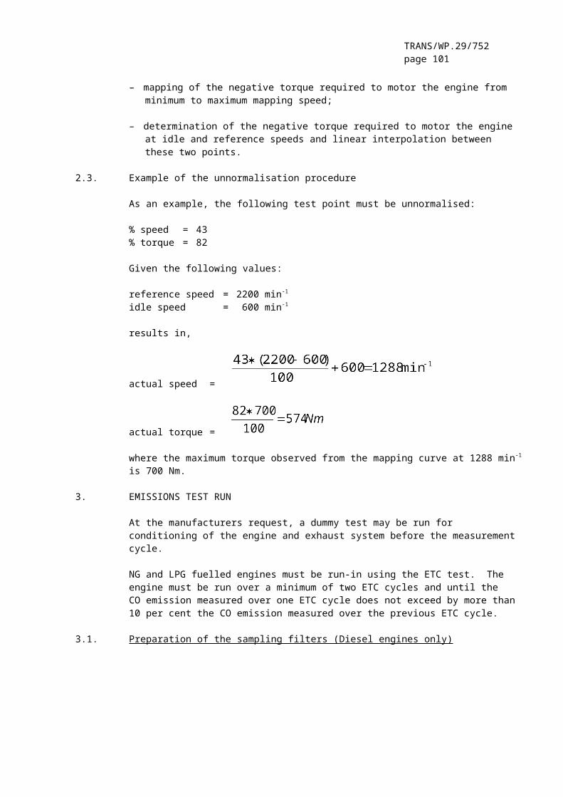
TRANS/WP.29/752page 101
Time Norm. Norm. Time Norm. Norm. Time Norm. Norm.Speed Torque Speed Torque Speed Torque
s % % s % % s % %1684 59.9 12.4 1735 61.1 25.6 1786 0 01685 59.6 12.4 1736 61 14.6 1787 0 01686 59.6 9.1 1737 61 10.4 1788 0 01687 59.9 0 1738 60.6 "m" 1789 0 01688 59.9 20.4 1739 60.9 "m" 1790 0 01689 59.8 4.4 1740 60.8 4.8 1791 0 01690 59.4 3.1 1741 59.9 "m" 1792 0 01691 59.5 26.3 1742 59.8 "m" 1793 0 01692 59.6 20.1 1743 59.1 "m" 1794 0 01693 59.4 35 1744 58.8 "m" 1795 0 01694 60.9 22.1 1745 58.8 "m" 1796 0 01695 60.5 12.2 1746 58.2 "m" 1797 0 01696 60.1 11 1747 58.5 14.3 1798 0 01697 60.1 8.2 1748 57.5 4.4 1799 0 01698 60.5 6.7 1749 57.9 0 1800 0 01699 60 5.1 1750 57.8 20.91700 60 5.1 1751 58.3 9.21701 60 9 1752 57.8 8.21702 60.1 5.7 1753 57.5 15.31703 59.9 8.5 1754 58.4 381704 59.4 6 1755 58.1 15.41705 59.5 5.5 1756 58.8 11.81706 59.5 14.2 1757 58.3 8.11707 59.5 6.2 1758 58.3 5.51708 59.4 10.3 1759 59 4.11709 59.6 13.8 1760 58.2 4.91710 59.5 13.9 1761 57.9 10.11711 60.1 18.9 1762 58.5 7.51712 59.4 13.1 1763 57.4 71713 59.8 5.4 1764 58.2 6.71714 59.9 2.9 1765 58.2 6.61715 60.1 7.1 1766 57.3 17.31716 59.6 12 1767 58 11.41717 59.6 4.9 1768 57.5 47.41718 59.4 22.7 1769 57.4 28.81719 59.6 22 1770 58.8 24.31720 60.1 17.4 1771 57.7 25.51721 60.2 16.6 1772 58.4 35.51722 59.4 28.6 1773 58.4 29.31723 60.3 22.4 1774 59 33.81724 59.9 20 1775 59 18.71725 60.2 18.6 1776 58.8 9.81726 60.3 11.9 1777 58.8 23.91727 60.4 11.6 1778 59.1 48.21728 60.6 10.6 1779 59.4 37.21729 60.8 16 1780 59.6 29.11730 60.9 17 1781 50 251731 60.9 16.1 1782 40 201732 60.7 11.4 1783 30 151733 60.9 11.3 1784 20 101734 61.1 11.2 1785 10 5
"m" = motoring
TRANS/WP.29/752page 102
A graphical display of the ETC dynamometer schedule is shown in Figure 5.
Figure 5: ETC Dynamometer Schedule
__________"
Annex 4 – Appendix 4, amend to read:
"Annex 4 - Appendix 4
MEASUREMENT AND SAMPLING PROCEDURES
1. INTRODUCTION
Gaseous components, particulates, and smoke emitted by the engine submitted for testing must be measured by the methods described in annex 4, appendix 7. The respective paragraphs of annex 4, appendix 7 describe the recommended analytical systems for the gaseous emissions (paragraph 1.), the recommended particulate dilution and sampling systems (paragraph 2.), and the recommended opacimeters for smoke measurement (paragraph 3.).
For the ESC, the gaseous components must be determined in the raw exhaust gas. Optionally, they may be determined in the diluted exhaust gas, if a full flow dilution system is used for particulate determination. Particulates must be determined with either a partial flow or a full flow dilution system.
Tor
que
[%]
S
peed
{%]

TRANS/WP.29/752page 103
For the ETC, only a full flow dilution system must be used for determining gaseous and particulate emissions, and is considered the reference system. However, partial flow dilution systems may be approved by the Technical Service, if their equivalency according to paragraph 6.2. to the Regulation is proven, and if a detailed description of the data evaluation and calculation procedures is submitted to the Technical Service.
2. DYNAMOMETER AND TEST CELL EQUIPMENT
The following equipment must be used for emission tests of engines on engine dynamometers.
2.1. Engine dynamometer
An engine dynamometer must be used with adequate characteristics to perform the test cycles described in appendices 1 and 2 to this annex. The speed measuring system must have an accuracy of ± 2 per cent of reading. The torque measuring system must have an accuracy of ± 3 per cent of reading in the range > 20 per cent of full scale, and an accuracy of ± 0.6 per cent of full scale in the range ≤ 20 per cent of full scale.
2.2. Other instruments
Measuring instruments for fuel consumption, air consumption, temperature of coolant and lubricant, exhaust gas pressure and intake manifold depression, exhaust gas temperature, air intake temperature, atmospheric pressure, humidity and fuel temperature must be used, as required. These instruments must satisfy the requirements given in table 8:
Table 8: Accuracy of measuring instruments
Measuring instrument AccuracyFuel Consumption ± 2 % of Engine's Maximum ValueAir Consumption ± 2 % of Engine's Maximum ValueTemperatures ≤ 600 K (327°C) ± 2 K AbsoluteTemperatures ≥ 600 K (327°C) ± 1 % of ReadingAtmospheric Pressure ± 0.1 kPa AbsoluteExhaust Gas Pressure ± 0.2 kPa AbsoluteIntake Depression ± 0.05 kPa AbsoluteOther Pressures ± 0.1 kPa AbsoluteRelative Humidity ± 3 % AbsoluteAbsolute Humidity ± 5 % of Reading
2.3. Exhaust gas flow
For calculation of the emissions in the raw exhaust, it is necessary to know the exhaust gas flow (see paragraph 4.4. of appendix 1). For the determination of the exhaust flow either of the following methods may be used:

TRANS/WP.29/752page 104
Direct measurement of the exhaust flow by flow nozzle or equivalent metering system;Measurement of the air flow and the fuel flow by suitable metering systems and calculation of the exhaust flow by the following equation:
GEXHW = GAIRW + GFUEL (for wet exhaust mass)
The accuracy of exhaust flow determination must be ± 2.5 per cent of reading or better.
2.4. Diluted exhaust gas flow
For calculation of the emissions in the diluted exhaust using a full flow dilution system (mandatory for the ETC), it is necessary to know the diluted exhaust gas flow (see paragraph 4.3. of appendix 2). The total mass flow rate of the diluted exhaust (GTOTW) or the total mass of the diluted exhaust gas over the cycle (MTOTW) must be measured with a PDP or CFV (annex 4, appendix 7, paragraph 2.3.1.). The accuracy must be ± 2 per cent of reading or better, and must be determined according to the provisions of annex 4, appendix 5, paragraph 2.4.
3. DETERMINATION OF THE GASEOUS COMPONENTS
3.1. General analyser specifications
The analysers must have a measuring range appropriate for the accuracy required to measure the concentrations of the exhaust gas components (paragraph 3.1.1). It is recommended that the analysers be operated such that the measured concentration falls between 15 per cent and 100 per cent of full scale.
If read-out systems (computers, data loggers) can provide sufficient accuracy and resolution below 15 per cent of full scale, measurements below 15 per cent of full scale are also acceptable. In this case, additional calibrations of at least 4 non-zero nominally equally spaced points are to be made to ensure the accuracy of the calibration curves according to annex 4, appendix 5, paragraph 1.5.5.2.
The electromagnetic compatibility (EMC) of the equipment must be on a level as to minimise additional errors.
3.1.1. Measurement error
The total measurement error, including the cross sensitivity to other gases (see annex 4, appendix 5, paragraph 1.9.), must not exceed ± 5 per cent of the reading or ± 3.5 per cent of full scale, whichever is smaller. For concentrations of less than 100 ppm the measurement error must not exceed ± 4 ppm.

TRANS/WP.29/752page 105
3.1.2. Repeatability
The repeatability, defined as 2.5 times the standard deviation of 10 repetitive responses to a given calibration or span gas, has to be not greater than ± 1 per cent of full scale concentration for each range used above 155 ppm (or ppm C) or ± 2 per cent of each range used below 155 ppm (or ppm C).
3.1.3. Noise
The analyser peak-to-peak response to zero and calibration or span gases over any 10 seconds period must not exceed 2 per cent of full scale on all ranges used.
3.1.4. Zero drift
The zero drift during a one hour period must be less than 2 per cent of full scale on the lowest range used. The zero response is defined as the mean response, including noise, to a zero gas during a 30 seconds time interval.
3.1.5 Span drift
The span drift during a one hour period must be less than 2 per cent of full scale on the lowest range used. Span is defined as the difference between the span response and the zero response. The span response is defined as the mean response, including noise, to a span gas during a 30 seconds time interval.
3.2. Gas drying
The optional gas drying device must have a minimal effect on the concentration of the measured gases. Chemical dryers are not an acceptable method of removing water from the sample.
3.3. Analysers
Paragraphs 3.3.1. to 3.3.4. describe the measurement principles to be used. A detailed description of the measurement systems is given in annex 4, appendix 7. The gases to be measured must be analysed with the following instruments. For non-linear analysers, the use of linearising circuits is permitted.
3.3.1. Carbon monoxide (CO) analysis
The carbon monoxide analyser must be of the Non-Dispersive Infra-Red (NDIR) absorption type.
3.3.2. Carbon dioxide (CO2) analysis
The carbon dioxide analyser must be of the Non-Dispersive Infra-Red (NDIR) absorption type.
TRANS/WP.29/752page 106
3.3.3. Hydrocarbon (HC) analysis
For diesel and LPG fuelled gas engines, the hydrocarbon analyser must be of the Heated Flame Ionisation Detector (HFID) type with detector, valves, pipework, etc. heated so as to maintain a gas temperature of 463K ± 10K (190 ± 10°C). For NG fuelled gas engines, the hydrocarbon analyser may be of the non heated Flame Ionisation Detector (FID) type depending upon the method used (see annex 4, appendix 7, paragraph 1.3.).
3.3.4. Non-methane hydrocarbon (NMHC) analysis (NG fuelled gas engines only)
Non-methane hydrocarbons must be determined by either of the following methods:
3.3.4.1 Gas chromatographic (GC) method
Non-methane hydrocarbons must be determined by subtraction of the methane analysed with a Gas Chromatograph (GC) conditioned at 423 K (150°C) from the hydrocarbons measured according to paragraph 3.3.3.
3.3.4.2. Non-methane cutter (NMC) method
The determination of the non-methane fraction must be performed with a heated NMC operated in line with an FID as per paragraph 3.3.3. by subtraction of the methane from the hydrocarbons.
3.3.5. Oxides of nitrogen (NOx) analysis
The oxides of nitrogen analyser must be of the Chemi-Luminescent Detector (CLD) or Heated Chemi-Luminescent Detector (HCLD) type with a NO2/NO converter, if measured on a dry basis. If measured on a wet basis, a HCLD with converter maintained above 328 K (55°C) must be used, provided the water quench check (see annex 4, appendix 5, paragraph 1.9.2.2.) is satisfied.
3.4. Sampling of gaseous emissions
3.4.1. Raw exhaust gas (ESC only)
The gaseous emissions sampling probes must be fitted at least 0.5 m or 3 times the diameter of the exhaust pipe - whichever is the larger - upstream of the exit of the exhaust gas system as far as applicable and sufficiently close to the engine as to ensure an exhaust gas temperature of at least 343 K (70°C) at the probe.
In the case of a multi-cylinder engine with a branched exhaust manifold, the inlet of the probe must be located sufficiently far downstream so as to ensure that the sample is representative of the average exhaust emissions from all cylinders. In multi-cylinder engines having distinct groups of manifolds, such as in a "Vee" engine configuration, it is permissible to acquire a sample from each group individually and calculate an average exhaust emission. Other methods which have been shown to correlate with the above methods may

TRANS/WP.29/752page 107
be used. For exhaust emission calculation the total exhaust mass flow must be used.If the engine is equipped with an exhaust after-treatment system, the exhaust sample must be taken downstream of the exhaust after-treatment system.
3.4.2. Diluted exhaust gas (mandatory for ETC, optional for ESC)
The exhaust pipe between the engine and the full flow dilution system must conform to the requirements of annex 4, appendix 7, paragraph 2.3.1., EP.
The gaseous emissions sample probe(s) must be installed in the dilution tunnel at a point where the dilution air and exhaust gas are well mixed, and in close proximity to the particulates sampling probe.
For the ETC, sampling can generally be done in two ways:
– the pollutants are sampled into a sampling bag over the cycle and measured after completion of the test;
– the pollutants are sampled continuously and integrated over the cycle; this method is mandatory for HC and NOx.
4. DETERMINATION OF THE PARTICULATES
The determination of the particulates requires a dilution system. Dilution may be accomplished by a partial flow dilution system (ESC only) or a full flow dilution system (mandatory for ETC). The flow capacity of the dilution system must be large enough to completely eliminate water condensation in the dilution and sampling systems, and maintain the temperature of the diluted exhaust gas at or below 325K (52°C) immediately upstream of the filter holders. Dehumidifying the dilution air before entering the dilution system is permitted, and especially useful if dilution air humidity is high. The temperature of the dilution air must be 298 K ± 5 K (25°C ± 5°C). If the ambient temperature is below 293K (20°C), dilution air pre-heating above the upper temperature limit of 303K (30°C) is recommended. However, the dilution air temperature must not exceed 325 K (52°C) prior to the introduction of the exhaust in the dilution tunnel.
The partial flow dilution system has to be designed to split the exhaust stream into two fractions, the smaller one being diluted with air and subsequently used for particulate measurement. For this it is essential that the dilution ratio be determined very accurately. Different splitting methods can be applied, whereby the type of splitting used dictates to a significant degree the sampling hardware and procedures to be used (annex 4, appendix 7, paragraph 2.2.). The particulate sampling probe must be installed in close proximity to the gaseous emissions sampling probe, and the installation must comply with the provisions of paragraph 3.4.1.

TRANS/WP.29/752page 108
To determine the mass of the particulates, a particulate sampling system, particulate sampling filters, a microgram balance, and a temperature and humidity controlled weighing chamber, are required. For particulate sampling, the single filter method must be applied which uses one pair of filters (see paragraph 4.1.3) for the whole test cycle. For the ESC, considerable attention must be paid to sampling times and flows during the sampling phase of the test.
4.1. Particulate sampling filters
4.1.1. Filter specification
Fluorocarbon coated glass fibre filters or fluorocarbon based membrane filters are required. All filter types must have a 0.3 µm DOP (di-octylphthalate) collection efficiency of at least 95 per cent at a gas face velocity between 35 and 80 cm/s.
4.1.2. Filter size
Particulate filters must have a minimum diameter of 47 mm (37 mm stain diameter). Larger diameter filters are acceptable (paragraph 4.1.5).
4.1.3. Primary and back-up Filters
The diluted exhaust must be sampled by a pair of filters placed in series (one primary and one back-up filter) during the test sequence. The back-up filter must be located no more than 100 mm downstream of, and must not be in contact with the primary filter. The filters may be weighed separately or as a pair with the filters placed stain side to stain side.
4.1.4. Filter face velocity
A gas face velocity through the filter of 35 to 80 cm/s must be achieved. The pressure drop increase between the beginning and the end of the test must be no more than 25 kPa.
4.1.5. Filter loading
The recommended minimum filter loading must be 0.5 mg/1075 mm² stain area. For the most common filter sizes the values are shown in table 9.
Table 9: Recommended filter loadings
Filter Diameter (mm) Recommended Stain Recommended Minimum47 37 0.570 60 1.390 80 2.3110 100 3.6

TRANS/WP.29/752page 109
4.2. Weighing chamber and analytical balance specifications
4.2.1. Weighing chamber conditions
The temperature of the chamber (or room) in which the particulate filters are conditioned and weighed must be maintained to within 295K ± 3 K (22°C ± 3°C) during all filter conditioning and weighing. The humidity must be maintained to a dew point of 282.5K ± 3 K (9.5°C ± 3°C) and a relative humidity of 45 % ± 8 %.
4.2.2. Reference filter weighing
The chamber (or room) environment must be free of any ambient contaminants (such as dust) that would settle on the particulate filters during their stabilisation. Disturbances to weighing room specifications as outlined in paragraph 4.2.1. will be allowed if the duration of the disturbances does not exceed 30 minutes. The weighing room should meet the required specifications prior to personal entrance into the weighing room. At least two unused reference filters or reference filter pairs must be weighed within 4 hours of, but preferably at the same time as the sample filter (pair) weighings. They must be the same size and material as the sample filters.
If the average weight of the reference filters (reference filter pairs) changes between sample filter weighings by more than ± 5 per cent (± 7.5 per cent for the filter pair respectively) of the recommended minimum filter loading (paragraph 4.1.5.), then all sample filters must be discarded and the emissions test repeated.
If the weighing room stability criteria outlined in paragraph 4.2.1. is not met, but the reference filter (pair) weighings meet the above criteria, the engine manufacturer has the option of accepting the sample filter weights or voiding the tests, fixing the weighing room control system and rerunning the test.
4.2.3. Analytical balance
The analytical balance used to determine the weights of all filters must have a precision (standard deviation) of 20 µg and a resolution of 10 µg (1 digit = 10 µg). For filters less than 70 mm diameter, the precision and resolution must be 2 µg and 1 µg, respectively.
4.2.4. Elimination of static electricity effects
To eliminate the effects of static electricity, the filters should be neutralised prior to weighing, e.g. by a Polonium neutraliser or a device of similar effect.
4.3. Additional specifications for particulate measurement
All parts of the dilution system and the sampling system from the exhaust pipe up to the filter holder, which are in contact with raw and diluted exhaust gas, must be designed to minimise deposition or alteration of the particulates. All parts must be made of

TRANS/WP.29/752page 110
electrically conductive materials that do not react with exhaust gas components, and must be electrically grounded to prevent electrostatic effects.
5. DETERMINATION OF SMOKE OPACITY
This paragraph provides specifications for the required and optional test equipment to be used for the ELR test. The smoke must be measured with an opacimeter having an opacity and a light absorption coefficient readout mode. The opacity readout mode must only be used for calibration and checking of the opacimeter. The smoke values of the test cycle must be measured in the light absorption coefficient readout mode.
5.1. General requirements
The ELR requires the use of a smoke measurement and data processing system which includes three functional units. These units may be integrated into a single component or provided as a system of interconnected components. The three functional units are:
– An opacimeter meeting the specifications of annex 4, appendix 7, paragraph 3.
– A data processing unit capable of performing the functions described in annex 4, appendix 1, paragraph 6.
– A printer and/or electronic storage medium to record and output the required smoke values specified in annex 4, appendix 1, paragraph 6.3.
5.2. Specific requirements
5.2.1. Linearity
The linearity must be within ± 2 per cent opacity.
5.2.2. Zero drift
The zero drift during a one hour period must not exceed ± 1 per cent opacity.
5.2.3. Opacimeter display and range
For display in opacity, the range must be 0 - 100 per cent opacity, and the readability 0.1 per cent opacity. For display in light absorption coefficient, the range must be 0 - 30 m-1 light absorption coefficient, and the readability 0.01 m-1 light absorption coefficient.
5.2.4. Instrument response time
The physical response time of the opacimeter must not exceed 0.2 s. The physical response time is the difference between the times when the output of a rapid response receiver reaches 10 and 90 per cent of
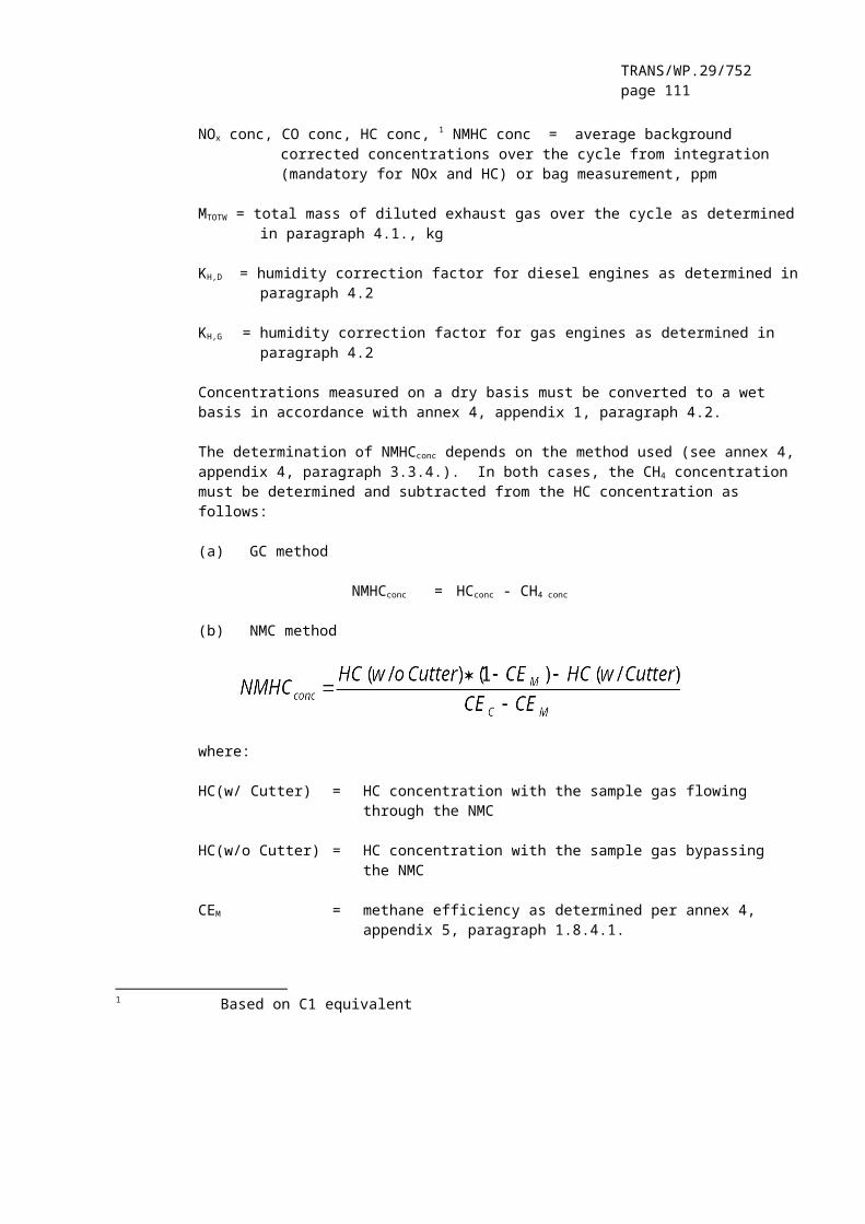
TRANS/WP.29/752page 111
the full deviation when the opacity of the gas being measured is changed in less than 0.1 s.
The electrical response time of the opacimeter must not exceed 0.05 s. The electrical response time is the difference between the times when the opacimeter output reaches 10 and 90 per cent of the full scale when the light source is interrupted or completely extinguished in less than 0.01 s.
5.2.5. Neutral density filters
Any neutral density filter used in conjunction with opacimeter calibration, linearity measurements, or setting span must have its value known to within 1.0 per cent opacity. The filter's nominal value must be checked for accuracy at least yearly using a reference traceable to a national or international standard.
Neutral density filters are precision devices and can easily be damaged during use. Handling should be minimised and, when required, should be done with care to avoid scratching or soiling of the filter.
__________"
Insert new Annex 4 – Appendix 5, to read:
"Annex 4 - Appendix 5
CALIBRATION PROCEDURE
1. CALIBRATION OF THE ANALYTICAL INSTRUMENTS
1.1. Introduction
Each analyser must be calibrated as often as necessary to fulfil the accuracy requirements of this Regulation. The calibration method that must be used is described in this paragraph for the analysers indicated in annex 4, appendix 4, paragraph 3. and annex 4, appendix 7, paragraph 1.
1.2. Calibration gases
The shelf life of all calibration gases must be respected.The expiration date of the calibration gases stated by the manufacturer must be recorded.
1.2.1. Pure gases
The required purity of the gases is defined by the contamination limits given below. The following gases must be available for operation:

TRANS/WP.29/752page 112
Purified nitrogen (Contamination ≤ 1 ppm C1, ≤1 ppm CO, ≤ 400 ppm CO2, ≤ 0.1 ppm NO)
Purified oxygen (Purity 99.5 % vol 02)
Hydrogen-helium mixture (40 ± 2 % hydrogen, balance helium)(Contamination ≤ 1 ppm C1, ≤ 400 ppm CO2)
Purified synthetic air (Contamination ≤ 1 ppm C1, ≤ 1 ppm CO, ≤ 400 ppm CO2, ≤ 0.1 ppm NO) (Oxygen content between 18-21 % vol.)
Purified propane or CO for the CVS verification
1.2.2. Calibration and span gases
Mixtures of gases having the following chemical compositions must be available:
C3H8 and purified synthetic air (see paragraph 1.2.1);
CO and purified nitrogen;
NOx and purified nitrogen (the amount of NO2 contained in this calibration gas must not exceed 5 % of the NO content);
CO2 and purified nitrogen
CH4 and purified synthetic air
C2H6 and purified synthetic air
Note: Other gas combinations are allowed provided the gases do not react with one another.
The true concentration of a calibration and span gas must be within ± 2 per cent of the nominal value. All concentrations of calibration gas must be given on a volume basis (volume percent or volume ppm).The gases used for calibration and span may also be obtained by means of a gas divider, diluting with purified N2 or with purified synthetic air. The accuracy of the mixing device must be such that the concentration of the diluted calibration gases may be determined to within ± 2 per cent.
1.3. Operating procedure for analysers and sampling system
The operating procedure for analysers must follow the start-up and operating instructions of the instrument manufacturer. The minimum requirements given in paragraphs 1.4. to 1.9. must be included.

TRANS/WP.29/752page 113
1.4. Leakage test
A system leakage test must be performed. The probe must be disconnected from the exhaust system and the end plugged. The analyser pump must be switched on. After an initial stabilisation period all flow meters should read zero. If not, the sampling lines must be checked and the fault corrected.
The maximum allowable leakage rate on the vacuum side must be 0.5 per cent of the in-use flow rate for the portion of the system being checked. The analyser flows and bypass flows may be used to estimate the in-use flow rates.
Another method is the introduction of a concentration step change at the beginning of the sampling line by switching from zero to span gas. If after an adequate period of time the reading shows a lower concentration compared to the introduced concentration, this points to calibration or leakage problems.
1.5. Calibration procedure
1.5.1. Instrument assembly
The instrument assembly must be calibrated and calibration curves checked against standard gases. The same gas flow rates must be used as when sampling exhaust.
1.5.2. Warming-up time
The warming-up time should be according to the recommendations of the manufacturer. If not specified, a minimum of two hours is recommended for warming up the analysers.
1.5.3. NDIR and HFID analyser
The NDIR analyser must be tuned, as necessary, and the combustion flame of the HFID analyser must be optimised (paragraph 1.8.1).
1.5.4. Calibration
Each normally used operating range must be calibrated.
Using purified synthetic air (or nitrogen), the CO, CO2, NOx and HC analysers must be set at zero.
The appropriate calibration gases must be introduced to the analysers, the values recorded, and the calibration curve established according to paragraph 1.5.5.
The zero setting must be rechecked and the calibration procedure repeated, if necessary.

TRANS/WP.29/752page 114
1.5.5. Establishment of the calibration curve
1.5.5.1. General guidelines
The analyser calibration curve must be established by at least five calibration points (excluding zero) spaced as uniformly as possible. The highest nominal concentration must be equal to or higher than 90 per cent of full scale.
The calibration curve must be calculated by the method of least squares. If the resulting polynomial degree is greater than 3, the number of calibration points (zero included) must be at least equal to this polynomial degree plus 2.
The calibration curve must not differ by more than ± 2 per cent from the nominal value of each calibration point and by more than ± 1 per cent of full scale at zero.From the calibration curve and the calibration points, it is possible to verify that the calibration has been carried out correctly. The different characteristic parameters of the analyser must be indicated, particularly:
– the measuring range;– the sensitivity;– the date of carrying out the calibration.
1.5.5.2. Calibration below 15 per cent of Full Scale
The analyser calibration curve must be established by at least 4 additional calibration points (excluding zero) spaced nominally equally below 15 per cent of full scale.
The calibration curve is calculated by the method of least squares.
The calibration curve must not differ by more than ± 4 per cent from the nominal value of each calibration point and by more than ± 1 per cent of full scale at zero.
1.5.5.3. Alternative methods
If it can be shown that alternative technology (e.g. computer, electronically controlled range switch, etc.) can give equivalent accuracy, then these alternatives may be used.
1.6. Verification of the calibration
Each normally used operating range must be checked prior to each analysis in accordance with the following procedure.
The calibration must be checked by using a zero gas and a span gas whose nominal value is more than 80 per cent of full scale of the measuring range.
If, for the two points considered, the value found does not differ by more than ± 4 per cent of full scale from the declared reference

TRANS/WP.29/752page 115
value, the adjustment parameters may be modified. Should this not be the case, a new calibration curve must be established in accordance with paragraph 1.5.5.
1.7. Efficiency test of the NOx converter
The efficiency of the converter used for the conversion of NO2 into NO must be tested as given in paragraphs 1.7.1. to 1.7.8.(Figure 6).
Figure 6 Schematic of NO2 converter efficiency device
1.7.1. Test set-up
Using the test set-up as shown in Figure 6 (see also annex 4, appendix 4, paragraph 3.3.5.) and the procedure below, the efficiency of converters can be tested by means of an ozonator.
1.7.2. Calibration
The CLD and the HCLD must be calibrated in the most common operating range following the manufacturer's specifications using zero and span gas (the NO content of which must amount to about 80 per cent of the operating range and the NO2 concentration of the gas mixture to less than 5 per cent of the NO concentration). The NOx analyser must be in the NO mode so that the span gas does not pass through the converter. The indicated concentration has to be recorded.
1.7.3. Calculation
The efficiency of the NOx converter is calculated as follows:

TRANS/WP.29/752page 116
where:
a is the NOx concentration according to paragraph 1.7.6b is the NOx concentration according to paragraph 1.7.7c is the NO concentration according to paragraph 1.7.4d is the NO concentration according to paragraph 1.7.5
1.7.4. Adding of oxygen
Via a T-fitting, oxygen or zero air is added continuously to the gas flow until the concentration indicated is about 20 per cent less than the indicated calibration concentration given in paragraph 1.7.2.(The analyser is in the NO mode). The indicated concentration c must be recorded. The ozonator is kept deactivated throughout the process.
1.7.5. Activation of the ozonator
The ozonator is now activated to generate enough ozone to bring the NO concentration down to about 20 per cent (minimum 10 per cent) of the calibration concentration given in paragraph 1.7.2. The indicated concentration d must be recorded (The analyser is in the NO mode).
1.7.6. NOx mode
The NO analyser is then switched to the NOx mode so that the gas mixture (consisting of NO, NO2, O2 and N2) now passes through the converter. The indicated concentration a must be recorded. (The analyser is in the NOx mode).
1.7.7. Deactivation of the ozonator
The ozonator is now deactivated. The mixture of gases described in paragraph 1.7.6. passes through the converter into the detector. The indicated concentration b must be recorded. (The analyser is in the NOx mode).
1.7.8. NO mode
Switched to NO mode with the ozonator deactivated, the flow of oxygen or synthetic air is also shut off. The NOx reading of the analyser must not deviate by more than ± 5 per cent from the value measured according to paragraph 1.7.2. (The analyser is in the NO mode).
1.7.9. Test interval
The efficiency of the converter must be tested prior to each calibration of the NOx analyser.

TRANS/WP.29/752page 117
1.7.10. Efficiency requirement
The efficiency of the converter must not be less than 90 per cent, but a higher efficiency of 95 per cent is strongly recommended.
Note: If, with the analyser in the most common range, the ozonator cannot give a reduction from 80 per cent to 20 per cent according to paragraph 1.7.5., then the highest range which will give the reduction must be used.
1.8. Adjustment of the FID
1.8.1. Optimisation of the detector response
The FID must be adjusted as specified by the instrument manufacturer. A propane in air span gas should be used to optimise the response on the most common operating range.
With the fuel and air flow rates set at the manufacturer's recommendations, a 350 ± 75 ppm C span gas must be introduced to the analyser. The response at a given fuel flow must be determined from the difference between the span gas response and the zero gas response. The fuel flow must be incrementally adjusted above and below the manufacturer's specification. The span and zero response at these fuel flows must be recorded. The difference between the span and zero response must be plotted and the fuel flow adjusted to the rich side of the curve.
1.8.2. Hydrocarbon response factors
The analyser must be calibrated using propane in air and purified synthetic air, according to paragraph 1.5.
Response factors must be determined when introducing an analyser into service and after major service intervals. The response factor (Rf) for a particular hydrocarbon species is the ratio of the FID C1 reading to the gas concentration in the cylinder expressed by ppm C1.
The concentration of the test gas must be at a level to give a response of approximately 80 per cent of full scale. The concentration must be known to an accuracy of ± 2 per cent in reference to a gravimetric standard expressed in volume. In addition, the gas cylinder must be preconditioned for 24 hours at a temperature of 298 K ± 5 K (25°C ± 5°C).
The test gases to be used and the recommended relative response factor ranges are as follows:
Methane and purified synthetic air 1.00 ≤ Rf ≤ 1.15Propylene and purified synthetic air 0.90 ≤ Rf ≤ 1.1Toluene and purified synthetic air 0.90 ≤ Rf ≤ 1.10
These values are relative to the response factor (Rf) of 1.00 for propane and purified synthetic air.

TRANS/WP.29/752page 118
1.8.3. Oxygen interference check
The oxygen interference check must be determined when introducing an analyser into service and after major service intervals.
The response factor is defined and must be determined as described in paragraph 1.8.2. The test gas to be used and the recommended relative response factor range are as follows:
Propane and nitrogen 0.95 ≤ Rf ≤ 1.05
This value is relative to the response factor (Rf) of 1.00 for propane and purified synthetic air.
The FID burner air oxygen concentration must be within ± 1 mole % of the oxygen concentration of the burner air used in the latest oxygen interference check. If the difference is greater, the oxygen interference must be checked and the analyser adjusted, if necessary.
1.8.4. Efficiency of the non-methane cutter (NMC, for NG fuelled gas engines only)
The NMC is used for the removal of the non-methane hydrocarbons from the sample gas by oxidising all hydrocarbons except methane. Ideally, the conversion for methane is 0 %, and for the other hydrocarbons represented by ethane is 100 %. For the accurate measurement of NMHC, the two efficiencies must be determined and used for the calculation of the NMHC emission mass flow rate (see annex 4, appendix 2, paragraph 4.3.).
1.8.4.1. Methane efficiency
Methane calibration gas must be flown through the FID with and without bypassing the NMC and the two concentrations recorded. The efficiency must be determined as follows:
where:
concw = HC concentration with CH4 flowing through the NMCconcw/o = HC concentration with CH4 bypassing the NMC
1.8.4.2. Ethane efficiency
Ethane calibration gas must be flown through the FID with and without bypassing the NMC and the two concentrations recorded. The efficiency must be determined as follows:
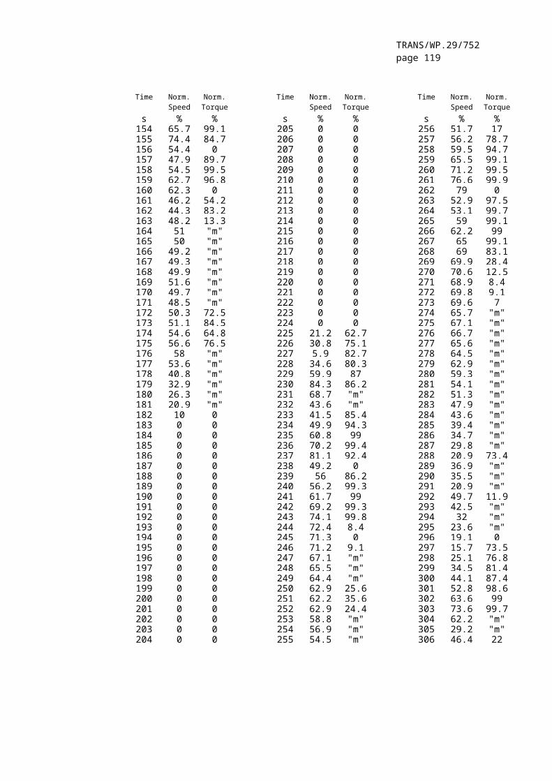
TRANS/WP.29/752page 119
where:
concw = HC concentration with C2H6 flowing through the NMCconcw/o = HC concentration with C2H6 bypassing the NMC
1.9. Interference effects with CO, CO2, and NOx analysers
Gases present in the exhaust other than the one being analysed can interfere with the reading in several ways. Positive interference occurs in NDIR instruments where the interfering gas gives the same effect as the gas being measured, but to a lesser degree. Negative interference occurs in NDIR instruments by the interfering gas broadening the absorption band of the measured gas, and in CLD instruments by the interfering gas quenching the radiation. The interference checks in paragraphs 1.9.1. and 1.9.2. must be performed prior to an analyser’s initial use and after major service intervals.
1.9.1. CO Analyser interference check
Water and CO2 can interfere with the CO analyser performance. Therefore, a CO2 span gas having a concentration of 80 to 100 per cent of full scale of the maximum operating range used during testing must be bubbled through water at room temperature and the analyser response recorded. The analyser response must not be more than 1 per cent of full scale for ranges equal to or above 300 ppm or more than 3 ppm for ranges below 300 ppm.
1.9.2. NOx analyser quench checks
The two gases of concern for CLD (and HCLD) analysers are CO2 and water vapour. Quench responses to these gases are proportional to their concentrations, and therefore require test techniques to determine the quench at the highest expected concentrations experienced during testing.
1.9.2.1. CO2 quench check
A CO2 span gas having a concentration of 80 to 100 per cent of full scale of the maximum operating range must be passed through the NDIR analyser and the CO2 value recorded as A. It must then be diluted approximately 50 per cent with NO span gas and passed through the NDIR and (H)CLD, with the CO2 and NO values recorded as B and C, respectively. The CO2 must then be shut off and only the NO span gas be passed through the (H)CLD and the NO value recorded as D.
The quench, which must not be greater than 3 per cent of full scale, must be calculated as follows:
where:
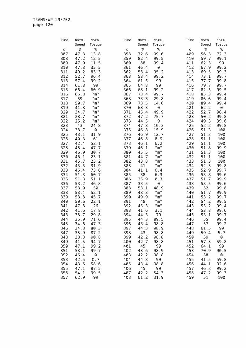
TRANS/WP.29/752page 120
A is the undiluted CO2 concentration measured with NDIR in per centB is the diluted CO2 concentration measured with NDIR in per centC is the diluted NO concentration measured with (H)CLD in ppmD is the undiluted NO concentration measured with (H)CLD in ppm
Alternative methods of diluting and quantifying of CO2 and NO span gas values such as dynamic mixing/blending can be used.
1.9.2.2. Water quench check
This check applies to wet gas concentration measurements only. Calculation of water quench must consider dilution of the NO span gas with water vapour and scaling of water vapour concentration of the mixture to that expected during testing.
A NO span gas having a concentration of 80 to 100 per cent of full scale of the normal operating range must be passed through the (H)CLD and the NO value recorded as D. The NO span gas must then be bubbled through water at room temperature and passed through the (H)CLD and the NO value recorded as C. The analyser’s absolute operating pressure and the water temperature must be determined and recorded as E and F, respectively. The mixture's saturation vapour pressure that corresponds to the bubbler water temperature F must be determined and recorded as G. The water vapour concentration (H, in %) of the mixture must be calculated as follows:
H = 100*( G/E)
The expected diluted NO span gas (in water vapour) concentration (De) must be calculated as follows:
De = D* ( 1- H/100 )
For diesel exhaust, the maximum exhaust water vapour concentration (Hm, in %) expected during testing must be estimated, under the assumption of a fuel atom H/C ratio of 1.8:1. from the undiluted CO2 span gas concentration (A, as measured in paragraph 1.9.2.1) as follows:
Hm = 0.9*A
The water quench, which must not be greater than 3 per cent, must be calculated as follows:
% Quench = 100 * ( ( De - C )/De) * (Hm/H)
where:
De is the expected diluted NO concentration in ppmC is the diluted NO concentration in ppm Hm is the maximum water vapour concentration in %H is the actual water vapour concentration in %
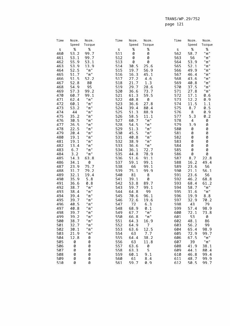
TRANS/WP.29/752page 121
Note: It is important that the NO span gas contains minimal NO2 concentration for this check, since absorption of NO2 in water has not been accounted for in the quench calculations.

TRANS/WP.29/752page 122
1.10. Calibration intervals
The analysers must be calibrated according to paragraph 1.5. at least every 3 months or whenever a system repair or change is made that could influence calibration.
2. CALIBRATION OF THE CVS-SYSTEM
2.1. General
The CVS system must be calibrated by using an accurate flowmeter traceable to national or international standards and a restricting device. The flow through the system must be measured at different restriction settings, and the control parameters of the system must be measured and related to the flow.
Various types of flowmeters may be used, e. g. calibrated venturi, calibrated laminar flowmeter, calibrated turbinemeter.
2.2. Calibration of the positive displacement pump (PDP)
All parameters related to the pump must be simultaneously measured with the parameters related to the flowmeter which is connected in series with the pump. The calculated flow rate (in m3/min at pump inlet, absolute pressure and temperature) must be plotted versus a correlation function which is the value of a specific combination of pump parameters. The linear equation which relates the pump flow and the correlation function must then be determined. If a CVS has a multiple speed drive, the calibration must be performed for each range used. Temperature stability must be maintained during calibration.
2.2.1. Data analysis
The air flow rate (Qs) at each restriction setting (minimum 6 settings) must be calculated in standard m3/min from the flowmeter data using the manufacturer's prescribed method. The air flow rate must then be converted to pump flow (V0) in m3/rev at absolute pump inlet temperature and pressure as follows:
where:
Qs = air flow rate at standard conditions (101.3 kPa, 273 K), m3/sT = temperature at pump inlet, KpA = absolute pressure at pump inlet (pB - p1), kPan = pump speed, rev/s
To account for the interaction of pressure variations at the pump and the pump slip rate, the correlation function (X0) between pump speed, pressure differential from pump inlet to pump outlet and absolute pump outlet pressure must be calculated as follows:

TRANS/WP.29/752page 123
where:
ΔpP = pressure differential from pump inlet to pump outlet, kPapA = absolute outlet pressure at pump outlet, kPa
A linear least-square fit must be performed to generate the calibration equation as follows:
V0 = D0 - m * (X0)
D0 and m are the intercept and slope constants, respectively, describing the regression lines.
For a CVS system with multiple speeds, the calibration curves generated for the different pump flow ranges must be approximately parallel, and the intercept values (D0) must increase as the pump flow range decreases.
The calculated values from the equation must be within ± 0.5 per cent of the measured value of V0. Values of m will vary from one pump to another. Particulate influx over time will cause the pump slip to decrease, as reflected by lower values for m. Therefore, calibration must be performed at pump start-up, after major maintenance, and if the total system verification (paragraph 2.4) indicates a change of the slip rate.
2.3. Calibration of the critical flow venturi (CFV)
Calibration of the CFV is based upon the flow equation for a critical venturi. Gas flow is a function of inlet pressure and temperature, as shown below:
where:
Kv = calibration coefficientpA = absolute pressure at venturi inlet, kPaT = temperature at venturi inlet, K
2.3.1. Data Analysis
The air flow rate (Qs) at each restriction setting (minimum 8 settings) must be calculated in standard m3/min from the flowmeter data using the manufacturer's prescribed method. The calibration coefficient must be calculated from the calibration data for each setting as follows:

TRANS/WP.29/752page 124
where:
Qs = air flow rate at standard conditions (101.3 kPa, 273 K), m3/s T = temperature at the venturi inlet, KpA = absolute pressure at venturi inlet, kPa
To determine the range of critical flow, Kv must be plotted as a function of venturi inlet pressure. For critical (choked) flow, Kv will have a relatively constant value. As pressure decreases (vacuum increases), the venturi becomes unchoked and Kv decreases, which indicates that the CFV is operated outside the permissible range.
For a minimum of eight points in the region of critical flow, the average Kv and the standard deviation must be calculated. The standard deviation must not exceed ± 0.3 per cent of the average KV.
2.4. Total system verification
The total accuracy of the CVS sampling system and analytical system must be determined by introducing a known mass of a pollutant gas into the system while it is being operated in the normal manner. The pollutant is analysed, and the mass calculated according to annex 4, appendix 2, paragraph 4.3., except in the case of propane where a factor of 0.000472 is used in place of 0.000479 for HC. Either of the following two techniques must be used.
2.4.1. Metering with a critical flow orifice
A known quantity of pure gas (carbon monoxide or propane) must be fed into the CVS system through a calibrated critical orifice. If the inlet pressure is high enough, the flow rate, which is adjusted by means of the critical flow orifice, is independent of the orifice outlet pressure (≡ critical flow). The CVS system must be operated as in a normal exhaust emission test for about 5 to 10 minutes. A gas sample must be analysed with the usual equipment (sampling bag or integrating method), and the mass of the gas calculated. The mass so determined must be within ± 3 per cent of the known mass of the gas injected.
2.4.2. Metering by means of a gravimetric technique
The weight of a small cylinder filled with carbon monoxide or propane must be determined with a precision of ± 0.01 gram. For about 5 to 10 minutes, the CVS system must be operated as in a normal exhaust emission test, while carbon monoxide or propane is injected into the system. The quantity of pure gas discharged must be determined by means of differential weighing. A gas sample must be analysed with the usual equipment (sampling bag or integrating method), and the mass of the gas calculated. The mass so determined must be within ± 3 per cent of the known mass of the gas injected.
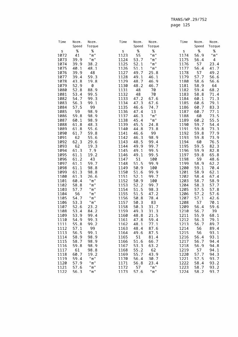
TRANS/WP.29/752page 125
3. CALIBRATION OF THE PARTICULATE MEASURING SYSTEM
3.1. Introduction
Each component must be calibrated as often as necessary to fulfil the accuracy requirements of this Regulation. The calibration method to be used is described in this paragraph for the components indicated in annex 4, appendix 4, paragraph 4. and annex 4, appendix 7, paragraph 2.
3.2. Flow measurement
The calibration of gas flow meters or flow measurement instrumentation must be traceable to international and/or national standards. The maximum error of the measured value must be within ± 2 per cent of reading.
If the gas flow is determined by differential flow measurement, the maximum error of the difference must be such that the accuracy of GEDF
is within ± 4 per cent (see also annex 4, appendix 7, paragraph 2.2.1., EGA). It can be calculated by taking the Root-Mean-Square of the errors of each instrument.
3.3. Checking the partial flow conditions
The range of the exhaust gas velocity and the pressure oscillations must be checked and adjusted according to the requirements of annex 4, appendix 7, paragraph 2.2.1., EP, if applicable.
3.4. Calibration intervals
The flow measurement instrumentation must be calibrated at least every 3 months or whenever a system repair or change is made that could influence calibration.
4. CALIBRATION OF THE SMOKE MEASUREMENT EQUIPMENT
4.1. Introduction
The opacimeter must be calibrated as often as necessary to fulfil the accuracy requirements of this Regulation. The calibration method to be used is described in this paragraph for the components indicated in annex 4, appendix 4, paragraph 5. and annex 4, appendix 7, paragraph 3.
4.2. Calibration procedure
4.2.1. Warming-up time
The opacimeter must be warmed up and stabilised according to the manufacturer's recommendations. If the opacimeter is equipped with a purge air system to prevent sooting of the instrument optics, this system should also be activated and adjusted according to the manufacturer's recommendations.
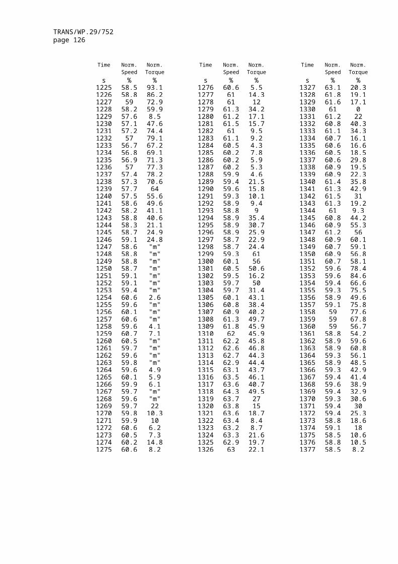
TRANS/WP.29/752page 126
4.2.2. Establishment of the linearity response
The linearity of the opacimeter must be checked in the opacity readout mode as per the manufacturer's recommendations. Three neutral density filters of known transmittance, which must meet the requirements of annex 4, appendix 4, paragraph 5.2.5., must be introduced to the opacimeter and the value recorded. The neutral density filters must have nominal opacities of approximately 10 %, 20 % and 40 %.
The linearity must not differ by more than ± 2 per cent opacity from the nominal value of the neutral density filter. Any non-linearity exceeding the above value must be corrected prior to the test.
4.3. Calibration intervals
The opacimeter must be calibrated according to paragraph 4.2.2. at least every 3 months or whenever a system repair or change is made that could influence calibration.
__________"
Insert new Annex 4 – Appendix 6, to read:
"A nnex 4 – Appendix 6
ANALYTICAL AND SAMPLING SYSTEMS
1. DETERMINATION OF THE GASEOUS EMISSIONS
1.1. Introduction
Paragraph 1.2. and figures 7 and 8 contain detailed descriptions of the recommended sampling and analysing systems. Since various configurations can produce equivalent results, exact conformance with figures 7 and 8 is not required. Additional components such as instruments, valves, solenoids, pumps, and switches may be used to provide additional information and coordinate the functions of the component systems. Other components which are not needed to maintain the accuracy on some systems, may be excluded if their exclusion is based upon good engineering judgement.

TRANS/WP.29/752page 127
zero gas
span gas
zero gas
span gas
zero gas
zero gasV1
V1
F1 F2
F1 F2
P
P
T1
T1
SP1
SP1
optional 2 sampling probes
EPT2 G1
HC
air fuel
vent
vent
vent
vent
vent
vent
vent
V2
R3
R1 R2
FL1
T5
B
V12 V11
V10CO
CO2
C
T3 G2
V4
V5
FL5
FL6
FL3
T4
G3
V12 V11
T5
V8
V6 V7 V9
R4
FL4
FL2
HSL1
HSL2
HSL1
SL
V3NO
R5
B
zero gas
span gas
zero gas
span gas
Figure 7 - Flow diagram of raw exhaust gas analysis system for CO, CO2, NOx, HC ESC only
1.2. Description of the analytical system
An analytical system for the determination of the gaseous emissions in the raw (Figure 7, ESC only) or diluted (Figure 8. ETC and ESC) exhaust gas is described based on the use of:
HFID analyser for the measurement of hydrocarbons; NDIR analysers for the measurement of carbon monoxide and carbon
dioxide; HCLD or equivalent analyser for the measurement of the oxides of
nitrogen;
The sample for all components may be taken with one sampling probe or with two sampling probes located in close proximity and internally split to the different analysers. Care must be taken that no condensation of exhaust components (including water and sulphuric acid) occurs at any point of the analytical system.

TRANS/WP.29/752page 128
zero gas
span gas
zero gas
span gas
zero gas
span gas
zero gas
span gas
zero gas
V1
F1 F2
F1 F2
P
P
T1
T1
SP2
SP3
T2 G1
HC
air fuel
vent
vent
vent
vent
vent
vent
vent
V2
R3
R1 R2
FL1
T5
B
V13 V12
V11CO
CO2
C
T3 G2
V4
V5
FL5
FL6
FL3
T4
G3
V9
V7 V8 V10
R4
FL4
FL2
HSL1
HSL2
HSL1
SL
V3NO
R5
V1
PSP
to PSS see figure 21
same planesee fig. 21
BK
BKBG
DTsee fig. 20
V14
Figure 8 - Flow diagram of diluted exhaust gas analysis system for CO, CO2, NOx, HC (ETC, optional for Economic and Social Committee)
1.2.1. Components of figures 7 and 8
EP Exhaust pipe
SP1 Exhaust gas sampling probe (Figure 7 only)
A stainless steel straight closed end multi-hole probe is recommended. The inside diameter must not be greater than the inside diameter of the sampling line. The wall thickness of the probe must not be greater than 1 mm. There must be a minimum of 3 holes in 3 different radial planes sized to sample approximately the same flow. The probe must extend across at least 80 per cent of the diameter of the exhaust pipe. One or two sampling probes may be used.
SP2 Diluted exhaust gas HC sampling probe (Figure 8 only)
The probe must:
be defined as the first 254 mm to 762 mm of the heated sampling line HSL1;

TRANS/WP.29/752page 129
have a 5 mm minimum inside diameter;
be installed in the dilution tunnel DT (see paragraph 2.3., Figure 20) at a point where the dilution air and exhaust gas are well mixed (i.e. approximately 10 tunnel diameters downstream of the point where the exhaust enters the dilution tunnel);
be sufficiently distant (radially) from other probes and the tunnel wall so as to be free from the influence of any wakes or eddies;
be heated so as to increase the gas stream temperature to 463 K ± 10 K (190°C ± 10°C) at the exit of the probe.
SP3 Diluted exhaust gas CO, CO2, NOx sampling probe (Figure 8 only)
The probe must:
be in the same plane as SP 2;
be sufficiently distant (radially) from other probes and the tunnel wall so as to be free from the influence of any wakes or eddies;
be heated and insulated over its entire length to a minimum temperature of 328 K (55°C) to prevent water condensation.
HSL1 Heated sampling line
The sampling line provides a gas sample from a single probe to the split point(s) and the HC analyser.
The sampling line must:
have a 5 mm minimum and a 13.5 mm maximum inside diameter;
be made of stainless steel or PTFE.
maintain a wall temperature of 463 K ± 10 K (190°C ± 10°C) as measured at every separately controlled heated section, if the temperature of the exhaust gas at the sampling probe is equal to or below 463 K (190°C);
maintain a wall temperature greater than 453 K (180°C), if the temperature of the exhaust gas at the sampling probe is above 463 K (190°C);
maintain a gas temperature of 463 K ± 10 K (190°C ± 10°C) immediately before the heated filter F2 and the HFID;
TRANS/WP.29/752page 130
HSL2 Heated NOx sampling line
The sampling line must:
maintain a wall temperature of 328 K to 473 K (55°C to 200°C), up to the converter C when using a cooling bath B, and up to the analyser when a cooling bath B is not used.
be made of stainless steel or PTFE.
SL Sampling line for CO and CO2
The line must be made of PTFE or stainless steel. It may be heated or unheated.
BK Background bag (optional; Figure 8 only)
For the sampling of the background concentrations
BG Sample bag (optional; Figure 8 CO and CO2 only)
For the sampling of the sample concentrations.
F1 Heated pre-filter (optional)
The temperature must be the same as HSL1.
F2 Heated filter
The filter must extract any solid particles from the gas sample prior to the analyser. The temperature must be the same as HSL1. The filter must be changed as needed.
P Heated sampling pump
The pump must be heated to the temperature of HSL1.
HC Heated flame ionisation detector (HFID) for the determination of the hydrocarbons.
The temperature must be kept at 453 K to 473 K (180°C to 200°C).
CO, CO2 NDIR analysers for the determination of carbon monoxide and carbon dioxide (optional for the determination of the dilution ratio for PT measurement).
NO CLD or HCLD analyser for the determination of the oxides of nitrogen.
If a HCLD is used it must be kept at a temperature of 328 K to 473 K (55°C to 200°C).

TRANS/WP.29/752page 131
C Converter
A converter must be used for the catalytic reduction of NO2 to NO prior to analysis in the CLD or HCLD.
B Cooling bath (optional)
To cool and condense water from the exhaust sample. The bath must be maintained at a temperature of 273 K to 277 K (0°C to 4°C) by ice or refrigeration. It is optional if the analyser is free from water vapour interference as determined in annex 4, appendix 5, paragraphs 1.9.1. and 1.9.2. If water is removed by condensation, the sample gas temperature or dew point must be monitored either within the water trap or downstream. The sample gas temperature or dew point must not exceed 280 K (7°C). Chemical dryers are not allowed for removing water from the sample.
T1, T2, T3 Temperature sensor
To monitor the temperature of the gas stream.
T4 Temperature sensor
To monitor the temperature of the NO2 - NO converter.
T5 Temperature sensor
To monitor the temperature of the cooling bath.
G1, G2, G3 Pressure gauge
To measure the pressure in the sampling lines.
R1, R2 Pressure regulator
To control the pressure of the air and the fuel, respectively, for the HFID.
R3, R4, R5 Pressure regulator
To control the pressure in the sampling lines and the flow to the analysers.
FL1, FL2, FL3 Flowmeter
To monitor the sample by-pass flow rate.
FL4 to FL6 Flowmeter (optional)
To monitor the flow rate through the analysers.

TRANS/WP.29/752page 132
V1 to V5 Selector valve
Suitable valving for selecting sample, span gas or zero gas flow to the analysers.
V6, V7 Solenoid valve
To by-pass the NO2 - NO converter.
V8 Needle valve
To balance the flow through the NO2 - NO converter C and the by-pass.
V9, V10 Needle valve
To regulate the flows to the analysers.
V11, V12 Toggle valve (optional)
To drain the condensate from the bath B.
1.3. NMHC analysis (NG fuelled gas engines only)
1.3.1. Gas chromatographic method (GC, Figure 9)
When using the GC method, a small measured volume of a sample is injected onto an analytical column through which it is swept by an inert carrier gas. The column separates various components according to their boiling points so that they elute from the column at different times. They then pass through a detector which gives an electrical signal that depends on their concentration. Since it is not a continuous analysis technique, it can only be used in conjunction with the bag sampling method as described in annex 4, appendix 4, paragraph 3.4.2.
For NMHC an automated GC with a FID must be used. The exhaust gas must be sampled into a sampling bag from which a part must be taken and injected into the GC. The sample is separated into two parts (CH4/Air/CO and NMHC/CO2/H2O) on the Porapak column. The molecular sieve column separates CH4 from the air and CO before passing it to the FID where its concentration is measured. A complete cycle from injection of one sample to injection of a second can be made in 30 s. To determine NMHC, the CH4 concentration must be subtracted from the total HC concentration (see annex 4, appendix 2, paragraph 4.3.1.).
Figure 9 shows a typical GC assembled to routinely determine CH4. Other GC methods can also be used based on good engineering judgement.

TRANS/WP.29/752page 133
123456789
10
SLP
MSC
P
DF4 F1
V3
V2
V4
V6
V7
V8
F5
F3
R1
R2
R3
Oven
vent
F2
FM1
vent
to x
to yx
y10
V1
PC
sample span gas
fuel inlet
air inlet
HC
FC
Figure 9 - Flow diagram for methane analysis (GC method)
Components of Figure 9
PC Porapak column
Porapak N, 180/300 µm (50/80 mesh), 610 mm length x 2.16 mm ID must be used and conditioned at least 12 h at 423 K (150°C) with carrier gas prior to initial use.
MSC Molecular sieve column
Type 13X, 250/350 µm (45/60 mesh), 1220 mm length x 2.16 mm ID must be used and conditioned at least 12 h at 423 K (150°C) with carrier gas prior to initial use.
OV Oven
To maintain columns and valves at stable temperature for analyser operation, and to condition the columns at 423 K (150°C).
SLP Sample loop
A sufficient length of stainless steel tubing to obtain approximately 1 cm³ volume.

TRANS/WP.29/752page 134
P Pump
To bring the sample to the gas chromatograph.
D Dryer
A dryer containing molecular sieve must be used to remove water and other contaminants which might be present in the carrier gas.
HC Flame ionisation detector (FID) to measure the concentration of methane.
V1 Sample injection valve
To inject the sample taken from the sampling bag via SL of Figure 8. It must be low dead volume, gas tight, and heatable to 423 K (150°C).
V3 Selector valve
To select span gas, sample, or no flow.
V2, V4, V5, V6, V7, V8 Needle valve
To set the flows in the system.
R1, R2, R3 Pressure regulator
To control the flows of the fuel (= carrier gas), the sample, and the air, respectively.
FC Flow capillary
To control the rate of air flow to the FID
G1, G2, G3 Pressure gauge
To control the flows of the fuel (= carrier gas), the sample, and the air, respectively.
F1, F2, F3, F4, F5 Filter
Sintered metal filters to prevent grit from entering the pump or the instrument.
FL1 Flowmeter
To measure the sample bypass flow rate.
1.3.2. Non-methane cutter method (NMC, Figure 10)
The cutter oxidises all hydrocarbons except CH4 to CO2 and H2O, so that by passing the sample through the NMC only CH4 is detected by the FID. If bag sampling is used, a flow diverter system must be installed at SL (see paragraph 1.2., Figure 8) with which the flow

TRANS/WP.29/752page 135
can be alternatively passed through or around the cutter according to the upper part of Figure 10. For NMHC measurement, both values (HC and CH4) must be observed on the FID and recorded. If the integration method is used, an NMC in line with a second FID must be installed parallel to the regular FID into HSL1 (see paragraph 1.2., Figure 8) according to the lower part of Figure 10. For NMHC measurement, the values of the two FID's (HC and CH4) must be observed and recorded.
The cutter must be characterised at or above 600 K (327°C) prior to test work with respect to its catalytic effect on CH4 and C2H6 at H2O values representative of exhaust stream conditions. The dew point and O2 level of the sampled exhaust stream must be known. The relative response of the FID to CH4 must be recorded (see annex 4, appendix 5, paragraph 1.8.2.).
zero
span
sample V1 V2 V3NMC
SL (see figure 8)
vent
HC
V4
zero
span
sample V1 V2NMC
HSL1 (see figure 8)
vent
HC
ventHC
Bag Sampling Method
Integrating Method
Figure 10 - Flow diagram for methane analysis with the non-methane cutter (NMC)
Components of Figure 10
NMC Non-methane cutter
To oxidise all hydrocarbons except methane.
HC Heated flame ionisation detector (HFID)
To measure the HC and CH4 concentrations. The temperature must be kept at 453 K to 473 K (180°C to 200°C).

TRANS/WP.29/752page 136
V1 Selector valve
To select sample, zero and span gas. V1 is identical with V2 of Figure 8.
V2, V3 Solenoid valve
To by-pass the NMC
V4 Needle valve
To balance the flow through the NMC and the by-pass.
R1 Pressure regulator
To control the pressure in the sampling line and the flow to the HFID. R1 is identical with R3 of Figure 8.
FL1 Flowmeter
To measure the sample by-pass flow rate. FL1 is identical with FL1 of Figure 8.
2. EXHAUST GAS DILUTION AND DETERMINATION OF THE PARTICULATES
2.1. Introduction
Paragraphs 2.2., 2.3. and 2.4. and figures 11 to 22 contain detailed descriptions of the recommended dilution and sampling systems. Since various configurations can produce equivalent results, exact conformance with these figures is not required. Additional components such as instruments, valves, solenoids, pumps, and switches may be used to provide additional information and coordinate the functions of the component systems. Other components which are not needed to maintain the accuracy on some systems, may be excluded if their exclusion is based upon good engineering judgement.
2.2. Partial flow dilution system
A dilution system is described in figures 11 to 19 based upon the dilution of a part of the exhaust stream. Splitting of the exhaust stream and the following dilution process may be done by different dilution system types. For subsequent collection of the particulates, the entire dilute exhaust gas or only a portion of the dilute exhaust gas is passed to the particulate sampling system (paragraph 2.4., Figure 21). The first method is referred to as total sampling type, the second method as fractional sampling type.
The calculation of the dilution ratio depends upon the type of system used. The following types are recommended:
Isokinetic systems (Figures 11, 12)
With these systems, the flow into the transfer tube is matched to the bulk exhaust flow in terms of gas velocity and/or pressure, thus

TRANS/WP.29/752page 137
requiring an undisturbed and uniform exhaust flow at the sampling probe. This is usually achieved by using a resonator and a straight approach tube upstream of the sampling point. The split ratio is then calculated from easily measurable values like tube diameters. It should be noted that isokinesis is only used for matching the flow conditions and not for matching the size distribution. The latter is typically not necessary, as the particles are sufficiently small as to follow the fluid streamlines.
Flow controlled systems with concentration measurement (Figures 13 to 17)
With these systems, a sample is taken from the bulk exhaust stream by adjusting the dilution air flow and the total dilute exhaust flow. The dilution ratio is determined from the concentrations of tracer gases, such as CO2 or NOx,naturally occurring in the engine exhaust. The concentrations in the dilute exhaust gas and in the dilution air are measured, whereas the concentration in the raw exhaust gas can be either measured directly or determined from fuel flow and the carbon balance equation, if the fuel composition is known. The systems may be controlled by the calculated dilution ratio (figures 13, 14) or by the flow into the transfer tube (figures 12, 13, 14).
Flow controlled systems with flow measurement (Figures 18, 19)
With these systems, a sample is taken from the bulk exhaust stream by setting the dilution air flow and the total dilute exhaust flow. The dilution ratio is determined from the difference of the two flow rates. Accurate calibration of the flow meters relative to one another is required, since the relative magnitude of the two flow rates can lead to significant errors at higher dilution ratios (of 15 and above). Flow control is very straightforward by keeping the dilute exhaust flow rate constant and varying the dilution air flow rate, if needed.
When using partial flow dilution systems, attention must be paid to avoiding the potential problems of loss of particulates in the transfer tube, ensuring that a representative sample is taken from the engine exhaust, and determination of the split ratio. The systems described pay attention to these critical areas.

TRANS/WP.29/752page 138
see figure 21
DAF
EP
TT
DT
dPSP
PB FM1
ISP
FC1
l > 10*d
air
exhaust
PTT
to particulatesamplingsystem
SB
vent
DPTdelta p
Figure 11 - Partial flow dilution system with isokinetic probe and fractional sampling (SB control)
Raw exhaust gas is transferred from the exhaust pipe EP to the dilution tunnel DT through the transfer tube TT by the isokinetic sampling probe ISP. The differential pressure of the exhaust gas between exhaust pipe and inlet to the probe is measured with the pressure transducer DPT. This signal is transmitted to the flow controller FC1 that controls the suction blower SB to maintain a differential pressure of zero at the tip of the probe. Under these conditions, exhaust gas velocities in EP and ISP are identical, and the flow through ISP and TT is a constant fraction (split) of the exhaust gas flow. The split ratio is determined from the cross sectional areas of EP and ISP. The dilution air flow rate is measured with the flow measurement device FM1. The dilution ratio is calculated from the dilution air flow rate and the split ratio.

TRANS/WP.29/752page 139
DAF
EP
TT DT
d
PB
FM1
ISP
delta p FC1DPT
l > 10*d
air
exhaust
PSP
PTT
see figure 21 to particulatesamplingsystem
ventSB
Figure 12 - Partial flow dilution system with isokinetic probe and fractional sampling (PB control)
Raw exhaust gas is transferred from the exhaust pipe EP to the dilution tunnel DT through the transfer tube TT by the isokinetic sampling probe ISP. The differential pressure of the exhaust gas between exhaust pipe and inlet to the probe is measured with the pressure transducer DPT. This signal is transmitted to the flow controller FC1 that controls the pressure blower PB to maintain a differential pressure of zero at the tip of the probe. This is done by taking a small fraction of the dilution air whose flow rate has already been measured with the flow measurement device FM1, and feeding it to TT by means of a pneumatic orifice. Under these conditions, exhaust gas velocities in EP and ISP are identical, and the flow through ISP and TT is a constant fraction (split) of the exhaust gas flow. The split ratio is determined from the cross sectional areas of EP and ISP. The dilution air is sucked through DT by the suction blower SB, and the flow rate is measured with FM1 at the inlet to DT. The dilution ratio is calculated from the dilution air flow rate and the split ratio.
TRANS/WP.29/752page 140
DAF
EP
SP
TT
DT
d
PB
l > 10*d
EGA EGA
EGA
air
exhaust
see figure 21 to particulatesamplingsystem
PSP
PTT
SB
vent
optionalto PB or SB
FC2
Figure 13 - Partial flow dilution system with CO2 or NOx concentration measurement and fractional sampling
Raw exhaust gas is transferred from the exhaust pipe EP to the dilution tunnel DT through the sampling probe SP and the transfer tube TT. The concentrations of a tracer gas (CO2 or NOx) are measured in the raw and diluted exhaust gas as well as in the dilution air with the exhaust gas analyser(s) EGA. These signals are transmitted to the flow controller FC2 that controls either the pressure blower PB or the suction blower SB to maintain the desired exhaust split and dilution ratio in DT. The dilution ratio is calculated from the tracer gas concentrations in the raw exhaust gas, the diluted exhaust gas, and the dilution air.

TRANS/WP.29/752page 141
DAF
EP
SP
TT
DT
d
PB
EGA EGA
G FUEL
exhaust
air
PTT
details see figure 21
FH
P
optional to P
PSS
optional from FC2
FC2
Figure 14 - Partial flow dilution system with CO2 concentration measurement, carbon balance and total sampling
Raw exhaust gas is transferred from the exhaust pipe EP to the dilution tunnel DT through the sampling probe SP and the transfer tube TT. The CO2 concentrations are measured in the diluted exhaust gas and in the dilution air with the exhaust gas analyser(s) EGA. The CO2 and fuel flow GFUEL signals are transmitted either to the flow controller FC2, or to the flow controller FC3 of the particulate sampling system (see Figure 21). FC2 controls the pressure blower PB, FC3 the sampling pump P (see Figure 21), thereby adjusting the flows into and out of the system so as to maintain the desired exhaust split and dilution ratio in DT. The dilution ratio is calculated from the CO2 concentrations and GFUEL using the carbon balance assumption.

TRANS/WP.29/752page 142
DAF
EP
SP
TT
DT
d
PB l > 10*d
EGA
EGA
air
exhaust
EGA
see figure 21 to particulatesamplingsystem
ventPSP
PTT
VN
Figure 15 - Partial flow dilution system with single venturi, concentration measurement and fractional sampling
Raw exhaust gas is transferred from the exhaust pipe EP to the dilution tunnel DT through the sampling probe SP and the transfer tube TT due to the negative pressure created by the venturi VN in DT. The gas flow rate through TT depends on the momentum exchange at the venturi zone, and is therefore affected by the absolute temperature of the gas at the exit of TT. Consequently, the exhaust split for a given tunnel flow rate is not constant, and the dilution ratio at low load is slightly lower than at high load. The tracer gas concentrations (CO2 or NOx) are measured in the raw exhaust gas, the diluted exhaust gas, and the dilution air with the exhaust gas analyser(s) EGA, and the dilution ratio is calculated from the values so measured.

TRANS/WP.29/752page 143
DAF
TT
DT
d
PB
l > 10*d
EGA
EGA
PCV1
PCV2 HE
EP
air
exhaust
PSP
EGA
PTTsee figure 21 to particulate
samplingsystem
vent
SB
FD1FD2
Figure 16 - Partial flow dilution system with twin venturi or twin orifice, concentration measurement and fractional sampling
Raw exhaust gas is transferred from the exhaust pipe EP to the dilution tunnel DT through the sampling probe SP and the transfer tube TT by a flow divider that contains a set of orifices or venturis. The first one (FD1) is located in EP, the second one (FD2) in TT. Additionally, two pressure control valves (PCV1 and PCV2) are necessary to maintain a constant exhaust split by controlling the back-pressure in EP and the pressure in DT. PCV1 is located downstream of SP in EP, PCV2 between the pressure blower PB and DT. The tracer gas concentrations (CO2 or NOx) are measured in the raw exhaust gas, the diluted exhaust gas, and the dilution air with the exhaust gas analyser(s) EGA. They are necessary for checking the exhaust split, and may be used to adjust PCV1 and PCV2 for precise split control. The dilution ratio is calculated from the tracer gas concentrations.

TRANS/WP.29/752page 144
Figure 17 - Partial flow dilution system with multiple tube splitting, concentration measurement and fractional sampling
Raw exhaust gas is transferred from the exhaust pipe EP to the dilution tunnel DT through the transfer tube TT by the flow divider FD3 that consists of a number of tubes of the same dimensions (same diameter, length and bend radius) installed in EP. The exhaust gas through one of these tubes is lead to DT, and the exhaust gas through the rest of the tubes is passed through the damping chamber DC. Thus, the exhaust split is determined by the total number of tubes. A constant split control requires a differential pressure of zero between DC and the outlet of TT, which is measured with the differential pressure transducer DPT. A differential pressure of zero is achieved by injecting fresh air into DT at the outlet of TT. The tracer gas concentrations (CO2 or NOx) are measured in the raw exhaust gas, the diluted exhaust gas, and the dilution air with the exhaust gas analyser(s) EGA. They are necessary for checking the exhaust split and may be used to control the injection air flow rate for precise split control. The dilution ratio is calculated from the tracer gas concentrations.

TRANS/WP.29/752page 145
DAF
EP
SP
TT
DT
d
FM1
FC2
GEXH
orGAIR
GFUELor
exhaust
vent
details see figure 21
FH
P
PSS
PTT
optional to P (PSS)
Figure 18 - Partial flow dilution system with flow control and total sampling
Raw exhaust gas is transferred from the exhaust pipe EP to the dilution tunnel DT through the sampling probe SP and the transfer tube TT. The total flow through the tunnel is adjusted with the flow controller FC3 and the sampling pump P of the particulate sampling system (see Figure 18). The dilution air flow is controlled by the flow controller FC2, which may use GEXHW, GAIRW, or GFUEL as command signals, for the desired exhaust split. The sample flow into DT is the difference of the total flow and the dilution air flow. The dilution air flow rate is measured with the flow measurement device FM1, the total flow rate with the flow measurement device FM3 of the particulate sampling system (see Figure 21). The dilution ratio is calculated from these two flow rates.
TRANS/WP.29/752page 146
DAF
EP
SP
TT
DT d
PB FM1
l > 10*d
GEXHor
GAIR
GFUELor
SB
FM2
FC2
air
exhaust
to PB or SB
PSP
PTT
vent
see figure 21 to particulatesamplingsystem
see figure 21
Figure 19 - Partial flow dilution system with flow control and fractional sampling
Raw exhaust gas is transferred from the exhaust pipe EP to the dilution tunnel DT through the sampling probe SP and the transfer tube TT. The exhaust split and the flow into DT is controlled by the flow controller FC2 that adjusts the flows (or speeds) of the pressure blower PB and the suction blower SB, accordingly. This is possible since the sample taken with the particulate sampling system is returned into DT. GEXHW, GAIRW, or GFUEL may be used as command signals for FC2. The dilution air flow rate is measured with the flow measurement device FM1, the total flow with the flow measurement device FM2. The dilution ratio is calculated from these two flow rates.

TRANS/WP.29/752page 147
2.2.1. Components of figures 11 to 19
EP Exhaust pipe
The exhaust pipe may be insulated. To reduce the thermal inertia of the exhaust pipe a thickness to diameter ratio of 0.015 or less is recommended. The use of flexible sections must be limited to a length to diameter ratio of 12 or less. Bends must be minimised to reduce inertial deposition. If the system includes a test bed silencer the silencer may also be insulated.
For an isokinetic system, the exhaust pipe must be free of elbows, bends and sudden diameter changes for at least 6 pipe diameters upstream and 3 pipe diameters downstream of the tip of the probe. The gas velocity at the sampling zone must be higher than 10 m/s except at idle mode. Pressure oscillations of the exhaust gas must not exceed ± 500 Pa on the average. Any steps to reduce pressure oscillations beyond using a chassis-type exhaust system (including silencer and after-treatment devices) must not alter engine performance nor cause the deposition of particulates.
For systems without isokinetic probe, it is recommended to have a straight pipe of 6 pipe diameters upstream and 3 pipe diameters downstream of the tip of the probe.
SP Sampling probe (Figures 10, 14, 15, 16, 18, 19)
The minimum inside diameter must be 4 mm. The minimum diameter ratio between exhaust pipe and probe must be 4. The probe must be an open tube facing upstream on the exhaust pipe centreline, or a multiple hole probe as described under SP1 in paragraph 1.2.1., Figure 5.
ISP Isokinetic sampling probe (Figures 11, 12)
The isokinetic sampling probe must be installed facing upstream on the exhaust pipe centreline where the flow conditions in paragraph EP are met, and designed to provide a proportional sample of the raw exhaust gas. The minimum inside diameter must be 12 mm.
A control system is necessary for isokinetic exhaust splitting by maintaining a differential pressure of zero between EP and ISP. Under these conditions exhaust gas velocities in EP and ISP are identical and the mass flow through ISP is a constant fraction of the exhaust gas flow. ISP has to be connected to a differential pressure transducer DPT. The control to provide a differential pressure of zero between EP and ISP is done with the flow controller FC1.
FD1, FD2 Flow divider (Figure 16)
A set of venturis or orifices is installed in the exhaust pipe EP and in the transfer tube TT, respectively, to provide a proportional sample of the raw exhaust gas. A control system consisting of two pressure control valves PCV1 and PCV2 is necessary for proportional splitting by controlling the pressures in EP and DT.
TRANS/WP.29/752page 148
FD3 Flow divider (Figure 17)
A set of tubes (multiple tube unit) is installed in the exhaust pipe EP to provide a proportional sample of the raw exhaust gas. One of the tubes feeds exhaust gas to the dilution tunnel DT, whereas the other tubes exit exhaust gas to a damping chamber DC. The tubes must have the same dimensions (same diameter, length, bend radius), so that the exhaust split depends on the total number of tubes. A control system is necessary for proportional splitting by maintaining a differential pressure of zero between the exit of the multiple tube unit into DC and the exit of TT. Under these conditions, exhaust gas velocities in EP and FD3 are proportional, and the flow TT is a constant fraction of the exhaust gas flow. The two points have to be connected to a differential pressure transducer DPT. The control to provide a differential pressure of zero is done with the flow controller FC1.
EGA Exhaust gas analyser (Figures 13, 14, 15, 16, 17)
CO2 or NOx analysers may be used (with carbon balance method CO2 only). The analysers must be calibrated like the analysers for the measurement of the gaseous emissions. One or several analysers may be used to determine the concentration differences. The accuracy of the measuring systems has to be such that the accuracy of GEDFW,i is within ± 4 per cent.
TT Transfer tube (Figures 11 to 19)
The transfer tube must be:
As short as possible, but not more than 5 m in length.
Equal to or greater than the probe diameter, but not more than 25 mm in diameter.
Exiting on the centreline of the dilution tunnel and pointing downstream.
If the tube is 1 meter or less in length, it must be insulated with material with a maximum thermal conductivity of 0.05 W/m*K with a radial insulation thickness corresponding to the diameter of the probe. If the tube is longer than 1 meter, it must be insulated and heated to a minimum wall temperature of 523 K (250°C).
DPT Differential pressure transducer (Figures 11, 12, 17)
The differential pressure transducer must have a range of ± 500 Pa or less.
FC1 Flow controller (Figures 11, 12, 17)
For isokinetic systems (figures 11, 12),a flow controller is necessary to maintain a differential pressure of zero between EP and ISP. The adjustment can be done by:

TRANS/WP.29/752page 149
(a) controlling the speed or flow of the suction blower SB and keeping the speed or flow of the pressure blower PB constant during each mode (Figure 11) or
(b) adjusting the suction blower SB to a constant mass flow of the diluted exhaust gas and controlling the flow of the pressure blower PB, and therefore the exhaust sample flow in a region at the end of the transfer tube TT (Figure 12).
In the case of a pressure controlled system the remaining error in the control loop must not exceed ± 3 Pa. The pressure oscillations in the dilution tunnel must not exceed ± 250 Pa on the average.
For a multi tube system (Figure 17), a flow controller is necessary for proportional exhaust splitting to maintain a differential pressure of zero between the exit of the multi tube unit and the exit of TT. The adjustment is done by controlling the injection air flow rate into DT at the exit of TT.
PCV1, PCV2 Pressure control valve (Figure 16)
Two pressure control valves are necessary for the twin venturi/twin orifice system for proportional flow splitting by controlling the back-pressure of EP and the pressure in DT. The valves must be located downstream of SP in EP and between PB and DT.
DC Damping chamber (Figure 17)
A damping chamber must be installed at the exit of the multiple tube unit to minimise the pressure oscillations in the exhaust pipe EP.
VN Venturi (Figure 15)
A venturi is installed in the dilution tunnel DT to create a negative pressure in the region of the exit of the transfer tube TT. The gas flow rate through TT is determined by the momentum exchange at the venturi zone, and is basically proportional to the flow rate of the pressure blower PB leading to a constant dilution ratio. Since the momentum exchange is affected by the temperature at the exit of TT and the pressure difference between EP and DT, the actual dilution ratio is slightly lower at low load than at high load.
FC2 Flow controller (Figures 13, 14, 18, 19; optional)
A flow controller may be used to control the flow of the pressure blower PB and/or the suction blower SB. It may be connected to the exhaust, intake air, or fuel flow signals and/or to the CO2 or NOx differential signals.When using a pressurised air supply (Figure 18), FC2 directly controls the air flow.

TRANS/WP.29/752page 150
FM1 Flow measurement device (Figures 11, 12, 18, 19)
Gas meter or other flow instrumentation to measure the dilution air flow. FM1 is optional if the pressure blower PB is calibrated to measure the flow.
FM2 Flow measurement device (Figure 19)
Gas meter or other flow instrumentation to measure the diluted exhaust gas flow. FM2 is optional if the suction blower SB is calibrated to measure the flow.
PB Pressure blower (Figures 11, 12, 13, 14, 15, 16, 19)
To control the dilution air flow rate, PB may be connected to the flow controllers FC1 or FC2. PB is not required when using a butterfly valve. PB may be used to measure the dilution air flow, if calibrated.
SB Suction blower (figures 11, 12, 13, 16, 17, 19)
For fractional sampling systems only. SB may be used to measure the diluted exhaust gas flow, if calibrated.
DAF Dilution air filter (Figures 11 to 19)
It is recommended that the dilution air be filtered and charcoal scrubbed to eliminate background hydrocarbons. At the engine manufacturers request the dilution air must be sampled according to good engineering practice to determine the background particulate levels, which can then be subtracted from the values measured in the diluted exhaust.
DT Dilution tunnel (Figures 11 to 19)
The dilution tunnel:
– must be of a sufficient length to cause complete mixing of the exhaust and dilution air under turbulent flow conditions;
– must be constructed of stainless steel with:
thickness/diameter ratio of 0.025 or less for dilution tunnels with inside diameters greater than 75 mm;
a nominal thickness of no less than 1.5 mm for dilution tunnels with inside diameters of equal to or less than 75 mm;
– must be at least 75 mm in diameter for the fractional sampling type;
– is recommended to be at least 25 mm in diameter for the total sampling type;

TRANS/WP.29/752page 151
– may be heated to no greater than 325 K (52°C) wall temperature by direct heating or by dilution air pre-heating, provided the air temperature does not exceed 325 K (52°C) prior to the introduction of the exhaust in the dilution tunnel;
– may be insulated.
The engine exhaust must be thoroughly mixed with the dilution air. For fractional sampling systems, the mixing quality must be checked after introduction into service by means of a CO2 -profile of the tunnel with the engine running (at least four equally spaced measuring points). If necessary, a mixing orifice may be used.
Note: If the ambient temperature in the vicinity of the dilution tunnel (DT) is below 293K (20°C),precautions should be taken to avoid particle losses onto the cool walls of the dilution tunnel. Therefore, heating and/or insulating the tunnel within the limits given above is recommended.
At high engine loads, the tunnel may be cooled by a non-aggressive means such as a circulating fan, as long as the temperature of the cooling medium is not below 293K (20°C).
HE Heat exchanger (Figures 16,17)
The heat exchanger must be of sufficient capacity to maintain the temperature at the inlet to the suction blower SB within ± 11K of the average operating temperature observed during the test.
2.3 Full flow dilution system
A dilution system is described in Figure 20 based upon the dilution of the total exhaust using the CVS (Constant Volume Sampling) concept. The total volume of the mixture of exhaust and dilution air must be measured. Either a PDP or a CFV system may be used.
For subsequent collection of the particulates, a sample of the dilute exhaust gas is passed to the particulate sampling system (paragraph 2.4., figures 21 and 22). If this is done directly, it is referred to as single dilution. If the sample is diluted once more in the secondary dilution tunnel, it is referred to as double dilution. This is useful, if the filter face temperature requirement cannot be met with single dilution. Although partly a dilution system, the double dilution system is described as a modification of a particulate sampling system in paragraph 2.4., Figure 22, since it shares most of the parts with a typical particulate sampling system.

TRANS/WP.29/752page 152
DAF HE
PDP
CFV
PTT
PSP
EP optional
optional
air
exhaust
to background filter
see figure 21
vent vent
FC3
FC3
if EFC is used
to particulate sampling systemor to DDS see figure 22
Figure 20 - Full flow dilution system
The total amount of raw exhaust gas is mixed in the dilution tunnel DT with the dilution air. The diluted exhaust gas flow rate is measured either with a Positive Displacement Pump PDP or with a Critical Flow Venturi CFV. A heat exchanger HE or electronic flow compensation EFC may be used for proportional particulate sampling and for flow determination. Since particulate mass determination is based on the total diluted exhaust gas flow, the dilution ratio is not required to be calculated.
2.3.1. Components of Figure 20
EP Exhaust pipe
The exhaust pipe length from the exit of the engine exhaust manifold, turbocharger outlet or after-treatment device to the dilution tunnel must not exceed 10 m. If the exhaust pipe downstream of the engine exhaust manifold, turbocharger outlet or after-treatment device exceeds 4 m in length, then all tubing in excess of 4 m must be insulated, except for an in-line smokemeter, if used. The radial thickness of the insulation must be at least 25 mm. The thermal conductivity of the insulating material must have a value no greater than 0.1 W/mK measured at 673 K. To reduce the thermal inertia of the exhaust pipe a thickness to diameter ratio of 0.015 or less is recommended. The use of flexible sections must be limited to a length to diameter ratio of 12 or less.
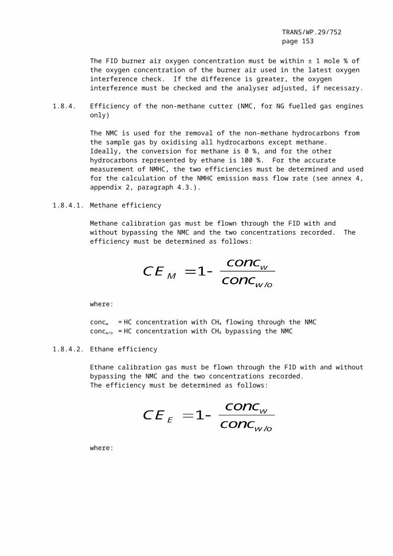
TRANS/WP.29/752page 153
PDP Positive displacement pump
The PDP meters total diluted exhaust flow from the number of the pump revolutions and the pump displacement. The exhaust system back-pressure must not be artificially lowered by the PDP or dilution air inlet system. Static exhaust back-pressure measured with the PDP system operating must remain within ± 1.5 kPa of the static pressure measured without connection to the PDP at identical engine speed and load. The gas mixture temperature immediately ahead of the PDP must be within ± 6 K of the average operating temperature observed during the test, when no flow compensation is used. Flow compensation may only be used if the temperature at the inlet to the PDP does not exceed 323K (50°C)
CFV Critical flow venturi
CFV measures total diluted exhaust flow by maintaining the flow at choked conditions (critical flow). Static exhaust back-pressure measured with the CFV system operating must remain within ± 1.5 kPa of the static pressure measured without connection to the CFV at identical engine speed and load. The gas mixture temperature immediately ahead of the CFV must be within ± 11 K of the average operating temperature observed during the test, when no flow compensation is used.
HE Heat exchanger (optional, if EFC is used)
The heat exchanger must be of sufficient capacity to maintain the temperature within the limits required above.
EFC Electronic flow compensation (optional, if HE is used)
If the temperature at the inlet to either the PDP or CFV is not kept within the limits stated above, a flow compensation system is required for continuous measurement of the flow rate and control of the proportional sampling in the particulate system. To that purpose, the continuously measured flow rate signals are used to correct the sample flow rate through the particulate filters of the particulate sampling system (see paragraph 2.4., figures 21, 22), accordingly.
DT Dilution tunnel
The dilution tunnel:
– must be small enough in diameter to cause turbulent flow (Reynolds Number greater than 4000) and of sufficient length to cause complete mixing of the exhaust and dilution air; a mixing orifice may be used;
– must be at least 460 mm in diameter with a single dilution system;

TRANS/WP.29/752page 154
– must be at least 210 mm in diameter with a double dilution system;
– may be insulated.
The engine exhaust must be directed downstream at the point where it is introduced into the dilution tunnel, and thoroughly mixed.
When using single dilution, a sample from the dilution tunnel is transferred to the particulate sampling system (paragraph 2.4., Figure 21). The flow capacity of the PDP or CFV must be sufficient to maintain the diluted exhaust at a temperature of less than or equal to 325 K (52°C) immediately before the primary particulate filter.
When using double dilution, a sample from the dilution tunnel is transferred to the secondary dilution tunnel where it is further diluted, and then passed through the sampling filters (paragraph 2.4., Figure 22). The flow capacity of the PDP or CFV must be sufficient to maintain the diluted exhaust stream in the DT at a temperature of less than or equal to 464 K (191°C) at the sampling zone. The secondary dilution system must provide sufficient secondary dilution air to maintain the doubly-diluted exhaust stream at a temperature of less than or equal to 325 K (52°C) immediately before the primary particulate filter.
DAF Dilution air filter
It is recommended that the dilution air be filtered and charcoal scrubbed to eliminate background hydrocarbons. At the engine manufacturers request the dilution air must be sampled according to good engineering practice to determine the background particulate levels, which can then be subtracted from the values measured in the diluted exhaust.
PSP Particulate sampling probe
The probe is the leading paragraph of PTT and:
must be installed facing upstream at a point where the dilution air and exhaust gas are well mixed, i.e. on the dilution tunnel (DT) centreline approximately 10 tunnel diameters downstream of the point where the exhaust enters the dilution tunnel;
must be of 12 mm minimum inside diameter;
may be heated to no greater than 325 K (52°C) wall temperature by direct heating or by dilution air pre-heating, provided the air temperature does not exceed 325 K (52°C) prior to the introduction of the exhaust in the dilution tunnel;
may be insulated.

TRANS/WP.29/752page 155
2.4. Particulate sampling system
The particulate sampling system is required for collecting the particulates on the particulate filter. In the case of total sampling partial flow dilution, which consists of passing the entire diluted exhaust sample through the filters, dilution (paragraph 2.2., figures 14, 18) and sampling system usually form an integral unit. In the case of fractional sampling partial flow dilution or full flow dilution, which consists of passing through the filters only a portion of the diluted exhaust, the dilution (paragraph 2.2., figures 11, 12, 13, 15, 16, 17, 19; paragraph 2.3., Figure 20) and sampling systems usually form different units.
In this Regulation, the double dilution system (Figure 22) of a full flow dilution system is considered as a specific modification of a typical particulate sampling system as shown in Figure 21. The double dilution system includes all important parts of the particulate sampling system, like filter holders and sampling pump, and additionally some dilution features, like a dilution air supply and a secondary dilution tunnel.
In order to avoid any impact on the control loops, it is recommended that the sample pump be running throughout the complete test procedure. For the single filter method, a bypass system must be used for passing the sample through the sampling filters at the desired times. Interference of the switching procedure on the control loops must be minimised.
FM3
FC3
FH
BV
optional
from EGA
from PDP
from CFV
from GFUEL
or
or
or
PTT
P
from dilution tunnel DTsee figures 11 to 20
Figure 21 - Particulate sampling system

TRANS/WP.29/752page 156
A sample of the diluted exhaust gas is taken from the dilution tunnel DT of a partial flow or full flow dilution system through the particulate sampling probe PSP and the particulate transfer tube PTT by means of the sampling pump P. The sample is passed through the filter holder(s) FH that contain the particulate sampling filters. The sample flow rate is controlled by the flow controller FC3. If electronic flow compensation EFC (see Figure 20) is used, the diluted exhaust gas flow is used as command signal for FC3.
FM4 DPSDT BV
FH FM3
BV optional
PTT
P
FC3PDPorCFV
from dilutiontunnel DTsee figure 20
vent
Figure 22 - Double dilution system (full flow system only)
A sample of the diluted exhaust gas is transferred from the dilution tunnel DT of a full flow dilution system through the particulate sampling probe PSP and the particulate transfer tube PTT to the secondary dilution tunnel SDT, where it is diluted once more. The sample is then passed through the filter holder(s) FH that contain the particulate sampling filters. The dilution air flow rate is usually constant whereas the sample flow rate is controlled by the flow controller FC3. If electronic flow compensation EFC (see Figure 20) is used, the total diluted exhaust gas flow is used as command signal for FC3.
2.4.1. Components of figures 21 and 22
PTT Particulate transfer tube (Figures 21, 22)
The particulate transfer tube must not exceed 1020 mm in length, and must be minimised in length whenever possible. Where applicable (i.e. for partial flow dilution fractional sampling systems and for full flow dilution systems), the length of the sampling probes (SP, ISP, PSP, respectively, see paragraphs 2.2. and 2.3.) must be included.
The dimensions are valid for:
the partial flow dilution fractional sampling type and the full flow single dilution system from the tip of the probe (SP, ISP, PSP, respectively) to the filter holder;
the partial flow dilution total sampling type from the end of the dilution tunnel to the filter holder;

TRANS/WP.29/752page 157
the full flow double dilution system from the tip of the probe (PSP) to the secondary dilution tunnel.
The transfer tube:
may be heated to no greater than 325K (52°C) wall temperature by direct heating or by dilution air pre- heating, provided the air temperature does not exceed 325 K (52°C) prior to the introduction of the exhaust in the dilution tunnel;
may be insulated.
SDT Secondary dilution tunnel (Figure 22)
The secondary dilution tunnel should have a minimum diameter of 75 mm, and should be of sufficient length so as to provide a residence time of at least 0.25 seconds for the doubly-diluted sample. The primary filter holder FH must be located within 300 mm of the exit of the SDT.
The secondary dilution tunnel:
may be heated to no greater than 325 K (52°C) wall temperature by direct heating or by dilution air pre-heating, provided the air temperature does not exceed 325 K (52°C) prior to the introduction of the exhaust in the dilution tunnel;
may be insulated.
FH Filter holder(s) (Figures 21, 22)
For primary and back-up filters one filter housing or separate filter housings may be used. The requirements of annex 4, appendix 4, paragraph 4.1.3. must be met.
The filter holder(s):
may be heated to no greater than 325 K (52°C) wall temperature by direct heating or by dilution air pre-heating, provided the air temperature does not exceed 325 K (52°C) prior to the introduction of the exhaust in the dilution tunnel;
may be insulated.
P Sampling pump (Figures 21, 22)
The particulate sampling pump must be located sufficiently distant from the tunnel so that the inlet gas temperature is maintained constant (± 3 K), if flow correction by FC3 is not used.

TRANS/WP.29/752page 158
DP Dilution air pump (Figure 22)
The dilution air pump must be located so that the secondary dilution air is supplied at a temperature of 298 K ± 5 K (25°C ± 5°C), if the dilution air is not preheated.
FC3 Flow controller (Figures 21, 22)
A flow controller must be used to compensate the particulate sample flow rate for temperature and back pressure variations in the sample path, if no other means are available. The flow controller is required if electronic flow compensation EFC (see Figure 20) is used.
FM3 Flow measurement device (Figures 21, 22)
The gas meter or flow instrumentation for the particulate sample flow must be located sufficiently distant from the sampling pump P so that the inlet gas temperature remains constant (± 3 K), if flow correction by FC3 is not used.
FM4 Flow measurement device (Figure 22)
The gas meter or flow instrumentation for the dilution air flow must be located so that the inlet gas temperature remains at 298 K ± 5 K (25°C ± 5°C).
BV Ball valve (optional)
The ball valve must have an inside diameter not less than the inside diameter of the particulate transfer tube PTT, and a switching time of less than 0.5 seconds.
Note: If the ambient temperature in the vicinity of PSP, PTT, SDT, and FH is below 293K (20°C), precautions should be taken to avoid particle losses onto the cool wall of these parts. Therefore, heating and/or insulating these parts within the limits given in the respective descriptions is recommended. It is also recommended that the filter face temperature during sampling be not below 293K (20°C).
At high engine loads, the above parts may be cooled by a non-aggressive means such as a circulating fan, as long as the temperature of the cooling medium is not below 293K (20°C).
3. DETERMINATION OF SMOKE OPACITY
3.1. Introduction
Paragraphs 3.2. and 3.3. and figures 23 and 24 contain detailed descriptions of the recommended opacimeter systems. Since various configurations can produce equivalent results, exact conformance with figures 23 and 24 is not required. Additional components such as instruments, valves, solenoids, pumps, and switches may be used to provide additional information and coordinate the functions of the component systems. Other components, which are not needed to

TRANS/WP.29/752page 159
maintain the accuracy on some systems, may be excluded if their exclusion is based upon good engineering judgement.
The principle of measurement is that light is transmitted through a specific length of the smoke to be measured and that proportion of the incident light which reaches a receiver is used to assess the light obscuration properties of the medium. The smoke measurement depends upon the design of the apparatus, and may be done in the exhaust pipe (full flow in-line opacimeter), at the end of the exhaust pipe (full flow end-of-line opacimeter) or by taking a sample from the exhaust pipe (partial flow opacimeter). For the determination of the light absorption coefficient from the opacity signal, the optical path length of the instrument must be supplied by the instrument manufacturer.
3.2. Full Flow Opacimeter
Two general types of full flow opacimeters may be used (Figure 23). With the in-line opacimeter, the opacity of the full exhaust plume within the exhaust pipe is measured. With this type of opacimeter, the effective optical path length is a function of the opacimeter design.
With the end-of-line opacimeter, the opacity of the full exhaust plume is measured as it exits the exhaust pipe. With this type of opacimeter, the effective optical path length is a function of the exhaust pipe design and the distance between the end of the exhaust pipe and the opacimeter.
EP
OPL
T1 (optional)
CL
LDLS
CL
Figure 23 - Full flow opacimeter
TRANS/WP.29/752page 160
3.2.1. Components of Figure 23
EP Exhaust Pipe
With an in-line opacimeter, there must be no change in the exhaust pipe diameter within 3 exhaust pipe diameters before or after the measuring zone. If the diameter of the measuring zone is greater than the diameter of the exhaust pipe, a pipe gradually convergent before the measuring zone is recommended.
With an end-of-line opacimeter, the terminal 0.6 m of the exhaust pipe must be of circular cross paragraph and be free from elbows and bends. The end of the exhaust pipe must be cut off squarely. The opacimeter must be mounted centrally to the plume within 25 5 mm of the end of the exhaust pipe.
OPL Optical Path Length
The length of the smoke obscured optical path between the opacimeter light source and the receiver, corrected as necessary for non-uniformity due to density gradients and fringe effect. The optical path length must be submitted by the instrument manufacturer taking into account any measures against sooting (e.g. purge air). If the optical path length is not available, it must be determined in accordance with ISO IDS 11614, paragraph 11.6.5. For the correct determination of the optical path length, a minimum exhaust gas velocity of 20 m/s is required.
LS Light source
The light source must be an incandescent lamp with a colour temperature in the range of 2800 to 3250 K or a green light emitting diode (LED) with a spectral peak between 550 and 570 nm. The light source must be protected against sooting by means that do not influence the optical path length beyond the manufacturers specifications.
LD Light detector
The detector must be a photocell or a photodiode (with a filter, if necessary). In the case of an incandescent light source, the receiver must have a peak spectral response similar to the phototopic curve of the human eye (maximum response) in the range of 550 to 570 nm, to less than 4 per cent of that maximum response below 430 nm and above 680 nm. The light detector must be protected against sooting by means that do not influence the optical path length beyond the manufacturers specifications.

TRANS/WP.29/752page 161
CL Collimating lens
The light output must be collimated to a beam with a maximum diameter of 30 mm. The rays of the light beam must be parallel within a tolerance of 3° of the optical axis.
T1 Temperature sensor (optional)
The exhaust gas temperature may be monitored over the test.
3.3. Partial Flow Opacimeter
With the partial flow opacimeter (Figure 24), a representative exhaust sample is taken from the exhaust pipe and passed through a transfer line to the measuring chamber. With this type of opacimeter, the effective optical path length is a function of the opacimeter design. The response times referred to in the following paragraph apply to the minimum flow rate of the opacimeter, as specified by the instrument manufacturer.
Exhaust
EP
SP
TT
T1FM
P (optional)
OPL
MC
CL
LS
CL
LD
Figure 24 - Partial flow opacimeter
3.3.1. Components of figure 24
EP Exhaust pipe
The exhaust pipe must be a straight pipe of at least 6 pipe diameters upstream and 3 pipe diameters downstream of the tip of the probe.

TRANS/WP.29/752page 162
SP Sampling probe
The sampling probe must be an open tube facing upstream on or about the exhaust pipe centreline. The clearance with the wall of the tailpipe must be at least 5 mm. The probe diameter must ensure a representative sampling and a sufficient flow through the opacimeter.
TT Transfer tube
The transfer tube must:
Be as short as possible and ensure an exhaust gas temperature of 373 30 K (100°C 30°C) at the entrance to the measuring chamber.
Have a wall temperature sufficiently above the dew point of the exhaust gas to prevent condensation.
Be equal to the diameter of the sampling probe over the entire length.
Have a response time of less than 0.05 s at minimum instrument flow, as determined according to annex 4, appendix 4, paragraph 5.2.4.
Have no significant effect on the smoke peak.
FM Flow measurement device
Flow instrumentation to detect the correct flow into the measuring chamber. The minimum and maximum flow rates must be specified by the instrument manufacturer, and must be such that the response time requirement of TT and the optical path length specifications are met. The flow measurement device may be close to the sampling pump, P, if used.
MC Measuring chamber
The measuring chamber must have a non-reflective internal surface, or equivalent optical environment. The impingement of stray light on the detector due to internal reflections of diffusion effects must be reduced to a minimum.
The pressure of the gas in the measuring chamber must not differ from the atmospheric pressure by more than 0.75 kPa. Where this is not possible by design, the opacimeter reading must be converted to atmospheric pressure.
The wall temperature of the measuring chamber must be set to within 5 K between 343 K (70°C) and 373 K (100°C), but in any case sufficiently above the dew point of the exhaust gas to prevent condensation. The measuring chamber must be equipped with appropriate devices for measuring the temperature.
OPL Optical path length

TRANS/WP.29/752page 163
The length of the smoke obscured optical path between the opacimeter light source and the receiver, corrected as necessary for non-uniformity due to density gradients and fringe effect. The optical path length must be submitted by the instrument manufacturer taking into account any measures against sooting (e.g. purge air). If the optical path length is not available, it must be determined in accordance with ISO IDS 11614, paragraph 11.6.5.
LS Light source
The light source must be an incandescent lamp with a colour temperature in the range of 2800 to 3250 K or a green light emitting diode (LED) with a spectral peak between 550 and 570 nm. The light source must be protected against sooting by means that do not influence the optical path length beyond the manufacturers specifications.
LD Light detector
The detector must be a photocell or a photodiode (with a filter, if necessary). In the case of an incandescent light source, the receiver must have a peak spectral response similar to the phototopic curve of the human eye (maximum response) in the range of 550 to 570 nm, to less than 4 per cent of that maximum response below 430 nm and above 680 nm. The light detector must be protected against sooting by means that do not influence the optical path length beyond the manufacturers specifications.
CL Collimating lens
The light output must be collimated to a beam with a maximum diameter of 30 mm. The rays of the light beam must be parallel within a tolerance of 3° of the optical axis.
T1 Temperature sensor
To monitor the exhaust gas temperature at the entrance to the measuring chamber.
P Sampling pump (optional)
A sampling pump downstream of the measuring chamber may be used to transfer the sample gas through the measuring chamber.

TRANS/WP.29/752page 164
Annex 5, amend to read:
"Annex 5
TECHNICAL CHARACTERISTICS OF REFERENCE FUEL FOR C.I. ENGINES PRESCRIBED FOR APPROVAL TESTS AND TO VERIFY CONFORMITY OF PRODUCTION
1. DIESEL FUEL (1)
Parameter Unit Limits (1) Test Method (2) Publication
Minimum MaximumCetane number (3) 52 54 ISO 5165 1998 (4)
Density at 15 °C kg/m3 833 837 ISO 3675 1995Distillation :- 50 % point °C 245 ISO 3405 1998- 95 % point °C 345 350 ISO 3405 1998- final boiling point
°C --- 370 ISO 3405 1998
Flash point °C 55 --- EN 27719 1993CFPP °C --- -5 EN 116 1981Viscosity at 40 °C mm²/s 2.5 3.5 EN-ISO 3104 1996Polycyclic aromatic hydrocarbons
% m/m 3.0 6.0 IP 391 (*) 1995
Sulphur content(5)
mg/kg --- 300 pr. EN-ISO/DIS 14596 1998 (4)
Copper corrosion --- 1 EN-ISO 2160 1995Conradson carbon residue (10 % DR)
% m/m --- 0.2 EN-ISO 10370
Ash content % m/m --- 0.01 EN-ISO 6245 1995Water content % m/m --- 0.05 EN-ISO 12937 1995Neutralisation (strong acid) number
mg OH/g --- 0.02 ASTM D 974-95 1998 (4)
Oxidation stability (6)
mg/ ml --- 0.025 EN-ISO 12205 1996
(1) If it is required to calculate the thermal efficiency of an engine or vehicle, the calorific value of the fuel can be calculated from:Specific energy (calorific value) (net) in MJ/kg = (46.423 - 8.792d²
+ 3.170d) (1 - (x + y + s)) + 9.420s - 2.499x
where:
d = the density at 15 °C x = the proportion by mass of water (% divided by 100)y = the proportion by mass of ash (% divided by 100)s = the proportion by mass of sulphur (% divided by 100).
(2) The values quoted in the specification are "true values". In establishment of their limit values the terms of ISO 4259, Petroleum products - Determination and application of precision data in relation to methods of test, have been applied and in fixing a
TRANS/WP.29/752page 165
minimum value, a minimum difference of 2R above zero has been taken into account; in fixing a maximum and minimum value, the minimum difference is 4R (R - reproducibility). Notwithstanding this measure, which is necessary for statistical reasons, the manufacturer of a fuel should nevertheless aim at a zero value where the stipulated maximum value is 2R and at the mean value in the case of quotations of maximum and minimum limits. Should it be necessary to clarify the question as to whether a fuel meets the requirements of the specification, the terms of ISO 4259 should be applied.
(3) The range for cetane number is not in accordance with the requirement of a minimum range of 4R. However, in the case of dispute between fuel supplier and fuel user, the terms in ISO 4259 can be used to resolve such disputes provided replicate measurements, of sufficient number to achieve the necessary precision, are made in preference to single determinations.
(4) The month of publication will be completed in due course.
(5) The actual sulphur content of the fuel used for the test must be reported. In addition, the sulphur content of the reference fuel used to approve a vehicle or engine against the limit values set out in row B of the Table in paragraph 5.2.1. of this Regulation must have a maximum sulphur content of 50 ppm.
(6) Even though oxidation stability is controlled, it is likely that shelf life will be limited. Advice should be sought from the supplier as to storage conditions and life.
__________"
TRANS/WP.29/752page 166
Annex 6, amend to read:
"Annex 6
TECHNICAL CHARACTERISTICS OF REFERENCE N.G. FUEL PRESCRIBED FOR APPROVAL TESTS AND TO VERIFY CONFORMITY OF PRODUCTION
Type: NATURAL GAS (NG)
European market fuels are available in two ranges:
– the H range, whose extreme reference fuels are G20 and G23;– the L range, whose extreme reference fuels are G23 and G25.
The characteristics of G20, G23 and G25 reference fuels are summarised below:
Reference fuel G20
Characteristics Units Basis Limits Test MethodMin. Max.
Composition:Methane 100 99 100Balance %mole - - 1 ISO 6974[Inerts +C2/C2+ ]N2
Sulphur content mg/m3 - - 50 ISO 6326-5
Reference fuel G23
Characteristics Units Basis Limits Test MethodMin. Max.
Composition:Methane 92.5 91.5 93.5Balance %mole - - 1 ISO 6974[Inerts +C2/C2+ ]N2 7.5 6.5 8.5Sulphur content mg/m3 (*) - - 50 ISO 6326-5
(*) value to be determined at standard conditions (293.2 K (20°C) and 101.3 kPa).

TRANS/WP.29/752page 167
Reference fuel G25
Characteristics Units Basis Limits Test MethodMin. Max.
Composition:Methane 86 84 88Balance %mole - - 1 ISO 6974[Inerts +C2/C2+ ]N2 14 12 16Sulphur content mg/m3 (*) - - 50 ISO 6326-5
(*)value to be determined at standard conditions (293.2 K (20°C) and 101.3 kPa).
__________"
Insert new Annexes 7 and 8, to read:
"Annex 7
Type: LIQUEFIED PETROLEUM GAS (LPG)
Parameter Unit Limits Fuel A Limits Fuel B Test MethodMinimum Maximum Minimum Maximum
Motor Octane Number 93.5 93.5EN 589 Annex B
Composition:C3 content % vol 48 52 83 87C4 content % vol 48 52 13 17 ISO 7941Olefins % vol 0 12 9 15Evaporation Residue mg/kg 50 50 NFM 41-015Total sulphur content ppm 50 50 EN 24260Hydrogen sulphide --- None None ISO 8819Copper strip corrosion rating class 1 class 1 ISO 6251(2)
Water at 0°C free freevisual
inspection
(1) Value to be determined at standard conditions 293.2 K (20 °C) and 101.3 kPa
(2)This method may not accurately determine the presence of corrosive materials if the sample contains corrosion inhibitors or other chemicals, which diminish the corrosivity of the sample to the copper strip. Therefore, the addition of such compounds for the sole purpose of biasing the test method is prohibited.
__________
TRANS/WP.29/752page 168
Annex 8
EXAMPLE OF CALCULATION PROCEDURE
1. ESC TEST
1.1. Gaseous emissions
The measurement data for the calculation of the individual mode results are shown below. In this example, CO and NOx are measured on a dry basis, HC on a wet basis. The HC concentration is given in propane equivalent (C3) and has to be multiplied by 3 to result in the C1 equivalent. The calculation procedure is identical for the other modes.
P(kW)
Ta
(K)Ha
(g/kg)GEXH
(kg)GAIRW
(kg)GFUEL
(kg)HC
(ppm)CO
(ppm)NOx
(ppm)82.9 294.8 7.81 563.38 545.29 18.09 6.3 41.2 495
Calculation of the dry to wet correction factor KW,r (annex 4, appendix 1, paragraph 4.2.):
FFH = = 1.9058 and KW2 = = 0.0124
KW,r =
Calculation of the wet concentrations:
CO = 41.2 * 0.9239 = 38.1 ppmNOx = 495 * 0.9239= 457 ppm
Calculation of the NOx humidity correction factor KH,D (annex 4, appendix 1, paragraph 4.3.):
A = 0.309 * 18.09/541.06 - 0.0266 = -0.0163B = -0.209 * 18.09/541.06 + 0.00954 = 0.0026
Calculation of the emission mass flow rates (annex 4, appendix 1, paragraph 4.4.):
NOx = 0.001587 * 457 * 0.9625 * 563.38 = 393.27 g/hCO = 0.000966 * 38.1 * 563.38 = 20.735 g/hHC = 0.000479 * 6.3 * 3 * 563.38 = 5.100 g/h

TRANS/WP.29/752page 169
Calculation of the specific emissions (annex 4, appendix 1, paragraph 4.5.):
The following example calculation is given for CO; the calculation procedure is identical for the other components.
The emission mass flow rates of the individual modes are multiplied by the respective weighting factors, as indicated in annex 4, appendix 1, paragraph 2.7.1., and summed up to result in the mean emission mass flow rate over the cycle:
CO = (6.7 * 0.15) + (24.6 * 0.08) + (20.5 * 0.10) + (20.7 * 0.10) + (20.6 * 0.05) + (15.0 * 0.05) + (19.7 * 0.05) + (74.5 * 0.09) + (31.5 * 0.10) + (81.9 * 0.08) + (34.8 * 0.05) + (30.8 * 0.05) + (27.3 * 0.05) = 30.91 g/h
The engine power of the individual modes is multiplied by the respective weighting factors, as indicated in annex 4, appendix 1, paragraph 2.7.1., and summed up to result in the mean cycle power:
P(n) = (0.1 * 0.15) + (96.8 * 0.08) + (55.2 * 0.10) + (82.9 * 0.10) + (46.8 * 0.05) + (70.1 * 0.05) + (23.0 * 0.05) +(114.3 * 0.09) + (27.0 * 0.10) + (122.0 * 0.08) + (28.6 * 0.05) + (87.4 * 0.05) + (57.9 * 0.05) = 60.006 kW
= 0.515 g/kWh
Calculation of the specific NOx emission of the random point (annex 4, appendix 1, paragraph 4.6.1.):
Assume the following values have been determined on the random point:
nZ = 1600 min-1
MZ = 495 NmNOx mass,Z = 487.9 g/h (calculated according to the previous
formulae)P(n)Z = 83 kWNOx,Z = 487.9/83 = 5.878 g/kWh
Determination of the emission value from the test cycle (annex 4, appendix 1, paragraph 4.6.2.):
Assume the values of the four enveloping modes on the ESC to be as follows:
nRT nSU ER ES ET EU MR MS MT MU
1368 1785 5.943 5.565 5.889 4.973 515 460 681 610
ETU = 5.889 + (4.973-5.889) * (1600-1368)/(1785-1368) = 5.377 g/kWhERS = 5.943 + (5.565-5.943) * (1600-1368)/(1785-1368) = 5.732 g/kWhMTU = 681 + (601-681) * (1600-1368)/(1785-1368) = 641.3 Nm

TRANS/WP.29/752page 170
MRS = 515 + (460-515) * (1600-1368)/(1785-1368) = 484.3 Nm
EZ = 5.732 + (5.377-5.732) * (495-484.3)/(641.3-484.3) = 5.708 g/kWh
Comparison of the NOx emission values (annex 4, appendix 1, paragraph 4.6.3.):
NOx diff = 100 * (5.878-5.708)/5.708 = 2.98 %
1.2. Particulate Emissions
Particulate measurement is based on the principle of sampling the particulates over the complete cycle, but determining the sample and flow rates (MSAM and GEDF) during the individual modes. The calculation of GEDF depends on the system used. In the following examples, a system with CO2 measurement and carbon balance method and a system with flow measurement are used. When using a full flow dilution system, GEDF is directly measured by the CVS equipment.
Calculation of GEDF (annex 4, appendix 1, paragraphs 5.2.3. and 5.2.4.):
Assume the following measurement data of mode 4. The calculation procedure is identical for the other modes.
GEXH
(kg/h)GFUEL
(kg/h)GDILW
(kg/h)GTOTW
(kg/h)CO2D
(%)CO2A
(%)334.02 10.76 5.4435 6.0 0.657 0.040
a) carbon balance method
GEDFW = = 3601.2 kg/h
b) flow measurement method
q = = 10.78
GEDFW = 334.02 * 10.78 = 3600.7 kg/h
Calculation of the mass flow rate (annex 4, appendix 1, paragraph 5.4.):
The GEDFW flow rates of the individual modes are multiplied by the respective weighting factors, as indicated in annex 4, appendix 1, paragraph 2.7.1., and summed up to result in the mean GEDF over the cycle. The total sample rate MSAM is summed up from the sample rates of the individual modes.

TRANS/WP.29/752page 171
= (3567 * 0.15)+(3592 * 0.08)+(3611 *
0.10)+(3600 * 0.10) +(3618 * 0.05) +(3600 * 0.05)+(3640 * 0.05)+(3614 * 0.09)+(3620 * 0.10)+(3601 * 0.08) +(3639 * 0.05)+(3582 * 0.05)+(3635 * 0.05)= 3604.6 kg/h
MSAM = 0.226 + 0.122 + 0.151 + 0.152 + 0.076 + 0.076 + 0.076 + 0.136 + 0.151 + 0.121 + 0.076 + 0.076 + 0.075 = 1.515 kg
Assume the particulate mass on the filters to be 2.5 mg, then
PTmass = = 5.948 g/h
Background correction (optional)
Assume one background measurement with the following values. The calculation of the dilution factor DF is identical to paragraph 3.1. of this annex and not shown here.
Md = 0.1 mg; MDIL = 1.5 kg
Sum of DF = [(1-1/119.15) * 0.15] + [(1-1/8.89) * 0.08] + [(1-1/14.75) * 0.10] + [(1-1/10.10) * 0.10] + [(1-1/18.02) * 0.05] + [(1-1/12.33) * 0.05] + [(1-1/32.18) * 0.05] + [(1-1/6.94) * 0.09] + [(1-1/25.19) * 0.10] + [(1-1/6.12) * 0.08] + [(1-1/20.87) * 0.05] + [(1-1/8.77) * 0.05] + [(1-1/12.59) * 0.05] = 0.923
PTmass = = 5.726 g/h
Calculation of the specific emission (annex 4, appendix 1, paragraph 5.5.):
P(n) = (0.1 * 0.15) + (96.8 * 0.08) + (55.2 * 0.10) +(82.9 * 0.10) +(46.8 * 0.05) +(70.1 * 0.05) + (23.0 * 0.05) +(114.3 * 0.09) + (27.0 * 0.10) +(122.0 * 0.08) + (28.6 * 0.05) + (87.4 * 0.05) + (57.9 * 0.05) = 60.006 kW
= 0.099 g/kWh, if background corrected
= 0.095 g/kWh
Calculation of the specific weighting factor (annex 4, appendix 1, paragraph 5.6.):
Assume the values calculated for mode 4 above, then
WFE,I = = 0.1004
This value is within the required value of 0.10 ± 0.003.

TRANS/WP.29/752page 172
2 ELR TEST
Since Bessel filtering is a completely new averaging procedure in European exhaust legislation, an explanation of the Bessel filter, an example of the design of a Bessel algorithm, and an example of the calculation of the final smoke value is given below. The constants of the Bessel algorithm only depend on the design of the opacimeter and the sampling rate of the data acquisition system. It is recommended that the opacimeter manufacturer provide the final Bessel filter constants for different sampling rates and that the customer use these constants for designing the Bessel algorithm and for calculating the smoke values.
2.1. General remarks on the Bessel filter
Due to high frequency distortions, the raw opacity signal usually shows a highly scattered trace. To remove these high frequency distortions a Bessel filter is required for the ELR-Test. The Bessel filter itself is a recursive, second-order low-pass filter which guarantees the fastest signal rise without overshoot.
Assuming a real time raw exhaust plume in the exhaust tube, each opacimeter shows a delayed and differently measured opacity trace. The delay and the magnitude of the measured opacity trace is primarily dependent on the geometry of the measuring chamber of the opacimeter, including the exhaust sample lines, and on the time needed for processing the signal in the electronics of the opacimeter. The values that characterise these two effects are called the physical and the electrical response time which represent an individual filter for each type of opacimeter. The goal of applying a Bessel filter is to guarantee a uniform overall filter characteristic of the whole opacimeter system, consisting of:
- physical response time of the opacimeter (tp)- electrical response time of the opacimeter (te)- filter response time of the applied Bessel filter (tF)
The resulting overall response time of the system tAver is given by:
tAver =
and must be equal for all kinds of opacimeters in order to give the same smoke value. Therefore, a Bessel filter has to be created in such a way, that the filter response time (tF) together with the physical (tp) and electrical response time (te) of the individual opacimeter must result in the required overall response time (tAver). Since tp and te are given values for each individual opacimeter, and tAver is defined to be 1.0 s in this Regulation, tF can be calculated as follows:
tF =

TRANS/WP.29/752page 173
By definition, the filter response time tF is the rise time of a filtered output signal between 10 % and 90 % on a step input signal. Therefore the cut-off frequency of the Bessel filter has to be iterated in such a way, that the response time of the Bessel filter fits into the required rise time.
Figure (a) - Traces of a Step Input Signal and the Filtered Output Signal
In figure (a), the traces of a step input signal and Bessel filtered output signal as well as the response time of the Bessel filter (tF) are shown.
Designing the final Bessel filter algorithm is a multi step process which requires several iteration cycles. The scheme of the iteration procedure is presented below.
Sig
nal [
-]

TRANS/WP.29/752page 174

TRANS/WP.29/752page 175
2.2. Calculation of the Bessel algorithm
In this example a Bessel algorithm is designed in several steps according to the above iteration procedure which is based upon annex 4, appendix 1, paragraph 6.1.
For the opacimeter and the data acquisition system, the following characteristics are assumed:
- physical response time tp 0.15 s- electrical response time te 0.05 s- overall response time tAver 1.00 s (by definition in this Regulation)- sampling rate 150 Hz
Step 1 Required Bessel filter response time tF:
tF = = 0.987421 s
Step 2 Estimation of cut-off frequency and calculation of Bessel constants E, K for first iteration:
fc = 3.1415 / (10 * 0.987421) = 0.318152 HzΔt = 1 / 150 = 0.006667 sΩ = 1 / [tan (3.1415 * 0.006667 * 0.318152)] = 150.076644
E = = 7.07948 E-5
K = 2 * 7.07948 E-5 * (0.618034 * 150.076644 - 1) – 1 = 0.970783
This gives the Bessel algorithm:
Yi = Yi-1 + 7.07948 E-5 * (Si + 2 * Si-1 + Si-2 - 4 * Yi-2) + 0.970783 * (Yi-1 - Yi-2)
where Si represents the values of the step input signal (either '0' or '1') and Yi represents the filtered values of the output signal.
Step 3 Application of Bessel filter on step input:
The Bessel filter response time tF is defined as the rise time of the filtered output signal between 10 % and 90 % on a step input signal. For determining the times of 10 % (t10) and 90 % (t90) of the output signal, a Bessel filter has to be applied to a step input using the above values of fc, E and K.
The index numbers, the time and the values of a step input signal and the resulting values of the filtered output signal for the first and the second iteration are shown in table B. The points adjacent to t10 and t90 are marked in bold numbers.
TRANS/WP.29/752page 176
In table B, first iteration, the 10 % value occurs between index number 30 and 31 and the 90 % value occurs between index number 191 and 192. For the calculation of tF,iter the exact t10 and t90 values are determined by linear interpolation between the adjacent measuring points, as follows:
t10=tlower + Δt * (0.1-outlower)/(outupper - outlower)
t90=tlower + Δt * (0.9-outlower)/(outupper - outlower)
where outupper and outlower, respectively, are the adjacent points of the Bessel filtered output signal, and tlower is the time of the adjacent time point, as indicated in table B.
t10=0.200000+0.006667*(0.1-0.099208)/(0.104794-0.099208)=0.200945 s
t90=1.273333+0.006667*(0.9-0.899147)/(0.901168-0.899147)=1.276147 s
Step 4 Filter response time of first iteration cycle:
tF,iter = 1.276147 - 0.200945 = 1.075202 s
Step 5 Deviation between required and obtained filter response time of first iteration cycle:
Δ = (1.075202 - 0.987421) / 0.987421 = 0.081641
Step 6 Checking the iteration criteria:
|Δ| ≤ 0.01 is required. Since 0.081641 > 0.01, the iteration criteria is not met and a further iteration cycle has to be started. For this iteration cycle, a new cut-off frequency is calculated from fc and Δ as follows:
fc,new = 0.318152 * (1 + 0.081641) = 0.344126 Hz
This new cut-off frequency is used in the second iteration cycle, starting at step 2 again. The iteration has to be repeated until the iteration criteria is met. The resulting values of the first and second iteration are summarised in table A.
Parameter 1. Iteration 2. Iteration
fc (Hz) 0.318152 0.344126E (-) 7.07948 E-5 8.272777 E-5K (-) 0.970783 0.968410t10 (s) 0.200945 0.185523t90 (s) 1.276147 1.179562tF,iter (s) 1.075202 0.994039Δ (-) 0.081641 0.006657fc,new (Hz) 0.344126 0.346417
Table A - Values of the first and second iteration

TRANS/WP.29/752page 177
Step 7 Final Bessel algorithm:
As soon as the iteration criteria has been met, the final Bessel filter constants and the final Bessel algorithm are calculated according to step 2. In this example, the iteration criteria has been met after the second iteration (Δ = 0.006657 ≤ 0.01). The final algorithm is then used for determining the averaged smoke values (see next paragraph 2.3).
YI=Yi-1+8.272777E-5*(Si+2*Si-1+Si-2-4*Yi-2)+0.968410*(Yi-1-Yi-2)

TRANS/WP.29/752page 178
Step Input Filtered Output SignalSignal Yi
Index i Time Si [-][-] [s] [-] 1. Iteration 2. Iteration-2 -0.013333 0 0.000000 0.000000-1 -0.006667 0 0.000000 0.0000000 0.000000 1 0.000071 0.0000831 0.006667 1 0.000352 0.0004112 0.013333 1 0.000908 0.0010603 0.020000 1 0.001731 0.0020194 0.026667 1 0.002813 0.0032785 0.033333 1 0.004145 0.004828~ ~ ~ ~ ~24 0.160000 1 0.067877 0.07787625 0.166667 1 0.072816 0.08347626 0.173333 1 0.077874 0.08920527 0.180000 1 0.083047 0.09505628 0.186667 1 0.088331 0.10102429 0.193333 1 0.093719 0.10710230 0.200000 1 0.099208 0.11328631 0.206667 1 0.104794 0.11957032 0.213333 1 0.110471 0.12594933 0.220000 1 0.116236 0.13241834 0.226667 1 0.122085 0.13897235 0.233333 1 0.128013 0.14560536 0.240000 1 0.134016 0.15231437 0.246667 1 0.140091 0.159094~ ~ ~ ~ ~175 1.166667 1 0.862416 0.895701176 1.173333 1 0.864968 0.897941177 1.180000 1 0.867484 0.900145178 1.186667 1 0.869964 0.902312179 1.193333 1 0.872410 0.904445180 1.200000 1 0.874821 0.906542181 1.206667 1 0.877197 0.908605182 1.213333 1 0.879540 0.910633183 1.220000 1 0.881849 0.912628184 1.226667 1 0.884125 0.914589185 1.233333 1 0.886367 0.916517186 1.240000 1 0.888577 0.918412187 1.246667 1 0.890755 0.920276188 1.253333 1 0.892900 0.922107189 1.260000 1 0.895014 0.923907190 1.266667 1 0.897096 0.925676191 1.273333 1 0.899147 0.927414192 1.280000 1 0.901168 0.929121193 1.286667 1 0.903158 0.930799194 1.293333 1 0.905117 0.932448195 1.300000 1 0.907047 0.934067~ ~ ~ ~ ~
Table B - Values of step input signal and Bessel filtered output signal for the first and second iteration cycle

TRANS/WP.29/752page 179
2.3. Calculation of the Smoke Values
In the scheme below the general procedure of determining the final smoke value is presented.

TRANS/WP.29/752page 180
In figure b, the traces of the measured raw opacity signal, and of the unfiltered and filtered light absorption coefficients (k-value) of the first load step of an ELR-Test are shown, and the maximum value Ymax1,A (peak) of the filtered k trace is indicated. Correspondingly, table C contains the numerical values of index i, time (sampling rate of 150 Hz), raw opacity, unfiltered k and filtered k. Filtering was conducted using the constants of the Bessel algorithm designed in paragraph 2.2. of this annex. Due to the large amount of data, only those sections of the smoke trace around the beginning and the peak are tabled.
Figure b - Traces of measured opacity N, of unfiltered smoke k and of filtered smoke k
The peak value (i = 272) is calculated assuming the following data of table C. All other individual smoke
Calculation of the k-value (annex 4, appendix 1, paragraph 6.3.1.):
LA (m) 0.430Index I 272N (%) 16.783
S271 (m-1) 0.427392S270 (m-1) 0.427532Y271 (m-1) 0.542383Y270 (m-1) 0.542337
Opa
city
N [%
]

TRANS/WP.29/752page 181
k = - = 0.427252 m-1
This value corresponds to S272 in the equation that follows.
Calculation of Bessel averaged smoke (annex 4, appendix 1, paragraph 6.3.2.):
In the following equation, the Bessel constants of the previous paragraph 2.2. are used. The actual unfiltered k-value, as calculated above, corresponds to S272 (Si). S271 (Si-1) and S270 (Si-2) are the two preceding unfiltered k-values, Y271 (Yi-1) and Y270 (Yi-2) are the two preceding filtered k-values.
Y272 = 0.542383+8.272777E-5*(0.427252+2*0.427392+0.427532-4*0.542337)+ 0.968410*(0.542383-0.542337) = 0.542389 m-1
This value corresponds to Ymax1,A in the following equation.
Calculation of the final smoke value (annex 4, appendix 1, paragraph 6.3.3.):
From each smoke trace, the maximum filtered k-value is taken for the further calculation. Assume the following values:
Ymax (m-1)Speed Cycle 1 Cycle 2 Cycle 3
A 0.5424 0.5435 0.5587
B 0.5596 0.5400 0.5389
C 0.4912 0.5207 0.5177
SVA = (0.5424 + 0.5435 + 0.5587) / 3 = 0.5482 m-1
SVB = (0.5596 + 0.5400 + 0.5389) / 3 = 0.5462 m-1
SVC = (0.4912 + 0.5207 + 0.5177) / 3 = 0.5099 m-1
SV = (0.43*0.5482)+(0.56*0.5462)+(0.01*0.5099) = 0.5467 m-1

TRANS/WP.29/752page 182
Cycle validation (annex 4, appendix 1, paragraph 3.4.)
Before calculating SV, the cycle must be validated by calculating the relative standard deviations of the smoke of the three cycles for each speed.
In this example, the validation criteria of 15 per cent is met for each
speed.
Speed Mean SV (m-1) absolute standard deviation (m-1)
relative standard deviation (%)
A 0.5482 0.0091 1.7
B 0.5462 0.0116 2.1
C 0.5099 0.0162 3.2

TRANS/WP.29/752page 183
Table C
Values of opacity N, unfiltered and filtered k-value at beginning of load step
unfiltered filtered Index I Time Opacity N k-Value k-Value[-] [s] [%] [m-1] [m-1]-2 0.000000 0.000000 0.000000 0.000000-1 0.000000 0.000000 0.000000 0.0000000 0.000000 0.000000 0.000000 0.0000001 0.006667 0.020000 0.000465 0.0000002 0.013333 0.020000 0.000465 0.0000003 0.020000 0.020000 0.000465 0.0000004 0.026667 0.020000 0.000465 0.0000015 0.033333 0.020000 0.000465 0.0000026 0.040000 0.020000 0.000465 0.0000027 0.046667 0.020000 0.000465 0.0000038 0.053333 0.020000 0.000465 0.0000049 0.060000 0.020000 0.000465 0.00000510 0.066667 0.020000 0.000465 0.00000611 0.073333 0.020000 0.000465 0.00000812 0.080000 0.020000 0.000465 0.00000913 0.086667 0.020000 0.000465 0.00001114 0.093333 0.020000 0.000465 0.00001215 0.100000 0.192000 0.004469 0.00001416 0.106667 0.212000 0.004935 0.00001817 0.113333 0.212000 0.004935 0.00002218 0.120000 0.212000 0.004935 0.00002819 0.126667 0.343000 0.007990 0.00003620 0.133333 0.566000 0.013200 0.00004721 0.140000 0.889000 0.020767 0.00006122 0.146667 0.929000 0.021706 0.00008223 0.153333 0.929000 0.021706 0.00010924 0.160000 1.263000 0.029559 0.00014325 0.166667 1.455000 0.034086 0.00018526 0.173333 1.697000 0.039804 0.00023727 0.180000 2.030000 0.047695 0.00030128 0.186667 2.081000 0.048906 0.00037829 0.193333 2.081000 0.048906 0.00046930 0.200000 2.424000 0.057067 0.00057331 0.206667 2.475000 0.058282 0.00069332 0.213333 2.475000 0.058282 0.00082733 0.220000 2.808000 0.066237 0.00097734 0.226667 3.010000 0.071075 0.00114435 0.233333 3.253000 0.076909 0.00132836 0.240000 3.606000 0.085410 0.00153337 0.246667 3.960000 0.093966 0.00175838 0.253333 4.455000 0.105983 0.00200739 0.260000 4.818000 0.114836 0.00228340 0.266667 5.020000 0.119776 0.002587~ ~ ~ ~ ~

TRANS/WP.29/752page 184
Table C (continued)
Values of opacity N, unfiltered and filtered k-value around Ymax1,A ( peak value, indicated in bold number)
unfiltered filtered Index i Time Opacity N k-Value k-Value[-] [s] [%] [m-1] [m-1]~ ~ ~ ~ ~259 1.726667 17.182000 0.438429 0.538856260 1.733333 16.949000 0.431896 0.539423261 1.740000 16.788000 0.427392 0.539936262 1.746667 16.798000 0.427671 0.540396263 1.753333 16.788000 0.427392 0.540805264 1.760000 16.798000 0.427671 0.541163265 1.766667 16.798000 0.427671 0.541473266 1.773333 16.788000 0.427392 0.541735267 1.780000 16.788000 0.427392 0.541951268 1.786667 16.798000 0.427671 0.542123269 1.793333 16.798000 0.427671 0.542251270 1.800000 16.793000 0.427532 0.542337271 1.806667 16.788000 0.427392 0.542383272 1.813333 16.783000 0.427252 0.542389273 1.820000 16.780000 0.427168 0.542357274 1.826667 16.798000 0.427671 0.542288275 1.833333 16.778000 0.427112 0.542183276 1.840000 16.808000 0.427951 0.542043277 1.846667 16.768000 0.426833 0.541870278 1.853333 16.010000 0.405750 0.541662279 1.860000 16.010000 0.405750 0.541418280 1.866667 16.000000 0.405473 0.541136281 1.873333 16.010000 0.405750 0.540819282 1.880000 16.000000 0.405473 0.540466283 1.886667 16.010000 0.405750 0.540080284 1.893333 16.394000 0.416406 0.539663285 1.900000 16.394000 0.416406 0.539216286 1.906667 16.404000 0.416685 0.538744287 1.913333 16.394000 0.416406 0.538245288 1.920000 16.394000 0.416406 0.537722289 1.926667 16.384000 0.416128 0.537175290 1.933333 16.010000 0.405750 0.536604291 1.940000 16.010000 0.405750 0.536009292 1.946667 16.000000 0.405473 0.535389293 1.953333 16.010000 0.405750 0.534745294 1.960000 16.212000 0.411349 0.534079295 1.966667 16.394000 0.416406 0.533394296 1.973333 16.394000 0.416406 0.532691297 1.980000 16.192000 0.410794 0.531971298 1.986667 16.000000 0.405473 0.531233299 1.993333 16.000000 0.405473 0.530477300 2.000000 16.000000 0.405473 0.529704~ ~ ~ ~ ~
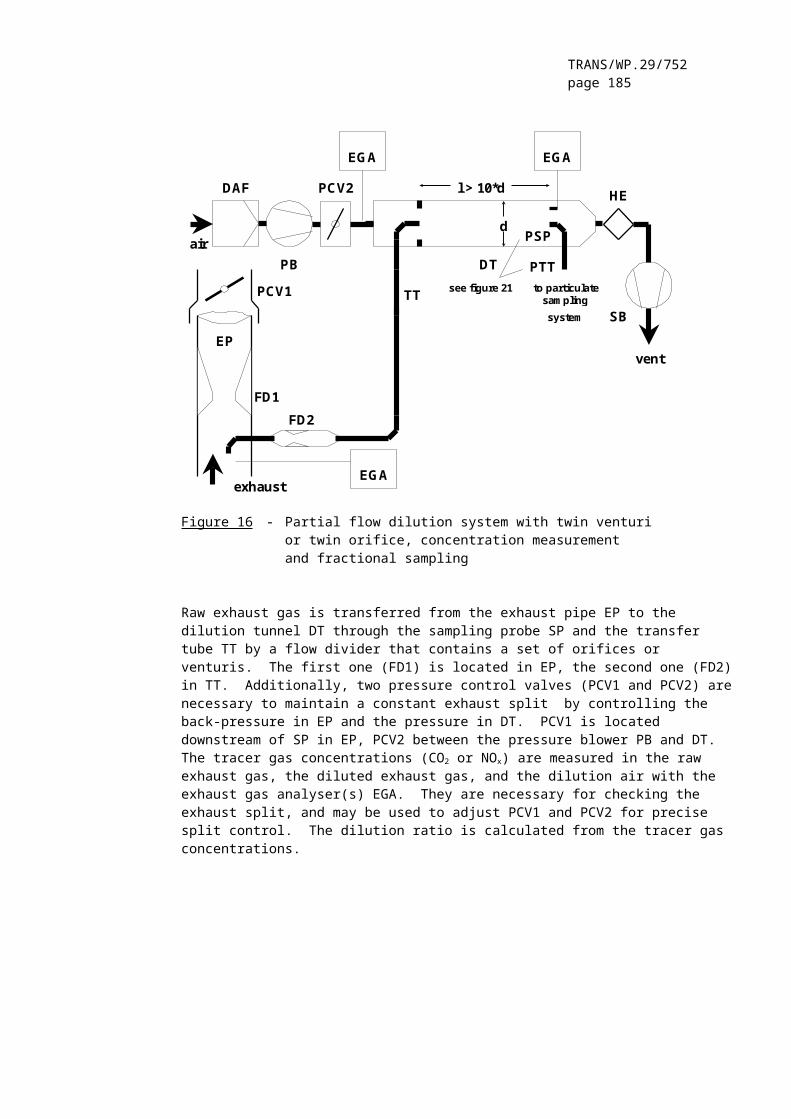
TRANS/WP.29/752page 185
3. ETC TEST
3.1. Gaseous emissions (Diesel engine)
Assume the following test results for a PDP-CVS system
V0 (m3/rev) 0.1776Np (rev) 23073pB (kPa) 98.0p1 (kPa) 2.3T (K) 322.5Ha (g/kg) 12.8NOx conce (ppm) 53.7NOx concd (ppm) 0.4CO conce (ppm) 38.9CO concd (ppm) 1.0HC conce (ppm) 9.00HC concd (ppm) 3.02CO2,conce (%) 0.723Wact (kWh) 62.72
Calculation of the diluted exhaust gas flow (annex 4, appendix 2, paragraph 4.1.):
MTOTW = 1.293 * 0.1776 * 23073 * (98.0 - 2.3) * 273 / (101.3 * 322.5) = 4237.2 kg
Calculation of the NOx correction factor (annex 4, appendix 2, paragraph 4.2.):
KH,D = = 1.039
Calculation of the background corrected concentrations (annex 4, appendix 2, paragraph 4.3.1.1.):
Assuming a diesel fuel of the composition C1H1.8
FS = = 13.6
DF = = 18.69
NOx conc = 53.7 - 0.4 * (1 - (1/18.69)) = 53.3 ppmCOconc = 38.9 - 1.0 * (1 - (1/18.69)) = 37.9 ppmHCconc = 9.00 - 3.02 * (1 - (1/18.69)) = 6.14 ppm
Calculation of the emissions mass flow (annex 4, appendix 2, paragraph 4.3.1.):
NOx mass = 0.001587 * 53.3 * 1.039 * 4237.2 = 372.391 gCOmass = 0.000966 * 37.9 * 4237.2 = 155.129 g
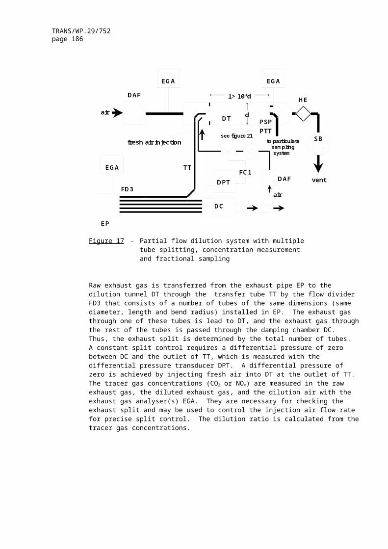
TRANS/WP.29/752page 186
HCmass = 0.000479 * 6.14 * 4237.2 = 12.462 g
Calculation of the specific emissions (annex 4, appendix 2, paragraph 4.4.):
3.2. Particulate Emissions (Diesel Engine)
Assume the following test results for a PDP-CVS system with double dilution
MTOTW (kg) 4237.2Mf,p (mg) 3.030Mf,b (mg) 0.044MTOT (kg) 2.159MSEC (kg) 0.909Md (mg) 0.341MDIL (kg) 1.245DF 18.69Wact (kWh) 62.72
Calculation of the mass emission (annex 4, appendix 2, paragraph 5.1.):
Mf = 3.030 + 0.044 = 3.074 mg
MSAM = 2.159 - 0.909 = 1.250 kg
Calculation of the background corrected mass emission (annex 4, appendix 2, paragraph 5.1.):
Calculation of the specific emission (annex 4, appendix 2, paragraph 5.2):
3.3. Gaseous emissions (CNG engine)
Assume the following test results for a PDP-CVS system with double dilution
MTOTW (kg) 4237.2Ha (g/kg) 12.8

TRANS/WP.29/752page 187
NOx conce (ppm) 17.2NOx concd (ppm) 0.4CO conce (ppm) 44.3CO concd (ppm) 1.0HC conce (ppm) 27.0HC concd (ppm) 3.02CH4 conce (ppm) 18.0CH4 concd (ppm) 1.7CO2,conce (%) 0.723Wact (kWh) 62.72
Calculation of the NOx correction factor (annex 4, appendix 2, paragraph 4.2.):
Calculation of the NMHC concentration (annex 4, appendix 2, paragraph 4.3.1.):
a) GC method
NMHCconce = 27.0 - 18.0 = 9.0 ppm
b) NMC method
Assuming a methane efficiency of 0.04 and an ethane efficiency of 0.98 (see annex 4, appendix 5, paragraph 1.8.4.)
Calculation of the background corrected concentrations (annex 4, appendix 2, paragraph 4.3.1.1.):
Assuming a G20 reference fuel (100 % methane) of the composition C1H4
For NMHC, the background concentration is the difference between HCconcd
and CH4 concd
NOx conc = 17.2 - 0.4 * (1 - (1/13.01)) = 16.8 ppmCOconc = 44.3 - 1.0 * (1 - (1/13.01)) = 43.4 ppmNMHCconc = 8.4 - 1.32 * (1 - (1/13.01)) = 7.2 ppmCH4 conc = 18.0 - 1.7 * (1 - (1/13.01)) = 16.4 ppm
Calculation of the emissions mass flow (annex 4, appendix 2, paragraph 4.3.1.):

TRANS/WP.29/752page 188
NOx mass = 0.001587 * 16.8 * 1.074 * 4237.2 =121.330 gCOmass = 0.000966 * 43.4 * 4237.2 = 177.642 gNMHCmass = 0.000502 * 7.2 * 4237.2 = 15.315 gCH4 mass = 0.000554 * 16.4 * 4237.2 = 38.498 g
Calculation of the specific emissions (annex 4, appendix 2, paragraph 4.4.):
= 121.330/62.72 = 1.93 g/kWh= 177.642/62.72 = 2.83 g/kWh= 15.315/62.72 = 0.244 g/kWh= 38.498/62.72 = 0.614 g/kWh
4. λ-SHIFT FACTOR (Sλ)
4.1. Calculation of the λ-shift factor (Sλ) ( 2 )
where:
Sλ = λ-shift factor;inert % = % by volume of inert gases in the fuel (i.e. N2, CO2, He,
etc.);O2* = % by volume of original oxygen in the fuel;n and m = refer to average CnHm representing the fuel hydrocarbons,
i.e:
where:
CH4 = % by volume of methane in the fuel;
2 (?)Stoichiometric Air/Fuel ratios of automotive fuels: SAE J1829, June 1987.John B. Heywood, Internal Combustion Engine Fundamentals, McGraw-Hill, 1988, Chapter 3.4. “Combustion stoichiometry”(pages 68 to 72).
TRANS/WP.29/752page 189
C2 = % by volume of all C2 hydrocarbons (e.g.: C2H6, C2H4, etc.) in the fuel;
C3 = % by volume of all C3 hydrocarbons (e.g.: C3H8, C3H6, etc.) in the fuel;
C4 = % by volume of all C4 hydrocarbons (e.g.: C4H10, C4H8, etc.) in the fuel;
C5 = % by volume of all C5 hydrocarbons (e.g.: C5H12, C5H10, etc.) in the fuel;
diluent = % by volume of dilution gases in the fuel (i.e.: O2*, N2, CO2, He, etc.).
4.2. Examples for the calculation of the λ-shift factor Sλ:
Example 1: G25: CH4 = 86%, N2 = 14% (by vol)

TRANS/WP.29/752page 190
Example 2: Gxy: CH4 = 87 %, C2H6 = 13 % (by vol)
Example 3: USA: CH4 = 89 %, C2H6 = 4.5 %, C3H8 = 2.3 %, C6H14 = 0.2 %, O2
= 0.6 %, N2 = 4%
__________"