Andreas Lagg MPI for Solar System Research Katlenburg-Lindau, Germany [email protected].

──────────────────────────────────────────────────────────────
Section 5──────────────────────────────────────────────────────────────
Telemetry
SUMER Operations Guide5 -

Section Contents
_______________________________________________________________________
5 TELEMETRY 5-3
5.1 General Description 5-3
5.2 Housekeeping Data Packets 5-4
5.3 Science Data Packets 5-4
5.3.1 SUMER Synchronization Word 5-5
5.3.2 Record Type Word 5-5
5.3.3 Image Records 5-5
5.3.4 Housekeeping Records 5-6
5.4 Housekeeping Data Channels 5-10
5.4.1 SUMER Housekeeping Data Sources List 5-12
5.4.1.1 HK Data from SPU, ECP, and Boot Controller 5-12
5.4.1.2 HK Data from Spacecraft Interface 5-12
5.4.1.3 HK Data from Power Converter Unit 5-13
5.4.1.4 HK Data from Motor Controller Electronics 5-13
5.4.1.5 HK Data from Rear Slit Camera Electronics 5-14
5.4.1.6 HK Data from Image Integration Memory 5-14
5.4.1.7 HK Data from Detector Electronics 5-15
5.4.1.8 HK Data from Telecommands 5-16
5.4.1.9 HK Data from Software Parameter Lists 5-16
5.4.1.10 HK Data from DPU 5-16
5.4.1.11 HK Data from DPU Software 5-16
5.4.2 SOHO SUMER Housekeeping Data Packet 5-17
5.4.2.1 Synopsis 5-17
5.4.2.2 Detailed Description 5-21
5.4.3 SUMER Housekeeping Records 5-43
5.4.3.1 SUMER HK Record 200 Idle Frame 5-43─
SUMER Operations Guide5 -

5.4.3.2 SUMER HK Record 248 Software Parameter List 5-44─
5.4.3.3 SUMER HK Record 249 Telecommand Result 5-46─
5.4.3.4 SUMER HK Record 250 Voltages and Currents 5-47─
5.4.3.5 SUMER HK Record 251 Motor Controller Data 5-50─
5.4.3.6 SUMER HK Record 252 Detector Data 5-52─
5.4.3.7 SUMER HK Record 255 Cycle Time 1 s 5-55─
5.4.4 SUMER Image Record Header Block 5-57
5.4.4.1 Synopsis 5-57
5.4.4.2 Detailed Description 5-59
_______________________________________________________________________
SUMER Operations Guide5 -

5 TELEMETRY
5.1 General Description
The SUMER telemetry data layout complies with the telemetry protocol of
Section 3.3.3 in: ESA Noordwijk, "SOHO Experiment Interface Document Part
A", PLP/410S/EID A, Issue 1.
The SUMER data are delivered to the SOHO spacecraft on two virtual
channels. A special set of housekeeping data is transferred via virtual
channel 0 while both science and housekeeping data are transmitted via
virtual channel 1.
Table 5-1
________________________________________________________________________________| SUMER Telemetry Source Packets per Format ||______________________________________________________________________________|| SOHO Spacecraft OBDH SUMER || data |TM |virt. |no. of |packet |packet |packet |data |packet |transm.|| rate |mode|channel|packets|header |time |time |type |data |total || | | | |(bytes)|(bytes)|(bytes)| |(bytes)|(bytes)||______|____|_______|_______|_______|_______|_______|__________|_______|_______|| low | - | 0 | 1 | 6 | 6 | 0 | HK | 188 | ≈50 || |____|_______|_______|_______|_______|_______|__________|_______|_______|| | - | 1 | - | - | - | - |science+HK| - | - ||______|____|_______|_______|_______|_______|_______|__________|_______|_______|| | - | 0 | 1 | 6 | 6 | 0 | HK | 188 | 188 || |____|_______|_______|_______|_______|_______|__________|_______|_______||medium| 1 | 1 | 48 | 6 | 0 | 6 |science+HK| 410 |19968 || |____|_______|_______|_______|_______|_______|__________|_______|_______|| / | 2 | 1 | 0 | 0 | 0 | 0 |science+HK| 0 | 0 || |____|_______|_______|_______|_______|_______|__________|_______|_______|| high | 3 | 1 | 0 | 0 | 0 | 0 |science+HK| 0 | 0 || |____|_______|_______|_______|_______|_______|__________|_______|_______|| | 4 | 1 | 96 | 6 | 0 | 6 |science+HK| 410 |39936 ||______|____|_______|_______|_______|_______|_______|__________|_______|_______|
Annotations
While in low data rate, the spacecraft will collect all 188 bytes housekeeping
(HK) data but will transmit to ground the first 50 bytes only. Consequently,
SUMER Operations Guide5 -
the housekeeping bytes are ordered according to their importance.
The data will be collected by the spacecraft as a fixed sequence of packets of
fixed length. The amount of data collected by the spacecraft depends on the
spacecraft telemetry mode (see Table 5-1).
The transfer of data packets is initiated by BCP1 (i.e. the telemetry major
frame pulse with a periodicity of 14.98828 sec). The time between two BCP1
defines one format.
Every data packet that is transmitted to ground is supplied with leading 6-
byte header and 6-byte time information. The science data packet time
information has to be written by the experiment itself and is therefore
included in the budget in Table 5-1. The time information for the
housekeeping data packets will be added by the spacecraft OBDH. The
header information for all packets will be written by the OBDH only.
Table 5-1 contains the number of housekeeping and science data packets
that are transmitted to and collected by the spacecraft in the different
spacecraft telemetry modes.
5.2 Housekeeping Data Packets
Once per format, i.e. once per 14.98828 seconds, the SOHO spacecraft will
collect 188 bytes of housekeeping data from SUMER and transport them to
the spacecraft OBDH on virtual channel 0.
While all 188 bytes will be transmitted whenever telemetry is in the high
data rate, only the first 50 bytes will be transmitted in the low data rate
telemetry mode.
Consequently, the housekeeping bytes are ordered according to their
SUMER Operations Guide5 -
importance. Chapter 5.4.2 contains a detailed list of these HK data delivered
by SUMER.
5.3 Science Data Packets
The science data packets, transmitted to the spacecraft OBDH on virtual
channel 1, are the basis for the transport of SUMER science and
housekeeping data. In TM mode 1, 48 packets, in TM mode 4, 96 packets of
410 bytes each are transferred during one format.
The SUMER housekeeping and science data are embedded consecutively in
the remaining 404 bytes of the data packets. Due to the different structure of
the SUMER data layout and the spacecraft OBDH packets, the SUMER data
are embedded floating in the science data packets, i.e. SUMER
synchronization (sync) words cannot be found at fixed places of the science
data packets.
The SUMER science and housekeeping data are logically divided into records.
The two types of records, image and housekeeping records, are of even
length. Every record starts with the 2-byte sync word and is followed by the
2-byte record type word. Table 5-2 gives an example of the SUMER telemetry
data layout.
Image records are subdivided into blocks. The leading image record header
block contains the sync word, continues with the type word, and is followed
by the image descriptor data. After the image record header block, a number
of data blocks may follow. Data blocks consist of the leading 2-byte sync
word and the 2-byte block counter and are followed by the image data.
Housekeeping records consist of single data blocks. These blocks contain, in
addition to the 2-byte sync word and the 2-byte record type word, the
SUMER Operations Guide5 -

housekeeping data words. The total length of the data records may be
derived from Table 5-3.
5.3.1 SUMER Synchronization Word
Every data record and every data block is initiated by a synchronization
(sync) word. The sync word is of 2-byte length with the following pattern:
EB90 (hex)
5.3.2 Record Type Word
Every data record starts with the SUMER sync word. The sync word is
followed by a 2-byte type word, the first of which contains 80 (hex) for image
records and 81 (hex) for housekeeping records. The second byte contains the
record type byte and may be derived from Table 5-3 for image records and
from Table 5-4 for housekeeping records.
The record type byte for image records is a positive number while the record
type byte for housekeeping records is negative. With the knowledge of the
record type byte, the length of the respective record/block may be obtained.
5.3.3 Image Records
A SUMER image record is subdivided into blocks, the first of which is the
record header block, followed by 0 to 2048 record data blocks.
Image record header blocks start with the 2-byte sync word, followed by the
2-byte record type word and the image descriptor data. The image descriptor
data contain all the information necessary for a correct image interpretation.
The length of the image record header block is 92 bytes.
SUMER Operations Guide5 -

Data blocks are introduced by a 2-byte sync word and a 2-byte block counter.
The block counter of the first data block contains 0.
SUMER Operations Guide5 -

5.3.4 Housekeeping Records
A housekeeping record consists of the sync word, the record type word, and
the housekeeping words. The length of the record depends on the record
type (cf. table 5-4). Housekeeping records may be transmitted directly before
another record (housekeeping or image) or after the transmission of at least
four image data blocks.
Seven different housekeeping records are defined: One housekeeping record
(HK record 255) will be transmitted periodically once per second. Five
housekeeping records will be transmitted on request or related to special
actions in the experiment. One housekeeping record (HK record 200) is an
idle frame of 404 bytes that will be transmitted whenever no other record is
available. It contains a test pattern consisting of consecutive byte sized
values (00 (hex) .. FF (hex), 00 (hex) .. 8B (hex)).
SUMER Operations Guide5 -

Table 5-2 SUMER Data Record Layout
___________________________________________________________________| SUMER data record layout ||_________________________________________________________________|image record header block___________________________________________________________________| sync word | type word | image descriptor data || (EB) | (90) | (80) | (type) | 1 | 2 | 3 | 4 ... k-2 | k-1 | k ||______|______|______|________|___|___|___|_____________|_____|___|image record data blocks___________________________________________________________________| sync word | block counter | image data || (EB) | (90) | (00) | (00) | 1 | 2 | 3 | 4 ... m-2 | m-1 | m ||______|______|______|________|___|___|___|_____________|_____|___|| sync word | block counter | image data || (EB) | (90) | (00) | (01) | 1 | 2 | 3 | 4 ... m-2 | m-1 | m ||______|______|______|________|___|___|___|_____________|_____|___|| sync word | block counter | image data || (EB) | (90) | (00) | (02) | 1 | 2 | 3 | 4 ... m-2 | m-1 | m ||______|______|______|________|___|___|___|_____________|_____|___|| sync word | block counter | image data || (EB) | (90) | (00) | (03) | 1 | 2 | 3 | 4 ... m-2 | m-1 | m ||______|______|______|________|___|___|___|_____________|_____|___|interleaved housekeeping record___________________________________________________________________| sync word | type word | housekeeping data || (EB) | (90) | (81) | (type) | 1 | 2 | 3 | 4 ... h-2 | h-1 | h ||______|______|______|________|___|___|___|_____________|_____|___|image record data blocks (continued)___________________________________________________________________| sync word | block counter | image data || (EB) | (90) | (00) | (04) | 1 | 2 | 3 | 4 ... m-2 | m-1 | m ||______|______|______|________|___|___|___|_____________|_____|___|..___________________________________________________________________| sync word | block counter | image data || (EB) | (90) | (n-2) | 1 | 2 | 3 | 4 ... m-2 | m-1 | m ||______|______|______|________|___|___|___|_____________|_____|___|| sync word | block counter | image data || (EB) (90) | (n-1) | 1 | 2 | 3 | 4 ... m-2 | m-1 | m ||______|______|______|________|___|___|___|_____________|_____|___|next image record header block___________________________________________________________________| sync word | type word | image descriptor data || (EB) | (90) | (80) | (type) | 1 | 2 | 3 | 4 ... k-2 | k-1 | k ||______|______|______|________|___|___|___|_____________|_____|___|image record data blocks___________________________________________________________________| sync word | block counter | image data || (EB) | (90) | (00) | (00) | 1 | 2 | 3 | 4 ... m-2 | m-1 | m ||______|______|______|________|___|___|___|_____________|_____|___|..
Annotations
a)The length information for h (housekeeping data), k (image descriptor), m
SUMER Operations Guide5 -

(data block data) and n (data block counter) may be derived from the
respective tables in this chapter.
b)A housekeeping record may occur only before one other record
(housekeeping or science) or after the transmission of at least four image
record data blocks.
SUMER Operations Guide5 -

Table 5-3 SUMER Image Records
________________________________________________________________________________| SUMER Image Records ||______________________________________________________________________________||type| contents | size | arrangement |res.| n a)| m b)| Tx e)|| c) | | | | d)| |[bytes]| [s] ||____|__________________|____________|_____________|____|______|_______|_______|| 2 | spatial spectrum | 1024 x 360 | spec x spat | B1 | 1024 | 360 | 281 || 3 | spatial spectrum | 1024 x 360 | spec x spat | B2 | 1024 | 720 | 562 || 4 | spatial spectrum | 1024 x 120 | spec x spat | B1 | 1024 | 120 | 94 || 5 | spatial spectrum | 1024 x 120 | spec x spat | B2 | 1024 | 240 | 187 || 8 | spatial line | 50 x 360 | line x spat | B1 | 50 | 360 | 14 || 9 | spatial line | 50 x 360 | line x spat | B2 | 50 | 720 | 28 || 10 | spatial line | 50 x 120 | line x spat | B1 | 50 | 120 | 4.6 || 11 | spatial line | 50 x 120 | line x spat | B2 | 50 | 240 | 9.2 || 12 | spatial line | 25 x 360 | line x spat | B1 | 25 | 360 | 7 || 13 | spatial line | 25 x 360 | line x spat | B2 | 25 | 720 | 14 || 14 | spatial line | 25 x 120 | line x spat | B1 | 25 | 120 | 2.3 || 15 | spatial line | 25 x 120 | line x spat | B2 | 25 | 240 | 4.6 || 18 | spatial parameter| 1 x 360 | scal x spat | I2 | 1 | 720 | 0.6 || 19 | spatial parameter| 1 x 360 | scal x spat | R4 | 1 | 1440 | 0.8 || 20 | spatial parameter| 1 x 120 | scal x spat | I2 | 1 | 240 | 0.2 || 21 | spatial parameter| 1 x 120 | scal x spat | R4 | 1 | 480 | 0.3 || 24 | scanned image | 300 x 360 | spat x spat | I2 | 300 | 720 | 165 || 25 | scanned image | 300 x 360 | spat x spat | R4 | 300 | 1440 | 247 || 26 | scanned image | 300 x 120 | spat x spat | I2 | 300 | 240 | 55 || 27 | scanned image | 300 x 120 | spat x spat | R4 | 300 | 480 | 83 || 30 | section line | 25 x 24 | line x spat | B1 | 1 | 600 | 0.5 || 31 | section line | 50 x 24 | line x spat | B1 | 1 | 1200 | 1.0 || 34 | rear slit | 1 x 512 | spatial | B1 | 1 | 512 | 0.5 || 35 | rear slit scan | 50 x 512 | spat x spat | B1 | 50 | 512 | 20 || 36 | history memory | 512 x 20 | spec x spat | B4 | 512 | 80 | 32 || 37 | calibrat. format | 256 x 360 | spec x spat | B2 | 256 | 720 | 141 || 38 | half detector | 512 x 360 | spec x spat | B1 | 512 | 360 | 141 || 39 | half detector | 512 x 360 | spec x spat | B2 | 512 | 720 | 281 || 40 | celestial objects| 1024 x 12 | spec x spat | B1 | 1024 | 12 | 9 || 41 | spatial parameter| 2 x 360 | scal x spat | I2 | 2 | 720 | 1.2 || 42 | spatial parameter| 2 x 120 | scal x spat | I2 | 2 | 240 | 0.4 || 43 | spatial parameter| 4 x 360 | scal x spat | I2 | 4 | 720 | 2.4 || 44 | spatial parameter| 4 x 120 | scal x spat | I2 | 4 | 240 | 0.8 || 45 | spatial parameter| 5 x 360 | scal x spat | B1 | 5 | 360 | 1.5 ||____|__________________|____________|_____________|____|______|_______|_______|
Annotations
a)n is the number of image record data blocks per image record.
b)m is the length of one image record data block (not including 2-byte sync
word and 2-byte block counter).
c)Image formats 32 and 33 have been deleted.
Image format 36 is only used by the DPU to dump the history memory.
Image formats to be used by spectrohelio, see Section 8 (SCL functions), p.
8-52.
SUMER Operations Guide5 -

d)Bx is an unsigned integer with x bytes.
e)Tx is the estimated telemetry transmission time in seconds at 10.5 kBaud,
overhead by HK records neglected.
SUMER Operations Guide5 -

Table 5-4 SUMER Housekeeping Records
__________________________________________________________________| SUMER Housekeeping Records ||________________________________________________________________|| type | length | description | frequency ||______|________|___________________________________|____________|| 255 | 26 | data set transmitted cyclically | 1 / s || 252 | 56 | detector electronics data | on request || 251 | 26 | motor controller electronics data | on request || 250 | 38 | power converter electronics data | on request || 249 | 72 | telecommand result | on request || 248 | 72 | software parameter list | on request || 200 | 404 | idle frame | if TM idle ||______|________|___________________________________|____________|
SUMER Operations Guide5 -
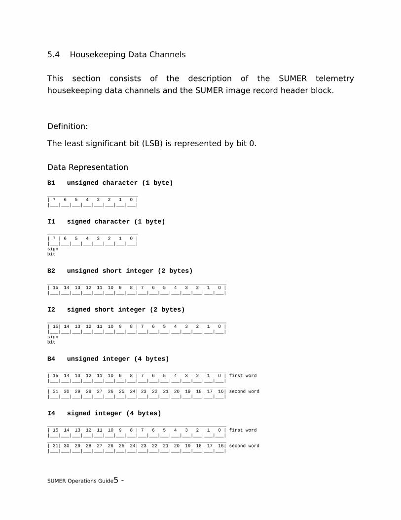
5.4 Housekeeping Data Channels
This section consists of the description of the SUMER telemetry
housekeeping data channels and the SUMER image record header block.
Definition:
The least significant bit (LSB) is represented by bit 0.
Data Representation
B1 unsigned character (1 byte)
_________________________________| 7 6 5 4 3 2 1 0 ||___|___|___|___|___|___|___|___|
I1 signed character (1 byte)
_________________________________| 7 | 6 5 4 3 2 1 0 ||___|___|___|___|___|___|___|___|signbit
B2 unsigned short integer (2 bytes)
_________________________________________________________________| 15 14 13 12 11 10 9 8 | 7 6 5 4 3 2 1 0 ||___|___|___|___|___|___|___|___|___|___|___|___|___|___|___|___|
I2 signed short integer (2 bytes)
_________________________________________________________________| 15| 14 13 12 11 10 9 8 | 7 6 5 4 3 2 1 0 ||___|___|___|___|___|___|___|___|___|___|___|___|___|___|___|___|signbit
B4 unsigned integer (4 bytes)
_________________________________________________________________| 15 14 13 12 11 10 9 8 | 7 6 5 4 3 2 1 0 | first word|___|___|___|___|___|___|___|___|___|___|___|___|___|___|___|___|_________________________________________________________________| 31 30 29 28 27 26 25 24| 23 22 21 20 19 18 17 16| second word|___|___|___|___|___|___|___|___|___|___|___|___|___|___|___|___|
I4 signed integer (4 bytes)
_________________________________________________________________| 15 14 13 12 11 10 9 8 | 7 6 5 4 3 2 1 0 | first word|___|___|___|___|___|___|___|___|___|___|___|___|___|___|___|___|_________________________________________________________________| 31| 30 29 28 27 26 25 24| 23 22 21 20 19 18 17 16| second word|___|___|___|___|___|___|___|___|___|___|___|___|___|___|___|___|
SUMER Operations Guide5 -

signbit
_________________________________________________________________| 15 14 13 12 11 10 9 8 | 7 6 5 4 3 2 1 0 | first word|___|___|___|___|___|___|___|___|___|___|___|___|___|___|___|___|------------------------ fractional part -----------------------|
_________________________________________________________________| 31| 30 29 28 27 26 25 24| 23| 22 21 20 19 18 17 16| second word|___|___|___|___|___|___|___|___|___|___|___|___|___|___|___|___|Sign|--------- exponent ------------|----- fractional part ------bit
The value is positive if the sign bit is 0, negative if the sign bit is 1.The magnitude of the value is:
(2(exponent-127))*1.fraction if 0 < exponent < 255
0 if exponent = 0 and fraction = 0
(2-126)*0.fraction (i.e. practically 0) if exponent = 0 and fraction # 0
infinite if exponent = 255
SUMER Operations Guide5 -

SOHO SUMER Housekeeping Data Packet ─ Detailed Description (cont.)
5.4.1 SUMER Housekeeping Data Sources List
This section lists the housekeeping (HK) data channels grouped together
according to their sources. Since the SUMER DPU swaps the bytes, the
SUMER TM data shows a different layout.
This list does not reflect the TM layout!
In this chapter, the following abbreviations are used to represent the
housekeeping channels used and the image record header block :
HK:xxx SOHO SUMER Housekeeping Data Packet, location xxxPOW:yy SUMER Housekeeping Record 250, location yyMC:zz SUMER Housekeeping Record 251, location zzDET:aa SUMER Housekeeping Record 252, location aaCY:bb SUMER Housekeeping Record 255, location bb
5.4.1.1 HK Data from SPU, ECP, and Boot Controller
type tmname contents transmitted in──────────────────────────────────────────────────────────────B1 SSECPBSR ECP Bank Select Register HK:45B1 SSECPB ECP Bank Registers HK:44B1 SSECPERR ECP Error Status Register HK:47 CY:14B1 SSSPUBSR SPU Bank Select Register HK:46B1 SSSPUB SPU Bank Registers HK:49B1 SSSPUERR SPU Error Status Register HK:48 CY:15B2 SSCU1 CU1 Config Register HK:50B2 SSCU2 CU2 Config Register HK:52B2 SSBCREG Boot Controller Configuration Register Actual BC HK:54B2 SSBCVAL Boot Controller Configuration Value Actual BC HK:56──────────────────────────────────────────────────────────────14 bytes
5.4.1.2 HK Data from Spacecraft Interface
type tmname contents transmitted in──────────────────────────────────────────────────────────────
SUMER Operations Guide5 -
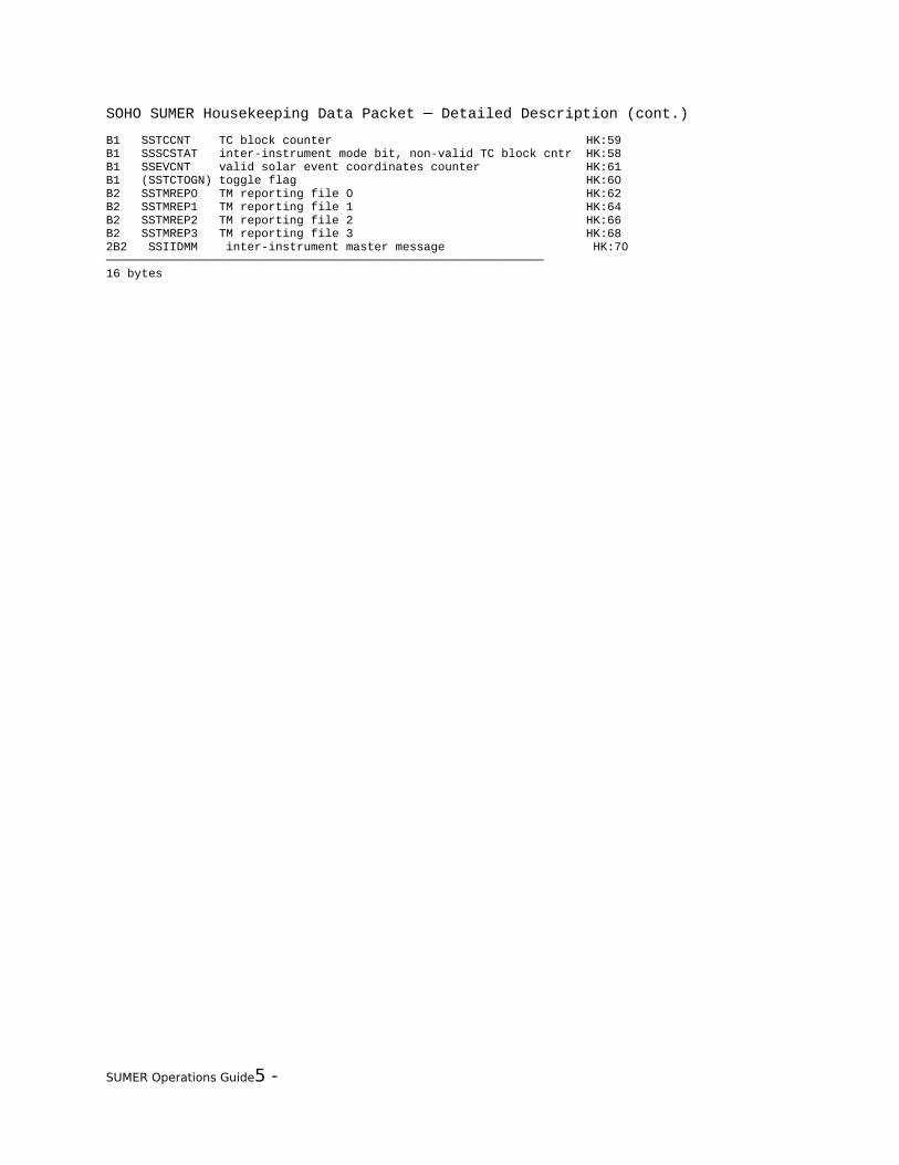
SOHO SUMER Housekeeping Data Packet ─ Detailed Description (cont.)
B1 SSTCCNT TC block counter HK:59B1 SSSCSTAT inter-instrument mode bit, non-valid TC block cntr HK:58B1 SSEVCNT valid solar event coordinates counter HK:61B1 (SSTCTOGN) toggle flag HK:60B2 SSTMREP0 TM reporting file 0 HK:62B2 SSTMREP1 TM reporting file 1 HK:64B2 SSTMREP2 TM reporting file 2 HK:66B2 SSTMREP3 TM reporting file 3 HK:682B2 SSIIDMM inter-instrument master message HK:70──────────────────────────────────────────────────────────────16 bytes
SUMER Operations Guide5 -

SOHO SUMER Housekeeping Data Packet ─ Detailed Description (cont.)
5.4.1.3 HK Data from Power Converter Unit
type tmname contents transmitted in──────────────────────────────────────────────────────────────B1 SSPOW0 Status 0 power converter ch 0 HK: 1 POW: 9B1 SSPOW1 Status 1 power converter ch 1 HK: 0 POW: 8B1 SSPOW2 Status 2 power converter ch 2 HK: 3 POW:11B1 SSPOW3 Status 3 power converter ch 3 HK: 2 POW:10B1 SSPOW4 STATUS 4 power converter ch 4 HK: 5 POW:13B1 spare power converter ch 5 HK:-- POW:--B1 spare power converter ch 6 HK:-- POW:--B1 spare power converter ch 7 HK:-- POW:--B1 SIDETA IDetA power converter ch 8 HK: 9 POW:17B1 SIDETB IDetB power converter ch 9 HK: 8 POW:16B1 SIHEATRD IHeaterD power converter ch 10 HK:11 POW:19B1 spare power converter ch 11 HK:10 POW:18B1 SIDEFL IDefl power converter ch 12 HK:13 POW:21B1 SIWAXMOT IWaxMotor Door power converter ch 13 HK:12 POW:20B1 SIBRD+28 IBoard +28V power converter ch 14 HK:15 POW:23B1 S+28VBRD VBoard +28V power converter ch 15 HK:14 POW:22B1 SICC+5 ICC +5V power converter ch 16 HK:17 POW:25B1 S+5VCC VCC +5V power converter ch 17 HK:16 POW:24B1 SIDD1+18 IDD1 +18V power converter ch 18 HK:19 POW:27B1 S+18VDD1 VDD1 +18V power converter ch 19 HK:18 POW:26B1 SIDD2+18 IDD2 +18V power converter ch 20 HK:21 POW:29B1 S+18VDD2 VDD2 +18V power converter ch 21 HK:20 POW:28B1 SIBB1-18 IBB1 -18V power converter ch 22 HK:23 POW:32B1 S-18VBB1 VBB1 -18V power converter ch 23 HK:22 POW:31B1 SIBB2-18 IBB2 -18V power converter ch 24 HK:25 POW:34B1 S-18VBB2 VBB2 -18V power converter ch 25 HK:24 POW:33B1 SIRSC+15 IDDRSC +15V power converter ch 26 HK:27 POW:36B1 S+15VRSC VDDRSC +15V power converter ch 27 HK:26 POW:35B1 SIRSC-15 IBBRSC -15V power converter ch 28 HK: 4 POW:12B1 S-15VRSC VBBRSC -15V power converter ch 29 HK: 7 POW:15B1 spare power converter ch 30 HK:-- POW:--B1 STSUMER4 temperature SUMER4 power converter ch 31 HK: 6 POW:14──────────────────────────────────────────────────────────────32 bytes
5.4.1.4 HK Data from Motor Controller Electronics
type tmname contents (MCx: MC1|MC2|MC3|MC4|MC5|MC6|MC8) transmitted in──────────────────────────────────────────────────────────────B1 SIMC+18M MCx +18V supply current / during motion HK:-- MC: 9B1 SIMC-18M MCx -18V supply current / during motion HK:-- MC: 8B1 SIMC+18R MCx +18V supply current / on request HK:-- MC:11B1 SIMC-18R MCx -18V supply current / on request HK:-- MC:10B1 S+15MC MCx +15V HK:75 + 6*n (n=0..6) MC:13B1 S-15MC MCx -15V HK:74 + 6*n (n=0..6) MC:12B1 S+5MC MCx +5V HK:78 + 6*n (n=0..6) MC:15B1 STMCT1 MCx temperature 1 (motor driver stage) HK:30 .. 37 MC:14B1 STMCT2 MCx temperature 2 (motor) HK:30 .. 37 MC:17B1 STMCT3 MCx temperature 3 (external temperature) HK:30 .. 37 MC:16B2 SSMCPOS MCx position (LVDT, RVDC, digital position encoder) HK:76 + 6*n (n=0..6) MC:18B1 SSMCINDX MCx index of motor bit pattern HK:-- MC:20B1 SSMC MCx status HK:79 + 6*n (n=0..6) MC:21B1 SE21 spare HK:-- MC:23
SUMER Operations Guide5 -
SOHO SUMER Housekeeping Data Packet ─ Detailed Description (cont.)
B2 (SE22) raw value of ADC output of external temperature 3 HK:-- MC:24──────────────────────────────────────────────────────────────17 bytes per MC = 119 bytes
SUMER Operations Guide5 -

SOHO SUMER Housekeeping Data Packet ─ Detailed Description (cont.)
5.4.1.5 HK Data from Rear Slit Camera Electronics
type tmname contents transmitted in──────────────────────────────────────────────────────────────B1 SE3 spare HK:122I1 SSRSC result from level 4 command RSC_ReadImage HK:123────────────────────────────────────────────────────────────── 2 bytes
5.4.1.6 HK Data from Image Integration Memory
type tmname contents transmitted in──────────────────────────────────────────────────────────────B2 SSIIM IIM status register HK:124 CY:16B1 SE 7 spare HK:126I1 SSIIMRES result from level 4 commands IIMxxxx HK:127────────────────────────────────────────────────────────────── 4 bytes
SUMER Operations Guide5 -
SOHO SUMER Housekeeping Data Packet ─ Detailed Description (cont.)
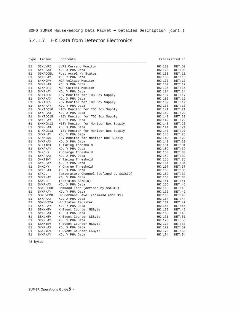
5.4.1.7 HK Data from Detector Electronics
type tmname contents transmitted in──────────────────────────────────────────────────────────────B1 SIXLVPI LVPS Current Monitor HK:129 DET:09B1 SYXPHAX XDL X PHA Data HK:128 DET:08B1 SSXACCEL Post Accel HV Status HK:131 DET:11B1 SYXPHAY XDL Y PHA Data HK:130 DET:10B1 S+XMCPV MCP Voltage Monitor HK:133 DET:13B1 SYXPHAX XDL X PHA Data HK:132 DET:12B1 SIXMCPI MCP Current Monitor HK:135 DET:15B1 SYXPHAY XDL Y PHA Data HK:134 DET:14B1 S+XTDC5 +5V Monitor for TDC Box Supply HK:137 DET:17B1 SYXPHAX XDL X PHA Data HK:136 DET:16B1 S-XTDC5 -5V Monitor for TDC Box Supply HK:139 DET:19B1 SYXPHAY XDL Y PHA Data HK:138 DET:18B1 S+XTDC10 +10V Monitor for TDC Box Supply HK:141 DET:21B1 SYXPHAX XDL X PHA Data HK:140 DET:20B1 S-XTDC15 -15V Monitor for TDC Box Supply HK:143 DET:23B1 SYXPHAY XDL Y PHA Data HK:142 DET:22B1 S+XMON13 +13V Monitor for Monitor Box Supply HK:145 DET:25B1 SYXPHAX XDL X PHA Data HK:144 DET:24B1 S-XMON13 -13V Monitor for Monitor Box Supply HK:147 DET:27B1 SYXPHAY XDL Y PHA Data HK:146 DET:26B1 S+XMON5 +5V Monitor for Monitor Box Supply HK:149 DET:29B1 SYXPHAX XDL X PHA Data HK:148 DET:28B1 S+XTIMX X Timing Threshold HK:151 DET:31B1 SYXPHAY XDL Y PHA Data HK:150 DET:30B1 S+XCHX X Charge Threshold HK:153 DET:33B1 SYXPHAX XDL X PHA Data HK:152 DET:32B1 S+XTIMY Y Timing Threshold HK:155 DET:35B1 SYXPHAY XDL Y PHA Data HK:154 DET:34B1 S+XCHY Y Charge Threshold HK:157 DET:37B1 SYXPHAX XDL X PHA Data HK:156 DET:36B1 STXDL Temperature Channel (defined by SSXSID) HK:159 DET:39B1 SYXPHAY XDL Y PHA Data HK:158 DET:38B1 SSXDEF (contains SSXSID) HK:161 DET:41B1 SYXPHAX XDL X PHA Data HK:160 DET:40B1 SSXCECHO Command Echo (defined by SSXSID) HK:163 DET:43B1 SYXPHAY XDL Y PHA Data HK:162 DET:42B1 SSXHVCMD HV Command Level (command addr 11) HK:165 DET:45B1 SYXPHAX XDL X PHA Data HK:164 DET:44B1 SSXHVSTA HV Status Register HK:167 DET:47B1 SYXPHAY XDL Y PHA Data HK:166 DET:46B1 SSXMXEV X Event Counter MSByte HK:169 DET:49B1 SYXPHAX XDL X PHA Data HK:168 DET:48B1 SSXLXEV X Event Counter LSByte HK:171 DET:51B1 SYXPHAY XDL Y PHA Data HK:170 DET:50B1 SSXMYEV Y Event Counter MSByte HK:173 DET:53B1 SYXPHAX XDL X PHA Data HK:172 DET:52B1 SSXLYEV Y Event Counter LSByte HK:175 DET:55B1 SYXPHAY XDL Y PHA Data HK:174 DET:54──────────────────────────────────────────────────────────────48 bytes
SUMER Operations Guide5 -
SOHO SUMER Housekeeping Data Packet ─ Detailed Description (cont.)
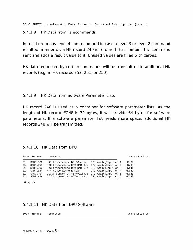
5.4.1.8 HK Data from Telecommands
In reaction to any level 4 command and in case a level 3 or level 2 command
resulted in an error, a HK record 249 is returned that contains the command
sent and adds a result value to it. Unused values are filled with zeroes.
HK data requested by certain commands will be transmitted in additional HK
records (e.g. in HK records 252, 251, or 250).
5.4.1.9 HK Data from Software Parameter Lists
HK record 248 is used as a container for software parameter lists. As the
length of HK record #248 is 72 bytes, it will provide 64 bytes for software
parameters. If a software parameter list needs more space, additional HK
records 248 will be transmitted.
5.4.1.10 HK Data from DPU
type tmname contents transmitted in──────────────────────────────────────────────────────────────B1 STDPUDCC HK1 temperature DC/DC conv. DPU AnalogInput ch 1 HK:39B1 STDPUCU1 HK2 temperature DPU-RAM CU1 DPU AnalogInput ch 2 HK:38B1 STDPUCU2 HK3 temperature DPU-RAM CU2 DPU AnalogInput ch 3 HK:41B1 STDPUEBX HK4 temperature E-Box DPU AnalogInput ch 4 HK:40B1 S+5VDPU DC/DC converter +5V/voltage DPU AnalogInput ch 5 HK:43B1 SIDPU+5V DC/DC converter +5V/current DPU AnalogInput ch 6 HK:42────────────────────────────────────────────────────────────── 6 bytes
5.4.1.11 HK Data from DPU Software
type tmname contents transmitted in──────────────────────────────────────────────────────────────
SUMER Operations Guide5 -

SOHO SUMER Housekeeping Data Packet ─ Detailed Description (cont.)
B1 SSHKMHIT HK monitor emergency switch-off index HK:120B1 SSHKMMODE emergency switch-on config mode HK:121B2 SKAFTRES AFT result (transmitted after the AFT has ended) HK:1469B1 SSCONFIG experiment configuration (as defined by TC) HK:178B1 SKEXPSTA experiment software status HK:187 CY: 8B1 SKCMDNR number of commands in command list CY: 9B2 SKUNCOMP number of uncompressed files in RAM disk CY:10B2 SKCOMP number of compressed files in RAM disk CY:12B2 SKL3ID L3 function identifier (MLB1) CY:18B1 SKL3RES L3 result CY:20B1 SKCMDLST command list disabled/enabled CY:21──────────────────────────────────────────────────────────────23 bytes
SUMER Operations Guide5 -

SOHO SUMER Housekeeping Data Packet ─ Detailed Description (cont.)
5.4.2 SOHO SUMER Housekeeping Data Packet
The SOHO SUMER housekeeping data packet is generated once per format
and is transported to the spacecraft OBDH on virtual channel 0.
The length of the SOHO SUMER Housekeeping Data Packet is 188 bytes. It is
transmitted once per format, i.e. every 15 seconds. The values are updated
at several different intervals that are indicated in the subheaders in the
detailed description.
5.4.2.1 Synopsis
loc type tmname contents source══════════════════════════════════════════════════════════════ 0 B1 SSPOW1 Status 1 power converter channel 1 Power Control Unit 1 B1 SSPOW0 Status 0 power converter channel 0 2 B1 SSPOW3 Status 3 power converter channel 3 3 B1 SSPOW2 Status 2 power converter channel 2 4 B1 SIRSC-15 IBBRSC -15V power converter channel 28 5 B1 SSPOW4 STATUS 4 power converter channel 4 6 B1 STSUMER4 temperature SUMER4 power converter channel 31 7 B1 S-15VRSC VBBRSC -15V power converter channel 29 8 B1 SIDETB IDetB power converter channel 9 9 B1 SIDETA IDetA power converter channel 810 B1 ---obsolete--- power converter channel 1111 B1 SIHEATRD IHeaterD power converter channel 1012 B1 SIWAXMOT IWaxMotor Door power converter channel 1313 B1 SIDEFL IDefl power converter channel 1214 B1 S+28VBRD VBoard +28V power converter channel 1515 B1 SIBRD+28 IBoard +28V power converter channel 1416 B1 S+5VCC VCC +5V power converter channel 1717 B1 SICC+5 ICC +5V power converter channel 1618 B1 S+18VDD1 VDD1 +18V power converter channel 1919 B1 SIDD1+18 IDD1 +18V power converter channel 1820 B1 S+18VDD2 VDD2 +18V power converter channel 2121 B1 SIDD2+18 IDD2 +18V power converter channel 2022 B1 S-18VBB1 VBB1 -18V power converter channel 2323 B1 SIBB1-18 IBB1 -18V power converter channel 2224 B1 S-18VBB2 VBB2 -18V power converter channel 2525 B1 SIBB2-18 IBB2 -18V power converter channel 2426 B1 S+15VRSC VDDRSC +15V power converter channel 2727 B1 SIRSC+15 IDDRSC +15V power converter channel 26══════════════════════════════════════════════════════════════28 B1 SSMCMC Motor Controller Motor Controller Electronics29 B1 SE1 spare ┌─────────────────────────────────────────────────────────────│ if byte 28 (SSMCMC) bit 0 (SSMC1MC) is 1 if SSMC1MC is
SUMER Operations Guide5 -
SOHO SUMER Housekeeping Data Packet ─ Detailed Description (cont.)
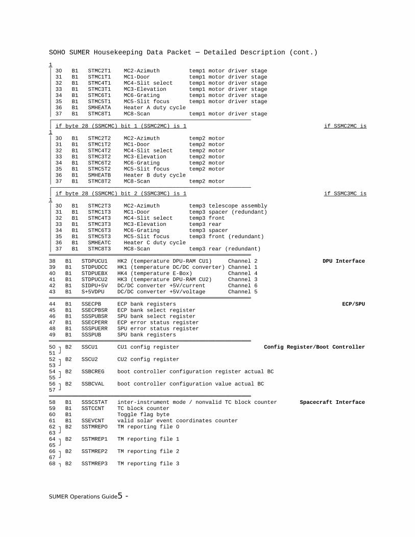
1│ 30 B1 STMC2T1 MC2-Azimuth temp1 motor driver stage│ 31 B1 STMC1T1 MC1-Door temp1 motor driver stage│ 32 B1 STMC4T1 MC4-Slit select temp1 motor driver stage│ 33 B1 STMC3T1 MC3-Elevation temp1 motor driver stage│ 34 B1 STMC6T1 MC6-Grating temp1 motor driver stage│ 35 B1 STMC5T1 MC5-Slit focus temp1 motor driver stage│ 36 B1 SMHEATA Heater A duty cycle│ 37 B1 STMC8T1 MC8-Scan temp1 motor driver stage┌─────────────────────────────────────────────────────────────│ if byte 28 (SSMCMC) bit 1 (SSMC2MC) is 1 if SSMC2MC is 1│ 30 B1 STMC2T2 MC2-Azimuth temp2 motor│ 31 B1 STMC1T2 MC1-Door temp2 motor│ 32 B1 STMC4T2 MC4-Slit select temp2 motor│ 33 B1 STMC3T2 MC3-Elevation temp2 motor│ 34 B1 STMC6T2 MC6-Grating temp2 motor│ 35 B1 STMC5T2 MC5-Slit focus temp2 motor│ 36 B1 SMHEATB Heater B duty cycle│ 37 B1 STMC8T2 MC8-Scan temp2 motor┌─────────────────────────────────────────────────────────────│ if byte 28 (SSMCMC) bit 2 (SSMC3MC) is 1 if SSMC3MC is 1│ 30 B1 STMC2T3 MC2-Azimuth temp3 telescope assembly│ 31 B1 STMC1T3 MC1-Door temp3 spacer (redundant)│ 32 B1 STMC4T3 MC4-Slit select temp3 front│ 33 B1 STMC3T3 MC3-Elevation temp3 rear│ 34 B1 STMC6T3 MC6-Grating temp3 spacer│ 35 B1 STMC5T3 MC5-Slit focus temp3 front (redundant)│ 36 B1 SMHEATC Heater C duty cycle│ 37 B1 STMC8T3 MC8-Scan temp3 rear (redundant)══════════════════════════════════════════════════════════════38 B1 STDPUCU1 HK2 (temperature DPU-RAM CU1) Channel 2 DPU Interface39 B1 STDPUDCC HK1 (temperature DC/DC converter) Channel 140 B1 STDPUEBX HK4 (temperature E-Box) Channel 441 B1 STDPUCU2 HK3 (temperature DPU-RAM CU2) Channel 342 B1 SIDPU+5V DC/DC converter +5V/current Channel 643 B1 S+5VDPU DC/DC converter +5V/voltage Channel 5══════════════════════════════════════════════════════════════44 B1 SSECPB ECP bank registers ECP/SPU45 B1 SSECPBSR ECP bank select register46 B1 SSSPUBSR SPU bank select register47 B1 SSECPERR ECP error status register48 B1 SSSPUERR SPU error status register49 B1 SSSPUB SPU bank registers══════════════════════════════════════════════════════════════50 ┐ B2 SSCU1 CU1 config register Config Register/Boot Controller51 ┘52 ┐ B2 SSCU2 CU2 config register53 ┘54 ┐ B2 SSBCREG boot controller configuration register actual BC55 ┘56 ┐ B2 SSBCVAL boot controller configuration value actual BC57 ┘══════════════════════════════════════════════════════════════58 B1 SSSCSTAT inter-instrument mode / nonvalid TC block counter Spacecraft Interface59 B1 SSTCCNT TC block counter60 B1 Toggle flag byte61 B1 SSEVCNT valid solar event coordinates counter62 ┐ B2 SSTMREP0 TM reporting file 063 ┘64 ┐ B2 SSTMREP1 TM reporting file 165 ┘66 ┐ B2 SSTMREP2 TM reporting file 267 ┘68 ┐ B2 SSTMREP3 TM reporting file 3
SUMER Operations Guide5 -

SOHO SUMER Housekeeping Data Packet ─ Detailed Description (cont.)
69 ┘70 ┐2B2 SSIIDMM inter-instrument master message71 ┘72 ┐73 ┘══════════════════════════════════════════════════════════════74 B1 S-15MC1 MC1-Door -15V Motor Controller Electronics (cont.) MC175 B1 S+15MC1 MC1-Door +15V76 ┐ B2 SSMC1POS MC1-Door encoder value77 ┘78 B1 S+5MC1 MC1-Door +5V79 B1 SSMC1 MC1-Door status──────────────────────────────────────────────────────────────80 B1 S-15MC2 MC2-Azimuth -15V MC281 B1 S+15MC2 MC2-Azimuth +15V82 ┐ B2 SSMC2POS MC2-Azimuth encoder value83 ┘84 B1 S+5MC2 MC2-Azimuth +5V85 B1 SSMC2 MC2-Azimuth status──────────────────────────────────────────────────────────────86 B1 S-15MC3 MC3-Elevation -15V MC387 B1 S+15MC3 MC3-Elevation +15V88 ┐ B2 SSMC3POS MC3-Elevation encoder value89 ┘90 B1 S+5MC3 MC3-Elevation +5V91 B1 SSMC3 MC3-Elevation status──────────────────────────────────────────────────────────────92 B1 S-15MC4 MC4-Slit select -15V MC493 B1 S+15MC4 MC4-Slit select +15V94 ┐ B2 SSMC4POS MC4-Slit select encoder value95 ┘96 B1 S+5MC4 MC4-Slit select +5V97 B1 SSMC4 MC4-Slit select status──────────────────────────────────────────────────────────────98 B1 S-15MC5 MC5-Slit focus -15V MC599 B1 S+15MC5 MC5-Slit focus +15V100 ┐ B2 SSMC5POS MC5-Slit focus encoder value101 ┘102 B1 S+5MC5 MC5-Slit focus +5V103 B1 SSMC5 MC5-Slit focus status──────────────────────────────────────────────────────────────104 B1 S-15MC6 MC6-Grating -15V MC6105 B1 S+15MC6 MC6-Grating +15V106 ┐ B2 SSMC6POS MC6-Grating encoder value107 ┘108 B1 S+5MC6 MC6-Grating +5V109 B1 SSMC6 MC6-Grating status──────────────────────────────────────────────────────────────110 B1 S-15MC8 MC8-Scan -15V MC8111 B1 S+15MC8 MC8-Scan +15V112 ┐ B2 SSMC8POS MC8-Scan IAS encoder value113 ┘114 B1 S+5MC8 MC8-Scan +5V115 B1 SSMC8 MC8-Scan status116 B1 spare 117 B1 SMHEAMOD Heater mode118 B1 SSHEATKS Heater ticks119 B1 spare══════════════════════════════════════════════════════════════120 B1 SSHKMHIT HK monitor emergency switch-off index Emergency Switch-Off and -On121 B1 SSHKMMODE emergency switch-on config mode══════════════════════════════════════════════════════════════122 B1 SE3 spare Rear Slit
SUMER Operations Guide5 -
SOHO SUMER Housekeeping Data Packet ─ Detailed Description (cont.)
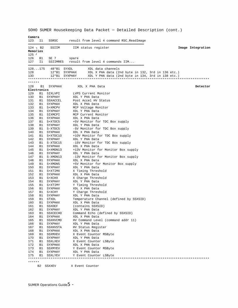
Camera123 I1 SSRSC result from level 4 command RSC_ReadImage══════════════════════════════════════════════════════════════124 ┐ B2 SSIIM IIM status register Image Integration Memories125 ┘126 B1 SE 7 spare 127 I1 SSIIMRES result from level 4 commands IIM...══════════════════════════════════════════════════════════════128...175 48*B1 SYXDL XDL data channels128 12*B1 SYXPHAX XDL X PHA data (2nd byte in 132, 3rd in 136 etc.)130 12*B1 SYXPHAY XDL Y PHA data (2nd byte in 134, 3rd in 138 etc.)*******************************************************************************************************128 B1 SYXPHAX XDL X PHA Data Detector Electronics129 B1 SIXLVPI LVPS Current Monitor130 B1 SYXPHAY XDL Y PHA Data131 B1 SSXACCEL Post Accel HV Status132 B1 SYXPHAX XDL X PHA Data133 B1 S+XMCPV MCP Voltage Monitor134 B1 SYXPHAY XDL Y PHA Data135 B1 SIXMCPI MCP Current Monitor136 B1 SYXPHAX XDL X PHA Data137 B1 S+XTDC5 +5V Monitor for TDC Box supply138 B1 SYXPHAY XDL Y PHA Data139 B1 S-XTDC5 -5V Monitor for TDC Box supply140 B1 SYXPHAX XDL X PHA Data141 B1 S+XTDC10 +10V Monitor for TDC Box supply142 B1 SYXPHAY XDL Y PHA Data143 B1 S-XTDC15 -15V Monitor for TDC Box supply144 B1 SYXPHAX XDL X PHA Data145 B1 S+XMON13 +13V Monitor for Monitor Box supply146 B1 SYXPHAY XDL Y PHA Data147 B1 S-XMON13 -13V Monitor for Monitor Box supply148 B1 SYXPHAX XDL X PHA Data149 B1 S+XMON5 +5V Monitor for Monitor Box supply150 B1 SYXPHAY XDL Y PHA Data151 B1 S+XTIMX X Timing Threshold152 B1 SYXPHAX XDL X PHA Data153 B1 S+XCHX X Charge Threshold154 B1 SYXPHAY XDL Y PHA Data155 B1 S+XTIMY Y Timing Threshold156 B1 SYXPHAX XDL X PHA Data157 B1 S+XCHY Y Charge Threshold158 B1 SYXPHAY XDL Y PHA Data159 B1 STXDL Temperature Channel (defined by SSXSID)160 B1 SYXPHAX XDL X PHA Data161 B1 SSXDEF (contains SSXSID)162 B1 SYXPHAY XDL Y PHA Data163 B1 SSXCECHO Command Echo (defined by SSXSID)164 B1 SYXPHAX XDL X PHA Data165 B1 SSXHVCMD HV Command Level (command addr 11)166 B1 SYXPHAY XDL Y PHA Data167 B1 SSXHVSTA HV Status Register168 B1 SYXPHAX XDL X PHA Data169 B1 SSXMXEV X Event Counter MSByte170 B1 SYXPHAY XDL Y PHA Data171 B1 SSXLXEV X Event Counter LSByte172 B1 SYXPHAX XDL X PHA Data173 B1 SSXMYEV Y Event Counter MSByte174 B1 SYXPHAY XDL Y PHA Data175 B1 SSXLYEV Y Event Counter LSByte******************************************************************************************************* B2 SSXXEV X Event Counter
SUMER Operations Guide5 -

SOHO SUMER Housekeeping Data Packet ─ Detailed Description (cont.)
SSXMXEV * 255 + SSXLXEV B2 SSXYEV Y Event Counter SSXMYEV * 255 + SSXLYEV══════════════════════════════════════════════════════════════176 ┐ B2 SKAFTRES AFT result DPU Software177 ┘178 B1 SSCONF00 to SSCONF07179 B1 SSCONF08 to SSCONF15180 B1 SSCONF16 to SSCONF23181 B1 SSCONF24 to SSCONF31182 B1 SSCONF32 to SSCONF39183 B1 SSCONF40 to SSCONF47184 B1 SSCONF48 to SSCONF55185 B1 SSCONF56 to SSCONF63186 B1 SSCONF64 to SSCONF71187 B1 SKEXPSTA Experiment Software Status══════════════════════════════════════════════════════════════
SUMER Operations Guide5 -

SOHO SUMER Housekeeping Data Packet ─ Detailed Description (cont.)
5.4.2.2 Detailed Description╔════════════════════════════════════════════════════════════╗║ Power Control Unit ║║ ║║ all values are updated every 15 seconds ║╚════════════════════════════════════════════════════════════╝
0 B1 SSPOW1 Status 1 power converter channel 1
bit 7 SSP1B7 s14 converter 2 VBB 1 = on, 0 = off bit 6 SSP1B6 s13 converter 1 VBB 1 = on, 0 = off bit 5 SSP1B5 s12 wax motor (door) 1 = on, 0 = off bit 4 SSP1B4 s11 deflector 1 = on, 0 = off bit 3 SSP1B3 s10 ---obsolete--- 1 = on, 0 = off bit 2 SSP1B2 s09 converter 2 VCC 1 = on, 0 = off bit 1 SSP1B1 s08 converter 1 VCC 1 = on, 0 = off bit 0 SSP1B0 s07 VBB1 to VBB2 1 = connected, 0 = not connected────────────────────────────────────────────────────────────── 1 B1 SSPOW0 Status 0 power converter channel 0
bit 7 SSP0B7 s06 VDD1 to VDD2 1 = connected, 0 = not connected bit 6 SSP0B6 s05 converter 2 VDD 1 = on, 0 = off bit 5 SSP0B5 s04 converter 1 VDD 1 = on, 0 = off bit 4 SSP0B4 s03 converter 2 1 = on, 0 = off bit 3 SSP0B3 s02 converter 1 1 = on, 0 = off bit 2 SSP0B2 s01 converter 1 = main, 0 = redundant bit 1 SSP0B1 s00 converter emergency (main switch) 1 = on, 0 = off bit 0 SSP0B0 command transmission error 1 = error, 0 = no error──────────────────────────────────────────────────────────────
2 B1 SSPOW3 Status 3 power converter channel 3
bit 7 SSP3B7 s30 VCC rear slit camera 1 = on, 0 = off bit 6 SSP3B6 s29 VCC scan mirror 1 = on, 0 = off bit 5 SSP3B5 -- obsolete -- bit 4 SSP3B4 s27 VCC grating 1 = on, 0 = off bit 3 SSP3B3 s26 VCC slit focus 1 = on, 0 = off bit 2 SSP3B2 s25 VCC slit select 1 = on, 0 = off bit 1 SSP3B1 s24 VCC telescope elevat. 1 = on, 0 = off bit 0 SSP3B0 s23 VCC telescope azimuth 1 = on, 0 = off────────────────────────────────────────────────────────────── 3 B1 SSPOW2 Status 2 power converter channel 2
bit 7 SSP2B7 s22 VCC entrance door 1 = on, 0 = off bit 6 SSP2B6 s21 heater D 1 = on, 0 = off bit 5 SSP2B5 s20 heater D 1 = on, 0 = off bit 4 SSP2B4 s19 operational heater C 1 = on, 0 = off bit 3 SSP2B3 s18 operational heater B 1 = on, 0 = off bit 2 SSP2B2 s17 operational heater A 1 = on, 0 = off bit 1 SSP2B1 s16 detector B converter 1 = on, 0 = off bit 0 SSP2B0 s15 detector A converter 1 = on, 0 = off────────────────────────────────────────────────────────────── 4 B1 SIRSC-15 IBBRSC -15V power converter channel 28 range: 0 .. 12.75 mA (00 .. FF hex), I(max): 10 mA, resolution: 50 μA────────────────────────────────────────────────────────────── 5 B1 SSPOW4 STATUS 4 power converter channel 4
bit 7 SSP4B7 sp4 flight/safety plug 4 1 = connected, 0 = not connected bit 6 spare bit 6 spare bit 4 SSP4B4 sp1 test/safety plug 1 1 = connected, 0 = not connected bit 3 SSP4B3 s34 VBB2 1 = on, 0 = off bit 2 SSP4B2 s33 VBB1 1 = on, 0 = off bit 1 SSP4B1 s32 VDD2 1 = on, 0 = off bit 0 SSP4B0 s31 VDD1 1 = on, 0 = off────────────────────────────────────────────────────────────── 6 B1 STSUMER4 temperature SUMER4 power converter channel 31 range: -19 .. +70.25 °C (00 .. FF hex), T(max): 40 °C, resolution: 0.35 K────────────────────────────────────────────────────────────── 7 B1 S-15VRSC VBBRSC -15V power converter channel 29 range: 0 .. -18.36 V (00 .. FF hex), U(max): -15.3 V, resolution: -72 mV────────────────────────────────────────────────────────────── 8 B1 SIDETB IDetB power converter channel 9
SUMER Operations Guide5 -
SOHO SUMER Housekeeping Data Packet ─ Detailed Description (cont.)
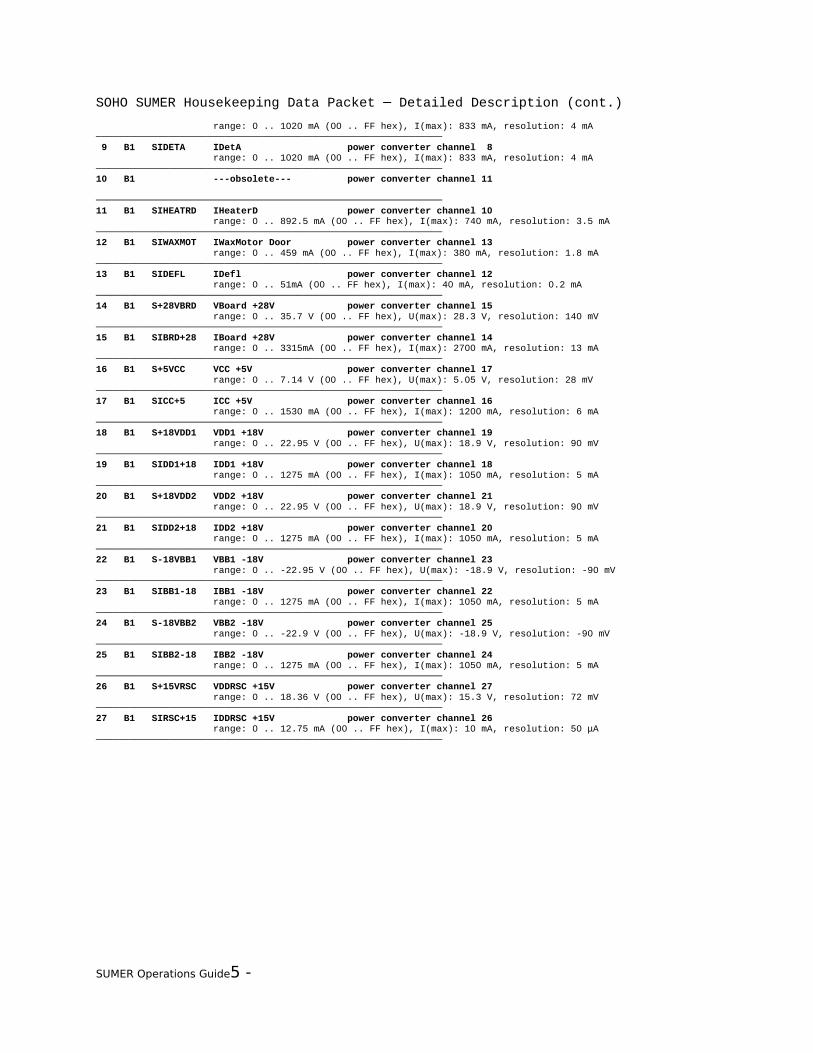
range: 0 .. 1020 mA (00 .. FF hex), I(max): 833 mA, resolution: 4 mA────────────────────────────────────────────────────────────── 9 B1 SIDETA IDetA power converter channel 8 range: 0 .. 1020 mA (00 .. FF hex), I(max): 833 mA, resolution: 4 mA──────────────────────────────────────────────────────────────10 B1 ---obsolete--- power converter channel 11 ──────────────────────────────────────────────────────────────11 B1 SIHEATRD IHeaterD power converter channel 10 range: 0 .. 892.5 mA (00 .. FF hex), I(max): 740 mA, resolution: 3.5 mA──────────────────────────────────────────────────────────────12 B1 SIWAXMOT IWaxMotor Door power converter channel 13 range: 0 .. 459 mA (00 .. FF hex), I(max): 380 mA, resolution: 1.8 mA──────────────────────────────────────────────────────────────13 B1 SIDEFL IDefl power converter channel 12 range: 0 .. 51mA (00 .. FF hex), I(max): 40 mA, resolution: 0.2 mA──────────────────────────────────────────────────────────────14 B1 S+28VBRD VBoard +28V power converter channel 15 range: 0 .. 35.7 V (00 .. FF hex), U(max): 28.3 V, resolution: 140 mV──────────────────────────────────────────────────────────────15 B1 SIBRD+28 IBoard +28V power converter channel 14 range: 0 .. 3315mA (00 .. FF hex), I(max): 2700 mA, resolution: 13 mA──────────────────────────────────────────────────────────────16 B1 S+5VCC VCC +5V power converter channel 17 range: 0 .. 7.14 V (00 .. FF hex), U(max): 5.05 V, resolution: 28 mV──────────────────────────────────────────────────────────────17 B1 SICC+5 ICC +5V power converter channel 16 range: 0 .. 1530 mA (00 .. FF hex), I(max): 1200 mA, resolution: 6 mA──────────────────────────────────────────────────────────────18 B1 S+18VDD1 VDD1 +18V power converter channel 19 range: 0 .. 22.95 V (00 .. FF hex), U(max): 18.9 V, resolution: 90 mV──────────────────────────────────────────────────────────────19 B1 SIDD1+18 IDD1 +18V power converter channel 18 range: 0 .. 1275 mA (00 .. FF hex), I(max): 1050 mA, resolution: 5 mA──────────────────────────────────────────────────────────────20 B1 S+18VDD2 VDD2 +18V power converter channel 21 range: 0 .. 22.95 V (00 .. FF hex), U(max): 18.9 V, resolution: 90 mV──────────────────────────────────────────────────────────────21 B1 SIDD2+18 IDD2 +18V power converter channel 20 range: 0 .. 1275 mA (00 .. FF hex), I(max): 1050 mA, resolution: 5 mA──────────────────────────────────────────────────────────────22 B1 S-18VBB1 VBB1 -18V power converter channel 23 range: 0 .. -22.95 V (00 .. FF hex), U(max): -18.9 V, resolution: -90 mV──────────────────────────────────────────────────────────────23 B1 SIBB1-18 IBB1 -18V power converter channel 22 range: 0 .. 1275 mA (00 .. FF hex), I(max): 1050 mA, resolution: 5 mA──────────────────────────────────────────────────────────────24 B1 S-18VBB2 VBB2 -18V power converter channel 25 range: 0 .. -22.9 V (00 .. FF hex), U(max): -18.9 V, resolution: -90 mV──────────────────────────────────────────────────────────────25 B1 SIBB2-18 IBB2 -18V power converter channel 24 range: 0 .. 1275 mA (00 .. FF hex), I(max): 1050 mA, resolution: 5 mA──────────────────────────────────────────────────────────────26 B1 S+15VRSC VDDRSC +15V power converter channel 27 range: 0 .. 18.36 V (00 .. FF hex), U(max): 15.3 V, resolution: 72 mV──────────────────────────────────────────────────────────────27 B1 SIRSC+15 IDDRSC +15V power converter channel 26 range: 0 .. 12.75 mA (00 .. FF hex), I(max): 10 mA, resolution: 50 μA──────────────────────────────────────────────────────────────
SUMER Operations Guide5 -
SOHO SUMER Housekeeping Data Packet ─ Detailed Description (cont.)
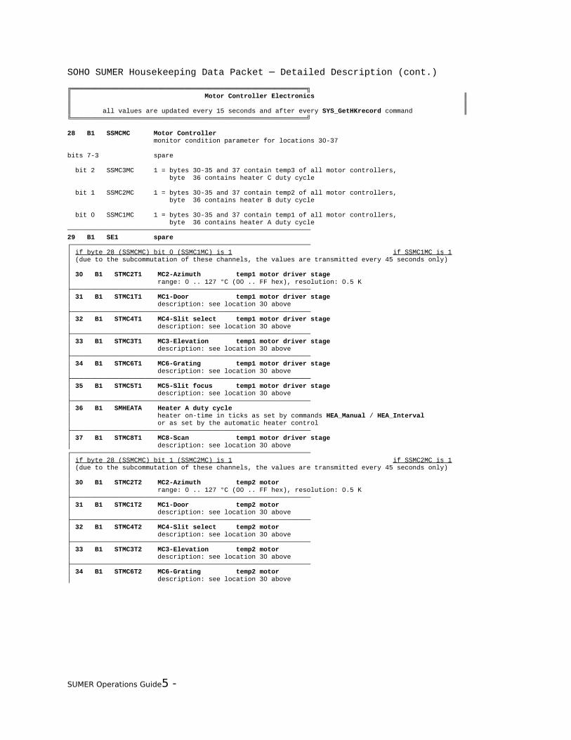
╔════════════════════════════════════════════════════════════╗║ Motor Controller Electronics ║║ ║║ all values are updated every 15 seconds and after every SYS_GetHKrecord command ║╚════════════════════════════════════════════════════════════╝
28 B1 SSMCMC Motor Controller monitor condition parameter for locations 30-37
bits 7-3 spare
bit 2 SSMC3MC 1 = bytes 30-35 and 37 contain temp3 of all motor controllers, byte 36 contains heater C duty cycle
bit 1 SSMC2MC 1 = bytes 30-35 and 37 contain temp2 of all motor controllers, byte 36 contains heater B duty cycle
bit 0 SSMC1MC 1 = bytes 30-35 and 37 contain temp1 of all motor controllers, byte 36 contains heater A duty cycle──────────────────────────────────────────────────────────────29 B1 SE1 spare ┌─────────────────────────────────────────────────────────────│ if byte 28 (SSMCMC) bit 0 (SSMC1MC) is 1 if SSMC1MC is 1│ (due to the subcommutation of these channels, the values are transmitted every 45 seconds only)││ 30 B1 STMC2T1 MC2-Azimuth temp1 motor driver stage│ range: 0 .. 127 °C (00 .. FF hex), resolution: 0.5 K├─────────────────────────────────────────────────────────────│ 31 B1 STMC1T1 MC1-Door temp1 motor driver stage│ description: see location 30 above├─────────────────────────────────────────────────────────────│ 32 B1 STMC4T1 MC4-Slit select temp1 motor driver stage│ description: see location 30 above├─────────────────────────────────────────────────────────────│ 33 B1 STMC3T1 MC3-Elevation temp1 motor driver stage│ description: see location 30 above├─────────────────────────────────────────────────────────────│ 34 B1 STMC6T1 MC6-Grating temp1 motor driver stage│ description: see location 30 above├─────────────────────────────────────────────────────────────│ 35 B1 STMC5T1 MC5-Slit focus temp1 motor driver stage│ description: see location 30 above├─────────────────────────────────────────────────────────────│ 36 B1 SMHEATA Heater A duty cycle│ heater on-time in ticks as set by commands HEA_Manual / HEA_Interval│ or as set by the automatic heater control├─────────────────────────────────────────────────────────────│ 37 B1 STMC8T1 MC8-Scan temp1 motor driver stage│ description: see location 30 above┌─────────────────────────────────────────────────────────────│ if byte 28 (SSMCMC) bit 1 (SSMC2MC) is 1 if SSMC2MC is 1│ (due to the subcommutation of these channels, the values are transmitted every 45 seconds only)││ 30 B1 STMC2T2 MC2-Azimuth temp2 motor│ range: 0 .. 127 °C (00 .. FF hex), resolution: 0.5 K├─────────────────────────────────────────────────────────────│ 31 B1 STMC1T2 MC1-Door temp2 motor│ description: see location 30 above├─────────────────────────────────────────────────────────────│ 32 B1 STMC4T2 MC4-Slit select temp2 motor│ description: see location 30 above├─────────────────────────────────────────────────────────────│ 33 B1 STMC3T2 MC3-Elevation temp2 motor│ description: see location 30 above├─────────────────────────────────────────────────────────────│ 34 B1 STMC6T2 MC6-Grating temp2 motor│ description: see location 30 above
SUMER Operations Guide5 -
SOHO SUMER Housekeeping Data Packet ─ Detailed Description (cont.)
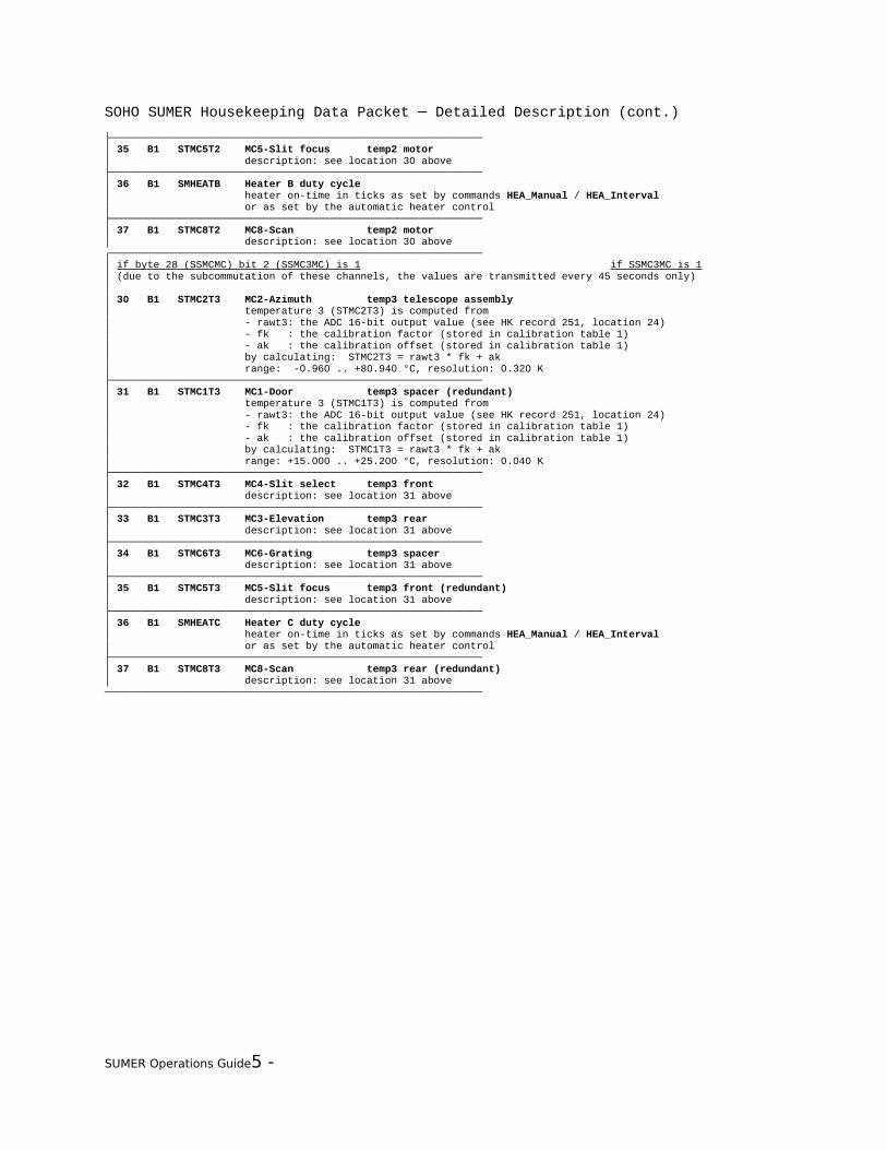
├─────────────────────────────────────────────────────────────│ 35 B1 STMC5T2 MC5-Slit focus temp2 motor│ description: see location 30 above├─────────────────────────────────────────────────────────────│ 36 B1 SMHEATB Heater B duty cycle│ heater on-time in ticks as set by commands HEA_Manual / HEA_Interval│ or as set by the automatic heater control├─────────────────────────────────────────────────────────────│ 37 B1 STMC8T2 MC8-Scan temp2 motor│ description: see location 30 above┌─────────────────────────────────────────────────────────────│ if byte 28 (SSMCMC) bit 2 (SSMC3MC) is 1 if SSMC3MC is 1│ (due to the subcommutation of these channels, the values are transmitted every 45 seconds only)││ 30 B1 STMC2T3 MC2-Azimuth temp3 telescope assembly│ temperature 3 (STMC2T3) is computed from│ - rawt3: the ADC 16-bit output value (see HK record 251, location 24)│ - fk : the calibration factor (stored in calibration table 1)│ - ak : the calibration offset (stored in calibration table 1)│ by calculating: STMC2T3 = rawt3 * fk + ak│ range: -0.960 .. +80.940 °C, resolution: 0.320 K├─────────────────────────────────────────────────────────────│ 31 B1 STMC1T3 MC1-Door temp3 spacer (redundant)│ temperature 3 (STMC1T3) is computed from│ - rawt3: the ADC 16-bit output value (see HK record 251, location 24)│ - fk : the calibration factor (stored in calibration table 1)│ - ak : the calibration offset (stored in calibration table 1)│ by calculating: STMC1T3 = rawt3 * fk + ak│ range: +15.000 .. +25.200 °C, resolution: 0.040 K├─────────────────────────────────────────────────────────────│ 32 B1 STMC4T3 MC4-Slit select temp3 front│ description: see location 31 above├─────────────────────────────────────────────────────────────│ 33 B1 STMC3T3 MC3-Elevation temp3 rear│ description: see location 31 above├─────────────────────────────────────────────────────────────│ 34 B1 STMC6T3 MC6-Grating temp3 spacer│ description: see location 31 above├─────────────────────────────────────────────────────────────│ 35 B1 STMC5T3 MC5-Slit focus temp3 front (redundant)│ description: see location 31 above├─────────────────────────────────────────────────────────────│ 36 B1 SMHEATC Heater C duty cycle│ heater on-time in ticks as set by commands HEA_Manual / HEA_Interval│ or as set by the automatic heater control├─────────────────────────────────────────────────────────────│ 37 B1 STMC8T3 MC8-Scan temp3 rear (redundant)│ description: see location 31 above──────────────────────────────────────────────────────────────
SUMER Operations Guide5 -

SOHO SUMER Housekeeping Data Packet ─ Detailed Description (cont.)
╔════════════════════════════════════════════════════════════╗║ DPU Interface ║║ ║║ all values are updated every 15 seconds ║╚════════════════════════════════════════════════════════════╝
38 B1 STDPUCU1 HK2 (temperature DPU-RAM CU1) Channel 2 range: -30 .. +97.5 °C, resolution: 0.5 K──────────────────────────────────────────────────────────────39 B1 STDPUDCC HK1 (temperature DC/DC converter) Channel 1 range: -30 .. +97.5 °C, resolution: 0.5 K──────────────────────────────────────────────────────────────40 B1 STDPUEBX HK4 (temperature E-Box) Channel 4 range: -30 .. +97.5 °C, resolution: 0.5 K──────────────────────────────────────────────────────────────41 B1 STDPUCU2 HK3 (temperature DPU-RAM CU2) Channel 3 range: -30 .. +97.5 °C, resolution: 0.5 K──────────────────────────────────────────────────────────────42 B1 SIDPU+5V DC/DC converter +5V/current Channel 6 range: 0 .. 4.98 A, resolution: 19.53 mA──────────────────────────────────────────────────────────────43 B1 S+5VDPU DC/DC converter +5V/voltage Channel 5 range: 0 .. 9.96 V, resolution: 39.06 mV──────────────────────────────────────────────────────────────
SUMER Operations Guide5 -
SOHO SUMER Housekeeping Data Packet ─ Detailed Description (cont.)
╔════════════════════════════════════════════════════════════╗║ ECP / SPU ║║ ║║ all values are updated every second and after every SYS command concerning these values ║╚════════════════════════════════════════════════════════════╝
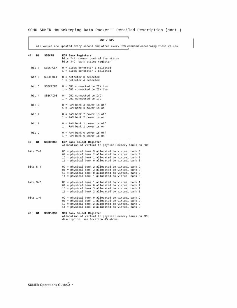
44 B1 SSECPB ECP Bank Registers bits 7-4: common control bus status bits 3-0: bank status register
bit 7 SSECPCLK 0 = clock generator 1 selected 1 = clock generator 2 selected
bit 6 SSECPDET 0 = detector B selected 1 = detector A selected
bit 5 SSECPIMB 0 = CU1 connected to IIM bus 1 = CU2 connected to IIM bus
bit 4 SSECPIOS 0 = CU2 connected to I/O 1 = CU1 connected to I/O
bit 3 0 = RAM bank 3 power is off 1 = RAM bank 3 power is on
bit 2 0 = RAM bank 2 power is off 1 = RAM bank 2 power is on
bit 1 0 = RAM bank 1 power is off 1 = RAM bank 1 power is on
bit 0 0 = RAM bank 0 power is off 1 = RAM bank 0 power is on──────────────────────────────────────────────────────────────45 B1 SSECPBSR ECP Bank Select Register Allocation of virtual to physical memory banks on ECP
bits 7-6 00 = physical bank 3 allocated to virtual bank 3 01 = physical bank 2 allocated to virtual bank 3 10 = physical bank 1 allocated to virtual bank 3 11 = physical bank 0 allocated to virtual bank 3
bits 5-4 00 = physical bank 2 allocated to virtual bank 2 01 = physical bank 3 allocated to virtual bank 2 10 = physical bank 0 allocated to virtual bank 2 11 = physical bank 1 allocated to virtual bank 2
bits 3-2 00 = physical bank 1 allocated to virtual bank 1 01 = physical bank 0 allocated to virtual bank 1 10 = physical bank 3 allocated to virtual bank 1 11 = physical bank 2 allocated to virtual bank 1
bits 1-0 00 = physical bank 0 allocated to virtual bank 0 01 = physical bank 1 allocated to virtual bank 0 10 = physical bank 2 allocated to virtual bank 0 11 = physical bank 3 allocated to virtual bank 0──────────────────────────────────────────────────────────────46 B1 SSSPUBSR SPU Bank Select Register Allocation of virtual to physical memory banks on SPU description: see location 45 above
SUMER Operations Guide5 -

SOHO SUMER Housekeeping Data Packet ─ Detailed Description (cont.)
──────────────────────────────────────────────────────────────47 B1 SSECPERR ECP Error Status Register bits 7-4: powerfail at physical memory banks bits 3-0: double bit errors in data words
bit 7 0 = no powerfail at physical memory bank 3 1 = powerfail at physical memory bank 3
bit 6 0 = no powerfail at physical memory bank 2 1 = powerfail at physical memory bank 2
bit 5 0 = no powerfail at physical memory bank 1 1 = powerfail at physical memory bank 1
bit 4 0 = no powerfail at physical memory bank 0 1 = powerfail at physical memory bank 0
bit 3 0 = no error in data word D16-D31 1 = double bit error in data word D16-D31
bit 2 0 = no error in data word D00-D15 1 = double bit error in data word D00-D15
bit 1 0 = no error in data word D16-D31 1 = double bit error in data word D16-D31
bit 0 0 = no error in data word D00-D15 1 = double bit error in data word D00-D15──────────────────────────────────────────────────────────────48 B1 SSSPUERR SPU Error Status Register bits 7-4: powerfail at physical memory banks bits 3-0: double bit errors in data words description: see location 47 above──────────────────────────────────────────────────────────────49 B1 SSSPUB SPU Bank Registers bits 7-4: spare bits 3-0: SSSPUB bank status register
bits 7-4 spare
bit 3 0 = RAM bank 3 power is off 1 = RAM bank 3 power is on
bit 2 0 = RAM bank 2 power is off 1 = RAM bank 2 power is on
bit 1 0 = RAM bank 1 power is off 1 = RAM bank 1 power is on
bit 0 0 = RAM bank 0 power is off 1 = RAM bank 0 power is on──────────────────────────────────────────────────────────────
SUMER Operations Guide5 -
SOHO SUMER Housekeeping Data Packet ─ Detailed Description (cont.)
╔════════════════════════════════════════════════════════════╗║ Config Register / Boot Controller ║║ ║║ all values are updated every 15 seconds, ║║ SSCU1 and SSCU2 are updated after every write access to the CU1 and CU2 config registers ║╚════════════════════════════════════════════════════════════╝
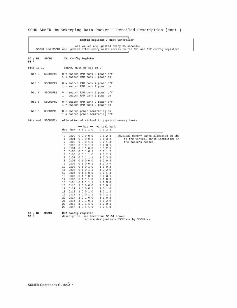
50 ┐ B2 SSCU1 CU1 Config Register51 ┘
bits 15-10 spare, must be set to 0
bit 9 SSCU1PR3 0 = switch RAM bank 3 power off 1 = switch RAM bank 3 power on
bit 8 SSCU1PR2 0 = switch RAM bank 2 power off 1 = switch RAM bank 2 power on
bit 7 SSCU1PR1 0 = switch RAM bank 1 power off 1 = switch RAM bank 1 power on
bit 6 SSCU1PR0 0 = switch RAM bank 0 power off 1 = switch RAM bank 0 power on
bit 5 SSCU1PM 0 = switch power monitoring on 1 = switch power monitoring off
bits 4-0 SSCU1P2V Allocation of virtual to physical memory banks
── bit ── virtual bank dec hex 4 3 2 1 0 0 1 2 3 ────────────────────────────────────────────────────────────── 0 0x00 0 0 0 0 0 0 1 2 3 ┐ physical memory banks allocated to the 1 0x01 0 0 0 0 1 0 1 3 2 │ to the virtual banks identified in 2 0x02 0 0 0 1 0 0 2 1 3 │ the table's header 3 0x03 0 0 0 1 1 0 2 3 1 │ 4 0x04 0 0 1 0 0 0 3 2 1 │ 5 0x05 0 0 1 0 1 0 3 1 2 │ 6 0x06 0 0 1 1 0 1 0 2 3 │ 7 0x07 0 0 1 1 1 1 0 3 2 │ 8 0x08 0 1 0 0 0 1 2 0 3 │ 9 0x09 0 1 0 0 1 1 2 3 0 │ 10 0x0a 0 1 0 1 0 1 3 0 2 │ 11 0x0b 0 1 0 1 1 1 3 2 0 │ 12 0x0c 0 1 1 0 0 2 0 1 3 │ 13 0x0d 0 1 1 0 1 2 0 3 1 │ 14 0x0e 0 1 1 1 0 2 1 0 3 │ 15 0x0f 0 1 1 1 1 2 1 3 0 │ 16 0x10 1 0 0 0 0 2 3 0 1 │ 17 0x11 1 0 0 0 1 2 3 1 0 │ 18 0x12 1 0 0 1 0 3 0 1 2 │ 19 0x13 1 0 0 1 1 3 0 2 1 │ 20 0x14 1 0 1 0 0 3 1 0 2 │ 21 0x15 1 0 1 0 1 3 1 2 0 │ 22 0x16 1 0 1 1 0 3 2 0 1 │ 23 0x17 1 0 1 1 1 3 2 1 0 ┘──────────────────────────────────────────────────────────────52 ┐ B2 SSCU2 CU2 config register53 ┘ description: see locations 50-51 above replace designations SSCU1xxx by SSCU2xxx
SUMER Operations Guide5 -

SOHO SUMER Housekeeping Data Packet ─ Detailed Description (cont.)
──────────────────────────────────────────────────────────────54 ┐ B2 SSBCREG Boot Controller Configuration Register Actual BC55 ┘ (value does not change after booting)
bit 15 CU1 latch up detected in bank 3 1 = yes, 0 = no bit 14 CU1 latch up detected in bank 2 1 = yes, 0 = no bit 13 CU1 latch up detected in bank 1 1 = yes, 0 = no bit 12 CU1 latch up detected in bank 0 1 = yes, 0 = no bit 11 CU2 latch up detected in bank 3 1 = yes, 0 = no bit 10 CU2 latch up detected in bank 2 1 = yes, 0 = no bit 9 CU2 latch up detected in bank 1 1 = yes, 0 = no bit 8 CU2 latch up detected in bank 0 1 = yes, 0 = no bit 7 always 0 bit 6 SSBCBSRC boot from: 1 = EPROM, 0 = link bit 5 SSBCRSRC reset source: 1 = any other reset, 0 = power on reset bit 4 SSBCCMD 1 = commanded configuration, 0 = automatic configuration
bits 3-2 SSBCMODE boot controller mode 00 = normal mode, CU1 is ECP 01 = normal mode, CU2 is ECP 10 = emergency mode on CU1 11 = emergency mode on CU2
bit 1 SSBCCLCK clock generator (CG): 1 = CG2, 0 = CG1 bit 0 SSBC boot controller (BC): 1 = BC2, 0 = BC1──────────────────────────────────────────────────────────────56 ┐ B2 SSBCVAL boot controller configuration value actual BC57 ┘ (value does not change after booting)
bit 15 always 0 bit 14 always 0 bit 13 SSCU2BNK CU2 on-board RAM test failed 1 = yes, 0 = no bit 12 SSCU1BNK CU1 on-board RAM test failed 1 = yes, 0 = no bit 11 SSCU2CU1 linktest CU2 CU1 failed 1 = yes, 0 = no bit 10 SSCU2RAM on-board RAM test CU2 failed 1 = yes, 0 = no bit 9 SSCU2MEM peek/poke memtest CU2 failed 1 = yes, 0 = no bit 8 SSCU2LNK link CU2 bad 1 = yes, 0 = no bit 7 SSCU1CU2 link test CU1 CU2 failed 1 = yes, 0 = no bit 6 SSCU1RAM on-board RAM test CU1 failed 1 = yes, 0 = no bit 5 SSCU1MEM peek/poke memtest CU1 failed 1 = yes, 0 = no bit 4 SSCU1LNK link CU1 bad 1 = yes, 0 = no bit 3 SSEMRGSW EPROM-CRC emergency SW failed 1 = yes, 0 = no bit 2 SSSPUSW EPROM-CRC SPU SW failed 1 = yes, 0 = no bit 1 SSECPSW EPROM-CRC ECP SW failed 1 = yes, 0 = no bit 0 SSBCSW EPROM-CRC BC SW failed 1 = yes, 0 = no──────────────────────────────────────────────────────────────
SUMER Operations Guide5 -

╔════════════════════════════════════════════════════════════╗║ Spacecraft Interface ║║ ║║ all values are updated every 15 seconds, volatile values whenever they change ║╚════════════════════════════════════════════════════════════╝
58 B1 SSSCSTAT inter-instrument mode / nonvalid TC block counter
bit 7 spare bits 6-5 SSIIDBIT inter-instrument mode bit: 00 = standby, 01 = master, 10 = receiver bit 4 spare bits 3-0 SSTCNONV nonvalid TC block counter (0 .. 15)──────────────────────────────────────────────────────────────59 B1 SSTCCNT TC block counter 0 .. 255, wraps over to 0──────────────────────────────────────────────────────────────60 B1 Toggle flag byte
bit 0 SSTCTOGN toggle flag bit, range 0 .. 1──────────────────────────────────────────────────────────────61 B1 SSEVCNT valid solar event coordinates counter 0 .. 255, wraps over to 0, is reset to 0 in stand-by mode──────────────────────────────────────────────────────────────62 .. 69: 4*B2 SSTMREPF TM reporting file**************************************************************************************************62 ┐ B2 SSTMREP0 TM reporting file 063 ┘
bits 15-5 bits 10-0 of the respective MLA-word
bits 4-0 error code: 01000 = block command length is not between 2 and 32 words 00100 = block command identifier is not valid 10001 = checksum is not correct 00010 = block command destination is not correct 10010 = new MLA received before the last word of the current block command 10100 = delay > 1 s occurred between the reception of the MLA header and the following MLB word or between two successive words──────────────────────────────────────────────────────────────64 ┐ B2 SSTMREP1 TM reporting file 165 ┘ description: see locations 62-63 above──────────────────────────────────────────────────────────────66 ┐ B2 SSTMREP2 TM reporting file 267 ┘ description: see locations 62-63 above──────────────────────────────────────────────────────────────68 ┐ B2 SSTMREP3 TM reporting file 369 ┘ description: see locations 62-63 above──────────────────────────────────────────────────────────────70 .. 73: 2*B2 SSIIDMM inter-instrument master message**************************************************************************************************70 ┐ B2 master ID and solar coordinate y71 ┘
bit 15 validity bit: 1 = invalid, 0 = validbits 14-11 master ID bit 10 always 0bits 9-0 solar coordinate y, resolution: 2 arcsec──────────────────────────────────────────────────────────────72 ┐ B2 solar event ID and solar coordinate z73 ┘
bit 15 validity bit: 1 = invalid, 0 = validbits 14-11 solar event ID bit 10 always 1bits 9-0 solar coordinate z, resolution: 2 arcsec──────────────────────────────────────────────────────────────
SUMER Operations Guide5 -

SUMER HK Record 250 ─ Voltages and Currents (cont.)
╔════════════════════════════════════════════════════════════╗║ Motor Controller Electronics (cont.) ║║ ║║ all values are updated every 15 seconds and after every SYS_GetHKrecord command, ║║ the status values after every command addressing a motor controller ║╚════════════════════════════════════════════════════════════╝
74 B1 S-15MC1 MC1-Door -15V range: 0 .. -20.40 V (00 .. FF hex), resolution: 80 mV──────────────────────────────────────────────────────────────75 B1 S+15MC1 MC1-Door +15V range: 0 .. 20.40 V (00 .. FF hex), resolution: 80 mV──────────────────────────────────────────────────────────────76 ┐ B2 SSMC1POS MC1-Door encoder value77 ┘──────────────────────────────────────────────────────────────78 B1 S+5MC1 MC1-Door +5V range: 0 .. 10.20 V (00 .. FF hex), resolution: 40 mV──────────────────────────────────────────────────────────────79 B1 SSMC1 MC1-Door status
bit 7 SSMC1ERR 1 = error bit 6 SSMC1CMD 1 = command executed bit 5 SSMC1EPO 1 = encoder power off bit 4 SSMC1ETO 1 = encoder timeout bit 3 SSMC1RES 1 = reset bit 2 SSMC1ADC 1 = ADC power offbits 1-0 spare ──────────────────────────────────────────────────────────────80 B1 S-15MC2 MC2-Azimuth -15V range: 0 .. -20.40 V (00 .. FF hex), resolution: 80 mV──────────────────────────────────────────────────────────────81 B1 S+15MC2 MC2-Azimuth +15V range: 0 .. 20.40 V (00 .. FF hex), resolution: 80 mV──────────────────────────────────────────────────────────────82 ┐ B2 SSMC2POS MC2-Azimuth encoder value83 ┘──────────────────────────────────────────────────────────────84 B1 S+5MC2 MC2-Azimuth +5V range: 0 .. 10.20 V (00 .. FF hex), resolution: 40 mV──────────────────────────────────────────────────────────────85 B1 SSMC2 MC2-Azimuth status
bit 7 SSMC2ERR 1 = error bit 6 SSMC2CMD 1 = command executed bit 5 SSMC2EPO 1 = encoder power off bit 4 SSMC2ETO 1 = encoder timeout bit 3 SSMC2RES 1 = reset bit 2 SSMC2ADC 1 = ADC power offbits 1-0 spare ──────────────────────────────────────────────────────────────86 B1 S-15MC3 MC3-Elevation -15V range: 0 .. -20.40 V (00 .. FF hex), resolution: 80 mV──────────────────────────────────────────────────────────────87 B1 S+15MC3 MC3-Elevation +15V range: 0 .. 20.40 V (00 .. FF hex), resolution: 80 mV──────────────────────────────────────────────────────────────88 ┐ B2 SSMC3POS MC3-Elevation encoder value89 ┘──────────────────────────────────────────────────────────────90 B1 S+5MC3 MC3-Elevation +5V range: 0 .. 10.20 V (00 .. FF hex), resolution: 40 mV
SUMER Operations Guide5 -

SUMER HK Record 250 ─ Voltages and Currents (cont.)
──────────────────────────────────────────────────────────────91 B1 SSMC3 MC3-Elevation status
bit 7 SSMC3ERR 1 = error bit 6 SSMC3CMD 1 = command executed bit 5 SSMC3EPO 1 = encoder power off bit 4 SSMC3ETO 1 = encoder timeout bit 3 SSMC3RES 1 = reset bit 2 SSMC3ADC 1 = ADC power offbits 1-0 spare ──────────────────────────────────────────────────────────────92 B1 S-15MC4 MC4-Slit select -15V range: 0 .. -20.40 V (00 .. FF hex), resolution: 80 mV──────────────────────────────────────────────────────────────93 B1 S+15MC4 MC4-Slit select +15V range: 0 .. 20.40 V (00 .. FF hex), resolution: 80 mV──────────────────────────────────────────────────────────────94 ┐ B2 SSMC4POS MC4-Slit select encoder value95 ┘──────────────────────────────────────────────────────────────96 B1 S+5MC4 MC4-Slit select +5V range: 0 .. 10.20 V (00 .. FF hex), resolution: 40 mV──────────────────────────────────────────────────────────────97 B1 SSMC4 MC4-Slit select status
bit 7 SSMC4ERR 1 = error bit 6 SSMC4CMD 1 = command executed bit 5 SSMC4EPO 1 = encoder power off bit 4 SSMC4ETO 1 = encoder timeout bit 3 SSMC4RES 1 = reset bit 2 SSMC4ADC 1 = ADC power offbits 1-0 spare ──────────────────────────────────────────────────────────────98 B1 S-15MC5 MC5-Slit focus -15V range: 0 .. -20.40 V (00 .. FF hex), resolution: 80 mV──────────────────────────────────────────────────────────────99 B1 S+15MC5 MC5-Slit focus +15V range: 0 .. 20.40 V (00 .. FF hex), resolution: 80 mV──────────────────────────────────────────────────────────────100 ┐ B2 SSMC5POS MC5-Slit focus encoder value101 ┘──────────────────────────────────────────────────────────────102 B1 S+5MC5 MC5-Slit focus +5V range: 0 .. 10.20 V (00 .. FF hex), resolution: 40 mV──────────────────────────────────────────────────────────────103 B1 SSMC5 MC5-Slit focus status
bit 7 SSMC5ERR 1 = error bit 6 SSMC5CMD 1 = command executed bit 5 SSMC5EPO 1 = encoder power off bit 4 SSMC5ETO 1 = encoder timeout bit 3 SSMC5RES 1 = reset bit 2 SSMC5ADC 1 = ADC power offbits 1-0 spare ──────────────────────────────────────────────────────────────104 B1 S-15MC6 MC6-Grating -15V range: 0 .. -20.40 V (00 .. FF hex), resolution: 80 mV──────────────────────────────────────────────────────────────105 B1 S+15MC6 MC6-Grating +15V range: 0 .. 20.40 V (00 .. FF hex), resolution: 80 mV──────────────────────────────────────────────────────────────106 ┐ B2 SSMC6POS MC6-Grating encoder value107 ┘──────────────────────────────────────────────────────────────108 B1 S+5MC6 MC6-Grating +5V range: 0 .. 10.20 V (00 .. FF hex), resolution: 40 mV
SUMER Operations Guide5 -

──────────────────────────────────────────────────────────────109 B1 SSMC6 MC6-Grating status
bit 7 SSMC6ERR 1 = error bit 6 SSMC6CMD 1 = command executed bit 5 SSMC6EPO 1 = encoder power off bit 4 SSMC6ETO 1 = encoder timeout bit 3 SSMC6RES 1 = reset bit 2 SSMC6ADC 1 = ADC power offbits 1-0 spare ──────────────────────────────────────────────────────────────110 B1 S-15MC8 MC8-Scan -15V range: 0 .. -20.40 V (00 .. FF hex), resolution: 80 mV──────────────────────────────────────────────────────────────111 B1 S+15MC8 MC8-Scan +15V range: 0 .. 20.40 V (00 .. FF hex), resolution: 80 mV──────────────────────────────────────────────────────────────112 ┐ B2 SSMC8POS MC8-Scan IAS encoder value113 ┘ bits 15-0 only, bits 17-16 in bits 1-0 of location 115 (MC8-Scan status)──────────────────────────────────────────────────────────────114 B1 S+5MC8 MC8-Scan +5V range: 0 .. 10.20 V (00 .. FF hex), resolution: 40 mV──────────────────────────────────────────────────────────────115 B1 SSMC8 MC8-Scan status
bit 7 SSMC8ERR 1 = error bit 6 SSMC8CMD 1 = command executed bit 5 SSMC8EPO 1 = encoder power off bit 4 SSMC8ETO 1 = encoder timeout bit 3 SSMC8RES 1 = reset bit 2 SSMC8ADC 1 = ADC power offbits 1-0 SSMC8IAS 1 = IAS encoder bits 17 and 16 (bits 15-0 in location 112-113)──────────────────────────────────────────────────────────────116 B1 spare 117 B1 SMHEAMOD Heater mode118 B1 SSHEATKS Heater ticks119 B1 spare──────────────────────────────────────────────────────────────
SUMER Operations Guide5 -
SUMER HK Record 251 ─ Motor Controller Data (cont.)
╔════════════════════════════════════════════════════════════╗║ Emergency Switch-Off and -On ║║ ║║ all values are updated every 15 seconds ║╚════════════════════════════════════════════════════════════╝
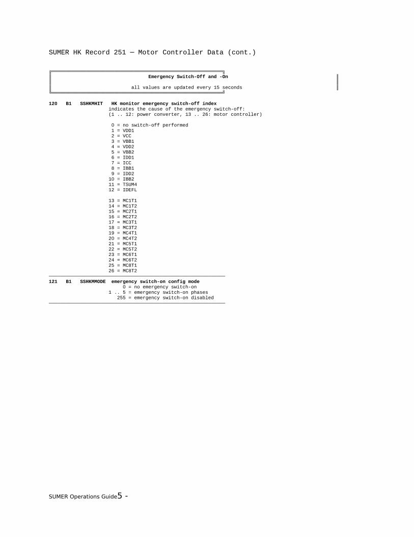
120 B1 SSHKMHIT HK monitor emergency switch-off index indicates the cause of the emergency switch-off: (1 .. 12: power converter, 13 .. 26: motor controller)
0 = no switch-off performed 1 = VDD1 2 = VCC 3 = VBB1 4 = VDD2 5 = VBB2 6 = IDD1 7 = ICC 8 = IBB1 9 = IDD2 10 = IBB2 11 = TSUM4 12 = IDEFL
13 = MC1T1 14 = MC1T2 15 = MC2T1 16 = MC2T2 17 = MC3T1 18 = MC3T2 19 = MC4T1 20 = MC4T2 21 = MC5T1 22 = MC5T2 23 = MC6T1 24 = MC6T2 25 = MC8T1 26 = MC8T2──────────────────────────────────────────────────────────────121 B1 SSHKMMODE emergency switch-on config mode 0 = no emergency switch-on 1 .. 5 = emergency switch-on phases 255 = emergency switch-on disabled──────────────────────────────────────────────────────────────
SUMER Operations Guide5 -

╔════════════════════════════════════════════════════════════╗║ Rear Slit Camera ║║ ║║ the value is updated after every RSC command ║╚════════════════════════════════════════════════════════════╝
122 B1 SE3 spare ──────────────────────────────────────────────────────────────123 I1 SSRSC result from level 4 command RSC_ReadImage
SSRSCANS 0 = ANSOK : answer ok SSRSCCF -3 = COMERR: communication error SSRSCPER -5 = PARERR: parameter range error SSRSCTOE -7 = CTOERR: timeout errror SSRSCPWE -11 = POWERR: power alert -13 = RSCTI1: RSC time out on first half full flag after power on -14 = RSCTI2: RSC time out on read out
(SSRSCPXE -12 = PIXERR: first pixel error -- obsolete --)──────────────────────────────────────────────────────────────
SUMER Operations Guide5 -

╔════════════════════════════════════════════════════════════╗║ Image Integration Memories ║║ ║║ all values are updated every second and after every IIM command ║╚════════════════════════════════════════════════════════════╝
124 ┐ B2 SSIIM IIM status register125 ┘
bit 15 SSIIMCRM 1 = clear DPU channel 0 = random access to DPU channel bit 14 SSIIMSCR 1 = selected channel ready 0 = selected channel not ready bit 13 SSIIMPSB 1 = power status ch B on 0 = power status ch B off bit 12 SSIIMPSA 1 = power status ch A on 0 = power status ch A off bit 11 SSIIMDEB 1 = double bit error ch B 0 = no double bit errors ch B bit 10 SSIIMSEB 1 = single bit error ch B 0 = no single bit errors ch B bit 9 SSIIMDEA 1 = double bit error ch A 0 = no double bit errors ch A bit 8 SSIIMSEA 1 = single bit error ch A 0 = no single bit errors ch A bit 7 SSIIMLSB 1 = latch up strobe ch B (low threshold) 0 = high LU trigger threshold ch B bit 6 SSIIMLSA 1 = latch up strobe ch A (low threshold) 0 = high LU trigger threshold ch A bit 5 SSIIMPCB 1 = power command ch B on 0 = power command ch B off bit 4 SSIIMPCA 1 = power command ch A on 0 = power command ch A off bit 3 SSIIMSTP 1 = set power 0 = hold power status bit 2 SSIIMCHS 1 = channel B to DPU 0 = channel A to DPU bit 1 SSIIMING 1 = input gate open 0 = input gate closed bit 0 SSIIMACR 1 = auto clear on 0 = auto clear off──────────────────────────────────────────────────────────────126 B1 SE 7 spare ──────────────────────────────────────────────────────────────127 I1 SSIIMRES result from level 4 commands IIMxxxx
SSIIMANS 0 = ANSOK : answer ok SSIIMPER -5 = PARERR: parameter range error──────────────────────────────────────────────────────────────
SUMER Operations Guide5 -

SUMER HK Record 255 ─ Cycle Time 1 s (cont.)
╔════════════════════════════════════════════════════════════╗║ Detector Electronics ║║ (changed due to new detector model) ║║ ║║ all values are updated every 15 seconds ║╚════════════════════════════════════════════════════════════╝
128...175 48*B1 SYXDL XDL data channels128 12*B1 SYXPHAX XDL X PHA data (2nd byte in 132, 3rd in 136 etc.)130 12*B1 SYXPHAY XDL Y PHA data (2nd byte in 134, 3rd in 138 etc.*******************************************************************************************************128 B1 SYXPHAX XDL X PHA Data_______________________________________________________________________________________________________129 B1 SIXLVPI LVPS Current Monitor 0.113 W * SIXLVPI_______________________________________________________________________________________________________130 B1 SYXPHAY XDL Y PHA Data_______________________________________________________________________________________________________131 B1 SSXACCEL Post Accel HV Status N = 0.044 * SSXPOST - 0.156 0<N<1 for normal operation, when on_______________________________________________________________________________________________________132 B1 SYXPHAX XDL X PHA Data_______________________________________________________________________________________________________133 B1 S+XMCPV MCP Voltage Monitor -22.18 V * S+XMCPV_______________________________________________________________________________________________________134 B1 SYXPHAY XDL Y PHA Data_______________________________________________________________________________________________________135 B1 SIXMCPI MCP Current Monitor 0.98 * SIXMCPI - 0.668 * S+XMCPV + 81.02 (uA)_______________________________________________________________________________________________________136 B1 SYXPHAX XDL X PHA Data_______________________________________________________________________________________________________137 B1 S+XTDC5 +5V Monitor for TDC Box supply 0.0366V * S+XTDC5_______________________________________________________________________________________________________138 B1 SYXPHAY XDL Y PHA Data_______________________________________________________________________________________________________139 B1 S-XTDC5 -5V Monitor for TDC Box supply 0.0816V * S-XTDC5 - 15.826_______________________________________________________________________________________________________140 B1 SYXPHAX XDL X PHA Data_______________________________________________________________________________________________________141 B1 S+XTDC10 +10V Monitor for TDC Box supply 0.088V * S+XTDC10_______________________________________________________________________________________________________142 B1 SYXPHAY XDL Y PHA Data_______________________________________________________________________________________________________143 B1 S-XTDC15 -15V Monitor for TDC Box supply 0.202V * S-XTDC15 - 46.49_______________________________________________________________________________________________________144 B1 SYXPHAX XDL X PHA Data_______________________________________________________________________________________________________145 B1 S+XMON13 +13V Monitor for Monitor Box supply 0.0853V * S+XMON13_______________________________________________________________________________________________________146 B1 SYXPHAY XDL Y PHA Data_______________________________________________________________________________________________________147 B1 S-XMON13 -13V Monitor for Monitor Box supply 0.178V * S-XMON13 - 40.28_______________________________________________________________________________________________________148 B1 SYXPHAX XDL X PHA Data_______________________________________________________________________________________________________149 B1 S+XMON5 +5V Monitor for Monitor Box supply 0.0392V * S+XMON5 _______________________________________________________________________________________________________150 B1 SYXPHAY XDL Y PHA Data_______________________________________________________________________________________________________151 B1 S+XTIMX X Timing Threshold 0.0196V * S+XTIMX _______________________________________________________________________________________________________152 B1 SYXPHAX XDL X PHA Data_______________________________________________________________________________________________________
SUMER Operations Guide5 -

SUMER HK Record 255 ─ Cycle Time 1 s (cont.)
153 B1 S+XCHX X Charge Threshold 0.0196V * S+XCHX _______________________________________________________________________________________________________154 B1 SYXPHAY XDL Y PHA Data_______________________________________________________________________________________________________155 B1 S+XTIMY Y Timing Threshold 0.0196V * S+XTIMY _______________________________________________________________________________________________________156 B1 SYXPHAX XDL X PHA Data_______________________________________________________________________________________________________157 B1 S+XCHY Y Charge Threshold 0.0196V * S+XCHY_______________________________________________________________________________________________________158 B1 SYXPHAY XDL Y PHA Data_______________________________________________________________________________________________________159 B1 STXDL Temperature Channel (defined by SSXSID) -40deg=250 30deg=144 -20deg=237 40deg=119 0 deg=214 50deg=95 10deg=195 60deg=73 20deg=170 70deg=56 80deg=44 _______________________________________________________________________________________________________160 B1 SYXPHAX XDL X PHA Data_______________________________________________________________________________________________________161 B1 SSXDEF (contains SSXSID)
bit 7 SSXSTIM Stim pulser, 1=enabled, 0=disabled bit 3 SSXCERR If 1=Cmd error during last 8 readout cycles bit 6-4 SSXSID Defines content of STXDL and SSXCECHO bit 2-0 SSXSID Defines content of STXDL and SSXCECHO (redundant) conditioned| Content of the channels by content | of SSXSID| SSXDECHO | STXDL ----|-------------------------------------------------------- 111 | SSXCUTY Y Charge Up Thresh | S+XUTY Y UP Thresh 110 | SSXCUTX X Charge Up Thresh | S+XUTX X Up Thresh 101 | SSXHVON HV On/Off | STXMONBX Monitor Box 100 | SSXHVEN HV Enable/Disable | STXTDCBX TDC Box 011 | SSXCTY Y Charge Threshold | STXDET Detector 010 | SSXCTX X Charge Threshold | STXHVPSB HVPS Box 001 | SSXTTY Y Time Threshold | STXAMPBX Amp Box 000 | SSXTTX X Time Threshold | STXLVPSB LVPS Box_______________________________________________________________________________________________________162 B1 SYXPHAY XDL Y PHA Data_______________________________________________________________________________________________________163 B1 SSXCECHO Command Echo (defined by SSXSID)_______________________________________________________________________________________________________164 B1 SYXPHAX XDL X PHA Data_______________________________________________________________________________________________________165 B1 SSXHVCMD HV Command Level (command addr 11)_______________________________________________________________________________________________________166 B1 SYXPHAY XDL Y PHA Data_______________________________________________________________________________________________________167 B1 SSXHVSTA HV Status Register
D7, D3: 1=Cmd HV on, 0=Cmd HV off D6, D2: 1=Cmd Enabled, 0=Cmd disabled D5, D1: 1=Plug Enabled, 0=Plug disabled D4, D0; 1=HVPS is on (programmed voltage) 0=HVPS is off (0V) bit 7 SSXCHVON (1) CMD HV on bit 3 SSXCHVON (1) CMD HV on (redundant) bit 6 SSXCEN (1) CMD Enabled bit 2 SSXCEN (1) CMD Enabled (redundant) bit 5 SSXPLUG (1) Plug Enabled bit 1 SSXPLUG (1) Plug Enabled (redundant) bit 4 SSXHVPS (1) HVPS is on bit 0 SSXHVPS (1) HVPS is on (redundant)_______________________________________________________________________________________________________168 B1 SYXPHAX XDL X PHA Data_______________________________________________________________________________________________________
SUMER Operations Guide5 -

SUMER Image Record Header Block ─ Synopsis (cont.)
169 B1 SSXMXEV X Event Counter MSByte_______________________________________________________________________________________________________170 B1 SYXPHAY XDL Y PHA Data_______________________________________________________________________________________________________171 B1 SSXLXEV X Event Counter LSByte_______________________________________________________________________________________________________172 B1 SYXPHAX XDL X PHA Data_______________________________________________________________________________________________________173 B1 SSXMYEV Y Event Counter MSByte_______________________________________________________________________________________________________174 B1 SYXPHAY XDL Y PHA Data_______________________________________________________________________________________________________175 B1 SSXLYEV Y Event Counter LSByte******************************************************************************************************* B2 SSXXEV X Event Counter SSXMXEV * 255 + SSXLXEV B2 SSXYEV Y Event Counter SSXMYEV * 255 + SSXLYEV_______________________________________________________________________________________________________
SUMER Operations Guide5 -

╔════════════════════════════════════════════════════════════╗║ DPU Software ║║ ║║ SKAFTRES is updated after every AFT command ║║ SSCONF00 .. SSCONF71 are updated after every SYS_Config command ║║ SKEXPSTA is updated whenever level 2 and 3 commands start and end ║╚════════════════════════════════════════════════════════════╝
176 ┐ B2 SKAFTRES AFT result (transmitted after the AFT has ended)177 ┘ The end of an AFT is indicated by the transition of the SKOPERAT mode bit from 1 to 0.
bit 15 SKAFTDET Detector 0 = success, 1 = error bit 14 SKAFTM8 MC8-Scan 0 = success, 1 = error bit 13 SKAFTM6 MC6-Grating 0 = success, 1 = error bit 12 SKAFTM5 MC5-Slit focus 0 = success, 1 = error bit 11 SKAFTM4 MC4-Slit select 0 = success, 1 = error bit 10 SKAFTM3 MC3-Elevation 0 = success, 1 = error bit 9 SKAFTM2 MC2-Azimuth 0 = success, 1 = error bit 8 SKAFTM1 MC1-Door 0 = success, 1 = error bit 7 SKAFTIMA IIM A 0 = success, 1 = error bit 6 SKAFTIMB IIM B 0 = success, 1 = error bit 5 SKAFTRSC Rear Slit Camera 0 = success, 1 = error bit 4 SKAFTPOW Power Converter 0 = success, 1 = error bit 3 SKAFTWAX Wax Motor bit 0 = success, 1 = error bit 2 SKAFTHC Heater C 0 = success, 1 = error bit 1 SKAFTHB Heater B 0 = success, 1 = error bit 0 SKAFTHA Heater A 0 = success, 1 = error──────────────────────────────────────────────────────────────178 .. 186 9*B1 SKCONFIG Experiment configuration (as defined by TC) allocation of TC entries and TM channels corresponds for more detailed information, please refer to: section 6.8.7, SYS_Config**************************************************************************************************178 B1 SSCONF00 to SSCONF07
bit 7 SSCONF07 [ 7] emergency connection VBB1 to VBB2/-18V 1 = enable, 0 = disable bit 6 SSCONF06 [ 6] emergency connection VDD1 to VDD2/+18V 1 = enable, 0 = disable bit 5 SSCONF05 [ 5] Converter 2 VDD/+18V output 1 = enable, 0 = disable bit 4 SSCONF04 [ 4] Converter 1 VDD/+18V output 1 = enable, 0 = disable bit 3 SSCONF03 [ 3] Converter 2 input 1 = enable, 0 = disable bit 2 SSCONF02 [ 2] Converter 1 input 1 = enable, 0 = disable bit 1 SSCONF01 [ 1] Converter main - redundant 1 = enable, 0 = disable bit 0 SSCONF00 [ 0] Converter on/off - emergency off 1 = enable, 0 = disable──────────────────────────────────────────────────────────────179 B1 SSCONF08 to SSCONF15
bit 7 SSCONF15 [15] detector A converter 1 = enable, 0 = disable bit 6 SSCONF14 [14] converter 2 VBB/-18V output 1 = enable, 0 = disable bit 5 SSCONF13 [13] converter 1 VBB/-18V output 1 = enable, 0 = disable bit 4 SSCONF12 [12] wax motor 1 = enable, 0 = disable bit 3 SSCONF11 [11] deflector 1 = enable, 0 = disable bit 2 SSCONF10 [10] ---obsolete--- 1 = enable, 0 = disable bit 1 SSCONF00 [ 9] converter 2 VCC/+5V output 1 = enable, 0 = disable bit 0 SSCONF08 [ 8] converter 1 VCC/+5V output 1 = enable, 0 = disable──────────────────────────────────────────────────────────────180 B1 SSCONF16 to SSCONF23
bit 7 SSCONF23 [23] VCC/+5V MC2 telescope azimut 1 = enable, 0 = disable bit 6 SSCONF22 [22] VCC/+5V MC1 entrance door 1 = enable, 0 = disable bit 5 SSCONF21 [21] heater D 1 = enable, 0 = disable bit 4 SSCONF20 [20] Heater D 1 = enable, 0 = disable bit 3 SSCONF19 [19] operational heater C 1 = enable, 0 = disable
SUMER Operations Guide5 -

SUMER Image Record Header Block ─ Detailed Description (cont.)
bit 2 SSCONF18 [18] operational heater B 1 = enable, 0 = disable bit 1 SSCONF17 [17] operational heater A 1 = enable, 0 = disable bit 0 SSCONF16 [16] detector B converter 1 = enable, 0 = disable
SUMER Operations Guide5 -
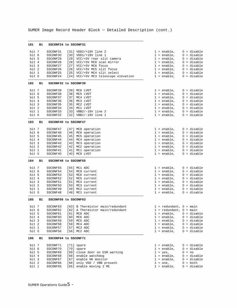
SUMER Image Record Header Block ─ Detailed Description (cont.)
──────────────────────────────────────────────────────────────181 B1 SSCONF24 to SSCONF31
bit 7 SSCONF31 [31] VDD2/+18V line 2 1 = enable, 0 = disable bit 6 SSCONF30 [30] VDD1/+18V line 1 1 = enable, 0 = disable bit 5 SSCONF29 [29] VCC/+5V rear slit camera 1 = enable, 0 = disable bit 4 SSCONF28 [28] VCC/+5V MC8 scan mirror 1 = enable, 0 = disable bit 3 SSCONF27 [27] VCC/+5V MC6 focus 1 = enable, 0 = disable bit 2 SSCONF26 [26] VCC/+5V MC5 slit focus 1 = enable, 0 = disable bit 1 SSCONF25 [25] VCC/+5V MC4 slit select 1 = enable, 0 = disable bit 0 SSCONF24 [24] VCC/+5V MC3 telescope elevation 1 = enable, 0 = disable──────────────────────────────────────────────────────────────182 B1 SSCONF32 to SSCONF39
bit 7 SSCONF39 [39] MC6 LVDT 1 = enable, 0 = disable bit 6 SSCONF38 [38] MC5 LVDT 1 = enable, 0 = disable bit 5 SSCONF37 [37] MC4 LVDT 1 = enable, 0 = disable bit 4 SSCONF36 [36] MC3 LVDT 1 = enable, 0 = disable bit 3 SSCONF35 [35] MC2 LVDT 1 = enable, 0 = disable bit 2 SSCONF34 [34] MC1 LVDT 1 = enable, 0 = disable bit 1 SSCONF33 [33] VBB2/-18V line 2 1 = enable, 0 = disable bit 0 SSCONF32 [32] VBB1/-18V line 1 1 = enable, 0 = disable──────────────────────────────────────────────────────────────183 B1 SSCONF40 to SSCONF47
bit 7 SSCONF47 [47] MC8 operation 1 = enable, 0 = disable bit 6 SSCONF46 [46] MC6 operation 1 = enable, 0 = disable bit 5 SSCONF45 [45] MC5 operation 1 = enable, 0 = disable bit 4 SSCONF44 [44] MC4 operation 1 = enable, 0 = disable bit 3 SSCONF43 [43] MC3 operation 1 = enable, 0 = disable bit 2 SSCONF42 [42] MC2 operation 1 = enable, 0 = disable bit 1 SSCONF41 [41] MC1 operation 1 = enable, 0 = disable bit 0 SSCONF40 [40] MC8 LVDT 1 = enable, 0 = disable──────────────────────────────────────────────────────────────184 B1 SSCONF48 to SSCONF55
bit 7 SSCONF55 [55] MC1 ADC 1 = enable, 0 = disable bit 6 SSCONF54 [54] MC8 current 1 = enable, 0 = disable bit 5 SSCONF53 [53] MC6 current 1 = enable, 0 = disable bit 4 SSCONF52 [52] MC5 current 1 = enable, 0 = disable bit 3 SSCONF51 [51] MC4 current 1 = enable, 0 = disable bit 2 SSCONF50 [50] MC3 current 1 = enable, 0 = disable bit 1 SSCONF49 [49] MC2 current 1 = enable, 0 = disable bit 0 SSCONF48 [48] MC1 current 1 = enable, 0 = disable──────────────────────────────────────────────────────────────185 B1 SSCONF56 to SSCONF63
bit 7 SSCONF63 [63] B Thermistor main/redundant 1 = redundant, 0 = main bit 6 SSCONF62 [62] A Thermistor main/redundant 1 = redundant, 0 = main bit 5 SSCONF61 [61] MC8 ADC 1 = enable, 0 = disable bit 4 SSCONF60 [60] MC6 ADC 1 = enable, 0 = disable bit 3 SSCONF59 [59] MC5 ADC 1 = enable, 0 = disable bit 2 SSCONF58 [58] MC4 ADC 1 = enable, 0 = disable bit 1 SSCONF57 [57] MC3 ADC 1 = enable, 0 = disable bit 0 SSCONF56 [56] MC2 ADC 1 = enable, 0 = disable──────────────────────────────────────────────────────────────186 B1 SSCONF64 to SSCONF71
bit 7 SSCONF71 [71] spare 1 = enable, 0 = disable bit 6 SSCONF70 [70] spare 1 = enable, 0 = disable bit 5 SSCONF69 [69] close door on ESR warning 1 = yes, 0 = no bit 4 SSCONF68 [68] enable watchdog 1 = enable, 0 = disable bit 3 SSCONF67 [67] enable HK monitor 1 = enable, 0 = disable bit 2 SSCONF66 [66] only VDD / VBB present 1 = one, 0 = both bit 1 SSCONF65 [65] enable moving 2 MC 1 = enable, 0 = disable
SUMER Operations Guide5 -

SUMER Image Record Header Block ─ Detailed Description (cont.)
bit 0 SSCONF64 [64] C Thermistor main/redundant 1 = redundant, 0 = main
SUMER Operations Guide5 -

SUMER Image Record Header Block ─ Detailed Description (cont.)
──────────────────────────────────────────────────────────────187 B1 SKEXPSTA Experiment Software Status
bit 1 SKOPERAT SUMER SW status: operational 1 = level 2 function is executing bit 0 SKOBSERV SUMER SW status: observational 1 = level 3 function is executing
both bits = 0: SUMER SW status: standby──────────────────────────────────────────────────────────────
SUMER Operations Guide5 -

SUMER Image Record Header Block ─ Detailed Description (cont.)
5.4.3 SUMER Housekeeping Records
5.4.3.1 SUMER HK Record 200 Idle Frame─The length of HK record 200 is 404 bytes. It is transmitted whenever no other record is available.
loc type tmname contents══════════════════════════════════════════════════════════════ 0 ┐ B2 SSYNC SUMER sync word 1 ┘ (EB 90 hex)────────────────────────────────────────────────────────────── 2 ┐ B2 SSTYP200 image record type word 3 ┘ (81 C8 hex)────────────────────────────────────────────────────────────── 4 ┐2B2 SSTIM200 record compilation time 5 ┘ (resolution: 1 s) 6 ┐ 7 ┘────────────────────────────────────────────────────────────── 8 B1 contains 01 hex ( 1)────────────────────────────────────────────────────────────── 9 B1 contains 00 hex ( 0)──────────────────────────────────────────────────────────────10 B1 contains 03 hex ( 3)──────────────────────────────────────────────────────────────11 B1 contains 02 hex ( 2)────────────────────────────────────────────────────────────── : : : : : : : : : : : :──────────────────────────────────────────────────────────────262 B1 contains FF hex (255)──────────────────────────────────────────────────────────────263 B1 contains FE hex (254)──────────────────────────────────────────────────────────────264 B1 contains 01 hex ( 1)──────────────────────────────────────────────────────────────265 B1 contains 00 hex ( 0)────────────────────────────────────────────────────────────── : : : : : : : : : : : :──────────────────────────────────────────────────────────────400 B1 contains 89 hex (137)──────────────────────────────────────────────────────────────401 B1 contains 88 hex (136)──────────────────────────────────────────────────────────────402 B1 contains 8B hex (139)──────────────────────────────────────────────────────────────403 B1 contains 8A hex (138)──────────────────────────────────────────────────────────────
SUMER Operations Guide5 -

SUMER Image Record Header Block ─ Detailed Description (cont.)
5.4.3.2 SUMER HK Record 248 Software Parameter List─
The length of HK record 248 is 72 bytes. It is sent on request only
(telecommands dump_cmd_list, dump_calib_tbl, dump_global_param,
dump_POP_param, dump_UDP, dump_UDP_param). The values are acquired just prior to
transmission.
If a software parameter list is too long to fit into a single HK record 248, as
many additional HK records 248 as required will follow the first one. loc type tmname contents══════════════════════════════════════════════════════════════ 0 ┐ B2 SSYNC SUMER sync word 1 ┘ (EB 90 hex)────────────────────────────────────────────────────────────── 2 ┐ B2 SSTYP248 image record type word 3 ┘ (81 F8 hex)────────────────────────────────────────────────────────────── 4 ┐2B2 SSTIM248 record compilation time 5 ┘ (resolution: 1 s) 6 ┐ 7 ┘────────────────────────────────────────────────────────────── 8 B1 block ID of information transmitted HKID_COMMLIST 0: command list HKID_GLOB 1: global params HKID_POP_PAR 2: POP-Params HKID_UDP 3: UDP HKID_UDP_PAR 4: UDP-params HKID_CALIB 5: calibration table────────────────────────────────────────────────────────────── 9 B1 block count range: 1 .. 255──────────────────────────────────────────────────────────────10 B1 UDP/POP/calibration-table number11 B1 spare always 0──────────────────────────────────────────────────────────────12┐┐ 4B1|2B2|B4|R4 data value/s13┘│ data format (4*B1, 2*B2, B4, or R4) depends on type of list dumped14┐│15┘┘──────────────────────────────────────────────────────────────16┐┐ 4B1|2B2|B4|R4 data value/s17┘│ data format (4*B1, 2*B2, B4, or R4) depends on type of list dumped18┐│19┘┘────────────────────────────────────────────────────────────── : : : : : :──────────────────────────────────────────────────────────────68┐┐ 4B1|2B2|B4|R4 data value/s69┘│ data format (4*B1, 2*B2, B4, or R4) depends on type of list dumped70┐│71┘┘──────────────────────────────────────────────────────────────
The records are mapped continuously onto HK248 records. The records dumped consist of:
SUMER Operations Guide5 -

SUMER Image Record Header Block ─ Detailed Description (cont.)
HKID_COMMLIST 64 command list entries of the following structure are transmitted consecutively: 1*B4 LOBT start time of command (4 most significant bytes) 1*B2 MLA word of the command loaded 1*B2 MLB1 word of the command loaded 30*B2 MLB words of the command loaded
HKID_GLOB global parameter array (refer to section 8.2, functions SystemR, SystemS, SystemU). All parameters are of type B4, I4, or R4, so high and low words are swapped.
SUMER Operations Guide5 -

SUMER Image Record Header Block ─ Detailed Description (cont.)
HKID_POP_PAR POP parameter; refer to listing of POP parameters. All parameters are of type B4, I4, or R4, so high and low words are swapped.
HKID_UDP UDP as byte dump; please note that bytes are swapped during the dump.
HKID_UDP_PAR UDP parameters are dumped. All parameters are of type B4, I4, or R4, so high and low words are swapped.
HKID_CALIB calibration parameters are dumped. All parameters are of type R4, so high and low words are swapped.
SUMER Operations Guide5 -
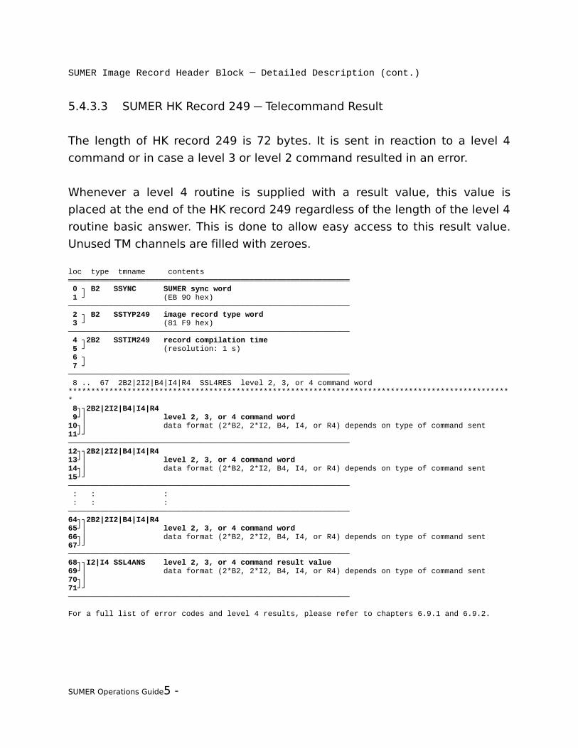
SUMER Image Record Header Block ─ Detailed Description (cont.)
5.4.3.3 SUMER HK Record 249 Telecommand Result─
The length of HK record 249 is 72 bytes. It is sent in reaction to a level 4
command or in case a level 3 or level 2 command resulted in an error.
Whenever a level 4 routine is supplied with a result value, this value is
placed at the end of the HK record 249 regardless of the length of the level 4
routine basic answer. This is done to allow easy access to this result value.
Unused TM channels are filled with zeroes.
loc type tmname contents══════════════════════════════════════════════════════════════ 0 ┐ B2 SSYNC SUMER sync word 1 ┘ (EB 90 hex)────────────────────────────────────────────────────────────── 2 ┐ B2 SSTYP249 image record type word 3 ┘ (81 F9 hex)────────────────────────────────────────────────────────────── 4 ┐2B2 SSTIM249 record compilation time 5 ┘ (resolution: 1 s) 6 ┐ 7 ┘────────────────────────────────────────────────────────────── 8 .. 67 2B2|2I2|B4|I4|R4 SSL4RES level 2, 3, or 4 command word************************************************************************************************** 8┐┐2B2|2I2|B4|I4|R4 9┘│ level 2, 3, or 4 command word10┐│ data format (2*B2, 2*I2, B4, I4, or R4) depends on type of command sent11┘┘──────────────────────────────────────────────────────────────12┐┐2B2|2I2|B4|I4|R413┘│ level 2, 3, or 4 command word14┐│ data format (2*B2, 2*I2, B4, I4, or R4) depends on type of command sent15┘┘────────────────────────────────────────────────────────────── : : : : : :──────────────────────────────────────────────────────────────64┐┐2B2|2I2|B4|I4|R465┘│ level 2, 3, or 4 command word66┐│ data format (2*B2, 2*I2, B4, I4, or R4) depends on type of command sent67┘┘──────────────────────────────────────────────────────────────68┐┐I2|I4 SSL4ANS level 2, 3, or 4 command result value69┘│ data format (2*B2, 2*I2, B4, I4, or R4) depends on type of command sent70┐│71┘┘──────────────────────────────────────────────────────────────
For a full list of error codes and level 4 results, please refer to chapters 6.9.1 and 6.9.2.
SUMER Operations Guide5 -

SUMER Image Record Header Block ─ Detailed Description (cont.)
SUMER Operations Guide5 -

SUMER Image Record Header Block ─ Detailed Description (cont.)
5.4.3.4 SUMER HK Record 250 Voltages and Currents─
The length of HK record 250 is 38 bytes. It is sent on request only
(telecommand SYS_GetHKrecord). The values are acquired just prior to
transmission.
loc type tmname contents══════════════════════════════════════════════════════════════ 0 ┐ B2 SSYNC SUMER sync word (EB 90 hex) 1 ┘────────────────────────────────────────────────────────────── 2 ┐ B2 SSTYP250 image record type word (81 FA hex) 3 ┘────────────────────────────────────────────────────────────── 4 ┐2B2 SSTIM250 record compilation time 5 ┘ (resolution: 1 s) 6 ┐ 7 ┘────────────────────────────────────────────────────────────── 8 B1 SSPOW1 Status 1 power converter channel 1
bit 7 SSP1B7 s14 converter 2 VBB 1 = on, 0 = off bit 6 SSP1B6 s13 converter 1 VBB 1 = on, 0 = off bit 5 SSP1B5 s12 wax motor (door) 1 = on, 0 = off bit 4 SSP1B4 s11 deflector 1 = on, 0 = off bit 3 SSP1B3 s10 ---obsolete--- 1 = on, 0 = off bit 2 SSP1B2 s09 converter 2 VCC 1 = on, 0 = off bit 1 SSP1B1 s08 converter 1 VCC 1 = on, 0 = off bit 0 SSP1B0 s07 VBB1 to VBB2 1 = connected, 0 = not connected────────────────────────────────────────────────────────────── 9 B1 SSPOW0 Status 0 power converter channel 0
bit 7 SSP0B7 s06 VDD1 to VDD2 1 = connected, 0 = not connected bit 6 SSP0B6 s05 converter 2 VDD 1 = on, 0 = off bit 5 SSP0B5 s04 converter 1 VDD 1 = on, 0 = off bit 4 SSP0B4 s03 converter 2 1 = on, 0 = off bit 3 SSP0B3 s02 converter 1 1 = on, 0 = off bit 2 SSP0B2 s01 converter 1 = main, 0 = redundant bit 1 SSP0B1 s00 converter emergency (main switch) 1 = on, 0 = off bit 0 SSP0B0 command transmission error 1 = error, 0 = no error──────────────────────────────────────────────────────────────10 B1 SSPOW3 Status 3 power converter channel 3
bit 7 SSP3B7 s30 VCC rear slit camera 1 = on, 0 = off bit 6 SSP3B6 s29 VCC scan mirror 1 = on, 0 = off bit 5 SSP3B5 -- obsolete -- bit 4 SSP3B4 s27 VCC grating 1 = on, 0 = off bit 3 SSP3B3 s26 VCC slit focus 1 = on, 0 = off bit 2 SSP3B2 s25 VCC slit select 1 = on, 0 = off bit 1 SSP3B1 s24 VCC telescope elevat. 1 = on, 0 = off bit 0 SSP3B0 s23 VCC telescope azimuth 1 = on, 0 = off──────────────────────────────────────────────────────────────11 B1 SSPOW2 Status 2 power converter channel 2
bit 7 SSP2B7 s22 VCC entrance door 1 = on, 0 = off bit 6 SSP2B6 s21 heater D 1 = on, 0 = off bit 5 SSP2B5 s20 heater D 1 = on, 0 = off bit 4 SSP2B4 s19 operational heater C 1 = on, 0 = off bit 3 SSP2B3 s18 operational heater B 1 = on, 0 = off
SUMER Operations Guide5 -
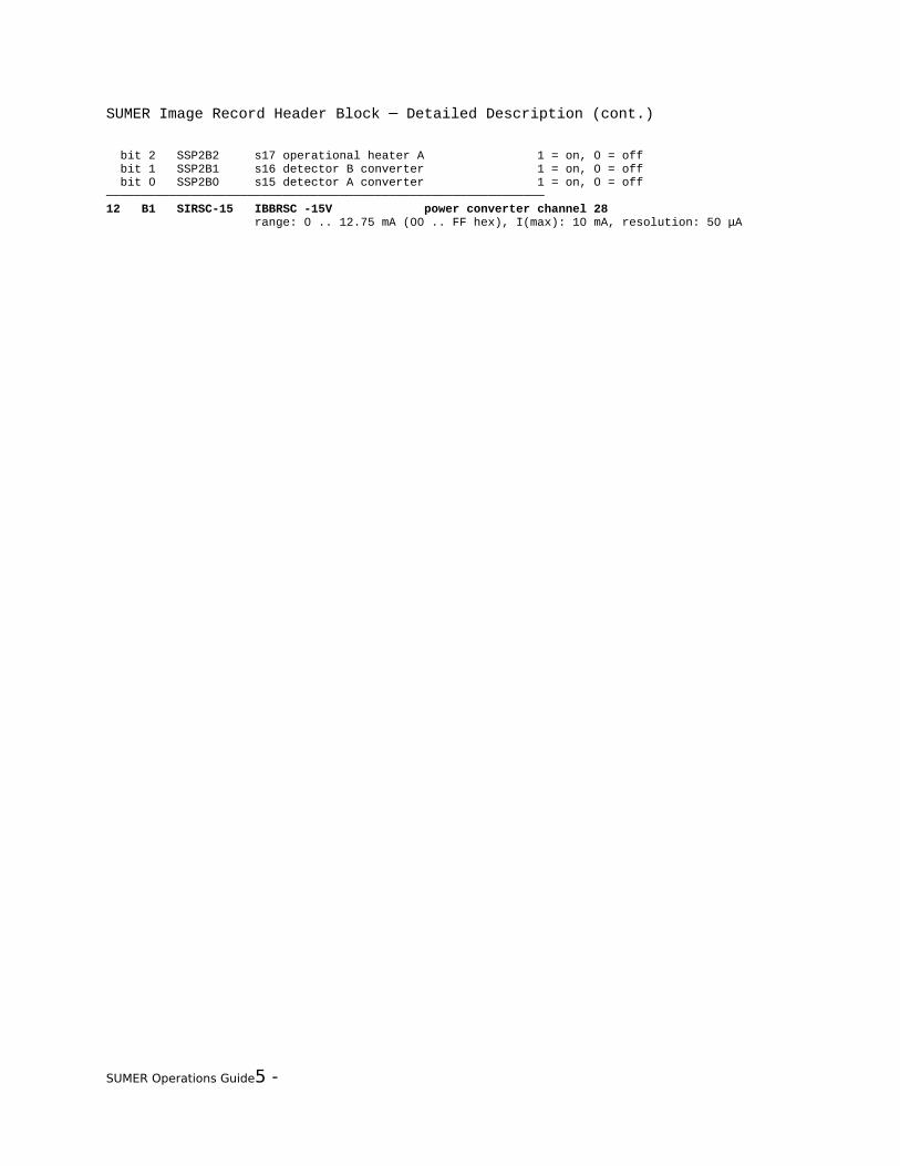
SUMER Image Record Header Block ─ Detailed Description (cont.)
bit 2 SSP2B2 s17 operational heater A 1 = on, 0 = off bit 1 SSP2B1 s16 detector B converter 1 = on, 0 = off bit 0 SSP2B0 s15 detector A converter 1 = on, 0 = off──────────────────────────────────────────────────────────────12 B1 SIRSC-15 IBBRSC -15V power converter channel 28 range: 0 .. 12.75 mA (00 .. FF hex), I(max): 10 mA, resolution: 50 μA
SUMER Operations Guide5 -

SUMER Image Record Header Block ─ Detailed Description (cont.)
──────────────────────────────────────────────────────────────13 B1 SSPOW4 STATUS 4 power converter channel 4
bit 7 SSP4B7 sp4 flight/safety plug 4 1 = connected, 0 = not connected bit 6 spare bit 6 spare bit 4 SSP4B4 sp1 test/safety plug 1 1 = connected, 0 = not connected bit 3 SSP4B3 s34 VBB2 1 = on, 0 = off bit 2 SSP4B2 s33 VBB1 1 = on, 0 = off bit 1 SSP4B1 s32 VDD2 1 = on, 0 = off bit 0 SSP4B0 s31 VDD1 1 = on, 0 = off──────────────────────────────────────────────────────────────14 B1 STSUMER4 temperature SUMER4 power converter channel 31 range: -19 .. +70.25 °C (00 .. FF hex), T(max): 40 °C, resolution: 0.35 K──────────────────────────────────────────────────────────────15 B1 S-15VRSC VBBRSC -15V power converter channel 29 range: 0 .. -18.36 V (00 .. FF hex), U(max): -15.3 V, resolution: -72 mV──────────────────────────────────────────────────────────────16 B1 SIDETB IDetB power converter channel 9 range: 0 .. 1020 mA (00 .. FF hex), I(max): 833 mA, resolution: 4 mA──────────────────────────────────────────────────────────────17 B1 SIDETA IDetA power converter channel 8 range: 0 .. 1020 mA (00 .. FF hex), I(max): 833 mA, resolution: 4 mA──────────────────────────────────────────────────────────────18 B1 ---obsolete--- power converter channel 11 ──────────────────────────────────────────────────────────────19 B1 SIHEATRD IHeaterD power converter channel 10 range: 0 .. 892.5 mA (00 .. FF hex), I(max): 740 mA, resolution: 3.5 mA──────────────────────────────────────────────────────────────20 B1 SIWAXMOT IWaxMotor Door power converter channel 13 range: 0 .. 459 mA (00 .. FF hex), I(max): 380 mA, resolution: 1.8 mA──────────────────────────────────────────────────────────────21 B1 SIDEFL IDefl power converter channel 12 range: 0 .. 51 mA (00 .. FF hex), I(max): 40 mA, resolution: 0.2 mA──────────────────────────────────────────────────────────────22 B1 S+28VBRD VBoard +28V power converter channel 15 range: 0 .. 35.7 V (00 .. FF hex), U(max): 28.3 V, resolution: 140 mV──────────────────────────────────────────────────────────────23 B1 SIBRD+28 IBoard +28V power converter channel 14 range: 0 .. 3315mA (00 .. FF hex), I(max): 2700 mA, resolution: 13 mA──────────────────────────────────────────────────────────────24 B1 S+5VCC VCC +5V power converter channel 17 range: 0 .. 7.14 V (00 .. FF hex), U(max): 5.05 V, resolution: 28 mV──────────────────────────────────────────────────────────────25 B1 SICC+5 ICC +5V power converter channel 16 range: 0 .. 1530 mA (00 .. FF hex), I(max): 1200 mA, resolution: 6 mA──────────────────────────────────────────────────────────────26 B1 S+18VDD1 VDD1 +18V power converter channel 19 range: 0 .. 22.95 V (00 .. FF hex), U(max): 18.9 V, resolution: 90 mV──────────────────────────────────────────────────────────────27 B1 SIDD1+18 IDD1 +18V power converter channel 18 range: 0 .. 1275 mA (00 .. FF hex), I(max): 1050 mA, resolution: 5 mA──────────────────────────────────────────────────────────────28 B1 S+18VDD2 VDD2 +18V power converter channel 21 range: 0 .. 22.95 V (00 .. FF hex), U(max): 18.9 V, resolution: 90 mV──────────────────────────────────────────────────────────────29 B1 SIDD2+18 IDD2 +18V power converter channel 20 range: 0 .. 1275 mA (00 .. FF hex), I(max): 1050 mA, resolution: 5 mA──────────────────────────────────────────────────────────────30 B1 S-18VBB1 VBB1 -18V power converter channel 23 range: 0 .. -22.95 V (00 .. FF hex), U(max): -18.9 V, resolution: -90 mV──────────────────────────────────────────────────────────────31 B1 SIBB1-18 IBB1 -18V power converter channel 22 range: 0 .. 1275 mA (00 .. FF hex), I(max): 1050 mA, resolution: 5 mA
SUMER Operations Guide5 -
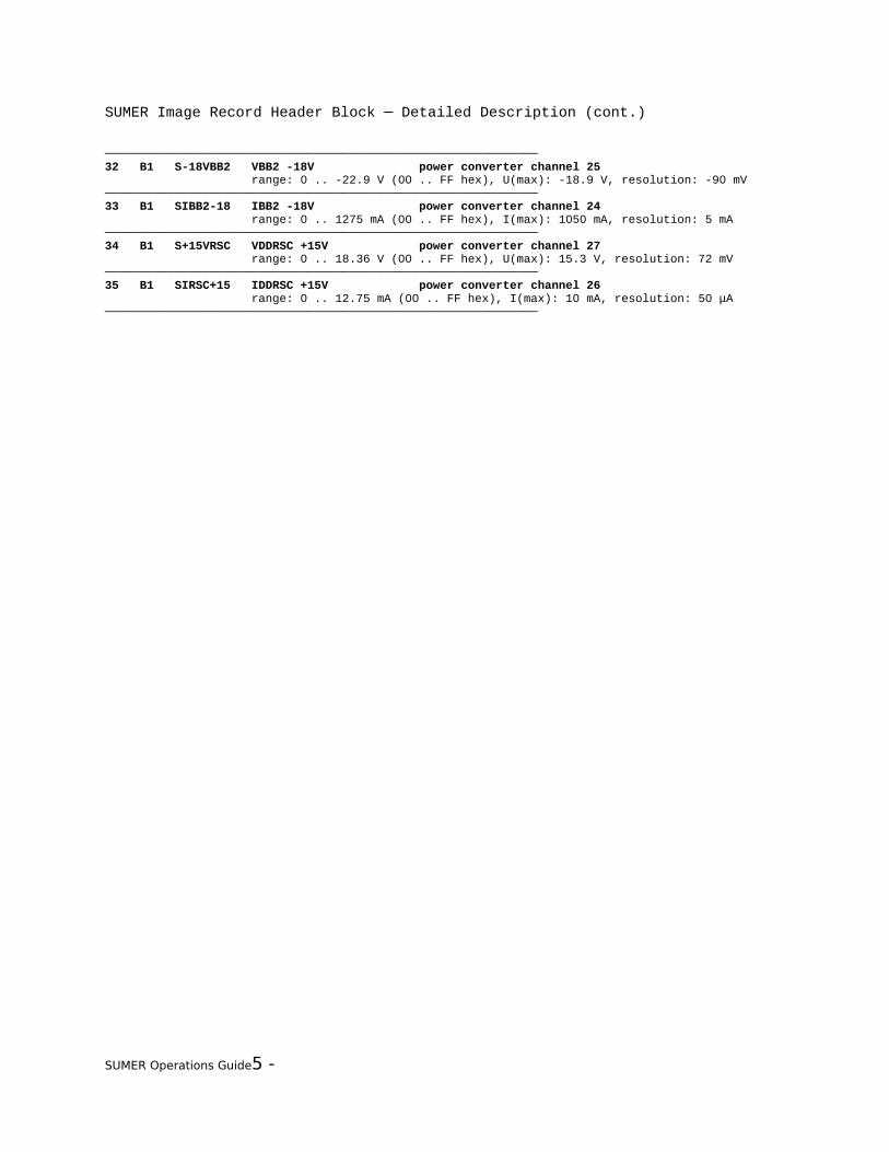
SUMER Image Record Header Block ─ Detailed Description (cont.)
──────────────────────────────────────────────────────────────32 B1 S-18VBB2 VBB2 -18V power converter channel 25 range: 0 .. -22.9 V (00 .. FF hex), U(max): -18.9 V, resolution: -90 mV──────────────────────────────────────────────────────────────33 B1 SIBB2-18 IBB2 -18V power converter channel 24 range: 0 .. 1275 mA (00 .. FF hex), I(max): 1050 mA, resolution: 5 mA──────────────────────────────────────────────────────────────34 B1 S+15VRSC VDDRSC +15V power converter channel 27 range: 0 .. 18.36 V (00 .. FF hex), U(max): 15.3 V, resolution: 72 mV──────────────────────────────────────────────────────────────35 B1 SIRSC+15 IDDRSC +15V power converter channel 26 range: 0 .. 12.75 mA (00 .. FF hex), I(max): 10 mA, resolution: 50 μA──────────────────────────────────────────────────────────────
SUMER Operations Guide5 -

SUMER Image Record Header Block ─ Detailed Description (cont.)
5.4.3.5 SUMER HK Record 251 Motor Controller Data─
The length of HK record 251 is 26 bytes. It is sent on request only
(telecommand SYS_GetHKrecord). The values are acquired just prior to
transmission.
loc type tmname contents══════════════════════════════════════════════════════════════ 0 ┐ B2 SSYNC SUMER sync word (EB 90 hex) 1 ┘────────────────────────────────────────────────────────────── 2 ┐ B2 SSTYP251 image record type word (81 FB hex) 3 ┘────────────────────────────────────────────────────────────── 4 ┐2B2 SSTIM251 record compilation time 5 ┘ (resolution: 1 s) 6 ┐ 7 ┘────────────────────────────────────────────────────────────── 8 B1 SIMC-18M MCx -18V supply current / during motion measured during motion, i.e. current of motor, LVDT, and ADC range: 0 .. 1020 mA (00 .. FF hex), resolution: 4 mA────────────────────────────────────────────────────────────── 9 B1 SIMC+18M MCx +18V supply current / during motion measured during motion, i.e. current of motor, LVDT, and ADC range: 0 .. 1020 mA (00 .. FF hex), resolution: 4 mA──────────────────────────────────────────────────────────────10 B1 SIMC-18R MCx -18V supply current / on request measured on request, i.e. current of LVDT and ADC range: 0 .. 1020 mA (00 .. FF hex), resolution: 4 mA──────────────────────────────────────────────────────────────11 B1 SIMC+18R MCx +18V supply current / on request measured on request, i.e. current of LVDT and ADC range: 0 .. 1020 mA (00 .. FF hex), resolution: 4 mA──────────────────────────────────────────────────────────────12 B1 S-15MC MCx -15V range: 0 .. -20.40 V (00 .. FF hex), resolution: 80 mV──────────────────────────────────────────────────────────────13 B1 S+15MC MCx +15V range: 0 .. 20.40 V (00 .. FF hex), resolution: 80 mV──────────────────────────────────────────────────────────────14 B1 STMCT1 MCx temperature 1 (motor driver stage) range: 0 .. 127 °C (00 .. FF hex), resolution: 0.5 K──────────────────────────────────────────────────────────────15 B1 S+5MC MCx +5V range: 0 .. 10.20 V (00 .. FF hex), resolution: 40 mV──────────────────────────────────────────────────────────────16 B1 STMCT3 MCx temperature 3 (external temperature) temperature 3 (STMCT3) is computed from - rawt3: the ADC 16-bit output value (stored in locations 24-25) - fk : the calibration factor (stored in calibration table 1) - ak : the calibration offset (stored in calibration table 1) by calculating: STMCT3 = rawt3 * fk + ak
MC2: range: -0.960 .. +80.940 °C, resolution: 0.320 K MC1, MC3 .. MC6, MC8: range: +15.000 .. +25.200 °C, resolution: 0.040 K──────────────────────────────────────────────────────────────17 B1 STMCT2 MCx temperature 2 (motor) range: 0 .. 127 °C (00 .. FF hex), resolution: 0.5 K
SUMER Operations Guide5 -
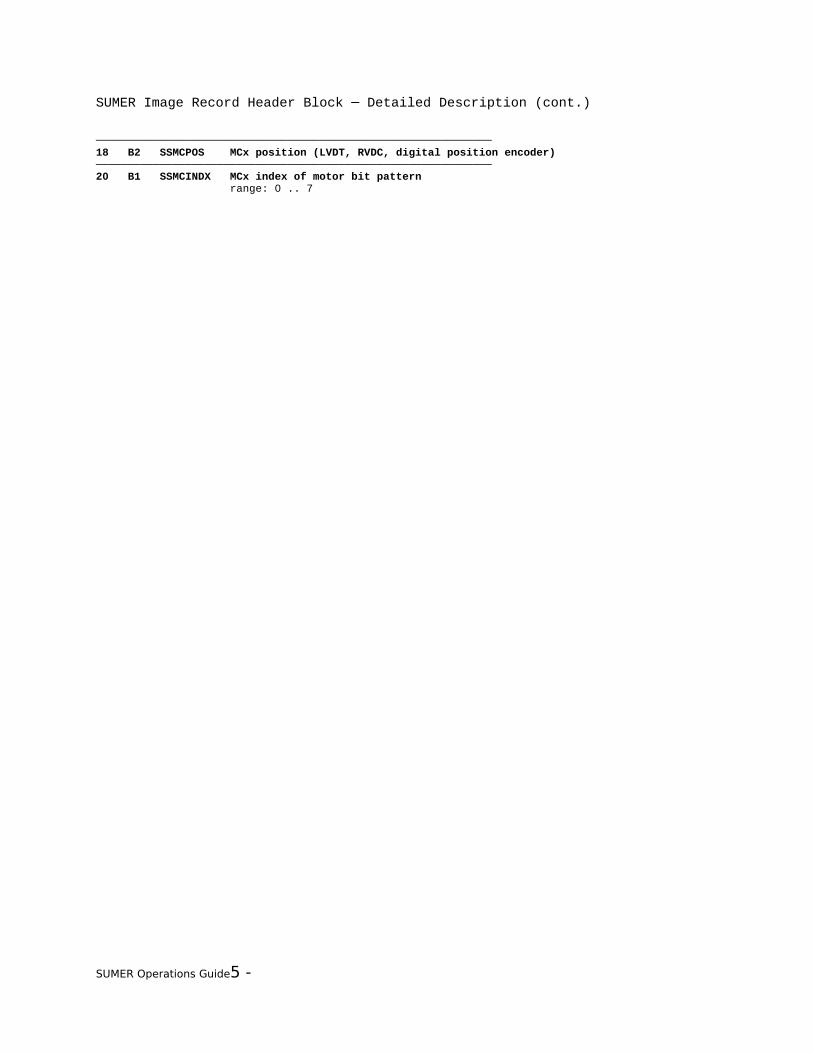
SUMER Image Record Header Block ─ Detailed Description (cont.)
──────────────────────────────────────────────────────────────18 B2 SSMCPOS MCx position (LVDT, RVDC, digital position encoder)──────────────────────────────────────────────────────────────20 B1 SSMCINDX MCx index of motor bit pattern range: 0 .. 7
SUMER Operations Guide5 -

SUMER Image Record Header Block ─ Detailed Description (cont.)
──────────────────────────────────────────────────────────────21 B1 SSMC MCx status
bit 7 SSMCxERR 1 = error bit 6 SSMCxCMD 1 = command executed bit 5 SSMCxEPO 1 = encoder power off bit 4 SSMCxETO 1 = encoder timeout bit 3 SSMCxRES 1 = reset bit 2 SSMCxADC 1 = ADC power off
MC0 .. MC6:bits 1-0 spare MC8:bits 1-0 SSMC8IAS IAS encoder bits 17 and 16──────────────────────────────────────────────────────────────22 B1 SSMCN motor control processor number 0 = MC1-Door 1 = MC2-Azimuth 2 = MC3-Elevation 3 = MC4-Slit select 4 = MC5-Slit focus 5 = MC6-Grating 6 = MC8-Scan──────────────────────────────────────────────────────────────23 B1 SE21 spare ──────────────────────────────────────────────────────────────24 ┐ B2 (SE22) raw value of ADC output of temperature 3 (external temperature)25 ┘ range: -0.960 .. +80.940 °C (0000 hex .. FFFF hex), resolution: 0.020 K──────────────────────────────────────────────────────────────
SUMER Operations Guide5 -

SUMER Image Record Header Block ─ Detailed Description (cont.)
5.4.3.6 SUMER HK Record 252 Detector Data─
The length of HK record 252 is 56 bytes. It is sent on request only
(telecommand SYS_GetHKrecord). The values are acquired just prior to
transmission.
loc type tmname contents══════════════════════════════════════════════════════════════ 0 ┐ B2 SSYNC SUMER sync word (EB 90 hex) 1 ┘────────────────────────────────────────────────────────────── 2 ┐ B2 SSTYP252 image record type word (81 FC hex) 3 ┘────────────────────────────────────────────────────────────── 4 ┐2B2 SSTIM252 record compilation time 5 ┘ (resolution: 1 s) 6 ┐ 7 ┘──────────────────────────────────────────────────────────────8...55 48*B1 SYXDL XDL data channels8 12*B1 SYXPHAX XDL X PHA data (2nd byte in 12, 3rd in 16 etc.)10 12*B1 SYXPHAY XDL Y PHA data (2nd byte in 14, 3rd in 18 etc.******************************************************************************************************* 8 B1 SYXPHAX XDL X PHA Data_______________________________________________________________________________________________________ 9 B1 SIXLVPI LVPS Current Monitor 0.113 W * SIXLVPI_______________________________________________________________________________________________________10 B1 SYXPHAY XDL Y PHA Data_______________________________________________________________________________________________________11 B1 SSXACCEL Post Accel HV Status N = 0.044 * SSXPOST - 0.156 0<N<1 for normal operation, when on_______________________________________________________________________________________________________12 B1 SYXPHAX XDL X PHA Data_______________________________________________________________________________________________________13 B1 S+XMCPV MCP Voltage Monitor -22.18 V * S+XMCPV_______________________________________________________________________________________________________14 B1 SYXPHAY XDL Y PHA Data_______________________________________________________________________________________________________15 B1 SIXMCPI MCP Current Monitor 0.98 * SIXMCPI - 0.668 * S+XMCPV + 81.02 (uA)_______________________________________________________________________________________________________16 B1 SYXPHAX XDL X PHA Data_______________________________________________________________________________________________________17 B1 S+XTDC5 +5V Monitor for TDC Box supply 0.0366V * S+XTDC5_________________________________________________________________________________________________
SUMER Operations Guide5 -

SUMER Image Record Header Block ─ Detailed Description (cont.)
______18 B1 SYXPHAY XDL Y PHA Data_______________________________________________________________________________________________________19 B1 S-XTDC5 -5V Monitor for TDC Box supply 0.0816V * S-XTDC5 - 15.826_______________________________________________________________________________________________________20 B1 SYXPHAX XDL X PHA Data_______________________________________________________________________________________________________21 B1 S+XTDC10 +10V Monitor for TDC Box supply 0.088V * S+XTDC10_______________________________________________________________________________________________________22 B1 SYXPHAY XDL Y PHA Data_______________________________________________________________________________________________________23 B1 S-XTDC15 -15V Monitor for TDC Box supply 0.202V * S-XTDC15 - 46.49_______________________________________________________________________________________________________24 B1 SYXPHAX XDL X PHA Data_______________________________________________________________________________________________________25 B1 S+XMON13 +13V Monitor for Monitor Box supply 0.0853V * S+XMON13_______________________________________________________________________________________________________26 B1 SYXPHAY XDL Y PHA Data_______________________________________________________________________________________________________27 B1 S-XMON13 -13V Monitor for Monitor Box supply 0.178V * S-XMON13 - 40.28_______________________________________________________________________________________________________28 B1 SYXPHAX XDL X PHA Data_______________________________________________________________________________________________________29 B1 S+XMON5 +5V Monitor for Monitor Box supply 0.0392V * S+XMON5 _______________________________________________________________________________________________________30 B1 SYXPHAY XDL Y PHA Data_______________________________________________________________________________________________________31 B1 S+XTIMX X Timing Threshold 0.0196V * S+XTIMX _______________________________________________________________________________________________________32 B1 SYXPHAX XDL X PHA Data_______________________________________________________________________________________________________33 B1 S+XCHX X Charge Threshold 0.0196V * S+XCHX _______________________________________________________________________________________________________34 B1 SYXPHAY XDL Y PHA Data_______________________________________________________________________________________________________35 B1 S+XTIMY Y Timing Threshold 0.0196V * S+XTIMY _______________________________________________________________________________________________________36 B1 SYXPHAX XDL X PHA Data
SUMER Operations Guide5 -
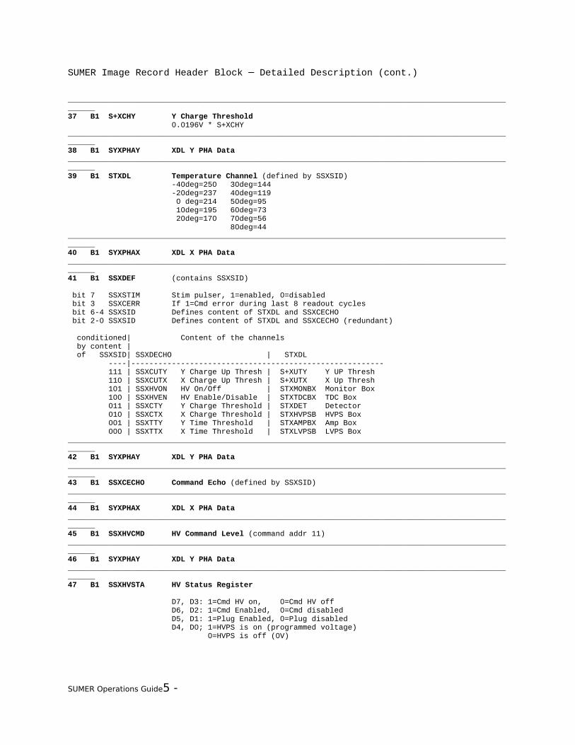
SUMER Image Record Header Block ─ Detailed Description (cont.)
_______________________________________________________________________________________________________37 B1 S+XCHY Y Charge Threshold 0.0196V * S+XCHY_______________________________________________________________________________________________________38 B1 SYXPHAY XDL Y PHA Data_______________________________________________________________________________________________________39 B1 STXDL Temperature Channel (defined by SSXSID) -40deg=250 30deg=144 -20deg=237 40deg=119 0 deg=214 50deg=95 10deg=195 60deg=73 20deg=170 70deg=56 80deg=44 _______________________________________________________________________________________________________40 B1 SYXPHAX XDL X PHA Data_______________________________________________________________________________________________________41 B1 SSXDEF (contains SSXSID)
bit 7 SSXSTIM Stim pulser, 1=enabled, 0=disabled bit 3 SSXCERR If 1=Cmd error during last 8 readout cycles bit 6-4 SSXSID Defines content of STXDL and SSXCECHO bit 2-0 SSXSID Defines content of STXDL and SSXCECHO (redundant) conditioned| Content of the channels by content | of SSXSID| SSXDECHO | STXDL ----|-------------------------------------------------------- 111 | SSXCUTY Y Charge Up Thresh | S+XUTY Y UP Thresh 110 | SSXCUTX X Charge Up Thresh | S+XUTX X Up Thresh 101 | SSXHVON HV On/Off | STXMONBX Monitor Box 100 | SSXHVEN HV Enable/Disable | STXTDCBX TDC Box 011 | SSXCTY Y Charge Threshold | STXDET Detector 010 | SSXCTX X Charge Threshold | STXHVPSB HVPS Box 001 | SSXTTY Y Time Threshold | STXAMPBX Amp Box 000 | SSXTTX X Time Threshold | STXLVPSB LVPS Box_______________________________________________________________________________________________________42 B1 SYXPHAY XDL Y PHA Data_______________________________________________________________________________________________________43 B1 SSXCECHO Command Echo (defined by SSXSID)_______________________________________________________________________________________________________44 B1 SYXPHAX XDL X PHA Data_______________________________________________________________________________________________________45 B1 SSXHVCMD HV Command Level (command addr 11)_______________________________________________________________________________________________________46 B1 SYXPHAY XDL Y PHA Data_______________________________________________________________________________________________________47 B1 SSXHVSTA HV Status Register
D7, D3: 1=Cmd HV on, 0=Cmd HV off D6, D2: 1=Cmd Enabled, 0=Cmd disabled D5, D1: 1=Plug Enabled, 0=Plug disabled D4, D0; 1=HVPS is on (programmed voltage) 0=HVPS is off (0V)
SUMER Operations Guide5 -
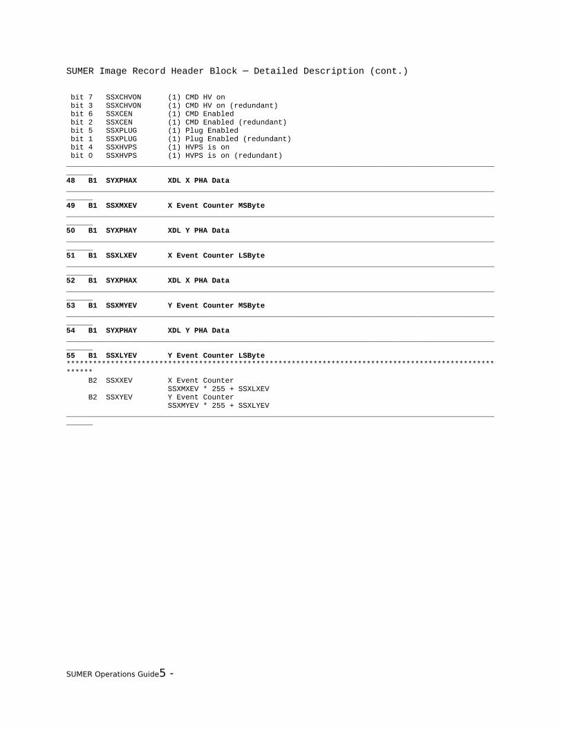
SUMER Image Record Header Block ─ Detailed Description (cont.)
bit 7 SSXCHVON (1) CMD HV on bit 3 SSXCHVON (1) CMD HV on (redundant) bit 6 SSXCEN (1) CMD Enabled bit 2 SSXCEN (1) CMD Enabled (redundant) bit 5 SSXPLUG (1) Plug Enabled bit 1 SSXPLUG (1) Plug Enabled (redundant) bit 4 SSXHVPS (1) HVPS is on bit 0 SSXHVPS (1) HVPS is on (redundant)_______________________________________________________________________________________________________48 B1 SYXPHAX XDL X PHA Data_______________________________________________________________________________________________________49 B1 SSXMXEV X Event Counter MSByte_______________________________________________________________________________________________________50 B1 SYXPHAY XDL Y PHA Data_______________________________________________________________________________________________________51 B1 SSXLXEV X Event Counter LSByte_______________________________________________________________________________________________________52 B1 SYXPHAX XDL X PHA Data_______________________________________________________________________________________________________53 B1 SSXMYEV Y Event Counter MSByte_______________________________________________________________________________________________________54 B1 SYXPHAY XDL Y PHA Data_______________________________________________________________________________________________________55 B1 SSXLYEV Y Event Counter LSByte******************************************************************************************************* B2 SSXXEV X Event Counter SSXMXEV * 255 + SSXLXEV B2 SSXYEV Y Event Counter SSXMYEV * 255 + SSXLYEV_______________________________________________________________________________________________________
SUMER Operations Guide5 -

SUMER Image Record Header Block ─ Detailed Description (cont.)
5.4.3.7 SUMER HK Record 255 Cycle Time 1 s─
The length of HK record 255 is 26 bytes. It is sent every second. The values
are acquired just prior to transmission.
loc type tmname contents══════════════════════════════════════════════════════════════ 0 ┐ B2 SSYNC SUMER sync word (EB 90 hex) 1 ┘────────────────────────────────────────────────────────────── 2 ┐ B2 SSTYP255 image record type word (81 FF hex) 3 ┘────────────────────────────────────────────────────────────── 4 ┐2B2 SSTIM255 record compilation time 5 ┘ (resolution: 1 s) 6 ┐ 7 ┘────────────────────────────────────────────────────────────── 8 B1 SKEXPSTA Experiment Software Status
bit 1 SKOPERAT SUMER SW status: operational 1 = level 2 function is executing bit 0 SKOBSERV SUMER SW status: observational 1 = level 3 function is executing both bits 0: SUMER SW status: standby────────────────────────────────────────────────────────────── 9 B1 SKCMDNR number of commands in command list range: 0 .. 63──────────────────────────────────────────────────────────────10 ┐ B2 SKUNCOMP number of uncompressed files in RAM disk11 ┘──────────────────────────────────────────────────────────────12 ┐ B2 SKCOMP number of compressed files in RAM disk13 ┘──────────────────────────────────────────────────────────────14 B1 SSECPERR ECP error status register bits 7-4: powerfail at physical memory banks bits 3-0: double bit errors in data words
bit 7 0 = no powerfail at physical memory bank 3 1 = powerfail at physical memory bank 3
bit 6 0 = no powerfail at physical memory bank 2 1 = powerfail at physical memory bank 2
bit 5 0 = no powerfail at physical memory bank 1 1 = powerfail at physical memory bank 1
bit 4 0 = no powerfail at physical memory bank 0 1 = powerfail at physical memory bank 0
bit 3 0 = no error in data word D16-D31 1 = double bit error in data word D16-D31
bit 2 0 = no error in data word D00-D15 1 = double bit error in data word D00-D15
bit 1 0 = no error in data word D16-D31 1 = double bit error in data word D16-D31
bit 0 0 = no error in data word D00-D15 1 = double bit error in data word D00-D15
SUMER Operations Guide5 -

SUMER Image Record Header Block ─ Detailed Description (cont.)
──────────────────────────────────────────────────────────────15 B1 SSSPUERR SPU Error Status Register bits 7-4: powerfail at physical memory banks bits 3-0: double bit errors in data words description: see location 14 above
SUMER Operations Guide5 -

SUMER Image Record Header Block ─ Detailed Description (cont.)
──────────────────────────────────────────────────────────────16 ┐ B2 SSIIM IIM status register17 ┘
bit 15 SSIIMCRM 1 = clear DPU channel 0 = random access to DPU channel bit 14 SSIIMSCR 1 = selected channel ready 0 = selected channel not ready bit 13 SSIIMPSB 1 = power status ch B on 0 = power status ch B off bit 12 SSIIMPSA 1 = power status ch A on 0 = power status ch A off bit 11 SSIIMDEB 1 = double bit error ch B 0 = no double bit errors ch B bit 10 SSIIMSEB 1 = single bit error ch B 0 = no single bit errors ch B bit 9 SSIIMDEA 1 = double bit error ch A 0 = no double bit errors ch A bit 8 SSIIMSEA 1 = single bit error ch A 0 = no single bit errors ch A bit 7 SSIIMLSB 1 = latch up strobe ch B (low threshold) 0 = high LU trigger threshold ch B bit 6 SSIIMLSA 1 = latch up strobe ch A (low threshold) 0 = high LU trigger threshold ch A bit 5 SSIIMPCB 1 = power command ch B on 0 = power command ch B off bit 4 SSIIMPCA 1 = power command ch A on 0 = power command ch A off bit 3 SSIIMSTP 1 = set power 0 = hold power status bit 2 SSIIMCHS 1 = channel B to DPU 0 = channel A to DPU bit 1 SSIIMING 1 = input gate open 0 = input gate closed bit 0 SSIIMACR 1 = auto clear on 0 = auto clear off──────────────────────────────────────────────────────────────18 ┐ B2 SKL3ID L3 function identifier (MLB1)19 ┘ for a full list of L3 function identifiers, please refer to section 6.1──────────────────────────────────────────────────────────────20 ┐ I2 SKL3RES L3 result21 ┘ for a full list of L3 result values, please refer to section 6.9.1──────────────────────────────────────────────────────────────22 B1 SKCMDLST command list disabled/enabled 1 = enabled, 0 = disabled──────────────────────────────────────────────────────────────23 B1 SKMCID MC number of MC position24 ┐ I2 MC position in units of motor half steps25 ┘ -1: not initialized if SKMCID = 0: MC1-Door default range: 0 .. 18000 if SKMCID = 1: MC2-Azimuth default range: 0 .. 10000 if SKMCID = 2: MC3-Elevation default range: 0 .. 10000 if SKMCID = 3: MC4-Slit select default range: -2100 .. 2000 if SKMCID = 4: MC5-Slit focus default range: 0 .. 3200 if SKMCID = 5: MC6-Grating default range: 200 .. 20440 if SKMCID = 6: MC8-Scan default range: 250 .. 12400──────────────────────────────────────────────────────────────
SUMER Operations Guide5 -
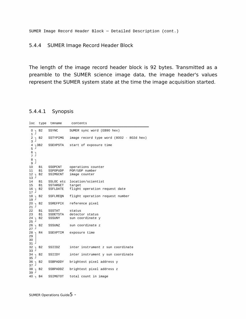
SUMER Image Record Header Block ─ Detailed Description (cont.)
5.4.4 SUMER Image Record Header Block
The length of the image record header block is 92 bytes. Transmitted as a
preamble to the SUMER science image data, the image header's values
represent the SUMER system state at the time the image acquisition started.
5.4.4.1 Synopsis
loc type tmname contents ══════════════════════════════════════════════════════════════ 0 ┐ B2 SSYNC SUMER sync word (EB90 hex) 1 ┘ 2 ┐ B2 SSTYPIMG image record type word (8002 - 802d hex) 3 ┘ 4 ┐3B2 SSEXPSTA start of exposure time 5 ┘ 6 ┐ 7 ┘ 8 ┐ 9 ┘10 B1 SSOPCNT operations counter11 B1 SSPOPUDP POP/UDP number12 ┐ B2 SSIMGCNT image counter13 ┘14 B1 SSLOC etc location/scientist15 B1 SSTARGET target16 ┐ B2 SSFLDATE flight operation request date17 ┘18 ┐ B2 SSFLREQN flight operation request number19 ┘20 ┐ B2 SSREFPIX reference pixel21 ┘22 B1 SSSTAT status23 B1 SSDETSTA detector status24 ┐ B2 SSSUNY sun coordinate y25 ┘26 ┐ B2 SSSUNZ sun coordinate z27 ┘28 ┐ R4 SSEXPTIM exposure time29 │30 │31 ┘32 ┐ B2 SSIIDZ inter instrument z sun coordinate33 ┘34 ┐ B2 SSIIDY inter instrument y sun coordinate35 ┘36 ┐ B2 SSBPADDY brightest pixel address y37 ┘38 ┐ B2 SSBPADDZ brightest pixel address z39 ┘40 ┐ B4 SSIMGTOT total count in image
SUMER Operations Guide5 -

SUMER Image Record Header Block ─ Detailed Description (cont.)
41 │42 │43 ┘44 ┐ R4 SSROTCOMP rotation compensation time45 │46 │47 ┘48 ┐ B2 SSBPCNTS brightest pixel counts49 ┘50 ┐ B2 SSACIMGC accumulative image counter51 ┘
SUMER Operations Guide5 -

SUMER Image Record Header Block ─ Detailed Description (cont.)
52 ┐ I2 SSSTEPN number of raster steps53 ┘54 I1 SSSTEPSZ raster step size in elementary motor steps55 B1 SSSLITN number of slit selected56 ┐ B2 SSBINNY binning y_D57 ┘58 ┐ B2 SSBINNZ binning z_D59 ┘60 ┐ B2 SSXCNT x event count61 ┘62 ┐ B2 SSYCNT y event count63 ┘64 B1 S-MCPV MCP high voltage65 B1 SIMCPI MCP current66 ┐ I2 SSMC2POS MC2-Azimuth position67 ┘68 ┐ I2 SSMC3POS MC3-Elevation position69 ┘70 ┐ I2 SSMC4POS MC4-Slit select position71 ┘72 ┐ I2 SSMC8POS MC8-Scan Mirror position73 ┘74 B1 SSMCERR motor controller error75 B1 SSCOMPRM method of data compression76 ┐ R4 SSWAVEL wavelength at reference pixel77 │78 │79 ┘80 ┐ B2 SSCOMPP1 compression parameter 181 ┘82 ┐ B2 SSCOMPP2 compression parameter 283 ┘84 ┐ B2 SSCOMPP3 compression parameter 385 ┘86 ┐ B2 administration counter87 ┘88 ┐ I2 SSMC6POS MC6-Grating position89 ┘90 B1 spare91 B1 spare
───────────────────────────────────────────────────────
───────
SUMER Operations Guide5 -

SUMER Image Record Header Block ─ Detailed Description (cont.)
5.4.4.2 Detailed Description
loc type tmname contents══════════════════════════════════════════════════════════════ 0 ┐ B2 SSYNC SUMER sync word 1 ┘ (EB 90 hex)────────────────────────────────────────────────────────────── 2 ┐ B2 SSTYPIMG image record type word 3 ┘ (80 02 .. 80 2D hex)────────────────────────────────────────────────────────────── 4 ┐3B2 SSEXPSTA start of exposure time 5 ┘ The OBT and LOBT use the CCSDS format (1958 January 1 epoch). It is an 6 ┐ unsegmented time code with a basic time equal to 1 second. The time field will be 7 ┘ constituted of 6 bytes: 4 bytes for course time (20 to 231 seconds), 2 bytes for 8 ┐ fine time. The resolution of the fine time is 2-11 seconds: 9 ┘ |231...224|223...216|215...28|27...20|2-1...2-8|2-9...2-11 0 0 0 0 0|──────────────────────────────────────────────────────────────10 B1 SSOPCNT operations counter 0 after switch on, increased by one with every new operation (POP or UDP)──────────────────────────────────────────────────────────────11 B1 SSPOPUDP POP/UDP number no POP/UDP executing: 0, range: POPs 1 .. 36, UDPs 1 .. 16──────────────────────────────────────────────────────────────12 ┐ B2 SSIMGCNT image counter13 ┘ reset at start of operation and by spectrohelio, incremented for every image──────────────────────────────────────────────────────────────14 B1 SSLOC etc location/scientist as set by telecommand SYS_Operatorbits 7-6 SSLOC location (id number of the place of order)bits 5-0 SSSCIENT scientist (id number of the originator of the observation)──────────────────────────────────────────────────────────────15 B1 SSTARGET target as set by telecommand SYS_Operator identification for the location of a specific event, range: 0 .. 63──────────────────────────────────────────────────────────────16 ┐ B2 SSFLDATE flight operation request date17 ┘ as set by telecommand SYS_Operator date is indicated in units of days, start day is 1, counts up to 11 years range: 0 .. 2047 as set by telecommand SYS_Operator──────────────────────────────────────────────────────────────18 ┐ B2 SSFLREQN flight operation request number19 ┘ as set by telecommand SYS_Operator range: 0 .. 2047──────────────────────────────────────────────────────────────20 ┐ B2 SSREFPIX reference pixel21 ┘ reference pixel where to set lambda1, range: 0 .. 1023──────────────────────────────────────────────────────────────22 B1 SSSTAT status
bit 7 SSEETRIG explosive event trigger bit 6 SSFF flat field correction: 1 = on, 0 = offbits 5-4 SSDETTYP detector: 01 = B, 10 = A, 11 = RSC (for S-MCPV and SIMCPI)bits 3-2 SSINTSTA IIF/TC spectrohelio interrupt status: 00 = no interrupts allowed 01 = IIF interrupts allowed 10 = TC interrupts allowed 11 = IIF and TC interrupts allowedbits 1-0 always 0──────────────────────────────────────────────────────────────23 B1 SSDETSTA detector status
SUMER Operations Guide5 -
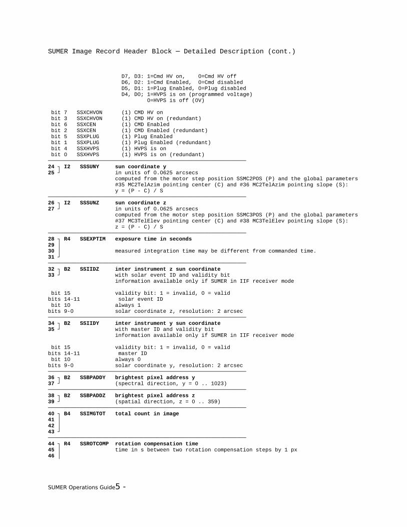
SUMER Image Record Header Block ─ Detailed Description (cont.)
D7, D3: 1=Cmd HV on, 0=Cmd HV off D6, D2: 1=Cmd Enabled, 0=Cmd disabled D5, D1: 1=Plug Enabled, 0=Plug disabled D4, D0; 1=HVPS is on (programmed voltage) 0=HVPS is off (0V) bit 7 SSXCHVON (1) CMD HV on bit 3 SSXCHVON (1) CMD HV on (redundant) bit 6 SSXCEN (1) CMD Enabled bit 2 SSXCEN (1) CMD Enabled (redundant) bit 5 SSXPLUG (1) Plug Enabled bit 1 SSXPLUG (1) Plug Enabled (redundant) bit 4 SSXHVPS (1) HVPS is on bit 0 SSXHVPS (1) HVPS is on (redundant)──────────────────────────────────────────────────────────────24 ┐ I2 SSSUNY sun coordinate y25 ┘ in units of 0.0625 arcsecs computed from the motor step position SSMC2POS (P) and the global parameters #35 MC2TelAzim pointing center (C) and #36 MC2TelAzim pointing slope (S): y = (P - C) / S──────────────────────────────────────────────────────────────26 ┐ I2 SSSUNZ sun coordinate z27 ┘ in units of 0.0625 arcsecs computed from the motor step position SSMC3POS (P) and the global parameters #37 MC3TelElev pointing center (C) and #38 MC3TelElev pointing slope (S): z = (P - C) / S──────────────────────────────────────────────────────────────28 ┐ R4 SSEXPTIM exposure time in seconds29 │ 30 │ measured integration time may be different from commanded time.31 ┘ ──────────────────────────────────────────────────────────────32 ┐ B2 SSIIDZ inter instrument z sun coordinate33 ┘ with solar event ID and validity bit information available only if SUMER in IIF receiver mode
bit 15 validity bit: 1 = invalid, 0 = validbits 14-11 solar event ID bit 10 always 1bits 9-0 solar coordinate z, resolution: 2 arcsec──────────────────────────────────────────────────────────────34 ┐ B2 SSIIDY inter instrument y sun coordinate35 ┘ with master ID and validity bit information available only if SUMER in IIF receiver mode
bit 15 validity bit: 1 = invalid, 0 = validbits 14-11 master ID bit 10 always 0bits 9-0 solar coordinate y, resolution: 2 arcsec──────────────────────────────────────────────────────────────36 ┐ B2 SSBPADDY brightest pixel address y37 ┘ (spectral direction, y = 0 .. 1023)──────────────────────────────────────────────────────────────38 ┐ B2 SSBPADDZ brightest pixel address z39 ┘ (spatial direction, z = 0 .. 359)──────────────────────────────────────────────────────────────40 ┐ B4 SSIMGTOT total count in image41 │42 │43 ┘──────────────────────────────────────────────────────────────44 ┐ R4 SSROTCOMP rotation compensation time45 │ time in s between two rotation compensation steps by 1 px46 │
SUMER Operations Guide5 -

SUMER Image Record Header Block ─ Detailed Description (cont.)
47 ┘──────────────────────────────────────────────────────────────48 ┐ B2 SSBPCNTS brightest pixel counts49 ┘──────────────────────────────────────────────────────────────50 ┐ B2 SSACIMGC accumulative image counter51 ┘ (starts at 0 after booting, is never reset, will wrap over from 65535 to 0)──────────────────────────────────────────────────────────────52 ┐ I2 SSSTEPN number of raster steps53 ┘ if positive: telecope scans E->W, if negative: telescope scans W->E
SUMER Operations Guide5 -

SUMER Image Record Header Block ─ Detailed Description (cont.)
──────────────────────────────────────────────────────────────54 I1 SSSTEPSZ raster step size in elementary motor steps if negative: "Schmierschritt" (cf. ch. 8.2, spectrohelio)──────────────────────────────────────────────────────────────55 B1 SSSLITN number of slit selected 0: no slit selected, 1 .. 9: slit # selected──────────────────────────────────────────────────────────────56 ┐ B2 SSBINNY binning y_D57 ┘ binning factor in spectral direction, min: 1, max: 1024, possible values depend on image and transmission formats──────────────────────────────────────────────────────────────58 ┐ B2 SSBINNZ binning z_D59 ┘ binning factor in spatial direction, min: 1, max: 360, possible values depend on image and transmission formats──────────────────────────────────────────────────────────────60 ┐ B2 SSXCNT x event count61 ┘──────────────────────────────────────────────────────────────62 ┐ B2 SSYCNT y event count63 ┘──────────────────────────────────────────────────────────────64 B1 S-MCPV MCP high voltage -22.18 V * S-MCPV ──────────────────────────────────────────────────────────────65 B1 SIMCPI MCP current 0.98 * SIMCPI - 0.668 * S-MCPV + 81.02 (μA) ──────────────────────────────────────────────────────────────66 ┐ I2 SSMC2POS MC2-Azimuth position67 ┘ in units of motor half steps (0.38 arcsec) -1: not initialized, default range: 0 .. 10000,──────────────────────────────────────────────────────────────68 ┐ I2 SSMC3POS MC3-Elevation position69 ┘ in units of motor half steps (0.38 arcsec) -1: not initialized, default range: 0 .. 10000──────────────────────────────────────────────────────────────70 ┐ I2 SSMC4POS MC4-Slit select position71 ┘ in units of motor half steps -1: not initialized, default range: -2100 .. +2000──────────────────────────────────────────────────────────────72 ┐ I2 SSMC8POS MC8-Scan Mirror position73 ┘ in units of motor half steps -1: not initialized, default range: 250 .. 12400──────────────────────────────────────────────────────────────74 B1 SSMCERR motor controller error motor controller error bits from MC1 .. MC8 status information
bit 7 spare bit 6 SSMC8ERR MC8-Scan bit 5 SSMC6ERR MC6-Grating bit 4 SSMC5ERR MC5-Slit Focus bit 3 SSMC4ERR MC4-Slit Select bit 2 SSMC3ERR MC3-Elevation bit 1 SSMC2ERR MC2-Azimuth bit 0 SSMC1ERR MC1-Door──────────────────────────────────────────────────────────────75 B1 SSCOMPRM method of data compression range: -17 .. +17──────────────────────────────────────────────────────────────76 ┐ R4 SSWAVEL wavelength at reference pixel77 │ range: 400 Å .. 1600 Å78 │79 ┘
SUMER Operations Guide5 -

SUMER Image Record Header Block ─ Detailed Description (cont.)
──────────────────────────────────────────────────────────────80 ┐ B2 SSCOMPP1 compression parameter 181 ┘ for the compression scheme (cmp) found in location 75 (SSCOMPRM) cmp = 0: 0 cmp = ±1: 13 cmp = ±2: 16 cmp = ±3: 23 cmp = ±4: 26 cmp = ±5: 33 cmp = ±6: 53 cmp = ±7: 61 cmp = ±8: 62 cmp = ±9: 64 cmp = ±10: 71 cmp = ±11: 72 cmp = ±12: 74 cmp = ±13: 81 cmp = ±14: 82 cmp = ±15: 84 cmp = ±16: 0 cmp = ±17: maximum line 1──────────────────────────────────────────────────────────────82 ┐ B2 SSCOMPP2 compression parameter 283 ┘ for the compression scheme (cmp) found in location 75 (SSCOMPRM) cmp = 0: 0 cmp = ±1: brightest pixel count (SSBPCNTS) cmp = ±2: 0 cmp = ±3: brightest pixel count (SSBPCNTS) cmp = ±4: 0 cmp = ±5: brightest pixel count (SSBPCNTS) cmp = ±6: brightest pixel count corrected for background values cmp = ±7: averaged width cmp = ±8: averaged width cmp = ±9: 0 cmp = ±10: averaged width cmp = ±11: averaged width cmp = ±12: 0 cmp = ±13: 0 cmp = ±14: 0 cmp = ±15: 0 cmp = ±16: 0 cmp = ±17: maximum line 2──────────────────────────────────────────────────────────────84 ┐ B2 SSCOMPP3 compression parameter 385 ┘ for the compression scheme (cmp) found in location 75 (SSCOMPRM) cmp = 0: 0 cmp = ±1: minimum pixel count in image cmp = ±2: 0 cmp = ±3: minimum pixel count in image cmp = ±4: 0 cmp = ±5: minimum pixel count in image cmp = ±6: 0 cmp = ±7: averaged centroid cmp = ±8: 0 cmp = ±9: 0 cmp = ±10: averaged centroid cmp = ±11: 0 cmp = ±12: 0 cmp = ±13: 0 cmp = ±14: 0 cmp = ±15: 0 cmp = ±16: 0 cmp = ±17: maximum line 3
SUMER Operations Guide5 -
SUMER Image Record Header Block ─ Detailed Description (cont.)
──────────────────────────────────────────────────────────────86 ┐ B2 administration counter87 ┘ as set by telecommand SYS_Operator──────────────────────────────────────────────────────────────88 ┐ I2 SSMC6POS MC6-Grating position89 ┘ in units of motor half steps -1: not initialized, default range: 200 .. 20440──────────────────────────────────────────────────────────────90 B1 spare91 B1 spare
SUMER Operations Guide5 -

SUMER Image Record Header Block ─ Detailed Description (cont.)
SUMER Operations Guide5 -