SECTION 5: SPECIFICATIONS - Salem Municipal … · IS: 2502 – 1963 Code of practice for bending...
93
Contractor 1 SALEM CITY MUNICIPAL CORPORATION THIRD TAMILNADU URBAN DEVELOPMENT PROJECT DEDICATED WATER SUPPLY SCHEME TO SALEM CITY MUNICIPAL CORPORATION NATIONAL COMPETITIVE BIDDING PACKAGE VIII WORKS (CIVIL WORKS) NAME OF WORK: Supplying, Laying, Jointing, Testing & commissioning of Water Supply Distribution Networks with Ductile Iron (DI) Pipes and providing House Service Connections with MDPE pipes for Dedicated Water Supply Scheme to Salem City Municipal Corporation. VOLUME II/IV SECTION 5: SPECIFICATIONS
Transcript of SECTION 5: SPECIFICATIONS - Salem Municipal … · IS: 2502 – 1963 Code of practice for bending...

Contractor 1
SALEM CITY MUNICIPAL CORPORATION
THIRD TAMILNADU URBAN DEVELOPMENT PROJECT
DEDICATED WATER SUPPLY SCHEME TO SALEM CITY MUNICIPAL
CORPORATION
NATIONAL COMPETITIVE BIDDING
PACKAGE VIII WORKS
(CIVIL WORKS)
NAME OF WORK: Supplying, Laying, Jointing, Testing & commissioning of Water Supply Distribution
Networks with Ductile Iron (DI) Pipes and providing House Service Connections with MDPE pipes for Dedicated
Water Supply Scheme to Salem City Municipal Corporation.
VOLUME II/IV
SECTION 5: SPECIFICATIONS

Contractor 2
SECTION 5:
SPECIFICATIONS
Contractor 3
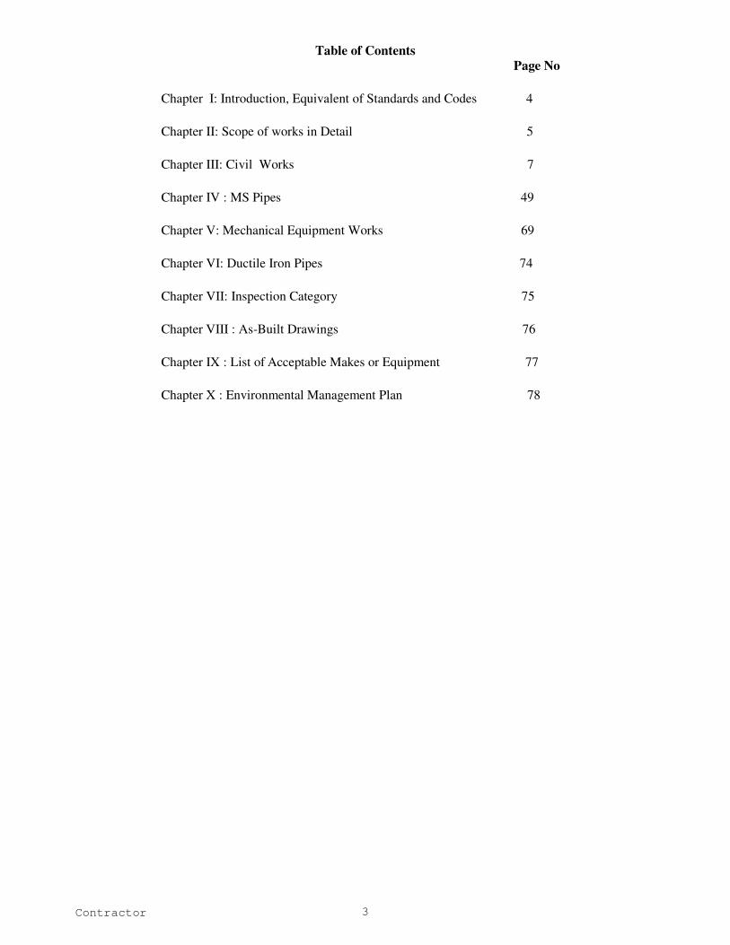
Table of Contents
Page No
Chapter I: Introduction, Equivalent of Standards and Codes 4
Chapter II: Scope of works in Detail 5
Chapter III: Civil Works 7
Chapter IV : MS Pipes 49
Chapter V: Mechanical Equipment Works 69
Chapter VI: Ductile Iron Pipes 74
Chapter VII: Inspection Category 75
Chapter VIII : As-Built Drawings 76
Chapter IX : List of Acceptable Makes or Equipment 77
Chapter X : Environmental Management Plan 78

Contractor 4
CHAPTER I
Introduction, equivalent of standards and codes
INTRODUCTION
This contract work is for Supplying, Laying, Jointing, Testing & commissioning of Water Supply Distribution Networks
with Ductile Iron (DI) Pipes and providing House Service Connections with MDPE pipes for Dedicated Water Supply
Scheme to Salem City Municipal Corporation.
EQUIVALENT OF STANDARDS AND CODES
Wherever reference is made in the contract to specific standards and codes to be met by the materials, plant, and other
supplies to be furnished, and work performed or tested, the provisions of the latest current edition or revision of the
relevant I.S standards and codes in effect shall apply, unless otherwise expressly stated in the contract. Where such
standards and codes are International, national or relate to a particular country or region, other authoritative standards
which ensure a substantially equal or higher performance than the standards and codes specified will be accepted subject
to the Engineer's prior review and written approval. Differences between the standards specified and the proposed
alternative standards must be fully described in writing by the Contractor and submitted to the Engineer at least 28 days
prior to the date when the Contractor desires the Engineer’s approval. In the event the Engineer determines that such
proposed deviations do not ensure substantially equal performance, the Contractor shall comply with the standards
specified in the documents.
Wherever reference is made in the Contract to specific manufacture’s or trade name, the Contractor shall be entitled to
substitute plant and materials supplied by other manufacture’s products. Such substitutions shall be subject to the
approval of the Engineer. At the request of the Engineer, the Contractor shall provide full evidence to establish that the
substituted plant / material is equal to or better than that from the manufacturers or suppliers mentioned in the Contract.
.
Contractor 5
CHAPTER II
SCOPE OF WORK
Dedicated water supply scheme to Salem city Municipal Corporation has been prepared with the provision for
implementation in two stages. Under stage I the works involving raw water intake and pumping arrangement,
construction of new water treatment plant, clear water pumping station, clear water booster stations, ridge sump and
conveying main for raw water and clear water up to Salem city corporation limit entry point has been tendered out under
five packages and the works are under progress.
The works under stage II in this Package VIII consist of Supplying, Laying, Jointing, Testing & commissioning of Water
Supply Distribution Networks with Ductile Iron (DI) Pipes and providing House Service Connections with MDPE pipes
for Dedicated Water Supply Scheme to Salem City Municipal Corporation.
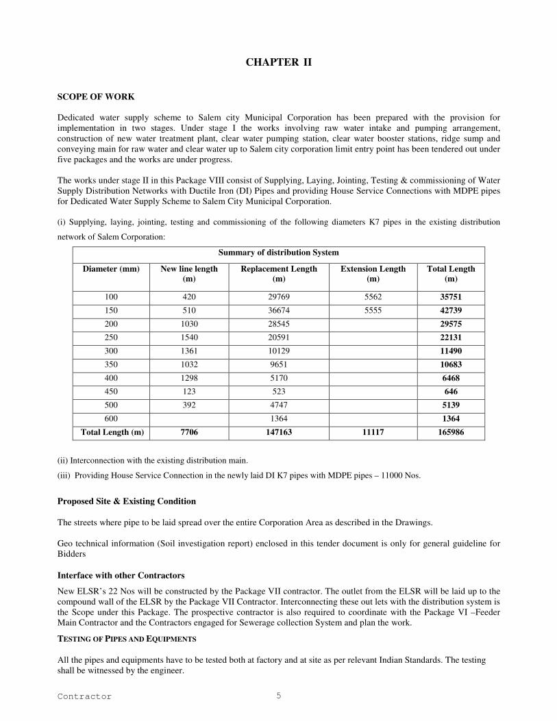
(i) Supplying, laying, jointing, testing and commissioning of the following diameters K7 pipes in the existing distribution
network of Salem Corporation:
Summary of distribution System
Diameter (mm) New line length
(m)
Replacement Length
(m)
Extension Length
(m)
Total Length
(m)
100 420 29769 5562 35751
150 510 36674 5555 42739
200 1030 28545 29575
250 1540 20591 22131
300 1361 10129 11490
350 1032 9651 10683
400 1298 5170 6468
450 123 523 646
500 392 4747 5139
600 1364 1364
Total Length (m) 7706 147163 11117 165986
(ii) Interconnection with the existing distribution main.
(iii) Providing House Service Connection in the newly laid DI K7 pipes with MDPE pipes – 11000 Nos.
Proposed Site & Existing Condition
The streets where pipe to be laid spread over the entire Corporation Area as described in the Drawings.
Geo technical information (Soil investigation report) enclosed in this tender document is only for general guideline for
Bidders
Interface with other Contractors
New ELSR’s 22 Nos will be constructed by the Package VII contractor. The outlet from the ELSR will be laid up to the
compound wall of the ELSR by the Package VII Contractor. Interconnecting these out lets with the distribution system is
the Scope under this Package. The prospective contractor is also required to coordinate with the Package VI –Feeder
Main Contractor and the Contractors engaged for Sewerage collection System and plan the work.
TESTING OF PIPES AND EQUIPMENTS
All the pipes and equipments have to be tested both at factory and at site as per relevant Indian Standards. The testing
shall be witnessed by the engineer.
Contractor 6
CHAPTER III
CIVIL WORKS
1.0 GENERAL
1.1 MATERIALS:
The term “Materials” shall mean all materials, goods and articles of every kind whether raw, processed or
manufactured and equipment and plant of every kind to be supplied by the Contractor for incorporation in the
works.
All materials shall be new and of the kinds and qualities described in the contract and shall be at least equal to
approved samples.
Materials shall be transported, handled and stored in such a manner as to prevent deterioration, damage or
contamination failing which such damaged materials will be rejected and shall not be used on any part of the
works under this contract.
1.2 SAMPLES AND TESTS OF MATERIALS:
The Contractor shall submit samples of such materials as may be required by the Engineer and shall carry out
the specified tests directed by the Engineer at the Site, at the supplier’s premises or at a laboratory approved by
the Engineer.
Samples shall be submitted and tests shall be carried out sufficiently early to enable further samples to be
submitted and tested if required by the Engineer.
The Contractor shall give the Engineer minimum fifteen days notice in writing of the date on which any of the
materials will be ready for testing or inspection at the supplier’s premises or at a laboratory approved by the
Engineer. The Engineer or his nominee shall attend the test at the appointed place within fifteen days of the
said date on which the materials are expected to be ready for testing or inspection according to the Contractor,
failing which the test may proceed in his absence unless instructed by the Engineer to carry out such a test on a
mutually agreed upon date in his presence. The Contractor shall in any case submit to the Engineer within
seven days of every test such number of certified copies (not exceeding six) of the test readings as the Engineer
may require.
Approval by the Engineer for placing orders for materials or for samples or tests shall not prejudice any of the
Engineer’s powers under the Contract particularly under the provisions of Conditions of Contract.
The provisions of this clause shall also apply to materials supplied under any nominated sub-contract.
STANDARDS:
The special attention of the Contractor is drawn to the relevant sections and clauses of the National Building
Code of India (latest revision) and latest I.S. Specifications (latest editions as amended) and should follow all
the specifications and conditions strictly.
Materials and workmanship shall comply with the relevant Indian Standards or any other National standards
equivalent or higher than Indian standard (with amendments) current on the date of submission of tender only.
Where the relevant standard provides for the furnishing of a certificate to the Employer, at his request, stating
that the materials supplied comply in all respects with the standards, the Contractor shall obtain the certificate
and forward it to the Engineer.
Contractor 7
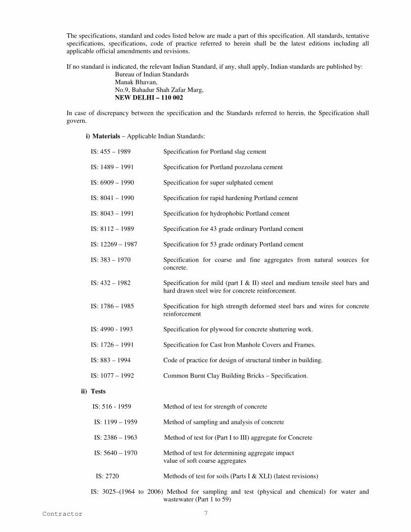
The specifications, standard and codes listed below are made a part of this specification. All standards, tentative
specifications, specifications, code of practice referred to herein shall be the latest editions including all
applicable official amendments and revisions.
If no standard is indicated, the relevant Indian Standard, if any, shall apply, Indian standards are published by:
Bureau of Indian Standards
Manak Bhavan,
No.9, Bahadur Shah Zafar Marg,
NEW DELHI – 110 002
In case of discrepancy between the specification and the Standards referred to herein, the Specification shall
govern.
i) Materials – Applicable Indian Standards:
IS: 455 – 1989 Specification for Portland slag cement
IS: 1489 – 1991 Specification for Portland pozzolana cement
IS: 6909 – 1990 Specification for super sulphated cement
IS: 8041 – 1990 Specification for rapid hardening Portland cement
IS: 8043 – 1991 Specification for hydrophobic Portland cement
IS: 8112 – 1989 Specification for 43 grade ordinary Portland cement
IS: 12269 – 1987 Specification for 53 grade ordinary Portland cement
IS: 383 – 1970 Specification for coarse and fine aggregates from natural sources for
concrete.
IS: 432 – 1982 Specification for mild (part I & II) steel and medium tensile steel bars and
hard drawn steel wire for concrete reinforcement.
IS: 1786 – 1985 Specification for high strength deformed steel bars and wires for concrete
reinforcement
IS: 4990 - 1993 Specification for plywood for concrete shuttering work.
IS: 1726 – 1991 Specification for Cast Iron Manhole Covers and Frames.
IS: 883 – 1994 Code of practice for design of structural timber in building.
IS: 1077 – 1992 Common Burnt Clay Building Bricks – Specification.
ii) Tests
IS: 516 - 1959 Method of test for strength of concrete
IS: 1199 – 1959 Method of sampling and analysis of concrete
IS: 2386 – 1963 Method of test for (Part I to III) aggregate for Concrete
IS: 5640 – 1970 Method of test for determining aggregate impact
value of soft coarse aggregates
IS: 2720 Methods of test for soils (Parts I & XLI) (latest revisions)
IS: 3025–(1964 to 2006) Method for sampling and test (physical and chemical) for water and
wastewater (Part 1 to 59)
Contractor 8
iii) Code of practice
IS: 456 – 2000 Plain and Reinforced concrete – Code of Practice
IS: 800 – 1984 Code of practice for general construction in steel
IS: 2502 – 1963 Code of practice for bending and fixing of bars for concrete reinforcement
IS: 3558 – 1983 Code of practice for use of immersion vibrators for consolidating concrete
IS: 10005 – 1994 SI Units and Recommendations for the use of their Multiples and of certain
other units.
IS: 10262 – 1982 Recommended guidelines for concrete mix design
IS: 4111 Part 1 – 1986 Manholes (first revision)
IS: 4111 Part 4 – 1986 Pumping stations and Pumping mains (rising main)
iv) Construction Safety
IS: 3696 Safety code of scaffolds (Parts I & II) and ladders (latest revisions)
IS: 2750 – 1964 Specification for steel scaffolding
IS: 3764 – 1992 Code of safety for excavation work
v) Steel
IS: 2751 – 1979 Code of practice for welding of M.S. Plain & Deformed Bars for reinforced
concrete construction
IS: 9417 – 1989 Recommendations for welding cold worked steel bars for reinforced
concrete construction
IS: 10790 - 1984 Methods of sampling of steel for prestressed and reinforced concrete part 2
Reinforcing steel.
IS: 1566 – 1982 Specification for Hard-drawn steel wire fabric concrete reinforcement.
IS: 280 - 1978 Specification for Mild Steel Wire for General Engineering.
vi) Brickwork plastering
IS: 2116 – 1980 Specification for Sand for masonry mortars.
IS: 3495 – 1992 Methods of test of Burnt clay Building Bricks (Part 1 – 4)
vii) Sanitary Appliances
IS: 1726 – 1974 Specification for cast iron manhole covers and frames - Part 1 to 8
IS: 5455 – 1969 Specification for cast iron steps for Manholes
IS: 5312 – 1984 Specification for swing check type reflux (non return valves – Part 1 & 2
viii) Sluice Valves
IS: 1364 Hexagon Head Bolts, Screws and Nuts of product Grade A and B (Part 1 –
6 latest revision)
IS: 638 – 1979 Specification for sheet rubber jointing and rubber insertion jointing.

Contractor 9
IS: 2685 – 1971 Code of practice for selection, installation and maintenance of sluice valves.
IS: 14846 – 2000 Sluice valve for water works purposes (50 to 1200mm size) – Specification
ix) Ductile Iron Pipes
IS: 8329 – 2000 Centrifugally cast (spun) Ductile Iron pressure pipes for water, gas and
sewage - Specification
IS: 5382 - 1985 Specification for Rubber sealing rings for gas mains, water mains and
sewers.
IS: 3400 Methods of test for vulcanized rubbers (Part 1 – 23 - latest revisions)
IS: 13655 – 1993 Guidelines for Heat Treatment of Cast Iron.
IS: 1500 – 2005 Methods for brinell hardness test for metallic materials.
IS: 9523 – 2000 Ductile Iron fittings for pressure pipes for Water, Gas & Sewage –
Specification.
IS: 12288 – 1987 Code of practice for use and laying of Ductile Iron Pipes.
IS: 2062 – 1999 Steel for General Structural purposes – Specification.
x) SW Pipes
IS: 651 - 1980 Salt glazed stoneware pipes and fittings (fourth revision)
IS: 4127 - 1983 Code of practice for laying glazed Stoneware Pipes (First revision).
xi) Manuals
Tamil Nadu Building Practice
Manual on Sewerage and Sewage Treatment published by CPHEEO
A. Specifications for Civil Works
In the event of any discrepancy between the provisions of the Standard Specifications and the
Particular Specifications, then the provisions of the Particular Specifications will prevail.
B. Particular Specifications
SPECIAL CONDITIONS
1.4 CONSTRUCTION WATER:
The Contractor shall make his own arrangement for the fresh water required for construction of civil works and
testing of pipeline and hydraulic structures as well as for the potable water required for his labour camps.
1.5 CONSTRUCTION POWER:
The Contractor shall make his own arrangement for supply of electrical energy required at his sites and the
works.

Contractor 10
1.6 TEMPORARY FENCING:
The Contractor shall, at his own expense, erect and maintain in good condition temporary fences and gates
along the boundaries of the areas assigned, if any, to him by the employer for the purpose of the execution of
the works.
The Contractor shall, except when authorized by the Engineer, confine his men, materials and plant within the
site of which he is given possession. The Contractor shall not use any part of the site for purposes not
connected with the works unless prior written consent of the Engineer has been obtained. Access shall be made
to such areas only by way of approved gateways.
1.7 SANITARY FACILITIES:
The Contractor shall provide and maintain in clean and sanitary condition adequate W.C.’s and wash places,
which may be required on the various parts of the site or use of his employees, to the satisfaction of the
Engineer. The Contractor shall make all arrangements for the disposal of sewage of drainage in accordance
with the directions of the Engineer.
1.8 RESTRICTED ENTRY TO SITE:
The Contractor shall get the prior permission of the Engineer before any person not directly connected with the
works to visit the site.
1.9 EXISTING SERVICES:
Drains, pipes, cables, overhead electric wires and similar services encountered in the course of the works shall
be guarded from injury by the Contractor at his own cost, so that they may continue in full and uninterrupted
use to the satisfaction of the Employer and the Contractor shall not store materials or otherwise occupy any part
of the ‘site’ in a manner likely to hinder the operation of such services. The Contractor must make good or bear
the cost of making good, the damage done by him on any mains, pipes, cables or lines (whether above or below
ground), whether shown or not shown in the drawings, without delay to the satisfaction of the Engineer and the
Employer.
1.10 ELECTRIC POWER SUPPLY:
1. The Electrical Power required has to be obtained by the Contractor from the Tamil Nadu Electricity
Board.
2. The Contractor is forewarned that there can be interruptions in power supply for reasons beyond the
control of the Tamil Nadu Electricity Board and therefore the contractor is advised to make his standby
arrangement to provide and maintain all essential power supply for his work area at his expense. The
contractor shall not be entitled to any compensation for any loss or damage to his machinery or any
equipment or any consequential loss in progress of work and idle labour as a result of any interruptions
in Power supply.
1.11 NOTICE TO TELEPHONE, RAILWAYS & ELECTRICITY SUPPLY UNDER TAKING:
Before commencing operations the contractor has to obtain permission from local bodies / Highways
Department when he wants to cut any section of the road. the employer will give necessary assistance such as
sending letters and attending meetings if required. The employer will also pay necessary charges towards
restoration of roads to the Salem Corporation / State Highways and National Highways. Any delay in getting
the permission from the Corporation / Panchayats / Municipalities, State Highways Department, National
Highways Department, Railway Department, Electricity Board, Telegraphs Department, Traffic Department
attached to the police and other departments or companies for carrying out the work will be to the account of
contractor.
The contractor before taking up operations, which involve cutting of roads, shifting utilities etc., during the
progress of the work, shall give notice to the concerned authorities viz. the Corporation / Panchayats /
Municipalities, State Highways Department, National Highways Department, Railway Department, Electricity
Board, Telegraphs Department, Traffic Department attached to the police and other departments or companies
as may be affected by the work. The notice should identify the specific details so that the necessary diversion of
traffic may be arranged and permissions obtained. The contractor shall co-operate with the department
Contractor 11
concerned and provide for necessary barricading of roads, protection to existing underground cables etc., met
with during the excavation of trenches. The contractor shall provide at his own expenses watching and lighting
arrangements during day and night and erect required notice board such as “Caution Road closed for Traffic”
etc.,. He should also provide and maintain at his own cost the necessary supports for underground cables etc., to
afford best protection to them in consultation with the authorities in charge of the properties and to their best
satisfaction. The contractor has to make necessary arrangements to get supply of electricity from TNEB for
operating the machinery and equipments. The employer will pay the necessary service connection and S.D
charges. The contractor should obtain all approvals for installation and commissioning of machinery and
accessories offered by them from the respective inspecting authorities such as CEIG or CEFG etc., Fees if any,
to be paid to the inspecting authorities will be reimbursed by the Employer.
1.12 PERMISSION FOR ROAD CUTS:
Wherever the Contractor considers that it is necessary to cut through an existing road or track he shall submit
details to the Engineer for approval, a minimum of seven days before such work commences.
In the event of cutting a road by the Contractor without the written permission from the Engineer, the
Contractor shall be responsible for the cost of reinstating the road as undertaken by the Municipal Road
Department or the Highways Department, as the case may be, notwithstanding the general procedures included
in specification for earth work. Where all permissions are correctly obtained the cost of such reinstatement will
be paid directly by the employer.
1.13 TEMPORARY DIVERSION OF ROADS:
During the execution of the work the Contractor shall make at his cost all necessary provision for the temporary
diversion of roads, cart-tracks, footpaths, drains, water courses, channels etc., if he fail to do so, the same shall
be done by the Engineer and the cost thereof will be recovered from the Contractor.
1.14 BARRICADING:
To prevent persons from injury and to avoid damage to the property, adequate barricades, construction sign,
torches, red lanterns and guards as required shall be provided and maintained during the progress of the
construction work and until it is safe for traffic to use the roadways. The manhole trench shall be barricaded on
all four sides. Barricading for laying pipe lines consists of fixing casuarina posts 8 - 10cm dia. and 1.52m high
at 1.53m centre to centre tied with coir ropes. Barrication also includes watching during night, fixing danger
flags, danger lights / reflector and painting in different colours. The Contractor who has dug up the trench shall
be responsible for any mishap, which may occur.
1.15 FILLING IN HOLES AND TRENCHES ETC.:
The Contractor immediately upon completion of the Works shall fill up holes and trenches which may have
been made or dug, level the mounds, or heaps or earth that may have been raised or made, and clear away all
rubbish which may have become superfluous or have been occasioned or made in the execution of the works,
and the Contractor shall bear and pay all costs, charges etc.
1.16 ACCIDENTS:
It shall be the duty of the Contractor to arrange for the execution of the works in such a manner as to avoid the
possibility of the accidents to persons or damage to the properties at any state of the progress of work.
Nevertheless he shall be held wholly responsible for any injury or damage to persons and properties, which may
occur irrespective of any precautions he may take during the execution of the works. The Contractor shall make
good all claims and loss arising out of such accidents and indemnify the Employer from all such claims and
expenses on account thereof.
1.17 WATER AND LIGHTING:
The Contractor shall pay all fees and provide water and light as required from Municipal mains or other sources
and shall pay all charges, thereof (including storage tanks, meters etc.) for the use of the works and workmen,
unless otherwise arranged and decided on by writing with Engineer. The water used for the works shall be free
from earthy vegetable or organic matter and from salts or other substances likely to interfere with the setting of
mortar or otherwise prove harmful to the work and conform to relevant standards.
Contractor 12
1.18 PAYMENT TO LABOURERS:
The Contractor should note, that in the event of emergency, he shall pay all labourers every day and if this is not
done, the Corporation shall make requisite payment and recover the cost from the Contractor. The Contractor
shall not employ any labourer below age of 15 years.
1.19 EQUIVALENCE OF STANDARDS AND CODES:
Whenever reference is made in the contract to the respective standards and codes in accordance with which
plant, equipment or materials are to be furnished and work is to be performed or tested the provisions of the
latest current edition or revision of the relevant standards and codes in effect shall apply, unless otherwise
expressly set forth in the contract. Where such standards and codes are national in character, or relate to a
particular country or region, other authoritative standards which ensure equal or higher quality than the
standards and codes specified will be accepted subject to the prior review and written approval by the Engineer.
Difference between the standards specified and the proposed authoritative standards must be fully described in
writing by the Contractor and submitted to the Engineer well in advance for approval. If on the prior review,
the Engineer determines that such proposed deviations do not ensure equal or higher quality; the Contractor
shall comply with the standards set forth in the contract documents.
The Contractor should use only accepted makes of materials and plant and should construct the entire Works
according to Specifications, Standards, data sheets, drawings etc. If no makes are specified then only
manufacturers of Plant and materials corresponding to the state of the Art technology and / or confirming to the
latest Indian / International standards shall be used. Providing materials of approved quality and confirming to
the standards does not relieve the Contractor from being responsible for the successful performance of all
system components.
1.20 SAFETY PROVISION:
1.20.1 General Requirements for Health and Safety:
The safety provision shall be brought to the notice of all concerned by displaying on a notice board at a
prominent place at the work spot, persons responsible for ensuring compliance with the safety provision shall be
named therein by the Contractor.
To ensure effective enforcement of the rules and regulations relating to safety precautions, arrangements made
by the Contractor shall be open to inspection by the Engineer or his representative and the inspecting officer.
Notwithstanding the above provision Contractor is not exempted from the operation of any other Act or rules in
force relating to safety provisions.
1.20.2 Protection of the Public:
No material on any of the sites shall be so stocked or placed as to cause danger or inconvenience to any person
or to the public. The Contractor shall provide all necessary fencing and lights to protect public from accidents
and shall be bound to bear expenses of defense of every suit, action or proceedings of law that may be brought
by any person for injury sustaining, owing to neglect the above precautions and to any such suit, action or
proceedings to any such person or which may with the consent of the Contractor be paid to compromise any
claim by any such person.
1.20.3 Scaffolding and Ladders:
The Contractor shall ensure that suitable scaffolds are being provided for workers for all the works, which
cannot safely be done from the ground or from solid construction, except such short period work, as can be
done safely from ladders.
When a ladder is used an extra mazdoor shall be engaged for holding the ladder and if the ladder is used for
carrying materials as well, suitable footholds and handholds shall be provided on the ladder and the ladder shall
be given an inclination not steeper than ¼ to 1 (¼ horizontal to 1 vertical). IS code for scaffolding and ladders,
IS: 3696 Part – I and Part II and its latest revision is to be followed. Every ladder shall be securely fixed. No
portable single ladder shall be over 7m in length. Width between side rails in rung ladders shall in no case be
Contractor 13
less than 30cm. for ladders; this width shall be increased by atleast 6mm for each additional 30cm length.
Uniform steps spacing shall not exceed 30cm.
Scaffolding or staging more than 3.25 metres above the ground or floor swung or suspended from an overhead
support or erection with stationary support shall have guard rail properly attached bolted, braced or otherwise
secured at least at 1 metre high above the floor or platform and the scaffolding of staging and extending along
the entire length of the outside and ends thereof with only such openings as may be necessary for the delivery of
materials. Such scaffolding or staging shall be so fastened as to prevent it from swaying from the building or
the structure.
All scaffolds, ladders and other safety devices mentioned or described herein shall be maintained in a safe
condition and no scaffold, ladder of equipment shall be altered or removed while it is in use.
1.20.4 Working Platforms:
Working platform, gangways and stairways shall be so constructed that they do not sag unduly or unequally and
if height of a platform or gangways or stairway is more than 3.25 meters above ground level, it shall be closely
boarded having adequate width and be suitably fenced as described in 1.24.3 above. Every opening in the floor
of a building or in a working platform shall be provided with suitable means to prevent fall of persons or
materials by providing suitable fencing or railing with a minimum height of 1 meter. Safe means of access shall
be provided to all working platforms and other working places.
1.20.5 Precautions when using Electrical Equipment’s:
Adequate precautions shall be taken to prevent danger from electrical equipment. When workers are employed
on electrical installations, which are already energized, insulating mats, wearing apparel such as gloves, sleeves
and boots, as may be necessary shall be provided. Workers shall not wear any rings, watches and carry keys or
other materials, which are good conductors of electricity.
1.21 DEMOLITION:
Before commencing any demolition work and also during the process of the work, safety code for demolition of
building IS: 4130 of the latest revision shall be followed:
All roads and open areas adjacent to the work site shall either be closed or suitably protected.
No electric cable or apparatus, which is liable to be a source of danger for a cable or apparatus used by operator,
shall remain electrically charged.
All practical steps shall be taken to prevent danger to persons employed from risk or fire or explosion or
flooding. No floor, roof or other part of a building shall be so overloaded with debris or materials as to render it
unsafe.
1.22 SAFETY EQUIPMENT:
1.22.1 General Requirements:
All necessary personal safety equipment as considered adequate by the Engineer shall be available for use of
persons employed on the site and maintained in a condition suitable for immediate use and the Contractor shall
take adequate steps to ensure proper use of equipment by those concerned.
Workers employed on mixing asphaltic materials, cement and lime mortars / concrete shall be provided with
protective footwear, hand gloves and goggles
Those engaged in handling any materials which is injurious to eyes shall be provided with protective goggles
Stone breakers shall be provided with protective goggles and protective clothing
When workers are employed in confined spaces (sewers, manholes etc.), which are in use, the Contractor shall
ensure that manhole covers are opened and manholes are ventilated atleast for an hour before workers are
allowed to get into them. Manholes so opened shall be cordoned-off with suitable railing and warning signals
of boards provided to prevent accident to public. Before entry by any worker the Contractor shall ensure that a
gas detector is lowered into the confined space and the atmosphere is shown to be safe.

Contractor 14
The Contractor shall not employ men below the age of 15 and women on the work of painting with products
containing lead in any form. Whenever men above the age of 18 are employed on the work of lead painting the
following precautions shall be taken:
No paint containing lead or lead products shall be used except in the form of paste of ready-made paint.
Suitable face makes shall be supplied for use by workers when paint is applied in the form of spray or a surface
having lead paints dry rubbed and scarped.
Contractor shall supply overalls to workmen and adequate facilities shall be provided to enable working
painters to wash during and on cessation of working periods.
1.22.2 Working near water:
When the work is done near any place where there is risk of drowning, all necessary equipment shall be
provided and kept ready for use and all necessary steps taken for prompt rescue of any person in danger and
adequate provisions made for prompt first aid treatment of all injuries likely to be sustained during the course of
the work.
1.22.3 Hoisting Machines:
Use of hoisting machines and tacks including their attachments, anchorage and supports shall conform to the
following:
a) i) These shall be of good mechanical construction, sound material and
adequate strength and free from patent defects and shall be kept in
good repair and in good working order.
ii) Every rope used in hoisting or lowering materials or as a means of suspension shall be of durable
quality and adequate strength, and free from patent defects.
b) Every crane driver or hoisting appliance operator shall be properly qualified and no person under the age of
21 years shall be in-charge of an hoisting machine, including any scaffold winch or giving signals to
operator.
c) In case of every hoisting machine and of every chain ring hook, shackle, swivel and pulley block used in
hoisting machine or lowering or as means of suspension, safe working load shall be ascertained by
adequate means. Every hoisting machine and all gear referred to above shall be plainly marked with safe
working load in case of hoisting with safe working load. In case of hoisting machine having a variable safe
working load and the conditions under which it is applicable shall be clearly indicated. No part of any
machine or of any gear referred to above in this paragraph shall be loaded beyond safe working load except
for the purpose to testing.
d) Engineer shall notify the safe working load of the machine in case of departmental machine. As regards
Contractor’s machine, the Contractor shall notify safe working load of each machine to the Engineer.
Whenever he brings to the site of work and get it verified by the Engineer.
Motors, gearing, transmission, electrical wiring and other dangerous parts or hoisting appliance shall be
provided with such means so as to reduce to the minimum risk and accident descend of load; adequate
precautions shall be taken to reduce to the minimum risk of any part of a suspended load becoming accidentally
displaced.
1.23 WORKING WITH EXPLOSIVES:
The Contractor shall obtain prior permission of the competent authority such as Chief of Fire services for the
site, manner and method of storing explosives near the site of work. All handling of explosives including
storage, transport shall be carried out under the rules approved by the “Explosive Department of the
Government”.
1.24 ENVIRONMENTAL PROTECTION WORK:
The Contractor have to take following measures during construction and commissioning of works for protection
of environment as to avoid environmental impacts on air, water and land.

Contractor 15
1.25.1 Site Clearance:
The site clearance shall be done with minimum damage to existing structures flora and fauna, electricity and
telephone lines and other infrastructure service.
1.25.2 Earthwork and Excavation:
The Contractor shall inform the local authorities / government if any fossils, coins artifacts of value or antiquity,
structures and other remains of geological or archaeological interests and excavation shall be stopped until
identification of cultural relics by the authorised institution is complete.
The Contractor shall dispose off surplus / waste material at identified sites approved by the Engineer. The
Contractor shall ensure that their is minimum hindrance to normal activities and business. The Contractor shall
avoid damage to permanent structures and shall avoid loss of standing crops along the road.
1.25.3 Replanting of Trees and Bushes:
The Contractor shall carry out replantation on areas / on the periphery of construction sites to minimize visual
impact and soil erosion. The Contractor shall pay special attention to the type of trees to be replanted to prevent
fouling of water through falling leaves and bird droppings. A list showing the type of trees to be replanted shall
be submitted to the Engineer for approval prior for undertaking any replantation.
1.25.4 Soil Erosion and Water Quality:
The Contractor shall ensure that earth and stone do not silt up existing irrigation / drainage systems. The
Contractor shall take suitable measures to prevent direct discharge of polluted waters from construction activity
into lakes / rivers / irrigation channels.
The Contractor shall minimize exposure of soil types susceptible to wind and water erosion. The Contractor
shall control run-off and erosion through proper drainage channels and structures.
1.25.5 Soil Compaction:
The Contractor shall restrict traffic movements and use low ground pressure machines. The Contractor shall
preserve topsoil to be replaced after completion of construction activity. The Contractor shall avoid wet soils as
far as possible.
1.25.6 Social Disruption:
The Contractor shall minimize interruptions to utility services through proper planning and scheduling of
activities. The Contractor shall provide temporary roads and diversions as may be necessary for smooth flow of
traffic and people.
1.25.7 Dust / Air Pollution:
The Contractor shall provide effective dust control through sprinkling / washing of construction sites and access
roads. The Contractor shall cover / water stockpiles and storage areas to prevent dust pollution. The Contractor
shall cover trucks transporting construction materials to minimize spills. The Contractor shall have a preventive
maintenance programme for construction equipment and vehicles to meet emission standards. Oil shall not be
used to control dust.
1.25.8 Noise Pollution:
The Contractor shall normally undertake construction work during daytime only (between 7.30 to 18.00 hrs.)
and when authorised to work beyond these hours adopt suitable noise control methods during such works.
The Contractor shall maintain machines and trucks to keep them with low noise. The Contractor shall install
sound barriers and plant tree as appropriate during construction.

Contractor 16
1.25.9 Construction Camps:
The Contractor shall take adequate measures such as provision of septic tank / pit latrines at construction site /
camps. The Contractor shall provide crèches to working women labour. The Contractor shall provide drinking
water conforming to IS: 10500 – 1991.
The Contractor shall provide garbage can at suitable fixed place and the garbage shall be disposed off regularly.
1.25.10 Aesthetic Improvement:
The Contractor shall through proper house keeping enhance aesthetic appearance of construction sites. The
Contractor shall dispose-off construction wastes at approved disposal sites. The Contractor shall repair
pavements immediately following construction of pipeline and appurtenant structures.
The Contractor shall remove after completion of construction, all temporary structures and restore the project
and surrounding areas nearest possible to the reconstruction condition.
1.25.11 Conservation of Ecological Resources:
The Contractor shall not use farmland and forest belts as materials borrow sites. The Contractor shall not select
arable land as material borrow site. In case excavation in arable land is unavoidable, topsoil layer (30cms
depth) shall be saved and returned after construction work is completed so as to minimize impacts on
ecosystem, agriculture and animal husbandry. The Contractor shall educate construction workers to protect
natural resources, wild plants and animals.
1.26 Use of Trade Names:
Wherever reference is made in the contract to specific manufacturers or trade names the Contractor shall be
entitled to substitute Plant and materials supplied by other manufacturers or producers. Such substitution shall
be to the approvals of the Engineer, which will not be unreasonably withheld. At the request of the Engineer
the Contractor shall provide information to establish that the substituted Plant and materials are equivalent or
better than those referred to.
1.27 Direction by the Engineer:
The Contractor is responsible for all activities relating to the construction of the works. Any reference in this
Specification to the Engineer directing or ordering, prescribing etc. the Contractor shall be deemed to mean
“Contractor to propose a methodology of construction and to submit to the Engineer for approval”. Any such
approval by the Engineer shall not limit the Contractor’s responsibilities relating to construction of the Works.
Notwithstanding this clause the Engineer shall be entitled to instruct the Contractor whenever the Engineer
considers it necessary to do so. Where such an instruction is considered by the Contractor to represent
additional work he shall inform the Engineer of his opinion before undertaking the work. No claim for
additional work on the basis of an instruction by the Engineer can be considered where the Contractor has failed
to provide such prior notification.
1.28 Definition of the Engineer:
Any reference in the Contract Documents to the Engineer in charge, or City Engineer, or Executive Engineer, or
departmental officers, shall be taken to mean the Engineer.
2.0 SUBMITTALS
2.1 DESCRIPTION:
This section covers additional requirements for submission of schedules, samples, certificates, etc., and forms a
part of all other sections in which submittals are required. It is subjected to General Conditions of Contract.
Requirements of submissions to be included:
1. PERT / CPM Progress Schedule
2. Samples of all materials pertaining to this work
3. Material lists and equipment
4. Factory test reports
Contractor 17
5. Certificates
6. Laboratory test reports
2.2 REQUIREMENTS:
CPM Progress Schedule:
Within 30 days of award of the tender, the Contractor shall submit a critical path method analysis for
construction progress control and make such revisions as are required for approval. He shall clearly indicate all
construction activities, sub activities and mileposts on a time-oriented basis, with the critical path fully
identified for all activities. He shall update and resubmit the charts monthly, flag all slippages and mileposts
and attach a narrative description of the proposed corrective actions to the resubmitted charts. The Contractor
shall include the following minimum information for each activity and critical path item:
i. Date and initial submittal, as applicable.
ii. Ordering dates for long lead time items.
iii. Dates for materials on site.
iv. Testing and clean up.
v. Final completion and handing over.
2.3 SAMPLES:
The Contractor has to submit samples of all materials used for the work prior to start of the works and get the
approval of the Engineer in charge. He shall label or tag each sample or set of samples, identifying the
manufacturer’s name and address, brand name, catalogue number, project title he intends use.
2.4 MATERIAL LISTS AND EQUIPMENT DATA:
The Contractor has to submit all material lists, equipment lists etc. well in advance before starting the work and
get the approval of the Engineer in charge.
3.0 SITE PREPARATION
CLEARING SITE:
Preliminary work are required to be done before laying of pipes including pegging out, clearing and disposal of
shrubs, grasses, bushes, hedges, boulders, debris from the route.
This shall also include the removal of stumps, etc. or parts thereof lying along the alignment of pipe. The
Contractor should inform the Engineer in charge before removing shrubs, grasses, etc. well in advance. The
alignment of the mains shall be so fixed as to avoid cutting of any trees.
REMOVAL OF TOP SOIL, SHRUBS AND OTHER VEGETATION:
All shrubs, vegetation and other plants shall be removed and cleared from the selected stretch of the site. All
debris and unsuitable material upto a depth of 30cm between ground level or road level shall be removed. All
debris and unsuitable material shall be carted away from the site as per the direction of Corporation Engineer up
to a distance of 10 kms.
UTILITIES PROTECTION:
All utility lines and structures, whether indicated on the drawings or not, which are to remain in service shall be
protected by the contractor from any damage likely to result from his operations. Relocation wherever
necessary will be done by the respective Service Departments on payment by SALEM CORPORATION
separately. No extra payment will be made for minor relocation, which does not require dislocation from
existing condition and shifting to other location. In such a condition, the service lines shall be pushed slightly
to facilitate laying of main and brought back to original position after the work is completed wherever
necessary. The service lines should be supported at bottom with planks, posts, etc. and tied with ropes properly.
Any damage to any utility resulting from the Contractor's operations shall be repaired at the Contractor's
expense.
Contractor 18
PAVEMENT REMOVAL:
The Contractor must inform the other concerned departments well in advance before starting the work. The
Contractor must provide and maintain proper and efficient traffic control system such as safety lamps, sign
boards etc. operating day and night for the full duration of work. The SALEM CORPORATION shall not be
responsible under any circumstances for any mis-happenings therefore. For the purpose of payment for removal
of pavement, steel tapes are to be used and the Engineer’s representative and Contractor or his representative
shall take the measurement jointly. The width of trenches shall be as per the specification drawing and only
such widths shall be taken into account for computing quantities for payment. The Contractor has to pay
restoration charges for width excavated in excess of prescribed width. For other elements of work such as
making cross connections, fixing other appurtenances etc. the Engineer shall prescribe the dimensions for
removal of pavement from time to time.
MAINTENANE OF TRAFFIC AND CLOSING OF STREETS:
The work shall be carried out in such a manner, which will cause the least interruption to traffic, and road /
street may be closed in such a manner that it causes the least interruption to traffic. Where it is necessary for
traffic to cross open trenches, suitable bridges shall be provided. Suitable signs indicating that a street is closed
shall be placed and necessary detour signs for the proper maintenance of traffic shall be provided.
INTERRUPTION TO SERVICE:
No valve or other control of the existing services shall be operated with out the permission of the authority.
WORK DURING NIGHTS:
No extra payment will be made for doing the work in the nights. The Contractor shall get prior approval from
the Engineer in charge before starting the work during nights.
4.0 DISMANTLING
4.1 DISMANTLING OF EXISTING STRUCTURES:
The structure shall be dismantled carefully and materials removed without causing damage to the serviceable
material to be salvaged, the part of the structure to be retained and any properties of structures nearby. Any
avoidable damage to the articles to be salvaged and part of the structure shall be made good by the Contractor
without extra claims. The Contractor shall be responsible for any injury to the lookers or the public.
Structure should be removed 45cm below Ground and portion which in any way comes within new construction
shall be removed entirely. Contractor shall maintain register or the salvaged material, which shall have
signature of the Engineer on entries made.
All the material obtained from the removed structure shall be the property of client. Serviceable materials shall
be stacked neatly in such a manner as to avoid deterioration at site or at other places. Non-serviceable materials
shall be disposed off by the Contractor without causing any inconvenience.
All rubbish shall be cleared off the site and the Ground let clean and clear and Rubbish and non-serviceable
materials shall be carted away upto a distance of 10kms as per the direction of Corporation Engineer.
4.2 MEASUREMENT AND PAYMENT:
The measurements of work shall be exact length and width and height of the dismantled structure. It shall be
priced per unit of the Cubic metre. Any excavation that may be necessary for dismantling the structure below
45cm from ground level shall be paid under the item of Excavation and shall include labour for refilling,
watering and ramming, spreading on site if required and for disposal of surplus earth.
5.0 EARTH WORK
5.1 DESCRIPTION:
The work specified in this section includes the provision of all labour, machinery, construction equipment and
other appliances required to perform all earthwork specified or required, in a sound, workmanlike manner.

Contractor 19
5.2 GENERAL:
Excavation shall be required to be done for the following works:
a) Excavation for underground pipelines.
b) Excavations for valve chambers, Thrust blocks and Special structure
No separate payment shall be made for removal of shrubs, which are less than 100mm in diameter at breast
height, grass, small bushes and stumps. The alignment of the main shall be so fixed as to avoid cutting of any
trees.
No extra payment shall be made to the Contractor for working in a confined space.
5.3 CLASSIFICATION:
The excavation work shall be classified into the following categories by inspection of faces of cutting:
i) Loamy, clayey soils like black cotton soils, red earth, hard gravel, mixture of gravel and soft disintegrated
rock like shale, ordinary gravel, stony earth and earth mixed with fair sized boulders, except rock requiring
blasting, chiseling, wedging etc.
ii) Hard rock and boulders to be removed by benching, chipping, chiseling, wedging, barring and by
controlled blasting wherever permissible.
5.4 TRENCH EXCAVATION:
General:
Trench excavation means excavation of trenches into which the pipe is to be laid. Before commencing trench
excavation, the route of the trenches shall be pegged out accurately and the natural ground levels and the
alignment shall be agreed with the Engineer in charge. The Contractor shall dig probing pits or appropriate size
and depth including cutting the road at every 100m interval or as directed by Engineer in charge. The quantity
of excavation beyond the normal dimensions will be paid under relevant items of excavations in various stratas.
Stripping Surface Materials:
Before the surface of any part of the site is disturbed or the works there on are started, the Contractor shall take
and record levels in the presence of the Engineer or his representative. Before commencing the excavation, the
surface materials shall be carefully stripped and set aside for reuse as directed by the Engineer.
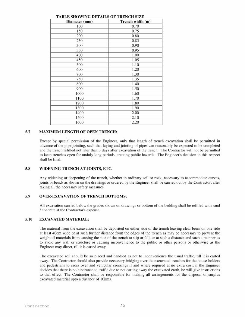
5.5 WIDTH OF TRENCH:
The width of the trench at bottom between the faces of sheeting shall be Nominal diameter of the pipe plus
300mm clearance on either side of the pipe. Trenches shall be of such extra width, when required as will permit
the convenient placing of timber supports, strutting and planking and handling of specials.
The width of trenches measured at the crown of the pipe shall permit adequate working space. The trenches
shall be widened at sockets and other structures as may be found necessary. Payment for excavation shall be
made on quantity basis as per width given in the Table.
Care should be taken to avoid excessive trench width and thereby increasing the load on the pipes.
5.6 DEPTH OF EXCAVATION OF TRENCHES:
The depths for the trenches will be calculated from the surface to the bed of the pipes and in case when a layer
of bedding is to be placed below the pipeline, the depth to the bottom of the bedding will be paid.
The trench shall be so dug that the pipeline may be laid to the required gradient and to the required depth,
mentioned in the Table below. A minimum cover of 1.2m is to be provided above the crown level of pipe upto
the Ground level / Road level.
Contractor 20
TABLE SHOWING DETAILS OF TRENCH SIZE
Diameter (mm) Trench width (m)
100 0.70
150 0.75
200 0.80
250 0.85
300 0.90
350 0.95
400 1.00
450 1.05
500 1.10
600 1.20
700 1.30
750 1.35
800 1.40
900 1.50
1000 1.60
1100 1.70
1200 1.80
1300 1.90
1400 2.00
1500 2.10
1600 2.20
5.7 MAXIMUM LENGTH OF OPEN TRENCH:
Except by special permission of the Engineer, only that length of trench excavation shall be permitted in
advance of the pipe jointing, such that laying and jointing of pipes can reasonably be expected to be completed
and the trench refilled not later than 3 days after excavation of the trench. The Contractor will not be permitted
to keep trenches open for unduly long periods, creating public hazards. The Engineer's decision in this respect
shall be final.
5.8 WIDENING TRENCH AT JOINTS, ETC.
Any widening or deepening of the trench, whether in ordinary soil or rock, necessary to accommodate curves,
joints or bends as shown on the drawings or ordered by the Engineer shall be carried out by the Contractor, after
taking all the necessary safety measures.
5.9 OVER-EXCAVATION OF TRENCH BOTTOMS:
All excavation carried below the grades shown on drawings or bottom of the bedding shall be refilled with sand
/ concrete at the Contractor's expense.
5.10 EXCAVATED MATERIAL:
The material from the excavation shall be deposited on either side of the trench leaving clear berm on one side
at least 40cm wide or at such further distance from the edges of the trench as may be necessary to prevent the
weight of materials from causing the side of the trench to slip or fall, or at such a distance and such a manner as
to avoid any wall or structure or causing inconvenience to the public or other persons or otherwise as the
Engineer may direct, till it is carted away.
The excavated soil should be so placed and handled as not to inconvenience the usual traffic, till it is carted
away. The Contractor should also provide necessary bridging over the excavated trenches for the house-holders
and pedestrians to cross over and vehicular crossings if and where required at no extra cost; if the Engineer
decides that there is no hindrance to traffic due to not carting away the excavated earth, he will give instructions
to that effect. The Contractor shall be responsible for making all arrangements for the disposal of surplus
excavated material upto a distance of 10kms.
Contractor 21
5.11 PIPE BEDDING:
i) Bedding
The MS pipeline shall generally be laid in ordinary sandy soil for which no extra bedding shall be
provided. In such case, while doing the excavation, the bottom of the trench shall be prepared in a
manner so as to match the curvature of the pipe as far as possible subtending an angle of about 120o at
the centre of pipe. Wherever the bottom of the trench is of such a nature (i.e. decomposed rock/ hard soil/
boulder) which is likely in the opinion of the Engineer-in-Charge to cause damage to the pipe or coating
or an unsuitable material is encountered which cannot support the pipe, the contractor shall excavate the
trench to an additional depth below the required depth and shall refill to required level with suitable
material such as loose soil/excavated earth, to be approved by the Engineer-in-Charge. The bedding
thickness shall be not less than 20 cm under the barrel of the pipes. The complete pipe has to be covered
and surrounded by the same material as used for bedding so that a total cover of 30cm above the barrel
can be achieved. The excavated hard/dense soil can be refilled after bedding and covering of the pipe
with the loose soil/ excavated earth.
The bedding shall be compacted with a light hand rammer. Any reduction in thickness due to compaction
shall be made up by adding earth during ramming. For the purpose of the bedding under this item only
screened fine earth of grain size not larger than 2mm shall be used. The bedding material shall be clean,
uncoated and free form clay lumps, injurious amounts of dust, soft particles, organic matter, loam or
other deleterious substances.
During the work of providing bedding and laying the pipeline over it, loose material from the sides or
edges of the trench shall be prevented from falling inside the trench, by providing shoring and taking other
measures. Also where necessary, trench shall be kept dry by pumping out seepage water continuously.
ii) Concrete Bedding:
This type of bedding is as per the drawing appended with the tender document and is to be provided at
locations shown in the drawings or as specified by the Engineer. A concrete bedding using M15 grade
is to be adopted. The concrete work related to this specification is detailed in the specifications of
concrete and allied works.
5.12 EXCAVATION FOR APPURTENANCES:
Excavation in trenches for foundation of valve chambers, pedestals etc. shall be as per the plan or as directed by
the Engineer. The dimensions of the excavation shall be measured as the projection in plan of the outermost
edges of the structure.
5.13 KEEP EXCAVATION CLEAR OF WATER:
Where ground water is encountered or anticipated, the Contractor shall provide sufficient pumps to handle the
ingress of water and must provide and maintain in working order. Standby pumping units are to be made
available and employed in the event of mechanical failure. The Contractor must also arrange for night and day
operation of the pumps wherever necessary to ensure that the work proceeds at all times.
5.14 DEWATERING IN AREAS OF HIGH WATER TABLE:
The Contractor shall perform dewatering as required so that all works of the contract are installed on dry areas
and excavations, including without limitation the construction of all structures and underground piping. The
Contractor shall ensure that dewatering is carried out only to a depth sufficient for the required excavation. The
Contractor shall also ensure that, at all times, during construction, no groundwater shall come into contact with
any concrete surface or reinforcement and that any structure shall be capable of withstanding any hydrostatic
pressure to which it may be subjected during construction and until completed.
The Contractor shall be deemed to have included in the tender price for maintaining all works in a dry condition
during construction. Any water removed from excavations shall wherever practicable, be pumped directly to
the natural drainage channel or to storm sewers if approved via an efficient system of discharge lines. No water
may be discharged into the sewerage system or onto open spaces.
The Contractor shall include for the diversion of all water courses encountered in the work until the scheme is
completed and put into operation.
Contractor 22
Notwithstanding any previous approval, the Contractor shall be fully responsible for maintaining dry
excavations.
Where deemed necessary by the Engineer, working drawings and data shall be submitted for review or approval
showing the intended plan for dewatering operations. Details of locations and capacities of dewatering wells,
well points, pumps, sumps, collection and discharge lines, standby units, water disposal methods, monitoring
and settlement shall be included. These shall be submitted not less than 30 days prior to start of dewatering
operations.
The static water level shall be drawn down to a minimum of 300mm below the bottom of the excavation so as
to maintain the undisturbed state of the foundation soils and allow the placement of any fill or backfill to the
required density. The dewatering system shall be installed and operated so that the groundwater level outside
the excavation is not reduced to the extent that would damage or endanger adjacent structures or property.
5.15 UNSOUND FOUNDATIONS, SOFT SPOTS:
When the specified levels of trench or structure are reached, the Engineer will inspect the ground exposed and if
he considers that any part of the ground is by its nature unsuitable, he may direct the Contractor to excavate
further and the further excavation shall be filled with concrete M-10 or river sand. Should the bottom of any
trench or structure excavation, while acceptable to the Engineer at the time of his inspection subsequently
become unacceptable due to exposure to weather conditions or due to flooding or have become puddled, soft or
loose during the progress of the works, the Contractor shall remove such damaged, softened or loosened
material and excavate further by hand. In this case, the cost of the extra excavation and of the additional
foundation materials required will be the Contractor's responsibility if necessitated by his negligence.
The omission by the Engineer to give an instruction under this Clause shall not relieve the Contractor from any
responsibility for defect in the works due to the construction being placed upon an unsuitable formation if prior
to the construction of the work the Contractor shall have failed to call the attention of the Engineer thereto in
writing.
If in the opinion of the Engineer, a formation is unsound as a result of the Contractor failing to keep the
excavation free from water, the Engineer will order the removal and disposal of the unsound material and filling
of the resulting void. The Contractor shall execute the work as directed and shall have no claim against the
Corporation for any costs thus incurred.
5.16 CAUTION CUM INFORMATION BOARDS:
Before commencing an excavation, "Caution-Cum-Information" board shall be installed at site by the
Contractor. Such board shall remain at site as long as the trench remains open. The board shall be installed at
both the ends of the trench atleast 100m before the approach to the area, if the trench is less than 600m in
length. Additional boards at every 300m shall be installed, if the length of the trench exceeds 600m. If the
streetlight is inadequate, lettering with fluorescent paint shall be used for these boards. The boards shall also
contain information regarding dates of commencement and completion of the work, name and phone number of
the Engineer in charge of the work. See also Clause 5.19. The size of lettering shall be adequate to be read by
passing vehicles.
5.17 BARRICADING:
To prevent persons from injury and to avoid damage to the property, adequate barricades, construction sign,
torches, red lanterns and guards as required shall be provided and maintained during the progress of the
construction work and until it is safe for traffic to use the roadways. The manhole trench shall be barricaded on
all four sides. Barricading for laying pipe lines consists of fixing casuarina posts 8 - 10cm dia. and 1.52m high
at 1.53m centre to centre tied with coir ropes in two rows or by any other method as approved by the Engineer.
Barrication also includes watching during night, fixing danger flags, danger lights / reflector and painting in
different colours. The Contractor who has dug up the trench shall be responsible for any mishap, which may
occur.
5.18 FENCING, WATCHING, LIGHTING:
The parts of the fencing shall be of timber, securely fixed in the ground not more than 2.50m apart, they shall
not be less than 10cm in dia. or not less than 1.25m above the surface of the ground. There shall be no two
Contractor 23
rails, one near the top of the posts and the other about 0.50m above the ground and each shall be of 5cm to
10cm in diameter and sufficiently long to run from post to post to which they shall be tied with strong ropes.
The method of projecting rails beyond the posts and tying together where they meet will not be allowed on any
account. All along the edges of the excavated trenches, a bund of earth about 1m high shall be formed when so
required by the Engineer for further protection. Proper provision shall be made for lighting at night and
watchmen shall be kept to see that this is properly done and maintained. In addition to the normal lighting
arrangements, the Contractor shall provide, whenever such work is in progress, battery operated blinking lights
(6 volts) in the beginning and end of a trench with a view to provide suitable indication to the vehicular traffic.
The Contractor shall also provide and display special boards printed with fluorescent prints indicating the
progress of work along the road. In the event of the Contractor not complying with the provisions of the clause,
it may be carried out by the Engineer and the cost recovered from the Contractor besides claiming liquidity
damages from the Contractor. In all such cases the work may be carried out by Corporation. The Contractor
shall be held responsible for all claims for compensation as a result of accident or injury to persons / non-
provision of red flags.
The Contractor shall at his own cost provide all notice boards before opening of roads as directed by the
Engineer.
Arrangements shall be made by the Contractor to obtain permission from SMC and traffic authorities for
working and to direct traffic when work is in progress. No separate payment shall be paid for this item of work.
5.19 REFILLING TRENCHES:
With a view to restrict the length of open trenches, on completion of the pipe laying operations, refilling of
trenches shall be started immediately by the Contractor. Pipe laying and testing shall follow closely upon the
progress of trench excavation and the Contractor shall not be permitted more than 500 metres of trench
excavation to remain open while awaiting testing of the pipe line.
Care shall be taken while back filling, not to injure or disturb the pipe. Filling shall be carried out
simultaneously on both the sides of the pipes so that unequal pressure does not occur.
Walking or working on the completed pipelines shall not be permitted unless the trench has been filled to a
height of at least 30cm over the top of the pipe except as may be necessary for tamping etc., during back filling
work.
Filling-in shall be done in layers not exceeding 150mm in thickness accompanied by adequate watering,
ramming etc. so as to get good compaction upto 300mm above the top of the pipe. Above this level, sea sand
shall be placed in layers of 200mm watered and compacted by tamping.
The trench shall be refilled so as to build up to the original ground level, keeping due allowance for subsequent
settlement likely to take place.
Before and during the backfilling of the trench, precautions shall be taken against the floatation of the pipeline
due to the entry of large quantities of water into the trench causing an uplift of the empty or the partly filled
pipeline.
5.20 MEASUREMENT AND PAYMENT:
The payment of excavation shall be made on quantity basis as per the actual dimensions of the trench excavated
limited to the width as per specification drawings.
Trench Excavation:
The length of the trench excavation shall be measured along the center line of pipe at various depths stated in
the Bill of Quantities, the total length being segregated into stretches according to the various depths of
excavation contained in the Bill of Quantities to fall into the specified categories. Within each stretch, the depth
applicable shall be within the range specified in Bill of Quantities.
The depth of excavation shall be measured from the top of the trench at the center before excavation upto the
bottom of the bedding under the pipe. If no bedding is provided, the measurement shall be to the top level of
the bottom of the pipeline. The width of the trench shall be measured on the basis of the specification drawing.
No additional payment shall be made for the deepening and widening at sockets specials, hunching or surrounds
Contractor 24
beyond the dimensions mentioned in the specification drawing. For excess width excavated the road cutting
charges to be paid by the Contractor.
The measurement of depth and width of trench shall be taken at every 20 metres along the alignment and at
every change in direction and diameter of the pipe.
Structure:
Measurement for structure excavation shall be made as per the projection in plan of the outermost edges of the
structure as per the plan at the bottom.
Rock excavation:
The depth of rock excavation measured for payment shall not exceed the corresponding depth in ordinary
excavation plus 150mm both for structure and trench excavations.
The maximum trench widths measured for payment in rock excavations will be as per specification drawing.
In all above cases, no payment will be made for additional selected fill, lean concrete, bedding cradling or
hunching concrete that may be specified or ordered by the Engineer as a consequence of excavating beyond the
limits specified in the contract documents or ordered by the Engineer.
Disposal of excavated material:
All the excavated material shall be carted away and the contractor shall be paid in the following manner for
disposal of the same. An item is provided in the bill of quantities and it includes loading, unloading,
transporting to a site upto a distance of 10kms as directed by the Engineer.
For excess width of excavation than specified, no payment will be made and the Contractor has to bear the cost
of restoration.
5.21 PERMANENT REINSTATEMENT:
Highways:
Restoration and re-instatement of Highways head and sidewalk surface shall be done by Highway Department
and CMWSS will pay the cost.
Municipal Roads: The reinstatement of the Municipal roads, i.e. Asphalt and WBM roads and side walk surface will be carried out
by the Municipal Roads Department of the Salem Municipal Corporation or by the Highways Department and
SALEM CORPORATION will pay the cost.
Private properties: However, any damages to the private properties such as compound wall, fencing, etc. during the execution or
immediately afterwards due to contractor carelessness, the same has to be restored by the Contractor to the
original shape at Contractor's own cost.
5.22 SHORING AND STRUTTING:
Open cuttings and trenches shall be suitably shored, sheeted and braced, if required by the Engineer or by site
conditions or to meet local laws, for protecting life, property of the work.
Adequate shoring and strutting shall be provided by the Contractors at their own cost. Warped or deformed
timber shall not be used. The shoring shall project at least 150mm above ground level and shall extend to a
suitable depth below the bottom of the trench. Wherever necessary, the planks or struts shall be driven by
compressed air pile drivers. The planks shall be fixed close enough to avoid any running in of sand earth
through the joints. The shoring material shall not be of sizes less than those specified below, unless steel sheet
piling is used or unless approved by the Engineer in writing.
a) Planks : 38mm thick
b) Walling pieces : 100 cm x 100 cm
c) Struts : 15 cm x 20 cm
Contractor 25
For walling pieces round timber shall not be allowed. In a vertical plane, there shall be at least three struts or
more as directed by the Engineer. They shall rest on walling pieces. The spacing of the struts shall be as per
the requirement of the design. At the bottom, extra struts shall have to be provided if ordered by the Engineer.
The rates for excavation do not include the cost of shoring, which shall be paid for separately as per relevant
item of the Bill of Quantities. The Contractors shall be held responsible for providing secure shoring, and for
adopting every other precaution, which may be necessary for protecting nearby structures, which are likely to be
damaged as a result of excavation. The Contractors shall design the shoring required for actual site conditions
and shall provide shoring accordingly. The design shall be submitted to the Engineer on demand. The shoring
shall be so designed that lowering of pipe of normal length or any other pipe laying operation does not
necessitate the removal of any strut or any other member of shoring. If the Engineer requires the adoption of
any special measures or precautions, the Contractor will comply with the same immediately. If any part of a
nearby structure is cut out or removed for facility of work, the same shall be made good on completion of the
work by the Contractors at their cost.
In the event of the Contractors not complying with the provisions of this contract in respect of shoring the
Engineering may, with or without notice to the Contractors, put up shoring or improve shoring already put up or
adopt such other measures as he may deem necessary, the cost of which shall be recovered from the
Contractors. Such action on the part of the Engineer, shall not, however absolve the Contractors of their
responsibilities under this contract.
No part of the shoring shall, at any time, be removed by the Contractors without obtaining permission from the
Engineer. While taking out shoring planks, the hollows formed shall be simultaneously filled in with soft earth
and shall be well compacted as directed.
No payment will be made if the Contractors leave shoring material in the trench on his own or merely to suit
their own convenience. The work of providing shoring shall be measured and paid for one the basis of areas of
planks provided upto ground level and no separate payment will be made for providing and fixing of walling
pieces, struts, dog spikes etc. the cost of which shall be deemed to have been covered by the rate for shoring.
The planks shall project at least 150mm above the ground level. For the purpose of payment, however,
measurements shall be taken up to ground level only and no payment will be made for planking above ground
level.
6.0 BRICK WORK
6.1 BRICK WORK:
Masonry Mortars:
Proportioning:
Mix proportion of cement sand mortar shall be as indicated. The mixes specified are by volume. 50 kg. of
cement shall be taken as equal to 0.035 cum. to determine bulk. The quantity of water to be added to cement
sand mortar shall be such that working consistency is obtained. Excess water shall be avoided.
Preparation of Cement Mortar:
Mixing shall be done preferably in a mechanical mixer. If done by hand, mixing operation shall be carried out
on a clean watertight platform. Cement and sand shall be mixed dry in the required proportion to obtain a
uniform colour. The required quantity of water shall then be added and the mortar hoed back and forth for 5 to
10 minutes with additions of water to a workable consistency. In the case of mechanical mixing, the mortar
shall be mixed for atleast three minutes after addition of water. Cement mortar shall be freshly mixed for
immediately use. Any mortar, which has commenced to set, shall be discarded and removed from the site.
Time of use of Mortar:
Mortars with cement as an ingredient shall be used as early as possible after mixing, preferably within half and
hour from the time water is added to the mix or at the latest within one hour of its mixing.

Contractor 26
Workability of Masonry Mortar:
The working consistency of the mortar is usually judged by the work during application. The water used shall
be enough to maintain the fluidity of the mortar during application, but at the same time it shall not be excessive
leading to segregation of aggregates from the cement.
Brick Masonry:
Manufacture:
Common burnt clay building bricks shall conform to the requirements of IS: 1077 and shall be of quality not
less than class 20 with moisture absorption rate not exceeding 15 percent as defined in IS:1077. The bricks
shall be chamber burnt and shall have sharp corners and smooth faces and shall not be damaged in any manner
and sizes shall conform to the works sizes specified with tolerances as given in 6.2 IS: 1077.
Samples:
The Contractor shall deliver samples of each type of brick to the Engineer, and no orders shall be placed
without the written approval of the Engineer. All the bricks used in the works shall be of the same standard as
the approved samples. The samples shall be preserved on site, and subsequent deliveries shall be checked for
uniformity of shape, colour and texture against the samples. If in the opinion of the Engineer any deliveries
vary from the standard of the samples, such bricks shall be rejected and removed from the site. Samples of
bricks shall be tested in accordance with IS: 3495 by the Contractor.
Uniformity:
The bricks selected for exposed pointed brickwork walls shall be of uniform colour, deep cherry red or copper
colour, and uniform texture. Only such bricks as are permitted by the Engineer shall be used.
6.2 SETTING OUT:
All brickworks shall be set out and built to the respective dimensions, thickness and heights as indicated.
6.3 SCAFFOLDING:
Scaffolding shall be strong to withstand all dead, live and impact loads, which are likely to come on them.
Scaffolding shall be provided to allow easy approach to every part of the work overhand work shall not be
allowed.
For exposed brick facing double scaffolding having two sets of vertical supports shall be provided. For
brickwork, which is to be plastered over, single scaffolding may be provided. In single scaffolding one end of
the putlogs shall rest in the hole provided in the header course of brick masonry. Not more than one header for
each putlog shall be left out. Such holes shall not be allowed in the case of pillars of narrow masonry portions
between openings, which are less than one metre in width or are immediately under or near the structural
member supported by the walls. The holes left shall be made good on removal of scaffolding to match with the
face work / surrounding area.
Timber or bamboo scaffolds shall be erected in accordance with the provisions contained in IS: 3696 (Part I) -
1987. Safety code for scaffolds and ladders, Part I - Scaffolds, to ensure safety of workmen and others. Steel
scaffolding shall be erected in accordance with the provisions contained in IS: 2750-1964. Specifications for
steel scaffolding and relevant provisions of IS: 3696 (Part I) - 1987 for safety code for scaffolds (Parts I & II)
and ladders shall be followed.
6.4 SOAKING OF BRICKS:
Bricks shall be soaked in water before use for a period of the water to just penetrate the whole depth of the
bricks. Alternatively bricks may be adequately soaked in stacks by profusely spraying with clean water at
regular intervals for a period not less than six hours. The bricks required for masonry work using mud mortar
shall not be soaked. When bricks are soaked, they shall be removed from the tank sufficiently early so that at
the time of laying they are skin-dry. Such soaked bricks shall be stacked-on clean place, where they are not
again spoiled by dirt, earth, etc.
Contractor 27
6.5 LAYING:
All loose materials, dirt and set lumps of mortar which may be laying over the surface on which brickwork is to
be freshly started, shall be removed with a wire brush and surface wetted slightly. Bricks shall be laid on a full
bed of mortar. When laying, the bricks shall be properly bedded and slightly pressed with handle of trowel so
that the mortar can get into all the pores of the brick surface to ensure proper adhesion. All the joints shall be
properly flushed and packed with mortar so that no hollow spaces are left. Care shall be taken to see that the
required quantity of water is added to the mortar at the mixing platform to obtain required consistency.
Addition of water during laying of the course shall not be permitted. In the case of walls two bricks thick and
over, the joints shall be grouted at every course in addition to bedding and flushing with mortar.
Bricks shall be laid with frog up. However if the top course is exposed, bricks shall be laid with frog down.
Care shall be taken to fill the frogs with mortar before embedding the bricks in position.
All quoins shall be accurately constructed and the height of courses checked with storey rods as the work
proceeds. Acute and obtuse quoins shall be bonded, where practicable, in the same way square quoins; obtuse
quoins shall be formed with squint showing a three quarter brick on one face and quarter brick on the other.
6.6 BOND:
All brickwork shall be built in English Bond, unless otherwise indicated. Half brick walls shall be built in
stretcher bond. Header bond shall be used for walls curved on plan for better alignment. Header bond shall
also be used in foundation footings, stretchers may be used when the thickness of wall renders use of headers
impracticable. Where the thickness of footings is uniform for a number of course of the footings shall be
headers.
Half or cut bricks shall not be used except where necessary to complete the bond.
Overlap in stretcher bond is usually half brick and is obtained by commencing each alternate course with a half
brick. The overlap in header bond which is usually half the width of the brick is obtained by introducing a three
quarter brick in each alternate course at quoins. In general, the cross joints in any course of brickwork shall not
be nearer than a quarter of brick length from those in the course below or above it.
6.7 UNIFORMITY:
The brickwork shall be built in uniform layers; corners and other advanced work shall be raked back. No part
of a wall during its construction shall be raised more than one metre above the general construction level, to
avoid unequal settlement. Parts of walls left at different levels shall be properly raked back. Toothing may be
done where future extension is contemplated but shall not be used as an alternative to taking back.
For half brick partition to be keyed into main walls, indents shall be left in the main walls.
6.8 THICKNESS OF JOINTS:
The thickness of joints shall be 10mm + 3 or – 3mm, unless otherwise specified. Thickness of joints shall be
kept uniform. Slight difference to thickness of bricks shall be adjusted within joint thickness. Where brickwork
is to match the existing work, the joints shall be of the same thickness as in the existing work.
6.9 STRIKING JOINTS:
Where no pointing, plastering or other finish is indicted, the green mortar shall be neatly struck flush. Where
pointing, plastering or other finish is indicated, the joints shall be squarely raked out to a depth not less than
10mm for plastering and 15mm for pointing.
6.10 CURIN
The brickwork shall be constantly kept wet for atleast 7 days.
Contractor 28
6.11 FACING:
In case of walls one brick thick and under, atleast one face shall be kept even and in proper plane, while the
other face may be slightly rough. In case of walls more than one brick thick, both the face shall be kept even
and in proper plane.
For exposed brickwork selected bricks of the specified class and sub-class shall be used for the face work,
where however, use of facing bricks is indicated, brick walls shall be faced with facing bricks. No rubbing
down of brickwork shall be allowed.
Brick walls shall be plastered pointed or otherwise finished, as indicated. Joints of external faces of brick walls
in foundation upto 15cm below ground level and of internal faces of brick walls in foundation and plinth below
sub-floor level shall be struck flush when the mortar is green, as the work proceeds.
6.12 CLEANING:
Face of brickwork shall be cleaned on the same day it is laid and all mortar droppings removed.
6.13 CONSTRUCTION DETAILS:
Holes for Pipes etc.
All necessary holes for pipes, air flues, ventilators, etc. shall be cut or formed as work proceeds and grouted in
cement and sand mortar 1:3 of cement concrete 1:2:4 as required and made good.
7.0 CONCRETE WORKS
7.1 CONCRETE:
General:
a. The quality of materials and method and control of manufacture and transportation of all concrete
work irrespective of mix whether reinforced or otherwise, shall conform to the applicable portions of
this Specification.
b. The Engineer shall have the right to inspect the source/s of materials, the layout and operation of
procurement and storage of materials, the concrete batching and mixing equipment, and the quality
control system. Such an inspection shall be arranged and Engineer’s approval obtained, prior to
starting of concrete work.
7.2 MATERIALS FOR STANDARD CONCRETE:
The ingredients to be used in the manufacture of concrete shall consist solely of Portland cement, clean sand,
natural coarse aggregate, clean water, and admixtures, if Specifically called for and conditions at site warrant its
use.
a. Cement: Cement shall conform to IS: 12269 – 1987.
b. Aggregates: Aggregates shall comply with the requirements of IS: 383 – 1970.
i. General
a) “Aggregate” in general designates both fine and coarse inert materials used in the manufacture of
concrete.
b) “Coarse Aggregate” is aggregate most of which is not passed through on 4.75mm IS sieve.
c) “Fine aggregate” is aggregate most of which is passed through on 4.75mm IS sieve.
d) All fine and coarse aggregate proposed for use in the works shall be subject to the Engineer’s
approval and after specific materials have been accepted, the source of supply of such materials
shall not be changed without prior approval of the Engineer.
e) Aggregates shall, except as noted above, consist of natural sands, crushed stone from a source
known to produce satisfactory aggregate for concrete and shall be chemically inert, strong, hand,
Contractor 29
durable against weathering of limited porosity and free from deleterious materials that may cause
corrosion of the reinforcement or may impair the strength and or durability of concrete. The
grading of aggregates shall be such as to produce a dense concrete of specified strength and
consistency that will work readily into position without segregation and shall be based on the
“mix design” and preliminary tests on concrete specified later.
f) Aggregates having a specific gravity below 2.6 (saturated surface dry basis) shall not be used
without the special permission of the Engineer.
ii. Fine Aggregate:
a) General:
Fine aggregate shall consist of natural or crushed sand conforming to IS: 383. The sand shall
be clean, sharp, hard, strong and durable and shall be free from dust, vegetable substances,
adherent coating, clay, alkali, organic matter, mica, salt or other deleterious substances, which
can be injurious to the setting qualities / strength / durability of concrete.
(i) Machine-made Sand: Machine-made sand will be acceptable, provided the
constituent rock-gravel composition shall be sound, hard, dense, non-organic,
uncoated and durable against weathering.
(ii) Screening and Washing: Sand shall be prepared for use by such screening or
washing, or both, as necessary, to remove all objectionable foreign matter while
separating the sand grains to the required size fraction.
(iii) Foreign material limitations: The percentage of deleterious substances in sand
delivered to the mixer shall not exceed the following:
Percent by weight:
Uncrushed Crushed
(A) Material finer than 75 micron I.S. Sieve 3.00 15.00
(B) Shale 1.00 --
(C) Coal and lignite 1.00 1.00
(D) Clay lumps -- --
(E) Total of all above substances including items
(A) to (D) for uncrushed sand and items (C) and
(D) for crushed sand
5.00 1.00
b) Gradation:
(I) Unless otherwise directed or approved by the Engineer, the grading of sand shall be within the
limits indicated under here:
Percentage passing for IS Sieve
Grading Grading Grading Grading
Designation Zone – I Zone – II Zone – III Zone AVE
10mm 100 100 100 100
4.75mm 90 – 100 90 – 100 90 – 100 95– 100
2.36mm 60 – 95 75 – 100 85 – 100 95 – 100
1.18mm 30 – 70 55 – 90 75 – 100 90 – 100
600micron 15 – 34 35 – 59 60 – 79 80 – 100
300micron 5 – 20 8 – 30 12 – 40 15 – 50
150micron 0 – 10 0 – 10 0 – 10 0 - 15
(II) Where the grading falls outside the limits of any particular grading zone of sieves, other than
600 micron I.S. sieve, by total amount not exceeding 5 percent, it shall be regarded as falling
within that grading zone. This tolerance shall not be applied to percentage passing the 600
micron I.S. sieve or to percentage passing any other sieve size on the coarser limit of Grading
Zone I or the finer limit of Grading Zone AVE. Fine aggregates conforming to Grading Zone
AVE shall be used. Mix designs and preliminary tests shall show its suitability for producing
concrete of specified strength and workability.
Contractor 30
c) Fineness Modulus:
The sand shall have a fineness modulus of not less than 2.2 or more than 4.2. The fineness
modulus is determined by adding the cumulative percentages retained on the following I.S.
sieve sizes (4.75mm, 2.36mm, 1.18mm, 600micron, 300micron and 150micron) and dividing
the sum by 100.
(iii) Coarse Aggregate:
a) Coarse aggregate for concrete, except as noted above, shall conform to IS: 383. This
shall consist of crushed stone and shall be hard, strong, durable clean and free from
elongated, flaky or laminated pieces, adhering coatings, clay lumps, coal residue,
clinkers, slag, alkali, mica, organic matter or other deleterious matter.
b) Screening and Washing:
Crushed rock shall be screened and or washed for the removal of dirt or dust coating,
if so requested by the Engineer.
c) Grading:
Coarse aggregate shall be either in single size or graded, in both cases the grading
shall be within the following limits.
Percentage passing for single sized
aggregate of normal size
Percentage passing for graded
aggregate of normal size
IS Sieve
Desig- nation 40
mm
20
mm
16
mm
12.5
mm
10
mm
40
mm
20
mm
16
mm
12.5
mm
63 mm 100 -- -- -- -- 100 -- -- --
40 mm 85
100
100 -- -- -- 95
100
-- -- --
20 mm 0
20
85
100
100 -- -- 30
70
95
100
100 --
16 mm -- -- 85
100
100 -- -- -- 90
100
--
12.5 mm -- -- -- 85
100
100 -- -- -- 90
100
10 mm 0
5
0
20
0
30
0
45
85
100
10
35
25
35
30
70
40
85
d. Water: Water for mixing concrete, mortar or grout shall conform to IS:456 – 2000. If
required to do so by the Engineer, the Contractor shall take samples of the water and test them
for quality.
7.3 TRANSPORTING AND DEPOSITING CONCRETE:
Mixing plant shall be located as close as possible to the point of placement. Concrete shall be placed within 30
minutes after mixing and shall be transported from the mixer to its final placement as rapidly as practicable,
taking care to see that no segregation or loss of ingredients take place. It shall also be ensured that the concrete
is of the required workability at the point and time of placing.
Dropping of concrete from an excessive height or running or working it along forms will not be permitted. Any
concrete which, before placement has begun to set and has become stiff shall be rejected.
Concrete shall not be disturbed after it has been placed in the form and has begun to set. Concrete shall be
carefully placed in horizontal layers which shall be kept at an even height throughout the work. Concrete shall
not be allowed to slide or flow down sloping surfaces directly into its final position but shall be placed in its
final position form the skips, trucks, barrows, down pipes or other placing machines or device or, if this is
impossible it shall be shoveled into position, care being taken to avoid separation of the constituent materials.
Concrete placed in horizontal slabs from barrows or other tipping vehicles shall be tipped into the face of the
previously placed concrete.
Concrete dropped into place in the work shall be dropped vertically. It shall not strike the formwork between
the point of its discharge and its final place in the work and except by approval of the Engineer, it shall not be
dropped freely through a height greater than 1.5 metres. Chutes & Conveyor belts shall be so designed that
Contractor 31
there is no segregation or loss of mortar and shall be provided with a vertical tapered down pipe or other device
to ensure that concrete is discharged vertically into place.
Where a lift of concrete is built up in layers each layer shall be properly merged into the proceeding layer before
initial set takes place.
7.4 QUALITY ASSURANCE
General Procedure:
A. General:
In order to achieve the required strength and associated properties of concrete, proper control of the Water /
Cement ratio by weight need be enforced. The strength shall be prime consideration and W.C. ratio as
prescribed by Engineer in charge shall have to be observed.
B. Operators:
At no time whatsoever will the mixer operator or those supervising or inspecting the works be permitted to alter
the quantity of water specified by the Engineer for mixing the concrete. Batching shall be accurate and as
specified by the Engineer.
C. Water / Cement Ratio:
The Water / Cement ratio will be determined after mix trials by the Contractor in the presence of the Engineer
or his representative. If batching is by volume, the Contractor shall be required to fabricate such volumetric
batches and water containers as the Engineer may determine and require so as to simulate the ideals of the trial
mix without recourse to assessments by site staff and workmen.
D. Weighing:
The Contractor shall make available always a weighing machine if so required, guaranteed by the Contractor for
its accuracy, for weighing cement and batches of aggregate as and when the Engineer or his representative or
his assistant may require. The machine shall be capable of weighing upto 75 Kilograms and shall be accurate to
half (0.5) Kilogram.
E. Compaction:
All concrete shall be thoroughly compacted and fully worked round the reinforcement by vibration just
sufficiently so that the appearance of laitance is kept to a minimum and in such manner as directed by the
Engineer’s Representative. Under no circumstances shall concrete be compacted by trowels or the like.
F. Transport and Placing:
Fresh concrete from the mixer shall be transported where required by the quickest and most efficient means so
as to prevent pre-set or segregation or any loss of ingredients and shall maintain required workability. Any
laitance from previous mixes shall be removed.
7.5 SAMPLING, TESTING AND STORAGE OF MATERIALS:
Samples of aggregates for mix design and determination of suitability shall be taken under the supervision of
Engineer and delivered to the laboratory well in advance of the scheduled placing of concrete. Records of tests
made on proposed aggregates and on concrete made from this source of aggregates shall be furnished to the
Engineer in advance of the work for use in determining aggregate suitability. The cost of all such tests,
sampling etc. shall be borne by the Contractor.
Materials shall be tested as hereinafter specified and unless specified otherwise, all sampling and testing shall
be performed by Testing Laboratory approved by Corporation at the Contractor’s expense.
Contractor 32
A. Cement:
Cement shall, whether supplied by the Corporation or not, comply with the requirements of IS: 8041, IS: 455,
IS: 8043, IS: 6909, IS: 1489, IS: 12269. The testing laboratory at the discretion by the Engineer, shall perform
such tests as are deemed necessary. Cement bags or bulk silos shall be tagged for identification at location of
sampling. Tests will include tensile tests and weighing the cement supply to check for net weight received at
site and used in the works.
1. On arrival at site, cement shall be stored in weatherproof silos designed for the purpose or in dry
weather-tight and properly ventilated structures will floors raised 15 to 20cm above ground level,
30cm away from walls and with adequate provision to prevent absorption of moisture or flooding. All
storage facilities shall be subject to approval by the Engineer and shall be such as to permit easy access
for inspection and identification. Each consignment of cement shall be kept separately and the
Contractor shall use the consignments in the order in which they are received. Any cement in drums or
bags, which have been opened, shall be used immediately. Different types of cement shall be kept in
clearly marked separate storage facilities. Not more than 15 bags shall be stacked vertically in one
pile. Cement shall be stored in double locking arrangement, so that cement transactions can be with
the knowledge of supervisory staff. Daily account of cement shall be maintained by the Contractor in
the prescribed register and shall be made available to inspecting authorities for store verification.
2. The Contractor shall provide from each consignment of cement delivered to the site such samples as
the Engineer may require for testing. Any cement which is, in the opinion of the Engineer, lumpy or
partially set shall be rejected and the Contractor shall promptly remove such cement from the site.
3. Cement which has been stored on the site for more than ninety (90) days and cement which in the
opinion of the Engineer is of doubtful quality shall not be used in the works until it has been retested
and test sheets showing that it complies in all respects with the relevant standard have been delivered
to the Engineer.
B. Water for Concrete Mixing & Curing:
Water shall be clean, clear and free from injurious quantities of salt, traces of oil, acids, alkalies, organic matter
and other deleterious materials. The sources of water shall be approved by the Engineer and the containers for
conveyance; storage and handling shall be clean. If necessary, standard cement tests shall be conducted using
the water intended to be used, in comparison with those adding distilled water to check quality of water.
Water shall meet the requirement of 4.3 of IS: 456 – 2000. Generally potable water is fit for mixing and curing.
C. Aggregates:
Aggregate will be tested before and after concrete mix is established and whenever character or source of
material is changed. Tests will include a sieve analysis to determine conformity with limits of gradation.
1. Samples of aggregates 50 kg. in weight will be taken by the Contractor at source of supply and
submitted to the Engineer before placing orders. These samples if approved shall remain preserved in
the Engineer’s care for reference and the type of aggregate used in the works may not be altered
without Engineer’s prior approval.
2. Aggregate shall be obtained from an approved source and shall conform to the requirements of IS: 383.
For the aggregate grading, in table of IS: 383 – 1970 shall be applicable. Aggregate shall not be flaky
or elongated particles, defined as particles having a maximum dimension greater than five times the
minimum dimension. Aggregate shall have water absorption not exceeding two percent when tested in
accordance with IS 383.
3. The Contractor shall sample and carry out analysis in the presence of the Engineer’s representative, or
the fine aggregate and each nominal size of coarse aggregate in use employing the methods described
in IS: 383 and 2386 at least once in each week when concreting is in progress and such more frequent
intervals as the Engineer may require. The grading of all aggregates shall be within the respective
limits specified in the codes. For aggregates, which vary more than the approved fineness modulus,
the Engineer may instruct the Contractor to alter the relative proportions of the aggregate in the mix to
allow for such difference, or may require further trial mixes.
4. Storage of aggregates shall be provided at each point where concrete is made such that each nominal
size of coarse aggregate and the fine aggregate shall be kept separated at all times. Contamination of
the aggregates by the ground or other foreign matter shall be effectively prevented at all times, and
Contractor 33
each heap of aggregate shall be capable of draining freely. The Contractor shall ensure that graded
coarse aggregates are dumped, stored and removed from store in manner that does not cause
segregation.
Coarse aggregate shall be piled in layers not exceeding 1.2m in height to prevent coning or segregation. The
aggregates must be of specified quality not only at the time of receiving at site but more so as the time of
loading into mixer.
Wet fine aggregate shall not be used until, in the opinion of the Engineer, it has drained to a constant and
uniform moisture content, unless the Contractor with the knowledge of the Engineer measures the moisture
content of fine aggregate and adds water in each batch of concrete mixed to allow for the water contained in the
fine aggregate.
7.6 MIX DESIGN:
Mix design is normally a prerequisite to any concreting job and will be required on all major works. If so
required, an approved testing laboratory shall, at the Contractor’s expense, design a mix for each class of
concrete and shall submit full details of the mix designs to the Engineer for his approval. The Engineer’s
representative and the Contractor shall clearly code each approved mix with a number and date, and file all
details for identifying and reproducing exactly the same mix.
A. General:
Each mix design shall be such that the aggregate shall comprise fine aggregate and coarse aggregate of the size
specified and the combined aggregate grading shall be continuous. Aggregate shall be calculated by weight,
and batching procedures shall be established. The cement content by weight shall not be outside the minimum
and maximum limits calculated from the minimum and maximum dry aggregate to cement ratios specified. The
mixes shall be designed to produce average concrete cube strength at twenty eighth day after manufacture not
less than the trail mix test strength specified. The water / Cement ratio shall be in the region of 0.45 to 0.55 and
shall never exceed 0.60.
B. Preliminary Mix:
The proportions of cement, aggregate and water determined by the Contractor in his mix design shall be used in
preliminary mix of concrete made and tested for strength and workability under laboratory conditions observing
the appropriate requirements. These preliminary mixes shall be repeated with adjusted proportions as necessary
until concrete mixes meeting the requirements of the preliminary and trial mix tests specified and with the
workability defined herein have been produced. If at any time during construction of the works, the source of
cement or aggregates is changed, or the grading of the aggregate alters, then further preliminary mixes shall be
undertaken.
C. Trials:
After the Engineer’s approval of the preliminary concrete mix design for each class of concrete and during or
following the carrying out of the preliminary tests, the Contractor shall prepare a trial mix of each class in the
presence of the Engineer. The trial mixes shall be mixed for the same time and handled by means of the same
plant that the Contractor propose to use in the works. The proportion of cement, aggregates and water shall be
carefully determined by weight in accordance with the approved mix design (or modified mix design after
preliminary tests) and sieve analyses shall be made, by approved methods of the find aggregate and each
nominal size of coarse aggregate used.
D. Admixtures:
Admixtures shall mean material added to the concrete materials during mixing for the purpose of altering the
properties of normal concrete mixes. If the Contractor wishes to use admixtures, otherwise than as expressly
ordered by the Engineer, he shall first obtain the Engineer’s written permission. The methods of use and the
quantities of admixture used shall be subject to the Engineer’s approval, which approval or otherwise shall in no
way limit the Contractor’s obligations under the contract to produce concrete with the specified strength and
workability. Concrete of any class containing an admixture shall be separately designed and have separate
preliminary tests and trial mixes made and tested for approval by the Engineer as if it were a separate class of
concrete.

Contractor 34
Waiver of Mix Design and Weigh Batching:
On certain works, the Engineer may waive the requirement of designing mixes and may allow the use of
established nominal mix proportion, provided always that preliminary trials are made to establish the volumetric
batching procedure and mix strengths. The Contractor will ensure that any established procedure approved by
the Engineer is strictly adhered to, so as to achieve consistent strength, durability and economy of the concrete
while ensuring approved workability of the mix. Any waiver of mix design or weigh batching will not relieve
the Contractor of his obligations to consistently produce concrete of the specified and approved strength and
durability as determined by works tests. However in any particular work / part of work, the Engineer may
decide to adopt mix design (mix) concrete.
Workability:
The workability of each class of concrete shall be such that satisfactory compaction can be obtained when the
concrete is placed and vibrated in the works. There shall be no tendency to segregate when it is handled,
transported and compacted by the methods, which the Contractor proposes to use when handling, transporting
and compacting that class of concrete in the works.
Grades of concrete:
The concrete shall be in grades designed in Table 2 IS: 456 – 2000.
Concrete Mix Design:
Procedure for designing concrete mixes shall be as per IS: 10262 – 82. “Recommended guidelines for concrete
mix design”.
7.7 BATCHING:
Cement:
All cement used in making concrete shall be measured by weight either with an approved weighing machine or
by making the size of each batch of concrete such as to require an integral number of complete bags of cement
of weight consistent with the requirements of CI 9 of IS: 12269 - 1987. In case of ordinary mixes, the cement
bag shall be taken to be 50 kg. (35 litres).
Aggregate:
The find and coarse aggregate shall be measured separately either by volume in gauge boxes or by weight using
machines with weigh batching attachments. For high grave concrete, the fine aggregate shall be measured
singly or cumulatively by weight. The Engineer will rule on this requirement.
Gauge Boxes:
Gauge boxes shall be soundly constructed by the Contractor, with the approval of the Engineer and shall be of
timber or of steel to contain exactly the volume of the various aggregates required for one batch of each mix.
Each gauge shall be clearly marked with the mix code and the aggregate for which it is intended. When
calculating the size of the gauge box for fine aggregate, allowance shall be made for the bulking of the fine
aggregate due to the average amount of moisture contained in the stockpiles on the site. Before the Contractor
shall put any gauge box into use on the site, he shall obtain the approval of the Engineer of the size and
construction of such gauge box.
Water Container:
Containers for measuring water shall be soundly constructed of metal to contain the exact quantity of water
required for a batch of mix, due allowance having been made for the moisture content of the aggregates, or such
fractions of the quantity as are approved by the Engineer. Containers shall have spouts, the pill levels of which
determine the quantity. Fixed containers shall be elevated and have overflow pipes, which determine the
quantity held in the container, and shall have an outlet valve and hose fixed to the bottom of the container.
Before any container is put into use, the approval of the Engineer shall be obtained.
Contractor 35
Weigh-Batching:
Weigh batching machines shall provide facilities for the accurate control and measurement of the materials
either singly or cumulatively and shall be capable of immediate adjustment by operators in order to permit
variations if ordered by the Engineer. All weight dials shall be easily visible from the place at which filling and
emptying of the hoppers are controlled.
Addition of Water and Mixing:
A. Water:
The addition of water to a mixer shall be controlled such that between five and ten percent of the water
enters the mixer before the cement and aggregate and a further five to ten percent of water enters the
mixer after the said materials have been batched. The remainder of the water shall be added at a
uniform rate with the said materials. The water-measuring device shall also be readily adjustable so
that the quantity of water added to the mixer can, if necessary in the opinion of the witnessing
Engineer’s representative be varied. The natural moisture contents of the aggregates shall be
determined before the commencement of concreting or at such intervals as may be necessary or as
required by the Engineer. The Contractor shall make due allowance for the water contained in the
aggregate when determining in consultation with the Engineer’s representative, the quantity of water to
be added to each mix, and shall adjust the amount of water added to each mix to maintain consistently
the approved water / cement ratio of the mixed concrete. All important concrete shall be machine
mixed to give complete coating of cement mortar on each coarse aggregate particle and to produce
uniform coloured concrete with uniform distribution of materials. The mixer shall be run minimum 1
½ minutes. In case, for a minor job, hand mixing is permitted by the Engineer, it shall be done on
smooth watertight platform not allowing the added water to flow out. The fine aggregate shall be
spread in uniform thickness layer over which cement as required shall be placed and they shall be
mixed thoroughly to give dry mortar. Water is then added gradually in required proportion, turning the
mass, to give desired consistency mortar. The required quantity of coarse aggregate is then placed on
mixing platform, wetted and mortar added. The entire mass is turned and returned to give uniform
concrete of required consistency. 5% additional cement shall be used for hand mixed concrete.
B. Admixtures: Any admixtures approved by the Engineer, which may be used, shall be measured separately in
calibrated dispensers and shall be added to the mixture together with the water.
C. Uniformity of Mix:
Concrete shall be mixed in batches in plant capable of mixing the aggregates, cement and water
(including admixtures, if any) into a mixture uniform in colour and consistency and of discharging the
mixture without segregation.
D. Contractor’s Returns:
The Contractor shall render to the Engineer, daily return for each class of concrete of the number of
batches mixed, and total volume of concrete placed, the number of batches wasted or rejected and the
weight of cement used. In case of ordinary mixes, where permitted, the cement bags consumed for
quantities of various classes of concrete shall be furnished. In addition daily details of time of starting
concrete, closure, No. of batches through mixer, W.C. ratio, slump, date of striking form works etc.
shall be maintained. This day-to-day record shall be authenticated by responsible supervisory staff.
E. Plant and Equipment Generally: All mixing and batching plants boxes, containers and other equipment shall be maintained free of
defects or of set concrete or cement and shall be cleaned before commencing mixing. At such intervals
as may be directed by the Engineer, the Contractor shall provide weights, containers and equipment
necessary for testing the accuracy of the weighting plant, water measuring plant and admixture
dispenser.
7.8 CONCRETING:
Preparation:
The Contractor shall clear from the surface of the foundations or previously placed concrete all oil, loose
fragments of rock, earth, mud, timber and any other foreign matter and shall clear standing water and wash the
surface of a previous lift of concrete to the satisfaction of the Engineer.

Contractor 36
a. Laitance:
Where laitance on a lift of concrete is evident or if a substantial bond between this lift or bay or
concrete and the next is required, in the opinion of the Engineer’s representative, the Contractor shall
have the surface wire brushed after initial set of the concrete or have it bush-hammered at no extra cost
to the Corporation. Any reinforcing bars covered in laitance shall be wire brushed to clean the surface
of the metal.
b. Blinding: As ordered by the Engineer, or as shown on the drawings the formation surfaces on which concrete is
to be placed shall be covered with either blinding concrete not less than 75mm thick, or waterproof,
building paper, or polythene sheeting immediately after completion of the final trimming of the
excavation.
7.9 INSPECTION:
Concrete shall not be placed until the Engineer has inspected the formwork and the reinforcing steel, and taken
necessary measurements of the latter, and has approved the surface upon which the concrete is to be placed.
a. Transporting:
Fresh concrete shall be transported from the mixer to its place in the works as quickly and as
efficiently as possible by methods, which will prevent pre-set or segregation. If segregation has
nevertheless occurred in any instance, the materials shall be remixed or discarded at the opinion of the
Engineer.
b. Placing: Fresh concrete shall be placed and compacted before initial set has occurred and in any event, not later
than thirty minutes from the time of mixing. Concrete shall be carefully placed in horizontal layers
which shall not be allowed to slide or flow down sloping surfaces but shall be placed in its final
position from skips, or similar devices. If this is impracticable, it shall be shoveled into position care
being taken to avoid segregation. No concrete shall be dropped more than 1.5m. If greater drops are
necessary approved chutes may be used. If the concrete abuts against earth or any other material liable
to become loose or to slip, care shall be taken to avoid falls of materials on the surface of the wet
concrete.
As far as possible concrete for any particular portion shall be done in one continuous operation leaving
construction joints, if specified by drawing.
Before commencing subsequent concrete on the one left incomplete, all the loose particles, laitance
etc. shall be removed and surface shall be covered with thick cement slurry. The concrete compacted
manually shall be laid in layers not more than 15 to 20cm. The successive layer shall follow within 30
minutes or earlier.
7.10 COMPACTION:
All concrete placed in-situ shall be compacted with power driven or pneumatic internal type vibrators unless
otherwise approved by the Engineer in writing, and shall be supplemented by hand spading and tamping where
required. Vibrating by screed type vibrators may be used for thin slabs. There shall be sufficient and spare
vibrators of adequate capacity to compact the work in hand.
a. Vibration:
Vibrators shall be inserted into the uncompacted concrete vertically and at regular intervals. Where the
uncompacted concrete is in a layer above freshly compacted concrete, the vibrator shall be allowed to
penetrate vertically for about 75mm into the previous freshly compacted layer. The vibrators shall not
be allowed to come into contact with the reinforcement of formwork nor shall they be withdrawn
quickly from the mass of concrete but shall be drawn back slowly while in motion so as to leave no
voids. Internal type vibrators shall not be placed in the concrete in any arbitrary manner nor shall
concrete be moved from one part of the work to another by means of the vibrators. The vibrators shall
have minimum 3600 (preferably 5000) impulses per minute.

Contractor 37
b. Duration:
The duration of vibration shall be limited to that required to produce satisfactory compaction of the
concrete without causing segregation. Vibration shall an no account be continued after the appearance
of water or grout on the surface.
c. Hand compaction:
This shall be permitted exceptionally for small jobs by the Engineer. In such cases, compaction shall
be attained by means of rodding, tamping, ramming and slicing with suitable tools. The thickness of
concrete layers will also be suitably reduced when hand compaction is resorted to.
7.11 UNDER WATER CONCRETING:
No concrete shall be placed in water without the Engineer’s written permission, which may only be granted if in
his opinion it is not practicable to place the concrete in the dry. Concrete shall not be placed is running water
nor shall concrete be allowed to fall through water. Any water entering the area where concrete is being placed
shall, at the Contractor’s expense, be kept clear of the concreting works. If under water concreting is permitted,
the specified mix of concrete shall be strengthened by increasing the cement content by atleast 10.0% and
reducing the water / cement ratio to no more than 0.45, and the placing shall be only through a tremmie
approved by the Engineer. The volume or mass of the coarse aggregate shall not be less than 1 ½ times not
more than twice that of the fine aggregate. The material shall be so proportioned as to produce a concrete
having a slump of not less than 100mm and not more than 180mm.
7.12 CURING:
All concrete shall be protected from the effects of sunshine, rain, running water or mechanical damage and
cured by covering with jute, hessian or similar absorbent material kept constantly wet or a layer of sand kept
covered with water is also permissible for a continuous period of fourteen days at least from the date of
placement. Should the Contractor fail to water concrete continuously, the Engineer may provide labour and
materials required for curing and recover the cost from the Contractor.
7.13 FINISHING:
Immediately after removal of forms, any undulations, depressions, cavities, honey combing, broken edges or
corners, high spots and defects shall be made good and finished with C.M. 1:2, but the necessity of such
finishing must be exceptional and total surface requiring finishing shall not exceed 1%. Where concrete surface
is to receive plaster, the surface shall be roughened immediately after removal of forms and within a day thereof
to secure a hold for the plaster. The rate of concrete is inclusive of this roughening and finishing. Concrete
after finishing shall be cured for the full period.
7.14 JOINTS:
Construction Joints:
Construction joints are defined as joints in the concrete introduced for convenience in construction at which
special measures are taken at achieve subsequent continuity without provision for further relative movement.
a. Submittal:
No concreting shall be started until the Engineer has approved the methods of placing, the positions
and form of the construction joints and the size of lifts.
b. Jointing:
The face of a construction joint shall have all laitance removed and the aggregate exposed prior to the
placing of fresh concrete. The laitance shall wherever practicable be removed by spraying the concrete
surface with water under pressure and brushing whilst the concrete is still green. Where the laitance
cannot be removed whilst the concrete is green, the whole of the concrete surface forming part of the
joint shall be hacked to expose the aggregate. Where aggregate is damaged during hacking, it shall be
removed from the concrete face by further hacking. All loose matter shall be removed and the exposed
surface thoroughly cleaned by wire brushing, and washing down, and the surface to which fresh
concrete is applied shall be clean and damp.

Contractor 38
Expansion Joints:
Expansion joints are defined as joints intended to accommodate relative movement between adjoining
parts of a structure special provision being made where necessary for maintaining the water tightness
of the joint.
a. The joint location and type will be as indicated in the drawings.
1. The Contractor shall comply with the instructions of manufacturers of proprietary jointing
materials and shall, if required by the Engineer, demonstrate that the jointing materials can be
applied satisfactorily and will last the life of the structure.
2. Flexible water stops shall be fully supported in the formwork, free of nails and clear of
reinforcement and other fixtures. Damaged water stops shall be replaced and during concreting
care shall be taken to place the concrete so that water stops do not bend or distort.
b. Jointing:
The surface of set concrete shall not be disturbed and concrete shall be placed against the dry finished
surface.
3. If ingress of water or corrosive agents in the joint is possible, the steel, where such steel is
continued, shall be cleaned and coated with two coats of an approved bituminous paint to a
distance not exceeding 10mm.
4. Where specified, the surface of the set concrete shall be painted with two coats of an approved
bituminous paint, which shall be allowed to dry before placing new concrete against it. Care
shall be taken to prevent paint getting on the water stop, if any.
5. Expansion joints shall be formed by a separating strip of pre-formed compressible imperishable
joint filler, to be approved by the Engineer.
7.15 TESTING OF CONCRETE:
Sampling and strength test of concrete shall be as per 14 of IS: 456 – 2000.
8.0 FORM WORK
8.1 MATERIAL:
All formwork for concrete work shall be mostly of M.S. Plates. The plates shall be free from wrinkles, lumps
or other imperfections. Steel plates shall have sufficient thickness to withstand the construction loads and the
pressure exerted by the wet concrete as well as vibration during placing of concrete. Normally the thickness
shall not be less than 18 gauge for M.S. Plates.
The formwork may also be constructed of timber, or other approved material. It shall be firmly supported,
adequately strutted, braced and tied to withstand the placing and vibrating of concrete and the effects of
weather. One copy of the Contractors shoring and formwork drawings shall be submitted to the Corporation for
record purpose only and not for review or approval. Forms, shoring and false work shall be adequate for
imposed live and dead loads including equipment and men, height of concrete drop, concrete and foundation
pressures and stresses, wind pressures, lateral stability, and other safety factors during construction. The
Contractor shall be responsible for the calculations and designs for the formwork. The Contractor shall be held
solely responsible for any failure and for the safety of work and workmen. He shall pay necessary
compensation, if need be, for damages to work, property and injuries to persons. The scaffolding, hoisting
arrangements and ladders shall have easy approach to work spot and afford easy inspection.
All formwork shall be fabricated in compliance with the best modern practice, so that the finished surface is
even, unblemished free of fins and true to line, level and shape as shown in the drawings. The forms shall
comply with the requirements of IS: 456.
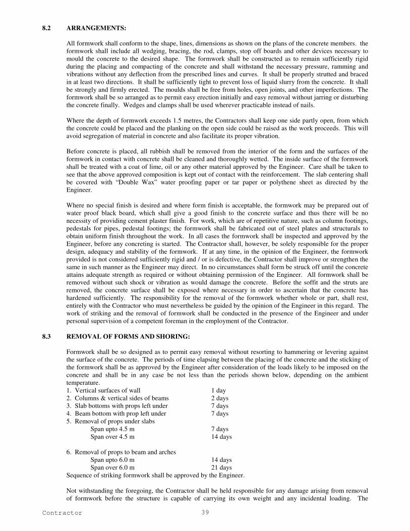
Contractor 39
8.2 ARRANGEMENTS:
All formwork shall conform to the shape, lines, dimensions as shown on the plans of the concrete members. the
formwork shall include all wedging, bracing, the rod, clamps, stop off boards and other devices necessary to
mould the concrete to the desired shape. The formwork shall be constructed as to remain sufficiently rigid
during the placing and compacting of the concrete and shall withstand the necessary pressure, ramming and
vibrations without any deflection from the prescribed lines and curves. It shall be properly strutted and braced
in at least two directions. It shall be sufficiently tight to prevent loss of liquid slurry from the concrete. It shall
be strongly and firmly erected. The moulds shall be free from holes, open joints, and other imperfections. The
formwork shall be so arranged as to permit easy erection initially and easy removal without jarring or disturbing
the concrete finally. Wedges and clamps shall be used wherever practicable instead of nails.
Where the depth of formwork exceeds 1.5 metres, the Contractors shall keep one side partly open, from which
the concrete could be placed and the planking on the open side could be raised as the work proceeds. This will
avoid segregation of material in concrete and also facilitate its proper vibration.
Before concrete is placed, all rubbish shall be removed from the interior of the form and the surfaces of the
formwork in contact with concrete shall be cleaned and thoroughly wetted. The inside surface of the formwork
shall be treated with a coat of lime, oil or any other material approved by the Engineer. Care shall be taken to
see that the above approved composition is kept out of contact with the reinforcement. The slab centering shall
be covered with “Double Wax” water proofing paper or tar paper or polythene sheet as directed by the
Engineer.
Where no special finish is desired and where form finish is acceptable, the formwork may be prepared out of
water proof black board, which shall give a good finish to the concrete surface and thus there will be no
necessity of providing cement plaster finish. For work, which are of repetitive nature, such as column footings,
pedestals for pipes, pedestal footings; the formwork shall be fabricated out of steel plates and structurals to
obtain uniform finish throughout the work. In all cases the formwork shall be inspected and approved by the
Engineer, before any concreting is started. The Contractor shall, however, be solely responsible for the proper
design, adequacy and stability of the formwork. If at any time, in the opinion of the Engineer, the formwork
provided is not considered sufficiently rigid and / or is defective, the Contractor shall improve or strengthen the
same in such manner as the Engineer may direct. In no circumstances shall form be struck off until the concrete
attains adequate strength as required or without obtaining permission of the Engineer. All formwork shall be
removed without such shock or vibration as would damage the concrete. Before the soffit and the struts are
removed, the concrete surface shall be exposed where necessary in order to ascertain that the concrete has
hardened sufficiently. The responsibility for the removal of the formwork whether whole or part, shall rest,
entirely with the Contractor who must nevertheless be guided by the opinion of the Engineer in this regard. The
work of striking and the removal of formwork shall be conducted in the presence of the Engineer and under
personal supervision of a competent foreman in the employment of the Contractor.
8.3 REMOVAL OF FORMS AND SHORING:
Formwork shall be so designed as to permit easy removal without resorting to hammering or levering against
the surface of the concrete. The periods of time elapsing between the placing of the concrete and the sticking of
the formwork shall be as approved by the Engineer after consideration of the loads likely to be imposed on the
concrete and shall be in any case be not less than the periods shown below, depending on the ambient
temperature.
1. Vertical surfaces of wall 1 day
2. Columns & vertical sides of beams 2 days
3. Slab bottoms with props left under 7 days
4. Beam bottom with prop left under 7 days
5. Removal of props under slabs
Span upto 4.5 m 7 days
Span over 4.5 m 14 days
6. Removal of props to beam and arches
Span upto 6.0 m 14 days
Span over 6.0 m 21 days
Sequence of striking formwork shall be approved by the Engineer.
Not withstanding the foregoing, the Contractor shall be held responsible for any damage arising from removal
of formwork before the structure is capable of carrying its own weight and any incidental loading. The

Contractor 40
Contractor shall be wholly responsible for repairing or reconstruction as directed by the Engineer the section of
the works so affected.
1. Shoring and False work Removal:
In retaining wall construction shoring and false work shall not be removed until 21 days after concrete
placement or until concrete has attained at least 90 percent of the 28 days design compressive strength as
demonstrated by control test cylinders, whichever is earlier.
2. Restriction: Construction equipment, or permanent loads shall not be imposed on columns, supported slabs, or supported
beams until concrete has attained the 28 days design compressive strength as demonstrated by control test
cylinders.
3. Concrete Curing during removals:
Concrete shall be thoroughly wetted as soon as forms are first loosened and shall be kept wet during the
removal operations and until curing media or sacking is applied. Portable water supply with hoses or buckets
shall be ready at each removal location before removal operations are commenced.
8.4 SURFACE TREATMENT & FINISH:
When the formwork is struck, all the faces of concrete shall be smooth and sound, free from voids and air holes.
Any roughness or irregularity on the exposed surfaces shall be immediately filled up while the concrete is still
green with cement grout, cement wash and / or 1:1 mortar properly trowelled and finished. Such patching of
the concrete face shall be carried only with the permission of the Engineer. If the concrete is found honey-
combed, the honeycombed portion and whatever surrounding concrete that may be considered unsatisfactory by
the Engineer shall be dismantled and fresh concrete of proper quality shall be provided at Contractor’s cost.
9.0 REINFORCEMENT
9.1 GENERAL:
Reinforcement shall be either plain round mild steel bars Grade I as per IS: 432 (Part - I) or medium tensile
steel bars as per IS: 432 (Part – I) or high strength deformed bars as per IS: 1786. Wire mesh or fabric shall be
in accordance with IS: 1566. Substitution of reinforcement will not be permitted except upon written approval
from the Engineer.
9.2 STORAGE:
The reinforcement shall not be kept in direct contact with the ground but stacked on top of an arrangement of
timber sleepers or the like. If the reinforcing rods have to be stored for a long duration, they shall be coated
with cement wash before stacking and / or be kept under cover or stored as directed by the Engineer. Fabricated
reinforcement shall be carefully stored to prevent damage, distortion, corrosion and deterioration.
9.3 QUALITY:
a. All steel shall be of Grade I quality unless specifically permitted by the Engineer. No re-rolled material will
be accepted. If requested by the Engineer, the Contractor shall submit the manufacturer’s test certificate
for the steel. Random tests on steel supplied by the Contractor may be performed by the Engineer as per
relevant Indian Standards. All costs incidental to such tests shall be at the Contractor’s expense. Steel not
conforming to specifications shall be rejected.
b. All reinforcements shall be clean, free from grease, oil, paint, dirt, loose mill scale, loose rust, dust,
bituminous material or any other substances that will destroy or reduce the bond. All rods shall be
thoroughly cleaned before being fabricated. Pitted and defective rods shall not be used. No welding of
rods to obtain continuity shall be allowed unless approved by the Engineer. If welding is approved, the
work shall be carried out as per IS: 2751 according to the best modern practices and as directed by the
Engineer. In all cases of important connections, tests shall be made to prove that the joints are of full
strength of bars welded. Special precautions, as specified by the Engineer, shall be taken in the welding of
cold worked reinforcing bars and bars other than mid steel.

Contractor 41
9.4 SUBMITAL OF DRAWINGS AND SAMPLES:
Drawings: The Engineer will supply detailed drawings of reinforced concrete works. Working drawings and bar bending
schedules shall be prepared by the Contractor from the drawings supplied to him by the Engineer.
Samples:
At least one month in advance of placing an order by him, the Contractor shall submit four samples of
reinforcing bars which he intends ordering in case, the steel is to be supplied by the Contractor.
The samples shall conform to IS: 10790 Part 2 – 1984. The Engineer may carry out any test he may require to
satisfy that the steel to be brought by the Contractor complies with the test Specifications.
9.5 LAPS AND SPLICES:
Laps and splices for reinforcement shall be as per IS: 456 – 2000. Splices in adjacent bars shall be staggered
and the locations of all splices, except those specified on the approved Drawings, shall be only as approved by
the Engineer. The bars shall not be lapped unless the length required exceeds the maximum available lengths of
bars at site.
9.6 DOWELS:
Where and as designated on the drawings, steel bar dowels shall be provided for anchorage to previously cast
concrete.
For anchorage where shown or required to existing construction, an approved non-shrink epoxy type grout or
approved bolting devices shall be used.
9.7 BENDING:
a. Reinforcement bars supplied bent or in coils, shall be straightened before they are cut to size. Straightening
of bars shall be done cold and without damaging the bars.
b. All bars shall be accurately bent according to the sizes and shapes shown on the approved detailed working
drawings / bar bending schedules. They shall be bent gradually by machine or other approved means.
Reinforcing bars shall not be straightened and in a manner that will injure the material; bars containing
cracks or splits shall be rejected. They shall be bend cold, except bars or over 25mm in diameter which
may be bent hot if specifically approved by the Engineer. Bars, which depend for their strength on cold
working, shall not be bent hot. Bars bent hot shall not be treated beyond cherry red colour (not exceeding
845 degree C) and after bending shall be allowed to cool slowly without quenching. Bars incorrectly bent
shall be used only if the means used for straightening and rebending be such as shall not, in the opinion of
the Engineer, injure the material. No reinforcement shall be bent when in position in the work without
approval, whether or not it is partially embedded in hardened concrete. Bars having kinks or bends other
than those required by design shall not be used.
9.8 FIXING:
Reinforcement shall be accurately fixed by any approved means and maintained in the correct position by the
use of blocks, spacers and chairs, as per IS: 2502, to prevent displacement during placing and compaction of
concrete. Bars intended to be in contact at crossing points shall be securely bound together at all such points
with number 16 gauge annealed soft iron wire. The vertical distances required between successive layers of
bars in beams or similar members shall be maintained by the provision of mild steel spacer bars at such
intervals that the main bars do no perceptibly sag between adjacent spacer bars.
The Contractor shall ensure that all reinforcing bars are thoroughly wire brushed and cleaned free of loose mill
scale, loose rust, coats and paints, oils, mud or other coating.
Mesh reinforcement, where specified shall conform to IS: 1566 – 1982.
Binding wire shall be annealed wire conforming to IS: 280.
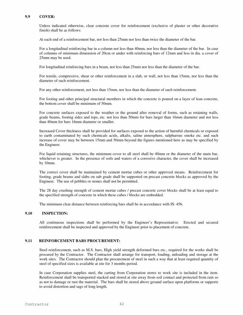
Contractor 42
9.9 COVER:
Unless indicated otherwise, clear concrete cover for reinforcement (exclusive of plaster or other decorative
finish) shall be as follows:
At each end of a reinforcement bar, not less than 25mm nor less than twice the diameter of the bar.
For a longitudinal reinforcing bar in a column not less than 40mm, nor less than the diameter of the bar. In case
of columns of minimum dimension of 20cm or under with reinforcing bars of 12mm and less in dia. a cover of
25mm may be used.
For longitudinal reinforcing bars in a beam, not less than 25mm nor less than the diameter of the bar.
For tensile, compressive, shear or other reinforcement in a slab, or wall, not less than 15mm, nor less than the
diameter of such reinforcement.
For any other reinforcement, not less than 15mm, nor less than the diameter of such reinforcement.
For footing and other principal structural members in which the concrete is poured on a layer of lean concrete,
the bottom cover shall be minimum of 50mm.
For concrete surfaces exposed to the weather or the ground after removal of forms, such as retaining walls,
grade beams, footing sides and tops, etc. not less than 50mm for bars larger than 16mm diameter and not less
than 40mm for bars 16mm diameter or smaller.
Increased Cover thickness shall be provided for surfaces exposed to the action of harmful chemicals or exposed
to earth contaminated by such chemicals acids, alkalis, saline atmosphere, sulphurous smoke etc. and such
increase of cover may be between 15mm and 50mm beyond the figures mentioned here as may be specified by
the Engineer.
For liquid retaining structures, the minimum cover to all steel shall be 40mm or the diameter of the main bar,
whichever is greater. In the presence of soils and waters of a corrosive character, the cover shall be increased
by 10mm.
The correct cover shall be maintained by cement mortar cubes or other approved means. Reinforcement for
footing, grade beams and slabs on sub grade shall be supported on precast concrete blocks as approved by the
Engineer. The use of pebbles or stones shall not be permitted.
The 28 day crushing strength of cement mortar cubes / precast concrete cover blocks shall be at least equal to
the specified strength of concrete in which these cubes / blocks are embedded.
The minimum clear distance between reinforcing bars shall be in accordance with IS: 456.
9.10 INSPECTION:
All continuous inspections shall be performed by the Engineer’s Representative. Erected and secured
reinforcement shall be inspected and approved by the Engineer prior to placement of concrete.
9.11 REINFORCEMENT BARS PROCUREMENT:
Steel reinforcement, such as M.S. bars, High yield strength deformed bars etc., required for the works shall be
procured by the Contractor. The Contractor shall arrange for transport, loading, unloading and storage at the
work sites. The Contractor should plan the procurement of steel in such a way that at least required quantity of
steel of specified sizes is available at site for 3 months period.
In case Corporation supplies steel, the carting from Corporation stores to work site is included in the item.
Reinforcement shall be transported stacked and stored at site away from soil contact and protected from rain so
as not to damage or rust the material. The bars shall be stored above ground surface upon platforms or supports
to avoid distortion and sags of long length.

Contractor 43
The rate quoted for steel reinforcement shall be inclusive of taxes, transport incidental charges etc., apart from
labour component as specified in the respective item in the Bill of Quantities.
Steel brought on site shall be stored in a proper manner as approved by the Engineer so as to avoid distortion,
deterioration and corrosion. The Contractor shall maintain proper registers for the steel account, showing the
steel received at site, steel used, and the balance stock on site, to the entire satisfaction of the Engineer. Further,
it shall be obligatory on the part of the Contractor to submit monthly, quarterly and yearly statements giving the
full account of steel on the works and the balance on hand.
9.12 ANTI CORROSIVE TREATMENT FOR REINFORCEMENT:
9.12.1 The item covers providing fusion bonded epoxy coating not less than 175 microns thickness and upto 300
microns to reinforcement steels bars of all diameters as per IS Code 13620-1993 for RTS rods for RCC works
including testing of coating at plant.
10.0 PLASTERING
10.1 DEFINITIONS:
The term “plastering” shall cover all types of rough or fair finished plastering, rendering, floating and setting
coat or finishing coat, screed, etc., in mud, lime, cement lime or cement mortar.
“Dubbing out” shall mean filling in hollows in the surface of wall and roughly levelling up irregular or out of
plumb surfaces, prior to rendering.
“Rendering” or “rendering coat” shall mean the plaster coat, which is applied following the “Dubbing out” or
the final coat in case of one coat work.
“Floating coat” shall mean the second coat in a three-coat plasterwork, to bring the rendering coat to a true and
even surface before the setting or finishing coat is applied.
“Setting of finishing coat” shall mean final coat in a two or three coat plaster work.
“Thickness of plaster” shall mean the minimum thickness at any point on a surface. This does not include
thickness of dubbing out.
The term “even and fair” as referred to finishing of the plastered surface shall mean a surface finished with a
wooden float.
The term “even and smooth” as referred to finishing of the plastered surface shall mean a surface levelled with
wooden float and subsequently smoothened with a steel trowel.
10.2 SCAFFOLDING:
Where possible, independent scaffolding shall be used to obviate the subsequent restoration of masonry in
putlog and other breaks in the work. Stage scaffolding shall be provided for ceiling plaster.
10.3 PREPARATION OF MORTAR FOR PLASTERING:
10.3.1 Materials:
Cement Mortar:
Cement mortar shall have the proportion of cement to sand as mentioned in the item or in the special provisions
and shall comply with following:
Cement: Cement shall conform to IS: 12269 - 1987 Ordinary Portland Cement shall be used. The weight of ordinary
Portland cement shall be taken as 50 kg. per bag. The Contractor shall ensure that the cement is of sound and
required quality before using it. Any cement, which has deteriorated, caked or which has been damaged shall
not be used. The Specifications covered under the section brickwork and concrete work shall be applicable in
addition.
Water:
Water shall be clean, clear and free from injurious quantities of salt, traces of oil, acids, alkalis, organic matter
and other deleterious materials. The sources of water shall be approved by the Engineer and the containers for
conveyance; storage and handling shall be clean. If necessary, standard cement tests shall be conducted using
the water intended to be used, in comparison with those adding distilled water to check quality of water.
Water shall meet the requirement of 4.3 of IS: 456 – 2000. Generally potable water is fit for mixing and curing.

Contractor 44
Fine Aggregate:
All fine aggregate shall conform to IS: 383 – 1970 and relevant portion of IS: 515 –1959.
Sand shall be clean, well graded, hard, strong, durable and of gritty particles free from injurious amounts of
dust, clay, kankar nodules, soft or flaky particles, shale, alkali, salts, organic matter loam mica or other
deleterious substances and shall be approved by the Engineer. The maximum size of particles shall be limited to
5mm. If the fine aggregate contains more than 4 percent of clay, dust or silt, it shall be washed.
The fine aggregate for cement mortar for masonry and first cost of plaster should generally satisfy the following
grading:
I.S. Sieve Percent by wt. Passing sieve
4.75mm 100
2.36mm 80-95
1.18mm 70-90
600microns 40-85
300microns 5-50
150microns 0-10
The fineness modules shall not exceed 3.00.
The fine aggregate for cement mortar for fine joints of ashlars masonry, pointing and second coat of plaster may
have the following grading:
I.S. Sieve Percent by wt. Passing sieve
4.75mm 100
2.36mm 100
1.18mm 75-100
600microns 40-85
300microns 5-50
150microns 0-10
The fineness modulus shall not exceed 1.6.
IS: 2116 – 1980 shall generally apply for sand for plaster. The fine aggregate should be stacked carefully on a
clean, hard surface so that it will not get mixed up with deleterious foreign materials.
10.3.2 Proportion:
Cement and sand shall be mixed in specified proportions, sand being measured in measuring boxes. The
proportions will be by volume. The mortar may be hand mixed or machine mixed.
10.3.3 Preparation:
In hand mixed mortar, cement and sand in the specified proportions shall be thoroughly mixed dry on a clean
impervious platform. Fresh and clean water as specified above shall be added gradually and thoroughly mixed
to form a stiff plastic mass of uniform colour so that each particle of sand shall be completely covered with a
firm of wet cement.
The water cement ratio may be as under or as directed by the Engineer.
Cement Sand Water – Cement ratio Quantity of water per 50 kg. of
cement (Litres)
1 1 0.25 12.5
1 1 ½ 0.28 14.0
1 2 0.30 15.0
1 2 ½ 0.35 17.5
1 3 0.40 20.0
1 4 0.53 26.5
1 5 0.60 30.0

Contractor 45
1 6 0.70 35.0
1 8 0.90 45.0
Machine mixed mortar shall be prepared in an approved mixer. Water cement ratio shall be as per hand mixed
mortar. The mortar so prepared shall be used within 30 minutes of adding water. The mortar remaining unused
after that period, mortar, which has partially hardened or is otherwise damaged shall not be re tempered or
remixed. It shall be destroyed or thrown away.
10.4 PREPARATION OF BACKGROUND FOR APPLICATION OF PLASTER:
Cleanliness:
All dirt, dust and other foreign matter on masonry and laitance on the concrete surfaces shall be removed by
watering and brushing as required. If the background contains soluble salts particularly sulphates, the
application of plaster shall be done only after the efflorescence of the salts is complete and the efflorescence is
completely removed from the surface.
Joints in brickwork, stone masonry and hollow block, masonry shall be raked out to a depth of not less than
10mm as the work proceeds. Local projection in brickwork and masonry beyond the general wall face shall be
trimmed off where necessary.
Roughness:
Smooth surfaces of in-situ concrete walls and ceilings etc. shall be roughened by wire brushing, if it is not hard;
and by hacking or bush hammering if it is hard, to provide for proper adhesion. Projecting burrs of mortar
because of gaps at joints in shuttering shall be removed. The surface shall be scrubbed clean with wire brushes.
In addition concrete surface shall be pock marked with a pointed tool at spacing of about 50mm, the pocks
made to be not less than 3mm deep.
Suction Adjustments:
Adequate drying intervals shall be allowed between the erection of masonry and plastering to bring the surface
suitable for suction adjustment. High rate of suction makes the plaster weak, porous and friable. The wall shall
not be soaked but only damped evenly before applying the plaster. If the surface becomes dry in spots, such
areas shall be moistened again to restore uniform suction. Excessive water leads to failure of bond between the
plaster and the background.
Evenness:
Any local unevenness must be leveled and projections removed to avoid variance in the thickness of plaster.
Immobility:
Differential movements between the background and the plaster due to moisture change, temperature change,
structural settlement, defection, etc. cause cracks. The major part of such movements shall be allowed to set in
before the plaster is applied.
10.5 PLASTERING:
Plastering Generally:
The type and mix of mortar for plastering, the number of coats to be applied, the surface finish of the plaster
and the background to which the plaster is to be applied shall be as indicated.
The mortar for dubbing out and rendering coat shall be of the same type and mix. Dubbing out may be
executed as a separate coat or along with the rendering coat.
Protection:
All existing work and fittings that are likely to be damaged in the application of plastering shall be protected.
Care shall be taken to avoid, as far as possible, the splashing of mortar on to the finished surfaces such as
joinery, paint work and glazing; all such splashes shall be cleaned off immediately.
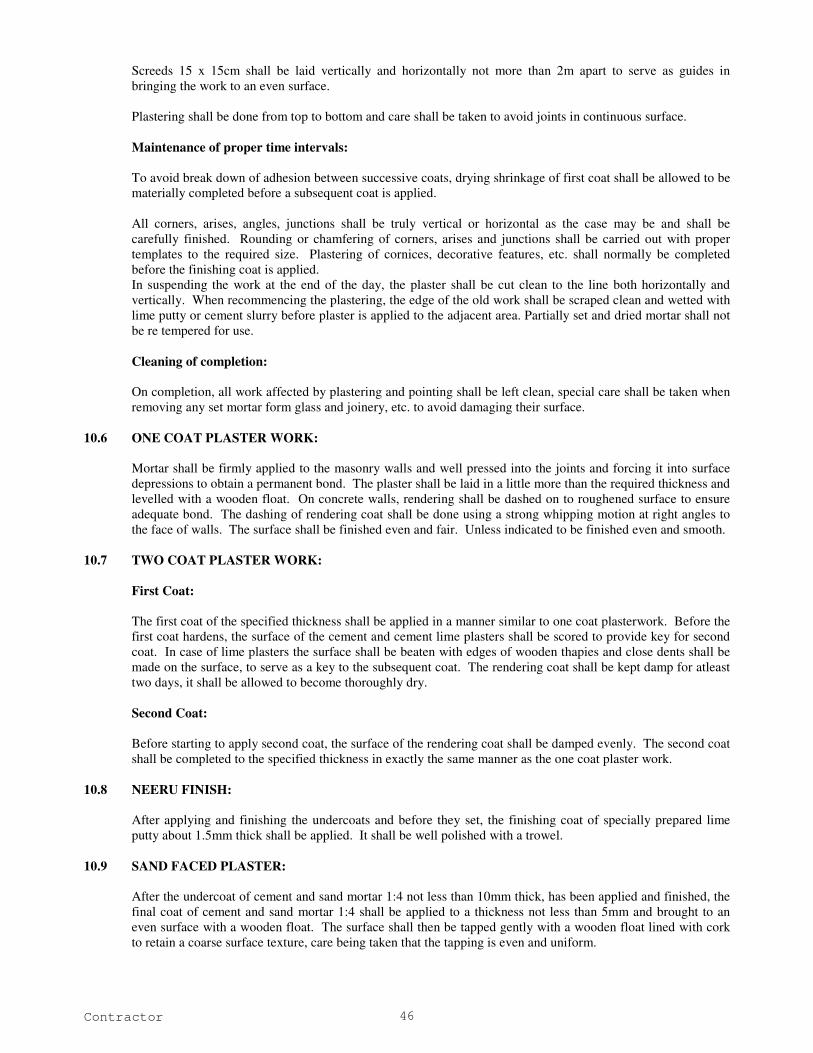
Contractor 46
Screeds 15 x 15cm shall be laid vertically and horizontally not more than 2m apart to serve as guides in
bringing the work to an even surface.
Plastering shall be done from top to bottom and care shall be taken to avoid joints in continuous surface.
Maintenance of proper time intervals:
To avoid break down of adhesion between successive coats, drying shrinkage of first coat shall be allowed to be
materially completed before a subsequent coat is applied.
All corners, arises, angles, junctions shall be truly vertical or horizontal as the case may be and shall be
carefully finished. Rounding or chamfering of corners, arises and junctions shall be carried out with proper
templates to the required size. Plastering of cornices, decorative features, etc. shall normally be completed
before the finishing coat is applied.
In suspending the work at the end of the day, the plaster shall be cut clean to the line both horizontally and
vertically. When recommencing the plastering, the edge of the old work shall be scraped clean and wetted with
lime putty or cement slurry before plaster is applied to the adjacent area. Partially set and dried mortar shall not
be re tempered for use.
Cleaning of completion:
On completion, all work affected by plastering and pointing shall be left clean, special care shall be taken when
removing any set mortar form glass and joinery, etc. to avoid damaging their surface.
10.6 ONE COAT PLASTER WORK:
Mortar shall be firmly applied to the masonry walls and well pressed into the joints and forcing it into surface
depressions to obtain a permanent bond. The plaster shall be laid in a little more than the required thickness and
levelled with a wooden float. On concrete walls, rendering shall be dashed on to roughened surface to ensure
adequate bond. The dashing of rendering coat shall be done using a strong whipping motion at right angles to
the face of walls. The surface shall be finished even and fair. Unless indicated to be finished even and smooth.
10.7 TWO COAT PLASTER WORK:
First Coat:
The first coat of the specified thickness shall be applied in a manner similar to one coat plasterwork. Before the
first coat hardens, the surface of the cement and cement lime plasters shall be scored to provide key for second
coat. In case of lime plasters the surface shall be beaten with edges of wooden thapies and close dents shall be
made on the surface, to serve as a key to the subsequent coat. The rendering coat shall be kept damp for atleast
two days, it shall be allowed to become thoroughly dry.
Second Coat:
Before starting to apply second coat, the surface of the rendering coat shall be damped evenly. The second coat
shall be completed to the specified thickness in exactly the same manner as the one coat plaster work.
10.8 NEERU FINISH:
After applying and finishing the undercoats and before they set, the finishing coat of specially prepared lime
putty about 1.5mm thick shall be applied. It shall be well polished with a trowel.
10.9 SAND FACED PLASTER:
After the undercoat of cement and sand mortar 1:4 not less than 10mm thick, has been applied and finished, the
final coat of cement and sand mortar 1:4 shall be applied to a thickness not less than 5mm and brought to an
even surface with a wooden float. The surface shall then be tapped gently with a wooden float lined with cork
to retain a coarse surface texture, care being taken that the tapping is even and uniform.

Contractor 47
10.10 CURING:
Each coat shall be kept damp continuously for at least two days. Moistening shall commence as soon as the
plaster has hardened sufficiently and is not susceptible to injury. The water shall be applied preferably by using
a fine fog spray. Soaking of wall shall be avoided and only as much water as can be readily absorbed shall be
used. Excessive evaporation on the sunny or wind ward sides of buildings in hot dry weather shall be prevented
by hanging matting or gunny bags on the outside of the plaster and keeping them wet.
After the completion of finishing coat, the plaster shall be kept wet for at least seven days and shall be protected
during that period from extremes of temperature and weather.
10.11 WATER PROOFING PLASTER:
Integral water proofing compound shall be mixed with cement in the proportion indicted by weight. Care shall
be taken to ensure waterproofing material gets well and integrally mixed with cement and does not run out
separately when water is added.

Contractor 48
CHAPTER IV
MS PIPE LINE
General
This part of the specification covers the manufacturing, supply, delivery, lowering, laying, jointing, internal coating,
outer coating, testing and commissioning mild steel pipes.
Applicable standards:
The following specifications, standards and codes are applicable for the fabrication of the pipe stock and fittings. All
standards referred to shall be the latest editions, including all applicable amendments and revisions. Other authoritative
standards that ensure substantial equivalence to the codes listed below will be acceptable.
1. IS 10221 Code of practice for coating and Wrapping of Underground Mild steel pipes
2. IS 4533 – Submerged Arc welding of mild steel and low alloy steels
3. IS 3613 – Acceptance tests for wire flux combinations for submerged arc welding.
4. AWS A 5-17 – Specification for bare mild steel electrodes and fluxes for submerged arc welding.
5. IS 816 – Code of practice for use of metal arc welding for general construction in mild steel.
6. IS 4353 – Submerged arc welding of mild steel and low alloy steels recommendations.
7. IS 817 – Code of practice for training and testing of metal arc welders.
8. IS 1182 – Recommend practice for Radiographic examination of fusion weld Butt joints in steel plant.
9. IS 3658 – Code of practice for liquid penetration flaw detection.
10. ASTM E 94 – Guide for Radio Graphic Testing.
11. ASTM E 165 – Test method for Liquid Penetrant Examination.
12. IS 3600 – Method of testing fusion welded joints and weld metal in steel (Parts 1 to 9)
13. IS 4853 – Recommended practice for Radiographic inspection of fusion welded butt joints in steel pipes.
14. IS 3589 – Seamless or electrically welded steel pipes for water, gas and sewage (168-3 to 2032 outside
diameter)
15. IS 2598 – Safety Code for industrial radiographic practice.
16. IS 2062 – Steel for general structural purposes grade FE 410
17. IS 814, IS 3613, SI 6419 and IS 7280 – Welding consumables – such as electrodes, filler rods and wires.
18. IS 1785, IS 432 – Steel for Reinforcement (Parts I & II)
19. IS 2825 – Code for unfired pressure vessels.
Technical Specification:
The MS pipes shall be of spirally welded, manufactured conforming to IS 5504 -1997 with mild steel HR coils
conforming to IS 10748 grade 3
.
Following tolerances are applicable even if found stringent than the applicable codes
Wall thickness : As per IS 3589
Ovality : As per IS 3589
Straightness : 2 mm per mtr of pipe
Pressure rating:
Pipes shall be suitable for an internal working pressure as per IS 3589.
Length of pipe:
Length of Pipes shall be supplied as per IS 3589.
Pipe Ends:
Pipe ends shall be beveled and end faces shall be at right angle to pipe axis. Beveling shall be done as per standards
suitable for but-welding joints.
Internal lining:
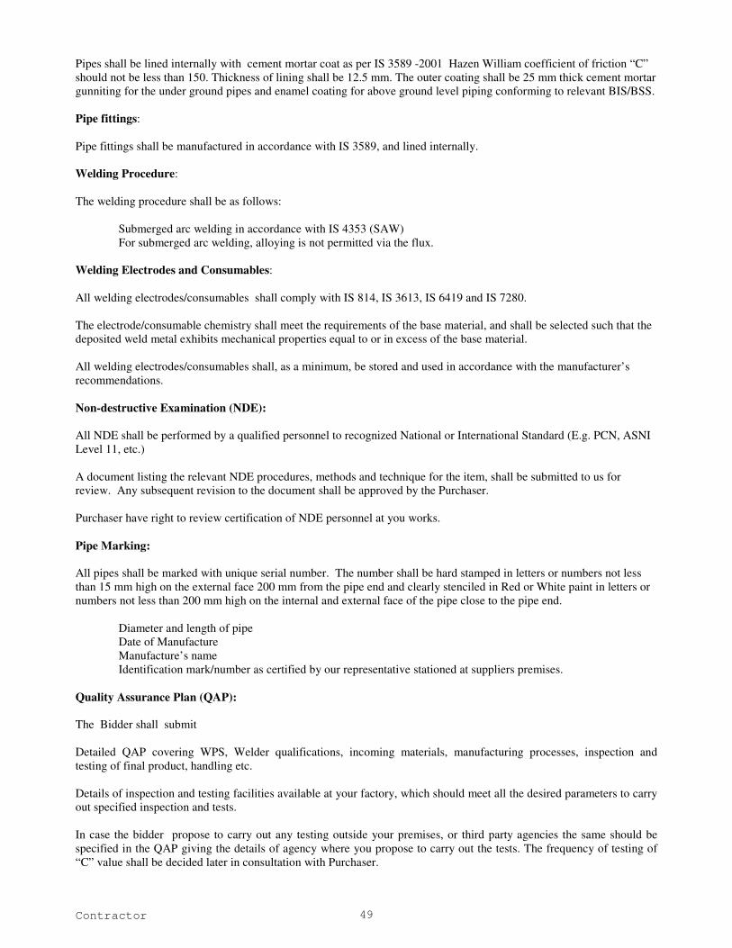
Contractor 49
Pipes shall be lined internally with cement mortar coat as per IS 3589 -2001 Hazen William coefficient of friction “C”
should not be less than 150. Thickness of lining shall be 12.5 mm. The outer coating shall be 25 mm thick cement mortar
gunniting for the under ground pipes and enamel coating for above ground level piping conforming to relevant BIS/BSS.
Pipe fittings:
Pipe fittings shall be manufactured in accordance with IS 3589, and lined internally.
Welding Procedure:
The welding procedure shall be as follows:
Submerged arc welding in accordance with IS 4353 (SAW)
For submerged arc welding, alloying is not permitted via the flux.
Welding Electrodes and Consumables:
All welding electrodes/consumables shall comply with IS 814, IS 3613, IS 6419 and IS 7280.
The electrode/consumable chemistry shall meet the requirements of the base material, and shall be selected such that the
deposited weld metal exhibits mechanical properties equal to or in excess of the base material.
All welding electrodes/consumables shall, as a minimum, be stored and used in accordance with the manufacturer’s
recommendations.
Non-destructive Examination (NDE):
All NDE shall be performed by a qualified personnel to recognized National or International Standard (E.g. PCN, ASNI
Level 11, etc.)
A document listing the relevant NDE procedures, methods and technique for the item, shall be submitted to us for
review. Any subsequent revision to the document shall be approved by the Purchaser.
Purchaser have right to review certification of NDE personnel at you works.
Pipe Marking:
All pipes shall be marked with unique serial number. The number shall be hard stamped in letters or numbers not less
than 15 mm high on the external face 200 mm from the pipe end and clearly stenciled in Red or White paint in letters or
numbers not less than 200 mm high on the internal and external face of the pipe close to the pipe end.
Diameter and length of pipe
Date of Manufacture
Manufacture’s name
Identification mark/number as certified by our representative stationed at suppliers premises.
Quality Assurance Plan (QAP):
The Bidder shall submit
Detailed QAP covering WPS, Welder qualifications, incoming materials, manufacturing processes, inspection and
testing of final product, handling etc.
Details of inspection and testing facilities available at your factory, which should meet all the desired parameters to carry
out specified inspection and tests.
In case the bidder propose to carry out any testing outside your premises, or third party agencies the same should be
specified in the QAP giving the details of agency where you propose to carry out the tests. The frequency of testing of
“C” value shall be decided later in consultation with Purchaser.

Contractor 50
Test Procedures:
Testing of Raw Materials as per applicable standards
Testing of consumables as per applicable standards
Testing of final product such as DP test, radiographic, hydrotest, etc. as per applicable standards.
In Process inspection and testing of final product:
Materials:
Material test reports certifying compliance with relevant standards for each batch/delivery for the following items:
HR coils
Welding consumables
Final Product:
Following testing will be carried out in the presence of Purchasers representative, who will have right to select samples
for testing where 100% testing is not involved.
Hydraulic pressure tests on each pipe as per IS 3589
Dye penetration test on 10% random, selection of weld length of each pipe.
Radiographic examination on 1% random, selection of weld length of each pipe.
The pipes failing in above tests shall be rejected.
In the event of rejections or while inspecting re-worked pipes our representative will have right to demand higher sample
sizes in point (2) and (3) mentioned above.
The cost for all inspection and tests is included in the price.
Record of inspection and testing shall be permanently available with you for any future reference.
Inspection and Testing at site:
Inspection on Delivery:
All pipes together with their associated documentation will be inspected by employer at the point of delivery at site for
transit damages and physical measurements.
In case of rejection, the supplier shall rectify/replace the pipes within 7 (seven) days at his cost.
Inspection and Testing during execution:
The pipeline will be tested for 24 bar working pressure. Any manufacturing defects observed during this pressure test,
should be rectified within 7 days either by repairs or replacement.
The minimum thickness in different sections shall be as given in “Scope of Work” or designed thickness approved by
Engineer In charge, whichever is more. The preferred thickness mentioned in IS: 3589-2001
All the pipes, valves, MS specials and other pipe appurtenances shall be designed to withstand the maximum design
pressures to which it may be subjected to under operation of the project.
Minimum earth cover over pipeline shall be 1.2 m except where the pipeline crosses the CD works above ground.
In case natural ground level is below the pipe bottom, concrete pedestal supports shall be provided. The pipe
thickness shall be designed to withstand
Maximum working pressure plus the surge pressure.
Field test pressure i.e. 1.5 times the working pressures
Collapse pressure
Min. thickness for handling
Contractor 51
Quality Assurance
During the whole process of manufacturing, department's representative shall be present to supervise the Quality
Assurance process and witness the test performed.
Fabrication Of Ms Specials & Fittings
General
Unless and otherwise mentioned in the para below, the dimensions of all MS specials and fittings (bends, tees, scour tee,
reducers, enlargers, etc.) shall in general confirm to the principals of IS: 7322, using MS plate/sheet conforming to
IS:2062. The thickness shall be adequate to sustain field test pressure but shall not be less than the thickness of the pipe
at that point.
The Contractor shall submit the detailed drawing for each special to be used in the pipeline. On approval of the same by
the Engineer-in-Charge, the Contractor will take up the manufacturing. All specials shall be manufactured and coated at
the manufacturer's premises. In exceptional circumstances when welding in trench is unavoidable as advised by the
Engineer-in-Charge, a flanged opening shall be provided for access inside the special for welding. The Contractor has to
ensure the timely manufacturing of the MS specials so that they can be laid in synchronization with the pipe laying. The
joints of adjacent pipe stretches have to be made with gap-pieces approved by the Engineer-in-Charge.
On completion of the manufacturing, the material shall be inspected by the Engineer-in-Charge or his representative at
the manufacturer works. On approval of the latter, the coating and lining for the special will be done by the Contractor as
per the specifications for coatings given in this chapter.
Tolerance for steel fittings shall confirm to the requirements of IS: 7322
Flanged Branches
Flanged branches shall be fabricated in accordance with the general specification and to the Engineer-in-Charge’s
requirement.
Flanged branches for air and scour valves shall be welded into pipe in the required position. The branch for an air valve
shall be vertical and at right angle to the longitudinal axis of pipe. The invert of the branch for a scour valve shall be
horizontal and at right angles to the axis of pipe and shall align with the invert of the barrel of the main pipe.
All the flanges shall be machined to standard thickness, square to the axis of the pipe.
Dimension of the flanges, welding details and welding procedure shall be in accordance with Clause 0.
Bends
Bends to provide change of alignment in pipe laying shall be manufactured to suit the site conditions. Bends of more
than 45º shall not be provided. Bends shall be manufactured from tested pipes by angle cutting of the barrel or by such
other standard procedure and re-welding. Bends shall be lined internally and coated externally as specified for the pipes.
a) Bends shall be fabricated taking into account the vertical and horizontal angles for each case.
b) The bends shall have welded joints and the upstream and downstream ends of each bend shall
have a straight piece of variable lengths as required.
c) Bends shall be designed with deflection angle between two segments as per provisions of IS:
7322 (amended up to date).
d) When the point of intersection of a horizontal angle coincides with that of a vertical angle, or
when these points can be made to coincide, a single combined or compound bend shall be
used.
e) Details of thrust collars anchor bolts, holding down straps, saddle plates should be furnished
together with full specifications in Contractor’s fabrication drawing.
Tapers
Tapers shall be manufactured out of steel plates and lined internally and coated externally. The tapers shall be suitable
for connections to the sluice valves or flanged tailpiece on one side and to MS pipe on the other side. Stiffener rings shall
be provided if required to afford rigidity to pipe. They shall be manufactured generally in accordance with IS: 7322.

Contractor 52
MS flanges
Welding neck flanges confirming to BS 6392 for nominal pressure rating 1.6, 1.0 and 0.6 N/mm2 must be used in
accordance to the design pressure at the place of installations. Nominal Size of flange shall be in conformity to the
equipment or pipe appurtenance with which they are to be used. The flange drilling shall conform to IS 1538 for flanges
upto 1500 mm ID.
Flanges shall be provided at the end of pipes or special where sluice valves, blank flanges, tapers, etc. have to be
introduced. The Contractor shall assemble the flanges in the exact position by marginal cutting, if necessary, so as to get
the desired position of the sluice valves, etc. either vertical or horizontal and shall then fully weld the flanges from both
sides in such a way that no part of the welding protrudes beyond the face of the flanges. In case the welding protrudes
beyond the flanges and if the Engineer-in-Charge orders that such protrusions shall be removed, the Contractor shall file
or chip them off. If required and when ordered by the Engineer-in-Charge, the Contractor shall provide and weld gusset
stiffeners, as directed on site.
Blind Flanges
Blank flanges shall be provided at all ends left unattended for the temporary closure of work and also for commissioning
a section of the pipeline or for testing the pipeline laid. For temporary closures, non-pressure blank flanges consisting of
mild steel plates, tack welded at the pipe ends may be used. For pipes subjected to pressures, the blank flanges or domes
suitably designed as per Engineer-in-Charge’s requirements shall be provided. The thickness of the blank flanges shall
be as defined in IS 6392 for the nominal size and design pressure at the place of installation, the flange drilling for all
flanges upto 1500 mm ID shall conform to the provisions of IS 1538
Stiffener Rings
The Contractor shall provide stiffener rings wherever required as per approved design calculations. The Contractor shall
weld the same to the pipes with one circumferential run on each side.
Straps
In general the use of straps shall not be made. Whenever, it’s uses is unavoidable, approval of Engineer-in-Charge shall
be taken. Wherever pipe laying work is done from two faces and/or has to be done in broken stretches due to any
difficulty met with at site, the final connection has to be made by introducing straps to cover gaps upto 30 cm length.
Straps shall also be provided as per the procedure of fixing expansion joints by the method described. Such straps shall
be fabricated in the field by cutting pipes, slitting them longitudinally and slipping them over the ends to be connected in
the form of a collar. The collar shall be in two halves and shall have its inside diameter equal to the outside diameter of
the pipe to be connected. A minimum lap of 8 cm on either ends of the pipe shall be kept and fillet welds shall be run
both internally and externally for circumferential joint. The longitudinal joints of the collar shall be butt-welded.
All fillet welds shall have a throat thickness of not less than 0.7 times the width of welding.
Manholes
For manhole installation, a fabricated tee with one side flanged must be used. The size of manhole shall not be less than
800 mm and it shall project at least 30 cm above the pipe crown. The 800 mm end must be provided with blind flanges
conforming to clause 0 above.
Closing or Make up sections
Closing or make up sections shall be furnished at appropriate locations on the line to permit field adjustments in pipeline
length to compensate for shrinkage in field welded joints, differences between actual and theoretical lengths and
discrepancies in measurements.
Test Heads
Test heads may be ellipsoidal, standard dished as per ASME code or hemispherical heads. They shall be welded in the
shop and removed after the test. Allowance shall be made in the length of the pipe section receiving the test head for the
welding and removal of the head and preparation of the plate edges for the final weld after testing.
Walkways, Stairs, Ladders, Hand Rails etc.
Walkways, stairs, rungs, ladders, hand rails, etc. wherever necessary shall be provided or as per the directions of
Engineer-in-Charge. These shall conform to well established good engineering practices.

Contractor 53
Dismantling Joint:
All butterfly, scour valves, Bulk water meters or any other online valves etc. shall be installed between flanges with a
flexible MS dismantling joint at one side. The joint must allow dismantling of the valve, meters etc. without causing
stress to the joints of the attached pipes. The minimum clearance of the dismantling joint shall be five (5) cm. The
pressure class of the dismantling joint shall be the same as that of the pipe. Drawings of the dismantling joint shall be
submitted to the Engineer-in-Charge for approval. The Nuts and Bolts of the joint shall be galvanised. The joints shall be
painted/coated as per specification given for exposed pipes.
Inspection and Tests on Pipe and Fittings/Specials
The pipe shall be tested as per provision of Clause in specification.
Each special or fittings shall be subjected to tests as per IS: 7322 before inner and outer coating. The hydraulic test
pressure shall be as per IS: 3589 for specials. Dye penetration test as prescribed in IS:7322 is acceptable in lieu of
hydraulic test for all specials.
The workmanship and marking on pipes must be conforming to clause in specification. All works and material under
specification will be rigidly inspected during all phases of manufacture and testing and such inspection shall not relieve
the Contractor of his responsibility to furnish material and perform work in accordance with these specifications.
The Engineer-in-Charge or the authorized inspection agency shall have free access to those parts of the plants that are
concerned with the furnishing of materials of the performance of work under this specification. The bidder shall furnish
the Engineer-in-Charge reasonable facilities and space without charge for inspection, testing and obtaining of any
information he desires in respect of the quality of material used and the progress and manner of the work.
Sampling of pipes shall be taken as per IS 4711-1974.
Contractor shall provide and operate suitable equipment capable of conducting the specified hydraulic test pressure to the
inside surfaces of the pipe and of sustaining the pressure for the required period.
Laying & Jointing Work Of Mild Steel Pipeline & Fittings/ Specials
Standard
The Laying, jointing and testing of MS pipeline shall confirm to IS: 5822.
General
Unless specified otherwise, the pipeline shall be buried with minimum cover of 1.2 meters at top, as shown on
drawings. No material shall be erected unless it has been previously passed by the Engineer.
Erection of fabricated shells shall be carried out by the Contractor who shall equip himself, at his cost, with all
necessary tools, machinery, labour etc. required for the purpose.
Welding
Except for routine welding of joints, no other work shall be done in the absence of Contractor's engineer, either during
the day time or at night.
Chipping shall not be kept in arrears for more than 15 joints.
Saddle pieces shall be fixed in position after checking bolts holes, by means of templates. These works shall be done
together with the pipe laying work, if pipeline is to be laid above ground in unavoidable circumstances.
Temperature
The components of the pipeline such as base plates, top plates and pedestals have been so designed that the centers of the
plates and pedestals shall coincide at the Mean Temperature (30o).
For this reason, all works such as fixing flanges, base plate etc. in true alignment, and in correct position and track
welding pipes shall be done at the mean temperature.
For ascertaining the temperature, the Contractor shall provide mercury cups and fix them to the pipe shell from outside
and shall also provide thermometers of the required type and range. No extra payment shall be made for this.

Contractor 54
Earth Work
General
The Contractor shall furnish all tools, plant, instruments, qualified supervisory personnel, labour, materials, any
temporary works, consumables, any and everything necessary, whether or not such items are specifically stated herein
for completion of the work in accordance with the Employer’s Requirements.
The Contractor shall survey the site before excavation and set out all lines and establish levels for various works such as
grading, basement, foundations, plinth filling, roads, drains, cable trenches, pipelines etc. Such survey shall be carried
out by taking accurate cross sections of the area perpendicular to established reference/grid lines at 8m intervals or
nearer, if necessary, based on ground profile and thereafter properly recorded.
The excavation shall be carried out to correct lines and levels. This shall also include, where required, proper shoring to
maintain excavations and also the furnishing, erecting and maintaining of substantial barricades around excavated areas
and warning lamps at night.
Excavated material shall be dumped in regular heaps, bunds, riprap with regular slopes within the lead specified and
leveling the same so as to provide natural drainage. Rock/soil excavated shall be stacked properly as approved by the
Engineer in Charge. As a rule, all softer material shall be laid along the center of heaps, the harder and more weather
resisting materials forming the casing on the sides and the top. Rock shall be stacked separately.
Topsoil shall be stock piled separately for later re-use.
Clearing
The area to be excavated/filled shall be cleared of fences, trees, plants, logs, stumps, bush, vegetation, rubbish, slush, etc.
and other objectionable matter. If any roots or stumps of trees are encountered during excavation, they shall also be
removed. The material so removed shall be disposed off as approved by the Engineer in Charge. Where earth-fill is
intended, the area shall be stripped of all loose/ soft patches, top soil containing objectionable matter/ materials before
fill commences.
Excavation
Excavation shall be taken out to such widths, lengths, depths and profiles as are shown on the approved L-section or such
other lines and grades as may be agreed with the Engineer in Charge. Rough excavation shall be carried out to a depth of
150mm above the final level. The balance shall be excavated with special care.
Soft pockets shall be removed below the final level and extra excavation filled up with lean concrete as approved by the
Engineer in Charge. The final excavation should be carried out just prior to laying the blinding course.
To facilitate the permanent works the Contractor may excavate, and also backfill later, outside the lines shown on the
drawings provided by the Contractor as agreed with the Engineer in Charge. Should any excavation be taken below the
specified elevations, the Contractor shall fill it up with concrete of the same class as in the foundation resting thereon,
upto the required elevation at no cost to the Employer.
All excavations shall be to the minimum dimensions required for safety and ease of working. Prior approval of the
Engineer in Charge shall be obtained by the Contractor in each individual case, for the method proposed for the
excavation, including dimensions, side slopes, dewatering, disposal, etc. This approval, shall not in any way relieve the
Contractor of his responsibility for any consequent loss or damage. The excavation must be carried out in the most
expeditious and efficient manner. Side slopes shall be as steep as will stand safely for the actual soil conditions
encountered. Every precaution shall be taken to prevent slips. Should slips occur, the slipped material shall be removed
and the slope dressed to a modified stable slope.
Excavation For Laying pipe along the road
While laying the pipeline below ground along the road side, the contractor shall observe the following:
The contractor shall not be allowed to take earth from the burrow pits if excavation required to take additional earth
results in side slopes steeper than 1:1 in clay dominating soil and 1:1.5 in case of silty sand or sandy soils.
If invert of pipe is kept above the existing burrow pit level or part of pipe is above it, the minimum side slopes of 1:1 in
clay dominating soil and 1:1.5 in case of silty sand or sandy soils shall be provided on the side towards the burrow pit
area so as to provide required cover. The side slopes shall be properly compacted upto 95% of Procter density.
Contractor 55
If earth is taken for providing required cover to pipe from the burrow pits, the burrow pits shall be so graded upto the
nearest drain, that no impounding of water is possible in burrow pit area.
If the pipeline is laid just near the road section, as far as practical minimum cover of 0.9 meter shall be ensured.
Whenever this requirement of cover cannot be ensured, concrete casing of deigned thickness as per considerations given
for design in this chapter shall be provided.
For pipeline to be laid in deep trenches (depth exceeding 3 meters), the pipe shall be laid in trench on pedestals and shall
not be backfilled. The pipeline in this shall will be provided as those specifications that of pipeline to be laid above
ground. The top of the trench shall be covered with Pre-Cast Ferro cement cover of class AA loading. The covers shall
be placed on the masonry walls, build from a suitable level to ensure safety.
Excavation by the Use of Explosives
Unless otherwise stated herein, I.S. Specification “ IS:4081: Safety Code for Blasting and related Drilling Operations”
shall be followed. As far as possible all blasting shall be completed prior to commencement of construction. At all stages
of excavation, precautions shall be taken to preserve the rock below and beyond the lines specified for the excavation, in
the soundest possible condition. The quantity and strength of explosives used, shall be such as will neither damage nor
crack the rock outside the limits of excavation. All precautions, as directed by Engineer in Charge, shall be taken during
the blasting operations and care shall be taken that no damage is caused to adjoining buildings or structures as a result of
blasting operations. In case of damage to permanent or temporary structures, Contractor shall repair the same to the
satisfaction of Engineer in Charge at his cost. As excavation approaches its final lines and levels, the depth of the charge
holes and amount of explosives used shall be progressively and suitably reduced.
The contractor shall obtain a valid Blasting License from the authorities concerned. No explosive shall be brought near
the work in excess of quantity required for a particular amount of firing to be done; and surplus left after filling the holes
shall be removed to the magazine. The magazine shall be built as away as possible from the area to be blasted. Engineer
in Charge’s prior approval shall be taken for the location proposed for the magazine.
In no case shall blasting be allowed closer than 30 metres to any structure or to locations where concrete has just been
placed. In the latter case the concrete must be at least 7 days old.
For blasting operations, the following points shall be observed.
i) Contractor shall employ a competent and experienced supervisor and licensed blaster in-charge of each set of
operation, who shall be held personally responsible to ensure that all safety regulations are carried out.
ii) Before any blasting is carried out, Contractor shall intimate Engineer in Charge and obtain his approval in writing
for resorting to such operations. He shall intimate the hours of firing charges, the nature of explosive to be used
and the precautions taken for ensuring safety.
iii) Contractor shall ensure that all workmen and the personnel at site are excluded from an area within 200 m radius
from the firing point, at least 15 minutes before firing time by sounding warning whistle. The area shall also be
given a warning by sounding a distinguishing whistle.
iv) The blasting of rock near any existing buildings, equipments or any other property shall be done under cover and
Contractor has to make all such necessary muffling arrangements. Covering may preferably be done by MS plates
with adequate dead weight over them. Blasting shall be done with small charges only and where directed by
Engineer in Charge, a trench shall have to be cut by chiseling prior to the blasting operation, separating the area
under blasting from the existing structures.
v) The firing shall be supervised by a Supervisor and not more than 6 (six) holes at a time shall be set off
successively. If the blasts do not tally with the number fired, the misfired holes shall be carefully located after half
an hour and when located, shall be exploded by drilling a fresh hole along the misfired hole (but not nearer than
600 mm from it) and by exploding a new charge.
vi) A wooden tamping rod with a flat end shall be used to push cartridges home and metal rod or hammer shall not be
permitted. The charges shall be placed firmly into place and not rammed or pounded. After a hole is filled to the
required depth, the balance of the hole shall be filled with stemming which may consist of sand or stone dust or
similar inert material.
vii) Contractor shall preferably detonate the explosives electrically.

Contractor 56
viii) The explosives shall be exploded by means of a primer which shall be fired by detonating a fuse instantaneous
detonator (F.I.D) or other approved cables. The detonators with F.I.D. shall be connected by special nippers.
ix) In dry weather and normal dry excavation, ordinary low explosive gunpowder may be used. In damp rock, high
explosive like gelatin with detonator and fuse wire may be used. Underwater or for excavation in rock with
substantial accumulated seepage electric detonation shall be used.
x) Holes for charging explosives shall be drilled with pneumatic drills, the drilling pattern being so planned that rock
pieces after blasting will be suitable for handling without secondary blasting.
xi) When excavation has almost reached the desired level, hand trimming shall have to be done for dressing the
surface to the desired level.
Any rock excavation beyond an over break limit of 75 mm shall be filled up as instructed by Engineer in Charge,
with concrete of strength not less than M10. Stopping in rock excavation shall be done by hand trimming.
xii) Contractor shall be responsible for any accident to workmen, public or Employer’s property due to blasting
operations. Contractor shall also be responsible for strict observance of rules, laid by Inspector of explosives, or
any other Authority duly constituted under the State and / or Union Government as applicable at the place of
excavation.
Stripping Loose Rock
All loose boulders, detached rocks partially and other loose material which might move therewith not directly in the
excavation but so close to the area to be excavated as to be liable, in the opinion of Engineer in Charge, to fall or
otherwise endanger the workmen, equipment, or the work shall be stripped off and removed from the area of the
excavation. The method used shall be such as not to render unstable or unsafe the portion which was originally sound
and safe.
Any material not requiring removal in order to complete the permanent works, but which, in the opinion of Engineer in
Charge, is likely to become loose or unstable later, shall also be promptly and satisfactorily removed.
Timber Shoring
Close timbering shall be done by completely covering the sides of the trenches and pits generally with short, upright
members called 'polling boards'. These shall be of minimum 25 cm x 4 cm sections or as approved by the Engineer in
Charge. The boards shall generally be placed in position vertically side by side without any gap on each side of the
excavation and shall be secured by horizontal walling of strong wood at maximum 1.2 metre spacing, strutted with
ballies or as approved by the Engineer in Charge. The length of the ballie struts shall depend on the width of the trench
or pit. If the soil is very soft and loose, the boards shall be placed horizontally against each side of the excavation and
supported by vertical walling, which in turn shall be suitably strutted. The lowest boards supporting the sides shall be
taken into the ground and no portion of the vertical side of the trench or pit shall remain exposed, so as to render the
earth liable to slip out.
Timber shoring shall be 'close' or 'open' type, depending on the nature of soil and the depth of pit or trench. The type of
timbering shall be as approved by the Engineer in Charge. It shall be the responsibility of the Contractor to take all
necessary steps to prevent the sides of excavations, trenches, pits, etc. from collapsing.
Timber shoring may also be required to keep the sides of excavations vertical to ensure safety of adjoining structures or
to limit the slope of excavations, or due to space restrictions or for other reasons. Such shoring shall be carried out,
except in an emergency, only under instructions from the Engineer in Charge.
The withdrawal of the timber shall be done carefully to prevent the collapse of the pit or trench. It shall be started at one
end and proceeded with, systematically to the other end. Concrete or masonry shall not be damaged during the removal
of the timber.
In the case of open timbering, the entire surface of the side of trench or pit is not required to be covered. The vertical
boards of minimum 25 cm x 4 cm sections shall be spaced sufficiently apart to leave unsupported strips of maximum 50
cm average width. The detailed arrangement, sizes of the timber and the spacing shall be subject to the approval of the
Engineer in Charge. In all other respects, the Employer’s Requirements for close timbering shall apply to open
timbering.
Contractor 57
In case of large pits and open excavations, where shoring is required for securing safety of adjoining structures or for
any other reasons and where the planking across sides of excavations/pits cannot be strutted against, suitable inclined
struts supported on the excavated bed shall be provided. The load from such struts shall be suitably distributed on the bed
to ensure no yielding of the strut.
Dewatering
The Contractor shall ensure that the excavation and the structures are free from water during construction and shall take
all necessary precautions and measures to exclude ground/rain water so as to enable the works to be carried out in
reasonably dry conditions in accordance with the construction programme. Sumps made for dewatering must be kept
clear of the excavations/trenches required for further work. The method of pumping shall be approved by Engineer in
Charge, but in any case, the pumping arrangement shall be such that there shall be no movement of subsoil or blowing in
due to differential head of water during pumping. Pumping arrangements shall be adequate to ensure no delays in
construction. The dewatering shall be continued for at least (7) seven days after the last pour of the concrete. The
Contractor shall, however, ensure that no damage to the structure results on stopping of dewatering.
The Contractor shall study the sub-soil conditions carefully and shall conduct any tests necessary at the site with the
approval of the Engineer in Charge to test the permeability and drainage conditions of the sub-soil for excavation,
concreting etc., below ground level.
The scheme for dewatering and disposal of water shall be approved by the Engineer in Charge. The Contractor shall
suitably divert the water obtained from dewatering from such areas of site where a build up of water in the opinion of the
Engineer in Charge obstructs the progress of the work, leads to insanitary conditions by stagnation, retards the speed of
construction and is detrimental to the safety of men, materials, structures and equipment.
When there is a continuous inflow of water and the quantum of water to be handled is considered in the opinion of
Engineer in Charge, to be large, a well point system- single stage or multistage, shall be adopted. The Contractor shall
submit to the Engineer in Charge, details of his well point system including the stages, the spacing, number and diameter
of well points, headers etc., and the number, capacity and location of pumps for approval.
Rain Water Drainage
Grading in the vicinity of excavation shall be such as to exclude rain/ surface water draining into excavated areas.
Excavation shall be kept clean of rain and such water as the Contractor may be using for his work by suitably pumping
out the same. The scheme for pumping and discharge of such water shall be approved by the Engineer in Charge.
Carting & Handling
Pipes and fittings/specials shall be transported from the factory to the work sites and stacked at places along the
alignment of the pipeline as directed by Engineer-in-Charge. Contractor shall be responsible for the safety of pipes and
fittings/specials in transit, loading/unloading. Every care shall be exercised in handling pipes and fittings/specials to
avoid damage. While unloading, the pipes and fittings/specials shall not be thrown down from the truck on to hard
surfaces. They should be unloaded on timber skids with steadying ropes or by any other means. Padding shall be
provided between coated pipes, fittings/specials and timber skids to avoid damage to the coating. As far as possible pipes
shall be unloaded on one side of the trench only. The pipe shall be checked for any visible damage (such as broken
edges, cracking or spalling of pipe) while unloading and shall be sorted out for reclamation. Any pipe which shows
sufficient damage to preclude it from being used shall be discarded. Dragging of pipes and fittings/specials along
concrete and similar pavement with hard surfaces shall be prohibited.
Handling of pipes and specials
Coated pipes and specials that are to be stored on supports shall bear on the uncoated ends only. If bearing on coating is
employed the supports shall be not less than 20cm (8 inches) wide and so arranged to prevent damage to the coating.
Storage
Storage if required shall be done on firm level and clean ground and wedges shall be provided at the bottom layer to keep
the stack stable. The stack shall be in pyramid shape or the pipes laid lengthwise or crosswise in alternate layers.
Fittings/specials shall be stacked under cover and separated from pipes.
Contractor 58
Bench mark
Permanent bench marks, atleast four in every Kilometer shall be fixed before any work is started by the contractor in any
section. These benchmarks shall be fixed away from the field of work so as not to be disturbed during the execution and
shall be securely fixed in concrete.
Fencing, Watching and Lightening
The posts of the fencing shall be of timber, securely fixed in the ground not more than 2.5 m. apart. They shall not be
less than 10 cm in dia. or not less than 1.25 m above the surface of ground. There shall be two rails, one near the top of
the posts and the other about 0.5 m above the ground and each shall be of 5 cm to 10 cm in dia. and sufficiently long to
run from post to post which they shall be bound with strong ropes. The method, of projecting rails beyond the posts and
tying together where they meet will not be allowed on any account. All along the edges of the excavated trenches, a bund
of earth about one metre high shall be formed where so required by the Engineer-in-Charge for further protection. Proper
provision shall be made for lighting at night and watchman shall be kept to see that this is properly done and maintained.
In addition to the normal lighting arrangements, the contractors shall provide wherever such work is in progress, battery
operated blinking light (6 volts) in the beginning and end of a trench with a view to provide suitable indication to the
vehicular traffic. The contractor shall provide and display special boards printed with fluorescent paints indicating the
progress of the work along the road. The contractor shall be held responsible for payment of all claims for compensation
as a result of accident or injury to any person or property due to improper fencing, inadequate lighting or non-provision
of red flags. The contractors shall at their own cost provide all notice boards before opening of roads as directed by the
Engineer-in-Charge. Arrangements shall be made by the contractors to direct traffic whenever work in through fare is in
progress.
Pipe Laying above ground
Before commencing the work the bidder shall submit the working drawing of every km of pipeline laying as per the
approved L-section of the pipeline for the section concerned. He shall also study the details of the type of saddles/
concrete pedestals to be provided before the actual work of casting is taken in hand.
Before execution the contractor shall submit detailed designs and drawings and all supports such as portal frames,
saddles, ring girders etc for approval of the department.
Pipe laying above ground shall generally start from the fixidity points on either side, the expansion joints being provided
in the last. Fixing points are at all anchor blocks. Where such blocks are not required for long lengths, fixidity shall be
achieved by fixing the pipeline to the special type of R.C.C. or steel saddles/ concrete pedestals as specified above. The
distance between successive fixidity points shall not exceed 300 m.
Anchor blocks shall be constructed before commencing the pipe laying work in any section. The construction of the
blocks shall be carried out in 3 stages in the first stage the lower part upto 150 mm below the invert of the pipeline
including concrete chairs to support it shall be constructed; in the second stage the pipeline on this part of the block shall
be laid; and lastly, the remaining block around and over the pipeline shall be constructed.
The fixidity saddles/ concrete pedestals and ordinary saddles/ concrete pedestals shall be cast-at least 3 weeks before the
pipeline is laid on them. After all saddles/ concrete pedestals between successive fixity points have been cast, a line plan
showing the actual position thereof shall be prepared, after taking levels and measuring distances. In case of any errors
in casting the pedestals, corrections shall be applied. The pipe laying work shall then start from the fixidity points and
shall proceed towards the expansion joints. The method of jointing the pipes and erecting them on previously cast
R.C.C. saddles/ concrete pedestals shall be determined by the Contractor depending upon the type of plant equipment
and personnel available with them.
The pipe strakes shall be assembled in position on the saddles/ concrete pedestals either by the cranes, portable gantries,
shear legs or any other equipment approved by the Engineer-in-Charge. Normally, not more than two pipes shall be
aligned, tacked and kept in position on temporary supports. The Contractor shall not proceed with further work, until the
circumferential joints of these pipes are fully welded. During assembly, the pipeline shall be supported on wooden
sleepers and wedges, with the free end of the pipeline held in position by slings to avoid deflection due to temperature
variations during the day. In general, the assembly of pipe stretches and one run of welding shall be done during the day
time while full welding including the external gouging and sealing runs shall be done after 5 p.m. or so. The Contractor
shall maintain the continuity of the work by adding at least two more pipes on the second day in a similar manner, after
full welding of the previous joints is completed during the night. While this new work is being done, the Contractor
shall proceed with the work of providing permanent supports for the pipeline assembled and welded previously.

Contractor 59
Fixing Expansion Joint
The work of laying pipeline in aboveground, laying starts from the fixity points and proceeds towards the expansion
joints. It shall be continued until the gap between the pipe ends is less than the lengths of the expansion joint plus pipe
strake length.
At mean temperature the exact gap between pipes shall be measured. Free ends of pipes shall be brought in a correct line
and level; lateral movement, if any, shall be corrected. Then the gap between the free ends shall be made equal to the
exact length of the expansion joint by cutting one of the pipe ends. Choice of the end to be cut must be made from the
point of view of bringing the expansion joint to a central position.
At mean temperature this expansion joint shall be inserted inside the gap and both ends shall be tack welded to the pipe
ends, after pulling the expansion joint..
Welding of these two joints of the expansion joints shall be started only after it is ascertained by taking observations that
the expansion joint is functioning properly.
Protection against scouring of foundation:
Providing pitching:
Wherever the pipeline pedestal or portal foundation are located near a nallaha or are across a nallaha, the bidder shall
provide a cut-off wall upto the scour depth all around the footing/ foundation at a distance of 2 times the depth of
foundations below the existing ground level. The portion between the cut-off wall and the foundation shall be filled with
compacted soil and 30cm thick stone pitching shall be done with weight of stone not less than 40kg. The minimum
section of cut-off wall shall be of 0.3m in width and minimum 2m in depth. The cut-off wall shall be of RR masonry in
cement mortar 1:4 laid on 1:3:6 Cement concrete mix minimum 15cm thickness.
Providing longitudinal walls and cross walls:
Wherever pipe is laid on pedestal across a nallaha/drain or in revines with drain flowing across the pipe alignment,
longitudinal check wall or curtain wall shall be provided on both side of the pipe foundations. The cut-off wall on the
upstream side of nallaha/drain shall be taken at least upto 2m depth from the general ground level or upto the scour depth
which ever is more. The downstream side of cut off wall shall be taken 2.5 m in depth. The area between two wall shall
be filled with compacted soil and a gentle slope shall be provided for drainage of water in case of minor drain, but a
flexible apron shall be provided for bigger nallaha. The minimum width of cut off walls shall be 0.3m. The wall shall be
of RR stone masonary in cement mortar 1:4 and the exposed top face shall be provided 25mm cement coping in M-15
grade or grade as per IS 456 concrete. The base course shall be of 1:3:6 mix concrete of minimum 15cm thickness.
Pipe Laying Below Ground With Soil Cover
The earth work shall be carried out as specified here in.
Before excavating the trench the alignment of pipeline and L-section shall be approved by Engineer-in-Charge. The
work of trench excavation should be commensurate with laying and jointing of the pipeline. It should not be dug in
advance for a length greater than 3 days ahead of work of laying and jointing of pipeline unless otherwise directed by the
Engineer-in-Charge. It is proposed to ensure the following:
Safety precautions have to be incorporated in the work process
Hindrances to the public have to be minimized
The trench shall not be allowed to erode
The trench must not be filled with water
The trench must not be refilled before laying of the pipes
The bed for the laying of the pipes has to be prepared according to the L-Section immediately before laying of the pipes.

Contractor 60
Bedding for pipe line
i) Bedding
The MS pipeline shall generally be laid in ordinary sandy soil for which no extra bedding shall be provided. In
such case, while doing the excavation, the bottom of the trench shall be prepared in a manner so as to match the
curvature of the pipe as far as possible subtending an angle of about 120o at the centre of pipe. Wherever the
bottom of the trench is of such a nature (i.e. decomposed rock/ hard soil/ boulder) which is likely in the opinion
of the Engineer-in-Charge to cause damage to the pipe or coating or an unsuitable material is encountered
which cannot support the pipe, the contractor shall excavate the trench to an additional depth below the required
depth and shall refill to required level with suitable material such as loose soil/excavated earth, to be approved
by the Engineer-in-Charge. The bedding thickness shall be not less than 20 cm under the barrel of the pipes.
The complete pipe has to be covered and surrounded by the same material as used for bedding so that a total
cover of 30cm above the barrel can be achieved. The excavated hard/dense soil can be refilled after bedding and
covering of the pipe with the loose soil/ excavated earth.
The bedding shall be compacted with a light hand rammer. Any reduction in thickness due to compaction shall
be made up by adding earth during ramming. For the purpose of the bedding under this item only screened fine
earth of grain size not larger than 2mm shall be used. The bedding material shall be clean, uncoated and free
form clay lumps, injurious amounts of dust, soft particles, organic matter, loam or other deleterious substances.
During the work of providing bedding and laying the pipeline over it, loose material from the sides or edges of
the trench shall be prevented from falling inside the trench, by providing shoring and taking other measures. Also
where necessary, trench shall be kept dry by pumping out seepage water continuously.
ii) Concrete Bedding:
This type of bedding is as per the drawing appended with the tender document and is to be provided at
locations shown in the drawings or as specified by the Engineer. A concrete bedding using M15 grade is to be
adopted. The concrete work related to this specification is detailed in the specifications of concrete and allied
works.
Lowering and Jointing
The pipe shall be lowered into the trenches by removing only one or two struts at a time. It shall be seen that no part of the
shoring is disturbed or damaged and, if necessary, additional temporary struts may be fixed during the lowering operations.
It shall also be necessary to see that the gunite coating of pipe is not damaged in anyway during the lowering and
assembling .After the pipe is lowered into the trench, it shall be laid in correct line and level by using the levelling
instruments, sight rails, theodolite, etc. Care shall be taken to see that the longitudinal joints of two consecutive pipes at
each circumferential joints are staggered by 90°. While assembling the pipes, the ends shall have to be brought close enough
to leave a uniform gap not exceeding 4mm. If necessary, a marginal cut may be taken to ensure a close fit of the pipe faces.
For this purpose, only experienced cutters who can make uniform and straight cuts, shall be permitted to cut the faces of the
pipes. No extra payment shall be made for such marginal cutting. There shall be no lateral displacement between the pipe
faces to be joined. If necessary, spiders from inside and tightening rings from outside shall be used to bring the two ends in
perfect contact and alignment. It may also be necessary to use jacks for this purpose. In no case shall hammering or
longitudinal slitting be permitted. When the pipe is properly assembled and checked for correct line and level, it shall be
firmly supported on wooden beams and wedges and tack welded. Some portion of the trench may be refilled at this stage so
as to prevent the pipeline from losing its alignment. The tack welded circumferential joints shall then be welded fully. Only
experienced welders, who shall be tested from time to time shall be permitted to carry out the welding work.
On completion of the pipe jointing and external protection, the trench and the welding pits shall be cleaned .The welding
pits shall be filled and compacted in 150mm layers with the bedding material.
Backfilling shall be carried out as detailed here under.
Precautions against Floatation
When the pipeline laid underground or above ground in a long narrow cutting gets submerged in water collected in the
trench of cutting it is subjected to an uplift pressure due to buoyancy and is likely to float if completely or partly empty. In
the design of pipelines, provision is to be made to safeguard against floatation providing sufficient overburden or by
providing sufficient dead weight by means of blocks, etc. Pipe shall be provided against floatation by providing anchor

Contractor 61
blocks as indicated in Drawing in volume IV. Factor of safety for calculations for check against floating shall be taken as
1.5.
In the case of works extending over one or more monsoon seasons, however, special care and precautions are necessary
during the progress of work on this account. The Contractor shall close down pipe laying operations well in time for the
monsoon. The work of providing blocks, refilling the earth to the required level, compacting the same, etc. shall always be
done as soon as the pipeline in the cutting has been laid.
The Contractor shall see that the water shall not be allowed to accumulate in open trenches. Where work is in an incomplete
stage, precautionary work, such as blank-flanging in the open ends of the pipeline and filling the pipeline with water etc.
shall be taken up as directed by the Engineer.
Such works shall be to the Contractor's account and no separate payment shall be made for the same. The Contractor's rate
for pipe laying shall be deemed to include such precautionary measures against floatation.
Protection of the pipeline against floatation during the Contract Period shall be the responsibility of the Contractor. Should
any section of the pipeline float due to his negligence, etc. the entire cost of laying it again to the correct line and level shall
be to his account.
Expansion Bellows:
Expansion bellows shall be provided to take care for variation of temperature range from 2.8o C to 45.6
o C for all pipe
lengths laid above ground level and left uncovered. Each expansion bellow must be placed between two anchor blocks
providing fixidity at two ends.
Expansion bellows burrow type shall be used confirming to EJMA / ASME specifications.
Expansion bellows adopted shall accommodate expansion and contraction movement of pipe by suitable displacement.
Expansion bellows shall be provided at appropriate locations as per provision in IS: 5822-1994 and as shown in the
approved L-section. The maximum distance between the expansion bellows shall be limited to 300 metres. These joints
shall be equal to the internal diameter of the pipeline and shall be tested at 1.5 times the designed working pressure.
Maximum movement of 15 cm’s must be possible at each expansion bellow without any damages to pipe.
Whenever the expansion bellows are provided in pipeline alignment, the same shall have a protective MS cover over the
joint portion to avoid damage to pipe by any external blow.
Civil Works
All the civil works associated with the MS pipeline laying & Jointing work e.g. excavation, embankments construction,
construction of thrust/ anchor blocks, butterfly/ Air/ Scour valves chambers, RCC support structures etc. shall be carried
out in accordance with provisions laid down in chapter “Specification of PSCC pipeline Work”. Specification of material
used, workmanship, testing and sampling of materials shall be in accordance to respective provisions laid down in the
chapter on “Specifications for Civil Works” of this Volume II of bid document.
Documentation
MEASUREMENT AND LOGGING:
Contractor shall prepare a special logbook containing all the relevant data of individual pipe and pipe coating including
heat number, diameter, length, wall thickness, defects, pipe number, lot/batch or materials used for each pipe. Sampling
and testing at site test results at manufacturer's plant(s), tests conducted by independent agency, damages, repairs, rejects
and any other information that Engineer-in-Charge considers to be relevant and required for all incoming bare pipes and
Engineer-in-Charge approved outgoing coated pipes as applicable.
Contractor shall submit this information in the form of a report at the agreed intervals.
Testing At Work Site
Field Testing of Joints
Ten percent of the field joints shall be tested radiographically (Samples at random) as per IS: 4853, in case of failure
20% field joints shall be selected. In case of second failure, 100% field joints shall be radiographed.

Contractor 62
Five percent of the field joints shall be tested ultrasonic test as per IS: 4260.
The welding of pipes in the field should comply with IS 816-1965 and electrode used should comply with IS 814-1967.
Welded joints shall be tested in accordance with procedures laid down in IS 3600-1966 and one test specimen shall be
taken from at least one field joint out of 10.
Field Hydraulic Test
After erection at site and after the concrete anchor/ thrust blocks have been constructed. The entire pipeline shall be
subjected to a hydraulic test as follows, to the required test pressure as per Clause 11 of IS: 5822.
When the field test pressure is less than 2/3 the works test pressures the period of test should be at least 24 hours. The
test pressure shall be gradually raised at a rate of 0.1 N/mm2 per minute.
If a drop in pressure occurs, the quantity of water added in order to reestablish the test pressure should be carefully
measured. This should not exceed 0.1 liter/ mm of pipe diameter per km of pipeline per day for each 30 m head of
pressure applied.
The contractor shall provide and maintain all requisite facilities, instruments, for the field testing of the material. All
pipes, specials, valves and civil works shall be replaced by the contractor free of cost if damaged during testing. All
pipes, specials, valves and Civil Works shall be replaced by the contractor free of cost if damaged during testing.
Flushing And Disinfection Of Mains
The pipeline shall be disinfected before commissioning for use. After testing the main, it shall be flushed with water of
sufficient velocity to remove all dirt and other foreign materials. When this process has been completed, disinfection
(using liquid chlorine, sodium or calcium hypochlorite) shall be done as per of IS: 5822.
Fill, Backfilling and Site Grading
Trenches shall be backfilled with approved selected excavated material only after the successful testing of the pipeline.
The tamping around the pipe shall be done by hand or other hand operated mechanical means. The water content of the
soil shall be as near the optimum moisture content as possible. Filling of the trench shall be carried out simultaneously
on both sides of the pipe in such a manner that unequal pressure does not occur. Each layer shall be consolidated by
watering, ramming, care being taken to avoid damage to the pipeline.
Fill, Backfilling
General
All fill material shall be subject to the Engineer in Charge’s approval. If any material is rejected by Engineer in Charge,
the Contractor shall remove the same forthwith from the site. Surplus fill material shall be deposited/disposed off as
directed by Engineer in Charge after the fill work is completed.
No earthfill shall commence until surface water discharges and streams have been properly intercepted or otherwise dealt
with to the approval of the Engineer in Charge.
Material
To the extent available, selected surplus spoil from excavations shall be used as backfill. Backfill material shall be free
from lumps, organic or other foreign material. All lumps of earth shall be broken or removed. Where excavated material
is mostly rock, the boulders shall be broken into pieces not larger than 150 mm size, mixed with properly graded fine
material consisting of murum or earth to fill the voids and the mixture used for filling.
If fill material is required to be imported, the Contractor shall make arrangements to bring such material from outside
borrow pits. The material and source shall be subject to the prior approval of the Engineer in Charge. The approved
borrow pit areas shall be cleared of all bushes, roots of trees, plants, rubbish, etc. Top soil containing foreign material
shall be removed. The materials so removed shall be disposed of as directed by Engineer in Charge. The Contractor shall
provide the necessary access roads to borrow areas and maintain the same if such roads do not exist.

Contractor 63
Back filling
Where backfilling is required to be carried out with local good earth shall be clean, medium grained and free from
impurities. The filled-in-sand shall be kept flooded with water for 24 hours to ensure maximum consolidation. The
surface of the consolidated earth shall be dressed to required level or slope. Construction of floors or other structures on
sand fill/earth fill shall not be started until the Engineer in Charge has inspected and approved the fill.
Refilling of trenches
On completion of the pipe laying operations in any section, for a length of about 100m and while further work is still in
progress, refilling of trenches shall be started by the Contractor with a view of restricting the length of open trenches.
Pipe laying shall closely follow the progress of Trench Excavation and the Contractor shall not permit unreasonably
excessive lengths of trench excavation to remain open while awaiting testing of the pipeline. If the Engineer considers
that the Contractor is not complying with any of the foregoing requirements, he may prohibit further trench excavation
until he is satisfied with the progress of laying and testing of pipes and refilling of trenches. Only soft earth and murrum
of good quality free from stones boulders, roots, vegetation etc., shall be utilized after the lumps are broken for filling in
around the pipes for atleast 30cm all around for pipes. Filling shall be done in layers not exceeding 150mm and
compacted to 70 to 80% of max. dry density percent of the maximum dry density as per part VII of IS:2720. The
excavated material nearest to the trench shall be used first. Care shall be taken during backfilling, not to injure or disturb
the pipes, joints or coating. Filling shall be carried out simultaneously on both sides of the pipes so that unequal pressure
does not occur. Walking or working on the completed pipeline unless the trench has been filled to height of atleast 30cm
over the top of the pipe except as may be necessary for tamping etc., during backfilling work.
The remaining portion of the trench may be filled in with a mixture of hard and soft material free from boulders and
clods of earth larger than 150mm in size if sufficient quantity of good earth and murrum are not available. Filling in shall
be done in layers not exceeding 225mm in thickness accompanied by adequate, ramming etc., so as to be compacted to
70 to 80% of the maximum dry density as per part VII of IS:2720. Water contents of the soil shall be as near the
optimum moisture content as possible. The trench shall be refilled so as to build up to the original ground level, keeping
due allowance for subsequent settlement likely to take place.
To prevent buckling of pipe shell of diameters 1200mm and above, pipes shall be strutted from inside while the work of
refilling is in progress, for which no separate payment shall be made separately.
Strutting shall be done by means of strong spiders having at least 6 arms which shall be sufficiently stiff to resist all
deformation. Spiders shall be provided at a maximum interval of 2m.
The Engineer in Charge shall, at all times, have powers to decide which portion of the excavated materials shall be for
filling and in which portion of the site and in what manner it shall be so used.
If any material remains as surplus it shall be disposed of as directed by the Engineer, which includes loading, unloading,
transporting and spreading as directed within a distance of 15 km. If the Contractor fails to remove the earth from site
within 7 days after the period specified in a written notice, the Engineer may arrange to carry out such work at the
Contractor's risk and cost or may impose such fine for such omission as he may deem fit. Particular care shall be taken to
keep the trench dry during the entire refilling operation.
If suitable material for refilling is not available for excavation the Contractor shall bring earth, murrum of approved
quality as directed by the Engineer.
No mechanical plant other than approved compacting equipment shall run over or operate within the trench until
backfilling has reached its final level or the approval of the Engineer has been obtained.
In case of excavation of trenches in rock, the filling upto a level 30 cm above the top of the pipe shall be done with fine
materials such as earth, murum, etc. The filling up to the level of the centre line of the pipe shall be done by hand
compaction in layers not exceeding 8 cm whereas the filling above the centre line of the pipe shall be done by hand
compaction or approved means in layers not exceeding 15 cm. The filling from a level 30 cm above the top of the pipe
to the top of the trench shall be done by hand or other approved mechanical methods with broken rock filling of size not
exceeding 15 cm mixed with fine material as available to fill up the voids.
Filling of the trenches shall be carried out simultaneously on both sides of the pipe to avoid unequal pressure on the pipe.
Subsidence in filling: Should any subsidence take place either in the filling of the trenches or near about it during the
maintenance period of 12 months from the completion of the Contract Works, the Contractor shall make good the same
at his own cost or the Engineer may without notice to the Contractor, make good the same in any way and with any
material that he may think proper, at the expense of the Contractor. The Engineer may also, if he anticipates occurrence
of any subsidence, employ persons to give him timely notice of the necessity of making good the same, and the expenses

Contractor 64
on this account shall be charged to the Contractor.
General Site Grading
Site grading shall be carried out as approved by the Engineer in Charge. Excavation shall be carried out as specified in
the Employer’s Requirements. Filling and compaction shall be carried out as specified elsewhere.
If no compaction is called for, the fill may be deposited to the full height in one operation and levelled. If the fill has to
be compacted, it shall be placed in layers not exceeding 225 mm and levelled uniformly and compacted as indicated
elsewhere.
To ensure that the fill has been compacted as specified, field and laboratory tests shall be carried out by the Contractor.
Field compaction tests shall be carried out in each layer of filling until the fill to the entire height has been completed.
This shall hold good for embankments as well. The fill will be considered as incomplete if the desired compaction has
not been obtained.
The Contractor shall protect the earth fill from being washed away by rain or damaged in any other way. Should any slip
occur, the Contractor shall remove the affected material and make good the slip.
If so specified, the rock as obtained from excavation may be used for filling and levelling to indicated grades without
further breaking. In such an event, filling shall be done in layers not exceeding 50 cms approximately. After rock filling
to the approximate level, indicated above has been carried out, the void in the rocks shall be filled with finer materials
such as earth, broken stone, etc. and the area flooded so that the finer materials fill up the voids. Care shall be taken to
ensure that the finer fill material does not get washed out. Over the layer so filled, a 100 mm thick mixed layer of broken
material and earth shall be laid and consolidation carried out by a 12 ton roller. No less than twelve passes of the roller
shall be accepted before subsequent similar operations are taken up.
Clearing the Site
All surplus materials, and all tools and temporary structures shall be removed from the site as directed by Engineer-in-
Charge and the construction site left clean to the satisfaction of Engineer-in-Charge.
CROSSING
GENERAL SPECIFICATIONS
While crossing the National Highway, the pipeline shall be installed in R.C.C. box culvert of size not less than 1.8
meters by 1.8 meters or suitable structure as per the approval of NH authorities shall be provided with minimum
openings of 1.8 m x 1.8 m.. The RCC box culvert or any other structure approved by NH authorities shall be designed
for class AA loading for crossing National and State Highway. The box culvert or any other structure approved by NH
authorities shall cover the entire length of the carpeted road and its shoulders.
For crossing other roads, encasing shall be designed for class A loading. For Kuchha (non-tar) road and other roads
providing box culvert is not necessary and in these cases the encasing of pipes may be done.
ROAD, RAILWAY AND IRRIGATION CANAL CROSSINGS :
At road, canal and railway crossings the work shall be performed to the specifications of local authorities or such public
bodies as per the approval of Engineer in Charge(S) of roads, railways and canals to be crossed. The department shall
apply for the required road crossing permissions and the contractor shall pursue the case with the authority for an early
sanction. The railway crossings shall be done and this work shall also be in the scope of the contractor. For maintaining
the continuity of the laying, the contractor shall keep close liaison with the railway authorities for any early execution of
crossing works. In the conduit/box-culvert constructed, the contractor shall lay the pipes and make necessary connections
at the two ends of the pipe.
In case, however the minimum requirements of the governing agencies are less than those set out in the specifications
given herein, then the requirements given in the specifications given for encased line shall be followed.
At locations wherein the open cut methods are permitted, the Contractor shall pass the carrier pipe through the casing
located in the trench after the approval of the engineer-in-charge in writing and care shall be exercised to avoid damage
to pipe coating and wrapping during this operation. The Contractor shall produce a certificate in writing from concerned
authorities for its satisfactory restoration and payment therefore. Wherever the crossing is permitted by open cut, the
contractor shall provide necessary bye-pass arrangements as per the requirement of concerned authority and

Contractor 65
shall complete the job in minimum possible time. No extra payments shall be made for providing the bye-pass.
The contractor shall adopt the methods such as tunnelling or box pushing of culverts if the National Highway
authorities do not permit open road cut, no additional cost shall be paid in such cases.
At all crossings the carrier pipe shall be laid straight without bends so that if necessary the pipe at a later date may be
replaced without damaging the box culvert. The carried pipe shall extend at least 2 meters beyond the end of box
culvert at either end.
At railway crossings the Contractor shall eliminate unnecessary bending of pipe to conform to the contour of ground by
gradually deepening the ditch at such approaches as directed by the engineer-in-charge. Where the installation of the
casing has been made by open cut Contractor shall install suitable temporary bridge work ensuring the safety of the
traffic aids and safeguards for protection of the public safety, or he shall provide suitable diversions as desired by the
engineer-in-charge.
The method of carrying out a cased crossing by boring for various crossings on this pipeline route shall be jointly
inspected by the representative of the Department, NHAI and Contractor for each category of work prior to
commencement of actual work.
Pipeline under railway track and irrigation canal an applicable portion of the right-of-way shall be encased in accordance
with the specification. This item of work shall include, necessary clearing and grading required therefore, trenching to
the depths and widths required, welding of casing and carrier pipes, testing, lowering in, installation of vent assembles,
end seals, insulator and all other fittings that may be required, backfilling, clean up, complete restoration to the original
condition and further strengthening and protective works as may be required. The work shall be carried out in
accordance with the drawings and as directed by the engineer-in-charge. For various operations mentioned above, the
specifications pertaining to these operations shall apply in addition to the specifications given herein.
The Contractor shall be permitted to use William Sons type Neoprene seals in place of concrete end seals for the
crossings. The representative of the Contractor may also be associated to determine the quality of the material and its
delivery schedule from the open market. However, the particular work shall not be delayed on account of non-
availability of Neoprene end seals. In such case, concrete seals may be provided.
SPECIFICATIONS FOR CASTING RCC BOX & PUSHING THROUGH EMBANKMENT
BOX PUSHING technique or any other structure & technique approved by NH authorities shall be adopted for
crossing the Natioanl Highway if open cut is not permitted by the National Highway authorities. In order to avoid
interference to excavation on existing roads intercepted on pipeline alignment, BOX PUSHING technique may also be
adopted for the laying of pipeline through such road crossings intecepted.
The R.C.C. box segments shall be cast using M-25 or grade as per IS 456, in suitable segments as per the approved
design, and pushed across the embankment by hydraulic jacks, of suitable capacities excavating manually the soil under
the FRONT SHIELD of the box.
The thrust bed required for box pushing shall be of required width and of length and thickness as per design approved
and laid along the longitudinal axis of proposed box. The thrust bed is envisaged in reinforced concrete using grade M-
20 or grade as per IS 456 and designed to resist the reaction induced due to jacking force while pushing the box inside
the embankment. The reaction due to jacking force shall mainly be resisted by frictional resistance between thrust bed
and the earth. However, additional keys provided at the bottom of the bed shall be made use of to develop more
resistance due to passive pressure of the earth.
The concrete below the bottom of each pin pocket shall be done first for positioning them. Aligning these pin pockets is
very important aspect while casting the thrust bed in order to avoid any lateral shifting of the box with respect to it's axis.
Therefore, these boxes shall be held in position by welding MS bars between boxes in longitudinal and lateral directions.
While concreting for entire thrust bed is carried out, two recesses shall be left along the entire length of the thrust bed at
top for housing rails. Levelling of these rails shall be done by providing suitable MS packing plates at suitable spacing.
These recesses shall then be filled with screed mortar. Also, 50 mm thick screed shall be laid on top of the thrust bed
and levelled such that the top of rails shall remain 2 mm protruding above top level of the thrust bed. The pin pockets
shall be covered with precast cover slab before screeding. The thrust bed shall be laid in a slope of 1:700 to avoid lifting
of box during pushing.
In order to facilitate jacking and steering, it is envisaged to cast the box in segments of suitable lengths. The first box
shall be provided with FRONT SHIELD and REAR SHIELD. The front shield shall consists of M.S. Plate with suitable
stiffeners. Enchor bars, welded to the plates shall be embedded in the concrete of the box. The front shield shall be 1.0
Contractor 66
M wide on all four faces with 0.50 M width embedded in box concrete. Similarly, rear shield shall be provided at the
rear end of each box. Half the width of rear shield shall be embedded in box concrete with outer face being flush with
outer surface of the box. For the front 0.50 M length of box, the thickness of top and bottom slab and both sides shall be
reduced by 30 MM. so that rear end of the first box and at front end of remaining box pockets, suitably lined with 6 mm
thick M.S. plates shall be provided to house hydraulic jacks for intermediate jacking. Two pockets shall be provided in
the side walls of box, just below top Haunches and two shall be provided in bottom slab of box, next to Hauches.
The box is designed as a normal box but subject to longitudinal thrust while pushing.
8 mm thick M.S. Plates shall be laid over rails placed in thrust bed to form bottom of box along the length. The bottom
surface of these plates shall remain flush with the bottom of the box. These plates shall be anchored in bottom slab
concrete with welded anchor bars. With this arrangement, while pushing the box over the thrust bed, the contact
between steel to steel surface shall reduce friction. Before casting the box, polythene sheets suitably greased shall be
laid on the top of thrust bed & bottom of box to prevent contact between thrust bed and bottom of box and facilitate
pushing with very smooth, frictionless surface between the thrust bed and bottom of the box.
To withstand reactions of jacking force, jacking pins are provided with M.S. bar handle to facilitate the lifting when
required. The overall dimensions of the pins shall ensure smooth insertion and lifting inside pin pockets.
A jacking rig, fabricated from M.S.Plates and structural steel shall be provided to ensure proper alignment of jacking
force. One end of the jacking rig shall have saddles to house hydraulic jack. The clear width inside rig shall be more
than pin pocket to ensure smooth sliding of rig. Spacers fabricated from M.S.Plates shall be used for filling gaps
between hydraulic jack and jacking pin while pushing. These spacers shall be meant to rest against jacking pin at one
end and jack ram at the other end.
After completion of casting of box, pushing operation shall commence with the rigs laid on top of the thrust bed with one
end of the rig resting against face of the rear end of bottom slab of the first box. The hydraulic jacks shall be properly
housed in the rig so that one end of jack shall rest against the end plate of the rig. The other, ram side of the jack shall
rest against face of jacking pin. When the jack shall be operated, the ram shall be pushed against the jacking pin. This
will make the box to move in the direction of thrust away from jacking pin. When the full displacement of ram be
obtained, the jacks shall be closed and spacers shall be inserted between the jacking pin and the jacks. the jacks shall be
operated again and the box shall be pushed in the direction of thrust. When the rig travel to expose next row of pin
pockets, the jacking pin shall be removed and installed in the next row of pin pockets. This process shall be repeated till
the front shield shall cut into the embankment for about 1.0 M.
The excavation at the front end of the box shall be carried out manually within front shield. the muck shall be removed
from the box. When about 0.50 M of excavation shall be done, the jacks shall be operated again so that front shield shall
be pushed for 30 or 40 cms further inside the embankment. Again, the excavation shall be continued till the entire length
of first box is fully pushed inside the embankment. When rear end of the first box shall be very close to the
embankment, the second box shall then be cast and after adequate curing, pushed to lock inside the rear shield of the
first box. Hydraulic jack shall be housed in intermediate jacking pockets and an intermediate jacking station shall be
opened up. The operation of the jacks in the intermediate jacking station shall be similar to that in the initial stage.
However, in this case, the ram shall rest against plate lining in pockets. After opening the intermediate jacking station,
the intermediate jacks shall be operated while the rear end of 2nd box shall be made to anchor against the jacking pin
through the jacks.
In General following sequence shall be adopted in carrying out the job :
After casting thrust bed, polythene sheets suitably greased shall laid on the top of thrust bed as above explained to
prevent contact between thrust bed and bottom of box.
The reinforcement cage required for base slab with reinforcement for side walls shall be placed in position on bed. The
precast blocks or chairs for provision of cover shall be provided under the cage.
The base slab and side walls up to top of bottom haunch would be concreted with M-25 grade or grade as per IS 456
concrete in one operation leaving the top of side wall rough.
The reinforcement cage for side wall shall be laid in proper position. The lap length shall be provided properly. The side
walls shuttering shall be provided by proper checking of alignment & vertically up to bottom of top haunch.
The surface of hardened concrete shall be thoroughly hacked, swept clean, wetted and covered with a layer of neat
cement grout. The neat cement grout shall be applied to the top and this shall be followed by a 10 mm thick layer of
cement mixed the same proportion as that of cement and sand in concrete and concreting shall be resumed immediately

Contractor 67
thereafter. The first batch of concrete shall be rammed against the old work to avoid formation of any stone pockets
particular attention being paid to corners and closed spots and the concreting of side walls shall be carried out up to the
bottom of top haunch.
The reinforcement cage for top slab shall be laid properly on centering and chairs or precast units for providing cover
shall be laid under cage. The centering shall be checked in alignment and props shall be of sufficient strength.
Concreting of top slab shall be carried out in the same manner as per 5 above.
Pushing of the completed segments of the box shall be commenced as per the procedure described in above paras till the
entire length of the box in the embankment is built up.
After completion of jacking, pressure grouting of concrete shall be carried out of fill joint between segments to make
then water tight and the inside face of the joint treated with smooth finishing etc. complete.
Crossing of Irrigation Canals
The crossing of irrigation canals either below the canal bed or above the canal is to be executed as per the approved L-
section, after obtaining necessary permission from the Irrigation Department or as directed by Engineer-in-Charge. The
Contractor has the full responsibility in case of damage to the Canal embankment or lining due to inattention of his staff.
All Costs for the reinstatement of the original status of the Canal shall be borne by the contractor.
If pipe is to be laid below canal bed level the contractor shall provide concrete lining of canal section in a length of at
least 60 m on either side of the crossing after the excavated portions of the canal embankment are properly constructed
with required compaction. The construction of the concrete lining must not result in any hump in the canal and must be
graded to the requirements of the Irrigation department.

Contractor 68
CHAPTER V
MECHANICAL EQUIPMENT
GENERAL
Material
All materials incorporated in the equipment and Work shall be the most suitable for the service conditions and duty
concerned and shall be new and of reputed make/approved quality, free from imperfections and selected for long life and
minimum maintenance. Non-destructive tests, if called for in the Specification, shall be carried out. All submerged
moving parts of the Plants, or shafts and spindles or faces etc. in contact with them shall be of corrosion resistant
materials. All parts in direct contact with various chemicals, shall be completely resistant to corrosion, or abrasion by
these chemicals, and shall maintain their properties without aging due to the passages of time, exposure to light or any
other cause. All materials shall conform to material standards as per BIS or any equivalent standard.
Workmanship
Workmanship and general finish shall be of first class quality and in accordance with best workshop practice. All welds
shall be as per IS, BS, ASME standards. All tolerances and clearances shall be as per good and sound engineering
practices. Should any material be considered not acceptable by the Engineer, it shall be replaced.
Design Features
As far as practicable, all designs shall be as per latest concept and good engineering practices. The equipment as a whole
shall be new, of robust design for a long & reliable operating life. These shall be capable of working 24 hours per day
continuous operation for prolonged period in the climatic and working conditions prevailing at the site and with the
minimum of maintenance. Particular attention shall be given to high temperature and the rating of electrical and
mechanical equipment, cooling systems and the choice of lubricants shall be for the temperatures as specified.
Paints used shall be as per manufacturers standard but suitable for duty as described. The equipment shall be designed to
provide easy access to and replacement of component parts, which are subject to wear, without the need to replace the
whole units. All Parts in contact with Sewage shall have a life from new to replacement or repair of not less than five
years.
Design features shall include the protection of equipment against damage caused by vermin, dirt, dust and dampness and
to reduce risk of fire. Equipment shall operate without undue vibration and noise, reduction measures shall be adopted
such that levels of 75 dB (A) at a distance of 3 meters is not exceeded. Parts shall be designed to withstand the maximum
stresses under the most severe conditions of normal service materials shall have a high resistance to change in their
properties due to the passage of time, exposure to light, temperature and any other cause, which may have a detrimental
effect upon the performance or life of the Plant.
All rotating elements shall be dynamically and statically balanced.
All equipment shall have name plates specifying the makes, model, rating and other pertinent information.
Lubrication
The equipment shall be lubricated by long life lubricants such that working life is not less than 3000 operation hours.
A complete schedule of recommended oils and other lubricants shall be furnished by the Contractor. The number of
different types of lubricants shall be kept to a minimum. The schedule and the name of the supplier of the lubricants shall
be submitted to the Engineer.
Lubricants shall be oil and grease. Contractor shall indicate indigenously available lubricants, with complete
specification.
Where lubricant is grease, preference shall be given to a pressure system, which does not require frequent adjustment or
recharging. Preferably, life lubricated grease packed bearings shall be used.

Contractor 69
Where more than one special grease is required, a grease gun for each special type shall be supplied and permanently
labeled.
Name Plates
Each equipment of the Plant shall have permanently attached to it in a conspicuous position, a name plate and rating
plate. Upon these shall be engraved or stamped, the manufacturer’s name, type and serial number of the equipment,
details of the loading and duty at which the equipment has been designed to operate, and such diagrams as may be
required by the Engineer. All indicating and operating devices shall have securely attached to them or marked upon them
designations as to their functions and proper manner of use.
Painting
At Manufacturer’s Works
The Contractor shall be responsible for the cleaning, preparation for painting, and priming or otherwise protecting, as
specified, all parts of the Plant/Equipment at the place of manufacture prior to packing.
Parts may be cleaned but surface defects may not be filled in before testing at the manufacturer’s works. Parts subject to
hydraulic test shall be tested before any surface treatment. After test, all surfaces shall be thoroughly cleaned and dried
out, if necessary by washing with and approved de-watering fluid prior to surface treatment. Except where the
specification provides to the contrary all painting materials shall be applied in strict accordance with the paint
manufacturer’s instruction.
Steel and cast iron parts shall be sand blasted to near white cleaning before painting. Edges, sharp covers etc. shall be
ground to a curve before sand blasting. A primer coat of a zinc rich epoxy resin based coating with at least 75 microns
dry film thickness is to be provided. In addition the parts are to be provided with adequate number of coats of coal tar
epoxy polyamine coating to a dry film thickness of 175 microns including primer coating.
At Site
Immediately on arrival at the site, all items of Plant shall be examined for damage to the paint coat applied at the
manufacturer’s works, and any damaged portions shall be cleaned down to the bare metal, all rust removed, and the paint
coat made good with similar type of paint.
After erection, such equipment/items which are not finish painted shall be done so and items that have been finish
painted at the manufacturer’s works shall be touched up for any damaged paint work. For finish painting, two coats of
synthetic enamel conforming to IS: 2932 shall be applied. Dry film thickness of each coat shall be at least 25 microns.
The dry paint film thickness shall be measured by Electrometer or other approved instruments. In order to obtain the dry
film thickness specified, the Contractor shall ensure that the coverage rate given by the paint manufacturer will enable
this thickness to be obtained. Strength of adhesion shall be measured with an adhesion tester and this value shall not be
less than 10 kg/cm2. Painted fabricated steel work which is to be stored prior to erection shall be kept clear of the ground
and shall be laid out or stacked in an orderly manner that will ensure that no water or dirt would accumulate on the
surface. Suitable packing shall be laid between the stacked materials. Where cover is provided, it shall be ventilated.
Galvanizing
Wherever galvanizing has been specified, hot dip process shall be used. The galvanised coating shall be of uniform
thickness. Weight of zinc coatings for various applications shall not be at least those indicated below :-
a) Fabricated steel : 460 gms/sq.m
b) Fasteners : 300 gms/sq.m
Galvanizing shall be carried out after all drilling, punching, cutting, bending and welding operations have been carried
out. Burrs shall be removed before galvanizing. Any Site modification of galvanised parts should be covered well by
zinc rich primer and aluminum paint.
Support for Pipe Work & Valves
All necessary supports, saddles, slings, fixing bolts & foundation bolts shall be provided to support the pipe work. Valve
and other equipment mounted in the pipe work shall be supported in independent of the pipes to which they connect.

Contractor 70
All valves to be installed in straight lines shall be installed between the flanges with a dismantling joint or SS expansions
bellow at one side of the valve. The dismantling joint must allow a minimum clearance of 20 mm. The pressure rating of
the dismantling joint/expansion bellow shall be same as that of the valve.
Centrifugal Pumps
General
The pumps shall be designed to operate satisfactorily without detrimental surges, vibration, noise, or dynamic imbalance
over the required head range. The head-capacity curve of the pump shall have a continually rising head characteristic
with decreasing capacity over the whole range of total head. The shut off head of the pump shall be at least 135 % of the
total head. The Pump shall have the maximum efficiency at the specified duty point.
The Contractor shall guarantee that adequate required Net Positive Suction Head (NPSH) is available to ensure that
pumps can operate without cavitation under the worst operating condition. The required NPSH at duty point and
throughout the range shall be at least 1.0 M, and 0.5 M less than the available NPSH respectively at the lowest water in
the sump.
Each pump must be capable of running satisfactorily in parallel with other sets in the system without throttling and by
itself, without cavitation or overload under all operating conditions within the system resistances indicated.
The unit shall be designed to operate safely at the maximum speed attainable in the reverse direction of rotation due to
water returning through the pump at times when the power supply to the motor is interrupted and the discharge valve
fails to close. The first critical speed of the pump set shall be at least 30 % above the operating speed.
Pumps shall run smooth without undue noise and vibration. The velocity of vibration shall be within the 4.5 mm/sec.
Noise level shall be limited to 85 dBA at a distance of 1.86m.
All rotating parts shall be statically and dynamically balanced as per relevant ISO standards
All pumps shall be provided with mechanical seals of working life not less than 20,000 hours of operation.
A stationery coupling guard shall be provided for the coupling conforming to all relevant safety codes and regulations.
Guard shall be designed for easy installation and removal, complete with necessary support, accessories and fasteners.
The pumping unit shall be provided with a common base plate. The base plate shall be of sufficient size and rigidity to
maintain the pump and motor in proper alignment and position.
Pump design shall be as per IS:6595 and pump performance shall be as per IS:5120.
The power rating of the pump motor shall be the larger of following:
(i) 115 % of the power required by the pump at the duty point.
(ii) 105 % of the maximum power required by the pump from zero discharge to run off point total head.
Materials of Construction
Casing : CI IS210 Gr FG 260
Impeller : SS ASTM A743 Gr CF8M
Shaft : ASTM A276 SS 431
Shaft Sleeve : ASTM A 743 CF8M
Casing ring : SS AISI 410
Gland Bronze conforming to IS 318 Gr LTB 2
Gland Packing : Graphited Asbestos
Base Plate : CI/Epoxy Coated MS
Testing:
Material Test Certificate : Casing, Impeller and shaft
Hydrostatic Test : 1.5 times the shut-off head or twice the rated discharge head, whichever is
greater
Performance Test : As per IS:5120 &: at full speed
NPSH Test : “Type” test certificate for the offered model
Mechanical Balancing : As per ISO:1940, Gr. 6.3 or better
Visual Inspection : Pumps shall be offered for visual inspection before shipment. The pump
components shall not be painted before inspection
Contractor 71
Field Tests : Field performance tests required for satisfactory operation
Inspection: Category A
Submersible Pumps
General Requirements
Pump shall be submersible & non-clog type. Pump shall be suitable for wet pit installation and shall be
suitable for working with the minimum liquid level in thee sump. Components of identical pumps
shall be interchangeable.
The pump shall be designed to handle solids up to a size of 10 mm. Constructional
Features
Impeller shall be non-clog type with smooth blunt edges and large water ways so as to allow free passage of
the large size solids. It shall be free from sharp corners and projections likely to catch and hold rags and
stringy materials. The impeller shall be statically and dynamically balanced. The pump shall have
maximum 2 vanes.
Double Mechanical seals shall be provided to protect the motor from ingress of waste water along the shaft.
The preliminary and secondary seals shall be oil-lubricated with tungsten carbide or silicon -carbide faces
and they should be equipped with an electrical monitoring system for seal failure detection.
Motor and pump shall have a common shaft with bearings. The bearing shall be permanently
greased and maintenance free.
Fixed type submersible pump shall be provided with a 90° duck foot bend for fixing to the concrete floor
of the well. The joint between the pump discharge flange and the delivery piping shall be made by merely
lowering the pump into guide system at the access level. It shall be provided with all necessary fixings for
guiding the pumps during lifting/lowering.
Induction Motor for Submersible Pumps
The submersible motor shall conform to IS:9283:1995. It shall be wet type and having its stator winding
submerged in water.
The motor shall be suitable to work with electric supply of voltage 415 V with permissible variation of ±
10 % and that of frequency of 50 Hz with ± 5 % variation and a combined variation of ± 10 %.
Performance and Characteristics
Motors shall be capable of giving rated output without reduction in the expected life span when operated
continuously under 10% combined varying voltage and frequency supply conditions.
Motors shall be suitable for full voltage direct-on-line (DOL) starting.
The starting current of motor shall not exceed 600% of rated full load current for DOL starting, under any circumstances.
Motors shall be capable of starting and accelerating the load with the applicable method of starting, without
exceeding acceptable winding temperatures, when the supply voltage is in the range 85% of the rated motor
voltage to maximum permissible voltage.
Motor shall be designed to withstand 120% of rated speed for two minutes without any mechanical
damage in either direction of rotation.
The motor vibrations shall be within the limits specified in applicable standard unless otherwise specified for the driven equipment.

Contractor 72
Protection against increase in stator winding temperature (150°C) bearing temperature, leakage in stator
housing and terminal box shall be provided. Minimum 3 nos. thermistors in series to be provided to sense the
stator winding temperature. Sensors to be provided to detect leakage of waste water into oil housing is
above 30% concentration.
Submersible Cable
The cable shall be polymer insulated and polymer sheathed, flexible, 3 core type with flat
G.I. armouring conforming to IS:694;1990.The size of the conductor shall be adequate for continuous use
under water and air. In case a joint is required to be made between the lead cable supplied with the motor
and the user's cable connectors, a detailed procedure of cable jointing to make a watertight joint shall be
provided by the manufacturer.
The size of the conductor and the length of cable should be suitably selected so that the voltage drop at
motor terminals does not exceed 2% of the rated voltage.
Earthing of the motor shall be done in accordance with the relevant provisions of IS:3043:1987.
The insulation shall be given tropical and fungicidal treatment for successful operation of the motor in hot,
humid and tropical climate. The tropicalising treatment shall be as per the applicable standard.
The stator winding shall be made from high conductivity annealed copper conductor, polymer insulated winding
wires conforming to IS:9283:1995 for wet type motors
Constructional Features
Type of pump Fixed
Type of Impeller Semi-open
Method of motor cooling By fluid
Supply system fault level 10 Ka ( or sec.)
Motor starting method DOL
Type of duty (Short time duty,S2 60min)
Class of protection IP 68
Class of insulation F with temperature rise restricted to class B
Materials of Construction
Casing (Pump and Motor) C.I. to IS:210 FG 220 1.5 to 2 % Ni
Impeller ASTM A 743 CF 8M
Shaft Stainless steel :970 GR 316 S13
Wear ring SS 410
Guide system Stainless steel S:970 GR 304 S13
Contractor 73
Valves
General
Valves shall be as per internationally recognized standards. Flanges shall be machined on faces and edges to ISO 7005,
IS 6392. Valves shall be flanged type.
For sluice/gate valves, back seating arrangement shall be provided. Valve buried or installed in underground chamber,
where access to a hand wheel would be impractical, shall be operated by means of extension spindle and/or keys.
Valve shall be suitable for frequent operation as well as operation after long periods of idleness in either open or closed
position. The valve stem, thrust washers, screws, nuts and all other components exposed to the Sewage shall be of a
corrosion resistant grade of stainless steel.
Sluice Valves
Please refer Cl. No. 16.8 of Standard Specifications (Civil Works).
The gate face rings shall be securely pegged over the full circumference.
Valves of 450mm and above shall be provided with thrust bearing arrangement for ease of operation. They shall also
have renewable channel and shoe linings. The gap between the shoe and channel shall be limited to 1.5 mm
Alternatively valve of diameter 450 mm and above may be provided with gear arrangement for ease of operation. The
operation gear of all valves shall be such that they can be opened and closed by one man against an unbalanced head 15
% in excess of the maximum specified rating. Valve and any gearing shall be such as to permit manual operation in a
reasonable time and not exceed a required rim pull of 400 N.
All hand wheels shall be arranged to turn in a clockwise direction to close the valve, the direction of rotation for opening
and closing being indicated on the hand wheels.
The valves to be installed with electrical actuators shall have a provision for manual over ride.
Materials of Construction [this supersedes Cl.No.16.8.3 of Standard Specifications (Civil Works)]
Body, Bonnet, wedge : CI conforming to IS:210 Gr. FG 260
Spindle : SS AISI 431
Seat ring, wedge ring : SS ASTM A 296 CF8
Back Seat Bush : Bronze conforming to IS:318 Gr LTB 2
Parameters 1.1 Type : Non-rising Spindle
1.2 Nominal Pressure : PN 1.0
1.3 Size : 250 mm / 300 mm / 400 mm
1.4 Nature of Operation : Horizontal
1.5 Applicable code : IS : 14846
Tests: Acceptance tests as per IS:14846
Inspection: Category A
Reflux Valves
Valve shall possess high speed closing characteristics and be designed for minimum slam conditions while closing.
External counterweights are not acceptable.
Dual plate check valves shall conform to API 594 and API 598. They shall have metal to metal sealing. The spring
action shall optimize the equal closing rates of each plate especially when the friction coefficients are uneven due to one
plate resting upon one another. The plates shall not drag on the seat while opening. The plates shall not vibrate under full
or partial flow condition.

Contractor 74
Materials of construction.
(a) Body : CI conforming to IS 210 Gr FG 220
(b) Plate : SS AISI 316
(c) Spring : SS AISI 316
(d) Seal : SS AISI 304
Parameters
1.1 Type : Dual plate
1.2 Nominal Pressure : PN 1.0
1.3 Size : ------
1.4 Nature of operation : Horizontal
1.5 Closure characteristic : Non slamming
1.6 Applicable Code : API 594
Tests: Acceptance tests as per API 598
Inspection: Category B
Buterfly Valves
Shall be confirming to IS 13095 – 1991
Materials of construction.
(a) Body :]
(b) Disc :]
(c) Endcover : ] CI conforming to IS 210 Gr FG 200 (d) Gland :]
( e) Hand Wheel : ]
Air Valves
Double ball air valves shall be of the kinetic, double orifice type able to release air in small quantities under pressure and
in large quantities under pressure and in large quantities during filling. They have to allow for large inflow of air during
emptying. The type and locations shall be fixed according to the detailed design and after approved by the Engineer in
charge.
The valves shall have a integrated sluice valve. If required, they shall be installed on a flange welded on the MS
pipe/specials. The possible air velocity (Inflow and Outflow) must be at least 20 m/sec.
Material of Construction and Pressure rating:
Body : CI to IS Gr FG 200
Cowl : CI to IS Gr FG 200
Valve seat, Nut : Leaded tin bronze
Spindle : SS AISI 304
Orifice : SS AISI 304
Ball : Seasoned teak wood, covered with neoprene rubber
Ball Seat : Anti stick material such as nitrile rubber or equivalent
Pressure : Suitable for working pressure of 10 kg/cm2 and instantaneous maximum
Pressure of 16 kg/cm2
Valve Actuators
All actuators shall be motorized type and local controls shall be protected by a lockable cover.
Each actuator shall be adequately sized to suit the application and be continuously rated to suit the modulating control
required. The gearbox shall be oil or grease filled, and capable of installation in any position. All operating spindles,
gears and head stocks shall be provided with adequate points for lubrication.
The valve actuator shall be capable of producing not less than 1½ times the required valve torque considering valve
spindle jamming and shall be suitable for at least 5 continuous operation.

Contractor 75
The actuator starters shall be integrally housed with the actuator in robustly constructed and totally enclosed
weatherproof housing. The motor starter shall be capable of starting the motor under the most severe conditions. The
entire electrical system shall be tropicalised.
The starter housing shall be fitted with contacts and terminals for power supply, remote control and remote positional
indication, and shall also be fitted with internal heaters so as to provide protection against damage due to condensation.
Heaters shall be suitable for single phase operation. The heaters shall be switched “ON” when the starters are “OFF” and
shall be switched “OFF” when the starters on “ON”.
Each actuator shall be equipped as follows :
(a) AC electric motor with engage/disengage clutch mechanism of the dry type.
(b) Reduction gear unit (with thrust bearing if required)
(c) Torque switch mechanism
(d) Limit switch mechanism
(e) Geared hand wheel for manual operation of valve after disengaging motor drive.
(f) Valve position indicator – open/closed
(g) Auto-Manual lever with suitable locking arrangement
(h) Valve position transmitter
(i) Reversing contactor starter complete with overload relays of suitable range and adequately rated control fuses
(j) Actuator with integral starter shall have selection between local/remote operation
(k) Local control switch/push buttons
(l) 415 V/240 V AC control transformer
(m) A white lamp for supervision of main supply to be provided locally.
(n) A potential free contact shall be provided to annunciate over-load trip/main supply failure on remote panel
Special Features
(a) Two (2) DC interposing relays for matching the low voltage of remote commands with the control voltage.
(b) The motor shall be specially designed for valve operation, combining low inertia with a high torque and with
linear characteristics.
(c) All motor operators shall be provided with visible local value position indicators mounted on the operator
assembly itself.
(d) The torque switch shall function to stop the motor on closing or opening of the valve, or upon actuation by the
torque when the value disc is restricted in its attempt to open or close. A minimum of two (2) torque switches,
one for closing direction and one for opening direction shall be provided.
(e) The non-adjustable limit switches shall stop the motor and give indication when the disc has attained the fully
open or close position. Provision shall be made for indication of stuck or jammed valve.
(f) All wiring connections from the various switches shall be brought out on to separate terminal box mounted on
the valve, having liberal space for wiring and making connection.
(g) The terminal box shall be suitable for outdoor use and shall be weather-proof and dust tight.
Reversing Contactor starters for valve Actuators
(a) The reversing starters shall comprise forward and reverse contactors, electrically interlocked with each other.
(b) The terminal overload relays provided with the reversing starters shall be three elements, positive acting,
ambient temperature compensated, time lagged thermal overload relay with adjustable settings. The setting
range shall be properly selected in accordance with the rating of the motor.
(c) Thermal overload relays shall be hardest type.
(d) ‘STOP’ push button of the starter and hand reset device shall be separate from each other.
(e) Overload relay reset push button shall be brought out to the front and made easily accessible.
(f) Overload relay shall be provided with at least one ‘NO’ and one ‘NC’ or one changeover contact.
The minimum continuous current rating of the contractor shall be 16 Amps for all actuator valve motors up to 6 kW.
Tests: Functional Tests as per duty requirements
Inspection: Category A

Contractor 76
CHAPTER VI
DUCTILE IRON PIPELINE
Scope
This specification covers the requirements for manufacturing, testing, supplying, jointing and testing at work
site Ductile iron pipes and fittings used for water conveyance. Data sheet A covers the specific requirement for
the project.
Applicable Codes
The manufacturing testing, supplying, jointing and testing at work sites of Ductile Iron pipes and fittings shall
comply with all currently applicable statutes, regulations, standards and codes.
In particular, the following standards, unless specified herein shall be referred. In all cases, the latest revision of
the codes shall be referred to. If requirements of specifications conflict with the requirements of the codes and
standards, this specification shall govern.
Materials
IS: 8329 Specification for Centrifugally Cast (spun) Ductile Iron pressure pipes for water, gas and sewage
specification.
IS: 638 Sheet rubber jointing and rubber insertion jointing.
IS: 1387 General requirements for supply of metallurgical materials. IS: 1500 Methods for Brinell
hardness test for metallic materials.
IS:9523 Ductile Iron fittings for pressure pipes for water, gas and sewage.
IS: 12820 Dimensional requirement., of rubber gaskets for mechanical Joints and push on joints for use
with cast Iron pipes and fittings for carrying water, gas and sewage.
ISO: 4179 Ductile iron pipes for pressure and nonpressure-Centrifugal cement mortar lining - General
requirements.
ISO: 2531 Ductile iron pipes, fitting and accessories for pressure pipe lines.
Code of Practice
IS: 12288 -Code of practice for use & laying of Ductile iron pipes.
Manufacturing
General
DI pipes and DI fittings shall be systematically checked for any manufacturing defects by experienced
supervisors and a very high standard quality shall be maintained.
Owner / Engineer shall at all reasonable times have free access to the place where the pipes and fittings are
manufactured for the purpose of examining and testing the pipes and fittings and for witnessing the test and
manufacturing.

Contractor 77
All tests specified either in this specification or in the relevant Indian Standards shall be performed by the
supplier/contractor at his own cost and in presence of Owner/Engineer if desired. For this, sufficient notice
before, testing of the pipes and fittings shall be given to Owner/Engineer.
If the test is found unsatisfactory, Owner/Engineer may reject any or all pipes and fittings of that lot. The
decision of Owner/Engineer in this matter shall be final and binding of the contractor and not subject to any
arbitration or appeal.
Materials
The general requirements relating to the supply of material shall be as per IS:1387.
The material for DI fittings shall conform to IS:9523.
Dimensions
The internal diameter, thickness and length of barrel, dimensions of pipes and fittings shall be as per the relevant
tables of IS.8329/IS:9523 for different class of pipes and fittings.
The tolerances for pipes and fittings regarding dimensions and deviations from straight line in case of pipes shall
be as per relevant IS codes.
The standard weight of uncoated pipes and fittings and the permissible tolerances shall be per relevant IS codes.
Workmanship and Finish
The pipes and fittings shall be stripped, with all precautions necessary to avoid warping or shrinking defects. The
pipes and fittings shall be free from defects, other than any unavoidable surface imperfections which result from
the method of manufacture and which do not affect the use of the pipes in the opinion of Engineer.
The pipes and fittings shall be such that they could be cut, drilled or machined. The hardness of the external
unmachined surface shall not exceed 230 HBS.
In the case of spigot and socket pipes and fittings for lead joints, the socket shall be without the centering ring.
In the case of flanged pipes the flanges shall be at the right angles to the axis of the pipe and machined on face.
The bolt holes shall be drilled and located symmetrically off the center line. The bolt hole circle shall be eccentric
with the bore and bolt holes equally spaced. The flanges shall be integrally cast with the pipes and fittings and the
two flanges of the pipes shall he correctly aligned.
Testing
Mechanical Tests
Mechanical tests shall be carried out during manufacture of pipes and fittings as specified in relevant IS codes.
The results so obtained shall be considered to represent all the pipes and fittings of different sizes manufactured
during that period and the same shall be submitted to Owner/Engineer. The method for tensile tests and the
minimum tensile strength requirement for pipes and fittings shall be as per relevant IS codes.
Brinell Hardness Test
For checking the Brinell hardness, the test shall be carried out on the test ring or bars cut from the pipes used for
the ring test and tensile test in accordance with IS 1500.
Retests
If any test piece representing a lot fails in the first instance, two additional tests shall be made on test pieces

Contractor 78
selected from two other pipes from the same lot. If both the test results satisfy the specified requirements, the lot
shall be accepted. Should either of these additional test pieces fail to pass the test, the lot shall be liable for
rejection.
Hydrostatic Test
For hydrostatic test at works, the pipes and fittings shall be kept under test pressure as specified in relevant IS
codes for 15 seconds, shall be struck moderately with a 700 g hammer for conformation of satisfactory sound.
They shall withstand the pressure test without showing any leakage sweating, or other defect of any kind. The
hydrostatic test shall be conducted before coating the pipes and fittings.
Coating
Coating shall not be applied to any pipe and fittings unless its surface is clean dry and free from rust.
All DI pipes and DI fittings shall be mortar lined on internal surface as specified in IS: 4179.
Marking
Each pipe and fitting shall have cast stamped or indelibly painted on it with the following appropriate marks:
a) The nominal diameter.
b) Class reference.
c) Mass of pipe.
d) Date of' manufacture and
e) Manufacturer's name, initials or identification mark.
Marking shall be done as per relevant IS Code.
Jointing
General
Jointing of DI pipes and fittings shall be done as per the requirements of specifications and as per the relevant IS
code. After jointing, extraneous material, if any, shall be removed from the inside of the pipe. In case, rubber
sealing rings/gaskets are used for Jointing these shall conform relevant IS codes and shall be of such type as
mentioned in 'Data Sheet- A’.
Spigot And Socket Pipes
The Spigot and socket pipes and DI fittings shall have push on joints as specified in IS code/ as recommended by
manufacturer.
The gaskets/sealant used for push on joints/flanged joints shall be suitable for water conveyance.
In jointing Ductile iron spigot and socket pipes and fittings with tyton flexible joints the contractor shall take into
account the manufacturer's recommendations as to the methods and equipment to be used in assembling the
joints. In particular the Contractor shall ensure that the spigot end of the pipe to be jointed is smooth and has
been properly chamfered, that the rubber ring as per relevant IS code is correctly positioned in line, before the
joint is made. The rubber rings and any recommended lubricant shall be obtained only through the pipe supplier
or as otherwise directed by engineer.
Contractor 79
Flanged Pipes
The gaskets used between flanges of pipes shall be compressed fibre board or natural/synthetic rubber
conforming to IS:638 of thickness between 1.5 to 3 mm suitable for water conveyance and as specified by
manufacturer. The fibre board shall be impregnated with chemically neutral mineral oil and shall have a smooth
and hard surface. Its weight per square metre shall be not less than 112 g/mm thickness.
Each bolt should be tightened a little at a time taking care to tighten diametrically opposite bolts alternatively.
The practice of fully tightening the bolts one after another is highly undesirable. The bolts shall be of mild steel
unless otherwise specified. They shall be coated with coal tar epoxy coating after tightening.
Cleaning of Pipes and Fittings
Contractor shall ascertain that each stretch of pipeline is absolutely clear and without any obstruction by means of
visual examination of the interior of pipeline suitably lighted by projected sunlight or otherwise. The open end of
an incomplete stretch of pipeline shall be securely closed as may be directed by Owner/Engineer to prevent entry
of mud or silt etc.
If as a result of the removal of any obstructions Owner/Engineer considers that damages may have been caused to
the pipeline, he shall be entitled to order the stretch to be tested immedia tely. Should such test prove
unsatisfactory, contractor shall amend the work and carry out such further tests as are required by Owner /
Engineer.
Testing at Work Site
After the pipes and fittings are laid, jointed and the trench partially backfilled except at the joints the stretch of
pipe line as directed by Engineer shall be subjected to pressure test and leakage test. Where any section of the
pipeline is provided with concrete thrust blocks or anchorages, the pressure test shall not be made until at least
five days have elapsed after the concrete was cast. If rapid hardening cement has been used in these blocks or
anchorages, the tests shall not be made until atleast two day, have elapsed.
Each section of' the pipe line shall be slowly filled with water and all air shall be expelled from the pipe by
tapping at points of highest elevation before the test is made plugs inserted after the tests have been completed.
The specified test pressure as per Data Sheet-A, based on the elevation of the lowest point of the line or section
under test and corrected to the elevation of the test gauge, shall be applied by means of a pump connected to the
pipe as directed by Engineer.
The duration of test shall not be less than 5 minutes. The exposed joints shall be carefully examined and all such
joints showing visible leaks shall be recalculated until water tight. Any cracked or defective pipes and fitting in
consequence of this pressure test shall be removed and replaced by sound material by Contractor at no extra cost
to Owner/Engineer and the test shall be repeated to the satisfaction of Owner/ Engineer.
After the satisfactory completion of pressure test, the section of pipe line shall be subjected to leakage test at a
pressure as specified in Data Sheet- A in section 1. The duration of test shall be 8 hours. No pipe installation
shall be accepted until the leakage is less than the number cm3/hr as determined by the formula :
QL �ND
3.3
P
Where,
QL = the allowable leakage in cm3
/hr
N = number of joints in the length of the pipeline.
Contractor 80
D = diameter in mm, and
P = the average test pressure during the leakage test in kg/cm2
Should any test of pipe laid indicate leakage
greater than that specified above, the defective joints shall be repaired by Contractor at no extra cost to
Owner/Engineer until the leakage is within the specified allowance.
Necessary equipments and water used for testing shall be arranged by Contractor at his own cost. Damage during
testing shall be Contractor's responsibility and shall be rectified by him at no extra cost to Owner/Engineer.
Water used for testing shall be removed from the pipe and not released in the excavated trenches.
After the tests mentioned above are completed to the satisfaction of Owner/Engineer, the backfilling of trenches
shall be done as per specifications in layers.
Measurement
All pipes shall be measured according to the work actually done and no allowance will be made for any waste in
cutting to the exact length required. Pipes and fittings shall be described by their internal diameter and length
measured in running metres. The measurement shall be taken along the centre line of pipe excluding fittings
which shall be measured separately. The lengths of pipes shall not include the portion of spigots within the
sockets of fittings and pipes.
The rate for providing, laying and jointing of DI pipes and fittings shall be deemed to include the cost of jointing
material and testing at work site.
Notes
If any damage is caused to the pipeline during the execution of work or while cleaning./testing the pipeline as
specified, Contractor shall he held responsible for the same and shall replace the damaged pipeline and retest the
same at his own cost of the full satisfaction of Engineer.
Water for testing of pipeline shall be arranged by Contractor at his own cost.
House Service connection in Ductile Iron Pipe
A. SPECIFICATIONS FOR CLAMP SADDLE FOR SERVICE CONNECTIONS
General Specifications:
Clamp saddles for service connection from water distribution mains shall be of wrap around design, wide skirt
and wide straps support, which shall reinforce the pipe while providing excellent stability to the saddle.
Clamp Saddles for service connections shall be of fastened strap type with threaded outlet for service connection.
The service connection threading sizes shall be conforming to IS: 554
Clamp saddles shall be suitable for DI pipes of nominal size 3” (NB 80) to 12” (NB 300) with nominal service
connection size from ½” (NB 15), ¾” (NB 20), 1” (NB 25), 1 ¼” (NB 32), 1 ½” (NB 40) and 2”( NB 50).
The straps shall be elastomer coated (insulated) type for firm grip on pipe as well as to protect the coating on the
pipe and to insulate the un-identical metals. The saddles shall be single strap type upto pipe sizes of NB 600 and
service outlet of ½”, ¾” and 1”.
The saddles shall be double strap type for pipe sizes above NB 600 or when the service outlet is 1 ¼”, 1 ½” or
2”. Fasteners shall be of threaded nut-bolt-washer type. Nut-bolts of size ½” (M12) shall be used for saddles of
Contractor 81
size up to 4” (NB 100) and Nut-bolts of size 5/8” (M16) shall be used for saddles of size 6” (NB 150) and above.
The sealing between the saddle and mains shall be obtained by using a profiled elastomer seal matching to the
curvature of the pipe. The seal shall be of elastomer type, suitable for all potable water applications.
The Material of construction of the body, straps, fasteners etc. shall be of a non corrosive material such as
engineering plastic (PE/PP) or stainless steel or a combination of both.
The design of the saddle body should be such that, the service connection outlet metal insert shall project out
towards pipe side and align with the hole drilled on the pipe to ensure positive locking against rocking or
creeping on the pipe, as might be caused by vibration, pressure or excessive external loading.
The clamp saddles shall be suitable for maximum working pressures upto 10 bars.
Material and Design Specifications:
Saddle Body: Non corrosive Engineering Plastic body moulded with Stainless steel threaded metal insert for
tapping outlet. Also, the stirrup metal plate shall be duly embedded in the plastic body, except at the place of nut-
bolt lugs. Threading size and dimensions shall conform to IS: 554. The body shall have retaining cavity housing
for internal and external retention of the elasomeric seal. Sealing shall be achieved by pressure exerted by the
body while fastening the saddle straps & body on the pipe.
Saddle Strap: Saddle straps shall be made of stainless steel 304 grade to prevent corrosion over the long service
life.
Strap Insulation: Elasomeric (rubber) insulation / lining shall be such that none of the Stainless Steel Strap is in
direct contact with the pipe. It shall ensure a firm non slip grip mounting on the pipe to prevent the saddle from
rocking or creeping on the pipe, as might be caused by vibration, pressure or excessive external loading.
Saddle Seal: It shall be virgin rubber SBR Grade 30 / NBR (NSF 61 approved). It shall be of type pressure
activated hydro-mechanical design. It shall be contoured gasket to provide a positive initial seal which increases
with increase in the line pressure. Gasket shall be gridded mat, with tapered ends, with the outlet section having
oring contacting the saddle body multiple o-rings contacting the pipe, preferably with a Stainless steel
reinforcing ring insert moulded to prevent expansion under pressure. Nuts-Bolts- washer: Stainless Steel Type
304, NC rolled thread, Tightening torque for ½” (M12) nut-bolt: 14-15 kg.m and for 5/8” (M 16) nut-bolt: 21-23
kg.m cost of the full satisfaction of Engineer.
B.COMPRESSION FITTINGS:
Compression fittings used for House service connection comply as per ISO 14236
Material of Construction
Compression fittings material shall confirm to ISO14236.Clause -5.
A .Body-Polypropylene
b. Nut / Cap –Polypropylene.
c. Clip Ring-POM (Acetylic resin )
d. Packing bush- Polypropylene
e. “O” ring – NBR
f. Threaded metal inserts –SS 304 with BSP Threads
Pressure testing
The pressure rating of compression fittings as per clause 8 of ISO 14236 which shall be PN16
Dimensions:
The Dimension of compression fittings shall be as per clause 7.1 of ISO 14236

Contractor 82
Effects on Quality of Water
The Compression fittings for intended for conveyance of Potable water for Human consumption to be tested to comply
with BS 6920 specifications in any of the laboratories like DVGW / KIWA / SPGN / WRc –NSF and certificate of
compliance to be produced for the following parameters :
a. Odour & Flavour of Water.
b. Appearance of Water.
c. Growth of Micro Organism
d.Extraction of substances that may be of concern to Public Health (Cyto Toxicity)
e. Extraction of Metals.
For clear identification of the water services, the nuts of the fittings should be coloured blue while the body to be
black. All fittings with threaded ends should be with BSP threads.
C. U PVC BALL VALVES(STOP COCKS)
Ball Valves used for HOUSE Srevice Connections comply to ISO 4422, Part 4.
Material of Construction:
Ball Valve material shall confirm to as per clause 4 of ISO 4422.
a. Body and Handle - UPVC
b .Seals - PTFE
c .O-rings – NBR/EPDM
d. Material of Construction for compression end will as per specifications for compression fittings.
Pressure Rating
The Pressure of the Ball Valve shall be as per ISO 4422 shall be PN 16.
Dimensions:
The Dimensions of the Ball Valve shall be as per Table 3 of ISO 4422.
Effects on Quality of Water
The Ball Valves intended for conveyance of Potable water for Human consumption to be tested to comply with BS
6920 specifications in any of the laboratories like DVGW / KIWA / SPGN / WRc –NSF and certificate of compliance
to be produced for the following parameters :
a. Odour & Flavour of Water.
b. Appearance of Water.
c. Growth of Micro Organism
d.Extraction of substances that may be of concern to Public Health (Cyto Toxicity)
e. Extraction of Metals.
D. MDPE Pipes
1. General
These specifications are for MDPE Blue PE 80 Pipes for House Service Connections of Dia 20 mm to 32 mm OD.
2. Raw Material
Raw material used to Manufacture MDPE Blue Pipes shall be Virgin Natural Resin PE 80 containing those anti –
oxidants, UV Stabilisers & Pigments necessary for Manufacturing of pipes. The Density of Pipes shall be in the Range
0.926 to 0.940 g/cm3 confirming to ISO 4427 Standard. The PE 80 Resin shall have MRS of 8 Mpa.
3. Effects on Water Quality :
The MDPE PE 80 Blue Pipes shall confirm to clause 3.5 of ISO 4427 for conveyance of Water for Human
Consumption. Also the pipes intended for conveyance of Potable water for Human consumption to be tested to comply
with BS 6920 specifications in any of the laboratories like DVGW/KIWA/SPGN/WRc-NSF and certificate of

Contractor 83
compliance to be produced for the following parameters
a. Odour & Flavour of Water
b. Appearance of Water
c. Growth of Micro Organism
d. Extraction of substances that may be of concern to Public Health (Cyto Toxicity)
e. Extraction of Metals
4. Pressure Rating:
The Pressure rating of MDPE Blue PE 80 Pipes shall be confirming to Clause 4.1 of ISO 4427 : 1996.
5. Colour of Pipes:
The Colour of MDPE PE 80 Pipes shall be BLUE confirming to Clause 3.2 of ISO 4427 : 1996.
6. Dimensions:
The pipe dimensions shall be as per latest revisions of Clause 4.1 of ISO 4427 : 1996 and pipes upto diameters 32 mm
shall be supplied in Coils of 300 mtrs. The internal diameter, wall thickness, length and other dimensions of pipes shall
be as per relevant tables of ISO 4427:1996. Each pipe shall be of uniform thickness throughout its length.
The wall thickness of the PE 80 Pipes shall be as per the table given below:
Nominal Dia of MDPE Pipe (mm) PR rating Wall thickness Minimum Wall thickness Maximum
20 PN 16 2.3 2.8
25 PN 12.5 2.3 2.8
32 PN 12.5 3.0 3.5
The dimension tolerances shall be as per ISO 4427 clause 4.1.3
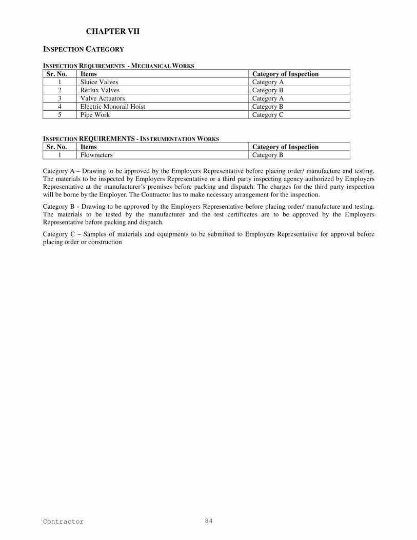
Contractor 84
CHAPTER VII
INSPECTION CATEGORY
INSPECTION REQUIREMENTS - MECHANICAL WORKS
Sr. No. Items Category of Inspection
1 Sluice Valves Category A
2 Reflux Valves Category B
3 Valve Actuators Category A
4 Electric Monorail Hoist Category B
5 Pipe Work Category C
INSPECTION REQUIREMENTS - INSTRUMENTATION WORKS
Sr. No. Items Category of Inspection
1 Flowmeters Category B
Category A – Drawing to be approved by the Employers Representative before placing order/ manufacture and testing.
The materials to be inspected by Employers Representative or a third party inspecting agency authorized by Employers
Representative at the manufacturer’s premises before packing and dispatch. The charges for the third party inspection
will be borne by the Employer. The Contractor has to make necessary arrangement for the inspection.
Category B - Drawing to be approved by the Employers Representative before placing order/ manufacture and testing.
The materials to be tested by the manufacturer and the test certificates are to be approved by the Employers
Representative before packing and dispatch.
Category C – Samples of materials and equipments to be submitted to Employers Representative for approval before
placing order or construction
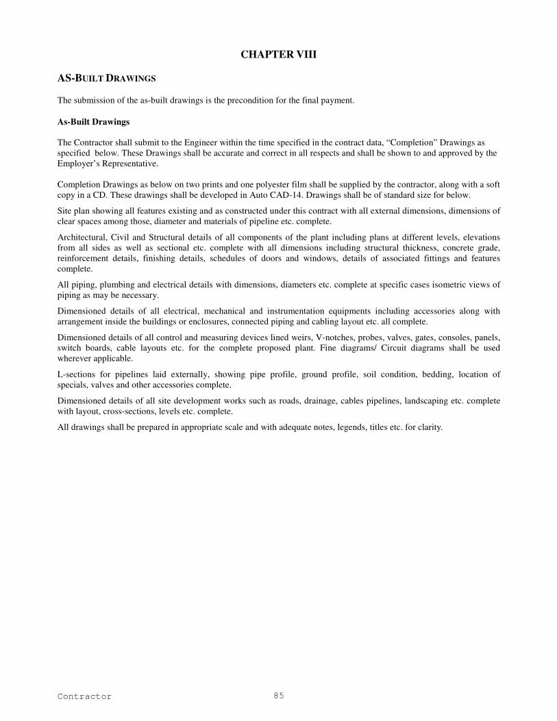
Contractor 85
CHAPTER VIII
AS-BUILT DRAWINGS
The submission of the as-built drawings is the precondition for the final payment.
As-Built Drawings
The Contractor shall submit to the Engineer within the time specified in the contract data, “Completion” Drawings as
specified below. These Drawings shall be accurate and correct in all respects and shall be shown to and approved by the
Employer’s Representative.
Completion Drawings as below on two prints and one polyester film shall be supplied by the contractor, along with a soft
copy in a CD. These drawings shall be developed in Auto CAD-14. Drawings shall be of standard size for below.
Site plan showing all features existing and as constructed under this contract with all external dimensions, dimensions of
clear spaces among those, diameter and materials of pipeline etc. complete.
Architectural, Civil and Structural details of all components of the plant including plans at different levels, elevations
from all sides as well as sectional etc. complete with all dimensions including structural thickness, concrete grade,
reinforcement details, finishing details, schedules of doors and windows, details of associated fittings and features
complete.
All piping, plumbing and electrical details with dimensions, diameters etc. complete at specific cases isometric views of
piping as may be necessary.
Dimensioned details of all electrical, mechanical and instrumentation equipments including accessories along with
arrangement inside the buildings or enclosures, connected piping and cabling layout etc. all complete.
Dimensioned details of all control and measuring devices lined weirs, V-notches, probes, valves, gates, consoles, panels,
switch boards, cable layouts etc. for the complete proposed plant. Fine diagrams/ Circuit diagrams shall be used
wherever applicable.
L-sections for pipelines laid externally, showing pipe profile, ground profile, soil condition, bedding, location of
specials, valves and other accessories complete.
Dimensioned details of all site development works such as roads, drainage, cables pipelines, landscaping etc. complete
with layout, cross-sections, levels etc. complete.
All drawings shall be prepared in appropriate scale and with adequate notes, legends, titles etc. for clarity.

Contractor 86
CHAPTER IX
List of Acceptable Makes or equivalent
S.
No.
Equipments Makes Category
I/II
Short Form
1 Gate Valves Kirloskar Brothers Ltd
Indian Valve Company
Upathyaya Valves Manufacturers P Ltd
Jash
I
I
II
KBL
IVC
UVML
2 Non-return Valves Kirloskar Brothers Ltd
Indian Valve Company
Upathyaya Valves Manufacturers P Ltd
Shiv Durga Iron Works P Ltd
Intervalve
Crane Process
I
I
II
II
KBL
IVC
UVML
SIWL
3 Nuts & Bolts GKW
TATA
GKW
TATA
4 Optic Fibre Cables Delink
Cords
R R Cale
Icon
Aksh
DELINK
CORDS
RR
ICON
AKSH
5 Flow Meters Krone Marshall
ABB
Schlumburger
Endress Hauser
YBL Yokogawa
Magnetrol
KM
ABB
SB
EH
YBL
6 Butterfly valves Kirloskar Brothers Ltd
Fouress
Audco
Tyco
Indian Valve Co.
KBL
Fouress
AIL
TYCO
IVC
7
Sluice valves and Air
valves
Kirloskar Brothers Ltd
Fouress
Audco
Tyco
Indian Valve Co.
KBL
Fouress
AIL
TYCO
IVC 8 Actuator Marsh
L&T
Rotork
MARSH
L&T
ROTORK
Note: The aforementioned list is only an indicative and not an exhaustive list of manufacturers. This list shall be used
only for reference purposes and does not bind the Owner into necessarily approving the listed manufacturer /
vendor / dealer in this list for supply and other installation related activities.
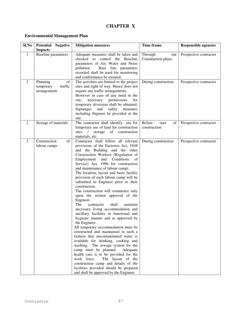
Contractor 87
CHAPTER X
Environmental Management Plan
Sl.No Potential Negative
Impacts
Mitigation measures Time frame Responsible agencies
1 Baseline parameters Adequate measures shall be taken and
checked to control the Baseline
parameters of Air, Water and Noise
pollution. Base line parameters
recorded shall be used for monitoring
and conformance be ensured.
Through out
Construction phase
Prospective contractor
2 Planning of
temporary traffic
arrangements
The activities are limited to the project
sites and right of way. Hence does not
require any traffic arrangements.
However in case of any need in the
site, necessary permissions for
temporary diversion shall be obtained.
Signanges and safety measures
including flagmen be provided at the
site.
During construction Prospective contractor
2 Storage of materials The contractor shall identify site for
temporary use of land for construction
sites / storage of construction
materials, etc.
Before start of
construction
Prospective contractor
3 Construction of
labour camps
Contractor shall follow all relevant
provisions of the Factories Act, 1948
and the Building and the other
Construction Workers (Regulation of
Employment and Conditions of
Service) Act, 1996 for construction
and maintenance of labour camp).
The location, layout and basic facility
provision of each labour camp will be
submitted to Engineer prior to their
construction.
The construction will commence only
upon the written approval of the
Engineer.
The contractor shall maintain
necessary living accommodation and
ancillary facilities in functional and
hygienic manner and as approved by
the Engineer.
All temporary accommodation must be
constructed and maintained in such a
fashion that uncontaminated water is
available for drinking, cooking and
washing. The sewage system for the
camp must be planned. Adequate
health care is to be provided for the
work force. The layout of the
construction camp and details of the
facilities provided should be prepared
and shall be approved by the Engineer
During construction Prospective contractor
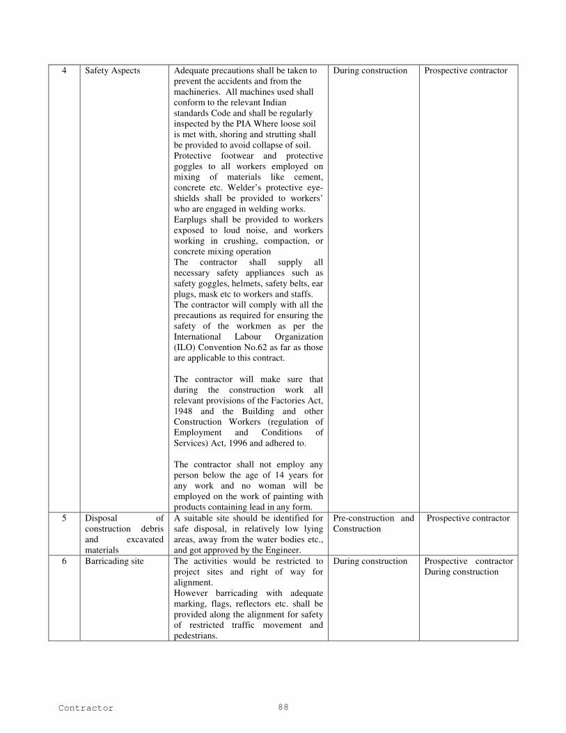
Contractor 88
4 Safety Aspects Adequate precautions shall be taken to
prevent the accidents and from the
machineries. All machines used shall
conform to the relevant Indian
standards Code and shall be regularly
inspected by the PIA Where loose soil
is met with, shoring and strutting shall
be provided to avoid collapse of soil.
Protective footwear and protective
goggles to all workers employed on
mixing of materials like cement,
concrete etc. Welder’s protective eye-
shields shall be provided to workers’
who are engaged in welding works.
Earplugs shall be provided to workers
exposed to loud noise, and workers
working in crushing, compaction, or
concrete mixing operation
The contractor shall supply all
necessary safety appliances such as
safety goggles, helmets, safety belts, ear
plugs, mask etc to workers and staffs.
The contractor will comply with all the
precautions as required for ensuring the
safety of the workmen as per the
International Labour Organization
(ILO) Convention No.62 as far as those
are applicable to this contract.
The contractor will make sure that
during the construction work all
relevant provisions of the Factories Act,
1948 and the Building and other
Construction Workers (regulation of
Employment and Conditions of
Services) Act, 1996 and adhered to.
The contractor shall not employ any
person below the age of 14 years for
any work and no woman will be
employed on the work of painting with
products containing lead in any form.
During construction Prospective contractor
5 Disposal of
construction debris
and excavated
materials
A suitable site should be identified for
safe disposal, in relatively low lying
areas, away from the water bodies etc.,
and got approved by the Engineer.
Pre-construction and
Construction
Prospective contractor
6 Barricading site The activities would be restricted to
project sites and right of way for
alignment.
However barricading with adequate
marking, flags, reflectors etc. shall be
provided along the alignment for safety
of restricted traffic movement and
pedestrians.
During construction Prospective contractor
During construction
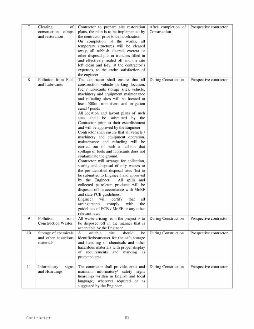
Contractor 89
7 Clearing of
construction camps
and restoration
Contractor to prepare site restoration
plans, the plan is to be implemented by
the contractor prior to demobilization
On completion of the works, all
temporary structures will be cleared
away, all rubbish cleared, excreta or
other disposal pits or trenches filled in
and effectively sealed off and the site
left clean and tidy, at the contractor’s
expenses, to the entire satisfaction of
the engineer.
After completion of
Construction
Prospective contractor
8 Pollution from Fuel
and Lubricants
The contractor shall ensure that all
construction vehicle parking location,
fuel / lubricants storage sites, vehicle,
machinery and equipment maintenance
and refueling sites will be located at
least 500m from rivers and irrigation
canal / ponds
All location and layout plans of such
sites shall be submitted by the
Contractor prior to their establishment
and will be approved by the Engineer
Contractor shall ensure that all vehicle /
machinery and equipment operation,
maintenance and refueling will be
carried out in such a fashion that
spillage of fuels and lubricants does not
contaminate the ground.
Contractor will arrange for collection,
storing and disposal of oily wastes to
the pre-identified disposal sites (list to
be submitted to Engineer) and approved
by the Engineer. All spills and
collected petroleum products will be
disposed off in accordance with MoEF
and state PCB guidelines.
Engineer will certify that all
arrangements comply with the
guidelines of PCB / MoEF or any other
relevant laws
During Construction Prospective contractor
9 Pollution from
Construction Wastes
All waste arising from the project is to
be disposed off in the manner that is
acceptable by the Engineer
During Construction Prospective contractor
10 Storage of chemicals
and other hazardous
materials
A suitable site should be
identified/construct for the safe storage
and handling of chemicals and other
hazardous materials with proper display
of requirements and marking as
protected area.
During Construction Prospective contractor
11 Informatory signs
and Hoardings
The contractor shall provide, erect and
maintain informatory/ safety signs
hoardings written in English and local
language, wherever required or as
suggested by the Engineer
During Construction Prospective contractor
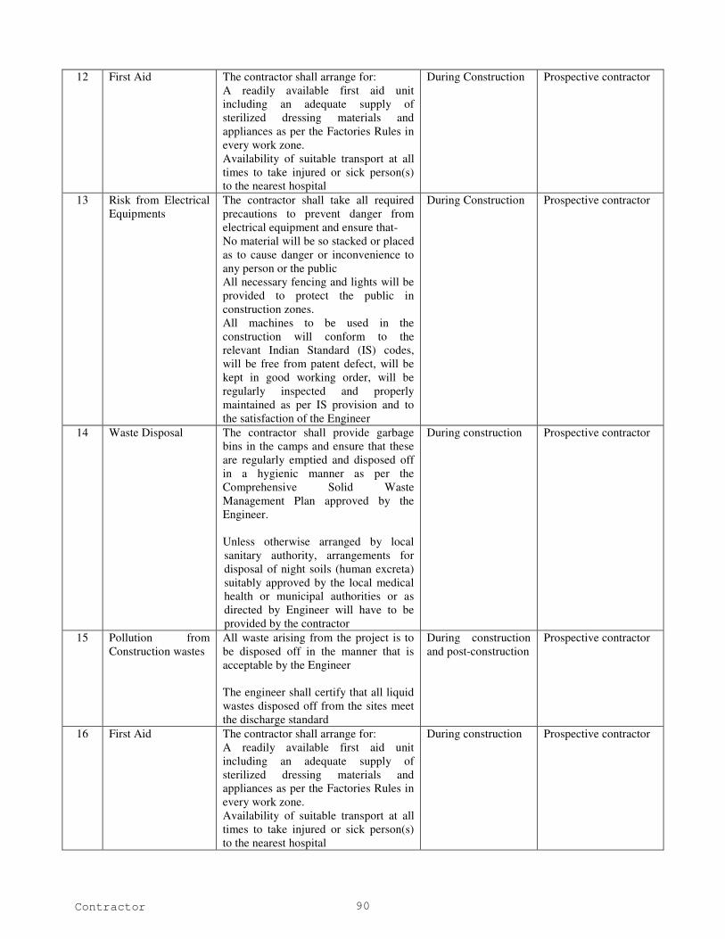
Contractor 90
12 First Aid The contractor shall arrange for:
A readily available first aid unit
including an adequate supply of
sterilized dressing materials and
appliances as per the Factories Rules in
every work zone.
Availability of suitable transport at all
times to take injured or sick person(s)
to the nearest hospital
During Construction Prospective contractor
13 Risk from Electrical
Equipments
The contractor shall take all required
precautions to prevent danger from
electrical equipment and ensure that-
No material will be so stacked or placed
as to cause danger or inconvenience to
any person or the public
All necessary fencing and lights will be
provided to protect the public in
construction zones.
All machines to be used in the
construction will conform to the
relevant Indian Standard (IS) codes,
will be free from patent defect, will be
kept in good working order, will be
regularly inspected and properly
maintained as per IS provision and to
the satisfaction of the Engineer
During Construction Prospective contractor
14 Waste Disposal The contractor shall provide garbage
bins in the camps and ensure that these
are regularly emptied and disposed off
in a hygienic manner as per the
Comprehensive Solid Waste
Management Plan approved by the
Engineer.
Unless otherwise arranged by local
sanitary authority, arrangements for
disposal of night soils (human excreta)
suitably approved by the local medical
health or municipal authorities or as
directed by Engineer will have to be
provided by the contractor
During construction Prospective contractor
15 Pollution from
Construction wastes
All waste arising from the project is to
be disposed off in the manner that is
acceptable by the Engineer
The engineer shall certify that all liquid
wastes disposed off from the sites meet
the discharge standard
During construction
and post-construction
Prospective contractor
16 First Aid The contractor shall arrange for:
A readily available first aid unit
including an adequate supply of
sterilized dressing materials and
appliances as per the Factories Rules in
every work zone.
Availability of suitable transport at all
times to take injured or sick person(s)
to the nearest hospital
During construction Prospective contractor

Contractor 91
17 Protection of top soil The top soil to be protected and
compacted after completion of work,
where the pipelines run, including open
lands and agricultural lands
During construction Prospective contractor
18 Laying of pipeline Adequate precautions should be taken
while laying the water supply mains to
avoid the possibility of cross
connection with sewer lines
During construction Prospective contractor
19 Traffic diversion Before taking up of construction
activity, a Traffic Control Plan shall be
devised and implemented to the
satisfaction of the Engineer.
Construction shall be taken phase-wise
so that sections are available for traffic
Temporary diversion will be provided
with the approval of the engineer. The
Detailed traffic control plans prepared
and submitted to the engineers for
approval one week prior to
commencement of works shall contain
details of temporary diversion, details
of arrangements for construction under
traffic, details of traffic arrangement
after cessation of work each day,
SIGNAGES, safety measures for
transport of hazardous materials and
arrangements of flagmen.
The arrangement for the temporary
diversion of the land shall ensure to
minimize the environmental impacts
like loss of vegetation, productive
lands etc., prior to the finalization of
diversion and detours.
Special consideration will be given to
the preparation of the traffic control
plan for safety of pedestrians and
workers at night.
The contractor will ensure that the
diversion/detour is always maintained
in running condition, particularly
during the monsoon to avoid disruption
to traffic flow. He shall inform local
community of changes to traffic routes,
conditions and pedestrians access
arrangements.
This plan will be periodically reviewed
with respect to site conditions.
The temporary traffic detour will be
kept free of dust by frequent
application of water.
During construction Prospective contractor
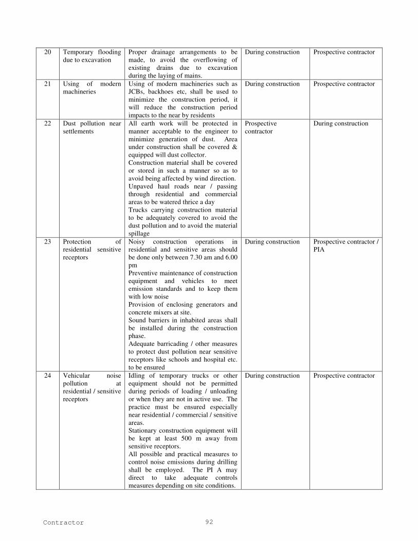
Contractor 92
20 Temporary flooding
due to excavation
Proper drainage arrangements to be
made, to avoid the overflowing of
existing drains due to excavation
during the laying of mains.
During construction Prospective contractor
21 Using of modern
machineries
Using of modern machineries such as
JCBs, backhoes etc, shall be used to
minimize the construction period, it
will reduce the construction period
impacts to the near by residents
During construction Prospective contractor
22 Dust pollution near
settlements
All earth work will be protected in
manner acceptable to the engineer to
minimize generation of dust. Area
under construction shall be covered &
equipped will dust collector.
Construction material shall be covered
or stored in such a manner so as to
avoid being affected by wind direction.
Unpaved haul roads near / passing
through residential and commercial
areas to be watered thrice a day
Trucks carrying construction material
to be adequately covered to avoid the
dust pollution and to avoid the material
spillage
Prospective
contractor
During construction
23 Protection of
residential sensitive
receptors
Noisy construction operations in
residential and sensitive areas should
be done only between 7.30 am and 6.00
pm
Preventive maintenance of construction
equipment and vehicles to meet
emission standards and to keep them
with low noise
Provision of enclosing generators and
concrete mixers at site.
Sound barriers in inhabited areas shall
be installed during the construction
phase.
Adequate barricading / other measures
to protect dust pollution near sensitive
receptors like schools and hospital etc.
to be ensured
During construction Prospective contractor /
PIA
24 Vehicular noise
pollution at
residential / sensitive
receptors
Idling of temporary trucks or other
equipment should not be permitted
during periods of loading / unloading
or when they are not in active use. The
practice must be ensured especially
near residential / commercial / sensitive
areas.
Stationary construction equipment will
be kept at least 500 m away from
sensitive receptors.
All possible and practical measures to
control noise emissions during drilling
shall be employed. The PI A may
direct to take adequate controls
measures depending on site conditions.
During construction Prospective contractor
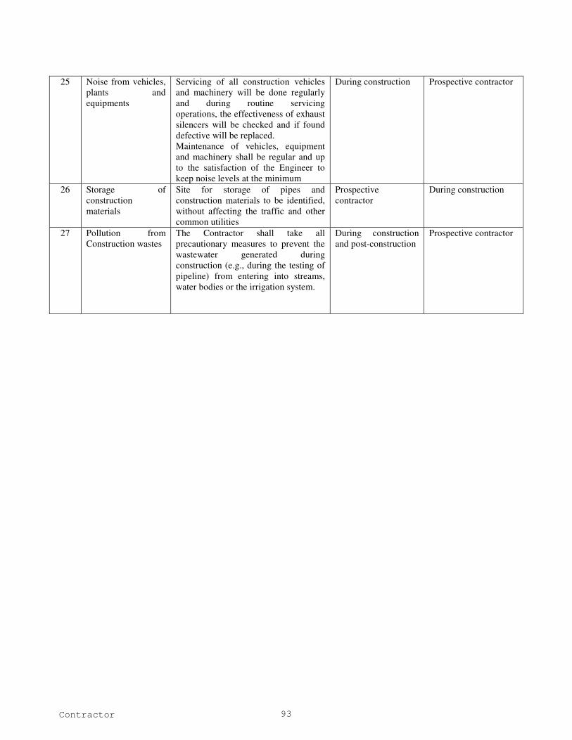
Contractor 93
25 Noise from vehicles,
plants and
equipments
Servicing of all construction vehicles
and machinery will be done regularly
and during routine servicing
operations, the effectiveness of exhaust
silencers will be checked and if found
defective will be replaced.
Maintenance of vehicles, equipment
and machinery shall be regular and up
to the satisfaction of the Engineer to
keep noise levels at the minimum
During construction Prospective contractor
26 Storage of
construction
materials
Site for storage of pipes and
construction materials to be identified,
without affecting the traffic and other
common utilities
Prospective
contractor
During construction
27 Pollution from
Construction wastes
The Contractor shall take all
precautionary measures to prevent the
wastewater generated during
construction (e.g., during the testing of
pipeline) from entering into streams,
water bodies or the irrigation system.
During construction
and post-construction
Prospective contractor