
SECTION 5 - mgf.ltd.uk · SHEET PILES MGF TECHNICAL FILE 5.1.5 Issue 3 Extractors MGF manufacture...
27
01942 402 704 [email protected] www.mgf.ltd.uk MGF Sheet Piles 5.1 MGF Trench Sheets 5.2 MGF Walers and Struts 5.3 HYDRAULIC WALER SYSTEMS AND SHEET PILES SECTION 5
Transcript of SECTION 5 - mgf.ltd.uk · SHEET PILES MGF TECHNICAL FILE 5.1.5 Issue 3 Extractors MGF manufacture...

01942 402 [email protected]
MGF Sheet Piles 5.1
MGF Trench Sheets 5.2
MGF Walers and Struts 5.3
HYDRAULIC WALER SYSTEMS AND SHEET PILES
SECTION 5

Tel. 01942 402 704
MG
F TE
CH
NIC
AL F
ILE
2Issue 3
MGF Trench Sheets used in combination with the MGF Tie Back and Waler System to retain canal banks

SHEE
T PI
LES
MG
F TE
CH
NIC
AL F
ILE
5.1.1Issue 3
Description MGF interlocking steel sheet piles are a high strength sheeting system generally specified to support the vertical faces of large excavations between 4m and 13m in depth. The piles are fully compatible with the MGF shoring product range. Interlocking piles should be specified to prevent water ingress where significant groundwater is anticipated. They are installed using specialist equipment such as impact hammers, vibrating pile drivers or hydraulic presses (subject to suitability of the equipment for driving the piles into the anticipated ground conditions). The piles are sourced in 0.5m increments of length from major EU steel mills in grade S270 to S390 (BS EN 10248 Part 1). Handling holes are provided as standard at one end of the sheet. MGF design and specify the piles in accordance with the relevant standards and guidance documents listed in section 1. MGF can supply the piles with a range of compatible lifting chains, Quick Release Shackles, extractors, Edgesafe edge protection panels, Laddersafe access platforms and pole ladders and Davitsafe retrieval/fall arrest systems.
Product Notes
1. Interlocking steel sheet piles should only be specified, installed and removed by competent persons using specialist equipment selected to suit the size of sheet pile and the anticipated ground conditions/site constraints.
2. Sheet piles are heavy and difficult to handle/pitch on site and these operations should only be carried out by experienced banksmen. Always ensure that the excavator has sufficient reach to safely lift the sheets, the piles are not lifted over personnel and that the trailing ropes on Quick Release Shackles cannot snag. Great care should be taken to avoid trapping fingers whilst pitching the piles. Additional care must be taken in windy conditions when it is recommended that at least 2 persons are used to pitch the piles.
3. A range of corner piles are available when significant groundwater is anticipated to maintain full interlocks along the perimeter of cofferdam structures. Waterproof clutch sealants can be supplied by MGF to provide additional water tightness.
4. For cantilevered sheet pile wall designs a relevant borehole log must always be provided extending well beyond the toe of the sheet.
5. When stacking piles on site it is recommended that they are placed in bundles of no more than 6 sheets and staggered on timber spacers to allow for ease of handling and to minimise the risk of trapping hands/fingers.
6. Other pile lengths, profiles and grades are available upon request.
7. In order to assist installation MGF can supply guide walings. For availability and details contact MGF direct.
8. Sheet piles must only be removed using MGF extractors. Use of a quick release shackle for extraction will lead to damage of the spring mechanism.
9. Interlocking sheet piles are often specified for permanent works applications and are capable of providing significant vertical foundation support to structures. Contact MGF Design for more details.

Tel. 01942 402 704
MG
F TE
CH
NIC
AL F
ILE
SHEE
T PI
LES
5.1.2Issue 3
VL602 product ID - 3.02
Available lengths:
5m-8m
VL603 product ID - 3.03
Available lengths:
6m-10m
VL604 product ID - 3.04
Available lengths:
7m-10m
Recommended for easy driving
conditions
Recommended for easy to normal driving conditions
Recommended for normal driving
conditions
N.B. Choice of a sheet profile is normally governed by driveability considerations
N.B. - Values in brackets apply when sheets are not fully interlocked * Permanent capacity does not take into account loss of thickness due to corrosion
Sheet Type
Material Grade
Max SWL (kNm/m) Section Modulus (cm3/m)
Moment of Inertia (cm4/m)
Weight per m (kg/m)
Weight per m2 (kg/m2)Temporary Permanent*
VL602 S270 GP 169.0 (86.2) 152.1 (77.6) 845 (431) 13075 (4582) 54.3 90.5VL603 S270 GP 236.0 (99.0) 212.4 (89.1) 1180 (495) 18251 (5803) 64.8 108.0VL604 S270 GP 324.0 (139.6) 291.6 (125.6) 1620 (698) 30726 (9628) 74.1 123.5VL605 S270 GP 401.2 (158.4) 361.1 (142.6) 2006 (792) 41127 (12038) 82.4 137.3VL606 S270 GP 501.2 (166.6) 451.1 (149.9) 2506 (833) 52631 (13505) 94.8 158.0VL602 S355 GP 219.7 (112.1) 194.4 (99.1) 845 (431) 13075 (4582) 54.3 90.5VL603 S355 GP 306.8 (128.7) 271.4 (113.9) 1180 (495) 18251 (5803) 64.8 108.0VL604 S355 GP 421.0 (181.5) 372.6 (160.5) 1620 (698) 30726 (9628) 74.1 123.5VL605 S355 GP 521.6 (205.9) 461.4 (182.2) 2006 (792) 41127 (12038) 82.4 137.3VL606 S355 GP 651.6 (216.6) 576.4 (191.6) 2506 (833) 52631 (13505) 94.8 158.0
GU8N S390 GP 223.3 200.2 770 12010 48.5 80.9GU13N S390 GP 368.3 330.2 1270 26590 59.9 99.8GU16N S390 GP 484.3 434.2 1670 35950 72.6 121.0GU18N S390 GP 522.0 468.0 1800 38650 76.9 128.2GU21N S390 GP 597.4 535.6 2060 46380 81.9 136.5GU23N S390 GP 677.2 607.1 2335 52510 90.4 150.7
VL Sheet Piles

SHEE
T PI
LES
MG
F TE
CH
NIC
AL F
ILE
5.1.3Issue 3
VL606 product ID - 3.06
Available lengths:
8m-13m
VL605 product ID - 3.05
Available lengths:
7m-12m
Recommended for normal to hard driving conditions
Recommended for hard driving
conditions
GU Sheet Piles
GU8Nproduct ID - 3.11
Available lengths:
5m-8m
Recommended for easy driving
conditions
GU13Nproduct ID - 3.12
Available lengths:
6m-9m
Recommended for easy to normal driving conditions
GU16Nproduct ID - 3.13
Available lengths:
7m-10m
Recommended for normal driving
conditions
GU18Nproduct ID - 3.18
Available lengths:
7m-12m
Recommended for normal driving
conditions
Further sheet lengths can be supplied. Please contact MGF for details

Tel. 01942 402 704
MG
F TE
CH
NIC
AL F
ILE
SHEE
T PI
LES
5.1.4Issue 3
BS20 The BS20 Corner Pile is suitable for 90° internal corners and is
compatible with all the MGF pile profiles.
Angle = 90° Mass per Metre = 14.4kg/m
Corner Piles
Omega The Omega Corner Pile is suitable for 90° to 135° internal corners
and is compatible with all the MGF pile profiles.
Angle = 90° - 135° Mass per Metre = 18.0kg/m
MGF CAD blocks are available to assist with sizing of interlocked cofferdams utilising various combinations of corner piles.
Recommended for normal to hard driving conditions
Recommended for hard driving
conditions
GU21Nproduct ID - 3.14
Available lengths:
7m-12m
GU23Nproduct ID - 3.19
Available lengths:
8m-13m
Each sheet is supplied with Φ40 handling hole compatible with MGF 2t and 6t pitching shackles and extractors.
Extra holes can be provided upon request.
Larssen Interlock Detail The interlock allows for up to 5° horizontal deviation between each successive sheet.

SHEE
T PI
LES
MG
F TE
CH
NIC
AL F
ILE
5.1.5Issue 3
Extractors
MGF manufacture and supply 6t SWL pile extractors for the safe removal of MGF
sheet piles.
Extractors should always be inspected for damage prior to each use. Prior to extraction
ensure that the pin is located in the pile/sheet handling hole with an r-clip attached,
and fully locked to prevent accidental release during extraction. Extractors are designed
to cope with large extraction forces but must not be violently shaken or snatched.
Quick Release Shackles
MGF manufacture and supply 6t Quick Release Shackles (QRS’s) for the safe and efficient
handling and pitching of MGF sheet piles.
MGF QRS’s are supplied with rope lines to allow the release of piles/sheets once pitched.
All MGF pitching shackles feature a simple safety mechanism that prevents the accidental
release of the shackle in the event the rope snags. A short length of chain is attached from the lever arm of the shackle to a metal ring, to
which the nylon rope line is attached. When this is in use it ensures that the rope cannot snag
and release the mechanism.QRS’s should always be inspected for damage
prior to each use - especially the spring mechanism, which can be easily damaged
by use as an extractor (for which they are not designed).
They must not be violently shaken or snatched prior to lifting piles always ensure pin is fully
engaged.
Desc. Product ID Weight (kg)6t 2.406 27
Desc. Product ID Weight (kg)6t 2.106 26
Tel. 01942 402 704
MG
F TE
CH
NIC
AL F
ILE
SHEE
T PI
LES
5.1.6Issue 3
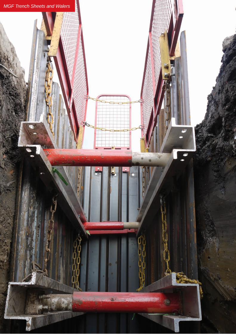
MGF Trench Sheets and Walers

TREN
CH
SH
EETS
MG
F TE
CH
NIC
AL F
ILE
5.2.1Issue 3
Description MGF trench sheets are available in a wide range of profiles and lengths and are generally specified to support the vertical faces of most small to medium sized trenches and excavations between 1m and 9m in depth. The sheets are primarily designed to be handled and installed by excavators using the bucket to drive the sheets vertically into the ground and are fully compatible with the complete MGF shoring range. The sheets are manufactured in the UK by MGF in a variety of steel grades to BS EN 10249 Part 1. The range includes both lapped and interlocking systems. Handling holes are provided as standard at one end of the sheet. MGF design and specify the sheets in accordance with the relevant standards and guidance documents listed in section 1. MGF can supply the sheets with a range of compatible driving caps, Drivesafe quick hitch driving caps, lifting chains, Quick Release Shackles, extractors, Edgesafe edge protection panels, Laddersafe access platforms and pole ladders and Davitsafe retrieval/fall arrest systems.
Product Notes1. Trench sheets should only be installed and removed by competent persons using excavators specified
to suit the size of trench sheet and the anticipated ground conditions/site constraints.
2. Trench sheets are heavy and difficult to handle/pitch on site and these operations should only be carried out by experienced banksmen. Always ensure that the sheets are not lifted over personnel and that the trailing ropes on Quick Release Shackles cannot snag. Great care should be taken to avoid trapping fingers whilst pitching the sheets. Additional care must be taken in windy conditions when it is recommended that at least 2 persons are used to pitch the sheets.
3. MGF strongly recommend that a driving cap is always used to prevent unnecessary damage to the tops of the trench sheet when being driven into the ground using the excavator bucket.
4. When stacking sheets on site it is recommended that they are placed in bundles of no more than 6 sheets and staggered on timber spacers to allow for ease of handling and to minimise the risk of trapping hands/fingers.
5. Other sheet lengths, profiles and grades are available upon request. MGF can also provide sheets for sale with a galvanised finish.
6. In order to assist installation MGF can supply guide walings and piling frames. For availability and details contact MGF direct.
7. Trench sheets must only be removed using MGF extractors. Use of a quick release shackle for extraction will lead to damage of the spring mechanism.
8. MGF offer a complete re-roll and refurbishment facility for damaged trench sheets.
9. MGF interlocking trench sheets can provide limited protection against groundwater ingress and should always be used with caution where high water flows are anticipated.
10. Trench sheets are generally not recommended for cantilevered designs as deflections can be a significant issue.
Tel. 01942 402 704
MG
F TE
CH
NIC
AL F
ILE
TREN
CH
SH
EETS
5.2.2Issue 3
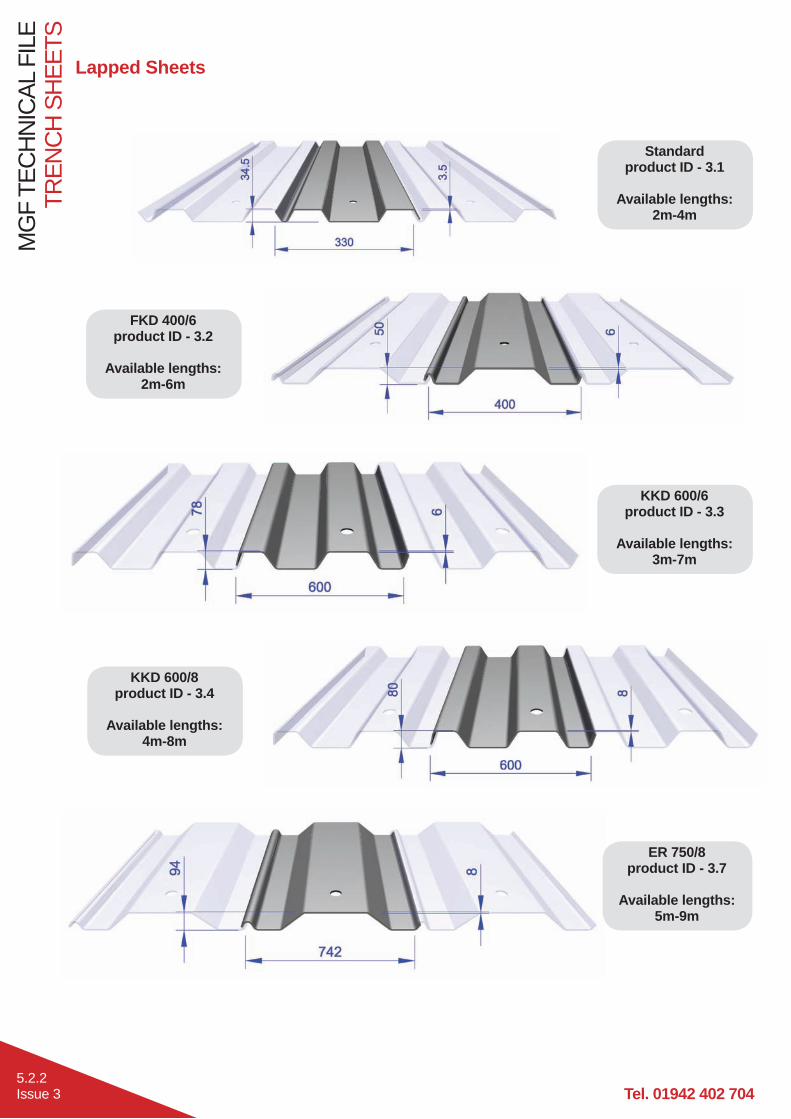
Standard product ID - 3.1
Available lengths:
2m-4m
FKD 400/6 product ID - 3.2
Available lengths:
2m-6m
KKD 600/6 product ID - 3.3
Available lengths:
3m-7m
KKD 600/8 product ID - 3.4
Available lengths:
4m-8m
Lapped Sheets
ER 750/8 product ID - 3.7
Available lengths:
5m-9m

TREN
CH
SH
EETS
MG
F TE
CH
NIC
AL F
ILE
5.2.3Issue 3
Sheet Type Material Grade
Max SWL (kNm/m)
Section Modulus (cm3/m)
Moment of Inertia (cm4/m)
Weight per m (kg/m)
Weight per m2 (kg/m2)
Standard S235 JRC 7.8 45.7 84.8 11.3 34.4Standard S275 JRC 9.3 45.7 84.8 11.3 34.4FKD 400/6 S275 JRC 19.8 98.8 250.1 22.1 55.3KKD 600/6 S275 JRC 36.8 184 717.5 37.5 62.5KKD 600/8 S275 JRC 48.4 242 947 50 83.3ER 750/8 S355 J0C 66.0 254 1197.2 53.6 72.2
L8 S235 JRC 9.1 52.3 98.15 14.4 33.2FLP 600/3.5 S275 JRC 33.5 183 1215.1 23.1 38.5FLP 600/6 S275 JRC 61.2 306 2067.2 38.8 64.6
L8 product ID - 3.9
Available lengths:
SALE ONLY
FLP 600/6 product ID - 3.5
Available lengths:
4m-7m
Interlocking Sheets
Max SWL based on temporary works allowable stresses
FLP 600/3.5 product ID - 3.8
Available lengths:
SALE ONLY
All MGF FLP, ER, KKD and FKD trench sheets are supplied with 2 handling holes at the top of the sheet. Extra handling holes to any sheet can be provided upon request.
Tel. 01942 402 704
MG
F TE
CH
NIC
AL F
ILE
TREN
CH
SH
EETS
5.2.4Issue 3
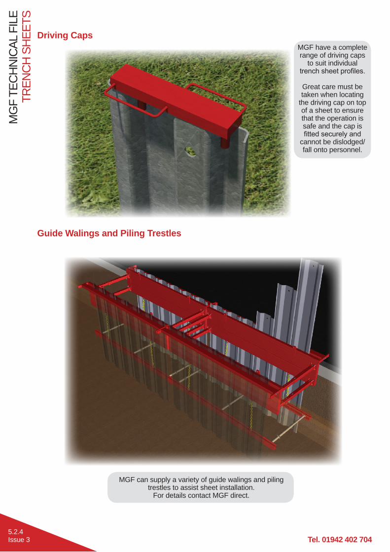
MGF have a complete range of driving caps
to suit individual trench sheet profiles.
Great care must be taken when locating
the driving cap on top of a sheet to ensure that the operation is safe and the cap is fitted securely and
cannot be dislodged/fall onto personnel.
Driving Caps
Guide Walings and Piling Trestles
MGF can supply a variety of guide walings and piling trestles to assist sheet installation.
For details contact MGF direct.

TREN
CH
SH
EETS
MG
F TE
CH
NIC
AL F
ILE
5.2.5Issue 3
Extractors
Quick Release Shackles
Desc. Product ID Weight (kg)2t 2.403 236t 2.406 27
Desc. Product ID Weight (kg)2t 2.102 223t 2.103 246t 2.106 26
MGF manufacture and supply 2t and 6t SWL pile extractors for the safe removal of MGF
trench sheets.
Extractors should always be inspected for damage prior to each use. Prior to extraction
ensure that the pin is located in the pile/sheet handling hole with an r-clip attached,
and fully locked to prevent accidental release during extraction. Extractors are designed
to cope with large extraction forces but must not be violently shaken or snatched.
MGF manufacture and supply 2t, 3t and 6t Quick Release Shackles (QRS’s) for the safe
and efficient handling and pitching of MGFs trench sheets.
MGF QRS’s are supplied with rope lines to allow the release of piles/sheets once pitched.
All MGF pitching shackles feature a simple safety mechanism that prevents the accidental
release of the shackle in the event the rope snags. A short length of chain is attached from the lever arm of the shackle to a metal ring, to
which the nylon rope line is attached. When this is in use it ensures that the rope cannot snag
and release the mechanism.QRS’s should always be inspected for damage
prior to each use - especially the spring mechanism, which can be easily damaged
by use as an extractor (for which they are not designed).
They must not be violently shaken or snatched prior to lifting piles always ensure pin is fully
engaged.

Tel. 01942 402 704
MG
F TE
CH
NIC
AL F
ILE
TREN
CH
SH
EETS
5.2.6Issue 3
Drivesafe
Drivesafe Type
Product ID
Weight (kg)
Geith Quick Coupler
Miller Quick Coupler Hill TEFRA Quick Coupler
65mm 4.500 100 QC65H, QH65M Range 4 Tefra 13t80mm 4.501 126 QC80H, QH80M Range 5, Range 6 Tefra 16t, Tefra 21t, Tefra 25t
MGF Drivesafe is an excavator attachment designed to be used for the safe and efficient driving of Trench Sheets using the push and dig method.
Compatible with a range of excavators, ranging in capacity from 13t to 25t, the Drivesafe units can be quickly attached to the excavator boom using the quick hitch mechanism.
The Drivesafe unit is an alternative to using a Driving Cap, and avoids the need for working at height. The sheets are pitched, as normal, using an MGF Quick Release Shackle. Once the sheet is pitched then the Drivesafe should apply slow, steady pressure to the top of the sheet to drive it into the ground. The guide plates on the underside of the unit are there to re-align the sheet if needed.
Before use, ensure the Drivesafe is compatible with the quick hitch bracket on which it is to be used (see table below).
For a full Safe System of Work document and animation, please see the MGF Website.

WAL
ERS
AND
STR
UTS
MG
F TE
CH
NIC
AL F
ILE
5.3.1Issue 3
DescriptionSimple to assemble, two sided, hydraulic bracing system designed to be used with steel trench sheets to horizontally brace small trenches for the safe installation of utilities. The range comprises seven types of waler rail and two sizes of hydraulic waler strut together with 0.25m, 0.5m and 1.0m strut extension bars. The system can support trench widths of 0.6m to 3.8m and is normally installed using excavators. MGF also provide Vertishore, a light weight hydraulic system used to brace small trenches vertically.
Fabricated from either grade S275/S355/S460 steel profiles or grade 6082T6 alumium profiles, the waler rails are attached to the hydraulic struts using simple pin and retaining clip assemblies. The 250kN hydraulic struts attach to the 152 UC Waler using clamps or cleats. Each strut contains a hydraulic ram with between 300mm and 670mm of stroke. Connecting the rams (via hydraulic hoses) to an MGF hand operated hydraulic pump unit containing hydraulic shoring fluid allows the trench widths to be quickly and easily adjusted to suit the excavation dimensions. Once the trench frames are fully assembled and located at the correct line and level, the rams are pre-loaded against the trench sheets using a hydraulic pump. Pre-loading of the legs ensures the frame cannot slip and minimises the extent of potential ground movements. Self sealing quick release valves and mechanical isolation valves ensure that the hydraulic ram pressure cannot be accidently released once installed. Handling and restraining points are provided on each waler to assist assembly / removal and to allow the brace to be supported off MGF restraining chains attached to the trench sheets by hooks.
MGF can supply the systems with a full range of suitable handling and restraining chains, Edgesafe edge protection panels, Endsafe end protection panels and struts, Laddersafe access platforms and pole ladders, Davitsafe retrieval / fall arrest systems, hydraulic pump installation kits (including bio-degradable shoring fluid and hydraulic hoses) and confined spaces regime equipment.
Manufactured and designed in accordance with BS EN 14653:2005 PARTS 1 and 2 Manually operated Shoring Systems for Groundwork Support and BS 5975 (2008) Code of Practice for Temporary Works Procedures and the Permissible Stress Design of Falsework.
Product Notes1. Waler and trench strut systems should only be installed and removed by competent persons in accordance
with a site specific detailed design & installation sequence and MGF installation guidelines. N.B. Struts can be located at a variety of positions along the length of the waler. The exact location of the struts will determine the strength of the waler system.
2. Installation is normally carried out by lowering the assembled frame to the correct installation level and pre-loading each strut in turn to ensure that the frame is pressed firmly against the trench sheets and cannot slip. Max pre-load pressure of 100Bar (1500psi) must not be exceeded.
3. Restraining chains are hung off the trench sheets and attached to the waler to assist assembly / removal of the frame and ensure vertical support is provided at all times. All the supplied restraining chains should be installed (min 2 per waler) and adjusted to ensure an even vertical load distribution. Restraining chains should never be used for lifting nor solely relied upon to suspend loads above personnel.
4. Ensure all hydraulic ram isolation valves are closed and all strut pins in place and secured using the retaining clips provided prior to commencing works.
5. Individual walers and struts should be visually inspected for damage, excessive deflection or loss of ram pressure prior to entering the excavation.
6. Walers and struts should always be installed square and plumb to the excavation walls ensuring contact with all the inward facing trench sheet pans. If this is not possible any gaps must be securely packed by using hardwood wedges prior to final pre-loading of the hydraulic rams.
7. Safe access/egress, edge protection (for personnel) and barrier protection (for plant) should always be considered.
8. Prior to removal of systems all hydraulic rams must be released and retracted to avoid the need for excessive extraction forces and to avoid damaging the struts.
9. No matter how much care is taken during the installation and removal of waler and strut trench systems some ground movement will occur in the areas immediately surrounding the excavation. Great care must be taken when specifying these systems for use adjacent to existing structures and services.
10. Ends of trench runs should always be battered back at a safe angle or end protection panels/struts installed (see section 6).

Tel. 01942 402 704
MG
F TE
CH
NIC
AL F
ILE
WAL
ERS
AND
STR
UTS
5.3.2Issue 3
MGF Pole Ladder
MGF Endsafe Panel - See Section 6
MGF Steel Walers
MGF Laddersafe - See Section 6
MGF Edgesafe - See Section 6
MGF Trench Sheets - See Section 5.2
WAL
ERS
AND
STR
UTS
MG
F TE
CH
NIC
AL F
ILE
5.3.3Issue 3
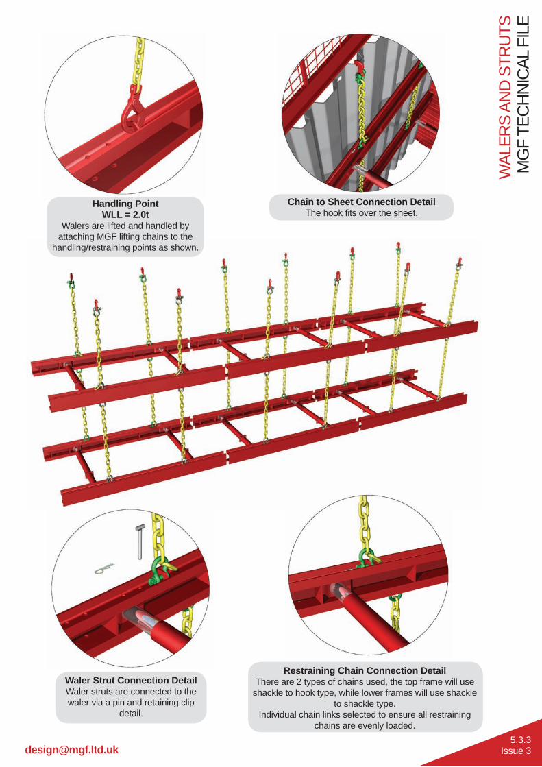
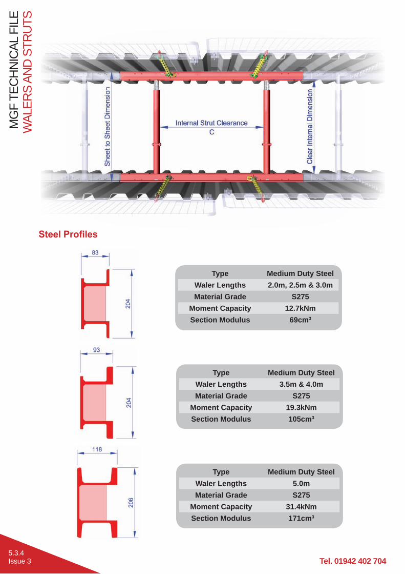
Restraining Chain Connection DetailThere are 2 types of chains used, the top frame will use
shackle to hook type, while lower frames will use shackle to shackle type.
Individual chain links selected to ensure all restraining chains are evenly loaded.
Waler Strut Connection DetailWaler struts are connected to the waler via a pin and retaining clip
detail.
Chain to Sheet Connection DetailThe hook fits over the sheet.
Handling PointWLL = 2.0t
Walers are lifted and handled by attaching MGF lifting chains to the
handling/restraining points as shown.
Tel. 01942 402 704
MG
F TE
CH
NIC
AL F
ILE
WAL
ERS
AND
STR
UTS
5.3.4Issue 3
Type Medium Duty SteelWaler Lengths 2.0m, 2.5m & 3.0mMaterial Grade S275
Moment Capacity 12.7kNmSection Modulus 69cm3
Type Medium Duty SteelWaler Lengths 3.5m & 4.0mMaterial Grade S275
Moment Capacity 19.3kNmSection Modulus 105cm3
Type Medium Duty SteelWaler Lengths 5.0mMaterial Grade S275
Moment Capacity 31.4kNmSection Modulus 171cm3
Steel Profiles

WAL
ERS
AND
STR
UTS
MG
F TE
CH
NIC
AL F
ILE
5.3.5Issue 3
Type Heavy Duty SteelWaler Lengths 3.0m - 5.0mMaterial Grade S460
Moment Capacity 40.5kNmSection Modulus 132cm3
Type Medium Duty AluminiumWaler Lengths 2.0m - 4.0mMaterial Grade 6082T6
Moment Capacity 18.6kNmSection Modulus 111cm3
Aluminium Profiles
Type 152UCWaler Lengths 5.0mMaterial Grade S355
Moment Capacity 73.1kNmSection Modulus 309cm3
Type 152UCWaler Lengths 6.0mMaterial Grade S355
Moment Capacity 147.2kNmSection Modulus 622cm3

Tel. 01942 402 704
MG
F TE
CH
NIC
AL F
ILE
WAL
ERS
AND
STR
UTS
5.3.6Issue 3
Medium Duty Steel Walers Sheet to Sheet (mm)
Desc. Waler Weight (kg) Code L
(mm)W
(mm)C*MAX (mm) Min Max Assembled
Weight** (kg)
2000 70 1.120 2000 83 1420 565 3800 1762500 88 1.125 2500 83 1920 565 3800 2123000 97 1.130 3000 83 2420 565 3800 2303500 112 1.135 3500 93 2920 565 3800 2604000 129 1.240 4000 93 3420 565 3800 2945000 180 1.250 5000 116 4370 565 3800 396
* Depends on strut locations** Assembled weight includes 2 No. type 800 struts
Medium Duty Steel Waler
Heavy Duty Steel Waler
Heavy Duty Steel Walers Sheet to Sheet (mm)
Desc. Waler Weight (kg) Code L
(mm)W
(mm)C*MAX (mm) Min Max Assembled
Weight** (kg)
3000 100 1.330 3000 108 2420 565 3800 2364000 133 1.340 4000 108 3420 565 3800 3025000 166 1.350 5000 108 4420 565 3800 368
* Depends on strut locations** Assembled weight includes 2 No. type 800 struts

WAL
ERS
AND
STR
UTS
MG
F TE
CH
NIC
AL F
ILE
5.3.7Issue 3
152UC Steel Waler
Medium Duty Aluminium Walers Sheet to Sheet (mm)
Desc. Waler Weight (kg) Code L
(mm)W
(mm)C*MAX (mm) Min Max Assembled
Weight** (kg)
1500 18 1.015 1500 100 1010 565 3800 722000 24 1.020 2000 100 1510 565 3800 842500 30 1.025 2500 100 1910 565 3800 963000 36 1.030 3000 100 2410 565 3800 1084000 47 1.040 4000 100 3310 565 3800 130
* Depends on strut locations** Assembled weight includes 2 No. type 800 struts
Medium Duty Aluminium Waler
152UC Steel Walers Sheet to Sheet (mm)
Desc. Waler Weight (kg) Code L
(mm)W
(mm)C*MAX (mm) Min Max Assembled
Weight** (kg)
5000 205 1.0050 5000 162 4540 950 6000 6406000 385 1.0060 6000 186 5540 975 6000 1000
* Depends on strut locations** Assembled weight includes 2 No. 250kN Hydraulic Struts

Tel. 01942 402 704
MG
F TE
CH
NIC
AL F
ILE
WAL
ERS
AND
STR
UTS
5.3.8Issue 3
80kN Single Acting Hydraulic Ram Assembly
Pump Units
Product ID 1.602 (SA)Capacity 20 litres
Shoring Fluid Houghto Safe SF25Installation Pressure 0-1500 psi
The pump is used to extend waler strut single acting hydraulic rams. The pumps contain bio-degradable Houghto Safe SF25 shoring fluid. During the Summer months the shoring fluid is diluted with water at a ratio of 3 parts water to 1 part Houghto Safe SF25. In the Winter the mix ratio is 1:1.Maximum recommended installation pressure 1500 psi (100 Bar).
Shoring fluid is pumped into the full bore side of the piston through the male QRV. Single acting cylinders cannot be retracted using a pump unit and have to be physically closed whilst releasing the male QRV.Ensure isolation valve is closed to maintain pre-load pressure and before release/connection of QRV’s.
Hydraulic Cylinder Single ActingMaterial Aluminium
Bore 50.8mmMax .Working Pressure 400 Bar (6000 psi)
Test Pressure 400 Bar (6000 psi)Approx. Working Stroke 350mm/600mm
Axial SWL 80kNMin. FOS (by test) 2
Working Temp Range -20ºC* to +50ºCApprox. Pre-Load 20kN
* Winter mix required for shoring fluid at low temps.
WAL
ERS
AND
STR
UTS
MG
F TE
CH
NIC
AL F
ILE
5.3.9Issue 3
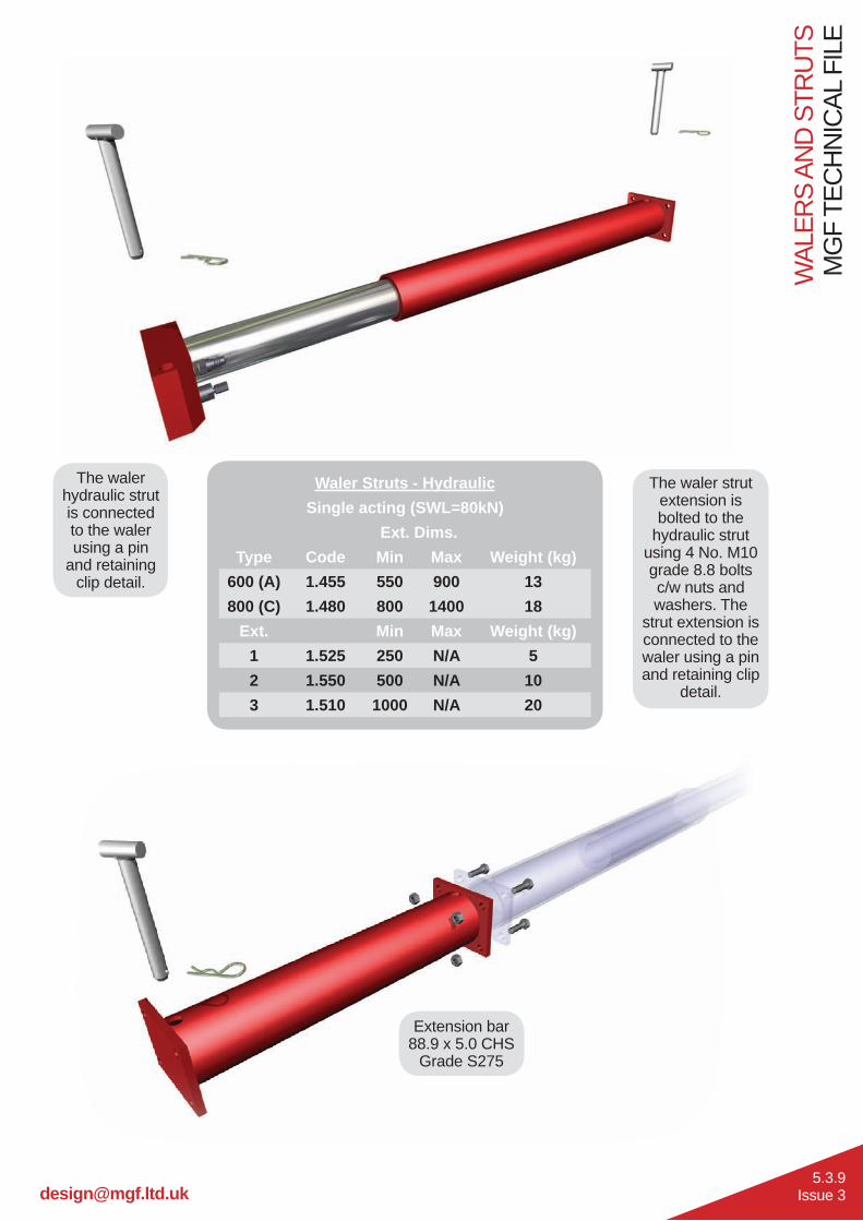
Waler Struts - Hydraulic Single acting (SWL=80kN)
Ext. Dims.Type Code Min Max Weight (kg)
600 (A) 1.455 550 900 13800 (C) 1.480 800 1400 18
Ext. Min Max Weight (kg)1 1.525 250 N/A 52 1.550 500 N/A 103 1.510 1000 N/A 20
The waler hydraulic strut is connected to the waler using a pin
and retaining clip detail.
The waler strut extension is bolted to the
hydraulic strut using 4 No. M10 grade 8.8 bolts c/w nuts and washers. The
strut extension is connected to the waler using a pin and retaining clip
detail.
Extension bar88.9 x 5.0 CHS
Grade S275
Tel. 01942 402 704
MG
F TE
CH
NIC
AL F
ILE
WAL
ERS
AND
STR
UTS
5.3.10Issue 3
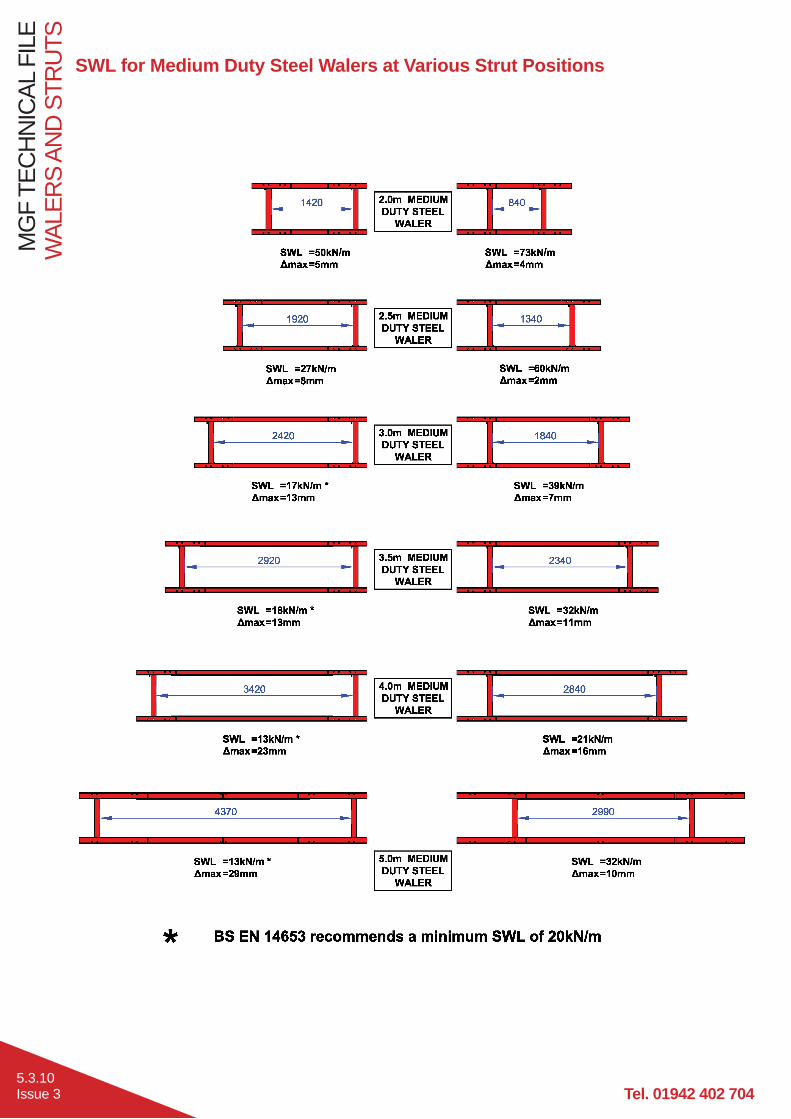
SWL for Medium Duty Steel Walers at Various Strut Positions

WAL
ERS
AND
STR
UTS
MG
F TE
CH
NIC
AL F
ILE
5.3.11Issue 3
SWL for Heavy Duty Steel Walers at Various Strut Positions
SWL for Aluminium Walers at Various Strut Positions

Tel. 01942 402 704
MG
F TE
CH
NIC
AL F
ILE
WAL
ERS
AND
STR
UTS
5.3.12Issue 3
SWL for 152 UC Steel Waler at Various Strut Positions
MGFs new 152 UC Steel Waler is designed to be used with the 200 Series 250kN Hydraulic Strut in conjunction with 152 UC Waler clamps (4.1.11). The clamps simply bolt to the endplate using 2 No. M20 bolts. Prior to connecting the struts it is recommended to loosely bolt the top 152 UC clamp, and then locate the strut on the waler, once positioned the top clamp can be fully tightened and the bottom clamp can then be installed.
On the 5.0m 152 UC Waler the struts can be positioned anywhere along the waler.
On the 6.0m 152 UC Waler the struts can be positoned anywhere inbetween the min. and max. clearance, as shown above.
When the 200 Series strut is installed in its outer most positions it can also be used as an end protection strut, allowing sheets to be installed up against the strut, enabling 3 or 4 sided excavations.
Safe Working Load for 200 Series Strut as Waler End Protection Struts (kN/m)

WAL
ERS
AND
STR
UTS
MG
F TE
CH
NIC
AL F
ILE
5.3.13Issue 3
Aluminium Vertishore
Pre-assembled, light weight, two sided hydraulic waler strut system designed to be installed from ground level directly against a soil face in the vertical plane. Suitable for trenches up to 2.0m deep and 1.4m wide. The System can be installed by one person and is usually specified for short term utilities type trench work where the ground is considered self supporting and capable of arching a min. 1.5m between preloaded hydraulic vertical supports for the duration of the works. Backing boards are available to prevent localised pockets of loose material entering the excavation. Personnel should only enter and work in the space between two vertishores. A competent person should always inspect the excavation before allowing access to ensure that all the struts are pre-loaded and bearing directly onto the soil, the exposed soil faces are self supporting with no evidence of water ingress or very loose material. Vertical support must be provided at a max. 1.5m horizontally. Always install and remove the system from ground level and away from any potentially unstable edges. Vertishores are supplied with an installation kit, including a pump unit, lowering hook and valve release tool.
Available hydraulic strutsType A : 550-900mm
Type B1: 850-1375mm
SWL = 20kN/m (on Vertishore)
* Assembled weight (excluding boards) with type A struts
Desc. Product ID Weight* (kg)1500 1.014 282000 1.013 35