Section 430 Portland Cement Concrete Pavement 1 Section 430—Portland Cement Concrete Pavement...
19
Page 1 Section 430—Portland Cement Concrete Pavement 430.1 General Description This work includes constructing pavement composed of Portland cement concrete, with or without reinforcement as specified, on a prepared subgrade or subbase course. Follow the requirements of these Specifications and conform to the lines, grades, thicknesses, and cross sections shown on the Plans or by the Engineer. 430.1.01 Definitions General Provisions 101 through 150. 430.1.02 Related References A. Standard Specifications Section 106—Control of Materials Section 152—Field Laboratory Building Section 431—Grind Concrete Pavement Section 461—Sealing Roadway and Bridge Joints and Cracks Section 500—Concrete Structures Section 800—Coarse Aggregate Section 801—Fine Aggregate Section 830—Portland Cement Section 831—Admixtures Section 832—Curing Agents Section 833—Joint Fillers and Sealers Section 853—Reinforcement and Tensioning Steel Section 880—Water Section 886—Epoxy Resin Adhesives B. Referenced Documents AASHTO T 126 AASHTO T 97 AASHTO T 22 AASHTO T 23 ACI 214 ASTM C 94, Requirements for Uniformity ASTM C 684, Method A GDT 26 GDT 27
Transcript of Section 430 Portland Cement Concrete Pavement 1 Section 430—Portland Cement Concrete Pavement...
Page 1
Section 430—Portland Cement Concrete Pavement
430.1 General Description
This work includes constructing pavement composed of Portland cement concrete, with or without reinforcement as
specified, on a prepared subgrade or subbase course.
Follow the requirements of these Specifications and conform to the lines, grades, thicknesses, and cross sections shown on
the Plans or by the Engineer.
430.1.01 Definitions
General Provisions 101 through 150.
430.1.02 Related References
A. Standard Specifications
Section 106—Control of Materials
Section 152—Field Laboratory Building
Section 431—Grind Concrete Pavement
Section 461—Sealing Roadway and Bridge Joints and Cracks
Section 500—Concrete Structures
Section 800—Coarse Aggregate
Section 801—Fine Aggregate
Section 830—Portland Cement
Section 831—Admixtures
Section 832—Curing Agents
Section 833—Joint Fillers and Sealers
Section 853—Reinforcement and Tensioning Steel
Section 880—Water
Section 886—Epoxy Resin Adhesives
B. Referenced Documents
AASHTO T 126
AASHTO T 97
AASHTO T 22
AASHTO T 23
ACI 214
ASTM C 94, Requirements for Uniformity
ASTM C 684, Method A
GDT 26
GDT 27
Section 430—Portland Cement Concrete Pavement
Page 2
GDT 28
GDT 31
GDT 32
GDT 72
GDT 78
SOP 34
Report form, furnished by the Engineer
Requests for certification
430.1.03 Submittals
A. Profilograph Equipment and Operator Certification
Include in the Contract Unit Bid Price the cost to furnish and operate a Rainhart (Model 860) Profilograph to measure
pavement profile deviations.
Before paving, ensure that the operator and the profilograph are certified by the Office of Materials and Research in
accordance with Standard Operating Procedure No. 34, Certification of Contractor Personnel and Equipment for
Smoothness Testing of Portland Cement Concrete Pavement with the Rainhart Profilograph. Certification includes a
mechanical check of the profilograph functions and a written examination by the operator.
Request certification in writing to the Office of Materials and Research at least two weeks before it is needed.
B. Concrete Design
Submit for approval a concrete design that is prepared by a testing laboratory approved by the Office of Materials and
Research. The Contractor will transmit the design to the Engineer for approval at least 35 days before use.
C. Approval of Mix Design Proportions
Obtain approval from the Office of Materials and Research for proposed concrete mix designs. Class 1 and 2 concrete
mix designs will be verified for early compressive strength according to ASTM C-684, Method A. Class HES concrete
mix designs will be verified for compressive strength development at 72 hours according to AASHTO T 126 and
AASHTO T 22.
430.2 Materials
Ensure that materials meet the requirements of the following Specifications:
Material Section
Portland cement 830.2.01
Portland Pozzolan cement 830.2.03
Water 880.2.01
Fine Aggregate, Size No. 10 801.2.02
Coarse Aggregate, Class A or B Crushed Stone or Gravel, Sizes as Specified 800.2.01
Steel Bars for Reinforcement 853.2.01
Steel Wire for Concrete Reinforcement 853.2.06
Welded Steel Wire Fabric for Concrete Reinforcement 853.2.07
Section 430—Portland Cement Concrete Pavement
Page 3
Dowel Bars and Bar Coatings 853.2.08
Curing Agents 832
Air Entraining Admixtures 831.2.01
Fly Ash and Slag 831.2.03
Joint Fillers and Sealers 833
Low Modulus Silicone Sealant for Roadway Construction Joints 833.2.06
Epoxy Adhesive for Repairing Cracks 886.2.01
Chemical Admixtures 831.2.02
A. Fly Ash
Use fly ash, if appropriate, as a concrete additive to promote workability and plasticity. It may be used as a partial
replacement for Portland cement in concrete, but follow these limits:
1. Do not replace the cement quantity more than 15 percent by weight.
2. Replace cement with fly ash at the rate of 1.25 to 2.0 lbs (1.25 to 2.0 kg) of fly ash to 1 lb (1.0 kg) of cement.
3. Ensure that the fly ash mix conforms to Subsection 430.3.06, “Quality Acceptance.”
4. Do not use Type IP cement in fly ash mixes.
B. Granulated Iron Blast-Furnace Slag
If high early strengths are not desired, use granulated slag as a partial replacement for Portland cement in concrete.
Follow these limits:
1. Replace the quantity of cement 50 percent or less by weight if the 5-day forecast of the National Weather Service
expects temperatures higher than 60 °F (15 °C).
a. If the 5-day expected low temperature is less than 60 °F (15 °C) but not less than 40 °F (4 °C), replace the
quantity of cement 30 percent or less by weight.
b. If the 5-day expected low temperature is less than 40 °F (4 °C), do not use granulated slag.
2. Replace cement with slag at the rate of 1 lb (1 kg) of slag to 1 lb (1 kg) of cement.
3. Ensure that the granulated slag mix conforms to Subsection 430.3.06, “Quality Acceptance.”
4. Do not use Type IP cement or fly ash in slag mixes.
C. Composition of Concrete
Design the concrete mix to conform to the following requirements:
1. Coarse Aggregate
Use coarse aggregate size No. 467, 67, or 57 for plain Portland cement concrete pavement.
Use size No. 67 or 57 coarse aggregate for continuous reinforced concrete pavement.
Separate size No. 467 or 456 in individual stockpiles of size No. 4 and size No. 67. Blend according to approved
mix proportions.
2. Fine Aggregate
Use fine aggregate that meets the requirements for size No. 10.
When using two sizes or sources of fine aggregate to produce the proper gradation, blend according to the approved
design proportions.
D. Protective Materials
Provide materials to protect the concrete edges and surface from rain, including:
Section 430—Portland Cement Concrete Pavement
Page 4
Standard metal forms or wood planks to protect the pavement edges
Covering material such as burlap or cotton mats, curing paper, or plastic sheeting material to protect the
pavement surface
430.2.01 Delivery, Storage, and Handling
Store aggregate from different sources in separate stockpiles.
430.3 Construction Requirements
430.3.01 Personnel
A. Certified Operator
Before paving, have the Office of Materials and Research, certify a profilograph equipment operator. Certification
includes a written examination by the operator.
430.3.02 Equipment
A. Equipment Requirements
Provide equipment and tools to perform the work. Provide equipment that allows the paver to operate at a constant
production rate and rarely start and stop. The Engineer may limit the production rate or batch size if equipment does not
keep pace with the other operations or causes poor workmanship.
B. Scales
Before use, the Engineer will inspect and approve the scales to weigh concrete materials and the devices to measure
water. Tolerances are ± 1.0 percent throughout the operating range. Measure admixtures to ± 3.0 percent.
C. Paving Equipment
Ensure that equipment operating on the pavement has rubber-tired wheels or flat steel wheels. Wait to operate concrete
or shoulder paving equipment on the pavement until the concrete slab is 14 days old or has 2,500 psi (15 MPa)
compressive strength.
Paving equipment may be either slip-form or fixed form.
D. Surface Finish Equipment
Use mechanical equipment to produce the surface finish of the mainline and transverse plastic concrete grooving. Ensure
that the equipment uses rectangular-shaped steel tines of the same size and uniform length. Use tines with a width
between 0.08 in (2 mm) and 0.130 in (3.5 mm). Space the tines approximately 1/2 in (13 mm) apart.
E. Field Laboratory
Provide a field laboratory according to Section 152.
F. Mechanical Sprayers
Provide fully atomizing spraying equipment with a tank agitator to place curing compounds.
430.3.03 Preparation
A. Prepare the Road Bed
Prepare the roadbed as required by the Plans and Specifications before placing concrete pavement.
B. Observe Condition of Subgrade and Subbase
Check the subgrade and subbase as follows:
1. Prepare the full width of the subgrade and subbase according to the Plans and Specifications.
Section 430—Portland Cement Concrete Pavement
Page 5
2. Ensure that the surface immediately under the concrete pavement allows proper pavement thickness and yield.
3. Trim high areas to the proper elevation.
4. Ensure that the subbase can support paving equipment without rutting or bogging.
430.3.04 Fabrication
General Provisions 101 through 150.
430.3.05 Construction
A. Mix the Concrete
Produce Portland cement concrete by combining authorized proportions of materials in batches according to the
construction methods in this Specification.
Mix the concrete produced in a stationary central mix plant for at least 60 seconds after all materials have entered the
drum. Reduce the mix time if representative tests show that the concrete meets requirements of ASTM C 94,
Requirements For Uniformity. Never reduce the mix time to less than 50 seconds.
B. Set Forms
Set the forms as follows:
1. Compact the foundation under the forms true to grade. Set the form so that it firmly contacts the foundation for the
entire length at the specified grade.
2. Prevent the forms from settling or springing under the finishing machine.
3. Clean and oil the forms before placing the concrete.
C. Dowel Bars
Provide dowel bars at transverse joints unless otherwise noted in the Contract Plans.
D. Place Concrete
After depositing the concrete on the grade, avoid rehandling. Unload and place it as follows:
1. Unload the concrete into an approved spreading device and mechanically spread it on the grade.
2. Place the concrete continuously between transverse joints without using intermediate bulkheads.
3. Hand spread the concrete with shovels, not rakes.
NOTE: Do not allow personnel to walk in freshly mixed concrete with shoes coated with dirt or other
materials.
4. Thoroughly consolidate the concrete against the faces of forms and along the full length and sides of joint
assemblies.
5. Ensure that vibration does not cause puddling or grout accumulation on the surface.
For construction or expansion joints, do not use grout that accumulates ahead of the paver.
6. Deposit concrete near the formed joints. Dump or discharge concrete only in the center of a joint assembly.
7. Take slab depth measurements as follows:
a. Probe the plastic concrete behind the paver.
b. Record the station number and depth measurements at least every 500 ft (150 m) at 3 random increments across
the slab.
c. Provide these measurements to the Engineer when requested.
8. Take air and slump determination tests at a rate of at least three of each test evenly distributed during the workday.
Provide the results to the Engineer when requested.
Section 430—Portland Cement Concrete Pavement
Page 6
9. Keep reinforcing steel free of dirt, oil, paint, grease, mill scale, and loose or thick rust that could impair the bond of
the steel to the concrete.
10. Arrange operations to prevent “leave-outs” in continuous reinforced concrete pavement. The Engineer may approve
“leave-outs” in emergencies if a Plan is approved to increase the reinforcement. The Department will not pay for
extra leave-outs.
E. Place Reinforcement
Place reinforcement according to the Plans and as follows:
1. Do not insert lane tie bars in unsupported sides of fresh concrete.
2. Ensure that the steel placement method does not damage or disrupt concrete.
3. Use bent lane tie bars if needed in longitudinal formed joints construction. However, replace broken or damaged
bars at no additional cost to the Department.
F. Construct the Ramps
Prevent pavement slab stress by constructing a ramp of compacted earth or other material for movement on and off the
pavement. Do not allow equipment that exceeds legal load limits on the pavement.
G. Consolidate and Finish
Ensure that the sequence of operations is continuous from placement to final finish.
1. Consolidation
Perform vibration for the full width and depth of the pavement as follows:
a. Do not allow the vibrators to misalign load transfer devices, or to contact forms or base.
b. Ensure that the vibrator amplitude is within the range recommended by the manufacturer.
Use spud vibrators with an adjustable operating frequency between 8,000 and 12,000 vibrations per
minute.
Use surface pan vibrators with an adjustable operating frequency between 3,000 and 6,000 vibrations
per minute.
c. If appropriate, use surface vibrators and internal vibrators on concrete greater than 8 in (200 mm) thick.
d. If appropriate, use surface vibrators exclusively on pavements less than 8 in (200 mm) thick.
e. Stop vibration when the machine cannot go forward.
f. Obtain uniform consolidation and density throughout the pavement.
If it is not uniform, stop the operation and provide methods or equipment that will produce pavement that
conforms to the Specifications.
2. Finishing
After striking off and consolidating the concrete, follow these steps:
a. Smooth and true the concrete using a float or finishing machine to minimize or eliminate hand finishing.
Perform hand finishing only under the following conditions:
Irregular dimension areas where operating mechanical equipment is impractical
Mechanical equipment breakdown (only finish the concrete already deposited when the breakdown
occurred)
Abnormal circumstances approved by the Engineer
b. Ensure that the pavement surface final finish is true to grade, uniform in appearance, and free of irregular,
rough, or porous areas.
Section 430—Portland Cement Concrete Pavement
Page 7
c. Prevent the surface within 6 in (150 mm) of the pavement edge to deviate more than 0.25 in (6 mm) in 10 ft (3
m) when tested with a 10 ft (3 m) straightedge in both transverse and longitudinal directions.
d. Use mechanical equipment to produce a surface finish of transverse plastic concrete grooving for the mainline
and ramps.
e. Have the Engineer determine the texture depth by conducting pavement surface tests such as GDT 72 at
selected locations.
f. Transversely saw-groove mainline and ramp areas with a surface texture depth less than 0.018 in (0.5 mm).
Meet the depth requirement of 0.035 in (0.9 mm) or greater.
Perform saw-grooving to meet the following dimensions:
Width 1/8 in (3 mm)
Depth 3/16 in (5 mm)
Spacing 3/4 in (19 mm) center-to-center
g. If required, use hand tools to texture ramps, acceleration lanes, and deceleration lanes to surface texture
mainline requirements. Finish irregular sections to a surface texture of at least 0.025 in (0.64 mm) as shown in
GDT 72.
3. Numbering Stations
Cast station numbers with a die in the pavement every 500 ft (200 m) and 1 ft (300 mm) from the right edge of the
travel lane.
4. Protection From Rain
Protect the unhardened concrete from rain. See Subsection 430.2.D, “Protective Materials.”
When rain is imminent, stop paving operations and place forms against the sides of the pavement. Cover the surface
of the unhardened concrete with the protective covering.
H. Remove Forms
Do not remove forms from freshly placed concrete until it has set for at least 12 hours, unless otherwise provided.
1. Remove forms carefully to avoid damaging the pavement.
2. After removing the forms, immediately cure the sides of the slab using the same method used to cure the pavement
surface.
3. Remove and replace major honeycombed areas.
I. Work at Night
Provide adequate lighting for work performed at night. If lighting will not be provided at night, stop the concreting
operation in time to finish and saw during daylight hours.
J. Provide Joints
Ensure that joints are designed, configured, and located as shown on the Plans or required by the Specifications.
1. Provide dowel bars at transverse joints unless otherwise noted.
2. Remove and replace plain concrete pavement that cracks during construction with no additional cost to the
Department, at the Engineer’s discretion.
3. When chipping out random cracks for sealing, use nonrigid epoxy on cracks that are not under expansion-
contraction influence and that meet Subsection 886.2.01.
4. Seal continuous cracks that are under movement with sealant that meets Subsection 833.2.06.
Section 430—Portland Cement Concrete Pavement
Page 8
5. When removing and replacing a pavement section, remove an area at least 6 ft (1.8 m) long and the full width of the
lane.
a. Saw to vertical face the sections to be removed and replace the concrete as a construction joint with dowels.
b. Use deformed bars as dowels in the saw-cut construction joint. Use the size specified for contraction joints in
the Plans.
6. Thoroughly clean the drilled holes of contaminants and set the dowels into the hardened concrete face of the existing
pavement with a Type VIII epoxy bonding compound. See Section 886 for epoxy bonding requirements.
7. For contraction joints, use undamaged and properly positioned dowels in existing construction or slab replacement
areas. Coat the protruding dowel portions with a thin film of heavy grease.
8. When both sides of an existing construction or contraction joint require slab replacements, replace slabs
continuously from saw-cut construction joint to saw-cut construction joint. Use dowels specified for contraction
joints.
9. Before placing concrete, uniformly apply a thin coat of heavy grease to epoxy-coated dowels.
10. When placing slabs continuously across transverse contraction joint locations, use saw-cuts to provide planes of
weakness according to the requirements of this Specification and the standard drawing for contraction joints.
K. Types of Joints
1. Longitudinal Joints
For longitudinal joints, use unpainted and uncoated deformed steel bars that are the size and length specified on the
Plans.
Place the bars perpendicular to the joint using a mechanical device, or rigidly secure the bars in place with supports.
2. Longitudinal Formed Joints
Construct longitudinal formed joints while the concrete is in a plastic state.
Use methods and equipment that locate the joint reinforcement properly without disrupting it during construction.
3. Longitudinal Sawed Joints
Cut longitudinal sawed joints with a mechanical saw within three days after the concrete is placed and before traffic
or equipment enters the pavement.
4. Transverse Joints
Transverse joints consist of construction joints, contraction joints, or expansion joints constructed at required
locations.
a. Construct transverse joints in partial width or adjoining lanes to abut the same joint of adjacent lanes unless
otherwise specified on the Plans.
b. Ensure that transverse joints in plain Portland cement concrete requiring load transfer devices contain either
plastic-coated or epoxy-coated dowels.
c. Before placing concrete, secure dowel bars in place with supporting assemblies.
d. Secure the assemblies in position on the subbase to keep the dowels from moving during concrete placement.
e. Place dowel bars to a vertical and horizontal tolerance of plus or minus 1 in (25 mm) of the Plan position. Do
not misalign the dowel bar more than 3/8 in per 1 ft (10 mm per 300 mm) in the horizontal or the vertical plane.
f. Remove and replace dowel assemblies displaced from the Plan position more than the tolerances in
Subsection 430.3.05.J.
g. When using epoxy-coated dowels, coat the entire surface with a thin film of heavy waterproof grease.
h. Ensure accurate positioning of transverse sawed joints by marking the position of dowel bar assembly locations.
5. Construction Joints
Section 430—Portland Cement Concrete Pavement
Page 9
Construct transverse construction joints when interrupting concreting operations for more than one hour.
NOTE: Do not construct transverse construction joints within 10 ft (3 m) of an expansion joint,
contraction joint, or transverse plane of weakness.
a. Move an unanticipated construction joint back to the last Plan joint, if necessary. Remove and dispose of excess
concrete.
b. Form construction joints by securing in place a removable bulkhead or header board.
1) Place the board so that it conforms to the full cross section of the pavement. Secure it flush with the
subbase and parallel to the normal transverse joints.
2) Slot or drill the board to allow placement of reinforcement as required by the Plans.
NOTE: Do not use the roll of laitance and grout that forms in front of the paver adjacent to
transverse construction joints.
c. Consolidate to full width and depth concrete adjacent to transverse construction joints with mechanical hand-
type spud vibrators. Keep one auxiliary vibrator available in case of mechanical malfunctions.
d. Before applying the final finish to the concrete, stringline and correct variations of the concrete surface within
30 ft (9 m) on either side of the transverse construction joints. Provide equipment and tools such as:
Work bridges
Personnel
String lines
Straightedges
Lighting
e. While the concrete is in a plastic condition, stringline the surface longitudinally and correct surface deviations
greater than 1/8 in per 15 ft (3 mm per 4.6 m) in any direction.
f. When using plain Portland cement concrete pavement, place dowel bars in construction joints. Cast half the
length of each dowel bar in the concrete during each phase of joint construction.
g. When using epoxy coated dowels, coat the protruding half of each dowel bar with a thin film of heavy
waterproof grease before resuming joint construction. Grease coating is not required on plastic coated dowels.
h. After the concrete has hardened, dismantle the bulkhead supporting the dowels. Do not disturb the dowels.
6. Contraction Joints
Create planes of weakness in plain Portland cement concrete pavement by cutting joints in the pavement surface.
Create the planes according to the Plans as follows:
a. Saw transverse contraction joints before the pavement cracks. Begin sawing when the concrete has hardened
enough to prevent surface raveling, usually 4 hours after placement, but no more than 24 hours.
b. Continue sawing day and night regardless of weather conditions.
7. Expansion Joints
Transverse expansion joints are required at locations shown on the Plans.
a. Form expansion joints by securing a removable bulkhead that conforms to the full cross section of the
pavement. Use bulkheads that can construct a vertical expansion wall without offsets, indentations, or burrs.
b. Use expansion joint filler required by the Plans.
c. Furnish and install preformed joint filler in lengths equal to the pavement width or the width of one lane. Do not
use damaged or repaired joint fillers.
Section 430—Portland Cement Concrete Pavement
Page 10
d. Position the expansion joint filler vertically in the joint and at the proper grade. Use an installing bar or other
device to secure the expansion joint filler at the proper grade and alignment.
L. Cure the Concrete
Immediately after finishing the concrete, cure the entire surface when the concrete will not mar. Use one or more of these
methods:
1. Impervious Membrane Method
To use this method:
a. Spray the entire surface of the pavement with white pigmented curing compound immediately after finishing
the surface and before the concrete has set.
If the pavement is cured initially with cotton mats, burlap, or cotton fabric, apply the compound after removing
the mats.
NOTE: Do not apply curing compound during rain.
b. Use mechanical sprayers to apply curing compound under pressure at a minimum rate of 1 gal per 150 ft² (1 L
per 3.5 m²).
c. Thoroughly mix the compound with uniformly dispersed white pigments.
d. During application, use a mechanical device to stir the compound continuously.
e. Use a hand sprayer (if required) to spray odd widths, odd shapes, and concrete surfaces exposed by removing
forms.
f. Do not apply curing compound to the inside faces of joints to be sealed.
g. If the membrane film becomes damaged within the curing period, repair the damaged portions immediately with
additional compound.
2. White Polyethylene Sheeting
To use this method:
a. Cover the top surface and sides of the pavement with polyethylene sheeting. Lap the units at least 18 in (450
mm).
b. Place the sheeting and weigh it down so that it contacts the surface.
c. Extend the sheeting beyond the edges of the slab at least twice the thickness of the pavement.
d. Unless otherwise specified, maintain the covering in place for 72 hours after placing the concrete.
3. Burlap, Cotton Fabric, or Other Methods
Contractors may cure the pavement with burlap, cotton fabrics, or other materials if the section remains wet for the
duration specified by the Engineer.
4. Cold Weather Curing
To use this method:
a. Remove and replace concrete that freezes before the initial set time at no cost to the Department.
b. Use polyethylene or canvas to protect concrete that has set but is exposed to freezing temperatures within 24
hours of placement. Ensure that the internal concrete temperature is above freezing for at least 24 hours after
placing the concrete.
c. Obtain approval from the Engineer to use other protection methods such as hay, straw, or grass, or to change the
duration of the protection.
M. Seal the Joints
Clean and seal the joints according to Section 461 and the Plans.
Section 430—Portland Cement Concrete Pavement
Page 11
Immediately after completing the curing period, fill in the joints with joint sealing material before opening the pavement
to traffic.
During sealing, do not spill the material on the concrete surface. Immediately remove excess material on the concrete
surface and clean the surface.
Do not use sand or similar material as a cover for the seal. Seal joints according to the Plans.
N. Open Pavement to Traffic
Wait to open the pavement slab to traffic, except for joint sawing vehicles, until the concrete is 14 days old unless
representative compressive tests show that the slab has a compressive strength of 2,500 psi (15 MPa). Cure compressive
test specimens used for traffic opening as near as possible to the roadway.
Protect the pavement against traffic from the public, employees, and agents.
1. Erect and maintain barricades. Employ watchmen to block traffic from the newly constructed pavement for the
period required in this Specification.
2. Arrange the barriers away from public traffic on lanes remaining open.
3. Maintain signs that clearly indicate the lanes open to public traffic.
4. If traffic must go across the pavement, construct crossings satisfactory to the Engineer to bridge over the concrete.
Construct the crossing without additional compensation.
5. Repair or replace pavement damaged by traffic or other causes before Final Acceptance without additional
compensation. Make repairs to the Engineer’s satisfaction.
430.3.06 Quality Acceptance
The typical section sheet in the Plans gives specific uses for each concrete classification. Refer to this Specification for the
minimum requirements of the concrete classifications for concrete design approval, concrete mix design proportions,
batching control responsibilities, and acceptance of hardened concrete based upon compressive strength development.
A. Transit Mixed Concrete
Ensure that transit mixed concrete meets the requirements of Subsection 500.2, “Materials.”
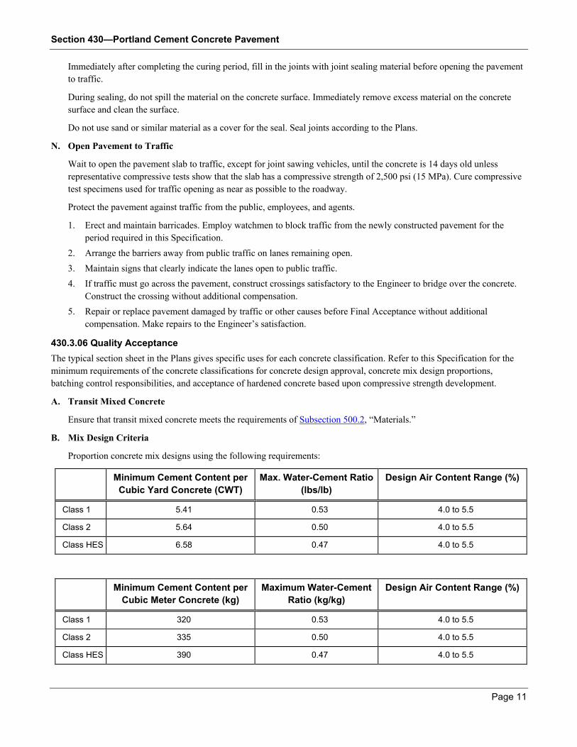
B. Mix Design Criteria
Proportion concrete mix designs using the following requirements:
Minimum Cement Content per
Cubic Yard Concrete (CWT)
Max. Water-Cement Ratio
(lbs/lb)
Design Air Content Range (%)
Class 1 5.41 0.53 4.0 to 5.5
Class 2 5.64 0.50 4.0 to 5.5
Class HES 6.58 0.47 4.0 to 5.5
Minimum Cement Content per
Cubic Meter Concrete (kg)
Maximum Water-Cement
Ratio (kg/kg)
Design Air Content Range (%)
Class 1 320 0.53 4.0 to 5.5
Class 2 335 0.50 4.0 to 5.5
Class HES 390 0.47 4.0 to 5.5
Section 430—Portland Cement Concrete Pavement
Page 12
Produce evidence that the mix design proportions for Class 1 and 2 concrete have strength development potential for 24
hours plus or minus 15 minutes and at 28 days as specified in Subsection 430.3.06.C, “Approval of Mix Design
Proportions”.
C. Approval of Mix Design Proportions
The Department will approve each proposed combination of materials and mix designs based on the use of approved
materials, compliance with Subsection 430.3.06.B, “Mix Design Criteria,” and the following:
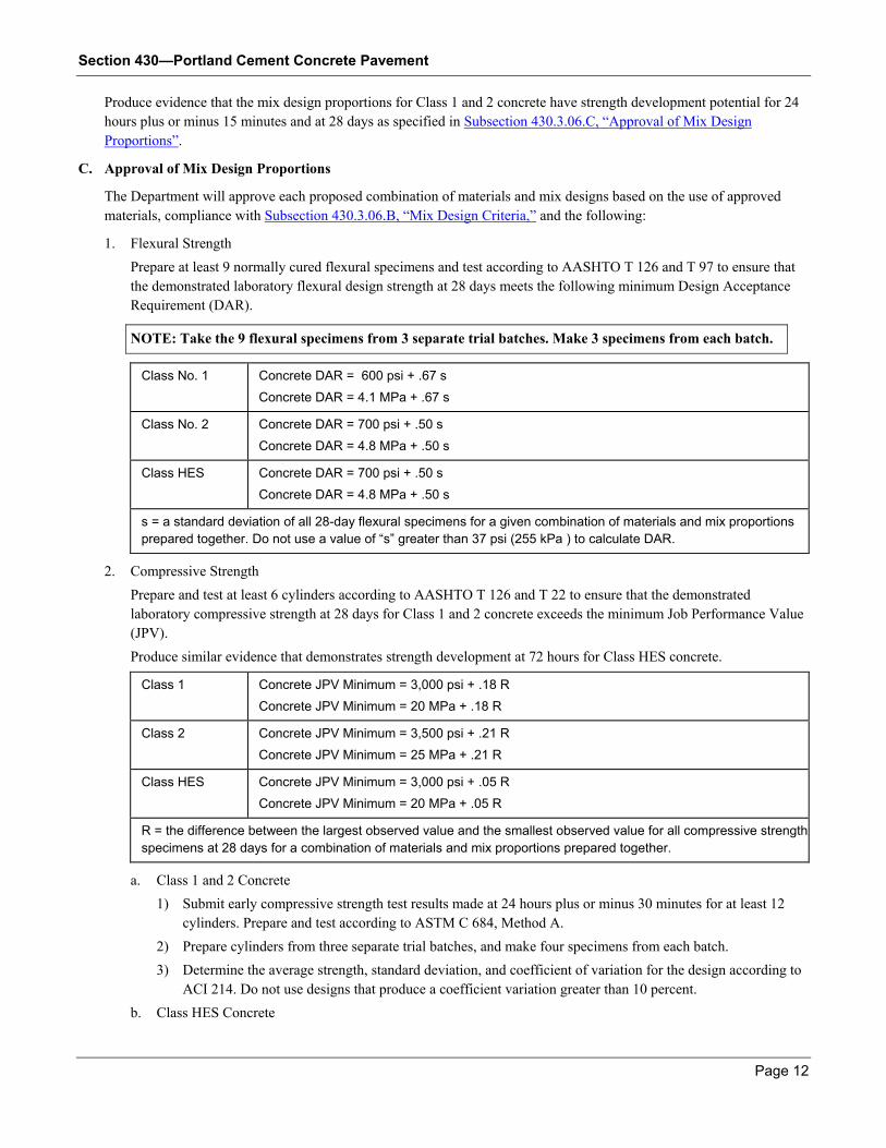
1. Flexural Strength
Prepare at least 9 normally cured flexural specimens and test according to AASHTO T 126 and T 97 to ensure that
the demonstrated laboratory flexural design strength at 28 days meets the following minimum Design Acceptance
Requirement (DAR).
NOTE: Take the 9 flexural specimens from 3 separate trial batches. Make 3 specimens from each batch.
Class No. 1 Concrete DAR = 600 psi + .67 s
Concrete DAR = 4.1 MPa + .67 s
Class No. 2 Concrete DAR = 700 psi + .50 s
Concrete DAR = 4.8 MPa + .50 s
Class HES Concrete DAR = 700 psi + .50 s
Concrete DAR = 4.8 MPa + .50 s
s = a standard deviation of all 28-day flexural specimens for a given combination of materials and mix proportions
prepared together. Do not use a value of “s” greater than 37 psi (255 kPa ) to calculate DAR.
2. Compressive Strength
Prepare and test at least 6 cylinders according to AASHTO T 126 and T 22 to ensure that the demonstrated
laboratory compressive strength at 28 days for Class 1 and 2 concrete exceeds the minimum Job Performance Value
(JPV).
Produce similar evidence that demonstrates strength development at 72 hours for Class HES concrete.
Class 1 Concrete JPV Minimum = 3,000 psi + .18 R
Concrete JPV Minimum = 20 MPa + .18 R
Class 2 Concrete JPV Minimum = 3,500 psi + .21 R
Concrete JPV Minimum = 25 MPa + .21 R
Class HES Concrete JPV Minimum = 3,000 psi + .05 R
Concrete JPV Minimum = 20 MPa + .05 R
R = the difference between the largest observed value and the smallest observed value for all compressive strength
specimens at 28 days for a combination of materials and mix proportions prepared together.
a. Class 1 and 2 Concrete
1) Submit early compressive strength test results made at 24 hours plus or minus 30 minutes for at least 12
cylinders. Prepare and test according to ASTM C 684, Method A.
2) Prepare cylinders from three separate trial batches, and make four specimens from each batch.
3) Determine the average strength, standard deviation, and coefficient of variation for the design according to
ACI 214. Do not use designs that produce a coefficient variation greater than 10 percent.
b. Class HES Concrete
Section 430—Portland Cement Concrete Pavement
Page 13
Submit evidence that designs proposed for use as Class HES concrete have compressive strength development
potential at 72 hours of 3,000 psi (20 MPa) plus .05 R.
D. Field Adjustments on Concrete Mixes
Determine the aggregate surface moisture and apply free moisture corrections to the approved mix design. The Engineer
will verify that the corrections are made properly.
Adjust the approved proportions of the fine and coarse aggregate and water as desired, provided:
1. The cement factor is not decreased.
2. The water-cement ratio is not increased.
3. Adjustments produce concrete proportions according to this Specification.
4. The Engineer is notified before use.
E. Concrete Mix Tolerances
Keep concrete consistency and air content to vary within the following limits:
1. Consistency
Immediately before placement, use GDT 27 to determine concrete slump. Do not use concrete for Portland cement
concrete pavement with a slump value greater than 2.5 in (65 mm).
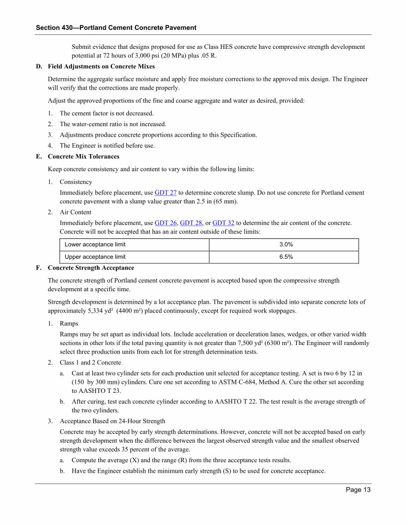
2. Air Content
Immediately before placement, use GDT 26, GDT 28, or GDT 32 to determine the air content of the concrete.
Concrete will not be accepted that has an air content outside of these limits:
Lower acceptance limit 3.0%
Upper acceptance limit 6.5%
F. Concrete Strength Acceptance
The concrete strength of Portland cement concrete pavement is accepted based upon the compressive strength
development at a specific time.
Strength development is determined by a lot acceptance plan. The pavement is subdivided into separate concrete lots of
approximately 5,334 yd² (4400 m²) placed continuously, except for required work stoppages.
1. Ramps
Ramps may be set apart as individual lots. Include acceleration or deceleration lanes, wedges, or other varied width
sections in other lots if the total paving quantity is not greater than 7,500 yd² (6300 m²). The Engineer will randomly
select three production units from each lot for strength determination tests.
2. Class 1 and 2 Concrete
a. Cast at least two cylinder sets for each production unit selected for acceptance testing. A set is two 6 by 12 in
(150 by 300 mm) cylinders. Cure one set according to ASTM C-684, Method A. Cure the other set according
to AASHTO T 23.
b. After curing, test each concrete cylinder according to AASHTO T 22. The test result is the average strength of
the two cylinders.
3. Acceptance Based on 24-Hour Strength
Concrete may be accepted by early strength determinations. However, concrete will not be accepted based on early
strength development when the difference between the largest observed strength value and the smallest observed
strength value exceeds 35 percent of the average.
a. Compute the average (X) and the range (R) from the three acceptance tests results.
b. Have the Engineer establish the minimum early strength (S) to be used for concrete acceptance.
Section 430—Portland Cement Concrete Pavement
Page 14
The minimum early acceptance strength is the average strength at 24 hours plus or minus 30 minutes of the
laboratory design less 1.5 times the standard deviation of the laboratory design.
c. If the average (X) of the three lot acceptance tests equal or exceed the value (S), the lot will be accepted at the
full contract price, and 28 day cylinders for this lot can be discarded.
d. If the average of the three lot acceptance tests fails to meet the acceptance limit, the Engineer will contact the
Contractor immediately. The Contractor may immediately remove the concrete in the lot or leave it in place
pending acceptance or rejection from the 28-day strength test results.
4. Acceptance Based on 28-Day Strength Tests
When a lot is potentially defective based on the early strength determinations and the Contractor leaves the lot in
place to be judged by the 28-day strength tests results, retain and cure all 3 sets of 28-day cylinders.
a. If the average 28-day strength of the lot does not meet the lower acceptance limit for a 0.70 pay factor, the
Engineer may either:
Order removal of the concrete in the lot
Apply a pay factor of 0.50 for the lot
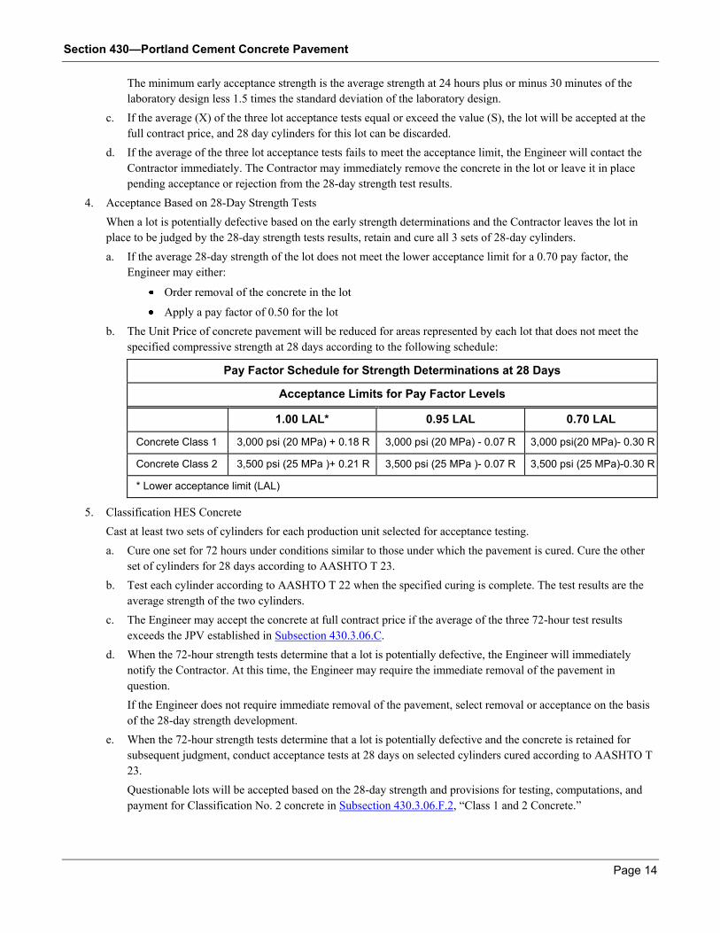
b. The Unit Price of concrete pavement will be reduced for areas represented by each lot that does not meet the
specified compressive strength at 28 days according to the following schedule:
Pay Factor Schedule for Strength Determinations at 28 Days
Acceptance Limits for Pay Factor Levels
1.00 LAL* 0.95 LAL 0.70 LAL
Concrete Class 1 3,000 psi (20 MPa) + 0.18 R 3,000 psi (20 MPa) - 0.07 R 3,000 psi(20 MPa)- 0.30 R
Concrete Class 2 3,500 psi (25 MPa )+ 0.21 R 3,500 psi (25 MPa )- 0.07 R 3,500 psi (25 MPa)-0.30 R
* Lower acceptance limit (LAL)
5. Classification HES Concrete
Cast at least two sets of cylinders for each production unit selected for acceptance testing.
a. Cure one set for 72 hours under conditions similar to those under which the pavement is cured. Cure the other
set of cylinders for 28 days according to AASHTO T 23.
b. Test each cylinder according to AASHTO T 22 when the specified curing is complete. The test results are the
average strength of the two cylinders.
c. The Engineer may accept the concrete at full contract price if the average of the three 72-hour test results
exceeds the JPV established in Subsection 430.3.06.C.
d. When the 72-hour strength tests determine that a lot is potentially defective, the Engineer will immediately
notify the Contractor. At this time, the Engineer may require the immediate removal of the pavement in
question.
If the Engineer does not require immediate removal of the pavement, select removal or acceptance on the basis
of the 28-day strength development.
e. When the 72-hour strength tests determine that a lot is potentially defective and the concrete is retained for
subsequent judgment, conduct acceptance tests at 28 days on selected cylinders cured according to AASHTO T
23.
Questionable lots will be accepted based on the 28-day strength and provisions for testing, computations, and
payment for Classification No. 2 concrete in Subsection 430.3.06.F.2, “Class 1 and 2 Concrete.”
Section 430—Portland Cement Concrete Pavement
Page 15
G. Smoothness
Pavement smoothness will be accepted only after the Engineer determines that the work was performed according to this
and other Specifications. The completed pavement, including corrective work, must meet the applicable profile index
value requirements.
Perform smoothness testing as follows:
1. Ensure that the mainline riding surface produces a profile index value no greater than 7 in/mile (100 mm/ km) on
each travel lane. Conduct tests according to GDT 78.
2. Determine a profile index value for each tracing for each 0.25 mile (0.5 km) segment. Correct individual bumps or
depressions that exceed the blanking band by more than 0.2 in (5 mm) at no additional expense to the Department.
3. If a paving operation exceeds a profile index value of 7 in/mile (100 mm/km) per lane for any segment, suspend the
paving operation and take corrective action approved by the Engineer.
4. Use GDT 78 to test ramps and acceleration and deceleration lanes to attain an average profile index value no greater
than 12 in/mile (200 mm/km) by Rainhart Profilograph for the entire section length. Correct individual bumps or
depressions that exceed 0.2 in (5 mm) from the blanking band at no additional expense to the Department.
5. Take pavement profiles that are 4 ft (1.2 m) away from and parallel to the new pavement edges on pavements
greater than 16 ft(4.8 m) wide and up to 24 ft (7.2 m) wide.
Test pavement 6 to 16 ft (1.8 to 4.8 m) wide parallel to and at the center line of the pavement section.
6. Begin the 0.25 mile (0.5 km) record segments at the first day’s placement and continue until Project completion,
except as noted in this Specification.
7. Combine pavement sections less than 700 ft (200 m) long that approach a bridge. Use the previous 0.25 mile (0.5
km) segment to determine the profile index.
Calculate as a separate record segment 700 ft (200 m) sections or greater that approach a bridge. This exception
applies also to sections at Project limits.
8. Determine a separate profile index value using GDT 78 for the 100 ft (30 m) of roadway approaching each end of a
bridge up to and including the joint with the approach slab.
Average the profile index from the right and left wheelpaths for each 100 ft (30 m) segment for each lane for each
approach. The average profile index value shall not exceed 30 in/mile (500 mm/km).
9. Before paving farther, perform and evaluate profiles from the first day’s placement.
a. After completing and evaluating this test run, adjust equipment as required by the Engineer to improve
smoothness before paving continues.
b. Complete the report form furnished by the Engineer and attach to the profilograph tracings of each day. Include
the following information in each trace:
Project number
Beginning and ending station numbers
500 ft (150 m) paving stations
Traffic direction
Lane number
Date paved and tested
Construction joint locations
Have the certified profilograph operator obtain and evaluate the traces and submit the evaluation to the Engineer.
Provide results no later than the end of the second work day following placement.
Section 430—Portland Cement Concrete Pavement
Page 16
10. For mainline pavement, correct 0.25 mile (0.5 km) segments not meeting the profile index requirement using one of
these methods:
a. Grind the entire lane surface of the 0.25 mile (0.5 km) segment to a profile index value less than 7 in/mile (100
mm/km). Use equipment that meets requirements in Section 431.
b. Grind roughness in small segment areas no more than 50 ft (15 m) of full lane width to produce a profile index
value no greater than 7 in/mile (100 mm/km).
If more than 50 ft (15 m) of grinding is required, grind the complete 0.25 mile (0.5 km) segment according to
Method a, above.
11. Correct ramps and acceleration and deceleration lanes that do not meet the profile index requirement to a profile
index no greater than 12 in/mile (200 mm/km). Prevent individual bumps from exceeding 0.2 in (5 mm) from the
blanking band. Use equipment specified in Section 431.
12. Correct 100 ft (30 m) bridge approach sections that do not meet the profile index requirement.
a. Grind according to Section 431.
b. If appropriate, use a bump grinder to correct bumps with a baseline of 5 ft (1.5 m) or less.
c. Grind the full lane width even when grinding including individual bumps.
d. Retest pavement segments containing corrective slab replacements for Final Acceptance.
13. Correct segments that do not meet the profile index criteria of this Specification at no additional expense to the
Department. Retest segments after correction with the Rainhart Profilograph.
14. Notify the Engineer before profile testing. The Engineer will verify the results by randomly selecting a minimum of
1 out of every 10 consecutive record segment profiles to compute the profile index and to compare with Contractor
results.
The Engineer may conduct profilograph tests at any time to verify Contractor results. The Department may test
record segments if the Engineer determines that the Contractor test results are inaccurate. See Subsection 430.5.01,
“Adjustments.”
H. Thickness
The Engineer shall determine the pavement thickness using average core measurements tested according to GDT 31.
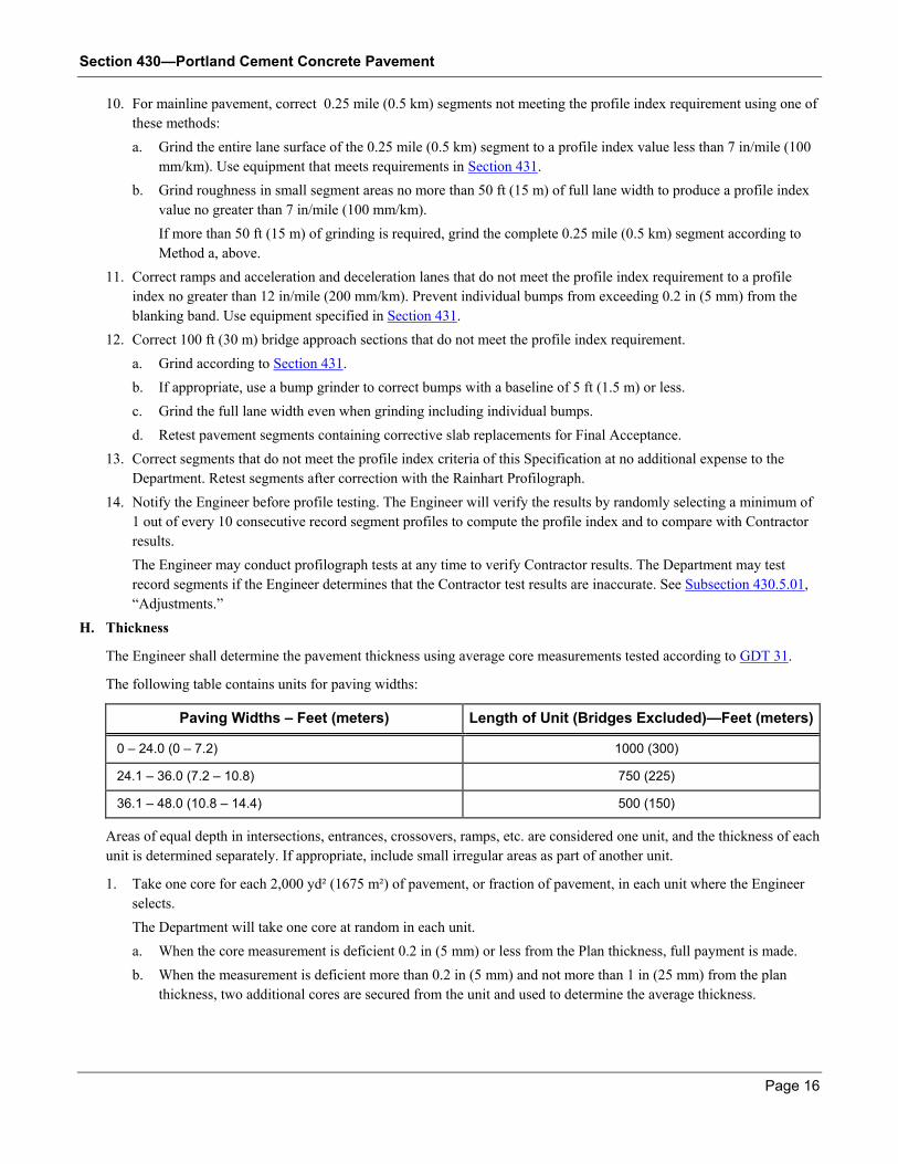
The following table contains units for paving widths:
Paving Widths – Feet (meters) Length of Unit (Bridges Excluded)—Feet (meters)
0 – 24.0 (0 – 7.2) 1000 (300)
24.1 – 36.0 (7.2 – 10.8) 750 (225)
36.1 – 48.0 (10.8 – 14.4) 500 (150)
Areas of equal depth in intersections, entrances, crossovers, ramps, etc. are considered one unit, and the thickness of each
unit is determined separately. If appropriate, include small irregular areas as part of another unit.
1. Take one core for each 2,000 yd² (1675 m²) of pavement, or fraction of pavement, in each unit where the Engineer
selects.
The Department will take one core at random in each unit.
a. When the core measurement is deficient 0.2 in (5 mm) or less from the Plan thickness, full payment is made.
b. When the measurement is deficient more than 0.2 in (5 mm) and not more than 1 in (25 mm) from the plan
thickness, two additional cores are secured from the unit and used to determine the average thickness.
Section 430—Portland Cement Concrete Pavement
Page 17
c. A random selection process determines where to secure additional cores. However, do not secure cores within
50 ft (15 m) of other thickness measurement cores. The adjusted Unit Price in Subsection 430.5.01.A,
“Concrete Pavement Thickness Deficiency” is used to determine payment for the unit.
2. Consider pavement more than 0.2 in (5 mm) thicker than the specified thickness to be the specified thickness plus
0.2 in (5 mm). Measurements more than 1 in (25 mm) less than the specified thickness are not included in the
average.
3. When the core measurement is at least 1 in (25 mm) less than the specified thickness:
a. Determine the pavement thickness in the affected location by taking additional cores at no less than 10 ft (3 m)
intervals parallel to the center line in each direction.
b. Continue until a core is found that is not deficient by more than 1 in (25 mm).
c. Have the Engineer evaluate areas more than 1 in (25 mm) deficient in thickness. Remove deficient areas and
replace with concrete pavement of the thickness shown on the Plans, if the Engineer requires.
Exploratory cores for deficient thickness are not used in averages for adjusted Unit Price.
430.3.07 Contractor Warranty and Maintenance
General Provisions 101 through 150.
430.4 Measurement
The area that will be paid for under this Item is the number of square yards (meters) of concrete pavement accepted as
measured complete in place. The pavement width measured is shown on the typical cross section of the Plans, including
additional widening as required or widening directed in writing by the Engineer.
The length is measured along the pavement surface.
Work is accepted lot-to-lot according to Section 106 and this Specification.
430.4.01 Limits
General Provisions 101 through 150.
430.5 Payment
Concrete pavement completed and accepted that meets the Specification requirements will be paid for at the full Contract
Unit Price per square yard (meter).
Payment for other accepted concrete pavement will be based on an adjusted Unit Price per square yard (meter). This price
will be adjusted for payment for concrete pavement accepted but deficient in depth or compressive strength at 28 days. Price
adjustments are specified in Subsection 430.5.01, “Adjustments.”
No additional payment over the Contract Unit Price will be made for pavement units with an average thickness greater than
on the Plans. No additional payment over the Contract Unit Price will be made for a lot of concrete that develops more
strength at 28 days than the compressive strength established in Subsection 430.3.06.F, “Concrete Strength Acceptance.”
Payment is full compensation for furnishing and placing materials, reinforcements, dowel and joint materials, supplies, and
incidentals to complete the work.
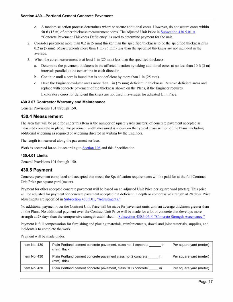
Payment will be made under:
Item No. 430 Plain Portland cement concrete pavement, class no. 1 concrete ______ in
(mm) thick
Per square yard (meter)
Item No. 430 Plain Portland cement concrete pavement class no. 2 concrete _____ in
(mm) thick
Per square yard (meter)
Item No. 430 Plain Portland cement concrete pavement, class HES concrete _____ in Per square yard (meter)
Section 430—Portland Cement Concrete Pavement
Page 18
(mm) thick
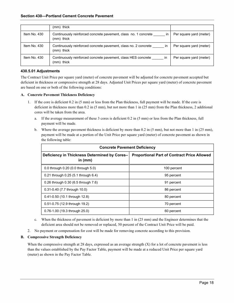
Item No. 430 Continuously reinforced concrete pavement, class no. 1 concrete ______ in
(mm) thick
Per square yard (meter)
Item No. 430 Continuously reinforced concrete pavement, class no. 2 concrete ______ in
(mm) thick
Per square yard (meter)
Item No. 430 Continuously reinforced concrete pavement, class HES concrete ______ in
(mm) thick
Per square yard (meter)
430.5.01 Adjustments
The Contract Unit Price per square yard (meter) of concrete pavement will be adjusted for concrete pavement accepted but
deficient in thickness or compressive strength at 28 days. Adjusted Unit Prices per square yard (meter) of concrete pavement
are based on one or both of the following conditions:
A. Concrete Pavement Thickness Deficiency
1. If the core is deficient 0.2 in (5 mm) or less from the Plan thickness, full payment will be made. If the core is
deficient in thickness more than 0.2 in (5 mm), but not more than 1 in (25 mm) from the Plan thickness, 2 additional
cores will be taken from the area.
a. If the average measurement of these 3 cores is deficient 0.2 in (5 mm) or less from the Plan thickness, full
payment will be made.
b. Where the average pavement thickness is deficient by more than 0.2 in (5 mm), but not more than 1 in (25 mm),
payment will be made at a portion of the Unit Price per square yard (meter) of concrete pavement as shown in
the following table:
Concrete Pavement Deficiency
Deficiency in Thickness Determined by Cores–
in (mm)
Proportional Part of Contract Price Allowed
0.0 through 0.20 (0.0 through 5.0) 100 percent
0.21 through 0.25 (5.1 through 6.4) 95 percent
0.26 through 0.30 (6.5 through 7.6) 91 percent
0.31-0.40 (7.7 through 10.0) 86 percent
0.41-0.50 (10.1 through 12.8) 80 percent
0.51-0.75 (12.9 through 19.2) 70 percent
0.76-1.00 (19.3 through 25.0) 60 percent
c. When the thickness of pavement is deficient by more than 1 in (25 mm) and the Engineer determines that the
deficient area should not be removed or replaced, 50 percent of the Contract Unit Price will be paid.
2. No payment or compensation for cost will be made for removing concrete according to this provision.
B. Compressive Strength Deficiency
When the compressive strength at 28 days, expressed as an average strength (X) for a lot of concrete pavement is less
than the values established by the Pay Factor Table, payment will be made at a reduced Unit Price per square yard
(meter) as shown in the Pay Factor Table.
Section 430—Portland Cement Concrete Pavement
Page 19
C. Combined Deficiencies
When a pavement section is deficient in thickness and compressive strength, the Contract Unit Price will be adjusted by
the total reduction from applying the percentages in Subsections 430.5.01.A and Subsection 430.5.01.B, above.
For combined deficiencies of 50 percent or more, the Engineer may leave the pavement in place at the combined
payment reduction or order the deficient areas removed and replaced at no additional cost to the Department.
If the Engineer orders removal of the pavement, payment will not be made for the original pavement or removal.
Pavement replaced will be paid for at the appropriate Unit Price.
D. Profilograph Testing
If, based on the Department’s profilograph tests, the Engineer determines that the Contractor profilograph test results are
inaccurate, the Contractor will be charged for profilograph testing at $500 for each trace mile ($250 for each trace
kilometer), with a minimum charge of $500.