SECTION 40 05 15 - Ruby-Collins Construction Atlanta...
100
SECTION 40 05 15 PIPING SUPPORT SYSTEMS PART 1 - GENERAL 1.01 REFERENCES A. The following is a list of standards which may be referenced in this section: 1. American Society of Civil Engineers (ASCE): 7, Minimum Design Loads for Buildings and Other Structures. 2. American Society of Mechanical Engineers (ASME): B31.1, Power Piping. 3. ASTM International (ASTM): a. A123/A123M, Standard Specification for Zine (Hot-Dip Galvanized) Coatings on Iron and Steel Products. b. A653/A653M, Standard Specification for Steel Sheet, Zine Coated (Galvanized) or Zine-Iron Alloy-Coated (Galvanized) by the Hot-Dip Process. 4. International Code Council (ICC): a. International Building Code (IBC). b. International Mechanical Code (IMC). 5. Manufacturers' Standardization Society (MSS): a. SP 58, Pipe Hangers and Supports - Materials, Design and Manufacture. b. SP 69, Pipe Hangers and Supports - Selection and Application. c. SP 89, Pipe Hangers and Supports - Fabrication and Installation Practices. d. SP 127, Bracing for Piping Systems, Seismic-Wind-Dynamic Design, Selection and Application 1.02 DEFINITIONS A. Wetted or Submerged: Submerged, less than 1 foot above liquid surface, below top of channel wall, under cover or slab of channel or tank or in other damp locations. 1.03 SUBMITTALS A. Action Submittals: 1. Catalog information and drawings of piping support system, locating each support, sway brace, seismic brace, hanger, guide, component, and anchor for piping 6 inches and larger. Identify support, hanger, guide and anchor type by catalog number and shop drawing detail number. 2. For piping 4 inches and smaller provide catalog information for each type of support. 40 05 15 - 1 Piping Support Systems Bid Set Tt#200-11740-10003 Teka Tech,Inc.
Transcript of SECTION 40 05 15 - Ruby-Collins Construction Atlanta...

SECTION 40 05 15PIPING SUPPORT SYSTEMS
PART 1 - GENERAL
1.01 REFERENCES
A. The following is a list of standards which may be referenced in this section:
1. American Society of Civil Engineers (ASCE): 7, Minimum Design Loads forBuildings and Other Structures.
2. American Society of Mechanical Engineers (ASME): B31.1, Power Piping.3. ASTM International (ASTM):
a. A123/A123M, Standard Specification for Zine (Hot-Dip Galvanized)Coatings on Iron and Steel Products.
b. A653/A653M, Standard Specification for Steel Sheet, Zine Coated(Galvanized) or Zine-Iron Alloy-Coated (Galvanized) by the Hot-DipProcess.
4. International Code Council (ICC):a. International Building Code (IBC).b. International Mechanical Code (IMC).
5. Manufacturers' Standardization Society (MSS):a. SP 58, Pipe Hangers and Supports - Materials, Design and Manufacture.b. SP 69, Pipe Hangers and Supports - Selection and Application.c. SP 89, Pipe Hangers and Supports - Fabrication and Installation
Practices.d. SP 127, Bracing for Piping Systems, Seismic-Wind-Dynamic Design,
Selection and Application
1.02 DEFINITIONS
A. Wetted or Submerged: Submerged, less than 1 foot above liquid surface, below top ofchannel wall, under cover or slab of channel or tank or in other damp locations.
1.03 SUBMITTALS
A. Action Submittals:
1. Catalog information and drawings of piping support system, locating eachsupport, sway brace, seismic brace, hanger, guide, component, and anchor forpiping 6 inches and larger. Identify support, hanger, guide and anchor type bycatalog number and shop drawing detail number.
2. For piping 4 inches and smaller provide catalog information for each type ofsupport.
40 05 15 - 1Piping Support Systems Bid SetTt#200-11740-10003 Teka Tech,Inc.

3. Submit revisions to support systems resulting from changes in related pipingsystem layout or addition of flexible joints.
B. Information Submittals: Maintenance information on piping support system.
1.04 DESIGN REQUIREMENTS
A. General:
1. Design, size, and locate piping support systems throughout facility, whethershown on the Drawings or not.
2. Piping Smaller than 30 Inches: Supports are shown only where specific typesand locations are required; additional pipe supports may be required inaccordance with this Specification, referenced standards, or the pipe andequipment and manufacturer's recommendations.
3. Piping 30 Inches and Larger: Support systems have been designed for pipingshown.
4. Meet requirements of MSS SP58, MSS SP 69, MSS SP 89, and ASME B31.1.or as modified by this Section.
5. Supports for exposed PVC pipe shall be as set forth below:a. Straight Runs: 5'-0" on-center (maximum)b. Elbows and Bends: Each side of fittingc. Tees: Each side of run and on branch
B. Pipe Support Systems:
1. Pipe support systems shall be designed for gravity and thrust loads imposed byweight of pipes or internal pressures, including weight of fluid in pipes andinsulation.
2. Seismic loads shall be addressed in accordance with governing codes and asshown on Structural General Drawings
3. Wind loads shall be addressed in accordance with governing codes and as shownon Structural General Drawings
4. Maximum support spacing and minimum rod size shall be in accordance withMSS SP-69 Table 3 and Table 4 unless specified otherwise.
C. Anchoring Devices: Design, size, and space support anchoring devices, includinganchor bolts, inserts and other devices used to anchor support, to withstand shear andpullout loads imposed by loading and spacing of each particular support.
D. Vertical Sway Bracing: 10-foot maximum centers or as shown on the Drawings.
40 05 15 - 2Piping Support Systems Bid SetTt#200-11740-10003 Teka Tech,Inc.
PART 2 - PRODUCTS
2.01 GENERAL
A. When specified items are not available, fabricate pipe supports of correct material andto general configuration indicated.
B. Special support and hanger details may be required for cases where standard catalogsupports are inapplicable.
2.02 HANGERS
A. Clevis: MSS SP-58 and SP-69, Type 1.
1. Anvil; Figure 260, sizes ½ inch through 30 inches.2. For Insulated Pipe: Anvil; Figure 260 with insulated saddle system (ISS) sizes ½
inch through 16 inches.3. B-Line; Figure B3100, sizes ½ inch through 30 inches.4. Or equal.
2.03 SADDLE SUPPORTS
A. Saddle Type: Schedule 40 pipe stanchion, saddle, and anchoring flange.
1. Nonadjustable Saddle: MSS SP 58 and MSS SP 69, Type 37 with U-bolt.a. Anvil; Figure 259, sizes 4 inches through 36 inches with Figure 63D
base.b. B-Line; Figure B3090, sizes ¾ inches through 36 inches with B3088
base.c. Or equal.
2. Adjustable Saddle: MSS SP 58 MSS SP 69, Type 38 without clamp.a. Anvil; Figure 264, sizes 2-½ inches through 36 inches with Figure 63T
base.b. B-Line; Figure B3093, sizes 1 inch through 36 inches with Figure
B3088T base.c. Or equal.
B. Elbow and Flange Supports:
1. Elbow with Adjustable Stanchion:a. Sizes 2 inches through 18 inches.
1) Anvil; Figure 62C base.2) Or equal.
40 05 15 - 3Piping Support Systems Bid SetTt#200-11740-10003 Teka Tech,Inc.
2. Elbow with Nonadjustable Stanchion:a. Sizes 2-½ inches through 42 inches.
1) Anvil; Figure 63C base.2) Or equal.
3. Flange Support with Adjustable Base:a. Sizes 4 inches through 24 inches.
1) B-Line; B3094, with Figure B3088T base.2) Standon; Model S89.3) Or equal.
2.04 WALL BRACKETS AND SUPPORTS
A. Welded Steel Wall Bracket: MSS SP 58 and MSS SP 69, Type 33 (heavy-duty),galvanized.
1. Anvil; Figure 199, 3,000-pound rating.2. B-Line; Figure B3067, 3,000-pound rating.3. Or equal.
B. Offset Pipe Clamp:
1. Anvil; Figure 103, sizes ¾ inch through 8 inches.2. B-Line; Figure 3148, sizes ½ inch through 12 inches.3. Above models set forth dimension and load carrying requirements. Material
requirements are shown on the Drawings.4. Or equal.
C. Channel Type:
1. Unistrut.2. Anvil; Power-Strut.3. B-Line; Strut System.4. Aickinstrut (FRP).5. Or equal.
2.05 PIPE CLAMPS
A. Riser Clamp: MSS SP 58 and MSS SP 69, Type 8.
1. Anvil; Figure 261, sizes ¾ inch through 24 inches.2. B-Line; Figure B3373, sizes ½ inch through 30 inches.3. Or equal.
40 05 15 - 4Piping Support Systems Bid SetTt#200-11740-10003 Teka Tech,Inc.

2.06 CHANNEL TYPE SUPPORT SYSTEMS
A. Channel Size: 12-gauge, 1-5/s inch side minimum steel, or 1-½ inch side, minimumFRP.
B. Members and Connections: Design for load using one-half of manufacturer's allowableloads.
C. Fasteners: Vinyl ester fiber, polyurethane base composite nuts and bolts, or encapsulatedsteel fasteners.
D. Manufacturers and Products:
1. B-Line; Strut Systems.2. Unistrut.3. Anvil; Power-Strut.4. Aickinstrut (FRP System).5. Or equal.
2.07 SEISMIC RESTRAINTS
A. Solid pipe bracing attachment to pipe clevis with clevis cross brace and angle rodreinforcement.
B. Manufacturer: Mason Industries or equal.
2.08 ACCESSORIES
A. Insulation Shields:
1. Type: Galvanized steel or stainless steel, MSS SP 58 and MSS SP 69, Type 40.2. Manufacturers and Products:
a. Anvil; Figure 167, sizes ½ inch through 24 inches.b. B-Line; Figure B3151, sizes ½ inch through 24 inches.c. Or equal.
B. Welding Insulation Saddles:
1. Type: MSS SP 59 and MSS SP 69, Type 39.2. Manufacturers and Products:
a. Anvil; Figure 160, sizes 1 inch through 36 inches.b. B-Line; Figure Series B3160, sizes ½ inch through 24 inches.c. Or equal.
40 05 15 - 5Piping Support Systems Bid SetTt#200-11740-10003 Teka Tech,Inc.
C. Plastic Pipe Support Channel:
1. Type: Continuous support for plastic pipe to increase support spacing.2. Manufacturer and Product: B-Line; Figure Series B3106V, sizes ½ inch through
4 inches with Figure B3106 Vee bottom hangers; or equal.
D. Hanger Rods, Clevises, Nuts, Sockets, and Turnbuckles: In accordance with MSS SP58.
E. Attachments:
1. I-Beam Clamp: Concentric loading type, MSS SP 58 and MSS SP 69, Type 21,Type 28, Type 29 or Type 30 which engage both sides of the flange.
2. Concrete Insert: MSS SP 58 and MSS SP 69, Type 22.a. Anvil; Figure 66.b. B-Line; Figure B3083.c. Or equal.
3. Welded Beam Attachment: MSS SP 58 and MSS SP 69, Type 22.a. Anvil; Figure 66.b. B-Line; Figure B3083.c. Or equal.
4. U-Channel Concrete Inserts: As specified in Section 05 50 00, MetalFabrications.
5. Concrete Attachment Plates:a. Anvil; Figure 47, Figure 49 or Figure 52.b. B-Line; Figure B3084, Figure B3085, or Figure B3086.c. Or equal.
2.09 INTERMEDIATE PIPE GUIDES
A. Type: Hold down pipe guide.
1. Manufacturer and Product: B-Line; Figure B3552, 1-½ inches through 30 inches;or equal.
B. Type: U-bolts with double nuts to provide nominal ¹/s inch to ¼ inch clearance aroundpipe. MSS SP 58 and MSS SP 69, Type 24.
1. Anvil; Figure 137 and Figure 137S.2. B-Line; Figure B3188 and Figure B3188NS.3. Or equal.
40 05 15 - 6Piping Support Systems Bid SetTt#200-11740-10003 Teka Tech,Inc.

2.10 PIPE ALIGNMENT GUIDES
A. Type: Spider.
B. Manufacturers and Products:
1. Anvil; Figure 255, sizes ½ inch through 24 inches.2. B-Line; Figure B3281 through B3287, sizes: ½ inch through 24 inches.3. Or equal.
2.11 PIPE ANCHORS
A. Type: Anchor chair with U-bolt strap.
B. Manufacturer and Product: B-Line; Figure 3147A or Figure 3174B; or equal.
2.12 ANCHORING SYSTEMS
A. Size and Material: Sized by equipment manufacturer, ½-inch minimum diameter.
PART 3 EXECUTION
3.01 INSTALLATION
A. General:
1. Install support systems in accordance with MSS SP 69 and MSS SP 89, unlessshown otherwise.
2. Install pipe hanger rods plumb, within 4 degrees of vertical during shut down,start up or operations.
3. Support piping connections to equipment by pipe support and not by equipment.4. Support large or heavy valves, fittings, and appurtenances independently of
connected piping.5. Support no pipe from another pipe.6. Support pipe at change in direction or elevation, adjacent to flexible joints and
couplings, and where shown.7. Do not install pipe supports and hangers in equipment access areas or bridge
crane runs.8. Brace hanging pipes against horizontal movement by both longitudinal and
lateral sway bracing and to reduce movement after startup.9. Install lateral supports for seismic loads at changes in direction.10. Install pipe anchors where required to withstand expansion thrust loads and to
direct and control thermal expansion.
40 05 15 - 7Piping Support Systems Bid SetTt#200-11740-10003 Teka Tech,Inc.

11. Repair mounting surfaces to original condition after attachments are made.
B. Standard Pipe Supports:
1. Horizontal Suspended Piping:a. Single Pipes: Adjustable swivel-ring, split-ring, or clevis hangers.b. Grouped Pipes: Trapeze hanger system.
2. Horizontal Piping Supported from Walls:a. Single Pipes: Wall brackets or clamps attached to wall with anchors.
Clips attached to wall mounted framing also acceptable.b. Stacked Piping: Wall mounted channel systems are acceptable for piping
smaller than 3-inches in diameter.c. Piping clamps that resist axial movement of pipe through support are not
acceptable. Use cast iron hanging rolls supported from wall bracket.3. Horizontal Piping Supported from Floors:
a. Stanchion Type:1) Pedestal type; adjustable with stanchion, saddle, and anchoring
flange.2) Use yoked saddles for piping whose centerline elevation is 18
inches or greater above floor and for exterior installations.3) Providing minimum 1-½inch grout beneath base plate.
b. Floor Mounted Channel Supports:1) Use for piping smaller than 3-inch nominal diameter running
along floors and in trenches at piping elevations lower than canbe accommodated using pedestal type supports.
2) Attach channel framing to floors with base plate on minimum 1-½ inch grout and with anchor bolts.
3) Attach pipe to channel with clips or pipe clamps.c. Concrete Cradles: Use for piping larger than 3 inches along floor and in
trenches at piping elevations lower than can be accommodated usingstanchion type.
4. Insulated Pipe:a. Pipe hanger and support shall be on outside of insulation and shall not be
enclosed within insulation.b. Provide precut 120-degree sections of rigid insulation (minimum length
same as the shield), galvanized steel shields and oversized hangers orinsulated saddle system. Anvil; Figure 260 (ISS).
c. Wall mounted piping clips not acceptable for insulated piping.5. Vertical Pipe:
a. Support with off-set clamps, wall brackets, and base elbow or riserclamps on floor penetrations.
6. Standard Attachments:a. To Concrete Ceilings: U-Channel Concrete Inserts, U-Channel to
Concrete Attachment Plates.b. To Steel Beams: I-beam clamp or welded attachments.
40 05 15 - 8Piping Support Systems Bid SetTt#200-11740-10003 Teka Tech,Inc.

c. To Wooden Beams: Lag screws and angle clips to members not less than2-½ inches thick.
d. To Concrete Walls: Concrete inserts or brackets or clip angles withanchor bolts.
e. To Concrete Beams: U-Channel concrete inserts, or if inserts are notused attach to vertical surface similar to concrete wall. Do not drill intobeam bottom.
f. Existing Walls and Ceilings: Install as specified for new construction,unless shown otherwise.
C. Intermediate and Pipe Alignment Guides:
1. Provide pipe alignment guides (or pipe supports that provide same function) atexpansion joints and loops.
2. Guide piping on each side of expansion joint or loop at 4-pipe and 14-pipediameters from each joint or loop.
3. Install intermediate guides on metal framing support systems not carrying pipeanchor or alignment guide.
D. Accessories:
1. Insulation Shield: Install on insulated piping, oversize rollers and supports.2. Welding Insulation Saddle: Install on insulated steel pipe, oversize rollers and
supports.3. Dielectric Barrier:
a. Provide plastic coated hangers, or isolation tape such as B-Line Iso Pipe,B-Line B1999 Vibra Cushion, or B-Line B3195 Felt Isolators betweenpainted or galvanized carbon steel members and copper or stainless steelpipe or between stainless steel supports and non-stainless steel ferrousmetal piping.
b. Install ¼-inch by 3-inch neoprene rubber wrap between submerged metalpipe and oversized clamps.
3.02 FIELD FINISHING
A. Paint atmospheric exposed surfaces hot-dip galvanized steel components as specified inSection 09 90 00, Painting and Coating.
END OF SECTION
40 05 15 - 9Piping Support Systems Bid SetTt#200-11740-10003 Teka Tech,Inc.


SECTION 40 05 33PIPE HEAT TRACING
PART 1 GENERAL
1.01 REFERENCES
A. The following is a list of standards that may be referenced within thisspecification:
1. Factory Mutual.
2. Institute of Electrical and Electronics Engineers, Inc. (IEEE) 515,Testing, Design, Installation and Maintenance of Electrical ResistanceHeat Tracing for Industrial Applications.
3. National Electrical Manufacturers' Association (NEMA): 250,Enclosures for Electrical Equipment (1000 Volts Maximum).
4. Underwriters Laboratories (UL), Inc.
1.02 SUBMITTALS
A. Action Submittals:
1. Manufacturer's descriptive literature.2. Plastic Pipe Installations: Output adjustment factors for heating tape
for the services indicated.3. Pipe heat loss calculations for each pipe size to be heat traced.
PART 2 PRODUCTS
2.01 SYSTEM DESIGN REQUIREMENTS
A. Design Heating Load:
1. Heating load to be calculated based upon a 50 degree F delta, 20 mphwind if pipes are located outdoors, insulation as specified in Section 4042 13 and pipe as specified in Section 40 27 00, and shall include a 10percent safety factor.
2. Heat loss calculations shall be based on IEEE 515, Equation 1, Page 19.
40 05 33 - 1Pipe Heat Tracing Bid SetTt#200-11740-10003 Teka Tech,Inc.

2.02 ELECTRICAL HEATING TAPE
A. Cable: Self-limiting, parallel circuit construction consisting of continuous innercore of variable resistance conductive heating material between two parallelcopper bus wires. Provide tinned copper braid for PVC, FRP, and stainless steelpipe applications.
B. UL Listing: Listed as self-limiting pipe tracing material for pipe freeze protectionapplication in ordinary conditions.
C. Maximum Maintenance Temperature: 150 degrees F (65 degrees C).
D. Maximum Intermittent Temperature: 185 degrees F (85 degrees C).
E. Service Voltage: As indicated by branch circuits provided for heat tracing on theDrawings.
F. Manufacturers and Products:
1. Raychem; BTV-CR.
2. Thermon; BSX.
3. Nelson; CL1-J1 or L1-J1.
2.03 CONNECTION SYSTEM
A. Rating: NEMA 250, Type 4 and Factory Mutual approved.
B. Operating Monitor Light: Furnish with each circuit power connection kit toindicate when heat tracing is energized.
C. Manufacturers and Products:
1. Power Connection Kita. Raychem; JBS-100.b. Thermon; PCA-1-SR or DP-L.c. Nelson; PLT-BC.
2. Splice Kit:a. Raychem; S-150.b. Thermon; PCS-1-SR.c. Nelson; PLT-BS.
3. Tee Kit:a. Raychem; T-100.b. Thermon; DS-S.c. Nelson; PLT-BY.
40 05 33 - 2Pipe Heat Tracing Bid SetTt#200-11740-10003 Teka Tech,Inc.

4. End Seal Kit:a. Raychem; E-150.b. Thermon; DE-S. c. Nelson; LT-ME.
5. Lighted End Seal Kit:a. Raychem; E-100-L.b. Thermon; DLS.c. Nelson; LT-L.
2.04 SECURING TAPE
A. Plastic Piping Systems:
1. Type: Aluminum foil coated adhesive tape.
2. Manufacturers and Products:a. Raychem; AT-180.b. Thermon AL-20P.c. Nelson; AT-50.
B. Metallic Piping Systems:
1. Type: Glass or polyester cloth pressure sensitive tape.
2. Manufacturers and Products:a. Raychem; GS54 or GT566b. Thermon; PF-1.c. Nelson; GT-6 or GT-60.
2.05 PIPE MOUNTED THERMOSTAT
A. Type: Fixed, nonadjustable, set at 40 degrees F.
B. Sensor: Fluid-filled with 3-foot capillary.
C. Enclosure: Glass-filled nylon, NEMA 250, Type 4X weatherproof with gasketedlid.
D. Switch: SP-ST, UL listed, rated 22 amps, 120 to 240V ac.
E. Manufacturers and Products:
1. Raychem; Digitrace Model AMC-F5.
2. Thermon; E4X-1.
3. Raychem; DigiTrace Model E507S-LS for hazardous areas.
40 05 33 - 3Pipe Heat Tracing Bid SetTt#200-11740-10003 Teka Tech,Inc.

4. Thermon; E7-25325 for hazardous areas.
2.06 AMBIENT THERMOSTAT
A. Type: Adjustable setting (15 to 140 degrees F).
B. Sensor: Fluid-filled probe.
C. Enclosure: Epoxy-coated NEMA 250, Type 4X aluminum enclosure withexposed hardware of stainless steel.
D. Switch: SP-DT, UL or FM listed, rated 22 amps, 125 to 250V ac.
E. Manufacturers and Products:
1. Raychem; DigiTrace Model AMC-1A.
2. Thermon; B4X-15140.
3. Raychem; DigiTrace Model AMC-1H for hazardous areas.
4. Thermon; B7-15140 for hazardous areas.
PART 3 EXECUTION
3.01 INSTALLATION
A. General:
1. Install in accordance with the manufacturer's instructions andrecommended practices.
2. Provide insulation conforming to Section 40 42 13 over all pipe with heattracing. Insulation shall be "Type 1" with "Type F3 Finish" as defined inSection 40 42 13.
3. Ground metallic structures or materials used for support of heating cableor on which it is installed in accordance with applicable codes.
4. Wiring between power connection points of heat tracing cable branchlines shall be provided by heat tracing system supplier.
5. Provide end of circuit pilot lights on heat tracing circuits for buriedpipmg.
40 05 33 - 4Pipe Heat Tracing Bid SetTt#200-11740-10003 Teka Tech,Inc.

B. Electrical Heating Tape:
1. Determine required length of electrical heating tape by considering lengthof circuit, number and type of fittings and fixtures, design heating load,and heating tape output.
2. Where design heating load exceeds heating tape capacity, install byspiraling.
3. Derate heating tape capacity when installed on plastic piping.
4. Install on services as follows:a. All chemical lines exposed outdoors.b. All water lines 6-inch exposed outdoors including sample and
process lines.c. Sodium Hydroxide lines exposed outdoors or in manholes or
vaults.
5. Install additional heating tape at bolted flanges, valves, pipe supports, andother fittings and fixtures as recommended by supplier, but not less thanthe following:
Item Heating Tape Length(min. feet)
Bolted flanges (per pair) Two times pipe diameterValves Four times valve lengthPipe hanger or support penetrating Three times pipe diameterinsulation
C. Heat Tracing Circuits: Limit individual lengths of heat tracing circuits such thatmaximum single circuit capacity is 20 amps when starting the circuit at 0 degreesF. Provide multiple 20-amp circuits as required at individual heat tracinglocations.
D. Thermostats:
1. Install in accordance with manufacturer's instructions and as approved byEngineer.
2. For each group of heat traced circuit, install one ambient thermostat.
3.02 FIELD QUALITY CONTROL
A. Test each circuit with 500-volt insulation tester between circuit and ground withneutrals isolated from ground.
40 05 33 - 5Pipe Heat Tracing Bid SetTt#200-11740-10003 Teka Tech,Inc.
1. Insulation Resistance: Minimum 1,000 megohms per 1,000 feet.
3.03 HEAT TRACING SCHEDULE
A. Provide heat tracing with appropriate insulation and finish at the followinglocations (exterior above grade piping only).
1. 2" PAC Potable Water Supply Line (Sheet D-0501)2. 2" PAC Slurry/Solution Feed Line (Sheet D-0501)3. 2" Potable Water Line on West Side of Flocculation Basin Influent Channel
for Sludge Line Flushing Water Supply (Sheet D-2102)4. 2" Raw Water Sample Pump Supply Line Upstream of 30" Raw Water Flow
Meter (Sheet D-2102)5. Chemical Feed Piping and Tubing (4 lines, various sizes) at the Raw Water
Static Mixer (Sheet D-2102)6. 1 ½" Polymer Feed Piping and Tubing Downstream of the Raw Water Static
Mixer (Sheet D-2102)7. 2" Raw Water Sample Pump Supply Line Downstream of the Static Mixer8. 2" Potable Water Supply Lines (2 pipes) for Chemical Piping Flushing Water
Located at the North End of the Corridor East of the Flocculation Basins(Sheet D-2102)
9. Chemical Feed Piping at West Side of Filter Influent Channel (Sheet D -2107)
10. Water Supply Lines (3 pipes) for Exterior Emergency Eyewash/Shower Unitson East Side of Chemical Storage Areas (Sheet D-2109)
11. Chemical Feed Piping (12 lines) on North and East Sides of the ChemicalStorage Areas (Sheet D-2109)
12. 2" Raw Water Sample Pump Supply Lines (2 pipes) on the North Side of thePolymer Feed Room (Sheet D-2109)
13. All Above Grade Exposed Fluoride Piping with the Fluoride Storage & FeedArea (Sheet D-2109)
14. 2" Potable Water Supply Line on the East Side of the GAC ContactorStructure (Sheet D-3101)
15. Sample Pump Suction & Discharge Lines (various sizes) Within and Outsideof Sample Pump Vault at Southwest Corner of Disinfectant Contact Basin(Sheet D-4103)
16. 1" Potable Water Sample Line at Northeast Corner of Finished Water PumpRoom (Sheet D-4103)
17. Pressure/Level Transmitter Piping at Elevated Storage Tank (Sheet D-7104)18. 1" Sample Water Line at east side of Blower Room (Sheet D-2108)
END OF SECTION
40 05 33 - 6Pipe Heat Tracing Bid SetTt#200-11740-10003 Teka Tech,Inc.
SECTION 40 27 00PROCESS PIPING, GENERAL
PART 1 GENERAL
1.01 REFERENCES
A. The following is a list of standards which may be referenced in this section and anysupplemental Data Sheets:
1. Air Force: A-A-58092, Tape Antiseize, Polytetrafluorethylene.2. American Association of State Highway and Transportation Officials (AASHTO):
HB-17, Standard Specifications for Highway Bridges.3. American Petroleum Institute (API): SPEC 5L, Specification for Line Pipe.4. American Society of Mechanical Engineers (ASME):
a. Boiler and Pressure Vessel Code, Section VIII, Rules for Construction ofPressure Vessels.
b. Boiler and Pressure Vessel Code, Section IX, Qualification Standard forWelding and Brazing Procedures, Welders, Brazers and Welding and BrazingOperators.
c. B.1.20.1, Pipe Threads, General Purpose (Inch).d. B16.1, Gray Iron Pipe Flanges and Flanged Fittings (Classes 25, 125, and
250).e. B16.3, Malleable Iron Threaded Fittings Classes 150 and 300.f. B16.5, Pipe Flanges and Flanged Fittings NPS ½ through NPS 24 Metric/Inch
Standard.g. B16.9, Factory-Made Wrought Buttwelding Fittings.h. B16.11, Forged Fittings, Socket-Welding and Threaded.i. B16.15, Cast Bronze Threaded Fittings Classes 125 and 250.j. B16.21, Nonmetallic Flat Gaskets for Pipe Flanges.k. B16.22, Wrought Copper and Copper Alloy Solder Joint Pressure Fittings.1. B16.24, Cast Copper Alloy Pipe Flanges and Flanged Fittings: Class 150,
300,400,600,900, 1500,and 2500.m. B16.25, Butt Welding Ends.n. B16.42, Ductile Iron Pipe Flanges and Flanged Fittings Classes 150 and 300.o. B3 1.1, Power Piping.p. B3 1.3, Process Piping.q. B3 1.9, Building Services Piping.r. B36.10MY Welded and Seamless Wrought Steel Pipe.s. B36.19MY Stainless Steel Pipe.
5. American Society for Nondestructive Testing (ASNT): SNT-TC-1A, PersonnelQualification and Certification in Nondestructive Testing.
40 27 00 - 1Process Piping, General Bid SetTt#200-11740-10003 Teka Tech,Inc.

6. American Water Works Association (AWWA):a. C104/A2 1.4, Cement-Mortar Lining for Ductile-Iron Pipe and Fittings for
Water.b. C105/A21.5, Polyethylene Encasement for Ductile-Iron Pipe Systems.c. C110/A21.10, Ductile-Iron and Gray-Iron Fittings for Water.d. C111/A21.11, Rubber-Gasket Joints for Ductile-Iron Pressure Pipe and
Fittings.e. C115/A21.15, Flanged Ductile-Iron Pipe with Ductile-Iron or Gray-Iron
Threaded Flanges.f. C116/A2 1.16, Protective Fusion-Bonded Epoxy Coatings for the Interior and
Exterior Surfaces of Ductile-Iron and Gray-Iron Fittings for Water SupplyService.
g. C151/A21.5 1, Ductile-Iron Pipe, Centrifugally Cast, for Water.h. C153/A2 1.53, Ductile-Iron Compact Fittings for Water Service.i. C207, Steel Pipe Flanges for Waterworks Service, Sizes 4 In. Through 144
In. (100 mm Through 3,600 mm).j. C606, Grooved and Shouldered Joints.
7. American Welding Society (AWS):a. Brazing Handbook.b. A5.8/A8.5M, Specification for Filler Metals for Brazing and Braze Welding.c. QC1, Standard for AWS Certification of Welding Inspectors.
8. ASTM International (ASTM):a. A47/A47M, Standard Specification for Ferritic Malleable Iron Castings.b. A53/A53M, Standard Specification for Pipe, Steel, Black and Hot-Dipped,
Zinc-Coated, Welded and Seamless.c. A105/A105M, Standard Specification for Carbon Steel Forgings for Piping
Applications.d. A106/A106M, Standard Specification for Seamless Carbon Steel Pipe for
High-Temperature Service.e. A126, Standard Specification for Gray Iron Castings for Valves, Flanges, and
Pipe Fittings.f. A135/A135M, Standard Specification for Electric-Resistance-Welded Steel
Pipe.g. A139/A139M, Standard Specification for Electric-Fusion (Arc)-Welded Steel
Pipe (NPS 4 and Over).h. A153/A153M, Standard Specification for Zine Coating (Hot-Dip) on Iron and
Steel Hardware.i. A181/A181M, Standard Specification for Carbon Steel Forgings, for General-
Purpose Piping.j. A182/A182M, Standard Specification for Forged or Rolled Alloy and
Stainless Steel Pipe Flanges, Forged Fittings, and Valves and Parts for High-Temperature Service.
k. A183, Standard Specification for Carbon Steel Track Bolts and Nuts.
40 27 00 - 2Process Piping, General Bid SetTt#200-11740-10003 Teka Tech,Inc.
1. A193/A193M, Standard Specification for Alloy-Steel and Stainless SteelBolting Materials for High Temperature or High Pressure Service and OtherSpecial Purpose Applications.
m. A194/A194M, Standard Specification for Carbon and Alloy Steel Nuts for
Bolts for High Pressure or High Temperature Service, or Both.n. A197/A197M, Standard Specification for Cupola Malleable Iron.o. A21 61A2 16M, Standard Specification for Steel Castings, Carbon, Suitable
for Fusion Welding, for High-Temperature Service.p. A234/A234M, Standard Specification for Piping Fittings of Wrought Carbon
Steel and Alloy Steel for Moderate and High Temperature Service.q. A240/A240M, Standard Specification for Chromium and Chromium-Nickel
Stainless Steel Plate, Sheet, and Strip for Pressure Vessels and for GeneralApplications.
r. A276, Standard Specification for Stainless Steel Bars and Shapes.s. A269, Standard Specification for Seamless and Welded Austenitic Stainless
Steel Tubing for General Service.t. A307, Standard Specification for Carbon Steel Bolts and Studs, 60,000 psi
Tensile Strength.u. A312/A312M, Standard Specification for Seamless, Welded, and Heavily
Cold Worked Austenitic Stainless Steel Pipes.v. A320/A320M, Standard Specification for Alloy-Steel and Stainless Steel
Bolting Materials for Low-Temperature Service.w. A351/A351M, Standard Specification for Castings, Austenitic, for Pressure-
Containing Parts.x. A395/A395M, Standard Specification for Ferritic Ductile Iron Pressure-
Retaining Castings for Use at Elevated Temperatures.y. A403/A403M, Standard Specification for Wrought Austenitic Stainless Steel
Piping Fittings.z. A409/A409M, Standard Specification for Welded Large Diameter Austenitic
Steel Pipe for Corrosive or High-Temperature Service.aa. A536, Standard Specification for Ductile Iron Castings.bb. A563, Standard Specification for Carbon and Alloy Steel Nuts.ec. A587, Standard Specification for Electric-Resistance-Welded Low-Carbon
Steel Pipe for the Chemical Industry.dd. A774/A774M, Standard Specification for As-Welded Wrought Austenitic
Stainless Steel Fittings for General Corrosive Service at Low and ModerateTemperatures.
ee. A778, Standard Specification for Welded, Unannealed Austenitic StainlessSteel Tubular Products.
ff. B32, Standard Specification for Solder Metal.gg. B43, Standard Specification for Seamless Red Brass Pipe, Standard Sizes.hh. B61, Standard Specification for Steam or Valve Bronze Castings.ii. B62, Standard Specification for Composition Bronze or Ounce Metal
Castings.jj. B75, Standard Specification for Seamless Copper Tube.
40 27 00 - 3Process Piping, General Bid SetTt#200-11740-10003 Teka Tech,Inc.

kk. B88, Standard Specification for Seamless Copper Water Tube.11. B98/B98M, Standard Specification for Copper-Silicon Alloy Rod, Bar and
Shapes.mm. B462, Standard Specification for Forged or Rolled UNS N06030, UNS
N06022, UNS N06035, UNS N06200, UNS N06059, UNS N06686, UNSN08020, UNS N08024, UNS N08026, UNS N08367, UNS N10276, UNSN10665, UNS N10675, UNS N10629, UNS NO803 1, UNS N06045, UNSN06025, and UNS R20033 Alloy Pipe Flanges, Forged Fittings, and Valvesand Parts for Corrosive High-Temperature Service.
nn. B464, Standard Specification for Welded UNS N08020, N08024, andN08026 Alloy Pipe.
oo. B474, Standard Specification for Electric Fusion Welded Nickel and NickelAlloy Pipe.
pp. C582, Standard Specification for Contact-Molded Reinforced ThermosettingPlastic (RTP) Laminates for Corrosion-Resistant Equipment.
qq. D412, Standard Test Methods for Vulcanized Rubber and ThermoplasticElastomers Tension.
rr. D413, Standard Test Methods for Rubber Property Adhesion to FlexibleSubstrate.
ss. D543, Standard Practices for Evaluating the Resistance of Plastics toChemical Reagents.
tt. D1248, Standard Specification for Polyethylene Plastics Extrusion Materialsfor Wire and Cable.
uu. D1330, Standard Specification for Rubber Sheet Gaskets.vv. D 1784, Standard Specification for Rigid Poly (Vinyl Chloride) (PVC)
Compounds and Chlorinated Poly (Vinyl Chloride) (CPVC) Compounds.ww. D1785, Standard Specification for Poly (Vinyl Chloride) (PVC) Plastic Pipe,
Schedules 40, 80, and 120.xx. D2000, Standard Classification System for Rubber Products in Automotive
Applications.yy. D2310, Standard Classification for Machine-Made "Fiberglass" (Glass-Fiber-
Reinforced Thermosetting-Resin) Pipe.zz. D2464, Standard Specification for Threaded Poly (Vinyl Chloride) (PVC)
Plastic Pipe Fittings, Schedule 80.aaa. D2466, Standard Specification for Poly (Vinyl Chloride) (PVC) Plastic Pipe
Fittings, Schedule 40.bbb.D2467, Standard Specification for Poly (Vinyl Chloride) (PVC) Plastic Pipe
Fittings, Schedule 80.ccc. D2564, Standard Specification for Solvent Cements for Poly (Vinyl
Chloride) (PVC) Plastic Piping Systems.ddd.D2837, Standard Test Method for Obtaining Hydrostatic Design Basis for
Thermoplastic Pipe Materials or Pressure Design Basis for ThermoplasticPipe Products.
eee. D2996, Standard Specification for Filament-Wound "Fiberglass" (Glass-Fiber-Reinforced Thermosetting-Resin) Pipe.
40 27 00 - 4Process Piping, General Bid SetTt#200-11740-10003 Teka Tech,Inc.

fff. D3222, Standard Specification for Unmodified Poly (Vinylidene Fluoride)(PVDF) Molding Extrusion and Coating Materials.
ggg.D3350, Standard Specification for Polyethylene Plastics Pipe and FittingsMaterials.
hhh.D4101, Standard Specification for Polypropylene Injection and ExtrusionMaterials.
iii. D4894, Standard Specification for Polytetrafluoroethylene (PTFE) GranularMolding and Ram Extrusion Materials.
jjj. D4895, Standard Specification for Polytetrafluoroethylene (PTFE) ResinProduced from Dispersion.
kkk.F436, Standard Specification for Hardened Steel Washers.111. F437, Standard Specification for Threaded Chlorinated Poly (Vinyl Chloride)
(CPVC) Plastic Pipe Fittings, Schedule 80.mmm. F439, Standard Specification for Chlorinated Poly (Vinyl Chloride)
(CPVC) Plastic Pipe Fittings, Schedule 80.nnn.F441/F441M, Standard Specification for Chlorinated Poly (Vinyl Chloride)
(CPVC) Plastic Pipe, Schedules 40 and 80.ooo.F493, Standard Specification for Solvent Cements for Chlorinated Poly
(Vinyl Chloride) (CPVC) Plastic Pipe and Fittings.ppp.F656, Standard Specification for Primers for Use in Solvent Cement Joints of
Poly (Vinyl Chloride) (PVC) Plastic Pipe and Fittings.9. Manufacturers Standardization Society of the Valve and Fittings Industry, Inc.
(MSS): SP-43, Wrought Stainless Steel Butt-Welding Fittings.10. NSF International (NSF): 61 Drinking Water System Components - Health
Effects.11. National Electrical Manufacturers Association (NEMA): LI1, Industrial
Laminating Thermosetting Products.12. National Fire Protection Association (NFPA): 24, Standard for the Installation of
Private Service Mains and Their Appurtenances.
1.02 DEFINITIONS
A. Submerged or Wetted:
1. Zone below elevation of liquid surface or within 1 foot above the liquid surface.
1.03 DESIGN REQUIREMENTS
A. Where pipe thickness, pressure class, pressure rating, or thrust restraint is not shown orspecified, design piping system in accordance with the following:
1. Ductile Iron Process Piping: ANSI/AWWA C150/A21.50.2. Building Service Piping: Local plumbing code.3. Sanitary Building Drainage and Vent Systems: Local plumbing code.4. Process Piping Carrying Compressed Gases: ASME 31.3.
40 27 00 - 5Process Piping, General Bid SetTt#200-11740-10003 Teka Tech,Inc.
5. PVC Piping: Use design guidance published by the PVC Pipe Association.6. Buried Piping: Use H20-S16 traffic load with 1.5 impact factor, AASHTO HB-17,
as applicable.7. Thrust Restraints:
a. Design for test pressure shown in Piping Scheduleb. Thrust blocks are not allowed except were specifically shown or approved by
Engineer.c. For ductile iron pipe use design guidance published by the Ductile Iron Pipe
Research Association.d. For PVC pressure pipe use design guidance published by the PVC Pipe
Association.
1.04 SUBMITTALS
A. Action Submittals:
1. Submit cut sheets and catalog information for all types of pipe and fittings whichdemonstrate compliance with the Specifications. Submittals shall also addresslinings, coatings, gaskets, bolts and other related materials.
2. Shop Fabricated Piping:a. Detailed pipe fabrication or spool drawings showing special fittings and
bends, dimensions, coatings, and other pertinent informationb. Layout drawing showing location of each pipe section and each special
length; number or otherwise designate laying sequence on each piece.3. Pipe Wall Thickness: Identify wall thickness and rational method or standard
applied to determine wall thickness for each size of each different serviceincluding exposed, submerged, buried, and concrete encased installations forContractor-designed piping.
4. Hydraulic Thrust Restraint for Restrained Joints: Details including materials,sizes, assembly ratings, and pipe attachment methods.
5. Dissimilar Buried Pipe Joints: Joint types and assembly drawings.6. Pipe Corrosion Protection: Product data.
B. Informational Submittals:
1. Manufacturer's Certification of Compliance:a. Pipe and fittings.b. Welding electrodes and filler materials.c. Factory applied resins and coatings.
2. Qualifications:a. Weld Inspection and Testing Agency: Certification and qualifications.b. Welding Inspector: Certification and qualifications.c. Welders:
1) List of qualified welders and welding operators.
40 27 00 - 6Process Piping, General Bid SetTt#200-11740-10003 Teka Tech,Inc.

2) Current test records for qualified welder(s) and weld type(s) for factoryand field welding.
3. Weld Procedures: Records in accordance with ASME Boiler and Pressure VesselCode, Section IX for weld type(s) and base metal(s).
4. Nondestructive inspection and testing procedures.5. Test logs.6. Pipe coating applicator certification.
1.05 QUALITY ASSURANCE
A. Qualifications:
1. Independent Inspection and Testing Agency:a. Ten (10) years experience in field of welding and welded pipe and fittings
testing required for this Project.b. Calibrated instruments and equipment, and documented standard procedures
for performing specified testing.c. Certified in accordance with ASNT SNT-TC-1A for testing procedures
required for this Project.d. Testing Personnel: Qualified for nondestructive test methods to be performed.e. Inspection Services: Qualified welding inspector.
2. Welding Inspector: AWS certified, AWS QC1 qualified, with prior inspection andexperience of welds specified.
3. Welder and Welding Operator Qualifications:a. Qualified by accepted inspection and testing agency before starting work in
accordance with Section IX, Article III for the ASME Boiler and PressureVessel Code.
b. Qualified to perform groove welds in Positions 2G and 5G for each weldingprocess and pipe material specified.
c. Qualification tests may be waived by Engineer based on evidence of priorqualification.
d. Retesting: Upon Engineer's written request, retest qualified welder(s).4. Solvent Welder For Double Wall Containment Piping: Qualified in accordance
with Chapter VII of the ASME B31.3 Code, Part 9, Paragraph A328.
B. Quality Control: Provide services of independent inspection and testing agency forwelding operations.
1.06 DELIVERY, STORAGE, AND HANDLING
A. In accordance with Section 01 61 00, Common Product Requirements, and:
1. Flanges: Securely attach metal, hardboard, or wood protectors over entire gasketsurface.
2. Threaded or Socket Welding Ends: Fit with metal, wood, or plastic plug or caps.
40 27 00 - 7Process Piping, General Bid SetTt#200-11740-10003 Teka Tech,Inc.

3. Linings and Coatings: Prevent excessive drying.4. Cold Weather Storage: Located products to prevent coating from freezing to
ground.5. Handling: Use heavy canvas or nylon slings to lift pipe and fittings.
PART 2 PRODUCTS
2.01 PIPING
A. As specified on Piping Data Sheets and Piping Schedule located at the end of thissection as Supplement.
B. Diameters Shown:
1. Standardized Products: Nominal size.
2.02 GASKET LUBRICANT
A. Lubricant shall be supplied by pipe manufacturer and no substitute or "or-equal" willbe allowed.
2.03 PIPE CORROSION PROTECTION
A. Coatings: See Section 09 90 00, Painting and Coating, for details of coatingrequirements.
B. Wraps and encasements are specified herein and in Piping Data Sheets.
2.04 THRUST BLOCKS
A. Thrust blocks are not allowed on this Project except where specifically shown on theDrawings or approved by the Engineer.
2.05 SAMPLE, VENT, AND DRAIN VALVES
A. Pipelines 2-Inch Diameter and Smaller: ½-inch vent, 1-inch drain, unless shownotherwise.
B. Pipelines 2-½ Inch Diameter and Larger: ¾-inch vent, 1-inch drain, unless shownotherwise.
40 27 00 - 8Process Piping, General Bid SetTt#200-11740-10003 Teka Tech,Inc.

2.06 FABRICATION
A. Mark each pipe length on outside with the following:
1. Size or diameter and class.2. Manufacturer's identification and pipe serial number.3. Location number on laying drawing.4. Date of manufacture.
B. Code markings according to approved shop drawings.
C. Flanged pipe shall be fabricated in the shop, not in the field, and delivered to the sitewith flanges in place and properly faced. Threaded flanges shall be individually fittedand machined tightened on matching threaded pipe by the manufacturer.
2.07 FINISHES
A. Factory prepare, prime and finish coat in accordance with Pipe Data Sheets and PipingSchedule, and Section 09 90 00, Painting and Coating.
PART 3 - EXECUTION
3.01 EXAMINATION
A. Verify size, material, joint types, elevation, horizontal location, and pipe service allpipelines and equipment.
B. Inspect size and location of structure penetrations to verify adequacy of wall pipes,sleeves, and other openings.
C. Welding Electrodes: Verify proper grade and type, free of moisture and dampness, andthat coating is undamaged.
3.02 PREPARATION
A. See Piping Data Sheets, Piping Schedule, and Section 09 90 00, Painting and Coating,for additional requirements.
B. Inspect pipe and fittings before installation, clean ends thoroughly, and remove foreignmatter and dirt from inside.
C. Damaged Coatings and Linings: Repair using original coating and lining materials inaccordance with manufacturer's instructions.
40 27 00 - 9Process Piping, General Bid SetTt#200-11740-10003 Teka Tech,Inc.
3.03 WELDING
A. Perform in accordance with Section IX, ASME Boiler and Pressure Vessel Code andASME B31.3 for Pressure Piping, as may be specified on Piping Data Sheets, and ifrecommended by piping or fitting manufacturer.
B. Weld Identification: Mark each weld with symbol identifying welder.
C. Pipe End Preparation:
1. Machine Shaping: Preferred.2. Oxygen or Arc Cutting: Smooth to touch, true, and slag removal by chipping or
grinding.3. Beveled Ends for Butt Welding: ASME B16.25.
D. Surfaces:
1. Clean and free of paint, oil, rust, scale, slag or other material detrimental towelding.
2. Clean stainless steel joints with stainless steel wire brushes or stainless steel woolprior to welding.
3. Thoroughly clean each layer of deposited metal, including final pass, prior todeposition of each additional layer of weld metal with a power-driven wire brush.
E. Alignment and Spacing:
1. Align ends to be joined within existing commercial tolerances on diameters, wallthicknesses, and out-of-roundness.
2. Root Opening of Joint: As stated in qualified welding procedure.3. Minimum Spacing of Circumferential Butt Welds: Minimum four times pipe wall
thickness or 1 inch, whichever is greater.
F. Climatic Conditions:
1. Do not perform welding if there is impingement of any rain, snow, sleet or highwind on the weld area, or if the ambient temperature is below 32 degrees F.
2. Stainless Steel: If the ambient temperature is less than 32 degrees F, localpreheating to a temperature warm to the hand is required.
G. Tack Welds: Performed by qualified welder using same procedures as for completedweld, made with electrode similar or equivalent to electrode to be used for first weldpass, and not defective. Remove those not meeting requirements prior to commencingwelding procedures.
40 27 00 - 10Process Piping, General Bid SetTt#200-11740-10003 Teka Tech,Inc.

H. Surface Defects: Chip or grind out those affecting soundness of weld.
I. Weld Passes: As required in welding procedure.
J. Weld Quality: Free of cracks, incomplete penetration, weld undercutting, excessiveweld reinforcement, porosity, slag inclusions, and other defects in excess of limitsshown in applicable piping code.
3.04 INSTALLATION - GENERAL
A. Join pipe and fittings in accordance with manufacturer's instructions, unless otherwiseshown or specified.
B. Remove foreign objects prior to assembly and installation.
C. Flanged Joints:
1. Install perpendicular to pipe centerline.2. Bolt Holes: Straddle vertical centerlines, aligned with connecting equipment
flanges or as shown.3. Use torque-limiting wrenches to ensure uniform bearing and proper bolt tightness.4. Plastic Flanges: Install annular ring filler gasket at joints of raised-face flange.5. Raised-Face Flanges: Use flat-face flange when joining with flat-faced ductile or
cast iron flange.6. Verify compatibility of mating flange to adapter flange gasket prior to selecting
adapter flanging.7. Threaded flanged joints shall be shop fabricated and delivered to site with flanges
in-place and properly faced.8. Manufacturer: Same as pipe manufacturer.
D. Threaded and Coupled Joints:
1. Conform to ASME Bl.20.1.2. Produce sufficient thread length to ensure full engagement when screwed home in
fittings.3. Countersink pipe ends, ream and clean chips and burrs after threading.4. Make connections with not more than three threads exposed.5. Lubricate male threads only with thread lubricant or tape as specified on Piping
Data Sheets.
40 27 00 - 11Process Piping, General Bid SetTt#200-11740-10003 Teka Tech,Inc.

E. Soldered Joints:
1. Use only solder specified for particular service.2. Cut pipe ends square and remove fins and burrs.3. After thoroughly cleaning pipe and fitting of oil and grease using solvent and
emery cloth, apply noncorrosive flux to the male end only.4. Wipe excess solder from exterior of joint before hardened.5. Before soldering, remove stems and washers from solder joint valves.
F. Pipe Connections at Concrete Structures: As specified in piping flexibility provisionsin Section 40 27 01, Process Piping Specialties.
G. PVC and CPVC Piping:
1. Provide Schedule 80 threaded nipple where necessary to connect to threadedequipment, valves or fittings. Provide PVC flanges where necessary to connect toflanged equipment, valves, or fittings.
2. Use strap wrench for tightening threaded plastic joints. Do not overtightenfittings.
3. Do not thread Schedule 40 pipe.
H. Ductile Iron Piping:
1. Cutting Pipe: Cut pipe with milling type cutter, rolling pipe cutter, or abrasiveblade cutter. Do not flame cut.
2. Dressing Cut Ends:a. General: As required for the type of joint to be made.b. Rubber Gasketed Joints: Remove sharp edges or projections.c. Push-On Joints: Bevel, as recommended by pipe manufacturer.d. Flexible Couplings, Flanged Coupling Adapters, and Grooved End Pipe
Couplings: As recommended by the coupling or adapter manufacturer.
3.05 INSTALLATION - EXPOSED PIPING
A. Piping Runs:
1. Parallel to building or column lines and perpendicular to floor, unless shownotherwise.
2. Piping upstream and downstream of flow measuring devices shall provide straightlengths as required for accurate flow measurement.
B. Supports: As specified in Section 40 05 15, Piping Support Systems.
C. Group piping wherever practical at common elevations; install to conserve buildingspace and not interfere with use of space and other work.
40 27 00 - 12Process Piping, General Bid SetTt#200-11740-10003 Teka Tech,Inc.

D. Unions or Flanges: Provide at each piping connection to equipment or instrumentationon equipment side of each shut-off valve to facilitate installation and removal.
E. Install piping so that no load or movement in excess of that stipulated by equipmentmanufacturer will be imposed upon equipment connection; install to allow forcontraction and expansion without stressing pipe, joints, or connected equipment.
F. Piping clearance, unless otherwise shown:
1. Over Walkway and Stairs: Minimum of 7 feet 6 inches, measured from walkingsurface or stair tread to lowest extremity of piping system including flanges, valvebodies or mechanisms, insulation, or hanger/support systems.
2. Between Equipment or Equipment Piping and Adjacent Piping: Minimum 3 feet,measured from equipment extremity and extremity of piping system includingflanges, valve bodies or mechanisms, insulation, or hanger/support systems.
3. From Adjacent Work: Minimum 1 inch from nearest extremity of completedpiping system including flanges, valve bodies or mechanisms, insulation, orhanger/support systems.
4. Do not route piping in front of or to interfere with access ways, ladders, stairs,platforms, walkways, openings, doors, or windows.
5. Headroom in front of openings, doors, and windows shall not be less than the topof the opening.
6. Do not install piping containing liquids or liquid vapors in transformer vaults orelectrical equipment rooms.
7. Do not route piping over, around, in front of, in back of, or below electricalequipment including controls, panels, switches, terminals, boxes, or other similarelectrical work.
3.06 INSTALLATION - BURIED PIPE
A. Joints:
1. Dissimilar Buried Pipes: Provide flexible mechanical compression joints for pipe,restrained as required.
2. Concrete Encased or Embedded Pipe: Do not encase joints in concrete, unlessspecifically shown.
B. Placement:
1. Keep trench dry until pipe laying and joining are completed.2. Pipe Base and Pipe Zone: As specified in Section 31 23 23.15, Trench Backfill.3. Exercise care when lowering pipe into trench to prevent twisting or damage to
pipe.4. Measure for grade at pipe invert or centerline, not at top of pipe.
40 27 00 - 13Process Piping, General Bid SetTt#200-11740-10003 Teka Tech,Inc.

5. Excavate trench bottom and sides of ample dimensions to permit visual inspectionand testing of entire flange, valve, or connection.
6. Prevent foreign material from entering pipe during placement.7. Close and block open end of last laid pipe section when placement operations are
not in progress and at close of day's work.8. Lay pipe upgrade with bell ends pointing in direction of laying.9. Deflect pipe at joints for pipelines laid on a curve using unsymmetrical closure of
spigot into bell. If joint deflection of standard pipe lengths will not accommodatehorizontal or vertical curves in alignment, provide:a. Shorter pipe lengths.b. Special mitered joints.c. Standard or special fabricated bends.
10. After joint has been made, check pipe alignment and grade.11. Place sufficient pipe zone material to secure pipe from movement before next
joint is installed.12. Prevent uplift and floating of pipe prior to backfilling
C. PVC Pipe Placement:
1. Offset: As recommended by manufacturer for maximum temperature variationbetween time of solvent welding and during operation.
2. Do not lay pipe when temperature is below 40 degrees F, or above 90 degrees Fwhen exposed to direct sunlight.
3. Shield ends to be joined from direct sunlight prior to and during the layingoperation.
D. Tolerances:
1. Deflection From Horizontal Line: Maximum 2 inches.2. Deflection From Vertical Grade: Maximum ¼ inch.3. Joint Deflection: Maximum of 75 percent of manufacturer's recommendations.4. Pipe Cover: Minimum 3 feet, unless otherwise shown.
3.07 INSTALLATION - CONCRETE ENCASED
A. Provide reinforced concrete pipe encasement where shown on Drawings and whereotherwise required. Some piping may be required to be concrete encased for pipestrength requirements that are included in the Specifications. Piping under and withinthe influence of buildings, utility trenches, vaults, slabs and other structures shall beconcrete encased. See details on Drawings for encasement requirements.
B. Where concrete encased piping crosses structure construction and expansion jointsprovide flexible piping joints to coincide with structure joints to prevent excessivepipe stress and breakage.
40 27 00 - 14Process Piping, General Bid SetTt#200-11740-10003 Teka Tech,Inc.

3.08 PIPE CORROSION PROTECTION
A. Ductile Iron Pipe:
1. Exposed: As specified in Section 09 90 00, Painting and Coating, and as shown inPiping Schedule.
2. Buried: Wrap with polyethylene bagging when shown on Drawings or required inPiping Schedule. Install in accordance with ANSI/AWWA C105/A2.15.
3. Submerged: Coat with NSF epoxy as specified in Section 09 90 00, Painting andCoating.
4. Provide protection for related valves and fittings in a manner consistent with theprotection provided for adjacent pipe.
B. PVC Pipe, Exposed: As specified in Section 09 90 00, Painting and Coating.
C. Piping Accessories
1. Exposed:a. Field paint black and galvanized steel, brass, copper, and bronze piping
components as specified in Section 09 90 00, Painting and Coating, asapplicable to base metal material.
b. Accessories include, but are not limited to, pipe hangers, supports, expansionjoints, pipe guides, flexible couplings, vent and drain valves, and fasteners.
2. Buried:a. Ferrous Metal Components: Coat with coal-tar epoxy as specified in Section
09 90 00, Painting and Coating.b. Bolts, Nuts, and Similar Items: Coat with bituminous paint.c. Flexible Couplings, Grooved Couplings, and Similar Items: Wrap with heat
shrink wrap.d. Cement-Coated Pipelines: Cement coat appurtenances same as pipe.
D. Polyethylene Encasement: Install in accordance with AWWA C105/A21.5 andmanufacturer's instructions.
E. Tape Coating System: As specified in Section 09 90 00, Painting and Coating.
F. Heat Shrink Wrap: Apply in accordance with manufacturer's instructions to surfacesthat are cleaned, prepared and primed.
G. Insulating Flanges, Couplings and Unions:
1. Applications:a. Dissimilar metal piping connections.b. Cathodically protected piping penetrations to buildings and watertight
structures.
40 27 00 - 15Process Piping, General Bid SetTt#200-11740-10003 Teka Tech,Inc.

c. Where required for electrically insulated connection.2. Pipe Installation:
a. Submerged carbon steel, ductile iron, or galvanized piping in reinforcedconcrete shall be isolated from the concrete reinforcement steel.
b. Align and install insulation joints as shown on the Drawings and according tomanufacturer's recommendations. Bolt lubricants that contain graphite orother metallic or electrically conductive components that can interfere withthe insulating capabilities of the completed flange shall not be used.
3.09 THRUST RESTRAINT
A. Location
1. Buried Piping: Where shown and where required to restrain force developed atpipeline tees, plugs, caps, bends, valves, and other locations where unbalancedforces exist because of hydrostatic testing and normal operating pressures.
2. Exposed Piping: At all joints in piping.
B. Method: Provide thrust restraint using thrust ties, flanges, proprietary restrained joints,or mechanical joint anchor gland followers. Thrust blocks, welded joints, and groovedend joints are only allowed where specifically shown on the Drawings or whereapproved by the Engineer.
C. Mechanical Joint Valve Restraint in Proprietary Restrained Joint Piping: Usemechanical joint valves and appropriate restrained joint follower glands specified inPiping Data Sheet for ductile iron pipe.
3.10 SLAB, FLOOR, WALL AND ROOF PENETRATIONS
D. Application and Installation: As shown on the Drawings and specified in Section 40 2701, Process Piping Specialties.
3.11 BRANCH CONNECTIONS
A. Do not install branch connections smaller than ½-inch nominal pipe size, includinginstrument connections, unless otherwise shown.
B. When line of lower pressure connects to a line of higher pressure, requirements ofPiping Data Sheet for higher pressure rating prevails up to and including the first shut-off valve in the line carrying the lower pressure, unless otherwise shown.
C. Threaded Pipe Tap Connections:
40 27 00 - 16Process Piping, General Bid SetTt#200-11740-10003 Teka Tech,Inc.

1. Ductile Iron Piping: Direct tips 1-inch and smaller are acceptable in piping, 12inches and larger otherwise. Connect with service saddle or at a tapping boss of afitting, valve body, or equipment casting.
2. Welded Steel or Alloy Piping: Connect only with welded threadolet or half-coupling as specified on Piping Data Sheet.
3.12 VENTS AND DRAINS
A. Vents and drains at high and low points in piping required for completed system mayor may not be shown. Install vents on high points and drains on low points of pipelinesat all low and high point locations.
3.13 DISINFECTION
A. See Section 33 13 00, Disinfecting of Water Utility Structures and Piping.
3.14 FIELD FINISHING
A. Notify Engineer at least 3 days prior to start of any surface preparation or coatingapplication work.
B. As specified in Section 09 90 00, Painting and Coating.
3.15 PIPE IDENTIFICATION
a. As specified in Section 09 90 00, Painting and Coating.
3.16 FIELD QUALITY CONTROL
A. Pressure Leakage Testing: As specified in Section 40 80 01, Process Piping LeakageTesting.
B. Minimum Duties of Welding Inspector:1. Job material verification and storage.2. Qualification of welders.3. Certify conformance with approved welding procedures.4. Maintenance of records and preparation of reports in a timely manner.5. Notification to Engineer of unsatisfactory weld performance within 24 hours of
weld test failure.
C. Required Weld Examinations:1. Perform examinations in accordance with Piping Code, ASME B3 1.3.2. Perform examinations for every pipe thickness and for each welding procedure,
progressively, for all piping covered by this Section.
40 27 00 - 17Process Piping, General Bid SetTt#200-11740-10003 Teka Tech,Inc.

3. Examine at least one of each type and position of weld made by each welder orwelding operator.
4. For each weld found to be defective under the acceptance standards or limitationson imperfections contained in the applicable Piping Code, examine two additionalwelds made by the same welder that produced the defective weld. Such additionalexaminations are in addition to the minimum required above. Examine,progressively, two additional welds for each tracer examination found to beunsatisfactory.
D. Test containment piping leak detection system in accordance with systemmanufacturer's instructions and recommendations to verify proper operation.
3.17 MANUFACTURER'S SERVICESA. Provide manufacturer's representative at site in accordance with Section 01 43 33,
Manufacturers' Field Services, to assist with unloading of the double wall containmentpiping system, system tests, containment pipe joint closure, installation and testing ofleak detection system, and training of Owner's personnel in operation and maintenanceof leak detection system. Manufacturer's representative shall complete aManufacturer's Certificate of Proper Installation. Inspection and examination practicesshall be according to ASME B31.3 for normal fluid service.
3.18 CLEANING
A. Following assembly and testing, and prior to disinfection and final acceptance flushpipelines (except as stated below) with water at 2.5 fps minimum flushing velocityuntil foreign matter is removed.
B. Blow clean of loose debris plant process air and instrument air-lines with compressedair at 4,000 fpm; do not flush with water.
C. Immediately after cleaning instrument air piping, dry to minus 40 degrees F dew pointwith dry compressed instrument air or compressed commercial grade nitrogen.
D. If impractical to flush large diameter pipe at 2.5 fps or blow at 4,000 fpm velocity,clean in-place from inside by brushing and sweeping, then flush or blow line at lowervelocity.
E. Insert cone strainers in flushing connections to attached equipment and leave in-placeuntil cleaning is complete.
F. Remove accumulated debris through drains 2 inches and larger or by removing spoolsand valves from piping.
40 27 00 - 18Process Piping, General Bid SetTt#200-11740-10003 Teka Tech,Inc.

3.19 SUPPLEMENTS
A. The supplements listed below, following "End of Section," are a part of thisSpecification:1. Piping Schedule.2. Data Sheets.
40 27 00.01 Cement-Mortar-Lined Ductile Iron Pipe andFittings.
40 27 00.03 Carbon Steel Pipe and Fittings
40 27 00.08 Stainless Steel Pipe and Fittings - General Service
40 27 00.10 Polyvinyl Chloride (PVC) Pipe and Fittings
END OF SECTION
40 27 00 - 19Process Piping, General Bid SetTt#200-11740-10003 Teka Tech,Inc.

Piping Schedule
Mat rials
Drawings Above Grade Below Grade Test Pressure
Service Label Pipe Interior Lining Joints Exterior Protection Spec Section Pipe Lining Joints Exterior Protection Spec Section Pressure/Thickness Class (psid
Shop Prime/Finish . Push-On or Push-On or Mechanical Joint: PC 150 (minimum)Raw Water Main RWM Ductile Iron Cement Mortar Flanged 40 27 00.01 Ductile Iron Cement Mortar . Asphaltic Coating 40 27 00.01 125
Coating in Field Mechanical Flanged: Class 53
Shop Prime/Finish Push-On or Push-On or Mechanical Joint: PC 150 (minimum)Settled Water SW Ductile Iron Cement Mortar Flanged 40 27 00.01 Ductile Iron Cement Mortar . Asphaltic Coating 40 27 00.01 15
Coating in Field Mechanical Flanged: Class 53
Shop Prime/Finish . Push-On or Push-On or Mechanical Joint: PC 150 (minimum)Filtered Water FW Ductile Iron Cement Mortar Flanged 40 27 00.01 Ductile Iron Cement Mortar . Asphaltic Coating 40 27 00.01 15
Coating in Field Mechanical Flanged: Class 53Shop Prime/Finish . Push-On or Push-On or Mechanical Joint: PC 150 (minimum)
GAC Effluent FW Ductile Iron Cement Mortar Flanged 40 27 00.01 Ductile Iron Cement Mortar . Asphaltic Coating 40 27 00.01 15Coating in Field Mechanical Flanged: Class 53
Finished Water - Upstream of Finished Shop Prime/Finish . Push-On or Push-On or Mechanical Joint: PC 150 (minimum)Ductile Iron Cement Mortar Flanged 40 27 00.01 Ductile Iron Cement Mortar . Asphaltic Coating 40 27 00.01 15
Water Pumps Coating in Field Mechanical Flanged: Class 53
Finished Water - Downstream of Finished Shop Prime/Finish . Push-On or Asphaltic Coating/PE Push-On or Mechanical Joint: PC 250 (minimum)FWM Ductile Iron Cement Mortar Flanged 40 27 00.01 Ductile Iron Cement Mortar . 40 27 00.01 190
Water Pumps Coating in Field Mechanical Wrap Per Drawings Flanged: Class 53
Overflow - Pretreatment or Finished Water OF Ductile Iron Cement Mortar Flanged 40 27 00.01 Ductile Iron Cement Mortar Asphaltic Coating 40 27 00.01 15Storage Coating in Field Mechanical Flanged: Class 53
Shop Prime/Finish . Push-On or Push-On or Mechanical Joint: PC 250 (minimum)Potable Water 4" & Larger PW Ductile Iron Cement Mortar Flanged 40 27 00.01 Ductile Iron Cement Mortar . Asphaltic Coating 40 27 00.01 190
Coating in Field Mechanical Flanged: Class 53
Potable Water 3" & Smaller PW Copper N/A Threaded or Solder Finish Coating in Field 40 27 00 PVC N/A Solvent Weld N/A 40 27 00.10 P e e e ule 80
Shop Prime/Finish . Push-On or Push-On or Mechanical Joint: PC 150 (minimum)Backwash Supply BWS Ductile Iron Cement Mortar Flanged 40 27 00.01 Ductile Iron Cement Mortar . Asphaltic Coating 40 27 00.01 100
Coating in Field Mechanical Flanged: Class 53Shop Prime/Finish . Push-On or Push-On or Mechanical Joint: PC 150 (minimum)
Spent Backwash Water SBW Ductile Iron Cement Mortar Flanged 40 27 00.01 Ductile Iron Cement Mortar . Asphaltic Coating 40 27 00.01 15Coating in Field Mechanical Flanged: Class 53
Air Release Valve Discharges/Filter & GAC Flanged or Threaded Flanged or ThreadedGalvanized Steel N/A Finish Coating in Field 40 27 00.03 Galvanized Steel N/A Finish Coating in Field 40 27 00.03 Schedule 40 N/A
Contactor Vents Per Drawings Per Drawings
Type 316L Stainless Welded or FlangedBackwash Air Supply N/A N/A 40 27 00.08 N/A N/A N/A N/A N/A Schedule 5S 10
Steel per Drawings
Sludge - Thickened & Unthickened (Gravity SW, TSL & . Shop Prime/Finish . Push-On or Push-On or Mechanical Joint: PC 150 (minimum)Ductile Iron Cement Mortar Flanged 40 27 00.01 Ductile Iron Cement Mortar . Asphaltic Coating 40 27 00.01 15
Service) SBSL Coating in Field Mechanical Flanged: Class 53Sludge - Thickened & Unthickened (Pump . Shop Prime/Finish . Push-On or Push-On or Mechanical Joint: PC 150 (minimum)
TSL & SBSL Ductile Iron Cement Mortar Flanged 40 27 00.01 Ductile Iron Cement Mortar . Asphaltic Coating 40 27 00.01 50Service) Coating in Field Mechanical Flanged: Class 53
Supernatant -From Thickener or Spent TSN & Shop Prime/Finish Push-On or Push-On or Mechanical Joint: PC 150 (minimum)Ductile Iron Cement Mortar Flanged 40 27 00.01 Ductile Iron Cement Mortar . Asphaltic Coating 40 27 00.01 15
Backwash Water Storage Tank WWSN Coating in Field Mechanical Flanged: Class 53Tank & Process Drains (Flocculation & Push-On or Asphaltic Coating 40 27 00.01 15
Sedimentation Basins) Mechanical Flanged: Class 53
Sample, Floor, and Vault Drains DR N/A N/A N/A N/A N/A PVC N/A N/A 40 27 00.10 SDR 26 N/AWeld
Push-On or SolventFiltrate - Underdrain SF N/A N/A N/A N/A N/A PVC N/A N/A 40 27 00.10 SDR 26 N/A
Weld
Shop Prime/Finish . Push-On or Push-On or Mechanical Joint: PC 150 (minimum)Filtrate - Forcemain SF Ductile Iron Cement Mortar Flanged 40 27 00.01 Ductile Iron Cement Mortar . Asphaltic Coating 40 27 00.01 50
Coating in Field Mechanical Flanged: Class 53
Push-On or SolventSanitary Sewer - N/A N/A N/A N/A N/A PVC N/A N/A 40 27 00.10 SDR 26 N/A
Weld
Sanitary Force Main to Septic Tank - N/A N/A N/A N/A N/A PVC N/A Solyrnt Weld N/A 40 27 00.10 Schedule 80 50
Chemical Feed Lines, Drains, Overflows, & PVC N/A Solvent Weld Finish Coating in Field 40 27 00.10 PVC N/A Solvent Weld N/A 40 27 00.10 u e % fæ Pipe - Refer to Section 40 27 00.10 for 100Vents (Excluding Tubing) Tubing Associated with Chemical Feed Systems
Sample Lines - PVC N/A Solvent Weld Finish Coating in Field 40 27 00.10 PVC N/A Solvent Weld N/A 40 27 00.10 Schedule 80 100
Type 316L Stainless Type 316L StainlessCompressed Air & Instrument Air Tubing IA Steel Steel
Hydraulic Oil - Black Carbon Steel N/A Threaded 40 27 00.03 N/A N/A N/A N/A 40 27 00.03 Schedule 40 200Coating in Field
Generator Exhaust - Black Carbon Steel N/A Flanged N/A 40 27 00.03 N/A N/A N/A N/A N/A Schedule 40 N/A
Sump Pump Discharge - PVC N/A Solvent Weld Finish Coating in Field 40 27 00.10 PVC N/A Solvent Weld N/A 40 27 00.10 Schedule 80 N/A

Item DescriptionGeneral Materials in contact with potable water shall conform to NSF 61 Standards.Pipe Below Grade Pipe Using Push-On, Mechanical, or Proprietary Restrained
Joints: AWWA C111/A21.11, and AWWA C151/A21.51, working pressureas specified on Piping Schedule located at the end of this Section. Followerglands shall be ductile iron.
Above Grade Pipe Using Flanged Joints: AWWA C115/A21.15, thicknessClass 53 minimum, 200 psi minimum working pressure as specified on PipingSchedule located at the end of this Section.
Interior Lining Cement-Mortar: AWWA C104/A21.4. (No asphaltic seal coating)Special Fittings Lined and coated same as pipe.
Mechanical: AWWA C110/A21.10, AWWA C111/A21.11, and AWWAC153/A21.53 gray or ductile iron, 250 psi minimum working pressure.Follower glands shall be ductile iron.
Proprietary Restrained: AWWA C110/A21.10, AWWA C111/A21.11, andAWWA C153/A21.53, ductile iron, 250 psi minimum working pressure.Assembled joints shall be rated for deflection in operation at rated pressure.Rated deflection shall not be less than 1-½ degrees for 36-inch and smallerpipe. Rated deflection shall not be less than ½ degree for 42-inch and largerpipe. American Cast Iron Pipe Co., Flex-Ring or U.S. Pipe, TR Flex or HPLok. Restrained joints relying on metal teeth molded into the gasket to preventjoint separation under pressure will not be accepted.
Flanged: AWWA C110/A21.10 ductile iron, faced and drilled, Class 125 flatface or ASME B16.1, Class 250 raised face. Gray cast iron will not beallowed.
Welded-On Outlets: In lieu of mechanical joint or flanged fittings, welded-onoutlets with appropriate joints may be used for air release valves and in thefollowing applications:
�042Raw water pump discharge manifold�042Filtered water collection, backwash water supply, and spent backwash
water collection manifolds within the filter building�042Effluent water collection, backwash water supply, and spent backwash
water collection manifolds in the GAC contactor building�042Finished water pump discharge manifolds
Welded-on outlets shall be fabricated at the same location that the pipe ismanufactured and subjected to a hydrostatic pressure that results in a stressequal to 75% of the yield strength of the pipe material. Each outlet shall berated for a working pressure equal to or greater than the rated workingpressure of the pipe.
40 27 00.01 - 1Cement-Mortar-Lined Ductile Iron Pipe and Fittings Bid SetTt #200-11740-10003 Tetra Tech, Inc.

Item DescriptionExterior Coating Buried: Asphaltic coating per ANSI/AWSWA A21.51/C151.
Exposed: Shop prime per Section 09 91 00, Painting and Coatings.
Polyethylene Encasement: Per ANSI/AWWA A21.5/C105 where called for onDrawings. Use black polyethylene tube with 8-mil minimum thickness.Provide taping per pipe manufacturer's recommendations.
Joints Push-On: 250 psi minimum working pressure, AWWA C110/A21.10 andAWWA C111/A21.11. American Cast Iron Pipe Co., Fastite Joint; U.S. Pipeand Foundry, Tyton Joint.
Mechanical: 250 psi minimum working pressure, AWWA C110/A21.10 andAWWA C111/A21.11.
Proprietary Restrained: 250 psi minimum working pressure. American CastIron Pipe Co., Flex-Ring or U.S. Pipe, TR Flex or HP Lok, Megalug Series1100. The use of restraining gaskets or similar devices for the purpose ofrestraint is allowed on pipes 30 inches in size and smaller.
Restraining gaskets shall be American Fast Grip Gasket or US Pipe Field Lok350 Gaskets.
Flange: Class 125 flat face, or Class 250 raised face, ductile iron, threadedconforming to AWWA C115/A21.15. Gray cast iron will not be allowed.
Branch connections 3-inches and smaller shall be made with service saddlesas specified in Section 40 27 01, Process Piping Specialties.
Bolting Mechanical and Proprietary Restrained: Manufacturer's standard.Class 125 Flat-Faced Flange: ASTM A307, Grade A carbon steel hex headbolts and ASTM A563, Grade A carbon steel hex head nuts.
Flanges: ASTM A307, Grade B carbon steel hex head bolts and ASTM A536,Grade A carbon steel heavy hex head nuts.
Gaskets Push-On, Mechanical, and Proprietary Restrained Joints; Water and SewageService: Rubber conforming to AWWA C111/A21.11.
Flanged, Water and Sewage Service: 1/s-inch thick, red rubber (SBR),hardness 80 (Shore A), rated to 200 degrees F, conforming to ASME B16.21,AWWA C207, and ASTM D1330, Grades 1 and 2. Full face for Class 125flat-faced flanges, flat-ring type for Class 250 raised-face flanges. Blindflanges shall be gasketed covering the entire inside face with the gasketcemented to the blind flange.
Gasket pressure rating to equal or in excess of the system hydrostatic testpressure.
Joint Lubricant Manufacturer's standard.
40 27 00.01 - 2Cement-Mortar-Lined Ductile Iron Pipe and Fittings Bid SetTt #200-11740-10003 Tetra Tech, Inc.

SECTION 40 27 00.01CEMENT-MORTAR-LINED
DUCTILE IRON PIPE AND FITTINGS
Item DescriptionManufacturer American Cast Iron Pipe Company or US Pipe. Manufactured in the USA.Factory All pipe 30-inch diameter or greater shall be subjected to a hydrostaticHydrostatic pressure test equal to 75% of the minimum yield strength. Provide writtenPressure Test certification that this testing has been successfully completed to Owner or
Owner's Representative.
END OF SECTION
40 27 00.01 - 3Cement-Mortar-Lined Ductile Iron Pipe and Fittings Bid SetTt #200-11740-10003 Tetra Tech, Inc.

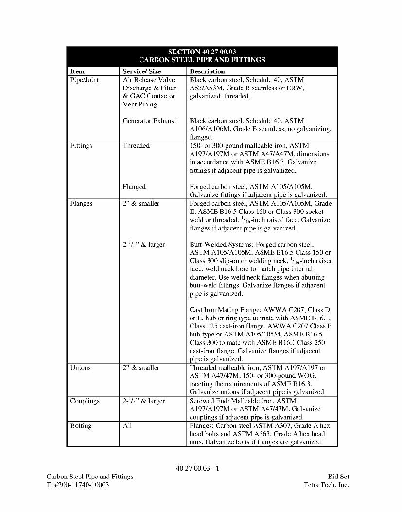
Item Service/ Size DescriptionPipe/Joint Air Release Valve Black carbon steel, Schedule 40, ASTM
Discharge & Filter A53/A53M, Grade B seamless or ERW,& GAC Contactor galvanized, threaded.Vent Piping
Generator Exhaust Black carbon steel, Schedule 40, ASTMA106/A106M, Grade B seamless, no galvanizing,flanged.
Fittings Threaded 150- or 300-pound malleable iron, ASTMA197/A197M or ASTM A47/A47M, dimensionsin accordance with ASME B16.3. Galvanizefittings if adjacent pipe is galvanized.
Flanged Forged carbon steel, ASTM A105/A105M.Galvanize fittings if adjacent pipe is galvanized.
Flanges 2" & smaller Forged carbon steel, ASTM A105/A105M, GradeII, ASME B16.5 Class 150 or Class 300 socket-weld or threaded, 1/is-inch raised face. Galvanizeflanges if adjacent pipe is galvanized.
2-1/2" & larger Butt-Welded Systems: Forged carbon steel,ASTM A105/A105M, ASME B16.5 Class 150 orClass 300 slip-on or welding neck, 1/is-inch raisedface; weld neck bore to match pipe internaldiameter. Use weld neck flanges when abuttingbutt-weld fittings. Galvanize flanges if adjacentpipe is galvanized.
Cast Iron Mating Flange: AWWA C207, Class Dor E, hub or ring type to mate with ASME B16.1,Class 125 cast-iron flange. AWWA C207 Class Fhub type or ASTM A105/105M, ASME B16.5Class 300 to mate with ASME B16.1 Class 250cast-iron flange. Galvanize flanges if adjacentpipe is galvanized.
Unions 2" & smaller Threaded malleable iron, ASTM A197/A197 orASTM A47/47M, 150- or 300-pound WOG,meeting the requirements of ASME B16.3.Galvanize unions if adjacent pipe is galvanized.
Couplings 2-1/2" & larger Screwed End: Malleable iron, ASTMA197/A197M or ASTM A47/47M. Galvanizecouplings if adjacent pipe is galvanized.
Bolting All Flanges: Carbon steel ASTM A307, Grade A hexhead bolts and ASTM A563, Grade A hex headnuts. Galvanize bolts if flanges are galvanized.
40 27 00.03 - 1Carbon Steel Pipe and Fittings Bid SetTt #200-11740-10003 Tetra Tech, Inc.
SECTION 40 27 00.03CARBON STEEL PIPE AND FITTINGS
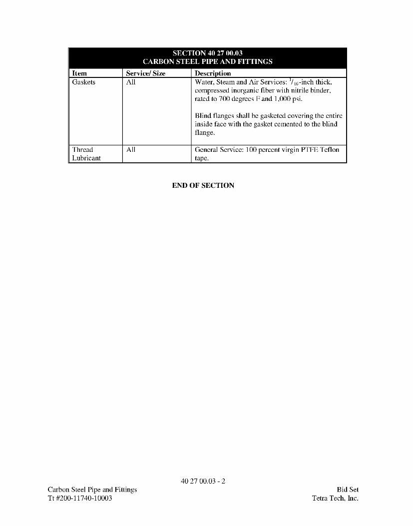
Item Service/ Size DescriptionGaskets All Water, Steam and Air Services: '/is-inch thick,
compressed inorganic fiber with nitrile binder,rated to 700 degrees F and 1,000 psi.
Blind flanges shall be gasketed covering the entireinside face with the gasket cemented to the blindflange.
Thread All General Service: 100 percent virgin PTFE TeflonLubricant tape.
END OF SECTION
40 27 00.03 - 2Carbon Steel Pipe and Fittings Bid SetTt #200-11740-10003 Tetra Tech, Inc.
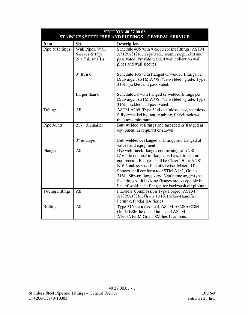
Item | Size DescriptionPipe & Fittings | Wall Pipes, Wall Schedule 40S with welded socket fittings: ASTM
Sleeves & Pipe A312/A312M, Type 316L seamless, pickled and2-1/2" & smaller passivated. Provide welded wall collars on wall
pipes and wall sleeves.
3" thru 6" Schedule 10S with flanged or welded fittings perDrawings: ASTM A778, "as-welded" grade, Type316L, pickled and passivated.
Larger than 6" Schedule 5S with flanged or welded fittings perDrawings: ASTM A778, "as-welded" grade, Type316L, pickled and passivated.
Tubing | All ASTM A269, Type 316L stainless steel, seamless,fully annealed hydraulic tubing, 0.065-inch wallthickness minimum.
Pipe Joints | 21/2" & smaller Butt welded at fittings and threaded or flanged atequipment as required or shown.
3" & larger Butt welded or flanged at fittings and flanged atvalves and equipment.
Flanged | All Use weld-neck flanges conforming to ANSIB16.5 to connect to flanged valves, fittings, orequipment. Flanges shall be Class 150 or ANSIB16.5 unless specified otherwise. Material forflanges shall conform to ASTM A182, Grade316L. Slip-on flanges and Van Stone angle-typeface rings with backing flanges are acceptable inlieu of weld-neck flanges for backwash air piping.
Tubing Fittings | All Flareless Compression Type Forged: ASTMA182/A182M, Grade F316, Parker-HannifinFerulok, Flodar BA Series.
Bolting | All Type 316 stainless steel, ASTM A320/A320MGrade B8M hex head bolts and ASTMA194/A194M Grade 8M hex head nuts.
40 27 00.08 - 1Stainless Steel Pipe and Fittings - General Service Bid SetTt #200-11740-10003 Tetra Tech, Inc.

SECTION 40 27 00.08STAINLESS STEEL PIPE AND FITTINGS - GENERAL SERVICE
Item Size DescriptionGaskets All Flanges Flanged, Water and Sewage Service: '/s-inch
thick, unless otherwise specified, red rubber(SBR), hardness 80 (Shore A), rated to 200degrees F, conforming to ASME B16.21, AWWAC207, and ASTM D1330, Grade 1 and Grade 2.
Hot Air, and Fuel Gas Service: 1/s-inch thick,unless otherwise specified, homogeneous blackrubber (EPDM), hardness 60 (Shore A), rated to300 degrees F, conforming to ASME B16.21 andASTM D1330 Steam Grade.
Blind flanges shall be gasketed covering entireinside face with gasket cemented to blind flange.
Thread 2" & smaller General Service: 100% virgin PTFE Teflon tape.Lubricant
END OF SECTION
40 27 00.08 - 2Stainless Steel Pipe and Fittings - General Service Bid SetTt #200-11740-10003 Tetra Tech, Inc.

Item Service DescriptionGeneral All Materials in contact with potable water shall conform to
NSF Standard 61.Piping Chemical Feed Lines, Schedule 80 PVC: Type I, Grade I or Class 12454-B
Sample Lines & conforming to ASTM D1784 and ASTM D1785. Pipe shallSecondary Containment be manufactured with titanium dioxide for ultraviolet
protection.
Sanitary Sewer & Drains SDR 26 conforming to ASTM D3034Upstream of FiltratePump Station
Underdrains SDR 26 conforming to ASTM D3034. Perforation shallcomply with ASTM F-758.
Threaded Nipples Schedule 80 PVC.Tubing Chemical Feed Provide black PVC tubing with nylon braid reinforcement
embedded in the wall of the tubing with smooth inside boreand smooth outside where PVC tubing is called for in theDrawings. Design for continuous indoor and outdoor(ultraviolet-resistant) service. Minimum operating pressureshall be 200 psi for tubing 1/2 inch and smaller, 150 psi for3/4 inch, 100 psi for 1 and 1-1/4 inches, and 75 psi for 1-1/2 inches. Burst pressure shall be at least 4.0 times thespecified operating pressure. Join tubing to pipe with asingle-barb male adapter fitting. Secure tubing to the fittingwith a stainless steel hose clamp. Connect tubing sectionsby means of barbed insert-type hose fittings with stainlesssteel clamp.Products: Ryan-Herco "Herco-Chemical Black PVC Hose"or Engineer approved equal.Test pressure for PVC tubing shall be the same as the PVCpiping to which it is connected.
Fittings All Schedule, SDR, or pressure class of fittings shall matchadjacent pipe. Solvent weld fittings shall conform toASTM D2467. Threaded fittings shall conform to ASTMD2464. Exposed fittings shall be manufactured withtitanium dioxide for ultraviolet protection.
Joints Chemical Feed & Solvent socket weld except where connection to threadedSample Lines or flanged valves and equipment may require future
disassembly.
Drains Upstream of Push-on joints conforming to ATM D-3212.Filtrate Pump Station
Underdrains Solvent socket weld or push-on joints.
40 27 00.10 - 1Polyvinyl Chloride (PVC) Pipe and Fittings Bid SetTt #200-11740-10003 Tetra Tech, Inc.
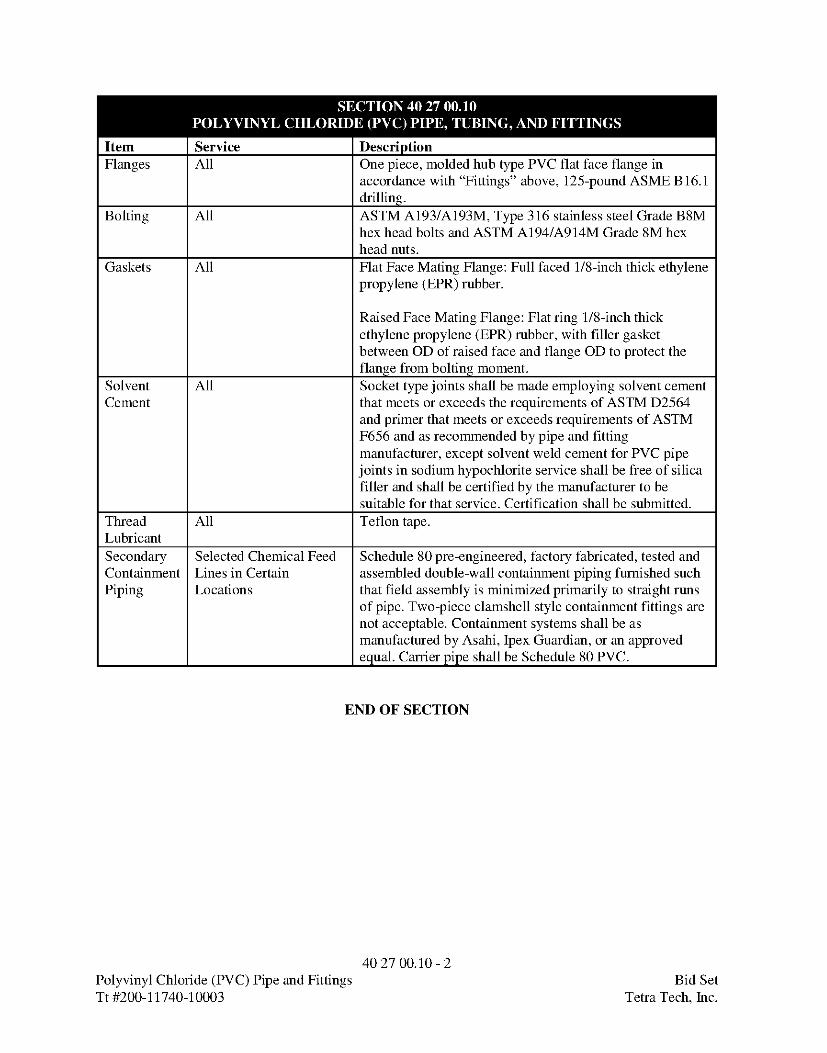
Item Service DescriptionFlanges All One piece, molded hub type PVC flat face flange in
accordance with "Fittings" above, 125-pound ASME B16.1drilling.
Bolting All ASTM A193/A193M, Type 316 stainless steel Grade B8Mhex head bolts and ASTM A194/A914M Grade 8M hexhead nuts.
Gaskets All Flat Face Mating Flange: Full faced 1/8-inch thick ethylenepropylene (EPR) rubber.
Raised Face Mating Flange: Flat ring 1/8-inch thickethylene propylene (EPR) rubber, with filler gasketbetween OD of raised face and flange OD to protect theflange from bolting moment.
Solvent All Socket type joints shall be made employing solvent cementCement that meets or exceeds the requirements of ASTM D2564
and primer that meets or exceeds requirements of ASTMF656 and as recommended by pipe and fittingmanufacturer, except solvent weld cement for PVC pipejoints in sodium hypochlorite service shall be free of silicafiller and shall be certified by the manufacturer to besuitable for that service. Certification shall be submitted.
Thread All Teflon tape.LubricantSecondary Selected Chemical FeedContainment Lines in CertainPiping Locations
Schedule 80 pre-engineered, factory fabricated, tested andassembled double-wall containment piping furnished suchthat field assembly is minimized primarily to straight runsof pipe. Two-piece clamshell style containment fittings arenot acceptable. Containment systems shall be asmanufactured by Asahi, Ipex Guardian, or an approvedequal. Carrier pipe shall be Schedule 80 PVC.
END OF SECTION
40 27 00.10 - 2Polyvinyl Chloride (PVC) Pipe and Fittings Bid SetTt #200-11740-10003 Tetra Tech, Inc.

Item Size DescriptionPiping All Schedule 80 CPVC: Type IV, Grade I or Class
23447-B conforming to ASTM D1784 and ASTMF441. Pipe shall be manufactured with titaniumdioxide for ultraviolet protection.
Threaded nipples shall be Schedule 80.Fittings All Schedule to Match Pipe Above: ASTM D2466
and ASTM F349 for socket weld type andSchedule 80 ASTM F437 for threaded type.Fittings shall be manufactured with titaniumdioxide for ultraviolet protection.
Joints All Solvent socket weld except where connection tothreaded valves and equipment may require futuredisassembly.
Flanges All One piece, molded hub type CPVC flat faceflange in accordance with Fittings above, 125-pound ASME B16.1 drilling.
Bolting All Flat Face Mating Flange and In Corrosive Areas:ASTM A193/A193M, Type 316 stainless steelGrade B8M hex head bolts and ASTMA194/A914M Grade8M hex head nuts.
Raised Face Mating Flange: Carbon steel ASTMA307 Grade B square head bolts and ASTM A563Grade A heavy hex head nuts.
Gaskets All Flat Face Mating Flange: Full faced 1/g-inch thickethylene propylene (EPR) rubber.
Raised Face Mating Flange: Flat ring 1/g-inch
thick ethylene propylene (EPR) rubber, with fillergasket between OD of raised face and flange ODto protect the flange from bolting moment.
Solvent All All socket type joints shall be made employingCement primer and solvent cements that meet or exceed
the requirements of ASTM F493 and primers thatmeet or exceed requirements of ASTM F656 andas recommended by pipe and fitting manufacturer,except solvent weld cement for CPVC pipe jointsin sodium hypochlorite service shall be free ofsilica filler and shall be certified by themanufacturer to be suitable for that serviceCertification shall be submitted. Solvent cementand primer shall be listed by NSF for use withpotable water.
40 27 00.11 - 1Chlorinated Polyvinyl Chloride (CPVC) Pipe and Fittings Bid SetTt #200-11740-10003 Tetra Tech, Inc.
SECTION 40 27 00.11CHLORINATED POLYVINYL CHLORIDE (CPVC) PIPE AND FITTINGS
Item Size DescriptionThread All Teflon tape.Lubricant
END OF SECTION
40 27 00.11 - 2Chlorinated Polyvinyl Chloride (CPVC) Pipe and Fittings Bid SetTt #200-11740-10003 Tetra Tech, Inc.

SECTION 40 27 01PROCESS PIPING SPECIALTIES
PART 1 GENERAL
1.01 REFERENCES
A. The following is a list of standards which may be referenced in this Section:
1. American Society of Mechanical Engineers (ASME):a. B 16.1, Gray Iron Pipe Flanges and Flanged Fittings.b. B16.5, Pipe Flanges and Flanged Fittings: NPS 1/2 through NPS
24.
2. American Water Works Association (AWWA):a. C153, A21.53, Ductile-Iron Compact Fittings for Water Service.b. C210, Liquid-Epoxy Coating Systems for the Interior and Exterior
of Steel Water Pipelines.c. C213, Fusion-Bonded Epoxy Coating for the Interior and Exterior
of Steel Water Pipelines.d. C219, Bolted, Sleeve-Type Couplings for Plain-End Pipe.e. C800, Underground Service Line Valves and Fittingsf. Manual Mll, Steel Pipe-A Guide for Design and Installation.
3. ASTM International (ASTM):a. A153/A153M7 Standard Specification for Zine Coating (Hot-Dip)
on Iron and Steel Hardware.b. A276, Standard Specification for Stainless Steel Bars and Shapes.
4. National Fire Protection Association (NFPA): 24, Standard for theInstallation of Private Fire Service Mains and Their Appurtenances.
5. NSF International (NSF): NSF 61, Drinking Water System Components-Health Effects.
1.02 SUBMITTALS
A. Manufacturer's data on materials, construction, end connections, ratings, overalllengths, and live lengths (as applicable) per Section 01 33 00, SubmittalProcedures.
B. Operation and Maintenance Data as specified in Section 01 78 23, Operation andMaintenance Data.
40 27 01 - 1Process Piping Specialties Bid SetTt#200-11740-10003 Teka Tech,Inc.

PART 2 PRODUCTS
2.01 GENERAL
A. Provide required piping specialty items, whether shown or not shown onDrawings, as required by applicable codes and standard industry practice.
B. Rubber ring joints, mechanical joints, flexible couplings, and proprietaryrestrained ductile iron pipe joints are considered flexible joints; welded, screwed,and flanged pipe joints are not considered flexible.
C. All products shall be suitable for contact with potable water or chemicals that willbe added to potable water pursuant to NSF Standard 61.
2.02 CONNECTORS
A. Elastomer Bellows Connectors or Expansion Joints in Exposed Piping:
1. Type: Fabricated spool with single filled arch.
2. Materials: Elastomeric tube with reinforcement, lining, and cover.
3. End Connections: Flanged, drilled 125-pound ASME B16.1 standard, withfull elastomer face and galvanized steel retaining rings.
4. Working Pressure Rating:
a. All Applications Except Finished Water Pumps: 150 psi.
b. Finished Water Pumps: 225 psi.
5. Thrust Restraint: Galvanized steel control rods to limit travel of elongationand compression. Number and size of rods shall be sufficient to restrainagainst force developed as a result of pressure test.
6. Manufacturers and Products:a. Red Valve.b. General Rubber.c. Or equal.
2.03 COUPLINGS
A. General:
4027 01 - 2Process Piping Specialties Bid SetTt#200-11740-10003 Teka Tech,Inc.

1. Couplings shall be rated for working pressure not less than the testpressure set forth in Piping Schedule for the service and not less than 150psi.
2. Couplings shall be lined and coated with fusion-bonded epoxy inaccordance with AWWA C213.
3. Provide restraint appropriate for test and operating pressures.
4. Sleeve type couplings shall conform to AWWA C219 and shall behydraulically expanded beyond minimum yield for accurate sizing andproofing of tensile strength.
B. Flexible Sleeve Type Coupling:
1. Pressure Rating: Per Paragraph 2.03Al above.
2. Thrust Restraint: Galvanized steelæntrol rods to restrain force developed byspecified test pressure.
3. Manufacturers and Products:a. Steel Pipe:
1) Dresser Piping Specialties Style 38.2) Smith-Blair, Inc. Style 411.
b. Ductile Iron Pipe:1) Dresser Piping Specialties Style 253.2) Smith-Blair, Inc. Style 411.
C. Restrained Flange Adapter:
1. Pressure Rating:a. Pressure Rating: Per Paragraph 2.03Al above.b. Safety Factor: Not less than two times working pressure and shall
be supported by manufacturer's proof testing.
2. Thrust Restraint:a. Provide hardened steel wedges that bear against and engage outer
pipe surface, and allow articulation of pipe joint after assemblywhile wedges remain in their original setting position on pipesurface.
b. Products employing set screws that bear directly on pipe areacceptable.
3. Manufacturers: EBAA Iron Sales Co.; Dresser, Smith-Blair or anapproved equal.
40 27 01 - 3Process Piping Specialties Bid SetTt#200-11740-10003 Teka Tech,Inc.
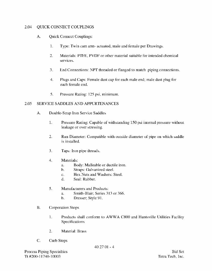
2.04 QUICK CONNECT COUPLINGS
A. Quick Connect Couplings:
1. Type: Twin cam arm- actuated, male and female per Drawings.
2. Materials: PTFE, PVDF or other material suitable for intended chemicalservices.
3. End Connections: NPT threaded or flanged to match piping connections.
4. Plugs and Caps: Female dust cap for each male end; male dust plug foreach female end.
5. Pressure Rating: 125 psi, minimum.
2.05 SERVICE SADDLES AND APPURTENANCES
A. Double-Strap Iron Service Saddles
1. Pressure Rating: Capable of withstanding 150 psi internal pressure withoutleakage or over stressing.
2. Run Diameter: Compatible with outside diameter of pipe on which saddleis installed.
3. Taps: Iron pipe threads.
4. Materials:a. Body: Malleable or ductile iron.b. Straps: Galvanized steel.c. Hex Nuts and Washers: Steel.d. Seal: Rubber.
5. Manufacturers and Products:a. Smith-Blair; Series 313 or 366.b. Dresser; Style 91.
B. Corporation Stops
1. Products shall conform to AWWA C800 and Huntsville Utilities FacilitySpecifications
2. Material: Brass
C. Curb Stops
40 27 01 - 4Process Piping Specialties Bid SetTt#200-11740-10003 Teka Tech,Inc.

1. Products shall conform to AWWA C800 and Huntsville Utilities FacilitySpecifications
2. Material: Brass
D. Service Line: Polyethylene per Huntsville Utilities Facility Specifications.
2.06 SLEEVED WALL AND FLOOR PENETRATIONS
A. Wall Sleeves:
1. Minimum Thickness: Schedule 40.
2. Factory Finish: Galvanizing, hot-dip applied meeting requirements ofASTM A153/A153M.
B. Compression Type Wall Seal:
1. Type: Interconnected synthetic rubber links shaped and sized tocontinuously fill annular space between pipe and wall sleeve opening.
2. Fabrication:a. Assemble interconnected rubber links with ASTM A276, Type 316
stainless steel bolts and nuts.b. Pressure plates shall be reinforced nylon polymer.
3. Size: According to manufacturer's instructions for size of pipes shown toprovide a watertight seal between pipe and wall sleeve opening, and towithstand a hydrostatic head of 40 feet of water.
4. Manufacturer: Thunderline Corp., Link-Seal Division or an approvedequal.
C. Insulated Wall Thimbles
1. Minimum Insulation Thickness: 2 inches
2. Material: Type 316 stainless steel construction
3. NFPA rated for 2,300 degrees F.
2.07 SLAB, FLOOR, WALL, AND ROOF PENETRATIONS FOR CARRIER PIPES
A. Ductile Iron Wall Pipe:
40 27 01 - 5Process Piping Specialties Bid SetTt#200-11740-10003 Teka Tech,Inc.

1. Diameter and Ends: Per Drawings.
2. Thickness: Equal to or greater than adjacent piping.
3. Collars: Ductile iron cast integral with wall pipe wherever possible orwelded attachment to wall pipe.
4. Manufacturers:a. American Cast Iron Pipe Co.b. U.S. Pipe and Foundry Co.
B. Steel or Stainless Steel Wall Pipe:
1. Same material and wall thickness as adjacent pipe, except ¼-inchminimum thickness.
2. Lining: Same as connecting pipe.
3. Collars:a. Outside Diameter: Unless otherwise shown, 3 inches greater than
outside diameter of wall pipe.b. Continuously fillet welded on each side all around.
2.08 MISCELLANEOUS SPECIALTIES
A. Strainers, Water Service, 2 Inches and Smaller:
1. Type: Bronze body, Y-pattern, 200 psi nonshock rated, with screwedgasketed bronze cap.
2. Screen: Heavy-gauge Type 304 stainless steel or Monel, 20-mesh.
3. Manufacturers and Productsa. Armstrong International; Inc.; Model F.b. Mueller Steam Specialty; Model 1351M.c. Approved equal.
B. Strainers, Water Service, 2 ½ Inches and Larger:
1. Type: Cast iron or ductile iron body, Y-pattern, 175 psi nonshock ratedwith flanged gasketed iron cap.
2. Screen: Heavy-gauge Type 316 stainless steel, 0.045-inch perforations.
3. Manufacturers and Products:a. Armstrong International, Inc.; Model A7FL 125.
40 27 01 - 6Process Piping Specialties Bid SetTt#200-11740-10003 Teka Tech,Inc.

b. Mueller Steam Specialty; Model 751.c. Approved equal.
C. Strainers, Plastic Piping Systems, 4 Inches and Smaller:
1. Type: Y-pattern PVC body, 150 psi nonshock rated with screwed PVC capand Viton seals.
2. End Connections: Screwed or solvent weld for strainers 2 inches andsmaller. Class 150 ANSI flanged for strainers 2 ½ inches and larger.
3. Screen: Heavy-gauge PVC, 1/32-inch mesh, minimum 2 to 1 screen areato pipe size ratio.
4. Manufacturersa. Hayward.b. Spearsc. Approved equal.
D. Water Hose:
1. Furnish eight (8) 50-foot lengths of 1-inch and ten (10) 50-foot lengths of1-1/2-inch rubber hose. Hoses shall have EPDM black cover and EPDMtube and be reinforced with two textile braids. Provide each length withbrass male and female NST hose thread couplings to fit hose nozzle andhose valve.
2. Rated minimum working pressure of hose shall be 200 psi.
3. Manufacturers:a. Goodyear.b. Boston.c. Approved equal.
E. Hose Nozzles:
1. Furnish eight (8) 1-inch and eight (8) 1 ½ inch cast brass, satin finish,nozzles with adjustable fog, straight-stream, and shut-off feature andrubber bumper. Provide nozzles with female NST hose thread.
2. Manufacturers:a. Croker.b. Elkhart.c. Approved equal.
F. Pressure Gauge Assemblies
40 27 01 - 7Process Piping Specialties Bid SetTt#200-11740-10003 Teka Tech,Inc.
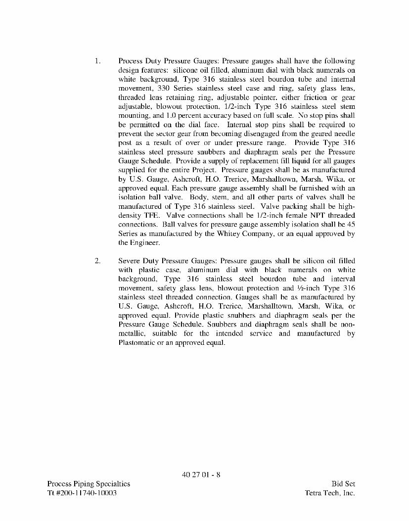
1. Process Duty Pressure Gauges: Pressure gauges shall have the followingdesign features: silicone oil filled, aluminum dial with black numerals onwhite background, Type 316 stainless steel bourdon tube and internalmovement, 330 Series stainless steel case and ring, safety glass lens,threaded lens retaining ring, adjustable pointer, either friction or gearadjustable, blowout protection, 1/2-inch Type 316 stainless steel stemmounting, and 1.0 percent accuracy based on full scale. No stop pins shallbe permitted on the dial face. Internal stop pins shall be required toprevent the sector gear from becoming disengaged from the geared needlepost as a result of over or under pressure range. Provide Type 316stainless steel pressure snubbers and diaphragm seals per the PressureGauge Schedule. Provide a supply of replacement fill liquid for all gaugessupplied for the entire Project. Pressure gauges shall be as manufacturedby U.S. Gauge, Ashcroft, H.O. Trerice, Marshalltown, Marsh, Wika, orapproved equal. Each pressure gauge assembly shall be furnished with anisolation ball valve. Body, stem, and all other parts of valves shall bemanufactured of Type 316 stainless steel. Valve packing shall be high-density TFE. Valve connections shall be 1/2-inch female NPT threadedconnections. Ball valves for pressure gauge assembly isolation shall be 45Series as manufactured by the Whitey Company, or an equal approved bythe Engineer.
2. Severe Duty Pressure Gauges: Pressure gauges shall be silicon oil filledwith plastic case, aluminum dial with black numerals on whitebackground, Type 316 stainless steel bourdon tube and intervalmovement, safety glass lens, blowout protection and ½-inch Type 316stainless steel threaded connection. Gauges shall be as manufactured byU.S. Gauge, Ashcroft, H.O. Trerice, Marshalltown, Marsh, Wika, orapproved equal. Provide plastic snubbers and diaphragm seals per thePressure Gauge Schedule. Snubbers and diaphragm seals shall be non-metallic, suitable for the intended service and manufactured byPlastomatic or an approved equal.
40 27 01 - 8Process Piping Specialties Bid SetTt#200-11740-10003 Teka Tech,Inc.
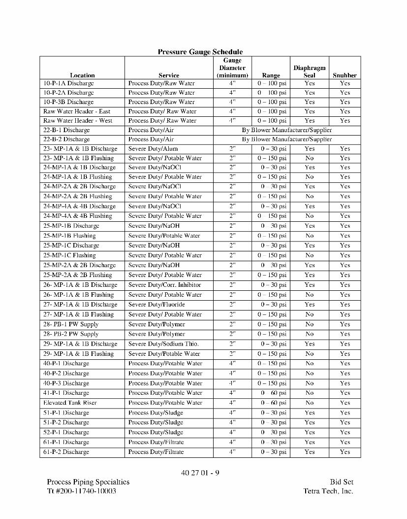
Pressure Gauge ScheduleGauge
Diameter DiaphragmLocation Service (minimum) Range Seal Snubber
10-P-1A Discharge Process Duty/Raw Water 4" 0 - 100 psi Yes Yes
10-P-2A Discharge Process Duty/Raw Water 4" 0 - 100 psi Yes Yes
10-P-3B Discharge Process Duty/Raw Water 4" 0 - 100 psi Yes Yes
Raw Water Header - East Process Duty/ Raw Water 4" 0 - 100 psi Yes Yes
Raw Water Header - West Process Duty/ Raw Water 4" 0 - 100 psi Yes Yes
22-B-1 Discharge Process Duty/Air By Blower Manufacturer/Supplier
22-B-2 Discharge Process Duty/Air By Blower Manufacturer/Supplier
23- MP-1A & 1B Discharge Severe Duty/Alum 2" 0 - 30 psi Yes Yes
23- MP-1A & 1B Flushing Severe Duty/ Potable Water 2" 0 - 150 psi No Yes
24-MP-1A & 1B Discharge Severe Duty/NaOCl 2" 0 - 30 psi Yes Yes
24-MP-1A & 1B Flushing Severe Duty/ Potable Water 2" 0 - 150 psi No Yes
24-MP-2A & 2B Discharge Severe Duty/NaOCl 2" 0 - 30 psi Yes Yes
24-MP-2A & 2B Flushing Severe Duty/ Potable Water 2" 0 - 150 psi No Yes
24-MP-4A & 4B Discharge Severe Duty/NaOCl 2" 0 - 30 psi Yes Yes
24-MP-4A & 4B Flushing Severe Duty/ Potable Water 2" 0 - 150 psi No Yes
25-MP-1B Discharge Severe Duty/NaOH 2" 0 - 30 psi Yes Yes
25-MP-1B Flushing Severe Duty/Potable Water 2" 0 - 150 psi No Yes
25-MP-1 C Discharge Severe Duty/NaOH 2" 0 - 30 psi Yes Yes
25-MP-lC Flushing Severe Duty/ Potable Water 2" 0 - 150 psi No Yes
25-MP-2A & 2B Discharge Severe Duty/NaOH 2" 0 - 30 psi Yes Yes
25-MP-2A & 2B Flushing Severe Duty/ Potable Water 2" 0 - 150 psi Yes Yes
26- MP-1A & 1B Discharge Severe Duty/Corr. Inhibitor 2" 0 - 30 psi Yes Yes
26- MP-1A & 1B Flushing Severe Duty/ Potable Water 2" 0 - 150 psi No Yes
27- MP-1A & 1B Discharge Severe Duty/Fluoride 2" 0 - 30 psi Yes Yes
27- MP-1A & 1B Flushing Severe Duty/ Potable Water 2" 0 - 150 psi No Yes
28- PB-1 PW Supply Severe Duty/Polymer 2" 0 - 150 psi No Yes
28- PB-2 PW Supply Severe Duty/Polymer 2" 0 - 150 psi No Yes
29- MP-1A & 1B Discharge Severe Duty/Sodium Thio. 2" 0 - 30 psi Yes Yes
29- MP-1A & 1B Flushing Severe Duty/Potable Water 2" 0 - 150 psi No Yes
40-P-1 Discharge Process Duty/Potable Water 4" 0 - 150 psi No Yes
40-P-2 Discharge Process Duty/Potable Water 4" 0 - 150 psi No Yes
40-P-3 Discharge Process Duty/Potable Water 4" 0 - 150 psi No Yes
41-P-1 Discharge Process Duty/Potable Water 4" 0 - 60 psi No Yes
Elevated Tank Riser Process Duty/Potable Water 4" 0 - 60 psi No Yes
51-P-1 Discharge Process Duty/Sludge 4" 0 - 30 psi Yes Yes
51-P-2 Discharge Process Duty/Sludge 4" 0 - 30 psi Yes Yes
52-P-1 Discharge Process Duty/Sludge 4" 0 - 30 psi Yes Yes
61-P-1 Discharge Process Duty/Filtrate 4" 0 - 30 psi Yes Yes
61-P-2 Discharge Process Duty/Filtrate 4" 0 - 30 psi Yes Yes
40 27 01 - 9Process Piping Specialties Bid SetTt#200-11740-10003 TekaTech,Inc.
PART 3 EXECUTION
3.01 GENERAL
A. Provide accessibility to piping specialties for control and maintenance.
3.02 PIPING FLEXIBILITY PROVISIONS
A. General:
1. Thrust restraint shall be provided as specified in Section 40 27 00, ProcessPiping-General.
2. Install flexible couplings to facilitate piping installation, in accordancewith approved shop drawings.
B. Flexible Joints at Concrete Backfill or Encasement: Install within 18 inches orone-half pipe diameter, whichever is less, from the termination of any concretebackfill or concrete encasement.
C. Flexible Joints at Concrete Structures:
1. Install 18 inches or less from face of structures; joint may be flush withface.
3.03 COUPLINGS
A. General:
1. Install in accordance with manufacturer's written instructions.
2. Before installation clean pipe holdback area of oil, scale, rust, and dirt.
3. Do not remove pipe coating. If damaged, repair before joint is made.
3.04 SLAB, FLOOR, ROOF, AND WALL PENETRATIONS
A. Installation:
1. Support securely in formwork to prevent contact with reinforcing steel andtie-wires.
2. Caulk joint with specified sealant in non-submerged applications and sealbelow grade and submerged applications with wall penetration seal.
END OF SECTION
40 27 01 - 10Process Piping Specialties Bid SetTt#200-11740-10003 Teka Tech,Inc.
SECTION 40 27 02PROCESS VALVES AND OPERATORS
PART 1 GENERAL
1.01 REFERENCES
A. The following is a list of standards which may be referenced in this Section:
1. American National Standards Institute (ANSI): B16.1, Cast Iron PipeFlanges and Flanged Fittings.
2. American Society of Sanitary Engineers (ASSE): 1011, PerformanceRequirements for Hose Connection Vacuum Breakers.
3. American Water Works Association (AWWA):a. C111/A21.11, Rubber-Gasket Joints for Ductile-Iron Pressure Pipe
and Fittings.b. C504, Rubber-Seated Butterfly Valves.c. C507, Ball Valves.d. C508, Swing-Check Valves for Waterworks Service.e. C509, Resilient-Seated Gate Valves for Water Supply Service.f. C510, Double Check Valve, Backflow Prevention Assembly.g. C511, Reduced-Pressure Principle Backflow Prevention Assembly.h. C541, Hydraulic and Pneumatic Cylinder and Vane-Type
Actuators for Valves and Slide Gatesi. C550, Protective Interior Coatings for Valves and Hydrants.j. C800, Underground Service Line Valves and Fittings.
4. ASTM International (ASTM):a. A276, Standard Specification for Stainless Steel Bars and Shapes.b. A351/A351M, Standard Specification for Castings, Austenitic, for
Pressure-Containing Parts.c. A564/A564M, Standard Specification for Hot-Rolled and Cold-
Finished Age-Hardening Stainless Steel Bars and Shapes.d. B62, Standard Specification for Composition Bronze or Ounce
Metal Castings.e. B127, Standard Specification for Nickel-Copper Alloy (UNS
N04400) Plate, Sheet, and Strip.f. B139, Standard Specification for Phosphor Bronze Rod, Bar and
Shapes.g. B164, Standard Specification for Nickel-Copper Alloy Rod, Bar,
and Wire.h. B194, Standard Specification for Copper-Beryllium Alloy Plate,
Sheet, Strip, and Rolled Bar.i. B584, Standard Specification for Copper Alloy Sand Castings for
General Applications.
40 27 02 - 1Process Valves and Operators Bid SetTt#200-11740-10003 Teka Tech,Inc.

j. D429, Standard Test Methods for Rubber Property-Adhesion toRigid Substrates.
k. D1784, Standard Specification for Rigid Polyvinyl Chloride (PVC)Compounds and Chlorinated Polyvinyl Chloride (CPVC)Compounds.
5. FM Global (FM).6. Food and Drug Administration (FDA).7. International Association of Plumbing and Mechanical Officials
(IAPMO).8. Manufacturers Standardization Society (MSS):
a. SP-80, Bronze Gate, Globe, Angle and Check Valves.b. SP-110, Ball Valves Threaded, Socket-Welding, Solder Joint,
Grooved and Flared Ends9. NSF International (NSF): Standard 61, Drinking Water System
Components- Health Effects.10. Occupational Safety & Health Administration (OSHA): Regulation 29
CFR 1910.147, The Control of Hazardous Energy (Lockout/Tagout) -Inspection Procedures and Interpretive Guidance.
11. Underwriters Laboratories (UL).12. USC Foundation for Cross-Connection Control and Hydraulic Research.
1.02 SUBMITTALS
A. Action Submittals:
1. Shop Drawings:a. Product data sheets for each make and model. Indicate valve type
number, applicable tag number, and facility name/number orservice where used.
b. Complete catalog information, descriptive literature, specifications,and identification of materials of construction.
c. Power and control wiring diagrams, including terminals andnumbers.
d. For each electric, pneumatic, or hydraulic actuator provided,manufacturer's standard data sheet, with application specificfeatures and options clearly identified.
e. Sizing calculations for open-close/throttle and modulating valves.
B. Informational Submittals:
1. Manufacturer's Certificate of Compliance, in accordance with Section 0143 33, Manufacturers' Field Services for:a. Pneumatic actuators; full compliance with AWWA C541.b. Butterfly valves; full compliance with AWWA C504.c. Finished Water Pump Control Valves; full compliance with
AWWA C507.
40 27 02 - 2Process Valves and Operators Bid SetTt#200-11740-10003 Teka Tech,Inc.

d. Pressure Relief and Surge Anticipator Valves.e. Pressure Reducing Valves.f. Swing Check Valves.g. Air Release Valves.
2. Tests and inspection data.3. Operation and Maintenance Data as specified in Section 01 78 23,
Operation and Maintenance Data.4. Manufacturer's Certificate of Proper Installation, in accordance with
Section 01 43 33, Manufacturers' Field Services.
PART 2 PRODUCTS
2.01 GENERAL
A. Valves to include operator, actuator, handwheel, chain wheel, extension stem,floor stand, operating nut, chain, wrench, and accessories to allow a completeoperation from the intended operating level.
B. Valves are to be suitable for intended service.
C. Valve shall be same size as adjoining pipe, unless otherwise called out onDrawings or in Valve Schedule.
D. Valve ends to suit adjacent piping.
E. Resilient seated valves shall have no leakage (drop-tight) in either direction atvalve rated design pressure. All other valves shall have no leakage (drip-tight) ineither direction at valve rated design pressure, unless otherwise allowed for in thisSection or in stated valve standard.
F. Size operators and actuators to operate valve for the full range of pressures andvelocities.
G. Valves to open by turning counterclockwise.
H. Factory mount operator, actuator, and accessories to maximum extent that ispractical.
I. Valves for water and chemical service shall be NSF Standard 61 certified for theintended application.
2.02 MATERIALS
A. Bronze and brass valve components and accessories that have surfaces in contactwith water shall be alloys containing less than 16 percent zine and 2 percentaluminum.
40 27 02 - 3Process Valves and Operators Bid SetTt#200-11740-10003 Teka Tech,Inc.
1. Approved alloys are of the following ASTM designations: B61, B62,B98/B98M (Alloy UNS No. C65100, C65500, or C66100), B139 (AlloyUNS No. C51000), B584 (Alloy UNS No. C90300 or C94700), B64,B194, and B127.
2. Stainless steel Alloy 18-8 may be substituted for bronze.
2.03 FACTORY FINISHING
A. Epoxy Lining and Coating:
1. Use where specified for individual valves described herein.2. In accordance with AWWA C550 unless otherwise specified.3. Either two-part liquid material or heat-activated (fusion) material except
only heat-activated material if specified as "fusion" or "fusion epoxy".4. Minimum 7-mil dry film thickness except where limited by valve
operating tolerances.
B. Exposed Valves:
1. Paint in accordance with Section 09 90 00, Painting and Coating.2. Safety isolation valves and lockout valves with handles, handwheels, or
chain wheels shall be "safety yellow".
2.04 VALVES
A. Gate Valves:
1. Gate Valves Smaller than 2 Inches, Buried or Above-Grade Service:a. All bronze, screwed bonnet, packed gland, single solid wedge
gate, nonrising stem, Class 125 rated 200 psi CWP, compliantwith MSS SP-80 Type 1, threaded ends.
b. Manufacturers:1) Crane.
2) Stockham.3) Approved equal.
2. Resilient Seated Gate Valve 2 Inches to 12 Inches, Buried Service:a. Iron body, resilient seat, bronze stem and stem nut, nonrising stem,
in accordance with AWWA C509, 2-inch operating nut, full port,fusion-epoxy coated inside and outside per AWWA C550,mechanical joint ends for 3-inch and larger valves, screwed endsfor 2-1/2-inch and smaller valves, NSF 61 certified, minimumdesign working water pressure of 200 psig. Tapping valves shallconform to the above requirements and have one flanged end
40 27 02 - 4Process Valves and Operators Bid SetTt#200-11740-10003 Teka Tech,Inc.
designed for connection to a tapping sleeve and one mechanicaljoint end for connection to the branch piping.
b. Manufacturers:1) American Flow Control.2) M&H Valve.3) Approved equal.
3. Resilient Seated Gate Valve 2 Inches to 12 Inches, Above-Grade Service:a. Iron body, resilient seat, bronze stem and stem nut, nonrising stem,
in accordance with AWWA C509, handwheel operator, full port,fusion-epoxy coated inside and outside per AWWA C550, ANSIClass 125 flanged ends for 3 inch and larger valves, screwed endsfor 2-1/2-inch and smaller valves, minimum design working waterpressure 200 psig, NSF 61 certified.
b. Manufacturers:1) American Flow Control.2) M&H Valve.3) Approved equal.
B. Ball Valves:
1. Ball Valves 2 Inches and Smaller for General Liquid Service:a. Two-piece, standard port, NPT threaded ends, bronze body and
end piece, hard chrome-plated solid bronze or brass ball, RTFEseats and packing, blowout-proof stem, adjustable packing gland,zinc-coated steel hand lever operator with vinyl grip, rated 600-pound WOG, 150-pound SWP, compliant with MSS SP-110.
b. Manufacturers:1) Conbraco Apollo.2) Nibco.3) Approved equal.
2. Ball Valves 2 Inches and Smaller for Equipment Air Service:a. Two-piece, NPT threaded ends, bronze body and end piece, hard
chrome-plated solid bronze or brass ball, RTFE seats and packing,blowout-proof stem, adjustable packing gland, safety exhaust port,zinc-coated steel hand lever operator with vinyl grip, rated 150 psi.
b. Meet OSHA Regulation 29 CFR Part 1910.147 requirements.c. Manufacturers:
1) Conbraco Apollo.2) Nibco.3) Approved equal.
3. Stainless Steel Ball Valves 2 Inches and Smaller for Corrosion ResistantService:a. Two-piece, full port, ASTM A276 GR 316 or ASTM A351 GR
CF8M stainless steel body and end piece, NPT threaded ends,ASTM A276 Type 316 stainless steel ball, reinforced PTFE seats,seals and packing, adjustable packing gland, blow-out proof
4027 02- 5Process Valves and Operators Bid SetTt#200-11740-10003 Teka Tech,Inc.

stainless steel stem, stainless steel hand lever operator with vinylgrip, 1,000 psi CWP, compliant with MSS SP-110.
b. Manufacturers:1) Conbraco Apollo.2) Nibco.3) Approved equal.
4. Ball Valves 2 Inches and Smaller for Air/Oil Accumulator SystemService:a. Two-piece, full port, brass body and end piece, threaded ends at
connections to piping, union ends at connections to tubing,stainless steel ball, PTFE seats, seals, and packing, blowout-proofbrass stem, adjustable packing gland, steel hand lever operatorwith vinyl grip, rated 400 psi working pressure.
b. Manufacturers:1) Conbraco Apollo.2) Nibco.3) Approved equal.
5. Ball Valves 2-1/2 Inches and Larger for Air/Oil Accumulator SystemService:a. Two-piece, full port, brass body and end piece, threaded ends,
stainless steel ball, PTFE seats, seals, and packing, blowout-proofbrass stem, adjustable packing gland, steel hand lever operatorwith vinyl grip, rated 400 psi working pressure.
b. Manufacturers:1) Conbraco Apollo.2) Nibco.3) Approved equal.
6. PVC Ball Valves for Chemical and Sampling Service:a. Rated 150 psi at 73 degrees F, ASTM D1784 Type I, Grade 1
polyvinyl chloride body, ball, and stem, end entry, double uniondesign, solvent-weld socket ends or threaded ends unless shownotherwise, flanged ends where specifically required on Drawingsor as needed to connect to equipment, elastomer seat suitable forintended service, Viton or Teflon O-ring stem seals, suitable toblock flow in both directions. Provide pressure relief hole drilledon low pressure side of ball.
b. Manufacturers:1) Nibco; Chemtrol.2) ASAHI/America.3) Spears; True Union.4) Approved equal.
40 27 02 - 6Process Valves and Operators Bid SetTt#200-11740-10003 Teka Tech,Inc.

C. Finished Water Pump Control Valves (Ball Valves):
1. Valves:a. Resilient, rubber, or metal seated ball valves, rated 250 psi
minimum, fully compliant with AWWA C507, cast or ductile ironbody with ANSI B16.1 Class 125 flanges, cast or ductile iron ball,stainless steel shaft. Provide drop-tight closure in two directions.NSF 61 compliant. All valve castings shall be manufactured in theUnited States.
b. Additional Base Bid Requirements: Valves furnished under theBase Bid shall feature one-piece body construction and have a topaccess cover and seat access cover. The access covers shallfacilitate maintenance activities, including seat replacement,without removing the valve from the pipeline. The valve shall alsocontain a hydraulically activated seat.
c. Additional Deductive Bid Alternate Requirements: Valvesfurnished under the Deductive Bid Alternate may be furnishedwith multiple body pieces and do not need to have the accesscovers described above.
d. Manufacturers1) Base Bid: GA Industries2) Deductive Alternates:
i. DeZurikii. Val-Matic
2. Hydraulic Actuators:a. Hydraulic cylinder actuators shall be traveling nut design with
characterized closure sized to position the valve with an oil supplypressure of 80-150 psi and built in accordance with AWWA C541.
b. Rotating mechanism shall consist of a lever and traveling nutdirectly connected to the cylinder rod.
c. Cylinder rod, heads and barrel shall be constructed of stainlesssteel or non-metallic material for water service.
d. Rod and piston seals shall be of the self-adjustable, wear-compensating type. The piston shall be one-piece with a wear strip.
e. Control Panels:1) Provide hydraulic and electric control panels for each valve
as shown on the Drawings.2) Pilot solenoid valve shall be two-position, four-way normal
with manual operator, independently adjustable openingand closing speed controls, two-way emergency solenoidpilots with separate adjustable emergency closing speedcontrol, pilot strainer or filter and pilot isolating valves,suitable for 120 VAC service.
2) Provide SPDT limit switches to indicate full open, fullclosed and an intermediate "pump motor off" signal.
40 27 02 - 7Process Valves and Operators Bid SetTt#200-11740-10003 Teka Tech,Inc.
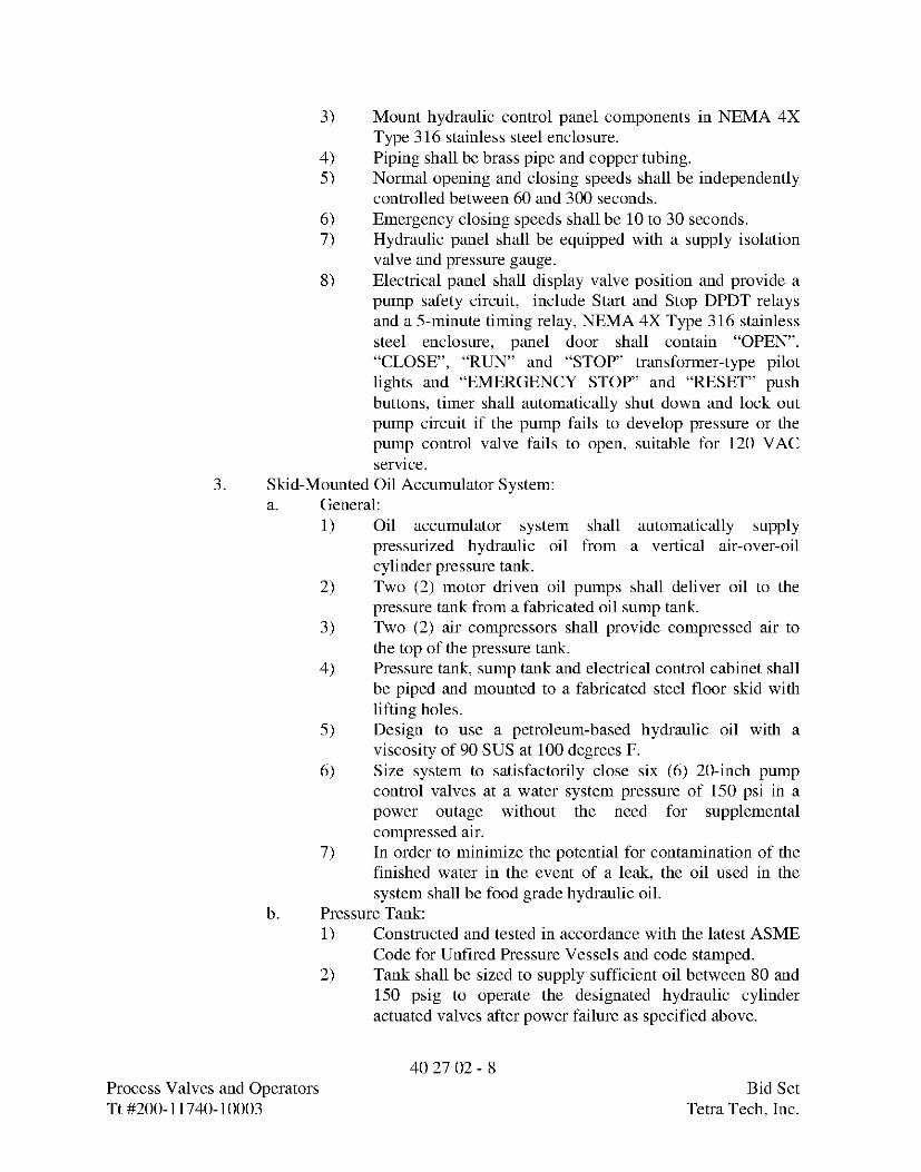
3) Mount hydraulic control panel components in NEMA 4XType 316 stainless steel enclosure.
4) Piping shall be brass pipe and copper tubing.5) Normal opening and closing speeds shall be independently
controlled between 60 and 300 seconds.6) Emergency closing speeds shall be 10 to 30 seconds.7) Hydraulic panel shall be equipped with a supply isolation
valve and pressure gauge.8) Electrical panel shall display valve position and provide a
pump safety circuit, include Start and Stop DPDT relaysand a 5-minute timing relay, NEMA 4X Type 316 stainlesssteel enclosure, panel door shall contain "OPEN","CLOSE", "RUN" and "STOP" transformer-type pilotlights and "EMERGENCY STOP" and "RESET" pushbuttons, timer shall automatically shut down and lock outpump circuit if the pump fails to develop pressure or thepump control valve fails to open, suitable for 120 VACservice.
3. Skid-Mounted Oil Accumulator System:a. General:
1) Oil accumulator system shall automatically supplypressurized hydraulic oil from a vertical air-over-oilcylinder pressure tank.
2) Two (2) motor driven oil pumps shall deliver oil to thepressure tank from a fabricated oil sump tank.
3) Two (2) air compressors shall provide compressed air tothe top of the pressure tank.
4) Pressure tank, sump tank and electrical control cabinet shallbe piped and mounted to a fabricated steel floor skid withlifting holes.
5) Design to use a petroleum-based hydraulic oil with aviscosity of 90 SUS at 100 degrees F.
6) Size system to satisfactorily close six (6) 20-inch pumpcontrol valves at a water system pressure of 150 psi in apower outage without the need for supplementalcompressed air.
7) In order to minimize the potential for contamination of thefinished water in the event of a leak, the oil used in thesystem shall be food grade hydraulic oil.
b. Pressure Tank:1) Constructed and tested in accordance with the latest ASME
Code for Unfired Pressure Vessels and code stamped.2) Tank shall be sized to supply sufficient oil between 80 and
150 psig to operate the designated hydraulic cylinderactuated valves after power failure as specified above.
40 27 02 - 8Process Valves and Operators Bid SetTt#200-11740-10003 Teka Tech,Inc.

c.
d.
e.
f.
g.
Process Valves and OperatorTt #200-11740-10003
3). Equip with a relief valve, level gauge, float switch, drain,and a cleanout hole.
Oil Pumps:1) Provide with relief valves, isolation valves, and suction
filters.2) Oil pumps shall be sized to pump the usable oil volume in
less than 15 minutes.Sump Tank: Sized to receive the oil stored in the pressure tank. Itshall be equipped with a level gauge, a low level float switch, adrain valve, and a screened fill cover.Compressors:1) Compressors shall be sized to recharge the pressure tank in
less than 15 minutes.2) Compressors shall be equipped with relief valves, isolation
valves, and an outlet filter with automatic drain.3) The oil accumulator skid shall include a refrigerated air
dryer system sized to accommodate the design air flowfrom both compressors. The dryer shall be designed todeliver compressed air with a pressure dew pointtemperature of 39 ° +/- 2° F and reheat the air temperature15-20°F below the inlet air temperature. The dryer shall bean air-cooled system with integral controls designed toprovide complete automatic operation of the system and itshall include an automated condensate drain system thatwill eject condensate. Particulate and coalescing air filtersshall also be furnished as part of the compressed air systemand shall be integral to the oil accumulator skid.
Piping:1) Piping between the hydraulic components shall be steel
pipe or tubing. Pneumatic piping shall be brass or copperpipe or tubing.
2) The piping shall include the necessary isolation valves,check valves, filters, and gauges sized to assure minimumpressure loss at the emergency cylinder flow rate.
3) The supply and drain connections shall be sized for amaximum fluid velocity of 8 feet per second at theemergency cylinder flow rate.
Electrical Panel and Controls:1) An electrical panel shall be provided to control the
operation of the oil pumps and air compressors inalternating lead/lag circuits and shall include a main circuitbreaker, motor circuit breakers, motor starters, a controltransformer, alarm reset button, Hand/Off/Automaticswitch, transformer-type pilot lights, plug-in control relayswith LED indication, terminal strip, 6 in. diameter pressuregauge, and control pressure switches.
40 27 02 - 9s Bid Set
Tetra Tech, Inc.

2) System shall be designed to operate on 460 volt, 3 phase,60 Hertz power.
3) Electrical controls shall automatically start the oil pumpswhen the pressure drops below 120 psig and stop the oilpumps when the proper oil level is reached. The controlsshall then start an air compressor if the pressure is below120 psig. The start and stop setpoints for the pumps andcompressors shall be field adjustable.
4) Alarm lights, contacts, and reset buttons shall be providedfor low oil level and low pressure conditions.
5) Panel shall be NEMA 12 control cabinet and constructed of14-gauge Type 316 stainless steel with Square-D Class9001 pilot lights and control switches.
6) Panel shall include appropriate input and output forinterface with the plant SCADA system as shown on theElectrical and Instrumentation Drawings. Signals toinclude the following dry contacts:�042In-Auto (Hand Switch set to Auto)�042System Active (power on and functioning, motors may
not be running)�042Oil Pump #1, Running�042Oil Pump #2, Running�042Air Compressor #1, Running�042Air Compressor #2, Running�042System Warning�042System Fault�042Low Oil Level�042Low PressureSignals to include the following analog (4-20 mA) outputs:�042Oil Pressure�042Air Pressure
h. Motors: Oil pump and air compressor motors shall of TEFC orODP construction.
D. Plug Valves:
1. Valves:a. Nonlubricated, 175 psi CWP, drip-tight shutoff in either direction,
cast iron body, welded nickel seats, cast iron plug with Buna-Nfacing, stainless steel or bronze bearings, flanged ends for exposedservice, mechanical joint ends for buried service. Ports shallprovide an unobstructed port area equal to at least 80 percent of thenominal pipe size cross sectional area. All valve castings shall bemanufactured in the United States.
b. Manufacturers:
40 27 02 - 10Process Valves and Operators Bid SetTt#200-11740-10003 Teka Tech,Inc.
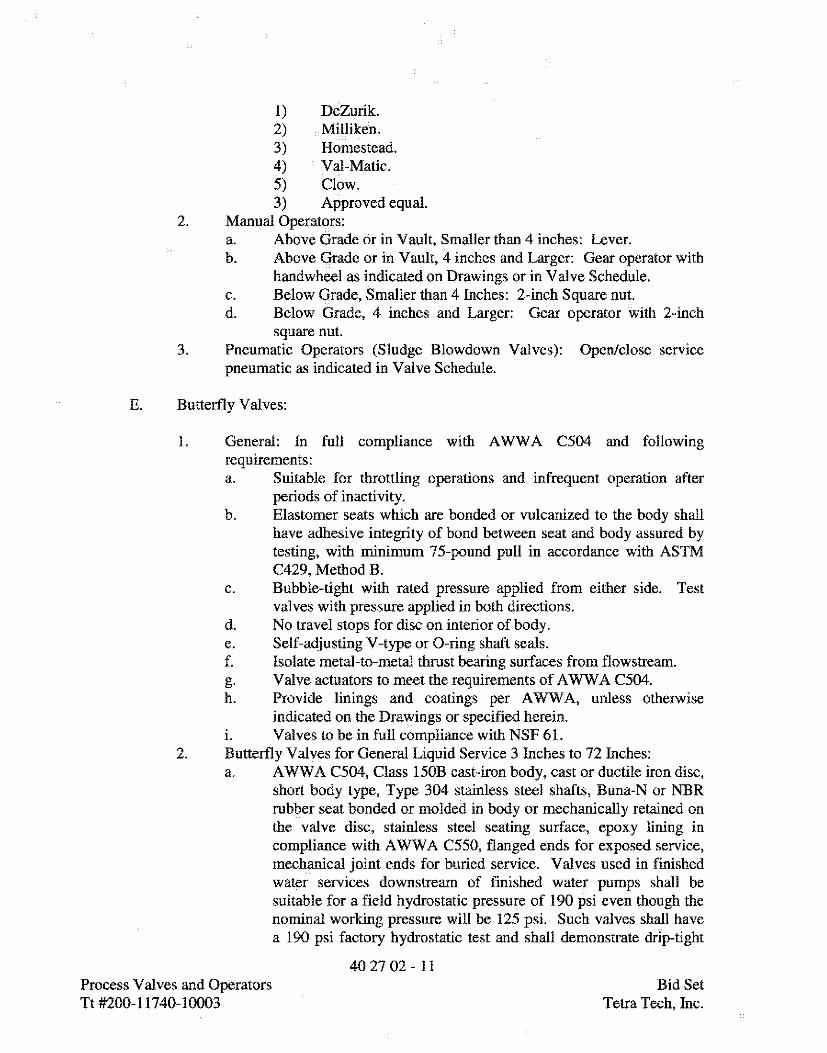
1) DeZurik.2) Milliken.3) Homestead.4) Val-Matic.5) Clow.3) Approved equal.
2. Manual Operators:a. Above Grade or in Vault, Smaller than 4 inches: Lever.b. Above Grade or in Vault, 4 inches and Larger: Gear operator with
handwheel as indicated on Drawings or in Valve Schedule.c. Below Grade, Smaller than 4 Inches: 2-inch Square nut.d. Below Grade, 4 inches and Larger: Gear operator with 2-inch
square nut.3. Pneumatic Operators (Sludge Blowdown Valves): Open/close service
pneumatic as indicated in Valve Schedule.
E. Butterfly Valves:
1. General: In full compliance with AWWA C504 and followingrequirements:a. Suitable for throttling operations and infrequent operation after
periods of inactivity,b. Elastomer seats which are bonded or vulcanized to the body shall
have adhesive integrity of bond between seat and body assured bytesting, with minimum 75-pound pull in accordance with ASTMC429, Method B.
c. Bubble-tight with rated pressure applied from either side. Testvalves with pressure applied in both directions.
d. No travel stops for disc on interior of body.e. Self-adjusting V-type or 0-ring shaft seals.f. Isolate metal-to-metal thrust bearing surfaces from flowstream.g. Valve actuators to meet the requirements of AWWA C504.h. Provide linings and coatings per AWWA, unless otherwise
indicated on the Drawings or specified herein.i. Valves to be in full compliance with NSF 6L
2. Butterfly Valves for General Liquid Service 3 Inches to 72 Inches:a. AWWA C504, Class 150B cast-iron body, cast or ductile iron disc,
short body type, Type 304 stainless steel shafts, Buna-N or NBRrubber seat bonded or molded in body or mechanically retained onthe valve disc, stainless steel seating surface, epoxy lining incompliance with AWWA C550, flanged ends for exposed service,mechanical joint ends for buried service. Valves used in finishedwater services downstream of finished water pumps shall besuitable for a field hydrostatic pressure of 190 psi even though thenominal working pressure will be 125 psi. Such valves shall havea 190 psi factory hydrostatic test and shall demonstrate drip-tight
40 27 02 - 11Process Valves and Operators Bid SetTt #200-11740-10003 Tetra Tech, Inc.

capability. All valve castings shall be manufactured in the UnitedStates.
b. Operators:1) Buried Manually Operated Valves: Provide gear operator
vvith 2-inch square operating nut.2) Exposed Manually Operated Valves: Provide gear operator
with handwheel as indicated on Drawings or in ValveSchedule.
3) Provide open/close or modulating pneumatic operatorswhere shown on Drawings or in Valve Schedule.
c. Manufacturers:1) DeZurik.2) Val-Matic,3) Mosser.4) Kennedy.
3. Butterfly Valves for Backwash Air Service:a. Cast iron body, cast or ductile iron disc, high-temperature seat,
rated for at least 200 degrees F, Type 304 stainless steel shaft.b. Operators:
1) Manually Operated Valves: Provide hand lever withlocking mechanism.
2) Pneumatically Actuated Valves: Provide open/closepneumatic actuators as shown on Drawings or in ValveSchedule.
c. Manufacturers:a. DeZurik.b. Tyco.c. Milliken.d. Approved equal from list in Paragraph 2.04 E 2 c.
4. PVC Butterfly Valves 1-1/2 Inches to 4 Inches for Chemical Service:a. Wafer body type, pressure rated 150 psi at 70 degrees F CWP,
solid ASTM D1784, Type I, Grade I polyvinyl chloride body andcontoured PVC or polypropylene valve disc, stainless steel valvestem, Viton seat, lever operator,
b. Manufacturers:1) ASAHI/America.2) Spears.3) Approved equal.
F. Check Valves:
1. Double Check Valve Backflow Prevention Assembly 3/4 Inch to 10Inches:a. Two resilient seated check valves, two nonrising stem resilient
seated isolation gate valves, test cocks, in accordance with AWWAC510, rated 175 psi maximum working pressure, compliant with
40 27 02 - 12Process Valves and Operators Bid SetTt #200-11740-10003 Tetra Tech, Inc.

requirements of USC Foundation For Cross-Connection Controland Hydraulic Research. Provide OS&Y gates for fire protectionapplication.
b. Manufacturers:1) FEBCO.2) Danfoss Flomatic.3) Watts.4) Approved equal.
2. Rubber Flapper Check Valves:a. Full body, 150 psi rating, cast or ductile iron body, rubber flapper
type design, flanged ends.b. Manufacturers:
1) Apco.2) Val-Matic.3) Milliken.4) GA Industries.5) Approved equal.
4. Cushioned Swing Check Valves:a. Wafer style, cast iron body, 150 psi rating, Type 316 stainless steel
disc, Buna-N seal, outside lever & weight, air cushioning dashpot.b. Manufacturers:
1) Tyco/Prince.2) KF Valves.3) Approved equal.
5. PVC Ball Check Valves:a. ASTM D1784 Type I Grade I polyvinyl chloride body, double
union solvent weld or threaded socket ends, elastomer seat suitablefor intended service.
b. Manufacturers:1) Nibco, Chemtrol.2) ASAHI/American.3) Spears.4) Approved equal.
G. Self-Regulated Automatic Valves:
1. Combination Air/Vacuum Release Valves 4 Inches to 16 Inches:a. Equipped with anti-slam device to throttle flow of water into air
valve. Design anti-slam device to permit full, unrestricted flow ofair into and out of air valve but reduce flow area for water toapproximately 10 percent.
b. Rated 150 psi working pressure, cast-iron or ductile iron body andcover, stainless steel float and trim, built and tested to AWWAC512, ASME B16.1 Class 125 flanged inlet and plain outlet withprotective hood.
40 27 02 - 13Process Valves and Operators Bid SetTt#200-11740-10003 Teka Tech,Inc.

c. Provide air release valve and isolation gate valve to meet ratedworking pressure.
d. Valve shall release air during pipeline filling, admit air duringpipeline draining, and release small pockets of air underpressurized operation.
e. Manufacturers:1) A.R.I.2) Val-Matic.3) Apco.4) Approved equal.
2. Vertical Turbine Pump Air Release Valves:a. Equip with anti-slam device and throttling provisions.b. Cast-iron or ductile iron body and cover, stainless steel float and
trim, built and tested to AWWA C512, ASME B16.1 Class 125flanged or threaded inlet as indicated on the Drawings or in theValve Schedule.1) Raw Water Pump Application: 150 psi minimum pressure
rating.2) Finished Water Pump Application: 250 psi minimum
pressure rating.c. Provide air release valve and isolation gate valve to meet rated
working pressure.d. Valve shall release air during pump startup and admit air after
pump shutdown.e. Manufacturers:
1) A.R.I.2) Val-Matic.3) Apco.4) Approved equal.
3. Pressure Relief and Surge Anticipator Valvesa. Designed to control high pressures resulting from power failure
surges via bypassing system pressure that exceeds the highpressure control setting by opening a preset amount when sensedpressure decreases below a preset minimum in anticipation of asurge.
b. Rated 250 psi working pressure, ductile iron body in accordancewith ASTM A536, ANSI B16.42 Class 150 flanged inlet andoutlet.
c. Manufacturers:1) CLA-VAL.2) Bermad.3) OCV.4) Ross Valve.5) Singer.6) Approved equal.
40 27 02 - 14Process Valves and Operators Bid SetTt#200-11740-10003 Teka Tech,Inc.
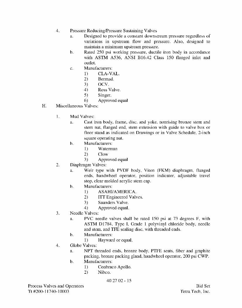
4. Pressure Reducing/Pressure Sustaining Valvesa. Designed to provide a constant downstream pressure regardless of
variations in upstream flow and pressure. Also, designed tomaintain a minimum upstream pressure.
b. Rated 250 psi working pressure, ductile iron body in accordancewith ASTM A536, ANSI B16.42 Class 150 flanged inlet andoutlet.
c. Manufacturers:1) CLA-VAL.2) Bermad.3) OCV.4) Ross Valve.5) Singer.6) Approved equal
H. Miscellaneous Valves:
1. Mud Valves:a. Cast iron body, frame, disc, and yoke, nonrising bronze stem and
stem nut, flanged end, stem extension with guide to valve box orfloor stand as indicated on Drawings or in Valve Schedule, 2-inchsquare operating nut.
b. Manufacturers:1) Waterman2) Clow3) Approved equal
2. Diaphragm Valves:a. Weir type with PVDF body, Viton (FKM) diaphragm, flanged
ends, handwheel operator, position indicator, adjustable travelstop, clear molded acrylic stem cap.
b. Manufacturers:1) ASAHI/AMERICA.2) ITT Engineered Valves.3) Saunders Valve.4) Approved equal.
3. Needle Valves:a. PVC needle valves shall be rated 150 psi at 73 degrees F, with
ASTM D1784, Type I, Grade 1 polyvinyl chloride body, needleand stem, and TFE sealing disc, with threaded ends.
b. Manufacturers:1) Hayward or equal.
4. Globe Valves:a. NPT threaded ends, bronze body, PTFE seats, fiber and graphite
packing, bronze packing gland, handwheel operator, 200 psi CWP.b. Manufacturers:
1) Conbraco Apollo.2) Nibco.
40 27 02 - 15Process Valves and Operators Bid SetTt#200-11740-10003 Teka Tech,Inc.

3) Approved equal.5. Solenoid Valves:
a. NPT threaded ends, 150 psi pressure rating, brass body, power toopen (normally closed), designed for operation on 120 VACpower.
b. Manufacturers:1) ASCO.2) Approved equal.
2.05 OPERATORS AND ACTUATORS
A. Manual Operators:
1. General: For AWWA valves, operator force shall not exceed therequirements of the applicable valve standard. For non-AWWA valves,operator force not to exceed applicable industry standard or 80 pounds,whichever is less, under any operating condition, including initialbreakaway. Provide gear reduction operator to meet these requirements
2. Exposed Operators:a. Handwheels: Galvanized and painted.b. Levers: Provide with locking mechanism unless otherwise
specified.c. Provide chain wheel and guide with tieback, extension stem, floor
stand, and other accessories as required to permit operation fromnormal operation level as specified herein.
d. Valve handles shall accept a padlock, and wheels a chain andpadlock.
3. Chain Wheels and Guides:a. Provide chain wheel and guide assemblies or chain lever
assemblies on manually operated valves over 6 feet 9 inches abovefinish floor.
b. Chains shall be installed to within 3 feet 0 inch of finish floor.c. Where chains hang in normally traveled areas, provide appropriate
"L" type tie-back anchors.d. Chains shall be installed to within operator horizontal reach of 2
feet 6 inches maximum, measured from normal operator standinglocation or station.
4. Buried Operators:a. Buried service operators on valves larger than 2-1/2 inches shall
have a 2-inch AWWA operating nut. Buried operators on valves 2inches and smaller shall have cross handle for operation by forkedkey. Enclose moving parts of valve and operator in housing toprevent contact with the soil.
b. Design buried service operators for quarter-turn valves towithstand 450 foot-pounds of input torque at the FULLY OPEN or
40 27 02 - 16Process Valves and Operators Bid SetTt#200-11740-10003 Teka Tech,Inc.
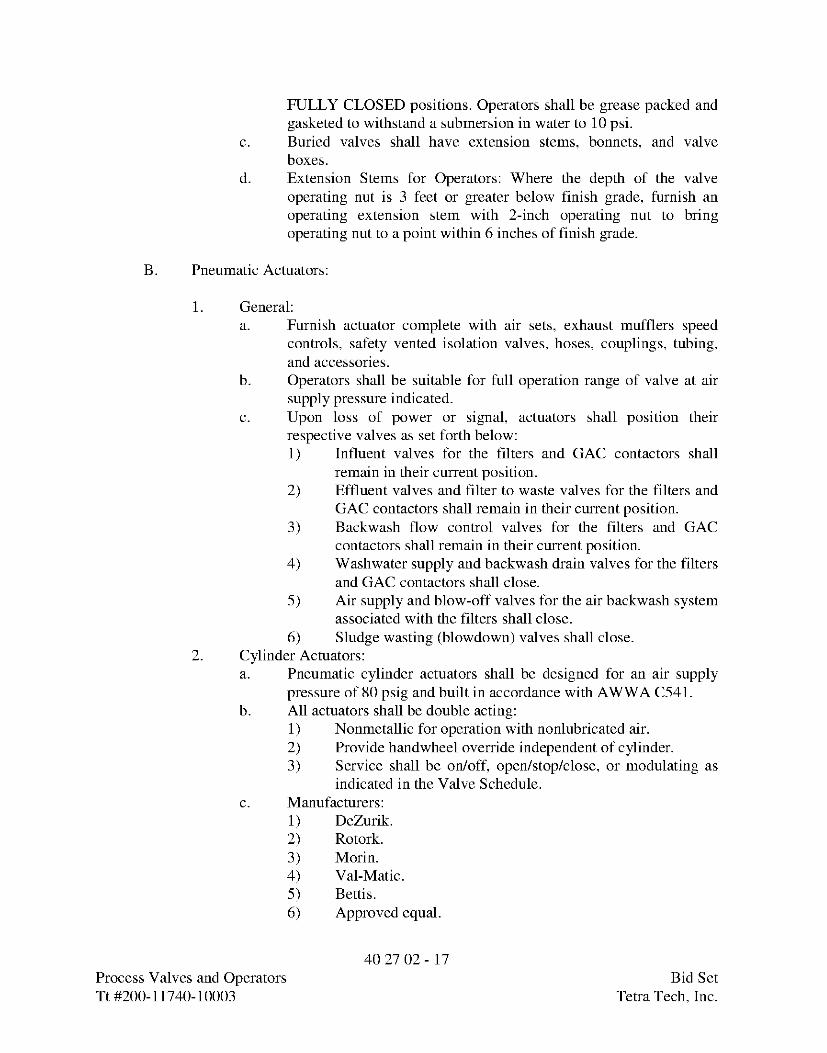
FULLY CLOSED positions. Operators shall be grease packed andgasketed to withstand a submersion in water to 10 psi.
c. Buried valves shall have extension stems, bonnets, and valveboxes.
d. Extension Stems for Operators: Where the depth of the valveoperating nut is 3 feet or greater below finish grade, furnish anoperating extension stem with 2-inch operating nut to bringoperating nut to a point within 6 inches of finish grade.
B. Pneumatic Actuators:
1. General:a. Furnish actuator complete with air sets, exhaust mufflers speed
controls, safety vented isolation valves, hoses, couplings, tubing,and accessories.
b. Operators shall be suitable for full operation range of valve at airsupply pressure indicated.
c. Upon loss of power or signal, actuators shall position theirrespective valves as set forth below:1) Influent valves for the filters and GAC contactors shall
remain in their current position.2) Effluent valves and filter to waste valves for the filters and
GAC contactors shall remain in their current position.3) Backwash flow control valves for the filters and GAC
contactors shall remain in their current position.4) Washwater supply and backwash drain valves for the filters
and GAC contactors shall close.5) Air supply and blow-off valves for the air backwash system
associated with the filters shall close.6) Sludge wasting (blowdown) valves shall close.
2. Cylinder Actuators:a. Pneumatic cylinder actuators shall be designed for an air supply
pressure of 80 psig and built in accordance with AWWA C541.b. All actuators shall be double acting:
1) Nonmetallic for operation with nonlubricated air.2) Provide handwheel override independent of cylinder.3) Service shall be on/off, open/stop/close, or modulating as
indicated in the Valve Schedule.c. Manufacturers:
1) DeZurik.2) Rotork.3) Morin.4) Val-Matic.5) Bettis.6) Approved equal.
40 27 02 - 17Process Valves and Operators Bid SetTt#200-11740-10003 Teka Tech,Inc.
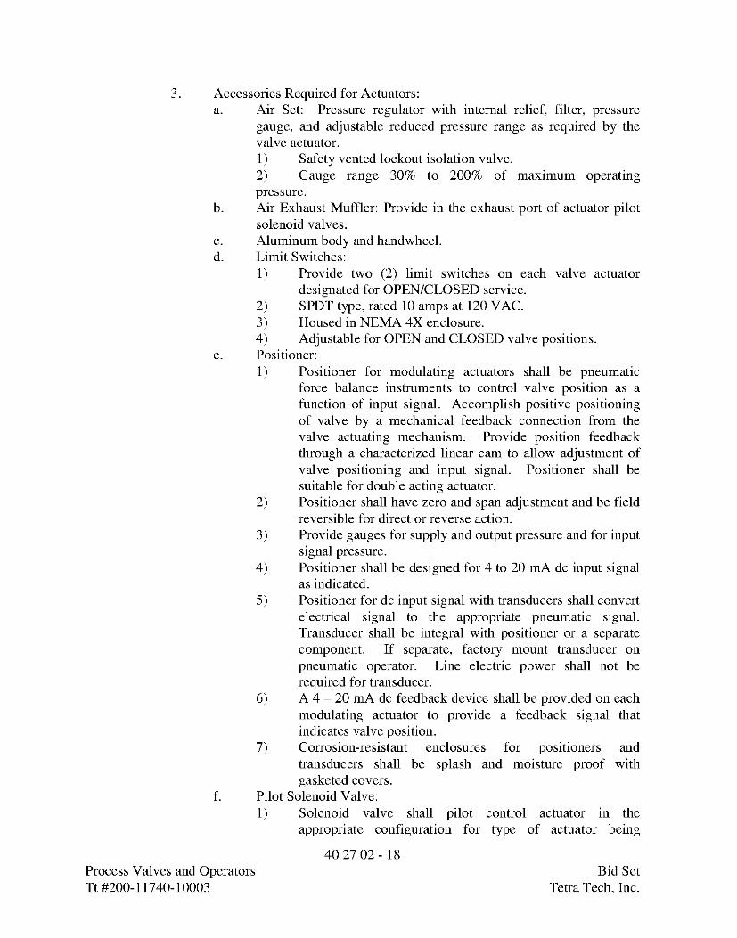
3. Accessories Required for Actuators:a. Air Set: Pressure regulator with internal relief, filter, pressure
gauge, and adjustable reduced pressure range as required by thevalve actuator.1) Safety vented lockout isolation valve.2) Gauge range 30% to 200% of maximum operatingpressure.
b. Air Exhaust Muffler: Provide in the exhaust port of actuator pilotsolenoid valves.
c. Aluminum body and handwheel.d. Limit Switches:
1) Provide two (2) limit switches on each valve actuatordesignated for OPEN/CLOSED service.
2) SPDT type, rated 10 amps at 120 VAC.3) Housed in NEMA 4X enclosure.4) Adjustable for OPEN and CLOSED valve positions.
e. Positioner:1) Positioner for modulating actuators shall be pneumatic
force balance instruments to control valve position as afunction of input signal. Accomplish positive positioningof valve by a mechanical feedback connection from thevalve actuating mechanism. Provide position feedbackthrough a characterized linear cam to allow adjustment ofvalve positioning and input signal. Positioner shall besuitable for double acting actuator.
2) Positioner shall have zero and span adjustment and be fieldreversible for direct or reverse action.
3) Provide gauges for supply and output pressure and for inputsignal pressure.
4) Positioner shall be designed for 4 to 20 mA de input signalas indicated.
5) Positioner for de input signal with transducers shall convertelectrical signal to the appropriate pneumatic signal.Transducer shall be integral with positioner or a separatecomponent. If separate, factory mount transducer onpneumatic operator. Line electric power shall not berequired for transducer.
6) A 4 - 20 mA de feedback device shall be provided on eachmodulating actuator to provide a feedback signal thatindicates valve position.
7) Corrosion-resistant enclosures for positioners andtransducers shall be splash and moisture proof withgasketed covers.
f. Pilot Solenoid Valve:1) Solenoid valve shall pilot control actuator in the
appropriate configuration for type of actuator being
4027 02- 18Process Valves and Operators Bid SetTt#200-11740-10003 Teka Tech,Inc.
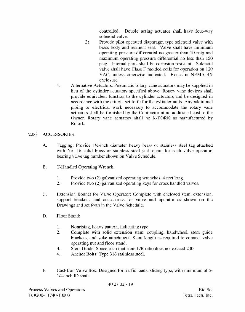
controlled. Double acting actuator shall have four-waysolenoid valve.
2) Provide pilot operated diaphragm type solenoid valve withbrass body and resilient seat. Valve shall have minimumoperating pressure differential no greater than 10 psig andmaximum operating pressure differential no less than 150psig. Internal parts shall be corrosion-resistant. Solenoidvalve shall have Class F molded coils for operation on 120VAC, unless otherwise indicated. House in NEMA 4Xenclosure.
4. Alternative Actuators: Pneumatic rotary vane actuators may be supplied inlieu of the cylinder actuators specified above. Rotary vane devices shallprovide equivalent function to the cylinder actuators and be designed inaccordance with the criteria set forth for the cylinder units. Any additionalpiping or electrical work necessary to accommodate the rotary vaneactuators shall be furnished by the Contractor at no additional cost to theOwner. Rotary vane actuators shall be K-TORK as manufactured byRotork.
2.06 ACCESSORIES
A. Tagging: Provide 1½-inch diameter heavy brass or stainless steel tag attachedwith No. 16 solid brass or stainless steel jack chain for each valve operator,bearing valve tag number shown on Valve Schedule.
B. T-Handled Operating Wrench:
1. Provide two (2) galvanized operating wrenches, 4 feet long.2. Provide two (2) galvanized operating keys for cross handled valves.
C. Extension Bonnet for Valve Operator: Complete with enclosed stem, extension,support brackets, and accessories for valve and operator as shown on theDrawings and set forth in the Valve Schedule.
D. Floor Stand:
1. Nonrising, heavy pattern, indicating type.2. Complete with solid extension stem, coupling, handwheel, stem guide
brackets, and yoke attachment. Stem length as required to connect valveoperating nut and floor stand.
3. Stem Guide: Space such that stem L/R ratio does not exceed 200.4. Anchor Bolts: Type 316 stainless steel.
E. Cast-Iron Valve Box: Designed for traffic loads, sliding type, with minimum of 5-1/4-inch ID shaft.
40 27 02 - 19Process Valves and Operators Bid SetTt#200-11740-10003 Teka Tech,Inc.

1. Box: Cast iron with minimum depth of 9 inches.2. Lid: Cast iron, minimum depth 3 inches, nonlocking type, marked to
indicate service.3. Extensions: Cast iron.4. Two-piece box and lid for valves 4 inches through 12 inches, three-piece
box and lid for valves larger than 12 inches with base sized for valve.5. Valve extension stem for valves with operating nuts 3 feet or greater
below finish grade.
PART 3 EXECUTION
3.01 INSTALLATION
A. General: Install valves, manual operators, pneumatic and hydraulic actuators, andrelated equipment in accordance with the manufacturer's recommendations.
B. Flanged Ends:
1. Flanged valve bolt holes shall straddle vertical centerline of pipe.2. Clean flanged faces, insert gasket and bolts, and tighten nuts progressively
and uniformly.
C. Screwed Ends:
1. Clean threads by wire brushing or swabbing.2. Apply joint compound.
D. Solvent Weld PVC Valves: Install using solvents approved for valve serviceconditions.
E. Valve Installation and Orientation:
1. General:a. Install valves so handles operate from fully open to fully closed
without encountering obstructions.b. Install valves in location for easy access for routine operation and
maintenance.c. Install valves per manufacturer's recommendations.
2. Gate, Globe, and Ball Valves:a. Install operating stem vertical when valve is installed in horizontal
runs of pipe having centerline elevations 4 feet 6 inches or lessabove finished floor, unless otherwise shown.
40 27 02 - 20Process Valves and Operators Bid SetTt#200-11740-10003 Teka Tech,Inc.

b. Install operating stem horizontal in horizontal runs of pipe havingcenterline elevations greater than 4 feet 6 inches above finish floor,unless otherwise shown.
3. Butterfly Valves:a. When butterfly valve actuation will result in the disc being in
conflict with adjacent valves, fittings, or equipment provide spoolpieces to resolve conflicts and maintain proper clearances.
b. When installed immediately downstream of a swing check valve,install valve with shaft perpendicular to swing check shaft.
c. For free inlet or discharge into basins and tanks, install valve withshaft in vertical position.
4. Check Valves:a. Install valve in horizontal piping only for liquid services.b. Install valve in horizontal or vertical flow (up) piping for gas
services.c. Install swing check valve with shaft in horizontal position.
F. Install safety isolation valves on compressed air lines.
G. Locate valve to provide accessibility for control and maintenance. Install accessdoors in finished walls and plaster ceilings for valve access when necessary.
H. Torque Tube: Where operator for quarter-turn valve is located on floor stand,furnish extension stem torque tube of a type properly sized for maximum torquecapacity of valve.
3.02 TESTS AND INSPECTION
A. Valves may be either tested while testing pipelines, or as a separate step.
B. Test that valves open and close smoothly under operating pressure conditions.Demonstrate that two-way valves open and close smoothly under operatingpressure conditions from both directions.
C. Inspect air and vacuum valves as pipe is being filled to verify venting and seatingis fully functional.
D. Count and record number of turns to open and close valve; account for anydiscrepancies with manufacturer's data.
E Set, verify, and record set pressures for relief and regulating valves.
F. Automatic valves to be tested in conjunction with control system testing. Setopening and closing speeds, limit switches, as required or recommended byEngineer.
40 27 02 - 21Process Valves and Operators Bid SetTt#200-11740-10003 Teka Tech,Inc.

G. Test hydrostatic relief valve seating; record leakage. Adjust and retest tomaximum leakage of 0.1 gpm per foot of seat periphery.
3.03 MANUFACTURER'S SERVICES
A. The valve(s) as listed below require manufacturer's field services:
1. Combination Air/Vacuum Release Valves.2. Pressure Relief and Surge Anticipator Valves.3. Pressure Reducing Valves4. Finished Water Pump Control Valves.5. Pneumatically Actuated Valves
B. Manufacturer's Representative: Present at site for minimum number of days listedbelow, travel time excluded:
1. One (1) for each type of valve listed above except for pneumaticallyactuated butterfly valves.
2. Five (5) days for pneumatically actuated butterfly valves.
C. See Section 01 43 33, Manufacturers' Field Services, and Section 01 91 14,Equipment Testing and Facility Startup.
3.04 SUPPLEMENTS
A. The supplements listed below, following "End of Section", are part of thisSpecification.
1. Valve Schedule.
END OF SECTION
40 27 02 - 22Process Valves and Operators Bid SetTt#200-11740-10003 Teka Tech,Inc.

Valv
eS
ched
ule
(Pro
cess
Vel
ves
3"&
Larg
er-
Exc
ludi
ngC
hem
ical
Feed
Com
pres
sed
Air.
Plu
mbi
ng,F
ireP
mie
ctio
n&
Fuel
Sys
tem
Val
ves)
Non
sien
]O
pera
ting
End
Va
lve
Nù
mb
er
Genera
1Loca
tionáE
nvi
ronm
ent
Ser
vice
Va
lve
Siz
eV
alv
eT
ype
Pre
ssur
eC
onne
ctio
nsA
ctuata
rR
emar
ks
Val
ves
Ass
ocia
ted
with
Raw
Wat
erIn
take
Pum
pS
tatio
n
10(V
-IA
RW
Inta
keP
ump
Roo
m/A
bove
Gra
de
/In
do
cqR
awW
ater
16"
70ps
iFl
ange
dN
/AD
ashp
otPu
mp
No.
lA
10-C
V-2
AR
WIn
take
Ptu
npR
oom
/Abo
veG
ale/
Indo
ors
Raw
Wat
er20
"70
psi
Ng
ed
N/A
Das
hpot
Pum
pN
o.2A
10
�2
54
V4
BR
WIn
take
Pum
pR
oonV
Abo
veG
rade
/Indo
ors
Raw
Wat
er16
"C
heck
,Waf
erS
tyle
w/
70ps
iFl
ange
dN
/AC
ushi
oned
Waf
erC
heck
Val
vefo
rRaw
Wat
er|
Das
hput
Pum
pN
o.3B
10-B
FV
-1A
4R
WIn
take
Pum
pRoo
m/A
bovc
Gra
dc/In
door
sR
awW
ater
16"
But
terf
ly70
psi
Flan
ged
Man
uaV
Gea
r/lla
ndw
hee
Isol
atio
nVal
vefo
rRaw
Wat
erP
umpN
o.lA
10-B
FV-1
A-2
RW
Inta
keC
ham
ber/S
ubm
erge
dR
awW
ater
16"
But
terf
ly70
psi
hg
ed
Surg
eA
ntic
ipat
orD
isch
arge
toIn
take
Cha
mbe
r1
10-B
FV-1
B..2
RW
Inta
keC
ham
ber/S
ubm
erge
dR
awW
ater
16"
But
terf
ly70
psi
Ng
ed
Surg
eA
ntic
ipat
orD
isch
arge
toIn
take
Cha
mbe
r1
10-B
FV
-2A
-1R
WIn
take
Pum
pR
oora
/Abo
veG
rade
/Indo
ors:
Raw
Wat
er20
"B
utte
sfly
70ps
iFl
ange
dM
anua
VG
ear/
Han
dwhe
eIs
olat
ion
Val
vefo
rRaw
Wat
erP
ump
No.
2A
10-B
FV-2
A-2
RW
Inta
keC
ham
ber/S
ubm
erge
dR
awW
ater
16"
But
terf
ly70
psi
Ng
ed
Serg
eA
ntic
ipat
orD
isch
arge
toIn
take
Cha
mbe
r2
10-B
FV-2
B-2
RW
inta
keC
ham
ber/S
ubm
erge
dR
awW
ater
16"
But
terB
y70
psi
Fian
ged
Surg
eA
ntic
ipat
orD
isch
arge
tolu
take
Cha
mbe
r2
10-B
FV-3
B-1
RW
Inta
kePu
mp
Roo
nvA
bove
Gau
de/in
door
sR
awW
ater
16"
But
terf
ly70
psi
Flan
ged
Man
um/G
ear/H
andw
heel
Isol
atio
nV
alve
for
Raw
Wat
erPu
mp
No,
3B
14
BF
V-3
A-2
RW
Inta
keC
ham
ber/
Sub
mer
ged
Raw
Wat
er16
"B
utterf
ly7
0p
siM
ange
dM
anua
/E
xten
sion
Su
rge
An
ticip
ato
rDis
cha
rge
toln
take
Ch
am
be
r3
10..B
FV-3
B-2
RW
Inta
keC
ham
ber/S
ubm
erge
dR
awW
ater
16"
But
terf
ly70
psi
Ran
ged
2.Su
rge
Ant
icip
ator
Dis
char
geto
Inta
keC
ham
ber3
10-B
FV
4R
WIn
lake
Pum
pR
oom
/Abo
veG
rade
/|ndo
ora
Raw
Wat
er42
"B
utte
rfly
70ps
iEh
inge
dM
anua
l/Gea
r/hd
whe
elIs
olat
ion
Val
vefo
r42"
Dis
char
geM
anifa
ld
10-B
FV
-5R
WIn
take
Pum
pR
oom
/Abo
veG
rade
/Indo
ors
Raw
Wat
er42
"B
utterf
ly70
psi
Ran
ged
Man
ual/G
ear/
Han
dwhe
elIs
olat
ion
valv
efo
r42
"D
isch
arge
Ma
nifo
ld
10..B
FV-6
RW
Inta
kePu
mp
Roo
m/A
bove
Gra
de/In
door
sR
awW
ater
16"
But
terf
ly70
psi
Flan
ged
Man
ual/G
ear/H
andw
heel
Isol
atio
nva
lve
forS
urge
Ant
icip
ator
Val
ve
10-P
RV-
1R
WIn
take
Pum
pR
oom
/Abo
veG
rade
/ludo
ors
Raw
Wat
er16
"Su
rge
Ant
icip
ator
70ps
iFi
snge
dN
/ASu
rge
Ant
icip
ator
Vai
ve
10-A
RV
-1A
RW
Inta
keP
ump
Roo
m/A
bove
Gra
de/In
door
sR
awW
ater
3"70
psi
Flan
ged
Rel
ease
Val
ve)
No.
IA
10-A
RV
-2A
RW
luts
keP
ump
Roo
m/A
bove
Gra
de/In
door
sR
awW
ater
6"
70ps
iFl
ange
dM
an
al/L
em
(For
Isol
atio
sW
eliP
mnp
Air
Re
lme
Vol
vefo
rR
awW
ater
Pum
pR
elea
seV
alve
)N
o.2
A
10-A
RV
-3B
RW
Inía
kePu
mp
Roo
m/A
bove
Gra
de/In
door
sR
awW
ater
3"70
pai
Flan
ged
Mä
nva
l/Le
w(F
®Is
olat
ion
Wel
lPm
pA
irR
elea
seV
alve
for
Raw
Wat
erP
ep
Rel
ease
Val
ve)
No.3
B
1G-A
RV
..4R
WIn
take
Pum
pR
oom
/Abo
veG
rade
/Indo
ors
Raw
Wat
er6"
70ps
iFl
ange
dR
elea
se2s
olat
ion
Val
ve)
Man
ifold
,P
row
de6"
Gat
eV
alve
for
Isol
atio
n
10-A
RV
-5R
WIn
take
Pum
pR
oom
/Abo
veG
rade
/Indo
ors
Raw
Wat
er6"
Com
bina
tion
Air
70ps
iFl
ange
dR
elea
sei
Isol
atio
nV
alve
jM
anifo
ld,
Pro
vide
6"G
ate
Val
vefo
rIso
latíe
n

Val
veS
ched
ule
(Pro
cess
Val
ves
3"&
Larg
er-
Exc
ludi
ngC
hem
ical
Feed
,Com
pres
sed
Air,
Plu
mbi
ríg,
Fire
Pra
teet
ion
&F
uelS
yste
etV
alve
s)
Nom
inal
Opera
ting
End
Val
veN
ùmbe
rG
enera
lLoca
tionáE
nvi
ronm
ent
Ser
vice
Val
veS
ize
Val
veT
ype
Pre
ssur
eC
onne
ctio
neA
ctua
dor
Ret
nark
s
Val
ves
Ass
ocia
ted
with
Mix
ing,
Flo
ccul
atio
n.ä
Sed
imen
tatia
nF
acili
ties
Ups
tream
ofR
awW
ater
Sta
ticM
ixer
/Abo
ve20
-BFV
-1G
rade
/Out
door
sR
aw
Wah
Bu
Mps
iR
ange
dM
anua
l/Gea
rN
A
Dow
nstre
amo
fRaw
Wat
erSt
atic
20-B
FV-2
Mim
/hW
Me
Raw
Wat
er30
"B
utte
rfly
10ps
iFl
ange
dM
anua
l/Gea
r/Han
dwhe
elN
/A
20-P
V-!
Aor
thEn
do
fFlo
cN
o.1/
Insi
deU
nthi
cken
edSl
udge
4"P
lug
10ps
iFl
ange
dP
neum
atic
-Ope
n/C
lose
20..P
V4B
Nor
thE
ndofF
loc
Bas
inN
o.l/I
nsid
eU
end
Slu
dy
4"
Plg
Mp
id
N-
hP
ossi
ble
Vai
veS
ubm
erge
nëe,
Ext
ensi
onB
onne
tfor
Blo
wdo
wn
Box
/Out
door
sO
pera
tor
20
-PV
-iC
Wes
tE
ndofF
loc
Bas
inN
o.1/
Bur
ied
Raw
Wat
er/U
nthi
cken
edS
ludg
e12
"P
lug
10ps
iM
echa
nica
lJoi
ntF
locc
ulat
ion/
Sed
imen
tatio
nB
asm
No.
ID
rain
20-P
V-2
AU
nthi
cken
edSl
udge
4"P
lug
10ps
iFl
ange
dP
neum
atic
-Ope
n/C
lose
Blo
wdo
wn
Box
/Out
door
sO
pera
int
Nor
thE
ndofF
loc
Bas
inN
o.2/
insi
deU
nthi
cken
edS
ludg
e4"
Plu
g10
psi
Flan
ged
Pne
umat
ic-
Ope
n/C
icsc
*B
low
dow
nB
ox/O
utdo
ors
Ope
rato
r
20-P
V-2
CW
estE
ndo
fFla
cB
asin
No.
2iB
urie
dR
awW
ater
/Unt
hick
ened
Slud
ge12
"P
lug
10ps
iM
echa
nica
!Jo
int
Mac
cula
tion/
Sed
imen
tatio
nB
asin
No.
2D
rain
2r».
PV
-3N
orth
east
Cor
nero
fFlo
cB
asin
No.
1/B
urie
dR
awW
ater
/Unt
hick
ened
Slu
dge
12"
Plu
g10
psi
Mec
hani
calJ
oint
Nut
/Val
veB
oxor
Spt
Back
was
hW
ater
Tank
20-P
V-4
Nor
thea
stC
orne
rofF
lue
Bas
inN
o.1/
Bur
ied
Raw
Wat
er/U
nthi
cken
edS
ludg
e12
"P
lug
10ps
iM
echa
nica
lJoi
nten
ns
wtoN
er
Nut
/Val
veB
oxcr
Spe
ntBa
ckw
ash
Wat
erTa
nk
20..P
V-5
Nor
thea
stC
omer
ofFl
ocB
asin
No.
1/B
urie
dR
awW
ater
/Unt
hick
ened
Slud
ge12
"P
lug
10ps
iM
echa
nica
lJoi
ntM
anua
l/Gea
r/2"
Ope
ratin
gD
inin
Div
ersi
onV
alve
-D
irect
sFl
owto
Thic
kcoe
rN
ut/V
alve
Box
erS
pent
Bac
kwas
hW
ater
Tan
k
20-M
UV
-1A
Wes
tEnd
ofF
loc
Bas
inN
o.1/
Subm
erge
dR
awW
ater
/Unt
hick
ened
Slud
ge12
"M
ud10
psi
Fisn
ged
Floc
cula
tion
Bas
inN
o.1
Wes
tDra
in
20-M
UV
-1B
Eas
tEnd
ofF
locB
asin
No.
1/S
ubm
erge
dR
awW
ater
/Unt
hick
ened
Slu
dge
12"
Mud
10ps
iFl
ange
d,
Flo
ccul
atio
nBas
inN
o.lE
sstD
rain
20-M
UV
-1C
Wes
tE
ndofS
cdB
asin
No.
l/Sub
mer
ged
Raw
Wat
er/U
nthi
cken
edS
ludg
e12
"M
ud10
psi
Flan
ged
Sed
imen
tatio
nB
asin
No.
1W
est
Dra
in
20
-MU
V-2
AW
est
End
ofM
acB
asin
No.
2/S
ubm
erge
dR
awW
ater
/Unt
hick
ened
Slu
dge
ifM
ud10
psi
Ean
ged
HEF
loc
Bas
inN
o.2
Wes
tD
rain
20-M
UV
-28
PAst
End
ofF
loc
Bas
inN
o.2/
Subm
erge
4iR
awW
ater
/Unt
hick
ened
Shad
ge12
"M
ud10
psi
Flan
ged
Floc
cula
tion
Bas
inN
o.2
East
Dra
in
20-M
UV
-2C
Wes
tE
ndofS
edB
asin
No.
2/S
ubm
erge
dR
awW
ater
/Unt
hick
ened
Slu
dge
12"
Mud
10ps
iE
ange
d,
Sed
imen
tatio
nB
asin
No.
2W
est
Dra
in
Val
ves
Ass
ocia
ted
with
Con
vent
iona
lF
iltra
ties
Fac
ilitie
s
21-B
FV
-1A
.S
ett!c
dWat
er36
"B
utte
rfly
5psi
Man
ged
Pne
mna
tic-O
pen/
Clo
seC
anne
l/Sub
mer
ged/
Out
door
sO
pera
tor
21-B
FV
-2A
Settl
edW
ater
36'
But
terf
ly5
psi
Man
ged
Pne
umat
ic-
Ope
n/C
lose
Cha
nnel
/Sub
mer
ged/
Out
door
aC
erat
or
21-B
FV-3
ASe
ttled
Wat
er36
"B
utte
rfly
5ps
iFl
ange
dP
neum
atic
-Ope
n/C
lose
Cha
nnel
/Sub
mer
gedi
Out
door
sO
pera
tor

Valv
eS
ched
ule
(Pro
cess
Val
ves
3"&
Larg
er-
Exc
ludi
ngC
hem
ical
Feed
,Com
pres
sed
Air,P
lùm
bing
,F
ireP
rote
ctio
n&
Fue
lSys
tem
Val
ves)
Nom
inal
Opera
ting
En
d½
lveN
um
ber
Ge
ne
rallo
catio
nà
En
viro
nm
en
tS
ervi
ceV
alve
Siz
eV
elve
Typ
eP
ress
ure
Con
nect
ions
Act
uato
rR
emar
ks
21-B
FV
4A
.S
ettle
dW
ater
36"
Butterf
ly5
psi
Flan
ged
Pne
urna
tic-
Ope
n/C
lose
erge
dM
eM
mxhon
NC
hann
el/S
ubm
erge
d/O
utdo
ots
oper
ator
2l-B
FV
-1B
Filte
rPi
peG
alle
ry/A
bove
Gra
de/in
door
sFi
nish
edW
ater
36"
But
terf
ly40
psi
Flan
ged
Pne
tana
tier
Ope
n/C
lose
Fihe
rNo.
1W
ash
Wat
erS
uppl
yV
alve
2l-B
FV
-2B
|Filt
erPi
peG
alle
ry/A
bove
Gra
de/In
door
sFi
nish
edW
ater
36"
But
terf
ly40
psi
Flan
ged
Pne
umat
ic-
Ope
n/C
lose
Filte
rN
o.2
Was
hW
ater
Sup
ply
Val
ve
2l-B
F¼
3B|F
ilter
Pipe
Gau
ery/
Aba
veG
rade
/indo
ors
Fini
hed
Wat
er36
"B
utte
rfly
40ps
iFl
ange
dP
neum
atic
-Ope
n/C
lose
Filte
rN
o.3
Was
hW
ater
Sup
ply
Val
ve
2l-B
F¼
4B|F
ilter
Pipe
Gal
lery
/Abo
veG
rade
/Indo
ors
Fini
shed
Wat
er36
"B
utte
rfly
40ps
iFl
ange
dP
neum
atic
-Ope
n/C
lose
Filte
rN
o.4
Was
hW
ater
Sup
ply
Val
ve
2l-B
FV
-lC
Filte
rPi
peG
auer
y/A
bave
Gra
de/In
door
sFi
ltere
dW
ater
16"
But
terf
ly10
psi
hg
ed
Pne
umat
ic-M
odul
aim
gFi
lter
No.
1E
ffluc
utFl
owC
entro
lVal
ve
21-B
FV
-2C
|Filt
erP
ipe
GaH
ery/
Abo
veG
rade
/Indo
ors
Filt
ered
Wat
er16
"B
utterf
ly10
psi
Flan
ged
Pne
nmat
ic-
Mod
ulat
ing
FÉ
terN
ov2
Effl
uent
Flo
wC
entr
o!V
alve
21-B
F¼
3C
|Filt
erP
ipe
Gau
ery/
Abo
veG
rade
/imio
crs
Filt
ered
Wat
er16
"B
utterf
ly10
pai
Flan
ged
Pne
utna
tic-
Mod
ulat
ing
Filt
erN
o3
Effl
uent
Flo
wC
ontr
o!V
alve
2i-B
F¼
dC
Filt
erP
ipe
GaH
ery/
Abo
veG
rade
/Indo
ors
Filt
ered
Wat
er16
"B
utterf
ly10
psi
Flan
ged
Pne
umat
ic-
Mod
ulat
ing
Filt
erN
o.4
Effl
uent
Flo
wC
ontr
olV
alve
21-B
FV
-ID
|Filt
erP
ipe
Gau
ery/
Abo
veG
rade
/indo
ors
Filte
red
Wat
er10
"B
utte
rfly
10ps
iFl
ange
dP
neum
atic
-Mod
ulat
ing
Filt
erN
o.I
Filte
rto
Was
teflo
wC
ontro
lVal
ve
21-B
F¼
2D
|Filt
erP
ipe
GaH
eiy/
Abo
veG
rade
/indo
ors
Fílt
ered
Wat
er10
"B
utterf
ly10
psi
Flan
ged
Pne
umat
ic-
Mod
niat
ing
Filt
er
No.
.2F
ilter
toW
aste
Flo
wC
ontr
olV
alve
21-B
F¼
3D
Fill
ér
Pip
eG
aHer
y/A
bove
Gra
de/In
door
sF
ilter
edW
ater
10"
Butterf
ly10
pai
Flan
ged
Pne
utna
tic-M
obla
ting
Filt
er
No.
3F
iher
toW
aste
Flo
wC
ontr
olV
síve
21-B
FV.4
DFi
lter
Pip
eG
alle
ry/A
bove
Gra
de/In
door
sFi
ltere
dW
ater
10"
But
terf
ly10
psi
hged
Pneu
mat
ic-M
odul
atin
gF
ilter
No.
4Fi
ltert
oW
este
Flow
Con
trolV
alve
21-B
FV
-lEFi
lter
Pipe
Gal
lery
/Abo
veG
rade
/Indo
ors
Spen
tBac
kwas
hW
ater
36"
But
terf
ly10
psi
hged
Pne
umat
ic-
Ope
n/C
lose
Filte
rNo.
1D
itty
Back
was
hW
ater
Dra
inV
alve
21-B
F¼
2EF
ilter
Pip
eG
auer
y/A
bave
Gra
de/lu
door
sS
pent
Bac
kwas
hW
ater
36"
Butterf
ly10
psi
Flan
ged
Pne
umat
ic-
Ope
n/C
lose
Filt
er
No.
2D
irty
Bac
kwas
hW
ater
Dra
inV
alve
21-B
F¼3E
|Filt
erP
ipe
Gau
cry/
Abo
veG
rade
/Indo
ors
Spen
tBac
kwas
hW
ater
36"
But
terf
ly10
pai
Flan
ged
Pne
umat
ic-O
pen/
Clo
seFi
lterN
o.3
Dirt
yB
ackw
ash
Wat
erD
rain
Val
ve
21-B
FW
4E|F
ilter
Pip
eG
aucr
y/A
böve
Gra
de/In
door
sS
pent
Bac
kwas
hW
ater
36"
Butterf
ly10
psi
Flan
ged
Pne
umat
ic-
Ope
n/C
lose
Filt
er
No.
4D
irty
Bac
kwas
hW
ater
Dra
inV
alve
21-B
FV
-lF|F
ilter
Pip
eG
auer
y/A
bove
Gra
de/In
door
sC
ompr
esse
dA
ir12
"B
utte
rfly
10pa
iFl
ange
dP
neum
atic
-O
pen/
Clo
seFi
lterN
o.1
Air
Back
was
hS
uppl
yV
alve
21
-BF
¼2
F|F
ilter
Pip
eG
aHer
y/A
bove
Gra
dë/In
door
sC
orap
ress
edA
ir12
"B
utterf
ly10
psi
hg
ed
Pne
umat
ic-
Ope
n/C
lose
Filt
er
No.
2A
irB
ackw
ash
Sup
ply
Val
ve
21
-BF
¼3
F|F
ilter
Pip
eG
alle
ry/A
bove
Gra
de/In
door
sC
ompt
esse
dA
ir12
°B
utte
rBy
10ps
ihged
Pne
umat
ic-
Op
en
/Clo
sF
ilte
rN
o.3
Air
Bac
kwas
hS
típpl
y¼
lve
21-B
FV
4F|F
ilter
Pipe
Gaß
ery/
Abo
veG
rade
/indo
ors
Cor
npre
ssed
Air
12"
But
terr
'ly10
psi
Flan
ged
Pne
tuna
tic-O
pen/
Clo
seF
ilter
No.
4A
irBa
ckw
ash
Sup
ply
Val
ve..
21-B
FV-5
|Filt
erPi
peG
alle
ry/A
bove
Gra
de/In
door
sFi
msh
edW
ater
20"
But
terf
ly40
psi
Flan
ged
Pne
umat
ic-
Mod
ulat
ing
Mai
nFi
lter
Back
was
hW
ater
Flow
Con
trolV
alve

Val
Ve
Sch
edill
e(P
roce
ssVs
ilven
3"&
larg
er
-E
xclu
ding
Che
mic
alFe
ed,
Com
pren
ded
Air,P
lum
bing
,Fire
Pro
tect
ion
&Fu
elS
yste
mV
alve
s)
Nom
inal
Op
era
ting
End
Val
veN
uín
her
Gen
eral
loca
tio
ná
Envi
mem
ent
Ser
vice
Va
lve
Siz
eV
alve
Typ
e.
Pre
ssur
eC
onne
ctio
nsA
ctuato
rR
enta
rks
Val
ves
inB
ackw
ash
Blo
wer
Rea
m
Blo
wer
Rao
m/B
lmve
rN
o.I
Dis
char
ge/A
bove
.22
·CV
Gra
de/In
door
sC
ompm
sed
Air
12"
Che
ck10
psi
Flan
ged
N/A
Che
ckV
alve
forB
low
erN
o.I
Blo
wer
Rao
rrdB
low
erN
o.2
Dis
char
ge/A
bove
.22
-C¼
2C
ompr
esse
dA
ir12
"C
heck
10ps
iFl
ange
dN
/AC
hëck
Val
vefo
rB
low
erN
o.2
Blo
wer
Roo
m/B
low
erN
o.I
Dis
char
ge/A
bove
22-B
FV
-1C
on1p
ress
edA
ir12
"B
utterf
ly10
psi
Flan
ged
Man
ual/L
ever
Butterf
lyV
alv
efo
rBlo
werN
o.1
Blo
wer
Roo
m/B
low
erN
o.2
Dis
char
ge/A
bove
22-B
F¼
2G
rade
/Indo
ors
Coo
tpre
ssed
Air
12"
But
terf
ly10
psi
Flan
ged
Man
ual/L
ever
:Bu
tte
rf9
Va
lve
fctB
low
erN
o.2
Blo
wer
Roo
m/C
onan
onB
low
erD
isch
arge
22-B
FV-3
Pip
ing/
Abo
veG
rade
/Indo
ors
Com
pmse
dM
12"
httedy
Mpd
hged
Pæ
emat
ic-O
pen/
Clo
seBa
ckw
ash
Air
Bow
-OffV
alve
Val
ves
Asm
odat
edw
ithG
AC
Co
nta
cte
rS
truct
ure
GA
CC
onta
ctor
No.
1In
fluen
tF
ilter
edW
ater
24"
Butterf
ly5
psi
Flan
ged
Pne
umat
ic-
Ope
n/C
lose
Cha
nnel
/Suo
mer
ged/
Out
door
sO
pera
tor
30-B
F¼
2AG
AC
hta
cW
W.
2M
ue
nt
Filte
red
Wat
er24
"B
utte
rfly
5ps
iFl
ange
dPn
eura
atic
-Ope
rdC
lose
Cha
nnel
/Sub
mer
ged/
Out
door
sO
pera
tor
34B
FV
-3A
Filte
redW
ater
24"
But
terf
ly5p
siFl
ange
dP
neum
atic
-Ope
n/C
lose
ham
iel/S
unn
erge
d/O
utdo
ors
Ope
rato
r
30-B
FV4A
Filte
red
Wat
er24
"B
utte
rfly
5ps
iFl
ange
dP
neum
atic
-Ope
n/C
lose
Subm
erge
dV
alve
with
Nec
kE
xten
sion
For
nann
el/S
ubm
erge
d/O
utdo
ors
Ope
rato
r
GA
CC
onta
ctor
Pip
eG
alle
ry/A
bove
30-B
FV-1
BFi
nish
edW
ater
30"
But
terf
ly10
psi
Flan
ged
Pne
umat
ic-O
pen/
Clo
seG
AC
Con
tact
orN
o.I
Was
hW
ater
Sup
ply
Vai
ve
30
-BF
¼2
BF
inis
hed
Wat
er30
"B
utterf
ly10
psi
Flan
ged
Pne
umat
h-
Ope
n/C
lose
GA
CC
onta
ctor
No.
2W
ash
Wat
erS
uspi
yV
alve
30-B
F¼
3BFi
nish
edW
ater
30"
But
tert
ly10
psi
Flan
ged
Pne
umat
ic-O
pen/
Clo
seG
AC
Con
tset
orN
o.3
Was
hW
ater
Su;
lyV
alve
30-B
FV-4
BFi
nish
edW
ater
30"
But
terf
ly10
psi
Flan
ged
Pne
umat
e-O
pen/
Clo
seG
AC
Con
tact
orN
o.4
Was
hW
ater
Sup
ply
Val
ve
30-B
F¼
lCF
ilter
edW
ater
16"
Butterf
ly10
psi
Flan
ged
Pn
eu
ma
tic-M
od
ula
ting
GA
CC
on
tacto
rNo
.lE
fhe
ntF
low
Co
ntr
olV
alv
e
30-B
FV
-2C
Filt
ered
Wat
er16
"B
utterf
ly10
psi
Flan
ged
Pne
umat
ic-
Mod
ulat
ing
GA
CC
onta
ctor
No.
2E
fflue
ntF
low
Cón
trol
Val
ve
30-B
F¼
3Cdí
acto
rPip
eG
alle
ry/A
bove
Filte
red
Wat
er16
"B
utte
rfly
10ps
iFl
ange
dPo
enm
atió
-Mod
ulat
ing
GA
CC
euta
ctor
No.
3E
fBue
ntF
low
Con
trol
Val
ve
30-B
F¼
4C
Filt
ered
Wat
er16
"B
utterf
ly10
psi
Flan
ged
Pne
umat
ic-
Mod
ulat
ing
GA
CC
onta
ctor
No.
4E
fflue
ntF
low
Con
1rol
Val
ve
30
-BF
¼lD
GA
CC
onta
ctor
Pipe
Gal
lery
/Abo
veFi
10"
But
terf
ly10
psi
Flan
ged
Pne
umat
ic-M
odul
atin
gG
rade
/Indo
ora
Val
ve
30-B
F¼
2DFi
ltere
dW
ater
10"
But
terf
ly10
psi
Flan
ged
Pne
umat
ic-M
odul
atin
gG
rad
e/lu
do
ors
Valv
e
30-B
FV-3
DP
Filte
red
Wat
er10
"B
utte
rBy
10ps
iFl
ange
dP
neum
atic
-Mod
ulat
ing
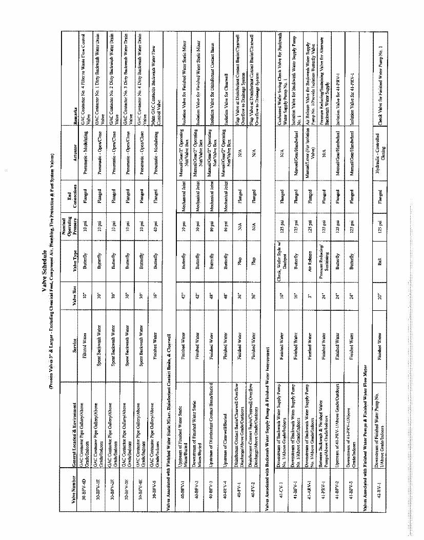
Val
Ve
Sch
edul
e(P
roce
ssV
alve
s3"
&La
rger
-E
xclu
ding
Che
mic
alFe
ed,C
ompr
esse
dA
ir,
Plu
mbi
ng,F
ireP
rote
ctio
n&
Fuel
Sys
tem
Yal
ves}
Nom
inal
Ope
ratin
gE
ndV
alve
Nm
uber
Genera
lloca
tion&
Envi
ronm
ent
Ser
vice
Val
veS
ize
Val
veT
ype
Pre
sser
eC
onne
ctio
nsA
ctua
tor
Rem
arks
30-B
FV-4
DFi
ltere
dW
ater
10"
But
terf
ly10
psi
Flan
ged
Pne
mna
tic-M
odul
atin
gG
AC
Con
tact
orN
o4
Filte
rto
Was
teFl
owC
ontro
l
30-B
FV
-lESp
entB
ackw
ash
Wat
er30
"B
utte
rfly
10ps
iFl
ange
dP
neum
atic
-O
pen/
Clo
seA
CC
onta
cter
No.
1D
itty
Ba
ckM
hW
ater
Dra
in
30-B
F¼2E
Spe
ntB
ackw
ashW
ater
30"
But
terß
y10
psi
Flan
ged
Put
umat
ic-O
pen/
Clo
se
30-B
F¼
3ES
pent
Bac
kwas
hW
ater
30"
Butterf
ly10
psi
Flan
ged
Pne
umat
ic-
Ope
n/C
lose
CC
onta
ctor
No.
3D
irty
Bac
kwas
hW
ater
Dra
in
34B
F¼
4ESp
entB
ackw
ash
Wat
er30
"B
utte
rßy
10ps
iFl
ange
dP
ncum
atic
-Ope
n!C
lose
Con
tact
orN
o.4
Dirt
yB
ackw
ash
Wat
erD
rain
34B
F¼
5Fi
nish
edW
ater
16"
But
terf
ly40
psi
Flan
ged
Puc
umat
ic-
Mod
ulat
mg
Mai
nG
AC
Con
tact
erBa
ckw
ash
Wat
erFl
ow
Vel
ves
Ass
ocia
ted
with
Fird
shed
Wat
erS
tatic
Min
er,D
iskf
ecta
ntC
onta
stB
anu,
&C
lear
wel
l
Ups
trea
mofF
inis
hed
Wat
erS
tatic
-.
-.
Man
ual/G
ear/
2"O
pera
ting
40-B
F¼
lM
ixer
/Bur
ied
reh
ed
wm
er
42"
But
terf
ly10
psi
Mec
hani
calJ
oint
Nut
/Val
veB
ox
Dow
nstre
amof
Fini
shed
Wat
erS
tatic
Man
ual/G
ear/2
"O
pera
tin40
-BF
V-2
Mkn
tBW
Fin
ishe
dWat
er42
"B
utterf
ly10
psi
Mec
hani
ca1J
oint
Nu
t/V
alv
eB
ox
4B
FW
3U
pstr
eam
ofD
isin
fect
antC
onta
ctB
asin
/Bur
ied
Fin
ishe
dW
ater
43"
Butterf
ly10
psi
Mec
hani
cal
loin
tM
anua
VG
earf
TO
psa
tmg
Isol
atio
nV
alve
for
Dis
infe
ctan
tC
onta
ctB
asin
.........
.N
ut/V
alv
eB
ox
40-B
FV
-4U
pstr
eam
ofC
lear
wel
l/Bur
ied
Fin
ishe
dW
ater
48"
Butterf
ly10
psi
Mec
hani
calJ
oint
Isol
atio
nV
alve
for
Cle
arw
ell
Nut
/Val
veB
ox
Dis
infe
cttín
tCon
tact
Bas
in/C
lear
wel
lOve
rflo
wFi
nish
edW
ater
36"
Flap
NA
Fian
ged
N/A
Flap
Val
veat
Dis
infe
clan
tCon
tact
Bas
in/C
lear
wel
lD
isch
mB
e/A
bove
Gra
de/O
utdo
ors
Ove
rflo
wto
Dra
inag
eSy
stem
F¼
lD
isin
fect
antC
onta
ctB
asin
/Cle
arw
ellO
verß
ew36
"Fl
apN
/AFl
ange
dN
/AFl
apV
alve
atD
isin
fect
antC
onta
ctB
asin
/Cle
arw
ell
Dis
char
ge/A
bove
Gra
de/O
utdo
ors
Ove
rflö
wto
Dre
9S
yste
m
Va
lve
Ass
acia
ted
with
Bac
kwas
hW
ater
Sup
ply
Pum
p&
Fin
ishe
dW
ater
Inte
conn
ect
sh
dB
ac
We
rS
upM
mnp
Fini
shed
Wat
er16
"12
5ps
iFl
ange
dN
/AN
o.1/
Abo
veG
rade
/Indo
ci·s
Das
hpot
Wat
erS
uppl
yP
ump
No.
I
41-B
FV-1
Dow
nstre
amo
fBac
kwas
hW
ater
Sup
ply
Puro
p.
.B
utte
rfly
125
psi
Flan
ged
Man
ual/G
ear/H
andw
heel
isol
atio
nV
alve
for
Back
was
hW
ater
Sup
ply
Pmnp
No.
1/A
bove
Gra
de!In
door
sN
o.1
41-A
R¼
le2
H1BS
CW
8Wnp
Fini
shed
Wat
r3
Air
R¼le
ase
125
psi
Flan
ged
Manual/Im
(For
lsol
atio
nA
irR
elea
seVa
hre
fuBa
pkw
ash
War
sS
uppl
yN
o.1/
Abo
veG
rade
/Indd
ors
..V
alve
)P
an
pN
o.1/
Pro
vide
Isol
atio
nB
utterf
lyV
ulve
41-P
RW
Bet
wee
nB
ackw
ash
&F
inis
hed
Wat
erP
ress
ure
Red
ucin
g/P
ress
ure
Red
ucin
g/S
usta
inin
gV
alve
for
Alte
rnat
eP
umps
/Abo
veG
rade
ilndo
ors
Sus
tain
ing
Bac
kwas
hW
ater
Sup
ply
4l-B
FV
-2U
pstr
eam
of41
-PR
¼1/
Aho
veG
rade
/Out
door
sF
inis
hedW
ater
24"
Butterf
ly12
5psi
Flan
ged
Man
ual/G
ear/
Han
dwhe
elIs
ola
tionV
alv
efo
r41-P
R¼
l
Dow
nstr
eam
of4
1-P
R¼
l/Ab
ove
41-B
F¼3
Fini
shed
Wat
er24
"B
utte
rfly
125p
siFl
ange
dM
anua
l/Gen
:/Han
dwhe
elIs
olat
ionV
elve
for4
1-P
R¼
1
Val
vesA
asoc
iate
dw
]thFi
nish
edW
ater
Pum
pa&
Fini
shed
Wat
erF
low
Met
er
Dow
ristre
amo
fFin
ishe
dW
ater
Pum
pN
o..
.H
ydra
ulic
-Con
trolle
d42
-B1
Funs
hed
Wat
er20
"B
all
125
psi
Flan
ged
Che
ckV
alve
fofF
inis
ed
Wat
erPu
mp
No.
I

Val
Ve
Sch
edul
e(P
roce
ssV
alve
s3"
ditLa
rger
-E
xclu
ding
Che
mira
lFee
d,C
ompr
esse
dA
ir,P
lum
bhig
,F
ireP
rote
ctio
n&
Fuel
Sys
tem
Val
ves)
Ope
ratin
gE
ndV
alve
Num
ber
Geners
lLeca
tion&
Envi
ronm
ent
Ser
vice
Val
veS
ize
Val
veT
ype
Pre
ssur
eC
onne
ctie
me
Act
uato
rR
emar
ks
Dow
nstre
amo
fFin
ishe
dW
ater
Pum
pN
o.H
ydra
ulic
-Con
trolle
d4
2-B
b2
2/A
bove
Gra
de/in
door
sFi
nish
edW
ater
20"
Bal
l12
5ps
iFl
ange
dC
heck
Val
vefo
rFi
nish
edW
ater
Pum
pN
o.2
Dow
nstr
eara
ofF
imsh
edW
sw
Pum
pN
o.H
ydra
uli
Con
trol
led
42"B
YJ
3/A
bove
Gra
deda
door
sFi
nish
edW
ater
20"
Bal
l12
5ps
iFl
ange
d.
Che
ckV
alve
forM
ised
Wat
erPu
mp
No.
3
Dow
nstr
eam
of
Fin
ishe
dW
ater
Pum
pN
o..
42-B
FV-1
Emis
hed
Wat
er20
"B
utte
rfly
125
psi
19an
ged
Man
ual/G
ear/
thm
dwhe
elIs
olat
ion
Val
vefo
rFi
nish
edW
ater
Pum
pN
o.I
Dow
nstre
amo
fFin
ishe
dW
aw
Pum
pN
o.42
-BF
V-2
Fin
ishe
dW
ater
20"
Butterf
ly12
5ps
iFl
ange
dM
anua
l/Gea
r/H
andw
heel
Isol
atio
nV
alve
for
Fin
ishe
dW
ater
Pum
pN
o.2
Dow
ntr
eam
ofF
inis
hed
Wat
erP
ump
No
42-B
FV-3
Fini
shed
Wat
er20
"B
utte
rfly
125
psi
Flan
ged
Man
ual/G
earl
Han
dwhe
elIs
olat
ion
Val
vefo
rFi
nish
edW
ater
Pum
pN
o.3
Dow
nshe
amofM
ish
ed
Wat
zrP
ump
No.
42-B
F¼
4F
inis
edW
ater
20"
But
terf
ly12
5ps
iFl
ange
dM
anua
l/Geú
/Han
dwhe
elIs
olat
ion
Val
vefo
rFi
nish
edW
ater
Pum
pN
o.4
Dow
nstr
eam
ofk
ish
ed
Wat
erP
ump
No.
42-B
FV
-55/
Abo
veG
rade
ando
ors
Fin
ishe
dW
ater
20"
Butterf
ly12
5pa
i19
ange
dM
anua
l/Gea
r/H
andw
heel
hola
tion
Val
vefu
rhis
hed
Wat
erP
ump
No.
5
Dow
nsuc
amofF
inis
hed
Wat
erP
ump
No.
42-B
FV
46/
Abo
veG
rade
/indo
ors
Fini
shed
Wat
er20
"B
utte
rfly
125
psi
Flan
ged
Man
ual/G
eer/
Han
dwhe
elIs
olat
ion
Vel
vefo
rFi
nish
edW
ater
Pum
pN
o.6
42-B
F¼
7.
Fin
ishe
dW
ater
42"
Butterf
ly12
5pa
iM
echa
nica
lJoi
ntg
Isol
atio
nV
alve
forhis
hed
Wat
erhw
Met
er
42-B
FV8
Fini
shed
Wat
erP
ump
Roo
mH
ydra
ulic
Oil
4"B
utte
rfly
10
psi
Flan
ged
Man
ual/L
ever
Isol
atio
nV
alve
for
Air/
Oil
Acc
umul
ator
Syst
em
42-B
FV
-9F
inis
hed
Wat
erP
ump
Roo
mH
ydra
ulic
Gil
4"B
utterf
ly15
0ps
iFl
ange
dM
anua
uLev
erIs
olat
ion
Val
vefo
rA
ir/O
ilA
ccum
ulat
orS
yste
m
Dow
nstre
amof
Fini
shed
Wat
erPu
rop
No.
Wel
lPum
pA
ir12
5ps
iFl
ange
d1/
Abov
eG
rade
/indo
ors
Rel
ease
Va]V
e)Pu
mp
No.
l/Pro
vde
Isol
atio
nB
utte
rfly
Val
ve
42-A
R¼
2D
owns
tream
ofFi
nish
edW
ater
Pum
pN
o.
Fini
shed
Wat
er3"
125
psi
Flan
ned
Man
ual/L
ever
(For
Isol
atio
nW
ellP
ump
Air
Rel
ease
Val
vefo
rFi
nish
edW
ater
2/A
bove
Gra
de/In
door
sR
eleM
eV
ulve
)Pu
mp
No.
2/P
rovi
deIs
olat
iou
But
terf
lyV
alve
42-A
RV
-3N
wE
ham
oS
Wah
PN
PN
aFi
nish
edW
ater
.6"
Wel
lPH
PA
ir12
5ps
iFl
ange
d3/
Abo
veG
rade
/[ndo
ors
Rel
ease
Val
ve)
Pum
pN
o.3/
Pro
vide
Isol
atio
nB
utte
rßy
Val
ve
42-G
V-1
Fini
shed
Wat
e8"
Gat
e(T
appi
ngV
alve
)12
5us
iN
EE
edW
ed
MO
pera
tsg
Tapp
ing
Val
veFo
rO
n-S
iteW
ate
Sup
ply
Syst
emW
ater
l'um
pS
tatio
n/B
urie
d-
Jom
tN
ut/V
alve
Böx
42-G
V-2
Nor
thea
sto
fGA
CC
onta
ctor
/Bur
ied
Fin
ishe
dW
ater
6"G
ate
125
psi
Mec
hani
calJ
oint
ogG
ate
Val
vefo
rFi
reH
ydra
nt..
Nur
/Val
veB
ox
4241
V-3
Wes
töfG
AC
Con
tact
or/B
urie
dFi
nish
edW
ater
6"G
ate
125
psi
Mec
hani
calJ
oint
Gat
eV
alve
forF
ireH
ydra
nt
42
-G¼
4F
inis
hed
Wat
erB"
Gat
e12
5ps
iM
echa
nica
lJoi
ntG
ate
Val
vefo
rF
ireP
roec
tion
Sys
tem
42
-G¼
5F
inis
hed
Wat
er3"
Gat
e12
5ps
iM
echa
nica
lJoi
ntBu
dng
/Bur
ied
Nut
Val
veB
oxO
pera
tions
Bui
ldin
g
42
-G¼
óN
orth
ofC
hem
ical
Sto
rage
Are
as/B
urie
dbis
hed
Wat
er6"
Gat
e25
psi
Mec
hani
calJ
oint
Gat
eV
aive
for
Fire
Hyd
rant
42-G
¼5
Fini
shed
Wat
er6"
Gat
e12
5ps
iM
echa
nica
lJoi
ntG
ate
Val
vefo
rFi
reH
ydta
at
Val
ves
Ass
eeis
ted
with
Gra
vity
Thi
cken
er

Val
Ve
Sch
edul
e(P
roce
ssV
alve
s3"
&La
rger
-E
xclu
ding
Che
atic
alFe
ed,C
ompr
esse
dA
ir,
Plu
mbi
ng,F
ireP
rote
ctio
n&
Fue
lSys
tem
Val
ves)
Nom
inal
Ope
ratin
gE
ndV
alv
eN
onth
er
Ge
ne
rallo
ca
tio
n&
En
vire
nre
en
tS
ervi
ceV
alv
eS
ize
Valv
eT
ype
Pre
sser
eC
onne
ctio
nsA
ctuato
rR
emar
ks
50-P
V-1
Wes
tSid
eo
fGra
vity
Thic
kene
r/Bur
ied
Unt
hick
ened
Sind
se12
"P
lug
10ps
iM
echa
nica
lJoi
ntannam
ar/
2"
Op
era
hIs
olat
ion
Val
vefo
rThi
cken
er-I
nflu
ent
Nut
/Val
veB
ox
50-P
V-2
Nor
thea
stSi
deof
Om
vity
Thic
kene
r/Bur
ied
Thic
kene
dSl
udge
8"P
lug
10ps
iM
echa
nica
lJoi
ntIs
olat
ion
Val
vefo
rThi
cken
er-S
indg
eN
ut/V
aive
Box
Val
ves
Ass
ocia
ted
with
Thic
kene
dS
indg
eP
amps
51-P
V-1
A1p
stre
amof
Thic
kmed
Slud
geP
ump
No'
Thic
kene
dSl
udge
8"P
lug
10pp
Flun
ged
Man
ual/G
ear/H
audw
heel
51-P
V-2
ATh
icke
nedS
tudg
e8"
Plug
:10
psi
Flen
ged
Man
ua|/G
ear/l
fand
whe
el2/
Abo
veG
rade
/indo
cra
Slud
geP
ump
No,
2-
Suc
tion
Side
51
{V-1
Nw
nM
rem
ofW
edM
uP
ep
No.
Thi
cken
edS
ludg
e6"
Che
ck20
psi
Flan
ged
N/A
Rub
berF
inpp
erS
win
gC
heck
Val
vefo
rTh
ick.
eaed
1/Ab
ove
Gra
de/le
door
sSl
udge
Pum
pN
o.1
M-C
V-2
Dow
nst
reara
ofT
hic
kenedS
ludgeP
um
pN
o.
Thi
cken
edS
ludg
e6"
Che
ck2
0p
siFl
ange
dN
/A-
2/A
bove
Gra
de/in
door
aSl
udge
Pum
pN
o.2
SI-
PV
-1B
Thi
cken
edS
ludg
e6"
Plu
g2
0p
siFl
ange
dM
anua
l/Gea
r/H
andw
heel
sW
wa
en
ed
1/Ab
ove
Gra
de/In
dour
sSl
udge
Ptu
npN
o.I
-D
isch
arge
Side
$1-P
V-2
BTh
icke
nedS
ludg
e6"
Plu
g20
psi
Flen
ged
Man
ual/G
ear/H
andw
heel
2/A
bove
Gra
de/in
door
sS
ludg
eP
ump
No.
2-
Dis
char
geS
ide
SI-P
V-3
Val
veP
itinS
ludg
ePum
pBui
ldin
g/in
door
sTh
icke
nedS
ludg
e8"
Plu
g10
pai
Flan
ged
Man
ual/G
ear/H
amlw
heel
Isol
atio
nVal
vefo
rThi
cken
edS
ludg
ePum
ps
51-P
V-4
Thic
kene
dSt
adge
6"P
lug
20ps
iM
echa
nica
lJoi
ntM
ënua
l/Gea
r!2"
Ope
ratin
gD
iver
sion
Val
ve-D
irect
sFl
owto
Slud
geD
ryin
gD
isch
arge
Man
ifohl
/Bun
edN
ut/V
élve
Box
Beds
orSp
entB
ackw
ash
Wat
erTa
nk
Sl-P
V-5
Dom
1re
no
fMck
ened
Slud
geP
mp
Thic
kene
dSl
udge
6"P
lug
20ps
iM
echa
nica
lJoi
ntM
anua
l/Gea
r/2"
Ope
ratin
gD
iver
sion
Val
ve-D
irect
sFl
owto
Slud
geD
ryin
gD
iwha
rge
Manifo
ld/B
aie
dN
ut/V
alve
Box
Bed
sor
Spe
ntB
ackw
ash
Wat
erT
ank
51-G
V-1
Thic
kene
dSl
udge
Pum
pR
ecru
Pota
ble
Wat
er6"
Gat
e15
0ps
iFl
ange
dM
anua
l/Han
dwhe
elis
olat
ion
valv
efo
rSia
mes
eco
nnec
tion
Val
vesA
ssoc
iate
dw
ithS
led
ge
Re
cycl
eP
um
ps
52-P
V-1
AU
pstr
eant
ofS
ludg
eRec
ycle
Pep
No
Slud
ge8"
Plu
g10
psi
Flan
ged
Man
ual/G
ear/H
endw
heel
isW
wfm
Slu
dh
k1/
Abo
veG
rade
/Indo
ors
Ptu
npN
o.1
-su
ctio
nS
e
52-C
V-1
wnM
mud
geR
eeP
ep
No
Slu
dge
6"C
heck
20ps
iFl
ange
dN
/A1/
Abo
veG
rade
/fudo
ors
Rec
ycle
Pm
npN
o.I
52-P
V-1
BSl
udge
6"P
lug
20ps
iFl
ange
dM
enna
l/Gea
r/Han
dwhe
el..
1/A
bove
Gra
de/In
dour
sS
hulg
eP
ump
No.
1-
Dis
char
geS
ule
52-P
V-3
Val
veP
itinS
ludg
eP·.
unpB
uGëi
ng/In
door
sS
ludg
e8"
Plu
g10
psi
Flan
ged
Man
ual/G
ear/
Han
dwhe
elre
serv
edfo
rfu
ture
pum
p)
52
-PV
4S
ludg
e6"
Plu
g20
psi
Mec
hani
calJ
oint
Men
eal/G
ear/
2"O
pera
ting
Div
ersi
onV
alve
-D
irect
sF
low
toT
hick
ener
orD
isch
arge
Man
ifold
/Bur
ied
Nut
/Val
veB
oxSl
udge
Dry
ing
Beds
52-P
V-5
n8W
m°N
ud
8e
Re
Pe
pS
ludg
e6"
Plu
g20
pai
Mec
hani
calJ
oint
Man
ual/G
ear/
2"O
pera
ting
Div
ersi
onV
alve
-D
irect
sF
low
toT
hick
ener
orD
isch
eme
Man
ifold
/Bm
ied
Nut
/Val
veB
oxSl
udge
Dry
ing
Beds
Val
ves
Ass
ocia
ted
with
Slu
dge
Dry
ing
Bed
s
60-P
WO
n6"
TSL
frora
TSI./
Rec
ycle
Ptun
pS
tatio
nTh
icke
ned
Slud
ge6"
Plu
g10
psi
Mec
hatu
calJ
oint
¯W
est
ofR
owA
/Bur
ied
Nut
/Val
veB
oxN
Bur
ied

Valv
eS
ched
ule
(Pro
cess
Val
ves
3"
&Im
rger
-E
xclu
ding
Che
mic
alFe
ed,C
empr
esse
dA
ir,P
lum
bing
,Fire
Pro
tect
ion
&F
uelS
yste
mV
alve
s)
Nom
inal
Op
erö
ing
End
Val
veN
umbe
rG
elde
ralL
ocat
ion
&E
nvi
enm
ent
Ser
vice
Val
veSi
zeV
alve
Type
Prc
asur
eC
onne
ctio
nsA
ctua
tor
Rem
arks
64
Pw
2m
frorn
TS
IR
ecyc
lePu
rnp
Stá1
ion
Thic
kene
dSl
udge
6"P
lug
10ps
iM
echa
nica
lJoi
ntM
anua
l/Gea
r/2"
Ope
ratin
gSl
udge
Dry
ing
Beds
hola
tion
Val
vefo
rRow
B&
Bet
wee
nR
owB
and
C/B
urie
dN
ut/V
alve
Box
C/B
urie
d
60-P
V-3
Thic
kene
dSl
udge
6"P
lug
10ps
iM
echa
nica
lJoi
ntM
anua
l/Gea
r/2"
Ope
ratin
gSl
udge
Dry
ing
Beds
hola
tion
Val
vefo
rR
owD
&B
etw
emR
owD
and
E/B
urie
dN
ut/V
alve
Box
E/B
mie
d
60-P
V4
Thic
kene
dSl
udge
6"P
lug
10ps
iM
echa
nica
lJoi
ntn
era
%ge
gB
e6M
ah
Me
hM
&B
etw
een
Row
Fan
dG
/Bin
ied
Nei
/Val
veB
ox
G/B
urie
d
60
-P¼
5T
hick
ened
Slu
dge
6"P
lug
10ps
iM
echa
nica
lJoi
ntM
anua
l/Gea
r/2"
Ope
ratin
gS
ludg
eD
ryin
gB
eds
Isol
atio
nV
alve
for
Row
H&
Bet
wee
nR
owH
and
I/Bun
edN
ut/V
alve
Box
I/Bur
ied
60-P
½6
Pa
Thic
kene
dSl
udge
6"P
lug
10ps
iM
echa
nica
lJoi
ntM
anua
l/Gea
r/2"
Ope
ratin
gSl
udge
Dry
ing
Beds
isol
atio
nV
alve
forR
owEa
sto
fRow
I/Bur
edN
ut/V
alve
Box
J/B
eied
60-P
¼A
-1T
hick
ened
$lud
ge4"
Plu
g10
psi
Flan
ged
Man
ual/L
ever
Gra
de/O
utde
A2/
Abo
wG
rade
/Out
door
s
6Cw
P¼A-
2Th
icke
nedS
ludg
e4"
Plu
g10
psi
Flan
ged
Man
ual/L
ever
ae
agB
edsA
3&G
rade
!Out
door
sA
4/A
bove
Gra
ddO
utdo
ors
60-P
V-A
-3Th
icke
ned
Slud
ge4"
Plu
g10
psi
Flan
ged
Man
ual/L
ever
onW
wudy
ngB
en
M&
Gra
ddO
utd
A6/
Abo
veG
rade
/Out
door
s
Sle
dge
Dry
ing
Bed
sA
7&
A8/
Abo
veIs
olat
ion
Val
vefo
rS
ludg
eD
ryin
gB
eds
A7
&G
radd
Out
door
sA
B/A
bove
Gra
ddO
utdo
ors
60-P
V-A
-5uge
DBe
ds.M
&A
Thic
kene
dSl
udge
4"P
lug
10ps
iFl
ange
dM
anua
l/Lev
erG
rade
/Out
dooM
AIO
/Abo
veG
rade
/Out
door
s
60-P
V-B
4Sl
udge
Bry
ing
Beds
BI&
B2/
Abo
veTh
icke
ned
Slud
ge4"
Plu
g10
psi
Flan
ged
Man
ual/L
ever
...........i..
B2
/A
bm
Gradd&
&ors
64P
¾B
-2Th
icke
ned
Slud
ge4"
Plu
g10
psi
Flan
ged
Man
ual/L
ever
Isol
atio
nV
alve
for
Slud
geD
ryin
gBe
dsB3
&G
rade
/Out
door
sB
4/A
bove
Gra
de/O
utdo
ors
60-P
¼B
-3Sl
udge
Dry
ing
Beds
B5
&B
6/A
bove
hola
tion
Val
vefu
rS
imig
eD
ryin
gBe
dsB5
&G
radd
Out
door
sB
6/A
bove
Gra
de/h
tdoa
ra
60··P
WB-
4Th
icke
nedS
ludg
e4
Plu
g10
psi
Flan
ged
Man
ual/L
ever
Gra
de/O
utdo
ors
..B
8/A
bove
Gra
de/O
u&or
s
60-P
V-B
-5Th
icke
ned$
ludg
e4"
Plu
g10
psi
Flan
ged
Man
ual/L
ever
on
Ww
udgeW
ngB
c6M
&de
/Out
door
sB
10/A
bove
Gra
de/O
utdo
ors
60-P
¼C
-1Sl
udge
Dry
ing
Beds
Cl&
C2/
Abo
veTh
icS
Pig
Mp
ih
We
Isol
atio
nV
elve
for
Slud
geD
ryin
gBe
dsC
l&
Gra
de/O
utdo
ors
C2/h
ve
Gra
de/O
utda
ars
60
-PV
GSl
udge
Dry
ing
Beds
C3
&C
4/A
bove
Thic
kene
dSl
udge
4"P
lug
10ps
iFl
ange
dM
anua
l/Lev
erIs
olat
ion
Val
vefo
rSl
udge
Dry
ing
Beds
C3
&G
rade
/Out
door
sC
4/A
bove
Gra
de/O
utdo
ors
60-P
¼C
-3Th
icke
nedS
ludg
e4"
Plu
g10
psi
Flan
ged
Man
urJ/
Leve
rG
rade
/Out
door
sC
6/&
veG
rade/O
utd
oe
60-P
%C
4T
hick
ened
Slu
dge
4"P
lug
10ps
iFl
ange
dM
anua
l/Lev
erG
rade
/Out
door
sC
8/A
bove
Gra
de/O
utdo
om
60-P
¼C
-5Sl
udge
Dry
ing
Beds
C9
&C
10/A
bove
Thic
kene
dSl
udge
4"P
lug
10ps
iFl
ange
dM
anua
l/Lew
rIs
olat
ion
Val
vefo
rSlu
dge
Dry
ing
Beds
C9
AG
rade
/Out
door
s'
C10
/Abo
veG
rade
/Out
docr
s
60-P
V-D
-1Th
icke
nedS
ludg
e4"
Plu
g10
psi
Flan
ged
Man
ual/L
ever
Gra
de/O
utdo
ors
D2/
Abo
veG
rade
/Out
doon
64P
¾D
-2S
ludg
eDry
ingB
edsD
3&D
4/A
bove
Thic
kene
dSlu
dge
4*P
lug
IDps
iFl
ange
dM
anua
l/Lev
erG
rad
dQ
uta
mD
4/A
bove
Gra
de/O
utdo
ors

Val
Ve
Sch
edul
e(P
roce
ssV
alve
s3"
&La
rger
-E
xclu
ding
Che
mic
alFe
ed,C
ompr
esse
dA
ir,
Pl4
tnhi
ng,F
ireP
rote
ctio
n&
Fuel
Sys
tem
Val
ves)
Non
sina
lO
pe
ratig
End
Va
lve
Né
nip
er
Gesc
ralL
oca
tion&
Envi
rem
ment
Ser
vice
Valv
eS
ize
Valv
eT
ype
Pre
ssur
eC
onne
ctin
asA
cta
tor
Rem
arks
60-P
V-D
-3Th
icke
ned
Slud
ge4"
Plu
g10
psi
Flan
ged
Man
ual/L
ever
afin
geW
ng
Bd
M&
Gud
e/0ù
tdoo
rsD
6/A
bove
Gra
de/O
utdo
ors
60-P
V-D
4Th
icke
ned
Slud
ge4"
Plu
g10
psi
Flan
ged
Man
ual/L
ever
Isol
atio
nV
alve
for
Slud
geD
ryin
gBe
dsD
7&
Gra
de/O
utdo
or5
DB
/Abo
veG
rade
!Out
door
s
60-P
¼D
-5Th
icke
nedS
ludg
e4"
Plu
g10
psi
Flen
ged
Man
usl/L
ever
Gra
de/O
utdo
orD
IO/A
bovc
Gra
de/O
utdo
ors
60
-P¾
F1
n8B
eds
El&
mb
ow
Thi
cken
edS
ludg
e4"
Plu
g10
psi
Flan
ged
Man
ual/L
ever
Isol
atio
nV
alve
for
Slu
dge
Dry
ing
Bed
sE1
&G
rade
/Out
door
sE
2/A
bove
Gra
de/O
utdo
ors
60-P
¾E
-2Th
icke
ned
Slud
ge4"
Plu
g10
psi
Flun
ged
Man
ual/L
ever
oge
gBe
E3&
Gra
de/O
utdo
ors
E4/
Abo
veG
rade
/Oat
door
s
60-P
½E
··3
Thic
kene
dSl
udge
4"P
lug
10ps
iFl
ange
dM
anna
blev
erw
fuge
MW
MB
&G
rade
/Out
door
sE
6/A
bove
Gra
de/O
utdo
ors
60-P
V-E
45
-dge
Beds
E7
&M
/he
Thic
kene
dSl
udge
4"P
lug
tops
iFl
ange
dM
anua
l/Lev
erIs
olat
ion
Val
vefo
rSl
udge
Dry
ing
Beds
E7&
Gra
de/O
utdo
orS
ES
/Abo
veG
radc
/Out
door
s
60-P
½E
-5S
udge
Dyi
ng
Beds
B&
ElW
½w
Thic
kene
dSl
udge
4"P
lug
10ps
iFl
ange
dM
anua
l/Lev
erG
rade
/Out
doon
E10
/Abo
veG
rade
/Out
door
s
60··P
V··F
··lSl
udge
Dry
ing
Beds
F1&
F2A
bove
Th
ihd
SW
4"P
M10
pi
F1h&
mIs
olat
ion
Val
vefo
rSl
udge
Dry
ing
Beds
F1&
Gra
de/O
utdo
ors
F2/A
bove
Gra
de/O
utdo
ors
60-P
V-F
-2Th
icke
ned
Slud
ge4"
Plu
g10
psi
Flan
ged
Man
ual/L
ever
Isol
aw
fuge
Wg
Beds
M&
Gra
de/O
utdo
ors
F4A
bow
Gra
de/O
utdo
ors
60
-PV
F-3
Thi
cken
edS
ludg
e4"
Plu
g10
psi
Flan
ged
Man
ual/L
ever
Gra
de/O
utdo
ors
F6/A
bove
Gra
de/O
ctdo
ors
60
-P¼
F4
Thi
cken
edS
ludg
e4"
Plu
g10
psi
Flan
ged
Man
ual/L
ever
Gra
de/O
tdoo
rsF
S/h
ve
Gra
de/O
utdo
ors
60-P
%F-
5Th
icka
ned
Slud
ge4"
Plu
g10
psi
Fian
ged
Man
ual/L
ever
onW
We
gB
eä
B&
Gra
de/Q
atdo
ora
F10/
Abo
veG
rade
,Ost
door
s
60-P
¼G
-1T
hick
ened
Slu
dge
4"P
lug
tops
iFi
nnge
dM
anus
kLev
erIs
ola
tin
Val
vefo
rS
ludg
eD
ryin
gB
eds
G1
&G
rade
/Out
doer
sG
2/A
bove
Gra
de/O
utdo
ors
PM
Slu
dge
Dry
ing
Bed
sG
3&
G4/
Aho
veT
hick
ened
Slu
dge
4"P
lug
10ps
iFi
ange
dM
anua
l/Lev
ero
seW
MB
eW
&G
rade
/Out
door
sG
4/A
bove
Gra
de,O
atdo
ors:
60-P
¼G
-3Sl
udge
Dry
ing
Beds
G5
&G
6/A
bove
Thic
kene
dSl
udge
4"P
lug
10ps
iFl
ange
dM
anua
l/Lev
erIs
olat
ion
Val
vefo
rSlu
dge
Dry
ing
Beds
G5
&G
rade
/Out
dow
sG
6/A
bove
Gra
de/O
tdoo
rs
60-P
¼G
-4Th
icke
nedS
tudg
e4"
Plu
g10
psi
Flan
ged
Man
ual/L
ever
Gra
de/O
utdo
ora
G8/
Abo
veG
rade
,Oat
door
s
60-P
V-G
-5T
hick
ened
Stu
dge
4"P
lug
10ps
iFl
ange
dM
anua
l/Lev
erG
rade
/Out
door
sG
IO/A
bove
Gra
de/Q
utdo
ors
60-P
V-H
-1Th
icke
nedS
ludg
e4"
Plu
g10
psi
Flan
ged
Man
ual/L
ever
Gra
de/O
utdo
onH
2/½
ve
Gra
de/O
utdo
o
60-P
V-H
-2T
hick
ened
Slu
dge
4"P
lug
10ps
iFl
ange
dM
anus
l/Lev
erG
rade
/Out
doór
sH
4/A
bove
Gm
de/O
utdo
o
64P
WH
-3Th
icke
nedS
tudg
e4"
Plu
g10
psi
Flan
ged
Man
ual/l
ever
Gra
de/O
utdo
ors
H6/
Abo
veG
rade
/Out
door
s
60-P
¼H
4Th
ickc
ued
Slud
ge4"
Plu
g10
psi
Flan
ged
Man
ual/L
ever
Isol
atio
nV
alve
forS
iudg
eD
ryin
gBe
dsH
7&
Gra
de/O
utdo
ors
H8/
Abo
veG
rade
/Out
door
s

Val
Ve
Sch
edul
e(P
roce
ssV
alve
s3
"&
Larg
er-
Exc
ludin
gC
hetn
ical
Fee
d,C
ompr
esse
dA
ir,
Plu
mbin
g,F
ire
Pro
tect
ina
&F
uel
Sys
tem
Val
ves)
Nom
inal
Opera
ting
End
Valv
eN
untb
er
Genera
llocation&
Environm
ent
Ser
vice
Valv
eS
ize
Valv
eT
ype
Pre
ssur
eC
onne
ctio
nsA
ctuato
rR
emar
ks
60-P
V-H
-5M
udge
gB
eds
W&
HW
hw
Thi
cken
edS
tudg
e4"
Plu
g10
psi
hg
ed
Man
ual/L
ever
Gra
de/O
utdo
ors
H10
/Abo
veG
rade
/Out
door
s
60-P
V4-
1Th
icke
nedS
ludg
e4"
Plu
g10
csi
Flan
ged
Man
ual/L
ever
Gra
de/O
utdo
ors
12/A
bove
Gra
de/O
utdo
ots
Slud
geD
ryin
gBe
ds13
&14
/Abo
veTh
icke
ned
Slud
ge4"
Plu
g10
psi
Flan
ged
Man
ual/L
ever
Gra
de/O
utdo
ors
14/A
bove
Gra
de/O
utdo
ors
60-P
V4-
3Th
icke
ned
Slud
ge4"
Plu
gto
psi
Flan
ged
Ma
nu
alh
ver
Isol
atio
nV
alve
for
Slud
geD
ryin
gBe
ds15
&G
rade
/Out
door
s16
/Abo
veG
rade
/Out
door
s
64P
V4-
4Th
icke
nedS
ludg
e4"
Plu
g10
psi
Flan
ged
Man
ual/L
ever
Gra
de/O
utdo
ors
IB/A
bove
Gra
de/O
utdo
ors
60-P
V4-
5Th
icke
ned
Slud
ge4"
Plu
g10
psi
Flan
ged
Man
ual/L
ever
Isol
atio
nV
alve
for
Slud
geD
ryin
gBe
ds19
&G
rade
/Out
door
sIl0
/Abo
veG
rade
/Out
door
s
64P
V-J
-lT
hick
ened
Slu
dge
4"
Plu
gIO
psi
Flan
ged
Man
ual/L
ever
Cua
de/O
utdo
ors
2/A
bove
Gra
de/O
utdo
ors
60-P
V··J
··2Sl
udge
Dsy
ing
Beds
D&
14/A
bove
Thic
kene
dSl
udge
4"P
lug
10ps
iFl
ange
dM
an
ua
lhve
rG
rade
/Out
door
sJ4
/Abo
veG
rade
/Out
door
s
60-P
V-J
-3Th
icke
nedS
ludg
e4"
Plu
g10
psi
Flan
ged
Man
ual/L
ever
Gra
de/O
uclo
ors
J6/A
bove
Gra
de/O
utdo
ors
60-P
V-J
·4T
hick
ened
Slu
dge
4"
Plu
g10
psi
Flan
ged
Man
ual/L
ever
Isol
atio
nV
alve
for
Slu
dge
Dry
ing
Bed
sJ7
&G
rade
Ou
tdo
ors
J8/A
bo
veG
rad
e/O
utd
oo
rs
60-P
V-J
-5T
hick
ened
Slu
dge
4"
Plu
g10
psi
Fhan
ged
Man
ual/L
ever
WW
fMM
ge
Wng
Bc6
B&
Gra
de/O
utdo
ors
J10
Abo
veG
rade
/Out
door
s
Val
ves
Ass
oels
ted
wkh
Filt
rate
Pum
pS
tatio
n
EC
V-1
Val
veV
au
ltF
iltra
teP
ump
Sta
tion
Filt
rate
8"C
heck
20ps
iFl
ange
dN
/A
61-C
V-2
Val
veV
ault
@Fi
ltrat
eP
ump
Sta
tion
Fihr
ate
8"C
heck
20ps
iFh
mge
dN
/AR
ubbe
rFl
appe
rChe
ckV
alve
for
Filtr
ate
Pum
pN
o.2
61-P
V-I
Val
veV
au
lt@
Filt
rate
Pum
pS
tatio
nF
iltra
te8"
Plu
g20
psi
Flan
ged
Man
ual/G
ear/
Han
dwhe
elIs
olat
ion
Val
vefu
Filt
nite
Pum
pN
o.!
61-P
V-2
Val
veV
anit
@Fi
ltrat
eP
ump
Sta
tion
Filtr
ate
8"P
lug
20ps
iFl
ange
dM
anua
l/Gea
r/Han
dwhe
elIs
olat
ion
Val
vefo
rFi
ltrat
ePu
np
No.
2
61-P
V-3
Valv
eV
ault@
Fih
rate
Pum
pS
tatio
nF
iltra
te8"
Plu
g2
0p
siFl
ange
dM
anua
l/Gea
r/H
andw
beel
Val
ves
Ass
ocia
ted
with
Spe
atB
ackw
ash
Wate
rS
tora
geT
ank
Nor
thS
ide
afS
pent
Bac
kwm
hW
ater
Sto
rage
Sup
erna
tant
16"
Butterf
ly10
psi
Mec
hani
calJ
oint
ng
onW
WSP
cTa
nk/B
urie
dN
ut/V
alve
Box
supe
rrna
tant
70-B
FV-2
Supe
mat
ant
16"
But
terf
ly10
psi
Mec
hani
calJ
oint
Tan
k/B
utie
dN
udV
sive
Box
Sup
ertn
atan
t
Val
ves
Ass
ocia
ted
with
Ele
vate
dB
ackw
ash
Wate
rS
tara
geT
ank
71-B
FV-1
Fini
shed
Wat
er24
"B
utte
rfly
40ps
iM
echa
nica
lJoi
tît-
Bac
kwäs
hW
ater
Sup
ply
Isol
atio
nV
alve

Valv
eS
ched
ule
(Pre
cess
Val
ves
3"
&Larg
er-
Exc
lud
ing
Che
mic
alFe
ed,
Com
pre$
aed
Air,
Flu
rab
ing
,F
ire
Pro
tect
ion
&F
uel
Sys
tem
Val
ves)
Nam
inal
Op
era
ting
En
dV
alv
eN
uéber
Genera
llocation&
Enviream
ent
Ser
vice
Valv
eS
ize
Valv
eT
ype
Pre
ssur
eC
onne
ctio
ns:
Aa
tor
Rem
arks
71-B
FV
-2F
inis
hed
Wat
er30
"B
utterf
ly40
psi
Mec
hani
calJ
oint
Bac
kwas
hW
ater
Flo
wM
eter
Isol
anon
Val
ve
71-B
FV-3
Fini
shed
Wat
er30
"B
utte
rfly
40ps
iM
echa
nica
lJoi
ntBa
ckw
ash
Wat
erFl
owM
eter
Isol
atio
nV
alve
Bac
kwes
hWat
erS
tora
geTa
nkA
bove
Fini
shed
Wat
er10
"Fl
apN
/AFl
ange
dN
/AG
rade
/Out
doon
Syst
em
Raw
Wate
rM
ain
Air
Rel
ease
Valv
a
RW
-AR
V-1
ISta
tion1
26+2
5R
awW
ater
6"A
irRel
ease
70ps
iFl
ange
dIs
olar
ian
Val
ve)
Isol
atio
nG
ate
Val
ve
RW
-AR
V-2
Sta
tion
136+
50R
awW
ater
6"A
irR
elea
se70
psi
Flan
ged
ecca
seW
wfmh
Wah
Isol
anon
Val
ve)
Isol
auon
Gat
eV
alve
RW
-AR
V-3
Stad
on39
+70
Raw
Wat
er6"
Air
Rele
ase
70ps
iFl
eage
d........
...
...
..
..
...
..
...
...
...
....
...
..................
...........................
.....
.........
.Is
ola
tio
nV
alv
e)
Iso
latio
nG
ate
Va
lve
RW
-AR
V-4
Sta
tionl
47+B
8R
awW
ater
6"A
irRel
ease
70ps
iFl
ange
dso
latio
nV
alve
)Is
olat
ion
Gat
eV
alve
RW
-AR
V-5
Sta
tion
153+
10R
awW
ater
6"A
irR
elea
se70
psi
Flan
ged
sola
tion
Va]
ve)
Isol
atio
nG
ate
Val
ve
RW
-AR
V4
Sta
tion1
78+5
0R
awW
ater
6"A
irRel
ease
70ps
iFl
ange
dso
lutio
nV
alve
)Is
olat
ion
Gat
eV
alve
RW
-AR
V-7
Sta
tion1
92+
50R
awW
ater
6"A
irRel
ease
70
psi
Flen
ged
RW
-AR
V-8
Sta
tion
216+
00R
awW
ater
6"A
irR
elea
se70
pai
Flan
ged
Isol
atio
nV
alve
)Is
oat
ion
Gat
eV
alve
RW
-AR
V-9
Sta
tion
257+
80R
awW
ater
6"A
irRe
leas
e70
psi
Flan
ged
Isol
atin
aV
alve
)ho
stio
nG
ate
Val
ve
RW
-AR
V-1
0S
tatio
n274
+00(
36.9
2Lì
Raw
Wat
er6"
AirR
elea
se70
psi
Flan
ged
Isol
atio
nV
alve
)Is
oat
ion
Gat
eV
alve
RW
-AR
V-1
1S
tatio
n274
MJ0
(44.
92L)
Raw
Wat
eró"
AirR
elea
se70
psi
Flan
ged
Isol
atio
nV
alve
)Is
oat
ion
Gat
eV
alve
RW
-AR
V-1
2S
tatio
n29
2+96
Raw
Wat
er6"
Air
Rel
ease
70ps
iFl
ange
dIs
olat
ion
Val
ve)
Iso
atio
nG
ate
Val
ve
RW
-AR
V-1
3S
tatio
n293
+01
RaW
Wat
er6"
AirR
elea
se70
psi
Flan
ged
Isol
atio
nV
alve
)h
oat
ion
Gat
eV
alve
RW
-AR
V-1
4S
tatio
p458
+00
Raw
Wat
er6"
AirR
elea
se7
0p
siFl
ange
dIs
olat
ion
Val
ve)
Iso
atto
nG
ate
Val
ve
Raw
Wat
erM
ain
Isel
aden
Val
ves
RW
-BF
V-1
Sta
tion
261+
25R
awW
ater
42"
Butterf
ly70
psi
Mec
hani
calJ
oint
Isol
atio
nV
alve
for
Raw
Wat
erM
ain
RW
-BFV
-2S
tatio
n26
1+30
Raw
Wat
er42
"B
utte
rfly
70ps
iM
echa
nica
lJoi
ntIs
olat
ion
Val
vefo
rR
awV
/ate
rMai
n
RW
-BFV
-3S
tatio
n26
1+36
Raw
Wat
er42
"B
utte
rfly
70ps
iM
echa
mca
lJoi
ntIs
olat
ion
Val
vefo
rRaw
Wat
erM
ain

Val
Ve
Sch
edul
e(P
roce
ssV
alve
s3
"&
Larg
er-
Exc
ipdin
gC
hero
ical
Feed
,C
euap
ress
edA
ir,
Plu
mb
ing
,F
ire
Pro
tect
ion
&F
uel
Sys
tem
Val
ves)
Ope
ratin
gE
ndV
alv
eN
um
be
rG
enera
llocatinn&
Environuie
nt
Ser
vice
Valv
e$iz
eV
alv
eT
ype
Pt·e
ssur
eC
onne
ctio
nsA
ctuato
rR
emar
ks
RW
-BFV
-4S
tatio
n49
9+97
Raw
Wat
er42
"B
utte
rfly
70ps
iM
echa
nica
lJoi
nt1s
olat
ion
Val
vefo
rR
awW
ater
Man
Fin
ishe
dW
ate
rl§
inIs
ola
tion
Val
ves.
FW-B
FV-1
Sta
tion
799+
7]Ei
nish
edW
ater
48"
But
terf
ly15
0ps
iM
echa
nica
lJoi
nt1s
olat
iun
Val
vefo
rFi
nish
edW
ater
Mai
n
FW
-BF
¼l
Sta
tion
800+
34Fi
äish
edW
ater
48"
But
terf
ly15
0ps
iM
echa
nica
lIoi
nt·
1sol
atio
nV
alve
for
Fini
shed
Wat
erM
ain
FW
-BF
¼3
Sta
tion
854+
75Fi
nish
edW
ater
48"
But
terD
y15
0ps
iM
echa
nica
lJoi
ntIs
olat
ion
Val
vefo
rFin
ishe
dW
ater
Mai
n
FW
-BF
V4
Stä
tion
370+
S1
Fin
ishe
dW
ater
4S"
Butterf
ly15
0ps
iM
echa
nica
l.Joi
nt1s
olut
ion
Val
vefo
rF
inis
hed
Wat
erM
ain
FW
-BF
¼5
Sta
tion
873+
91Fi
nish
edW
ater
48"
But
terf
ly15
0ps
iM
echa
nica
lJoi
ntIs
olat
ion
Val
vefo
rFin
ishe
dW
ater
Mai
n
FW
-BF
W6
Sta
tion
975+
75F
inis
hed
Wat
er4S
"B
utte
4fly
150
psi
Mec
hani
calJ
oint
1sol
utio
nV
alve
for
Fmis
hed
Wat
erM
ain
FW
-BF
¼?
Sta
tion
1032
+27
Fini
shed
Wat
er48
"B
utte
rfly
150
psi
Mec
hani
calJ
oint
Isol
atio
nV
alve
forF
inis
hed
Wat
erM
ain
FW-B
FV-8
Sta
tia10
75+2
6Fi
nish
edW
ater
48"
But
tesf
ly15
0ps
iM
echa
nica
lJoi
ntIs
olat
ion
Val
vefo
rFin
ishe
dW
ater
Mai
n
FW
-BF
V-9
Sta
tion
iI!
!+3B
Fin
ishe
dW
ater
4B"
Butterf
ly15
0ps
iM
echa
nica
lJoi
ntIs
olat
ion
Val
vefo
rF
mis
hed
Wat
erM
ain
FW
-BF
V-1
0S
tatio
n11
30+3
7F
inis
hed
Wat
er48
"B
utterf
ly15
0ps
iM
echa
nica
lJoi
ntIs
olat
ion
Val
vefo
rF
inis
hed
Wat
erM
ain
FW
-BF
¼l1
Sta
tion
i130
+89
Fin
ishe
dW
ater
48"
But
terß
y15
0ps
iM
echa
nica
lJoi
nt[s
olat
ion
Val
vefö
rF
inis
hed
Wat
erM
ain
FW
-BF
¼l2
Sta
tion
3973
+47
Fini
shed
Wat
er48
"B
utte
rfly
150
psi
Mec
hani
calJ
oint
Isol
atio
nV
alve
for
Fini
shed
Wat
erM
ain
FW
-BF
¼13
Sta
tion
3988
+00
Fin
ishe
dW
ater
4B"
Butterf
ly15
0ps
iM
echa
nica
lJom
tis
olat
ion
Val
vefo
rF
inis
hed
Wat
erM
ain
Fin
ishe
dW
ater
Mai
nA
irR
elea
seV
alve
s
FW
-AR
¼l
Sta
tion
792+
00Fi
nish
edW
ater
6"A
irR
elea
se15
0ps
iFl
ange
dIs
olat
ion
Val
ve)
Isol
etto
nG
ate
Vei
ve
FW
-AR
V-2
Sta
tion
802+
00Fm
ishe
dW
ater
t�57
5A
irR
elea
se15
0ps
iFl
ange
dIs
ola
tian
Val
ve)
Isol
atio
nG
ate
Val
ve
FW
-AR
¼S
Sta
tion
808+
90F
inis
hed
Wat
er6"
Air
Rel
ease
150
psi
Flan
ged
Isol
atio
nV
alve
)I
olat
ion
Gat
eV
alve
FW
-AR
VA
Sta
tion
840ª
05Fi
nish
edW
ater
6"A
irR
elea
se15
0pa
i11
ange
dIs
olat
ion
Val
ve)
Isol
atio
nG
ate
Val
ve
FW-A
RV
-5St
atio
n87
0+40
Finu
hed
Wat
er6"
Air
Rel
ease
150
psi
Flan
ged
soia
tion
valv
eso
anon
Gat
eva
ive
FW
-AR
V4
Sin
tion
874+
00Fi
nish
edW
ater
È'
Air
Rel
ease
150
psi
Flan
ged
Isul
atio
nV
alve
)Is
olat
imG
ate
Val
ve
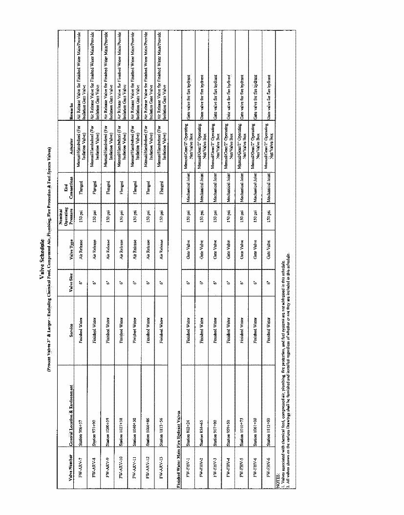
Val
Ve
Sch
edul
e(P
roce
ssV
alve
s3"
&La
rger
-E
xclu
ding
Che
mic
alFe
ed,C
ompr
esse
dA
ir,P
lum
hing
,Ne
Pro
tect
ion
&F
uelS
yste
mV
alve
s)
Opera
ting
End
Val
veN
ämbe
rG
enera
lloca
tierM
Envi
ronm
ent
Ser
vice
Val
veS
ize
Valv
eT
pe
Pre
ssur
eC
onne
ctio
nsA
ctua
tor
Ren
árks
FW-A
RW
7S
tatio
n906
+37
Fini
shed
Wat
er6"
MR
elea
se15
0psi
Flar
.ged
Man
ual/M
andw
heel
(For
AirR
elea
seV
alve
forF
inis
hedW
ater
Mai
n/P
rovi
deIs
olat
ion
Val
ve)
Isol
atio
nG
ate
Val
ve
FW-A
RV
-8S
tatio
n971
+90
Fini
shed
Wat
er6"
MR
elea
se15
0pai
Flan
ged
Man
ual/H
andw
heel
(For
AirR
elea
seV
alve
forF
inis
hedW
ater
Mai
n/P
rovi
dela
ciat
ion
Val
ve)
Isol
atio
nG
ate
Val
ve
FW
-AR
¼P
Sta
tion
1000
+59
Fini
shed
Wat
er6"
Air
Rel
ease
150
psi
Flan
ged
Man
ual/H
andw
heel
(For
Air
Rel
ëase
Val
vefo
rFi
nish
edW
ater
Mai
n/P
rovi
de..........
.......
Iso
latio
nV
elv
e)
Isola
bon
Gate
Va
lve
FW
-AR
¾l0
Sta
tion
1027
+3a
Fin
ishe
dW
ater
6"A
irR
elea
se1
Ops
iFl
ange
dM
anua
l/Han
dwhe
el(F
orA
irR
elea
seV
alve
for
Fin
ishe
dW
ater
Mai
n/P
rovi
deIs
olat
iou
Val
ve)
Isol
atio
nG
ate
Val
ve
FW-A
RV
-11
Sta
tion
1040
+50
Fini
shed
Wat
er6"
Air
Rel
ease
150
psi
Flan
ged
.(For
Air
Rel
ease
Val
vefø
rFi
nish
edW
ater
Mai
n/P
rovi
deIs
olat
ion
Val
vej
làol
atio
nG
ate
Val
ve
FW
-AR
¼l2
Sta
tion1
060+
86Fi
nish
edW
ater
6"A
irRel
eMe
150p
siFl
ange
dIs
olat
ion
Valw
)Is
olat
ion
Gat
eV
alve
FW-A
RV
-13
Sta
tion
1113
+56
Fini
shed
Wat
er6"
Air
Rel
ease
150
psi
Flan
ged
Man
ual/H
andw
heel
(Far
Air
Rel
ease
Val
vefo
rFin
ishe
dW
ater
Mai
n/P
rovi
deIs
olat
ion
Velv
e)Is
olat
ion
Gat
eVa
lve
Fin
ishe
dW
ate
rM
ain
Fire
Hyd
ran
tV
alve
s
Mal
/Gea
r/2"
On
FW
-FH
¼l
Sta
tion
B02+
24Fi
nish
edW
ater
6"G
ate
Val
ve15
0ps
iM
echa
nica
llo
int
Nut
!Val
veB
o
FW
-FH
¼2
Sw
ion
B54+
65Fi
nish
edW
ater
6"G
ate
Val
ve15
0ps
iM
echa
nica
lJoi
ntG
ate
valv
efo
rfire
hydr
ard
FW-F
HV
-3S
tatio
n90
7+00
Fini
shed
Wat
er6"
Gat
eV
alyc
I50
psi
Mec
hani
calJ
oint
Gat
eva
lve
forf
irehy
dran
t
FW-F
HV
-4S
tatio
n95
9+50
Fini
shed
Wat
er6"
Gat
eV
alve
150
psi
Mec
hani
calJ
oint
Gat
eva
lve
forf
irehy
drar
a
FW
-FH
V-5
Sta
tion
1010
+75
Fin
ishe
dW
ater
6"G
ate
Val
vël5
0pa
iM
echa
nica
lJoi
ntG
ate
valv
efo
rfir
ehy
dran
t
EW
-FH
V-6
Sta
tion
1061
+00
Fini
shed
Wat
er6"
Gat
eV
alve
150
psi
Mec
lutn
ical
Join
tG
ate
valv
efo
rfire
hydr
ant
FW-F
HV
-6S
tatio
ni1
I2M
OFi
nish
edW
ater
6"G
ate
Val
ve15
0ps
iM
echa
nica
lJoi
ntG
ate
valv
efo
rfire
hydr
ant
NO
TES:
1.V
alve
sas
soci
aud
with
chem
ical
feed
,co
mpr
esse
dëir,
plum
bing
,fir
epr
otec
tion,
and
fuct
syst
ems
are
nota
ddre
ssed
inth
issc
hedu
le.
2.A
llva
lves
show
non
the
vario
usD
raw
ings
shal
lbe
furn
ishe
dan
din
stal
led
rega
rdle
gofw
heth
eror
nott
hey
are
incl
uded
inth
issc
hedu
le

SECTION 40 42 13PROCESS PIPING INSULATION
PART 1 GENERAL
1.01 REFERENCES
A. The following is a list of standards which may be referenced in this Section:
1. American Society of Heating, Refrigerating and Air ConditioningEngineers Inc. (ASHRAE): 90.1, Energy Standard for Buildings ExceptLow-Rise Residential Buildings.
2. ASTM International (ASTM):a. B209, Standard Specification for Aluminum and Aluminum-Alloy
Sheet and Plate.b. C165 Standard Test Method for Measuring Compressive
Properties of Thermal Insulation.c. C177, Standard Test Method for Steady-State Heat Flux
Measurements and Thermal Transmission Properties by Means of theGuarded-Hot-Plate Apparatus.
d. C518, Standard Test Method for Steady-State ThermalTransmission Properties by Means of the Heat Flow MeterApparatus.
e. C534, Standard Specification for Preformed Flexible ElastomericCellular Thermal Insulation in Sheet and Tubular Form.
f. C547, Standard Specification for Mineral Fiber Pipe Insulation.g. C552, Specification for Cellular Glass Thermal Insulation.h. C585, Standard Practice for Inner and Outer Diameters of Rigid
Thermal Insulation for Nominal Sizes of Pipe and Tubing (NPSSystem).
i. C1136, Standard Specification for Flexible, Low PermeanceVapor Retarders for Thermal Insulation.
j. E84, Standard Test Method for Surface Burning Characteristics ofBuilding Materials.
k. E96, Standard Test Methods for Water Vapor Transmission ofMaterials.
3. International Code Council (ICC) International Energy ConservationCode (IECC).
4. Manufacturers Standardization Society (MSS): SP-69, Pipe Hangers andSupports.
5. Underwriters Laboratories Inc. (UL).
40 42 13 - 1Process Piping Insulation Bid SetTt#200-11740-10003 Teka Tech,Inc.

1.02 SUBMITTALS
A. Action Submittals: Manufacturer's descriptive literature.
B. Informational Submittals: Maintenance information.
PART 2 PRODUCTS
2.01 PIPE INSULATION
A. Type 1-Elastomeric:
1. Material: Flexible elastomeric pipe insulation, closed-cell structure inaccordance with ASTM C534.
2. Temperature Rating: Minus 40 degrees F to 180 degrees F.3. Nominal Density: 6 pcf.4. Conductivity in accordance with ASHRAE 90.1 and maximum numerical
value of 0.27 Btu-in/hr-square foot degrees F at 75 degrees F per ASTMC177 or ASTM C518.
5. Minimum water vapor transmission of 0.08 perm-inch per ASTM E96,Procedure A.
6. Joints: Manufacturer's adhesive.7. Flame Spread Rating: Less than 25 per ASTM E84.8. Smoke Developed Index: Less than 50 per ASTM E84.9. Manufacturers and Products:
a. Rubatex; Insul-Tube 180 or Insul-Sheet 1800.b. Armstrong; Armaflex AP.c. Approved equal.
B. Type 2-Fiberglass:
1. Material: UL rated, preformed, sectional bonded fiberglass perASTM C585 with factory applied Kraft paper with aluminum foil vaporbarrier jacket with pressure-sensitive self-sealing lap.
2. Temperature Rating: Zero to 850 degrees F.3. Conductivity in accordance with ASHRAE 90.1 and maximum
numerical value of 0.27 Btu-in/hr-square foot degrees F.4. Jacketing per ASTM C1136 with minimum water vapor transmission for
jacket of 0.02 perm-inch per ASTM E96.5. Joints: Matching pressure-sensitive butt strips for sealing
circumferential joints.6. Flame Spread Rating: Less than 25 per ASTM E84.7. Smoke Developed Index: Less than 50 per ASTM E84.
8. Manufacturers and Products:a. Owens Corning Fiberglass; ASJ/SSL-11.
40 42 13 - 2Process Piping Insulation Bid SetTt#200-11740-10003 Teka Tech,Inc.

b. John Manville; Micro-Lock 650 with AP-T Jacket.c. Approved equal.
C. Type 3-Foamglass:
1. Material: Cellular glass per ASTM C552.2. Nominal Density: 7.5 pcf.3. Compressive strength: 90 psi per ASTM C165.4. Temperature Rating: Minus 290 to 900 degrees F.5. Conductivity in accordance with ASHRAE 90.1 and maximum numerical
value of 0.29 Btu-in/hr-square foot degrees F.6. Minimum water vapor transmission for insulation of 0.00 perm-inch per
ASTM E96.7. Joints: Matching pressure-sensitive butt strips for sealing
circumferential joints.8. Flame Spread Rating: O per ASTM E84.9. Smoke Developed Index: O per ASTM E84.10. Follow manufacturer's recommendation, based upon temperature of
piping to be insulated.11. Manufacturer and Product: Pittsburgh Corning Foamglass or approved
equal.
2.02 FITTING INSULATION
A. Type 1: Same as pipe.
B. Type 2:
1. Wired in-place premolded insulation or mitered segments, or softfiberglass insulation inserts covered with premolded 20-mil minimumthickness PVC fitting covers.
2. Manufacturers:a. Manville Zeston.b. Speedline.c. Proto.d. Ceel-Co.e. Approved equal.
C. Type 3: Same as pipe.
2.03 INSULATION AT PIPE HANGERS AND SUPPORTS
A. Refer to Section 40 05 15, Piping Support Systems.
B. Copper, Ductile Iron, and Nonmetallic Pipe: High density inserts, thicknessequal to adjoining insulation, of Type 3 or other rigid insulation or
4042 13 - 3Process Piping Insulation Bid SetTt#200-11740-10003 Teka Tech,Inc.
manufactured pre-insulated pipe hangers and insulation shields per MSSSP-69, Table 5 at support locations. Extend inserts beyond shields.
C. Steel Pipe: Insulation saddles or high density inserts, thickness equal toadjoining insulation, of Type 3 or other rigid insulation or manufactured pre-insulated pipe hangers and insulation shields per MSS SP-69, Table 5 at supportlocations. Extend inserts beyond shields.
2.05 INSULATION FINISH SYSTEMS
A. Type F1-PVC:
1. Polyvinyl chloride (PVC) jacketing, white, for straight run piping andfitting locations, temperatures to 159 degrees F.
2. Manufacturers and Products:a. Johns Manville; Zeston.b. Approved equal.
B. Type F2-Paint:
1. As specified in Section 09 90 00, Painting and Coating
C. Type F3-Aluminum:
1. Aluminum Roll Jacketing: For straight run piping, wrought aluminumAlloy 3003, 5005, 1100, or 3105 to ASTM B209 with H-14 temper,minimum 0.016 inch thickness, with smooth mill finish.
2. Vapor Barrier: Provide factory applied vapor barrier, consisting of 40-pound Kraft paper with 1-mil thick low density polyethylene film, heatand pressure bonded to inner surface of aluminum jacketing.
3. Fitting Covers: Material as for aluminum roll jacketing, premolded, one ortwo piece covers, which includes elbows, tee/valves, end caps, mechanicalline couplings, and specialty fittings.
4. Manufacturers:a. RPR Products; Insul-Mate.b. Childers.c. Pabcod. Approved equal.
D. Type F4-Foamglass Jacketing:
1. Type 3 Insulation-Buried and Up to 1 Foot Above Grade: Jacket system tobe Pittsburgh Corning-Pittwrap SS, 70-mil bituminous resin with woven,glass fabric, aluminum foil layer, and plastic film coating, heat-sealed atoverlap or approved equal.
40 42 13 - 4Process Piping Insulation Bid SetTt#200-11740-10003 Teka Tech,Inc.

2. Type 3 Insulation-Greater than 1 Foot Above Grade: Jacket system to bePittsburgh Corning-Pittwrap CW30, 30-mil modified bituminousmembrane with manual jacket pressure seals or approved equal.
PART 3 EXECUTION
3.01 APPLICATION
A. General:
1. Insulate valve bodies, flanges, and pipe couplings.2. Insulate and vapor seal hangers, supports, anchors, and other piping
appurtenances that are secured directly to cold surfaces.3. Do not insulate flexible pipe couplings and expansion joints.4. Service and Insulation Thickness: Refer to Section 40 05 33 - Pipe
Heat Tracing.
3.02 INSTALLATION
A. General:
1. Install in accordance with manufacturer's instructions and as specified
herein.2. Install insulation after piping system has been pressure tested and leaks
corrected.3. Apply insulation over clean dry surfaces.4. Do not allow insulation to cover nameplates or code inspection stamps.5. Run insulation or insulation inserts continuously through pipe hangers
and supports, wall openings, ceiling openings, and pipe sleeves, unlessotherwise shown.
6. Install removable insulation sections on devices that require access formaintenance of equipment or removal, such as unions and strainer endplates.
7. Use insulating cements, lagging adhesives, and weatherproof masticsrecommended by insulation manufacturer.
8. Personnel Protection: Install on pipes from floor to 8 feet high. Install onpipes within 4 feet of platforms and to 8 feet high above platforms.
B. Connection to Existing Piping: Cut back existing insulation to remove portiondamaged by piping revisions. Install new insulation.
C. Cold Surfaces: Provide continuous vapor seal on insulation on cold surfaceswhere vapor barrier jackets are used.
40 42 13 - 5Process Piping Insulation Bid SetTt#200-11740-10003 Teka Tech,Inc.

D. Placement:
1. Slip insulation on pipe or tubing before assembly when practical to avoidlongitudinal seams.
2. Insulate valves and fittings with sleeved or cut pieces of same material.3. Seal and tape joints.
E. Insulation at Hangers and Supports: Insulation or insulation inserts to becontinuous through hanger or support.
F. Heat Traced Piping: Apply insulation after heat-tracing work is completed andinspected.
G. Roof Drains: Insulate vertical drops from roof drain to horizontal pipe, exposedand concealed horizontal piping, and 2 feet down on vertical risers fromhorizontal pipe.
H. Roof and Overflow Drain Sumps: Insulate underside.
I. Vapor Barrier:
1. Provide continuous vapor barrier at joints between rigid insulation andpipe insulation.
2. Install vapor barrier jackets with pipe hangers and supports outside jacket.3. Do not use staples and screws to secure vapor sealed system components.
J. Aluminum Jacket:
1. Use continuous friction type joint to hold jacket in place, providingpositive weatherproof seal over entire length of jacket.
2. Secure circumferential joints with preformed snap straps containingweatherproof sealant.
3. On exterior piping, apply coating over insulation and vapor barrier toprevent damage when aluminum fitting covers are installed.
4. Do not use screws or rivets to fasten the fitting covers.5. Install removable prefabricated aluminum covers on exterior flanges and
unions.6. Caulk and seal exterior joints to make watertight.
3.03 FIELD FINISHING
A. Apply coating of insulating cement where needed to obtain smooth andcontinuous appearance.
B. Where pipe labels or banding are specified for a piping system they shall beapplied to the finished insulation and not to the pipe.
40 42 13 - 6Process Piping Insulation Bid SetTt#200-11740-10003 Teka Tech,Inc.