SECTION 4 NORMAL PROCEDURES - · PDF fileModel G58 June, 2011 4-1 SECTION 4 NORMAL PROCEDURES...
58
Model G58 4-1 June, 2011 SECTION 4 NORMAL PROCEDURES TABLE OF CONTENTS SUBJECT PAGE Airspeeds For Safe Operation (5500 Lbs) . . . . . . . . . . . 4-5 Preflight Inspection . . . . . . . . . . . . . . . . . . . . . . . . . . . . 4-6 Before Engine Starting . . . . . . . . . . . . . . . . . . . . . . . . . 4-12 Engine Starting (Battery). . . . . . . . . . . . . . . . . . . . . . . . . 4-13 Cold Starts . . . . . . . . . . . . . . . . . . . . . . . . . . . . . . . . . . . 4-13 Flooded Engine . . . . . . . . . . . . . . . . . . . . . . . . . . . . . . . 4-14 Hot Starts . . . . . . . . . . . . . . . . . . . . . . . . . . . . . . . . . . . . 4-14 Before Taxi . . . . . . . . . . . . . . . . . . . . . . . . . . . . . . . . . . . 4-15 Before Takeoff (Runup) . . . . . . . . . . . . . . . . . . . . . . . . 4-18 Before Takeoff (Final Items) . . . . . . . . . . . . . . . . . . . . . . 4-20 Takeoff . . . . . . . . . . . . . . . . . . . . . . . . . . . . . . . . . . . . . . 4-20 Climb . . . . . . . . . . . . . . . . . . . . . . . . . . . . . . . . . . . . . . . 4-20 Cruise . . . . . . . . . . . . . . . . . . . . . . . . . . . . . . . . . . . . . . . . 4-22 Descent . . . . . . . . . . . . . . . . . . . . . . . . . . . . . . . . . . . . . 4-22 Before Landing . . . . . . . . . . . . . . . . . . . . . . . . . . . . . . . 4-23 Normal Landing . . . . . . . . . . . . . . . . . . . . . . . . . . . . . . . . 4-23 Balked Landing . . . . . . . . . . . . . . . . . . . . . . . . . . . . . . . 4-23 After Landing . . . . . . . . . . . . . . . . . . . . . . . . . . . . . . . . . 4-24 Shutdown and Securing . . . . . . . . . . . . . . . . . . . . . . . . 4-24 Other Normal Procedures . . . . . . . . . . . . . . . . . . . . . . . . 4-25 External Power . . . . . . . . . . . . . . . . . . . . . . . . . . . . . . . 4-25 Engine Starting using External Power . . . . . . . . . . . . 4-25
Transcript of SECTION 4 NORMAL PROCEDURES - · PDF fileModel G58 June, 2011 4-1 SECTION 4 NORMAL PROCEDURES...
Model G58
4-1
June, 2011
SECTION 4NORMAL PROCEDURES
TABLE OF CONTENTS
SUBJECT PAGE
Airspeeds For Safe Operation (5500 Lbs) . . . . . . . . . . . 4-5
Preflight Inspection . . . . . . . . . . . . . . . . . . . . . . . . . . . . 4-6
Before Engine Starting . . . . . . . . . . . . . . . . . . . . . . . . . 4-12
Engine Starting (Battery). . . . . . . . . . . . . . . . . . . . . . . . . 4-13Cold Starts . . . . . . . . . . . . . . . . . . . . . . . . . . . . . . . . . . . 4-13Flooded Engine . . . . . . . . . . . . . . . . . . . . . . . . . . . . . . . 4-14Hot Starts . . . . . . . . . . . . . . . . . . . . . . . . . . . . . . . . . . . . 4-14
Before Taxi . . . . . . . . . . . . . . . . . . . . . . . . . . . . . . . . . . . 4-15
Before Takeoff (Runup) . . . . . . . . . . . . . . . . . . . . . . . . 4-18
Before Takeoff (Final Items) . . . . . . . . . . . . . . . . . . . . . . 4-20
Takeoff . . . . . . . . . . . . . . . . . . . . . . . . . . . . . . . . . . . . . . 4-20
Climb . . . . . . . . . . . . . . . . . . . . . . . . . . . . . . . . . . . . . . . 4-20
Cruise . . . . . . . . . . . . . . . . . . . . . . . . . . . . . . . . . . . . . . . . 4-22
Descent . . . . . . . . . . . . . . . . . . . . . . . . . . . . . . . . . . . . . 4-22
Before Landing . . . . . . . . . . . . . . . . . . . . . . . . . . . . . . . 4-23
Normal Landing . . . . . . . . . . . . . . . . . . . . . . . . . . . . . . . . 4-23
Balked Landing . . . . . . . . . . . . . . . . . . . . . . . . . . . . . . . 4-23
After Landing . . . . . . . . . . . . . . . . . . . . . . . . . . . . . . . . . 4-24
Shutdown and Securing . . . . . . . . . . . . . . . . . . . . . . . . 4-24
Other Normal Procedures . . . . . . . . . . . . . . . . . . . . . . . . 4-25External Power. . . . . . . . . . . . . . . . . . . . . . . . . . . . . . . 4-25
Engine Starting using External Power . . . . . . . . . . . . 4-25
58-590000-67A8_sec04toc.fm Page 1 Thursday, May 12, 2011 9:51 AM

Model G58
4-2
June, 2011
SECTION 4NORMAL PROCEDURES
TABLE OF CONTENTS (CONT’D)
SUBJECT PAGE
Standby Attitude Indicator . . . . . . . . . . . . . . . . . . . . . . . 4-26After Starting . . . . . . . . . . . . . . . . . . . . . . . . . . . . . . . 4-26Before Takeoff . . . . . . . . . . . . . . . . . . . . . . . . . . . . . . 4-26Shutdown. . . . . . . . . . . . . . . . . . . . . . . . . . . . . . . . . . 4-27
Leaning Using the Exhaust Gas Temperature (EGT) Indication . . . . . . . . . . . . . . . . . . 4-29
Monitoring Engine Systems (Oil, Fuel, Electrical) . . . . . 4-30Monitoring the CHTs and EGTs . . . . . . . . . . . . . . . . . . 4-31Avionics. . . . . . . . . . . . . . . . . . . . . . . . . . . . . . . . . . . . . 4-31
Autopilot/Flight Director . . . . . . . . . . . . . . . . . . . . . . . 4-31General . . . . . . . . . . . . . . . . . . . . . . . . . . . . . . . . . 4-31Autopilot/Flight Director Procedures . . . . . . . . . . . 4-32Approach Procedures . . . . . . . . . . . . . . . . . . . . . . 4-41
Traffic Information Service (TIS) . . . . . . . . . . . . . . . . 4-45L-3 Communications SKYWATCH SKY497
Traffic Advisory System (if installed). . . . . . . . . . . . .4.45Cold Weather Operation . . . . . . . . . . . . . . . . . . . . . . . . 4-46
Preflight Inspection . . . . . . . . . . . . . . . . . . . . . . . . . . 4-46After Starting . . . . . . . . . . . . . . . . . . . . . . . . . . . . . . . 4-47Taxiing . . . . . . . . . . . . . . . . . . . . . . . . . . . . . . . . . . . . 4-47Before Takeoff . . . . . . . . . . . . . . . . . . . . . . . . . . . . . . 4-48Takeoff. . . . . . . . . . . . . . . . . . . . . . . . . . . . . . . . . . . . 4-48Descent . . . . . . . . . . . . . . . . . . . . . . . . . . . . . . . . . . . 4-48Landing . . . . . . . . . . . . . . . . . . . . . . . . . . . . . . . . . . . 4-48
Heater Operation. . . . . . . . . . . . . . . . . . . . . . . . . . . . . . 4-49Windshield Defogging . . . . . . . . . . . . . . . . . . . . . . . . . . 4-50
58-590000-67A8_sec04toc.fm Page 2 Thursday, May 12, 2011 9:51 AM
Model G58
4-3
June, 2011
SECTION 4NORMAL PROCEDURES
TABLE OF CONTENTS (CONT’D)
SUBJECT PAGE
Ice Protection Systems. . . . . . . . . . . . . . . . . . . . . . . . . . 4-50Before Takeoff . . . . . . . . . . . . . . . . . . . . . . . . . . . . . . 4-51
Cabin Heater . . . . . . . . . . . . . . . . . . . . . . . . . . . . . . 4-51Surface Deice System . . . . . . . . . . . . . . . . . . . . . . 4-51Electrothermal Propeller Deice . . . . . . . . . . . . . . . . 4-51Fuel Vent Heat, Stall Warning Heat, Pitot Heat,
Windshield Heat, and Ice Light . . . . . . . . . . . . . . 4-52In Flight . . . . . . . . . . . . . . . . . . . . . . . . . . . . . . . . . . . . 4-52
Surface Deice System . . . . . . . . . . . . . . . . . . . . . . 4-53Electrothermal Propeller Deice . . . . . . . . . . . . . . . . 4-53Electrothermal Heated Windshield Segment . . . . . 4-54Pitot Heat, Stall Warning Heat,
and Fuel Vent Heat . . . . . . . . . . . . . . . . . . . . . . . 4-54After Landing . . . . . . . . . . . . . . . . . . . . . . . . . . . . . . . 4-54
Simulating One-Engine Inoperative (Zero Thrust) . . . . . 4-54Practice Demonstration of VMCA . . . . . . . . . . . . . . . . . . 4-55Engine Break-In Information. . . . . . . . . . . . . . . . . . . . . . 4-56Noise Characteristics . . . . . . . . . . . . . . . . . . . . . . . . . 4-56
58-590000-67A8_sec04toc.fm Page 3 Thursday, May 12, 2011 9:51 AM

Model G58
4-4
June, 2011
Section 4Normal Procedures
THIS PAGE INTENTIONALLY LEFT BLANK
58-590000-67A8_sec04toc.fm Page 4 Thursday, May 12, 2011 9:51 AM
Normal ProceduresSection 4
Model G58
4-5
Document Date
4-5
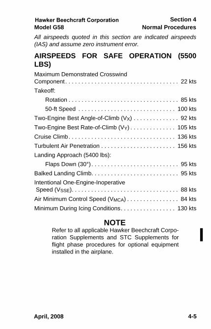
All airspeeds quoted in this section are indicated airspeeds(IAS) and assume zero instrument error.
AIRSPEEDS FOR SAFE OPERATION (5500LBS) Maximum Demonstrated CrosswindComponent . . . . . . . . . . . . . . . . . . . . . . . . . . . . . . . . . . . 22 ktsTakeoff:
Rotation . . . . . . . . . . . . . . . . . . . . . . . . . . . . . . . . . . 85 kts50-ft Speed . . . . . . . . . . . . . . . . . . . . . . . . . . . . . . 100 kts
Two-Engine Best Angle-of-Climb (VX) . . . . . . . . . . . . . . 92 ktsTwo-Engine Best Rate-of-Climb (VY) . . . . . . . . . . . . . . 105 ktsCruise Climb. . . . . . . . . . . . . . . . . . . . . . . . . . . . . . . . . 136 ktsTurbulent Air Penetration . . . . . . . . . . . . . . . . . . . . . . . 156 ktsLanding Approach (5400 lbs):
Flaps Down (30°) . . . . . . . . . . . . . . . . . . . . . . . . . . . 95 ktsBalked Landing Climb. . . . . . . . . . . . . . . . . . . . . . . . . . . 95 ktsIntentional One-Engine-Inoperative Speed (VSSE). . . . . . . . . . . . . . . . . . . . . . . . . . . . . . . . . 88 ktsAir Minimum Control Speed (VMCA) . . . . . . . . . . . . . . . . 84 ktsMinimum During Icing Conditions. . . . . . . . . . . . . . . . . 130 kts
NOTERefer to all applicable Hawker Beechcraft Corpo-ration Supplements and STC Supplements forflight phase procedures for optional equipmentinstalled in the airplane.
April, 2008
sec04.fm Page 5 Thursday, May 1, 2008 2:19 PM

Normal Procedures Model G58Section 4
4 - 6
Document Date
4-6
PREFLIGHT INSPECTION
1. CABINa. Emergency Exits. . . . . . . . . . . . . . . . . . . . . . .CHECK
1) Safety Wire (Beneath Cover). . . . . . . . . . INTACT2) Windows . . . . . . . . . . . . . . . CLOSED & LOCKED
b. Seats and Seat Belts . . . . . PROPERLY INSTALLEDc. Baggage . . . . . . . . . . . . . . . . . . . . . . . . . . . SECURE
TH04C 054024AA.AI
April, 2008
sec04.fm Page 6 Thursday, May 1, 2008 2:19 PM

Normal ProceduresSection 4
Model G58
4-7
Document Date
4-7
2. COCKPITa. Landing Gear Emergency Handcrank . . . . STOWED
AND ACCESSIBLEb. Fire Extinguisher . . . . . . . . . . . . . . . . . . . . . . CHECKc. Parking Brake . . . . . . . . . . . . . . . . . . . . . . . . . . .SETd. Control Locks . . . . . . . . . . . . . . . . . . . . . . . REMOVEe. All Switches . . . . . . . . . . . . . . . . . . . . . . . . . . . . .OFFf. Landing Gear Handle. . . . . . . . . . . . . . . . . . . .DOWN
g. Trim Tabs. . . . . . . . . . . . . . . . . . . . . . SET TO ZEROh. Battery System. . . . . . . . . . . . . . . . . . . . . . . . CHECK
1) L BAT and R BAT . . . . . . . . . . . . . . . . . . . . . . .ON2) PFD . . . . . . . . . VERIFY REVERSIONARY MODE3) Soft Keys. . . . . . . . SELECT ENGINE & SYSTEM4) L Bus & R Bus Voltages . . . . . . . . . . . . . . CHECK
a) L Bus = 23 Volts minimumb) R Bus = 23 Volts minimum
i. Landing Gear Position Lights . . . . .CHECK 3 GREENj. Annunciator Test Button . . . . . . . . . . . . . . . . PRESS
• Gear In-Transit Light andFlap Lights. . . . . . . . . . . . . . . . . . . . . ILLUMINATED
k. Exterior/Interior Lights . . . . .CHECK, AS REQUIREDl. Standby Attitude Indicator . . . . . . . . . FLAG PULLED
m. L BAT & R BAT . . . . . . . . . . . . . . . . . . . . . . . . . .OFFn. Standby Attitude Indicator . . . . . . . . . .YELLOW LED
BLINKING• Will automatically shutdown after 1 minute
3. RIGHT FUSELAGE • Static Port . . . . . . . . . . . . . . . . . . . . . . . . . . . . . . CLEAR
April, 2008
sec04.fm Page 7 Thursday, May 1, 2008 2:19 PM

Normal Procedures Model G58Section 4
4 - 8
Document Date
4-8
4. EMPENNAGE a. Vertical & Horizontal Stabilizers . . . . . . . . . . .CHECKb. Deice Boots . . . . . . . . . . . . . . . . . . . . . . . . . .CHECKc. Rudder & Elevator . . . . . . . . . . CHECK MOVEMENT
& SECURITYd. Rudder & Elevator Trim Tab. . . .CHECK SECURITY,
ALIGNMENT WITH ELEVATOR & RUDDERe. Static Wicks . . . . . . . . . . . . . . . . . . . . . . . . . .CHECKf. Nav Light and Rotating Beacon . . . . . . . . . . .CHECK
g. Tie Down . . . . . . . . . . . . . . . . . . . . . . . . . . REMOVE5. LEFT FUSELAGE
a. Cabin Air Intake . . . . . . . . . . . . . . . . . . . . . . . CLEARb. Cabin Air Exhaust. . . . . . . . . . . . . . . . . . . . . . CLEARc. Static Port . . . . . . . . . . . . . . . . . . . . . . . . . . . . CLEARd. All Antennas . . . . . . . . . . . . . . . . . . . . . . . . . .CHECKe. Lower Flashing Beacon . . . . . . . . . . . . . . . . .CHECK
6. LEFT WING TRAILING EDGE a. Fuel Sump Aft of Wheel Well . . . . . DRAIN & CHECK
FUELb. Fuel Vents . . . . . . . . . . . . . . . . . . . . . . . . . . . CLEARc. Flap. . . . . . . . . . . . . . . . . . . . . . . . . . . . . . . . .CHECKd. Aileron Trim Tab . . . . . . . . . . . . .CHECK SECURITY,
ALIGNMENT WITH AILERONe. Aileron . . . . . . . . . . . . . . . . . . . CHECK MOVEMENT
& SECURITYf. Static Wicks . . . . . . . . . . . . . . . . . . . . . . . . . .CHECK
g. Wing Tip . . . . . . . . . . . . . . . . . . . . . . . . . . . . .CHECK7. LEFT WING LEADING EDGE
a. Navigation and Strobe Lights . . . . . . . . . . . . .CHECK
April, 2008
sec04.fm Page 8 Thursday, May 1, 2008 2:19 PM

Normal ProceduresSection 4
Model G58
4-9
4-9
b. Fuel . . . . . . . .CHECK QTY, O RING, CAP SECURE(Always check wing tip tank (if installed) first; do notremove inboard cap if fuel is visible in tip tank.)
c. Wing Tip Tank Sump (if installed) . . . . . . . . . .DRAIN & CHECK FUEL
d. Siphon Break Port . . . . . . . . . . . . . . . . . . . . . CLEARe. Deice Boots . . . . . . . . . . . . . . . . . . . . . . . . . . CHECKf. Stall Warning Vane . . . . . . . . . CHECK MOVEMENT
g. Tie Down . . . . . . . . . . . . . . . . . . . . . . . . . . REMOVEh. ADC OAT Probe . . . . . . . . . . . . . . . . . . . . . . CHECKi. Fuel Sight Gage . . . . . . . . . . . . . . . . . . . . . . . CHECKj. Engine Oil . . . . . . . . . . . . . . . . . . 10 QTS MINIMUM
k. Engine Cowling . . . . . . . . . . . . . . . . . . . . . .SECUREl. Landing Light . . . . . . . . . . . . . . . . . . . . . . . . . CHECK
m. Engine Air Intake . . . . . . . . . . . . . . . . . . . . . . CLEARn. Propeller / Spinner . . . . . . . . . . . . . . . . . . . . . CHECK
(Nicks, Leaks, Deice Boots)o. Cowl Flap . . . . . . . . . . . . . . . . . . . . . . . . . . . . CHECKp. Left Main Gear . . . . . . . . . . . . . . . . . . . . . . . . CHECK
1) Gear Doors . . . . . . . . . . . . . . .SECURE & FLUSH2) Landing Gear Uplock Roller . . . . . . . . . . . CHECK3) W.O.W. Switch Linkage . . . . . . . . . . . . .SECURE4) Scissor Linkage. . . . . . . . . . . . . . . . . . . .SECURE5) Shock Strut . . . . . . . . . . . . .PROPER INFLATION6) Tire . . . . . . . . . . . . . . . . . . . . . . . . . . CONDITION7) Chocks . . . . . . . . . . . . . . . . . . . . . . . . . REMOVE
q. Fuel Strainer and Selector Drains . . . . . . . . . .DRAIN & CHECK FUEL
r. Fuel Sump Drain . . . . . . . . . DRAIN & CHECK FUEL
April, 2008
sec04.fm Page 9 Monday, January 12, 2009 9:07 AM
Normal Procedures Model G58Section 4
4 - 10
4-10
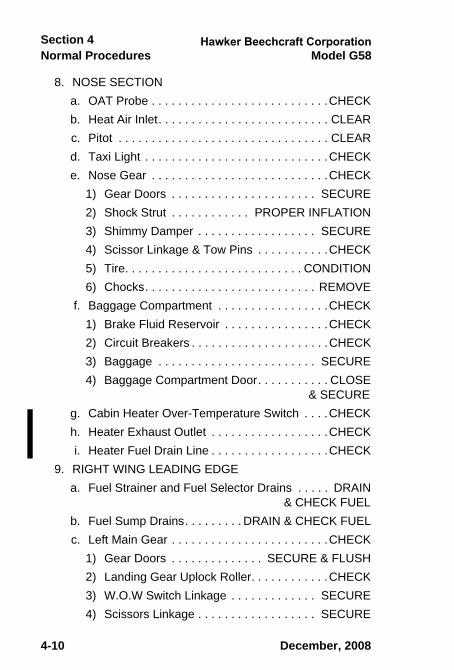
8. NOSE SECTION a. OAT Probe . . . . . . . . . . . . . . . . . . . . . . . . . . .CHECKb. Heat Air Inlet. . . . . . . . . . . . . . . . . . . . . . . . . . CLEARc. Pitot . . . . . . . . . . . . . . . . . . . . . . . . . . . . . . . . CLEARd. Taxi Light . . . . . . . . . . . . . . . . . . . . . . . . . . . .CHECKe. Nose Gear . . . . . . . . . . . . . . . . . . . . . . . . . . .CHECK
1) Gear Doors . . . . . . . . . . . . . . . . . . . . . . SECURE2) Shock Strut . . . . . . . . . . . . PROPER INFLATION3) Shimmy Damper . . . . . . . . . . . . . . . . . . SECURE4) Scissor Linkage & Tow Pins . . . . . . . . . . .CHECK5) Tire. . . . . . . . . . . . . . . . . . . . . . . . . . . CONDITION6) Chocks. . . . . . . . . . . . . . . . . . . . . . . . . . REMOVE
f. Baggage Compartment . . . . . . . . . . . . . . . . .CHECK1) Brake Fluid Reservoir . . . . . . . . . . . . . . . .CHECK2) Circuit Breakers . . . . . . . . . . . . . . . . . . . . .CHECK3) Baggage . . . . . . . . . . . . . . . . . . . . . . . . SECURE4) Baggage Compartment Door. . . . . . . . . . . CLOSE
& SECUREg. Cabin Heater Over-Temperature Switch . . . .CHECKh. Heater Exhaust Outlet . . . . . . . . . . . . . . . . . .CHECKi. Heater Fuel Drain Line . . . . . . . . . . . . . . . . . .CHECK
9. RIGHT WING LEADING EDGE a. Fuel Strainer and Fuel Selector Drains . . . . . DRAIN
& CHECK FUELb. Fuel Sump Drains. . . . . . . . . DRAIN & CHECK FUELc. Left Main Gear . . . . . . . . . . . . . . . . . . . . . . . .CHECK
1) Gear Doors . . . . . . . . . . . . . . SECURE & FLUSH2) Landing Gear Uplock Roller. . . . . . . . . . . .CHECK3) W.O.W Switch Linkage . . . . . . . . . . . . . SECURE4) Scissors Linkage . . . . . . . . . . . . . . . . . . SECURE
December, 2008
sec04.fm Page 10 Wednesday, November 12, 2008 3:27 PM

Normal ProceduresSection 4
Model G58
4-11
4-11
5) Shock Strut . . . . . . . . . . . . .PROPER INFLATION6) Tire . . . . . . . . . . . . . . . . . . . . . . . . . . CONDITION7) Chocks . . . . . . . . . . . . . . . . . . . . . . . . . REMOVE
d. Cowl Flap . . . . . . . . . . . . . . . . . . . . . . . . . . . . CHECKe. Engine Oil . . . . . . . . . . . . . . . . . . 10 QTS MINIMUMf. Engine Cowling and Doors . . . . . . . . . . . . .SECURE
g. Landing Light . . . . . . . . . . . . . . . . . . . . . . . . . CHECKh. Engine Air Intake . . . . . . . . . . . . . . . . . . . . . . CLEARi. Propeller / Spinner . . . . . . . . . . . . . . . . . . . . . CHECK
(Nicks, Leaks, Deice Boots)j. Fuel Sight Gage . . . . . . . . . . . . . . . . . . . . . . . CHECK
k. Deice Boots . . . . . . . . . . . . . . . . . . . . . . . . . . CHECKl. Tie Down . . . . . . . . . . . . . . . . . . . . . . . . . . REMOVE
m. Fuel . . . . . . . .CHECK QTY, O RING, CAP SECURE(Always check wing tip tank (if installed) first; do notremove inboard cap if fuel is visible in tip tank.)
n. Wing Tip Tank Sump (if installed) . . . . . . . . . .DRAIN & CHECK FUEL
o. Siphon Break Port . . . . . . . . . . . . . . . . . . . . . CLEARp. Navigation and Strobe Lights . . . . . . . . . . . . . CHECK
10. RIGHT WING TRAILING EDGEa. Wing Tip. . . . . . . . . . . . . . . . . . . . . . . . . . . . . CHECKb. Static Wicks . . . . . . . . . . . . . . . . . . . . . . . . . . CHECKc. Aileron . . . . . . . .CHECK MOVEMENT & SECURITYd. Flaps . . . . . . . . . . . . . . . . . . . . . . . . . . . . . . . CHECKe. Fuel Vents . . . . . . . . . . . . . . . . . . . . . . . . . . . CLEARf. Fuel Sump Aft of Wheel Well . . . . . . . . . . . . . .DRAIN
& CHECK FUELg. Utility Doors . . . . . . . . . . . . .CLOSED AND LOCKED
December, 2008
sec04.fm Page 11 Wednesday, November 12, 2008 3:27 PM
Normal Procedures Model G58Section 4
4 - 12
4-12
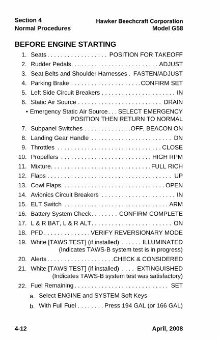
BEFORE ENGINE STARTING 1. Seats . . . . . . . . . . . . . . . . . . POSITION FOR TAKEOFF2. Rudder Pedals. . . . . . . . . . . . . . . . . . . . . . . . . . ADJUST3. Seat Belts and Shoulder Harnesses . FASTEN/ADJUST4. Parking Brake . . . . . . . . . . . . . . . . . . . . .CONFIRM SET5. Left Side Circuit Breakers . . . . . . . . . . . . . . . . . . . . . . IN6. Static Air Source . . . . . . . . . . . . . . . . . . . . . . . . . DRAIN
• Emergency Static Air Source. . . SELECT EMERGENCY POSITION THEN RETURN TO NORMAL
7. Subpanel Switches . . . . . . . . . . . . . .OFF, BEACON ON8. Landing Gear Handle . . . . . . . . . . . . . . . . . . . . . . . . DN9. Throttles . . . . . . . . . . . . . . . . . . . . . . . . . . . . . . . CLOSE
10. Propellers . . . . . . . . . . . . . . . . . . . . . . . . . . . HIGH RPM11. Mixture. . . . . . . . . . . . . . . . . . . . . . . . . . . . . .FULL RICH12. Flaps . . . . . . . . . . . . . . . . . . . . . . . . . . . . . . . . . . . . . UP13. Cowl Flaps. . . . . . . . . . . . . . . . . . . . . . . . . . . . . . . OPEN14. Avionics Circuit Breakers . . . . . . . . . . . . . . . . . . . . . . IN15. ELT Switch . . . . . . . . . . . . . . . . . . . . . . . . . . . . . . . ARM16. Battery System Check. . . . . . . . CONFIRM COMPLETE17. L & R BAT, L & R ALT. . . . . . . . . . . . . . . . . . . . . . . . ON 18. PFD . . . . . . . . . . . . . . VERIFY REVERSIONARY MODE19. White [TAWS TEST] (if installed) . . . . . . ILLUMINATED
(Indicates TAWS-B system test is in progress)20. Alerts . . . . . . . . . . . . . . . . . . . .CHECK & CONSIDERED21. White [TAWS TEST] (if installed) . . . . EXTINGUISHED
(Indicates TAWS-B system test was satisfactory)22. Fuel Remaining . . . . . . . . . . . . . . . . . . . . . . . . . . . . SET
a. Select ENGINE and SYSTEM Soft Keys
b. With Full Fuel . . . . . . . . Press 194 GAL (or 166 GAL)
April, 2008
sec04.fm Page 12 Monday, January 12, 2009 9:09 AM
Normal ProceduresSection 4
Model G58
4-13
Document Date
4-13
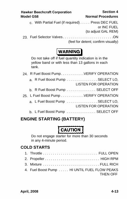
c. With Partial Fuel (if required) . . . . . Press DEC FUEL or INC FUEL (to adjust GAL REM)
23. Fuel Selector Valves. . . . . . . . . . . . . . . . . . . . . . . . . .ON (feel for detent; confirm visually)
Do not take off if fuel quantity indication is in theyellow band or with less than 13 gallons in eachtank.
24. R Fuel Boost Pump. . . . . . . . . . . .VERIFY OPERATION
a. R Fuel Boost Pump . . . . . . . . . . . . . . . . SELECT LO, LISTEN FOR OPERATION
b. R Fuel Boost Pump . . . . . . . . . . . . . . . SELECT OFF
25. L Fuel Boost Pump . . . . . . . . . . . .VERIFY OPERATION
a. L Fuel Boost Pump . . . . . . . . . . . . . . . . SELECT LO, LISTEN FOR OPERATION
b. L Fuel Boost Pump . . . . . . . . . . . . . . . SELECT OFF
ENGINE STARTING (BATTERY)
Do not engage starter for more than 30 secondsin any 4-minute period.
COLD STARTS1. Throttle . . . . . . . . . . . . . . . . . . . . . . . . . . . . FULL OPEN2. Propeller . . . . . . . . . . . . . . . . . . . . . . . . . . . . HIGH RPM3. Mixture . . . . . . . . . . . . . . . . . . . . . . . . . . . . . FULL RICH4. Fuel Boost Pump . . . . . HI UNTIL FUEL FLOW PEAKS
THEN OFF
April, 2008
sec04.fm Page 13 Thursday, May 1, 2008 2:19 PM

Normal Procedures Model G58Section 4
4 - 14
Document Date
4-14
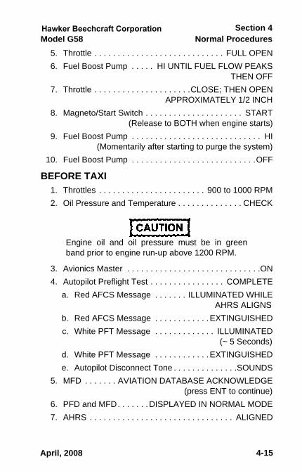
5. Throttle . . . . . . . . . . . . . . . . . . . . CLOSE, THEN OPEN APPROXIMATELY 1/2 INCH
6. Magnetos/Start Switch . . . . . . . . . . . . . . . . . . . . START (Release to BOTH when engine starts)
• The [START ENGD] Caution Alert will illuminate duringthe Start and should extinguish when starter is released.
7. Throttle (after start) . . . . . . . . . . . . . . . 900 to 1000 RPM8. Oil Pressure. . . . . . . . . . . . . . . . . . . . . . . . . . . . .CHECK
Engine oil pressure must be out of the red bandwithin 30 seconds.
9. Other Engine . . . . . . . . . . . . . . . . . . . . . . . . . . . . START REPEAT STEPS 1 - 8
FLOODED ENGINE1. Mixture. . . . . . . . . . . . . . . . . . . . . . . . . . . . . . . CUT OFF2. Propeller . . . . . . . . . . . . . . . . . . . . . . . . . . . . HIGH RPM3. Throttle . . . . . . . . . . . . . . . . . . . . . . . . . . . . . . . . . OPEN4. Magneto / Start Switch . . . . . . . . . . . . . . . . . . . . START
(Release to BOTH when engine starts)5. As Engine Starts:
a. Throttle . . . . . . . . . . . . . . . . . . . . . . . . . . . . . . . . IDLEb. Mixture . . . . . . . . . . . . . . . . . . . . . . . . . . .FULL RICH
HOT STARTS1. Mixture. . . . . . . . . . . . . . . . . . . . . . . . . . . . . . . CUT OFF2. Propeller . . . . . . . . . . . . . . . . . . . . . . . . . . . . HIGH RPM3. Fuel Boost Pump. . . . . . . . . . HI FOR 30-60 SECONDS,
THEN OFF4. Mixture. . . . . . . . . . . . . . . . . . . . . . . . . . . . . .FULL RICH
April, 2008
sec04.fm Page 14 Thursday, May 1, 2008 2:19 PM
Normal ProceduresSection 4
Model G58
4-15
Document Date
4-15
5. Throttle . . . . . . . . . . . . . . . . . . . . . . . . . . . . FULL OPEN6. Fuel Boost Pump . . . . . HI UNTIL FUEL FLOW PEAKS
THEN OFF7. Throttle . . . . . . . . . . . . . . . . . . . . .CLOSE; THEN OPEN
APPROXIMATELY 1/2 INCH8. Magneto/Start Switch . . . . . . . . . . . . . . . . . . . . . START
(Release to BOTH when engine starts)9. Fuel Boost Pump . . . . . . . . . . . . . . . . . . . . . . . . . . . . HI
(Momentarily after starting to purge the system)10. Fuel Boost Pump . . . . . . . . . . . . . . . . . . . . . . . . . . .OFF
BEFORE TAXI1. Throttles . . . . . . . . . . . . . . . . . . . . . . . 900 to 1000 RPM2. Oil Pressure and Temperature . . . . . . . . . . . . . . CHECK
Engine oil and oil pressure must be in greenband prior to engine run-up above 1200 RPM.
3. Avionics Master . . . . . . . . . . . . . . . . . . . . . . . . . . . . .ON4. Autopilot Preflight Test . . . . . . . . . . . . . . . . COMPLETE
a. Red AFCS Message . . . . . . . ILLUMINATED WHILE AHRS ALIGNS
b. Red AFCS Message . . . . . . . . . . . .EXTINGUISHEDc. White PFT Message . . . . . . . . . . . . . ILLUMINATED
(~ 5 Seconds)d. White PFT Message . . . . . . . . . . . .EXTINGUISHEDe. Autopilot Disconnect Tone . . . . . . . . . . . . . .SOUNDS
5. MFD . . . . . . . AVIATION DATABASE ACKNOWLEDGE (press ENT to continue)
6. PFD and MFD. . . . . . .DISPLAYED IN NORMAL MODE7. AHRS . . . . . . . . . . . . . . . . . . . . . . . . . . . . . . . ALIGNED
April, 2008
sec04.fm Page 15 Thursday, May 1, 2008 2:19 PM
Normal Procedures Model G58Section 4
4 - 16
Document Date
4-16
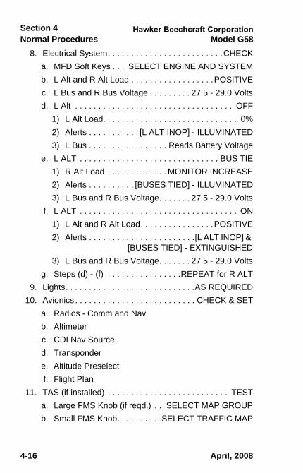
8. Electrical System. . . . . . . . . . . . . . . . . . . . . . . . .CHECKa. MFD Soft Keys . . . SELECT ENGINE AND SYSTEMb. L Alt and R Alt Load . . . . . . . . . . . . . . . . . .POSITIVEc. L Bus and R Bus Voltage . . . . . . . . . 27.5 - 29.0 Voltsd. L Alt . . . . . . . . . . . . . . . . . . . . . . . . . . . . . . . . . . OFF
1) L Alt Load. . . . . . . . . . . . . . . . . . . . . . . . . . . . . 0%2) Alerts . . . . . . . . . . . [L ALT INOP] - ILLUMINATED3) L Bus . . . . . . . . . . . . . . . . . Reads Battery Voltage
e. L ALT . . . . . . . . . . . . . . . . . . . . . . . . . . . . . . BUS TIE1) R Alt Load . . . . . . . . . . . . . MONITOR INCREASE2) Alerts . . . . . . . . . . [BUSES TIED] - ILLUMINATED3) L Bus and R Bus Voltage. . . . . . . 27.5 - 29.0 Volts
f. L ALT . . . . . . . . . . . . . . . . . . . . . . . . . . . . . . . . . . ON1) L Alt and R Alt Load. . . . . . . . . . . . . . . .POSITIVE2) Alerts . . . . . . . . . . . . . . . . . . . . . . .[L ALT INOP] &
[BUSES TIED] - EXTINGUISHED3) L Bus and R Bus Voltage. . . . . . . 27.5 - 29.0 Volts
g. Steps (d) - (f) . . . . . . . . . . . . . . . .REPEAT for R ALT9. Lights. . . . . . . . . . . . . . . . . . . . . . . . . . . .AS REQUIRED
10. Avionics . . . . . . . . . . . . . . . . . . . . . . . . . . CHECK & SETa. Radios - Comm and Navb. Altimeterc. CDI Nav Sourced. Transpondere. Altitude Preselectf. Flight Plan
11. TAS (if installed) . . . . . . . . . . . . . . . . . . . . . . . . . . TESTa. Large FMS Knob (if reqd.) . . SELECT MAP GROUPb. Small FMS Knob. . . . . . . . . SELECT TRAFFIC MAP
April, 2008
sec04.fm Page 16 Thursday, May 1, 2008 2:19 PM

Normal ProceduresSection 4
Model G58
4-17
Document Date
4-17
c. TEST Softkey. . . . . . . . . . . . . . . . . . . . . . . . . PRESS1) Test Pattern. . . . . . . . . . . . . . . . VERIFY ON MFD2) [TRAFFIC] . . . . . . . . . . . . . . . . . VERIFY ON PFD
d. Verify Voice Message . . . . . “Traffic Advisory System Test Passed”
e. ALT MODE. . . . . . . . . . . . . . . . . . SET AS DESIREDf. Small FMS Knob . . . SELECT DESIRED MAP PAGE
12. TAWS (if desired) (if installed) . . . . . . . . . . . . . . . .TESTa. Large FMS Knob (if reqd.) . . .SELECT MAP GROUPb. Small FMS Knob . . . . . . SELECT THE TAWS PAGEc. Press the MENU Keyd. Small FMS Knob . . . . . . . . . . SELECT “Test TAWS”e. Press ENT Keyf. Verify a white [TAWS TEST] is displayed on the PFD.
g. Verify the TAWS page turns black, a yellow [TAWSTEST] is displayed in the center of the page and awhite [TAWS TEST] is displayed in the lower rightcorner.
h. Verify “TAWS SYSTEM TEST, OK” is heard at theend of the test.
13. Standby Attitude Indicator. . . . . . . . . . . . . . . . . . CHECKa. Standby Battery . . . . . . . . . . . . CHECK IF DESIRED
(see OTHER NORMAL PROCEDURES)b. STBY PWR LED . . . . . . . . . . . . . . .EXTINGUISHEDc. Flag . . . . . . . . . . . . . . . . . . . . . . . . . . . . . . . PULLEDd. PULL-TO-CAGE Knob . . . . . . . . . . PULL TO ERECT
(release knob slowly)
The indicator may be damaged if the PULL-TO-CAGE knob is released with a snap.
April, 2008
sec04.fm Page 17 Thursday, May 1, 2008 2:19 PM

Normal Procedures Model G58Section 4
4 - 18
Document Date
4-18
14. Standby Altimeter . . . . . . . . . . . . . . . . . . . . . . . . . . SET15. Brakes . . . . . . . . . . . . . . . . . . . .RELEASE AND CHECK
Never taxi with a flat shock strut
BEFORE TAKEOFF (RUNUP) 1. Parking Brake . . . . . . . . . . . . . . . . . . . . . . . . . . . . . SET2. Seat Belts and Shoulder Harnesses . . . . . . . .CONFIRM
BUCKLED3. Engine Instruments . . . CHECK WITHIN OPER. LIMITS4. Flight Instruments . . . . . . . . . . . . . . . . . . . . . . . .CHECK5. Throttles . . . . . . . . . . . . . . . . . . . . . . . . . . . . 2200 RPM6. Propellers . . . . . . . . . . . . . . . . . . . . . . . . . . . EXERCISE
(to obtain 200 to 300 RPM drop)7. Throttles . . . . . . . . . . . . . . . . . . . . . . . . . . . . 1700 RPM8. Magnetos. . . . . . . . . . . . . . . . . . . . . . . . . . . . . . .CHECK
a. Variance between individual magnetos should notexceed 50 RPM
b. Maximum drop should not exceed 150 RPM9. Throttles . . . . . . . . . . . . . . . . . . . . . . . . . . . . 1500 RPM
10. Propellers . . . . . . . . . . . . . . . . . .FEATHERING CHECKa. Move the propeller controls past the detentb. Do not allow an RPM drop of more than 300 RPM on
either engine.
Failure to observe the RPM limits during theFEATHERING CHECK will impose high stresseson the propeller mechanisms, blade shanks andengines.
April, 2008
sec04.fm Page 18 Thursday, May 1, 2008 2:19 PM

Normal ProceduresSection 4
Model G58
4-19
Document Date
4-19
11. Electric Elevator Trim . . . . . . . . . . . . . . . . . . . . . CHECKa. Left and Right Segments . . . . . . . . . . . . . . ACTUATE
INDIVIDUALLY(verify there is no trim movement. Red PTRM illumi-nated on PFD if actuated for >4 sec.)
b. Left and Right Segments . . . ACTUATE TOGETHER (verify proper trim movement)
c. AP DISC Switch . . . . . . . . . . . . . . . .ACTUATE WITH TRIM IN MOTION (verify trim motion stops)
12. Trim. . . . . . . . . . . . . . . . . . . . . . . . . . . . . . . . . . . . . .SETa. Aileron and Rudder . . . . . . . . . . . . . . . . . . NEUTRALb. Elevator . . . . . . . . . . . . SET WITHIN GREEN BAND
13. Flaps . . . . . CHECK OPERATION, SET FOR TAKEOFF14. Flight Controls. . . .CHECK FREEDOM OF MOVEMENT
AND PROPER DIRECTION OF TRAVEL15. Doors and Windows . . . . . . . . . . . . . . . . . . . . .SECURE
• Cabin Door Lock Indicator. . . . . . . . . . CHECK CLOSED16. Fuel Selectors . . . . . . . . . . . . . . . . . . . . . . . . . . . . . . .ON
(feel for detent; confirm visually)17. Fuel Boost Pump . . . . . . . . . . . . . . . . . . . . . . . . . . .OFF
(if ambient temperature is 32°C or above, use LOWpressure boost)
18. Alerts/Messages . . EXTINGUISHED OR CONSIDERED19. PFD Attitude and Heading . . . . . . . . . . . . . . . .NORMAL20. GPS Position . . . . . . . . . . . . . . . . . . . . . . . . . . . . VALID
(’LOI’ not annunciated on HSI)21. Standby Attitude Indicator. . . . . .ERECT AND NORMAL22. Parking Brake . . . . . . . . . . . . . . . . . . . . . . . . . RELEASE
April, 2008
sec04.fm Page 19 Thursday, May 1, 2008 2:19 PM

Normal Procedures Model G58Section 4
4 - 20
Document Date
4-20
BEFORE TAKEOFF (FINAL ITEMS)1. Ice Protection Systems . . . . . . . . . . . . . .AS REQUIRED2. Lights. . . . . . . . . . . . . . . . . . . . . . . . . . . .AS REQUIRED3. Transponder Code . . . . . . . . . . . . . . . . .CONFIRM SET4. Rotation Speed . . . . . . . . . . . . . . . . . . . . . . . .CONFIRM
(for 5500 lbs., Flaps Up = 85 KTS)
TAKEOFF 1. Take-off Power . . . . . . . . . . . . . . . . . . . . . . . . . . . . SET
a. Throttles . . . . . . . . . . . . . . . . . . . . . FULL FORWARDb. Propellers . . . . . . . . . . . . . . . . . . . . . . . . . HIGH RPMc. Mixtures . . . . . . . . . . . . SET FUEL FLOW AT CYAN
CLIMB FUEL FLOW MARKER2. Brakes . . . . . . . . . . . . . . . . . . . . . . . . . . . . . . .RELEASE3. Instruments . . . . . . . . . . . . . . . . . . . . . . . . . . . . .CHECK
(MAP, RPM, Fuel Flow, Oil Temp/Press)4. Rotation Speed . . . . . . . . . . . . . . . . . . . . . . . . .ROTATE5. Landing Gear
(when positive R/C established) . . . . . . . . . . RETRACT
CLIMB 1. Power . . . . . . . . . . . . . . . . . . . . . . . . . . . . . . . . . . . SET
a. Throttles . . . . . . . . . . . . . . . . . . . . . FULL FORWARDb. Propellers . . . . . . . . . . . . . . . MCP Climb - 2700 RPM
Cruise Climb - 2500 RPMc. Prop Sync . . . . . . . . . . . . . . . . . . . . . . . . . . . . . . . ONd. Mixtures . . . . . . . . . . . . . MAINTAIN FUEL FLOW AT
CYAN CLIMB FUEL FLOW MARKER
NOTEThe fuel flow marker will not revert to the CruiseClimb schedule until the RPM is initially reducedto 2490 or below. The Cruise Climb schedule willbe available up to 2530 RPM.
April, 2008
sec04.fm Page 20 Thursday, May 1, 2008 2:19 PM

Normal ProceduresSection 4
Model G58
4-21
2. Cowl Flaps . . . . . . . . . . . . . . . . . . . . . . . AS REQUIRED3. Airspeed . . . . . . . . . . . . . . . 105 KTS FOR MCP CLIMB
136 KTS FOR CRUISE CLIMB4. Engine Temperatures . . . . . . . . . . . . . . . . . . .MONITOR5. Fuel Boost Pump . . . . . . . . . . . . . . . . . . AS REQUIRED
Engine roughness, fuel flow fluctuation orlow fuel flow can occur when climbing onhot days. These can be eliminated byswitching the fuel boost pump from OFF toLO and leaning the fuel flow to the cyanclimb fuel flow marker.
The cyan climb fuel flow marker on the fuel flow indicator isprogrammed to follow the schedule noted below when climbingat 2700 RPM. When climbing at 2500 RPM, the fuel flowmarker is programmed to follow a schedule which is 2 GPHless than that shown below.
PRESSURE ALTITUDE (FT) CYAN CLIMB FUEL FLOWMARKER @ 2700 RPM*
(GPH)SL 26.6
2000 25.94000 24.36000 22.88000 21.8
10,000 20.912,000 20.014,000 19.116,000 18.317,000 18.0
* Subtract 2 GPH when cruise climbing at 2500 RPM.
April, 2008
58-590000-67A10_sec04 - BeechcraftCopy.fm Page 21 Friday, August 9, 2013 3:33 PM
Normal Procedures Model G58Section 4
4-22
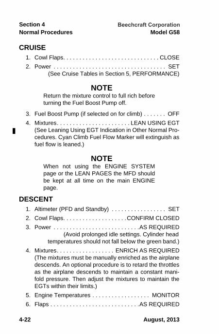
CRUISE 1. Cowl Flaps. . . . . . . . . . . . . . . . . . . . . . . . . . . . . . CLOSE2. Power . . . . . . . . . . . . . . . . . . . . . . . . . . . . . . . . . . . SET
(See Cruise Tables in Section 5, PERFORMANCE)
NOTEReturn the mixture control to full rich beforeturning the Fuel Boost Pump off.
3. Fuel Boost Pump (if selected on for climb) . . . . . . . OFF4. Mixtures. . . . . . . . . . . . . . . . . . . . . . . LEAN USING EGT
(See Leaning Using EGT Indication in Other Normal Pro-cedures. Cyan Climb Fuel Flow Marker will extinguish asfuel flow is leaned.)
NOTEWhen not using the ENGINE SYSTEMpage or the LEAN PAGES the MFD shouldbe kept at all time on the main ENGINEpage.
DESCENT 1. Altimeter (PFD and Standby) . . . . . . . . . . . . . . . . . SET2. Cowl Flaps. . . . . . . . . . . . . . . . . . . .CONFIRM CLOSED3. Power . . . . . . . . . . . . . . . . . . . . . . . . . . .AS REQUIRED
(Avoid prolonged idle settings. Cylinder head temperatures should not fall below the green band.)
4. Mixtures. . . . . . . . . . . . . . . . . . ENRICH AS REQUIRED(The mixtures must be manually enriched as the airplanedescends. An optional procedure is to retard the throttlesas the airplane descends to maintain a constant mani-fold pressure. Then adjust the mixtures to maintain theEGTs within their limits.)
5. Engine Temperatures . . . . . . . . . . . . . . . . . . MONITOR6. Flaps . . . . . . . . . . . . . . . . . . . . . . . . . . . .AS REQUIRED
August, 2013
58-590000-67A10_sec04 - BeechcraftCopy.fm Page 22 Friday, August 9, 2013 3:33 PM

Normal ProceduresSection 4
Model G58
4-23
Document Date
4-23
7. Windshield Defroster. . . . . . . . . . . . . . . . AS REQUIRED (ON before descent into warm, moist air)
8. Descent Speed . . . . . . . . . . . . . . . . . .RECOMMENDED16,000 to 13,000 ft . . . . . . . . . . . . . . . . . . . . . . 160 KTSBelow 13,000 ft . . . . . . . . . . . . . . . . . . . . . . . . . 170 KTS
BEFORE LANDING 1. Seat Belts and Shoulder Harnesses. . . . . . .FASTENED2. Seat Backs . . . . . . . . . . . . . . POSITION FOR LANDING3. Fuel Selector Valves. . . . . . . . . . . . . . . . . . .CHECK ON
(feel for detent; confirm visually)4. Fuel Boost Pumps . . . . . . . . . . .OFF OR LOW AS PER
AMBIENT TEMPERATURE5. Cowl Flaps . . . . . . . . . . . . . . . . . . . . . . . AS REQUIRED6. Mixture Controls . . . . . . . . . . . . . . . . . . . . . . FULL RICH
(or as required by field elevation) 7. Landing Gear (152 kts or below). . DOWN AND CHECK8. Landing Lights . . . . . . . . . . . . . . . . . . . . AS REQUIRED9. Propellers . . . . . . . . . . . . . . . . . . . . . . . . . . . HIGH RPM
NORMAL LANDING1. Flaps (122 kts or below) . . . . . . . . . . . . . . .FULL DOWN2. Airspeed . . ESTABLISH NORMAL APPROACH SPEED3. Yaw Damp . . . . . . . . . . . . . . . . . . . . . . . . . . . . . . . .OFF
BALKED LANDING 1. Throttles and Propellers . . . . . . . . . . . FULL FORWARD2. Airspeed . . . . . . . . . . . . . . . . . . . . . . . . . . . . . . . 95 KTS3. Flaps . . . . . . . . . . . . . . . . . . . . . . . . . . . . . . . . . . . . . .UP4. Landing Gear . . . . . . . . . . . . . . . . . . . . . . . . .RETRACT5. Cowl Flaps . . . . . . . . . . . . . . . . . . . . . . . AS REQUIRED
April, 2008
sec04.fm Page 23 Thursday, May 1, 2008 2:19 PM

Normal Procedures Model G58Section 4
4 - 24
Document Date
4-24
AFTER LANDING 1. Landing, Taxi and Strobe Lights . . . . . . .AS REQUIRED2. Flaps . . . . . . . . . . . . . . . . . . . . . . . . . . . . . . . . . . . . . UP3. Cowl Flaps. . . . . . . . . . . . . . . . . . . . . . . . . . . . . . . OPEN4. Trim Tabs . . . . . . . . . . . . . . . . . RESET AS REQUIRED5. Fuel Boost Pumps . . . . . . . . . . . . . . . . . .AS REQUIRED
SHUTDOWN AND SECURING 1. Parking Brake . . . . . . . . . . . . . . . . . . . . . . . . . . . . . SET2. Avionics . . . . . . . . . . . . . . . . . . . . . . . . . . . . . . . . . . OFF
a. MFD . . . . . . . . . . . . . . . . . . . . . . . . EXTINGUISHEDb. PFD . . . . . . . . . . . VERIFY REVERSIONARY MODE
3. Electrical Equipment . . . . . . . . . . . . . . . . . . . . . . . . OFF4. Throttles . . . . . . . . . . . . . . . . . . . . . . . . . . . . 1000 RPM5. Fuel Boost Pumps . . . . . . . . . . . . . . . . . . . . . . . . . . OFF6. Mixture Controls . . . . . . . . . . . . . . . . . . . . . . . CUT OFF7. Magnetos. . . . . . . . . . . . . . . . . . . . . . . . . . . . . . . . . OFF
(after engines stop)8. L ALT and R ALT. . . . . . . . . . . . . . . . . . . . . . . . . . . OFF9. L BAT and R BAT . . . . . . . . . . . . . . . . . . . . . . . . . . OFF
10. Standby Attitude Indicator (if desired) . . . . . . . . .CHECK EMERGENCY MODE (See OTHER NORMAL PROCEDURES)
11. Control Locks . . . . . . . . . . . . . . . . . . . . . . . . . . INSTALL12. Wheel Chocks . . . . . . . . . . . . . . . . . . . . . . . . . . INSTALL13. Parking Brake . . . . . . . . . . . . . . . . . . . . . . . . .RELEASE
NOTEInduction air scoop covers, included in the loosetools and accessories, are to prevent foreignmatter from entering the air scoops while the air-plane is parked.
April, 2008
sec04.fm Page 24 Thursday, May 1, 2008 2:19 PM

Normal ProceduresSection 4
Model G58
4-25
Document Date
4-25
OTHER NORMAL PROCEDURESEXTERNAL POWER The following precautions shall be observed using externalpower:
1. Batteries must be installed in the airplane. This protectsthe voltage regulators and associated equipment fromvoltage transients (power fluctuations).
2. The airplane has a negative ground system. Connect thepositive lead of the external power unit to the positiveterminals of the airplane’s external power receptacle andthe negative lead of the external power unit to the nega-tive terminal of the external power receptacle.
3. In order to prevent arcing, ensure external power unit isoff while the connection is being made.
ENGINE STARTING USING EXTERNAL POWER
1. L BAT and R BAT . . . . . . . . . . . . . . . . . . . . . . . . . . .OFF2. L ALT and R ALT . . . . . . . . . . . . . . . . . . . . . . . . . . .OFF3. Avionics Master Switch . . . . . . . . . . . . . . . . . . . . . . .OFF4. Electrical Equipment . . . . . . . . . . . . . . . . . . . . . . . . .OFF5. External Power Source . . . . . SET OUTPUT, THEN OFF
(27.0 to 28.5 volts)6. External Power Source . . . . . . . . . . . . . . . . . CONNECT7. L BAT and R BAT . . . . . . . . . . . . . . . . . . . . . . . . . . . .ON8. External Power Source . . . . . . . . . . . . . . . . . . . . . . . .ON9. Alerts. . . . . . . . . . . . . . . . [BUSES TIED] ILLUMINATED
10. Right Engine . . . . . . . . . . . . . . . . . . . . . . START USING NORMAL PROCEDURES
11. External Power Source . . OFF AFTER ENGINE START12. Alerts. . . . . . . . . . . . . . .[BUSES TIED] EXTINGUISHED13. External Power Source . . . . . . . . . . . . . . DISCONNECT
April, 2008
sec04.fm Page 25 Thursday, May 1, 2008 2:19 PM

Normal Procedures Model G58Section 4
4 - 26
Document Date
4-26
14. L ALT and R ALT. . . . . . . . . . . . . . . . . . . . . . . . . . . . ON15. Left Engine . .START USING NORMAL PROCEDURES16. L and R ALT LOAD . . . . . . . . . . . . . . . . . . . . MONITOR
STANDBY ATTITUDE INDICATORAFTER STARTING
After allowing the gyro to spin up for approximately oneminute, the PULL-TO-CAGE knob must be pulled fully out andheld momentarily until the display stabilizes, then releasedslowly.
The indicator may be damaged if knob isreleased with a “snap”.
BEFORE TAKEOFF
Standby Battery Check
The status of the standby battery may be checked as follows:
1. STBY PWR Button . . . . . . . PRESS AND HOLD UNTIL STBY PWR LED STARTS FLASHING (places battery in one minute test mode)
2. Green Test LED . . . . . . . . . . . . . . . . . . . ILLUMINATED3. Red Test LED . . . . . . . . . . . . . . . . . . . EXTINGUISHED4. Emergency LED Lighting. . . . . . . . . . . . . ILLUMINATED5. Amber Standby Power LED . . . . . . . . EXTINGUISHED
(after approx. 1 minute)6. Green Test LED . . . . . . . . . . . . . . . . . EXTINGUISHED
April, 2008
sec04.fm Page 26 Thursday, May 1, 2008 2:19 PM
Normal ProceduresSection 4
Model G58
4-27
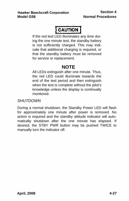
If the red test LED illuminates any time dur-ing the one minute test, the standby batteryis not sufficiently charged. This may indi-cate that additional charging is required, orthat the standby battery must be removedfor service or replacement.
NOTEAll LEDs extinguish after one minute. Thus,the red LED could illuminate towards theend of the test period and then extinguishwhen the test is complete without the pilot’sknowledge unless the display is continuallymonitored.
SHUTDOWN
During a normal shutdown, the Standby Power LED will flashfor approximately one minute after power is removed. Noaction is required and the standby attitude indicator will auto-matically shutdown after the one minute has elapsed. Ifdesired, the STBY PWR button may be pushed TWICE tomanually turn the indicator off.
April, 2008
58-590000-67A8_sec04.fm Page 27 Monday, May 16, 2011 8:56 AM

Normal Procedures Model G58Section 4
4-28
NOTEA momentary pause must occur betweeneach push of the STBY PWR button. If thesecond push of the button occurs tooquickly, it will not be recognized. If the pro-cessor detects only one push of the STBYPWR button the standby battery will belatched on and continue to power the indi-cator. This will cause the standby battery tocompletely drain if not turned off by a sec-ond push of the button. If the standby bat-tery is allowed to completely drain, it willhave to be removed and serviced prior tothe next flight. The airplane power will notadequately recharge a completely drainedbattery.
Emergency Mode
The emergency mode may be checked during shutdown afterall power has been removed from the airplane as follows:
1. L BAT and R BAT . . . . . . . . . . . . . . . . . . . . . . . . . . OFF2. Amber Standby Power LED . . . . . . . . . . . . . FLASHING3. STBY PWR Button . . . . . . . . . . . . . . . . . PRESS ONCE
(latches standby battery on)• Gyro Warning Flag. . . . . . . . . . . . . . . . . . OUT OF VIEW• Amber Standby Power LED. . . . . . . . . EXTINGUISHED
4. STBY PWR Button . . . . . . . . . . . . . . . . . PRESS ONCE (disconnects standby battery)
• Gyro Warning Flag. . . . . . . . . . . . . . . . . . . . . . . IN VIEW5. R BAT . . . . . . . . . . . . . . . . . . . . . . . . . . . . . . . . . . . . ON
• Gyro Warning Flag. . . . . . . . . . . . . . . . . . OUT OF VIEW
June, 2011
58-590000-67A8_sec04.fm Page 28 Monday, May 16, 2011 8:56 AM

Normal ProceduresSection 4
Model G58
4-29
6. R BAT . . . . . . . . . . . . . . . . . . . . . . . . . . . . . . . . . . . .OFF• Amber Standby Power LED . . . . . . . . . .FLASHES FOR
ONE MINUTE, THEN EXTINGUISHES7. Gyro Warning Flag . . . . . . . . . . . . . . . . . . . . . . IN VIEW
LEANING USING THE EXHAUST GAS TEMPERA-TURE (EGT) INDICATIONA thermocouple-type exhaust gas temperature (EGT) probe ismounted in each cylinder exhaust. All probes interface with theEngine/Airframe Unit (GEA 71). The indicators are calibratedin degrees Celsius. Use the EGT system to lean the fuel/airmixture when cruising at 2500 rpm and 25 in. Hg manifoldpressure power setting or less in the following manner:
See the following information in Section 5, PERFORMANCE:• MANIFOLD PRESSURE vs RPM graph for leaning limi-
tations• CRUISE POWER SETTING tables
The EIS Lean page is found on the MFD.1. ENGINE Softkey . . . . . . . . . . . . . . . . . . . . . . . . . PRESS2. LEAN Softkey . . . . . . . . . . . . . . . . . . . . . . . . . . . PRESS
a. Rich of Peak: Slowly lean the mixture and note thefirst cylinder EGT to peak. Then enrich the mixture tothe desired cruise mixture. Enriching the mixture isreferred to as operation on the rich side of peak EGT.
b. Lean of Peak: Slowly lean the mixture and note thelast cylinder EGT to peak. Further lean the mixture tothe desired cruise mixture. Further leaning is referredto as operation on the lean side of peak EGT.
June, 2011
58-590000-67A9_sec04.fm Page 29 Wednesday, April 25, 2012 1:43 PM

Normal Procedures Model G58Section 4
4-30
3. The engine should not be operated closer to peak EGTthan 20°C (rich side or lean side) as indicated on theMANIFOLD PRESSURE vs RPM graph (Section 5,PERFORMANCE).
4. If engine roughness is encountered operating at lowerpower settings on the lean side of peak, enrich the mix-ture slightly for smooth engine operation.
5. If required fuel flows cannot be achieved when leaning tothe rich side of peak, switch the fuel boost pump to LO,then lean as required.
6. Changes in altitude and power settings require the peakEGT to be rechecked and the mixture reset.
7. MFD Softkeys . . . . .RETURN TO MAIN ENGINE PAGE
NOTEA Lean Assist function is available throughthe Garmin software utilizing the CYL SLCTand ASSIST Softkeys. Reference GarminCockpit Reference Guide for details on theprocedure.
MONITORING ENGINE SYSTEMS (OIL, FUEL,ELECTRICAL)The Engine Systems page is found on the MFD.
1. ENGINE Soft Key . . . . . . . . . . . . . . . . . . . . . . . . PRESS2. SYSTEM Soft Key . . . . . . . . . . . . . . . . . . . . . . . . PRESS3. MFD Softkeys . . . . .RETURN TO MAIN ENGINE PAGE
April, 2012
58-590000-67A9_sec04.fm Page 30 Wednesday, April 25, 2012 1:43 PM

Normal ProceduresSection 4
Model G58 Baron
P/N 58-590000-67TC1 Rev 1June, 2006 3 of 4
NORMAL PROCEDURES
AVIONICS
AUTOPILOT/FLIGHT DIRECTORGENERAL
NOTEIf above 150 KTS, operation in the PITmode can result in nuisance pitch pulsingwhen using the NOSE-UP or NOSE-DOWNcommand keys. Transition to ALT, FLC orVS mode prior to using NOSE-UP or NOSE-DOWN keys. With the autopilot engaged,recommended climb or descent rate is 800fpm or less.
ts93910
Rectangle

ts93910
Rectangle

Normal ProceduresSection 4
Model G58
4-31
MONITORING THE CHTS AND EGTS
Specific EGT and CHT values for each cylinder are found onthe MFD.
1. ENGINE Soft Key . . . . . . . . . . . . . . . . . . . . . . . . PRESS2. LEAN Soft Key . . . . . . . . . . . . . . . . . . . . . . . . . . PRESS3. CYL SLCT Soft Key . . . . . . . . . . . . . . . . . . . . . . PRESS
(Each press of the key cycles the display to the next cyl-inder. The selected cylinder display number changescolor from white to cyan and the digital displays show theabsolute temperature and deviation from Peak tempera-ture for the selected cylinder.)
4. MFD Softkeys . . . . . RETURN TO MAIN ENGINE PAGE
AVIONICSAUTOPILOT/FLIGHT DIRECTORGENERAL
It is the responsibility of the Pilot to monitorthe autopilot when it is engaged. The pilotshould be prepared to immediately discon-nect the autopilot and take prompt correc-tive action in the event of unexpected orunusual autopilot behavior.
Do not attempt to manually fly the airplane with the autopilotengaged except when using the Control Wheel Steering(CWS) button. The autopilot pitch servo will oppose pilot pitchinputs and will trim the elevator in the opposite direction of thepilot input. This could lead to a significant out-of-trim conditionin the pitch axis. Disconnect the autopilot using the AP DISCswitch, the left side of the trim switch, or the AP key if manualcontrol is desired.
June, 2011
58-590000-67A8_sec04.fm Page 31 Monday, May 16, 2011 8:56 AM

Normal Procedures Model G58Section 4
4-32
The pilot must use proper autopilot modes and proper enginepower settings to ensure that airplane speed is maintainedbetween 90 KTS and 210 KTS. Operation in the pitch (PIT) orvertical speed (VS) modes below 90 KTS can result in a stall. Ifan inadvertent stall is encountered as indicated by the stallwarning horn, airframe buffeting, or loss of control effective-ness, disconnect the autopilot using the AP DISC switch andmanually return the airplane to stabilized flight prior to re-engaging the autopilot.
AUTOPILOT/ FLIGHT DIRECTOR PROCEDURES
The following are basic guidelines for operation of the autopilotand Flight Director. They are one way, but not necessarily theonly way; of operating the AFCS. See Section 2, LIMITA-TIONS; Section 3, EMERGENCY PROCEDURES; Section 3A,ABNORMAL PROCEDURES; Section 7, SYSTEMSDESCRIPTION; and the Garmin G1000 Cockpit ReferenceGuide or G1000 Pilot's Guide for more information.
Yaw Damp (With Autopilot Off)
To Engage the Yaw Damper:
1. YD Key . . . . . . . . . . . . . . . . . . . . . . . . . . . . . . . . PRESS Green [YD] Displayed
To disengage the YD use one of the following methods. Thegreen [YD] will change to a black [YD] on a yellow background,flash for 5 seconds, then extinguish.
1. AP DISC Switch . . . . . . . . . . . . . . . . . . . . . . . . . PRESS
(or)
2. YD Key . . . . . . . . . . . . . . . . . . . . . . . . . . . . . . . . PRESS
June, 2011
58-590000-67A8_sec04.fm Page 32 Monday, May 16, 2011 8:56 AM

Normal ProceduresSection 4
Model G58
4-33
Engaging the Autopilot (90 - 210 KTS)
1. AP Key . . . . . .PRESS TO ENGAGE AUTOPILOT & YD green [ROL], [AP], [YD], [PIT], & white [ALT] Displayed
2. ALT Key . . . . .PRESS TO HOLD EXISTING ALTITUDE [PIT] & [ALT] are replaced by a green [ALT XXXXXFT]
3. HDG Knob (if required) . . . . . .SET DESIRED HEADING4. HDG Key. . . . . . . . . . . . . . . . . . . . . . . . . . . . . . . PRESS
[HDG] replaces [ROL]5. CRS Knob (if required) . . . . . . SET DESIRED COURSE6. NAV Key (if required) . . . . . . . . . . . . . . . . . . . . . PRESS
[VOR] or [GPS] or [LOC] Displayed
Disengaging the Autopilot or Autopilot & Yaw Damper
When the autopilot is manually disengaged the green [AP] willchange to a black [AP] on a yellow background, flash for 5 sec-onds, then extinguish, and a 2-second aural alert will sound.The [YD] will also change color and flash if it disconnects
To disengage only the AP and leave the FD and YD engageduse one of the following methods:
1. Left Side of Trim Switch . . . . . . . . . . . . . . . . . ACTUATE
(or)
2. AP Key . . . . . . . . . . . . . . . . . . . . . . . . . . . . . . . . PRESS
To disengage the AP and YD and leave the FD engaged:
1. AP DISC Switch . . . . . . . . . . . . . . . . . . . . . . . . . PRESS
June, 2011
58-590000-67A8_sec04.fm Page 33 Monday, May 16, 2011 8:56 AM
Normal Procedures Model G58Section 4
4-34
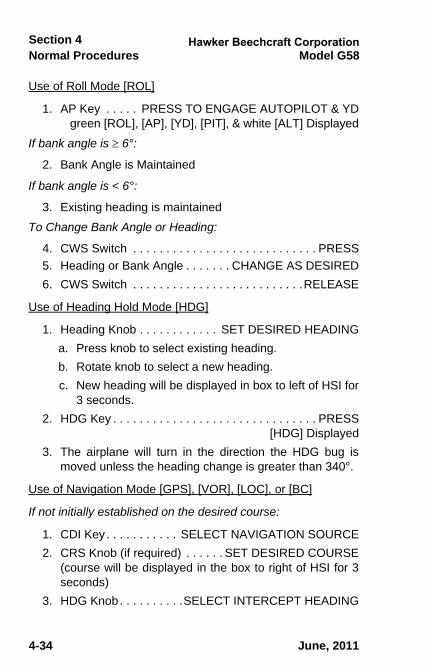
Use of Roll Mode [ROL]
1. AP Key . . . . . PRESS TO ENGAGE AUTOPILOT & YD green [ROL], [AP], [YD], [PIT], & white [ALT] Displayed
If bank angle is 6°:
2. Bank Angle is Maintained
If bank angle is < 6°:
3. Existing heading is maintained
To Change Bank Angle or Heading:
4. CWS Switch . . . . . . . . . . . . . . . . . . . . . . . . . . . . PRESS5. Heading or Bank Angle . . . . . . . CHANGE AS DESIRED6. CWS Switch . . . . . . . . . . . . . . . . . . . . . . . . . .RELEASE
Use of Heading Hold Mode [HDG]
1. Heading Knob . . . . . . . . . . . . SET DESIRED HEADINGa. Press knob to select existing heading.b. Rotate knob to select a new heading.c. New heading will be displayed in box to left of HSI for
3 seconds.2. HDG Key . . . . . . . . . . . . . . . . . . . . . . . . . . . . . . . PRESS
[HDG] Displayed3. The airplane will turn in the direction the HDG bug is
moved unless the heading change is greater than 340°.
Use of Navigation Mode [GPS], [VOR], [LOC], or [BC]
If not initially established on the desired course:
1. CDI Key . . . . . . . . . . . SELECT NAVIGATION SOURCE2. CRS Knob (if required) . . . . . . SET DESIRED COURSE
(course will be displayed in the box to right of HSI for 3seconds)
3. HDG Knob. . . . . . . . . .SELECT INTERCEPT HEADING
June, 2011
58-590000-67A8_sec04.fm Page 34 Monday, May 16, 2011 8:56 AM

Normal ProceduresSection 4
Model G58
4-35
4. HDG Key. . . . . . . . . . . . . . . . . . . . . . . . . . . . . . . PRESS [HDG] Displayed
5. NAV Key . . . . . . . . . . . . . . . . . . . . . . . . . . . . . . . PRESS
If CDI Deviation is > 1Dot:
a. [GPS], [VOR], [LOC], or [BC] . . . . . . . . . DISPLAYED IN WHITE
When CDI Deviation is 1 Dot:
b. [GPS], [VOR], [LOC], or [BC] . . . . . . . . . DISPLAYED IN GREEN
Use of Altitude Preselect
1. ALT Knob . . . . ROTATE TO SET DESIRED ALTITUDE(Desired altitude displayed inaltitude reference box abovealtitude display)
2. PIT, VS, or FLC Mode . . . . . . . . . SET TO INTERCEPT ALTITUDE
a. At 1000 feet from desired altitude, the altitude in thereference box will change from cyan digits on a blackbackground to black digits on a cyan background,and the box will flash for 5 seconds.
b. At 300 feet from the desired altitude, a cyan altitudereference bug will be visible on the left side of the alti-tude display opposite the desired altitude.
c. At 200 feet from the desired altitude, the altitude inreference box returns to cyan digits on a black back-ground, will flash for 5 seconds, and a tone willsound.
d. When established on the desired altitude, the altitudereference bug will be aligned with the indicated alti-tude. The white [ALT] in the AFCS Status Bar will bereplaced with a green [ALT XXXXXFT]. The [ALT] willflash for 10 seconds.
June, 2011
58-590000-67A8_sec04.fm Page 35 Monday, May 16, 2011 8:56 AM
Normal Procedures Model G58Section 4
4-36
e. If the indicated altitude deviates more than ± 200 feet,the altitude reference box will change to yellow digitson a black background and will flash for 5 seconds. Atone will be heard. The yellow display will remain untilthe deviation is corrected or the desired altitude ischanged.
Use of the Pitch Mode (PIT)
1. ALT Knob . . . . .SET DESIRED LEVEL-OFF ALTITUDEa. Preset Altitude is displayed in window above the
altimeter display.2. Deselect other vertical modes (VS or FLC), if required.3. Green [PIT] and White [ALT] . . . . . . . . . . . . DISPLAYED
IN AFCS STATUS BAR4. NOSE UP or NOSE DN Key . .PRESS AS REQ TO SET
CLIMB OR DESCENT PITCH ATTITUDE (each press changes pitch by 0.5 degrees)
(or)
5. CWS Switch . . . . . . . . . . . . PRESS AND HOLD WHILE ADJUSTING PITCH, THEN RELEASE (Pitch reference will change to that which exists when switch is released.)
6. Power . . . . . . . . . . . . . . . . . . . . . . . . . . .AS REQUIRED7. Upon Reaching the Preset Altitude, the green [PIT] and
white [ALT] will be replaced by a green [ALT] and[XXXXXFT] and the green [ALT] will flash 10 secondsand then become steady.
June, 2011
58-590000-67A8_sec04.fm Page 36 Monday, May 16, 2011 8:56 AM
Normal ProceduresSection 4
Model G58
4-37
Use of Altitude Hold Mode [ALT]
To Maintain a desired altitude:1. ALT Key . . . . . . . . . . . . . . . . . . . . . . . . . . . . . . . PRESS
Green [ALT XXXXXFT] Displayed
To change the selected altitude:
2. CWS Switch . . . . . . . . . . . . . . . . . . PRESS AND HOLD3. Airplane Altitude . . . . . . . . . . . . CHANGE AS DESIRED4. CWS Switch . . . . . . . . . . . . . . . . . . . . . . . . . . RELEASE
(new altitude will be displayed next to [ALT])5. Barometric Changes . . . . . . . . .AIRPLANE WILL CLIMB
OR DESCEND TO MAINTAIN SELECTED ALTITUDE
Use of the Vertical Navigation Mode [VNV] (if installed)
NOTEVertical navigation will only function when thenavigation source is GPS. The airplane’s head-ing must be within 75 degrees of the desiredGPS course and within 10 NM cross track errorin order for VNAV to function.VNAV functions only for enroute and terminaldescents. Vertical navigation is not available dur-ing climbs or descents between the finalapproach fix (FAF) and the missed approachpoint (MAP).
For VNAV Descent
1. ALT knob . . . . . . . . . . . . . . . SET DESIRED ALTITUDE2. VNV . . . . . .PRESS WITHIN 5 MINUTES OF THE TOD3. 1 Minute Prior to TOD. . . . . . . . . . . . . . . . . . . . .VERIFY
a. VNAV target altitude on PFD.b. Vertical Deviation Indicator (VDI) on PFD.
June, 2011
58-590000-67A8_sec04.fm Page 37 Monday, May 16, 2011 8:56 AM

Normal Procedures Model G58Section 4
4-38
NOTEIf the VNV softkey is pressed more than 5minutes before the top of descent (TOD) orthe altitude preselect is not reset to a loweraltitude, VPTH will begin to flash inversevideo (white/black) when the aural “VerticalTrack” alert sounds 1 minute prior to TOD.Pressing the VNV softkey and/or resettingthe altitude preselect to a lower altitudecancels the flashing VPTH and the autopi-lot will capture and track the vertical profile.If the VNV softkey is not pressed, or thealtitude preselect is not reset to a lower alti-tude, VPTH stops flashing at the TOD andthe airplane will remain in ALT mode andnot descend.
4. At TOD . . . . . . . . . . . . . . . . . . . . . . . . . . . . . . . VERIFYa. Green [VPTH] in the AFCS status window on PFD.b. White [ALTS] or [ALTV] in the AFCS armed window
on PFD.c. Airplane tracks vertical path.
5. Power . . . . . . . . . . . . . . . . . . . . . . . . . . .AS REQUIRED
For Vertical DIRECT TO
1. ALT knob . . . . . . . . . . . . . . . . SET DESIRED ALTITUDE2. VNV Softkey . . . . . . . . . . . . . . . . . . . . . . . . . . . . PRESS
3. VNV D Softkey on MFD flight plan page . . . . . PRESS
4. Desired Waypoint . . . . . . . . . SELECT AND ACTIVATE
June, 2011
58-590000-67A8_sec04.fm Page 38 Monday, May 16, 2011 8:56 AM
Normal ProceduresSection 4
Model G58
4-39
Use of the Vertical Speed Mode [VS]
1. ALT Knob . . . . .SET DESIRED LEVEL-OFF ALTITUDEa. Preset Altitude is displayed in window above the
altimeter display.
NOTEIf the Flight Director is in Altitude Hold(green [ALT XXXXXFT] displayed in theAFCS status bar), the desired altitude mustbe set either above or below the AltitudeHold value for the VS mode to function.
2. VS Key . . . . . . . . . . . . . . . . . . . . . . . . . . . . . . . . PRESSa. Green [VS] and green current vertical speed
[XXXXFPM] displayed in AFCS status bar.b. Current vertical speed displayed in window above (for
a climb) or below (for a descent) the Vertical Speeddisplay.
c. Cyan VS Reference bug displayed on left side of VSdisplay.
d. White [ALT] Displayed in AFCS Status Bar.3. NOSE UP or NOSE DN Key. . . . . . . . . PRESS AS REQ
TO SET CLIMB OR DESCENT VS (each press changes VS by 100 fpm)
(or)
4. CWS Switch . . . . . . . . . . . . . . . . . . PRESS AND HOLD WHILE ADJUSTING PITCH TO CHANGE VS, THEN RELEASE (VS reference will change to that which exists when switch is released.)
5. Power . . . . . . . . . . . . . . . . . . . ADJUST AS REQUIRED FOR DESIRED AIRSPEED
June, 2011
58-590000-67A8_sec04.fm Page 39 Monday, May 16, 2011 8:56 AM

Normal Procedures Model G58Section 4
4-40
6. Maximum and minimum VS references are 1500 fpm R/C and -3000 fpm R/S.
NOTEThe VS pointer will only indicate a maxi-mum of -2000 FPM; however, the digits inthe pointer will continue to indicate the ver-tical speed up to -3000 FPM.
7. Upon Reaching the Preset Altitude, the green [VS],[XXXXFPM], and white [ALT] will be replaced by a green[ALT] and [XXXXXFT], and the green [ALT] will flash for10 seconds and then become steady.
Use of the Flight Level Change Mode [FLC]
1. ALT Knob . . . . .SET DESIRED LEVEL-OFF ALTITUDEa. Preset Altitude is displayed in window above the
altimeter display.
NOTEIf the Flight Director is in Altitude Hold(green [ALT XXXXXFT] displayed in theAFCS status bar), the desired altitude mustbe set either above or below the AltitudeHold value for the FLC mode to function.
2. FLC Key . . . . . . . . . . . . . . . . . . . . . . . . . . . . . . . PRESSa. Green [FLC] and green current airspeed [XXXKT] dis-
played in AFCS status bar.b. Current airspeed displayed in window above the air-
speed display.c. Cyan airspeed reference bug displayed on right side
of the airspeed display.d. White [ALT] Displayed in AFCS Status Bar.
June, 2011
58-590000-67A8_sec04.fm Page 40 Monday, May 16, 2011 8:56 AM

Normal ProceduresSection 4
Model G58
4-41
3. NOSE UP or NOSE DN Key. . . . . . . . . PRESS AS REQ TO SET CLIMB OR DESCENT SPEED (each press changes speed by 1 knot)
(or)
4. CWS Switch . . . . . . . . . . . . PRESS AND HOLD WHILE ADJUSTING PITCH TO CHANGE AIRSPEED, THEN RELEASE (FLC airspeed reference will change to the airspeed that exists when switch is released.)
5. Power . . . . . . . . . . . . . . . . . . . ADJUST AS REQUIRED FOR DESIRED R/C OR R/S
6. Maximum and minimum FLC reference airspeeds are210 and 90 Kts.
7. Upon Reaching the Preset Altitude, the green [FLC],[XXXKT], and white [ALT] will be replaced by a green[ALT] and [XXXXXFT], and the green [ALT] will flash for10 seconds and then become steady.
APPROACH PROCEDURES
VOR or ILS Approaches [VAPP] or [LOC] & [GS]
1. CDI Key . . . . . . . . . . . . . . . SELECT VOR 1 OR VOR 22. CRS Knob. . . . . . . . . . . . . . .SET REQUIRED COURSE3. HDG Knob . . . . . . . . . SELECT INTERCEPT HEADING 4. HDG Key. . . . . . . . . . . . . . . . . . . . . . . . . . . . . . . PRESS
[HDG] Displayed5. APR Key . . . . . . . . . . . . . . . . . . . . . . . . . . . . . . . PRESS
White [VAPP] Display for VOR Approaches White [LOC], & [GS] Displayed for ILS Approaches
6. Airspeed . . . . . . . . . . . . . . . . . . . . . . . . . . . ESTABLISH7. AFCS Status Bar . . . . . VERIFY MODE IS CAPTURED
(white annunciator(s) turns green)
June, 2011
58-590000-67A8_sec04.fm Page 41 Monday, May 16, 2011 8:56 AM

Normal Procedures Model G58Section 4
4-42
GPS Approach [GPS](Software Version 0500.01 or 0500.02)
1. CDI Key . . . . . . . . . . . . . . . . . . . . . . . . SELECTED GPS2. Approach . . . . . . . . . . . . . . . . . . . . VERIFY ACTIVATED3. NAV or APR Key . . . . . . . . . . . . . . . . . . . . . . . . . PRESS
[GPS] Displayed4. Airspeed . . . . . . . . . . . . . . . . . . . . . . . . . . . ESTABLISH5. PFD . . . . . . . . . . . . . . . . . . . VERIFY [GPS APR] MODE
WITHIN 2 NM OF FAF
GPS Approach [LPV] or [L/VNAV](Software Version 0857.05 or 0857.06)
1. Baro Minimums . . . . . . . . . . . . . . . . . . . . . . . . . . . . SET2. CDI Key . . . . . . . . . . . . . . . . . . . . . . . . SELECTED GPS3. Approach . . . . . . . . . . . . . . . . . . . . VERIFY ACTIVATED4. APR Key . . . . . . . . . . . . . . . . . . . . . . . . . . . . . . . PRESS
Green [GPS] and White [GP] Displayed5. Airspeed . . . . . . . . . . . . . . . . . . . . . . . . . . . ESTABLISH6. AFSC Status Bar . . . . . . . . . . . VERIFY [GPS] AND [GP]
MODES ARE CAPTURED
June, 2011
58-590000-67A8_sec04.fm Page 42 Monday, May 16, 2011 8:56 AM
Normal ProceduresSection 4
Model G58
4-43
GPS Approach [LNAV+V](Software Version 0857.05 or 0857.06)
1. Baro Minimums. . . . . . . . . . . . . . . . . . . . . . . . . . . . .SET2. CDI Key . . . . . . . . . . . . . . . . . . . . . . . SELECTED GPS3. Approach . . . . . . . . . . . . . . . . . . . VERIFY ACTIVATED4. Altitude Preselect . . . . . . . . . . . . . . . . . . . . . . . . . . .SET5. NAV Key . . . . . . . . . . . . . . . . . . . . . . . . . . . . . . . PRESS
Green [GPS] Displayed6. Airspeed . . . . . . . . . . . . . . . . . . . . . . . . . . . ESTABLISH7. AFSC Status Bar . . . . . . . . . . . VERIFY [GPS] MODES
ARE CAPTURED
NOTEDuring LNAV+V approaches it will be nec-essary to follow the glide path using eitherthe [VS] or [PITCH] modes in order for theairplane to level off at the preselected MDA.
Back Course Approach [BC]
1. CDI Key . . . . . . . . . . . . . . . SELECT VOR 1 OR VOR 22. CRS Knob. . . . . . . . . . . .SET TO ILS FRONT COURSE3. HDG Knob . . . . . . . . . SELECT INTERCEPT HEADING 4. HDG Key. . . . . . . . . . . . . . . . . . . . . . . . . . . . . . . PRESS
[HDG] Displayed5. NAV Key . . . . . . . . . . . . . . . . . . . . . . . . . . . . . . . PRESS
White [BC] Displayed6. Airspeed . . . . . . . . . . . . . . . . . . . . . . . . . . . ESTABLISH7. AFCS Status Bar . . . . . VERIFY MODE IS CAPTURED
(white [BC] annunciator turns green)
June, 2011
58-590000-67A8_sec04.fm Page 43 Monday, May 16, 2011 8:56 AM

Normal Procedures Model G58Section 4
4-44
Go Around [GA] & [GA] (With an Active Approach Loaded)(Software Version 0500.01 or 0500.02)
1. Go Around Button on Throttle . . . . . . . . . . . . . . . PRESS 2. Throttles and Propellers . . . . . . . . . . . FULL FORWARD3. Flaps . . . . . . . . . . . . . . . . . . . . . . . . . . . . . . . . . . . . . UP4. Landing Gear. . . . . . . . . . . . . . . . . . . . . . . . . . . . . . . UP5. Missed Approach. . . . . . . . . . . . . . . . . . . . . . EXECUTE6. CDI Key (if required) . . . . . . . PRESS TO SELECT GPS7. SUPS (if required) . . . . . . . . . . . . . PRESS TO INITIATE
GPS MISSED APPROACH SEQUENCE8. ALT Knob (if required) . . . . . . . . . . . . . . SET ALTITUDE
At 400 feet minimum:
9. AP Key . . . . . . . . . . PRESS TO ENGAGE AUTOPILOT10. CWS . . . . . . . . . . . . . . . . . .PRESS TO CNX GA MODE
& ADJUST PITCH11. HDG or NAV Key. . . . . . . . . . . . . . . . . . . . . . . . . PRESS
Go Around [GA] & [GA] (With an Active Approach Loaded)(Software Version 0857.05 or 0857.06)
1. Go Around Button on Throttle . . . . . . . . . . . . . . . PRESS 2. Throttles and Propellers . . . . . . . . . . . FULL FORWARD3. Flaps . . . . . . . . . . . . . . . . . . . . . . . . . . . . . . . . . . . . . UP4. Landing Gear. . . . . . . . . . . . . . . . . . . . . . . . . . . . . . . UP5. Missed Approach. . . . . . . . . . . . . . . . . . . . . . EXECUTE6. CDI Key (if required) . . . . . . . PRESS TO SELECT GPS7. ALT Knob (if required) . . . . . . . . . . . . . . SET ALTITUDE
At 400 feet minimum:
8. AP Key . . . . . . . . . . PRESS TO ENGAGE AUTOPILOT
June, 2011
58-590000-67A8_sec04.fm Page 44 Monday, May 16, 2011 8:56 AM

Normal ProceduresSection 4
Model G58
4-45
9. CWS . . . . . . . . . . . . . . . . . . PRESS TO CNX GA MODE & ADJUST PITCH
10. HDG or NAV Key . . . . . . . . . . . . . . . . . . . . . . . . PRESS
TRAFFIC INFORMATION SERVICE (TIS)
1. If the SKY497 TAS system is installed, TIS will not beavailable.
2. TIS is only available when the airplane is within the ser-vice volume of a TIS capable terminal radar site.
3. TIS information is displayed on the MFD on the TrafficMap page of the Map Group.
4. Rotate the RANGE knob to change the display range.
L-3 COMMUNICATIONS SKYWATCH SKY497TRAFFIC ADVISORY SYSTEM (TAS) (IF INSTALLED)
The SKY497 can only detect aircraft thatare equipped with operating transponders.
1. Traffic information shown on the PFD and MFD is pro-vided as an aid in visually acquiring traffic. Pilots mustmaneuver the airplane based only upon ATC guidanceor positive visual acquisition of conflicting traffic.
2. If the pilot is advised by ATC to disable transponder alti-tude reporting, the SKY497 must be placed inSTANDBY.
June, 2011
58-590000-67A8_sec04.fm Page 45 Monday, May 16, 2011 8:56 AM
Normal Procedures Model G58Section 4
4-46
COLD WEATHER OPERATION PREFLIGHT INSPECTION
Verify that the tires are not frozen to the ramp, and that thebrakes are free of ice contamination. Deicing or anti-icing solu-tions may be used on the tires and brakes if they are frozen.Solutions which contain a lubricant, such as oil, must not beused as they will decrease the effectiveness of the brakes.
In addition to the normal exterior preflight inspection, specialattention should be given all vents, openings, static ports, con-trol surfaces, hinge points, the stall warning vane, the wind-shield, and the wing, tail, and fuselage surfaces foraccumulations of ice or snow. Removal of these accumulationsis necessary prior to takeoff. The removal of frozen deposits bychipping or scraping is not recommended. A soft brush, squee-gee, or mop may be used to clear snow that is not adhering tothe surfaces. Airfoil contours may be altered by the ice andsnow to the extent that their lift qualities will be seriouslyimpaired. Ice and snow on the fuselage can increase drag andweight. Frost that may accumulate on the wing, the tail sur-faces, or on any control surface, must be removed prior toflight.
Conditions for accumulating moisture in the fuel tanks aremost favorable at low temperatures due to the condensationincrease and the moisture that enters as the system is ser-viced. Therefore, close attention to draining and sampling thefuel system will assume particular importance during coldweather.
Use Approved Engine Oil in accordance with Section 8, HAN-DLING, SERVICING AND MAINTENANCE. Always pull thepropeller through by hand, opposite the direction of rotation,several times to clear the engine and “limber up” the cold,heavy oil before using the starter. This will also lessen the loadon the battery if external power is not used.
June, 2011
58-590000-67A8_sec04.fm Page 46 Monday, May 16, 2011 8:56 AM

Normal ProceduresSection 4
Model G58
4-47
Under very cold conditions, it may be necessary to preheat theengines prior to a start. Particular attention should be given tothe oil cooler, engine sump and propeller hub to ensure properpreheat. A start with congealed oil in the system may producean indication of normal pressure immediately after the start,but then the oil pressure may decrease when residual oil in theengine is pumped back with the congealed oil in the sump. Ifan engine heater capable of heating both the engine sump andcooler is not available, the oil should be drained while theengine is hot and stored in a warm area until the next flight.
AFTER STARTING
If there is no oil pressure within the first 30 seconds after start,or if oil pressure drops after a few minutes of ground operationshut down and check for broken oil lines, oil cooler leaks, orcongealed oil.
NOTEIt is advisable to use external power forstarting in cold weather.
During warm-up, monitor engine temperature closely since it isquite possible to exceed the cylinder head temperature limit intrying to increase the oil temperature. Exercise the propellerseveral times to remove cold oil from the pitch change mecha-nism. The propellers should also be cycled occasionally inflight.
TAXIING
Avoid taxiing through water, slush or muddy surfaces if possi-ble. In cold weather, water, slush or mud splashed onto land-ing gear mechanisms or control surface hinges may freeze,preventing free movement and resulting in structural damage.
June, 2011
58-590000-67A8_sec04.fm Page 47 Monday, May 16, 2011 8:56 AM
Normal Procedures Model G58Section 4
4-48
BEFORE TAKEOFF
After completion of the normal Before Takeoff checklist, verifythat the airplane is still free of frozen contaminants.
Ensure the runway is free from hazards such as snow drifts,glazed ice, and ruts.
TAKEOFF
Allow additional take-off distance when snow or slush is on therunway. Extra cycling of the landing gear when above 500 feetAGL may help clear any contamination from the gear system.
DESCENT
During descent and landing, give special attention to enginetemperatures, since the engines will have a tendency towardovercooling.
LANDING
Braking and steering are less effective on slick runways. Also,hydroplaning may occur under wet runway conditions at higherspeeds. Use the rudder to maintain directional control until thetires make solid contact with the runway surface.
June, 2011
58-590000-67A8_sec04.fm Page 48 Monday, May 16, 2011 8:56 AM
Normal ProceduresSection 4
Model G58
4-49
HEATER OPERATION
NOTEDuring preflight, ensure the heater over-temperature switch located on the aft endof the heater is not tripped. Push the switchin to reset, if required.
1. Cabin Vent Air Control . . . . . . . . . . . ON (½ OR MORE)
NOTEHeater will not operate if control is pulled aftmore than half way.
2. Heater Switch . . . . . . . . . . . . . . . . . . . . . . . . . . . . . . .ON3. Heater Blower Switch . . . . . . . . . . . . . . . . . . . . . . . . .ON
NOTEBlower will automatically turn off when thelanding gear is retracted.
4. Cabin Heat Control . . . . . . . . . . . . . . . . . . PULL AFT TO INCREASE TEMPERATURE
5. Pilot Air, Copilot Air, Defrost Controls . . . . . . PULL OUT TO INCREASE AIR FLOW
To Increase Heat To The Cabin:
6. Pilot Air, Copilot Air, Defrost Controls . . . . . . . . PUSH IN
To Turn Heater Off During Ground Operations:
7. Cabin Heat Control . . . . . . . . . . . . . . . . . . . . . . PUSH IN8. Cabin Vent Air. . . . . . . . . . . . . . . . . . . ON (Full Forward)9. Heater . . . . . . . . . . . . . . . . . . . . . . . . . . . . . . . . . . . .OFF
10. Heater Blower (a minimum of 2minutes after turning heater off) . . . . . . . . . . . . . . . .OFF
June, 2011
58-590000-67A8_sec04.fm Page 49 Monday, May 16, 2011 8:56 AM

Normal Procedures Model G58Section 4
4-50
NOTEBlower must be left on for a minimum of twominutes after turning the heater off toensure heater does not over temp causingthe over-temperature switch to open.
WINDSHIELD DEFOGGING To Achieve Maximum Windshield Defogging:
1. Heater Switch . . . . . . . . . . . . . . . . . . . . . . . . . . . . . . ON2. Heater Blower Switch . . . . . . . . . . . . . . . . . . . . . . . . ON3. Cabin Heat Control . . . . . . . . . . . . . . . . . .PULL AFT TO
INCREASE TEMPERATURE4. Pilot Air and Copilot Air Controls . . . . . . . . . . . .PUSH IN5. Defrost Control . . . . . . . . . . . . . . . . . . . . . . . PULL OUT
If View Through Windshield Is Insufficient For Landing:
6. Pilot’s Storm Window . . . . . . . . . . . . . . . . . . . . . . OPEN
ICE PROTECTION SYSTEMS Airplanes are approved for flight in icing conditions only whenproperly equipped and operated per the procedures herein andthe applicable Title 14 CFRs. No multiengine airplane isapproved for flight into severe icing conditions and none areintended for indefinite flight in continuous icing conditions. Thepilot should exit icing conditions if the capacity of the ice pro-tection system is exceeded or any of the required ice protec-tion equipment fails in flight (also refer to the Kinds OfOperations Equipment List in Section 2, LIMITATIONS).
June, 2011
58-590000-67A8_sec04.fm Page 50 Monday, May 16, 2011 8:56 AM

Normal ProceduresSection 4
Model G58
4-51
BEFORE TAKEOFF
CABIN HEATER
1. Cabin Vent Air Control . . . . . . . . . . ON (1/2 OR MORE)2. Heater Switch . . . . . . . . . . . . . . . . . . . . . . . . . . . . . . .ON3. Heater Blower Switch . . . . . . . . . . . . . . . . . . . . . . . . .ON4. Operate Heater . . . . . . . . . . . . . . TWO MINUTES (MIN)
SURFACE DEICE SYSTEM
1. Right Throttle . . . . . . . . . . . . . . . . . . . . . . . . .2000 RPM2. Surface Deice . . . . . . . . . . . .AUTO (up), and RELEASE
a. Check visually for inflation and 15 psi minimum deicepressure.
b. Check visually for hold down when cycle is complete. 3. Right Throttle . . . . . . . . . . . . . . . . . . . . . . . . . . . . . IDLE4. Left Throttle. . . . . . . . . . . . . .2000 RPM (Repeat Step 2)5. Surface Deice . . . . . . . . . . . . . . . . . . . . . . . MAN (down)
UNTIL PRESSURE PEAKS (not more than 8 seconds)Then RELEASE a. Check visually for inflation and 15 psi minimum deice
pressure.b. Check visually for hold down when cycle is complete.
6. Left Throttle. . . . . . . . . . . . . . . . . . . . . . . . . . . . . . . IDLE
ELECTROTHERMAL PROPELLER DEICE
1. Propeller Deice . . . . . . . . . . . . . . . . . . . . . . . . . . . . . .ON 2. Propeller Deice Ammeter . . . . . CHECK (14 to 18 amps)3. Propeller Deice . . . . . . . . . . . . . . . . . . . . . . . . . . . . .OFF
(if not required for takeoff)
June, 2011
58-590000-67A8_sec04.fm Page 51 Monday, May 16, 2011 8:56 AM

Normal Procedures Model G58Section 4
4-52
FUEL VENT HEAT, STALL WARNING HEAT, PITOT HEAT,WINDSHIELD HEAT, AND ICE LIGHT
1. MFD Soft Keys . . . . . SELECT ENGINE AND SYSTEM 2. Switches . . . . . CYCLE ON AND OFF, ONE AT A TIME3. L ALT and R ALT. . . MONITOR FOR LOAD INCREASE
NOTESome systems only produce a slightincrease after a short time delay.
IN FLIGHT
Minimum airspeed for flight in icing condi-tions is 130 KIAS. This applies to all phasesof flight except takeoff and landing. If air-speed is decreasing due to ice accumula-tion, and power or altitude changes fail tocurtail airspeed deceleration, alter flight toexit icing conditions before speeds of lessthan 130 KIAS are reached.
Flight in icing conditions may eventuallycause the cowling inlets to become partiallyblocked, resulting in higher cylinder headtemperatures. If cowl flaps are required tokeep cylinder head temperatures below thered line, the flight should be altered to leavethe icing conditions as soon as possible.
June, 2011
58-590000-67A8_sec04.fm Page 52 Monday, May 16, 2011 8:56 AM

Normal ProceduresSection 4
Model G58
4-53
SURFACE DEICE SYSTEM
NOTEDeicing pressure gage will indicate approxi-mately 5 psi during periods when boots arenot utilized.
When ice accumulates 1/2 to 1 inch:
1. Surface Deice . . . . . . . . . . . . . . . . . . . . . . . . .AUTO (up)2. Deice Pressure:
a. While Boots Are Inflating . . . . . . . . . . . . 9 TO 20 PSIb. When Boots Are Fully Inflated . . . . 15 PSI MINIMUM
3. Repeat . . . . . . . . . . . . . . . . . . . . . . . . . . AS REQUIRED
Rapid cycles in succession or cyclingbefore at least 1/2 inch of ice has accumu-lated may cause the ice to grow outside thecontour of the inflated boots and preventice removal.
NOTEEither engine will supply sufficient vacuumand pressure for deice operation.
ELECTROTHERMAL PROPELLER DEICE
• Propeller Deice. . . . . . . . . . . . . . . . . . . . . . . . . . . . . . . . . .ON (the system may be operated continuously in flight and willfunction automatically until the switch is turned OFF)
June, 2011
58-590000-67A8_sec04.fm Page 53 Monday, May 16, 2011 8:56 AM

Normal Procedures Model G58Section 4
4-54
ELECTROTHERMAL HEATED WINDSHIELD SEGMENT
Prior to Entering Icing Conditions:
• Windshield Heat . . . . . . . . . . . . . . . . . . . . . . . . . . . . . . . . ON
NOTEContinuous operation is permitted.
PITOT HEAT, STALL WARNING HEAT, AND FUEL VENTHEAT
Switches should be ON prior to entering icing conditions.Switches may be left ON during flight.
AFTER LANDING
• Fuel Vent, Stall Warning, Pitot, Propeller and Windshield Heat . . . . . . . . . . . . . . . . . . . . . . . . . . . OFF
SIMULATING ONE-ENGINE-INOPERATIVE(ZERO THRUST)Use the following power setting (only on one engine at a time)to establish zero thrust. Use of this power setting avoids thedifficulties of restarting an engine and preserves the availabilityof power to counter potential hazards.
The following procedure should be accomplished by alternat-ing small reductions of propeller and then throttle, until thedesired setting has been reached.
1. Propeller Lever . . . . . RETARD TO FEATHER DETENT2. Throttle . . . . . . .SET 12 in. Hg MANIFOLD PRESSURE
NOTEThis setting will approximate Zero Thrust using the recommended One-Engine-Inoperative Climb speed.
June, 2011
58-590000-67A8_sec04.fm Page 54 Monday, May 16, 2011 8:56 AM

Normal ProceduresSection 4
Model G58
4-55
PRACTICE DEMONSTRATION OF VMCA VMCA demonstration may be required for multi-engine pilot cer-tification. The following procedure shall be used at a safe alti-tude of at least 5000 feet above the ground in clear air only.
INFLIGHT ENGINE CUTS BELOW VSSESPEED OF 88 KTS ARE PROHIBITED.
1. Landing Gear . . . . . . . . . . . . . . . . . . . . . . . . . . . . . . .UP 2. Flaps . . . . . . . . . . . . . . . . . . . . . . . . . . . . . . . . . . . . . .UP 3. Airspeed . . . . . . . . . . . . . . . . . . .ABOVE 88 KTS (VSSE)4. Propeller Levers . . . . . . . . . . . . . . . . . . . . . . HIGH RPM5. Throttle (simulated inoperative engine). . . . . . . . . . IDLE6. Throttle (other engine) . . . . . . . .MAXIMUM MANIFOLD
PRESSURE7. Airspeed . . . . . . . . . . . . . . REDUCE APPROXIMATELY
1 KNOT PER SECOND UNTIL EITHER VMCA OR STALL WARNING IS OBTAINED.
Use rudder to maintain directional control(heading) and ailerons to maintain 5° banktowards the operative engine (lateral atti-tude). At the first sign of either VMCA or stallwarning (which may be evidenced by:inability to maintain heading or lateral atti-tude, aerodynamic stall buffet, or stall warn-ing horn sound) immediately initiaterecovery: reduce power to idle on the oper-ative engine and immediately lower thenose to regain VSSE.
June, 2011
58-590000-67A8_sec04.fm Page 55 Monday, May 16, 2011 8:56 AM

Normal Procedures Model G58Section 4
4-56
ENGINE BREAK-IN INFORMATION Refer to Section 7, SYSTEMS DESCRIPTION.
NOISE CHARACTERISTICS Approach to and departure from an airport should be made soas to avoid prolonged flight at low altitude near noise-sensitiveareas. Avoidance of noise-sensitive areas, if practical, is pref-erable to overflight at relatively low altitudes.
For VFR operations over outdoor assemblies of persons, rec-reational and park areas, and other noise-sensitive areas,pilots should make every effort to fly not less than 2000 feetabove the surface, weather permitting, even though flight at alower level may be consistent with the provisions of govern-ment regulations.
NOTEThe preceding recommended proceduresdo not apply where they would conflict withAir Traffic Control clearances or instruc-tions, or where, in the pilot’s judgement, analtitude of less than 2,000 feet is necessaryto adequately exercise his duty to see andavoid other airplanes.
Flyover noise level established in compliance with 14 CFRPart 36 is:
Using Maximum Continuous Power: Full Throttle at 2700 RPM. . . . . . . . . . . . . . . . . . . . 77.4 dB(A)
No determination has been made by the Federal AviationAdministration that the noise level of this airplane is or shouldbe acceptable or unacceptable for operation at, into, or out ofany airport.
June, 2011
58-590000-67A8_sec04.fm Page 56 Monday, May 16, 2011 8:56 AM