
SECTION 4 - FUEL SYSTEMS AND CARBURETION · 09/02/2013 · section 4 - fuel systems and carburetion...
26
61 4 SECTION 4 - FUEL SYSTEMS AND CARBURETION FUEL SYSTEMS - - - - - - - - - - - - - - - - - - - - - - - - - - - - - - - - - - - - - - - - - - - - - - - - - - - - - - - - - - - - - -62 FUEL PUMP - - - - - - - - - - - - - - - - - - - - - - - - - - - - - - - - - - - - - - - - - - - - - - - - - - - - - - - - - - - - - - - - -63 FUEL FILTER - - - - - - - - - - - - - - - - - - - - - - - - - - - - - - - - - - - - - - - - - - - - - - - - - - - - - - - - - - - - - - - -64 FUEL TANKS AND SHUTOFF VALVES - - - - - - - - - - - - - - - - - - - - - - - - - - - - - - - - - - - - - - - - - - - - -64 HORIZONTAL MODELS 110000, 120000, 150000, 200000, 210000 - - - - - - - - - - - - - - - - - - - - - - - - - - - - - - - - - 64 VERTICAL MODELS 97700, 99700, 110000, 120000 - - - - - - - - - - - - - - - - - - - - - - - - - - - - - - - - - - - - - - - - - - - - 65 VERTICAL MODEL 210000 - - - - - - - - - - - - - - - - - - - - - - - - - - - - - - - - - - - - - - - - - - - - - - - - - - - - - - - - - - - - - - 65 CARBURETION- - - - - - - - - - - - - - - - - - - - - - - - - - - - - - - - - - - - - - - - - - - - - - - - - - - - - - - - - - - - - - -67 CARBURETOR IDENTIFICATION- - - - - - - - - - - - - - - - - - - - - - - - - - - - - - - - - - - - - - - - - - - - - - - - - -67 CARBURETOR SERVICE - - - - - - - - - - - - - - - - - - - - - - - - - - - - - - - - - - - - - - - - - - - - - - - - - - - - - - -68 LMS (97700, 99700, 110000, 120000, VERTICALS)- - - - - - - - - - - - - - - - - - - - - - - - - - - - - - - - - - - - - - - - - - - - - 68 LMS (110000, 120000, 150000 HORIZONTALS) - - - - - - - - - - - - - - - - - - - - - - - - - - - - - - - - - - - - - - - - - - - - - - - 72 READYSTART® (120000 VERTICAL)- - - - - - - - - - - - - - - - - - - - - - - - - - - - - - - - - - - - - - - - - - - - - - - - - - - - - - - 75 LMT (200000, 210000, 280000, 310000, 330000 VERTICAL AND HORIZONTAL) - - - - - - - - - - - - - - - - - - - - - - - 77 NIKKI (280000, 310000, 330000 VERTICAL) - - - - - - - - - - - - - - - - - - - - - - - - - - - - - - - - - - - - - - - - - - - - - - - - - - 82 NIKKI LP/NG MIXER (GASEOUS FUELED VERTICAL SHAFT) - - - - - - - - - - - - - - - - - - - - - - - - - - - - - - - - - - - - 86
Transcript of SECTION 4 - FUEL SYSTEMS AND CARBURETION · 09/02/2013 · section 4 - fuel systems and carburetion...

61
44
SECTION 4 - FUEL SYSTEMS AND CARBURETION
FUEL SYSTEMS - - - - - - - - - - - - - - - - - - - - - - - - - - - - - - - - - - - - - - - - - - - - - - - - - - - - - - - - - - - - - -62
FUEL PUMP - - - - - - - - - - - - - - - - - - - - - - - - - - - - - - - - - - - - - - - - - - - - - - - - - - - - - - - - - - - - - - - - -63
FUEL FILTER - - - - - - - - - - - - - - - - - - - - - - - - - - - - - - - - - - - - - - - - - - - - - - - - - - - - - - - - - - - - - - - -64
FUEL TANKS AND SHUTOFF VALVES - - - - - - - - - - - - - - - - - - - - - - - - - - - - - - - - - - - - - - - - - - - - -64
HORIZONTAL MODELS 110000, 120000, 150000, 200000, 210000 - - - - - - - - - - - - - - - - - - - - - - - - - - - - - - - - - 64
VERTICAL MODELS 97700, 99700, 110000, 120000 - - - - - - - - - - - - - - - - - - - - - - - - - - - - - - - - - - - - - - - - - - - - 65
VERTICAL MODEL 210000 - - - - - - - - - - - - - - - - - - - - - - - - - - - - - - - - - - - - - - - - - - - - - - - - - - - - - - - - - - - - - - 65
CARBURETION- - - - - - - - - - - - - - - - - - - - - - - - - - - - - - - - - - - - - - - - - - - - - - - - - - - - - - - - - - - - - - -67
CARBURETOR IDENTIFICATION- - - - - - - - - - - - - - - - - - - - - - - - - - - - - - - - - - - - - - - - - - - - - - - - - -67
CARBURETOR SERVICE - - - - - - - - - - - - - - - - - - - - - - - - - - - - - - - - - - - - - - - - - - - - - - - - - - - - - - -68
LMS (97700, 99700, 110000, 120000, VERTICALS) - - - - - - - - - - - - - - - - - - - - - - - - - - - - - - - - - - - - - - - - - - - - - 68
LMS (110000, 120000, 150000 HORIZONTALS) - - - - - - - - - - - - - - - - - - - - - - - - - - - - - - - - - - - - - - - - - - - - - - - 72
READYSTART® (120000 VERTICAL)- - - - - - - - - - - - - - - - - - - - - - - - - - - - - - - - - - - - - - - - - - - - - - - - - - - - - - - 75
LMT (200000, 210000, 280000, 310000, 330000 VERTICAL AND HORIZONTAL) - - - - - - - - - - - - - - - - - - - - - - - 77
NIKKI (280000, 310000, 330000 VERTICAL) - - - - - - - - - - - - - - - - - - - - - - - - - - - - - - - - - - - - - - - - - - - - - - - - - - 82
NIKKI LP/NG MIXER (GASEOUS FUELED VERTICAL SHAFT) - - - - - - - - - - - - - - - - - - - - - - - - - - - - - - - - - - - - 86
62
44
FUEL SYSTEMS
NOTE: Replace air cleaner gaskets and
mounting gaskets whenever carburetor is
removed for service.
NOTE: Do not insert a screw in the end of the
fuel hose to stop fuel flow. Screw threads will
loosen rubber particles which will get into the
carburetor.
NOTE: Before servicing the carburetor, turn the
fuel shutoff valve to the OFF position.
WARNING
Gasoline and its vapors are extremely
flammable and explosive.
Fire or explosion can cause severe
burns or death.
When adding fuel:
• Turn engine OFF and let engine cool for at least 2
minutes before removing the fuel cap.
• Fill fuel tank outdoors or in a well-ventilated area.
• Do not overfill fuel tank. To allow for expansion of
the gasoline, do not fill above the bottom of the
fuel tank neck.
• Keep gasoline away from sparks, open flames,
pilot lights, heat and other ignition sources.
• Check fuel lines, tank, cap, and fittings frequently
for cracks or leaks. Replace if necessary.
• If fuel spills, wait until it evaporates before starting
engine.
When starting engine:
• Make sure spark plug, muffler, fuel cap, and air
cleaner are in place.
• Do not crank engine with spark plug removed.
• If fuel spills, wait until it evaporates before starting
engine.
• If engine floods, set choke (if equipped) to OPEN/
RUN position. Place throttle (if equipped) in FAST
and crank until engine starts.
When operating equipment:
• Do not tip engine or equipment at an angle which
would cause fuel to spill.
• Do not choke carburetor to stop engine.
• Never start or run the engine with the air cleaner
assembly (if equipped) or the air filter (if
equipped) removed.
When changing oil:
• If you drain the oil from the top oil fill tube, the fuel
tank must be empty or fuel can leak out and result
in a fire or explosion.
When transporting equipment:
• Transport with fuel tank empty or with fuel shut-off
valve set to OFF.
When storing gasoline or equipment with fuel in
the tank:
• Store away from furnaces, stoves, water heaters,
or other appliances that have a pilot light or other
ignition source because they can ignite gasoline
vapors.
WARNING
Never start or operate engine with air
cleaner removed, fire can result.
WARNING
Unintentional sparking can result in
fire or electrical shock.
Unintentional start-up can result in
entanglement, traumatic amputation,
or severe lacerations.
Before performing adjustments or repairs:
• Disconnect spark plug wire and keep it away from
spark plug.
• Disconnect the negative (-) battery terminal.
WARNING
Before servicing the carburetor or other fuel
system components, drain all fuel from the
tank and turn OFF the fuel valve (if equipped).

63
44
Fuel Pump
The fuel pump, mounted near the blower housing
and the air cleaner cover, allows remote fuel tank
installations on some engines. The pump is
operated by vacuum pulses from the engine.
NOTE: The fuel pump itself is not serviceable. If
the pump does not operate after inspection and
proper installation, replace the pump.
Removal
1. Close the fuel shut-off valve, if equipped.
2. Release clamps and disconnect fuel lines
(A, Figures 1 and 2) and vacuum line (B)
from the fuel pump (C).
3. Disassemble shut-off valve and fuel filter,
if equipped, from hoses and set aside.
4. Remove the two screws that secure the
fuel pump and mounting bracket.
Inspection
Inspect fuel pump for:
• Restrictions or leaks in vacuum or fuel
lines
• Cracks or distortion in pump body or
base.
• Stiff or brittle hoses.
Check shutoff valve and filter for damage or
contamination, and replace parts as necessary.
Installation
1. Install two screws in fuel pump and
mounting bracket and torque to values
listed in Section 12 - Engine
Specifications.
2. Reassemble shutoff valve and fuel filter, if
equipped, to fuel line. Secure with clamps.
3. Connect vacuum line (B) and fuel lines (A)
to the fuel pump (C). Secure with clamps.
4. Start engine and inspect fuel pump and
hose connections for leaks.
Figure 1
Figure 2

64
44
Fuel Filter
Some engines are equipped with a fuel filter
(Figure 3) mounted in-line between the fuel tank
and the carburetor. Replace the filter annually or
whenever fuel system service is performed.
Figure 3
1. Drain the fuel tank or close the fuel shut-
off valve, if equipped.
2. Slide the clamps away from the fuel filter.
Twist and pull the fuel lines off of the fuel
filter. Discard filter.
3. Check the fuel lines for cracks or leaks.
Replace if necessary.
4. Install a new filter between the fuel lines
and secure with the clamps. Open the
shutoff valve and check for leaks.
Fuel Tanks and Shut-off Valves
Horizontal Models 110000, 120000, 150000, 200000, 210000
Removal
1. Close shut-off valve, if equipped.
2. Remove air cleaner assembly per Section
1 - Safety, Maintenance, and Adjustments.
NOTE: Snow engines do not have an air cleaner
assembly. Remove the 1 or 2 piece shroud to
gain access to the carburetor.
3. Remove screws (A, Figure 4) and the
control panel/ trim plate.
Figure 4
4. Release hose clamp and disconnect fuel
hose from carburetor fitting.
5. Place hose in appropriate container, open
shut-off valve, and allow fuel to completely
drain from tank.
6. Remove shut-off valve and filter, if
equipped, from hose and set aside.
7. Remove the mounting screws from tank
support. Carefully slip fuel hose under
governor link and allow spark plug wire to
slip through hole in support as tank is
removed.
8. Remove tank support from tank, if
equipped.
Inspection
1. Clean gummy or dirty fuel tanks with
Briggs & Stratton Carburetor Cleaner
#100041 or #100042, or equivalent.
2. Inspect fuel tank for:
• Corrosion
• Leaks
• Broken mounting brackets
3. Check fuel cap and filler neck for:
• Proper seals
• Vents
• Functional quantity gauge (if equipped)
4. Check fuel filter for blockage of any kind.
5. Check fuel shut off valve for proper
operation.
Clean or replace parts as required. Fuel filter
replacement is recommended annually or any
time the fuel system is serviced.

65
44
Installation
1. Install tank support to tank. Slip fuel hose
under governor link and spark plug wire
through hole in support as tank is
installed. Torque screws to values listed in
Section 12 - Engine Specifications.
2. Assemble shut-off valve and fuel filter, if
equipped, to fuel hose.
3. Install hose assembly to tank fitting and
carburetor fitting with new clamps.
4. Install control panel/trim plate. Torque
screws to values listed in Section 12 -
Engine Specifications.
5. Add small amount of fuel to tank, open
shut off valve, and check for leaks. Repair
as necessary.
6. Install air cleaner assembly per Section 1.
NOTE: For snow engines, install the 1 or 2 piece
shroud.
7. Start engine and check for leaks. Repair
as necessary.
Vertical Models 97700, 99700, 110000, 120000
Removal
1. Drain the fuel tank.
2. Remove air cleaner cover and gas cap.
3. Remove screws and/or pry off the
decorative cover (A, Figure 5) installed on
the blower housing.
4. Remove screws (B) around the rewind
starter and at the bottom of the tank.
Release clamp and pull hose off tank
fitting, then lift tank off engine.
Figure 5
Inspection
1. Clean gummy or dirty fuel tanks with
Briggs & Stratton Carburetor Cleaner
#100041 or #100042, or equivalent.
2. Inspect fuel tank for:
• Corrosion
• Leaks
• Broken mounting brackets
3. Check fuel cap and filler neck for:
• Proper seals
• Vents
• Functional quantity gauge (if equipped)
4. Check fuel filter for blockage of any kind.
5. Check fuel shut off valve for proper
operation
Clean or replace parts as required. Fuel filter
replacement is recommended annually or
anytime the fuel system is serviced.
Installation
1. Install fuel hose to tank fitting and secure
with hose clamp. Position tank on engine
and install screws at bottom of tank and
around rewind starter. Torque screws to
values in Section 12 - Engine
Specifications.
2. Install decorative cover with screws or by
snapping tabs into place.
3. Install gas cap and air cleaner cover.
4. Partially fill tank with fuel and check for
leaks. Repair as necessary.
Vertical Model 210000
Removal
1. Close shut-off valve, if equipped.
2. Move clamp and disconnect fuel hose and
fuel pump fitting. Place hose in
appropriate container, open shut-off valve,
and allow fuel to completely drain from
tank.
3. Move clamp and disconnect fuel hose
from tank fitting. Remove shut-off valve
and filter, if equipped, from hose and set
aside.
4. Remove two bolts with spacers from side
of tank, the remove tank from mounting
bracket.
66
44
5. If necessary, remove two nuts from
bracket and slide bracket off cylinder head
studs.
Inspection
1. Clean gummy or dirty fuel tanks with
Briggs & Stratton Carburetor Cleaner
#100041 or #100042, or equivalent.
2. Inspect fuel tank for:
• Corrosion
• Leaks
• Broken mounting brackets
3. Check fuel cap and filler neck for:
• Proper seals
• Vents
• Functional quantity gauge (if equipped)
4. Check fuel filter for blockage of any kind.
5. Check fuel shut-off valve for proper
operation.
Clean or replace parts as required. Fuel filter
replacement is recommended annually or any
time the fuel system is serviced.
Installation
1. Slide mounting bracket (if removed) on
cylinder head studs. Install nuts and
torque to values listed in Section 12 -
Engine Specifications.
NOTE: Bracket is offset to allow clearance for
the intake manifold.
2. Position tank in bracket. Install two bolts
with spacers and torque to values listed in
Section 12 - Engine Specifications.
3. Assemble shut-off valve and fuel filter, if
equipped, to fuel hose.
4. Install hose assembly to fuel pump fitting
and secure with clamp, then install to tank
fitting and secure with clamp.
5. Partially fill tank with fuel and check for
leaks. Repair as necessary.
67
44
CARBURETION
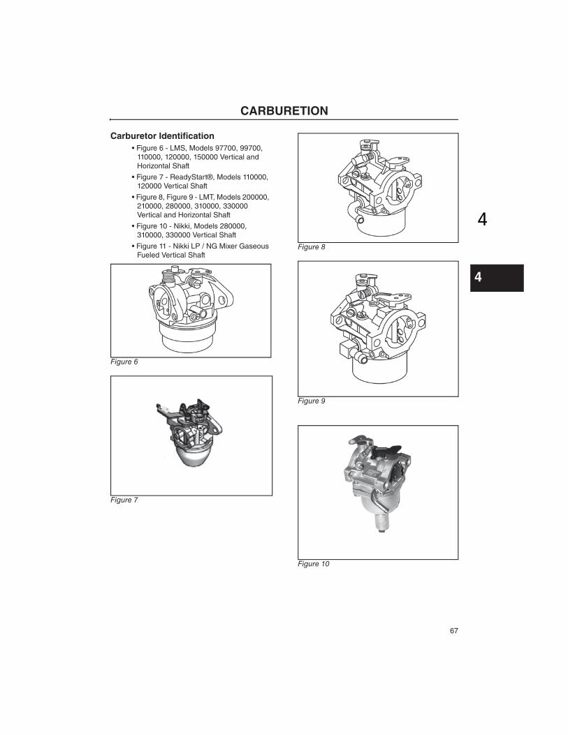
Carburetor Identification
• Figure 6 - LMS, Models 97700, 99700,
110000, 120000, 150000 Vertical and
Horizontal Shaft
• Figure 7 - ReadyStart®, Models 110000,
120000 Vertical Shaft
• Figure 8, Figure 9 - LMT, Models 200000,
210000, 280000, 310000, 330000
Vertical and Horizontal Shaft
• Figure 10 - Nikki, Models 280000,
310000, 330000 Vertical Shaft
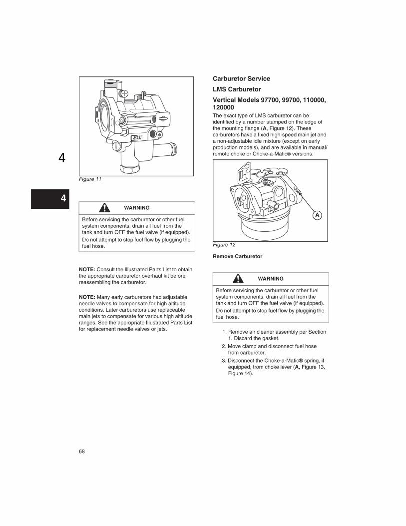
• Figure 11 - Nikki LP / NG Mixer Gaseous
Fueled Vertical Shaft
Figure 6
Figure 7
Figure 8
Figure 9
Figure 10
68
44
Figure 11
NOTE: Consult the Illustrated Parts List to obtain
the appropriate carburetor overhaul kit before
reassembling the carburetor.
NOTE: Many early carburetors had adjustable
needle valves to compensate for high altitude
conditions. Later carburetors use replaceable
main jets to compensate for various high altitude
ranges. See the appropriate Illustrated Parts List
for replacement needle valves or jets.
Carburetor Service
LMS Carburetor
Vertical Models 97700, 99700, 110000, 120000
The exact type of LMS carburetor can be
identified by a number stamped on the edge of
the mounting flange (A, Figure 12). These
carburetors have a fixed high-speed main jet and
a non-adjustable idle mixture (except on early
production models), and are available in manual/
remote choke or Choke-a-Matic® versions.
Figure 12
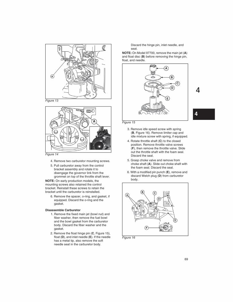
Remove Carburetor
1. Remove air cleaner assembly per Section
1. Discard the gasket.
2. Move clamp and disconnect fuel hose
from carburetor.
3. Disconnect the Choke-a-Matic® spring, if
equipped, from choke lever (A, Figure 13,
Figure 14).
WARNING
Before servicing the carburetor or other fuel
system components, drain all fuel from the
tank and turn OFF the fuel valve (if equipped).
Do not attempt to stop fuel flow by plugging the
fuel hose.
WARNING
Before servicing the carburetor or other fuel
system components, drain all fuel from the
tank and turn OFF the fuel valve (if equipped).
Do not attempt to stop fuel flow by plugging the
fuel hose.
69
44
Figure 13
Figure 14
4. Remove two carburetor mounting screws.
5. Pull carburetor away from the control
bracket assembly and rotate it to
disengage the governor link from the
grommet on top of the throttle shaft lever.
NOTE: On early production models, the
mounting screws also retained the control
bracket. Reinstall these screws to retain the
bracket until the carburetor is reinstalled.
6. Remove the spacer, o-ring, and gasket, if
equipped. Discard the o-ring and the
gasket.
Disassemble Carburetor
1. Remove the fixed main jet (bowl nut) and
fiber washer, then remove the fuel bowl
and the bowl gasket from the carburetor
body. Discard the fiber washer and the
gasket.
2. Remove the float hinge pin (C, Figure 15),
float (D), and inlet needle (E). If the needle
has a metal tip, also remove the soft
needle seat in the carburetor body.
Discard the hinge pin, inlet needle, and
seat.
NOTE: On Model 97700, remove the main jet (A)
and float disc (B) before removing the hinge pin,
float, and needle.
Figure 15
3. Remove idle speed screw with spring
(B, Figure 16). Remove limiter cap and
idle mixture screw with spring, if equipped.
4. Rotate throttle shaft (C) to the closed
position. Remove throttle valve screws
(F), then remove the throttle valve. Slide
out the throttle shaft with the foam seal.
Discard the seal.
5. Grasp choke valve and remove from
choke shaft (A). Slide out choke shaft with
the foam seal. Discard the seal.
6. With a modified pin punch (E), remove and
discard Welch plug (D) from carburetor
body.
Figure 16

70
44
Inspect and Clean Carburetor Components
1. Inspect openings in the carburetor body
for evidence of wear or damage. If found,
replace the entire carburetor assembly.
2. Inspect the choke shaft, choke valve,
throttle shaft, and throttle valve for
evidence of wear or damage. Replace
parts as necessary.
3. Using Carb/Choke Cleaner #100041 or
#100042, thoroughly clean the following
components, then follow with compressed
air to dry:
• Passages in the fixed main jet (bowl nut)
• Inside and outside of the fuel bowl
• Float
• Choke shaft and choke valve
• Throttle shaft and throttle valve
• All passages, openings, and the inside
and outside of the carburetor body
NOTE: Do not soak non-metallic components,
such as floats, o-rings, seals, or diaphragms, in
carb/choke cleaner or they will be damaged.
4. If any passages remain plugged after
cleaning, replace the component or the
entire carburetor assembly.
Assemble Carburetor
Consult the Illustrated Parts List to obtain the
appropriate carburetor overhaul kit before
reassembling the carburetor.
1. Install new Welch plug (A, Figure 17) with
a pin punch (B) of slightly smaller
diameter than the plug. Press against the
plug until it is flat in the carburetor
opening. Do not cave in the plug. Seal the
edge of the plug with a non-hardening
sealant.
Figure 17
2. Install new foam seal (B, Figure 18) on
choke shaft (E), then slide shaft into
carburetor body (C). Rotate shaft
clockwise (A), and insert choke valve into
slot until centered, with dimples (D)
positioned as shown. Actuate the choke
shaft to check for proper movement.
Figure 18
3. Install new foam seal (C, Figure 19) on
throttle shaft (B), then slide shaft into
carburetor body. Rotate shaft until flat is
facing out. Position throttle valve on flat
with numbers facing out (A), then install
screws (D). Actuate the throttle shaft to
check for proper movement.
Figure 19
4. Install idle speed screw and spring. Install
idle mixture screw and spring with a new
limiter cap, if equipped.
5. Using Bushing Driver #19057
(A, Figure 20), install new needle seat with
grooved edge down (B) until firmly seated.
71
44
Figure 20
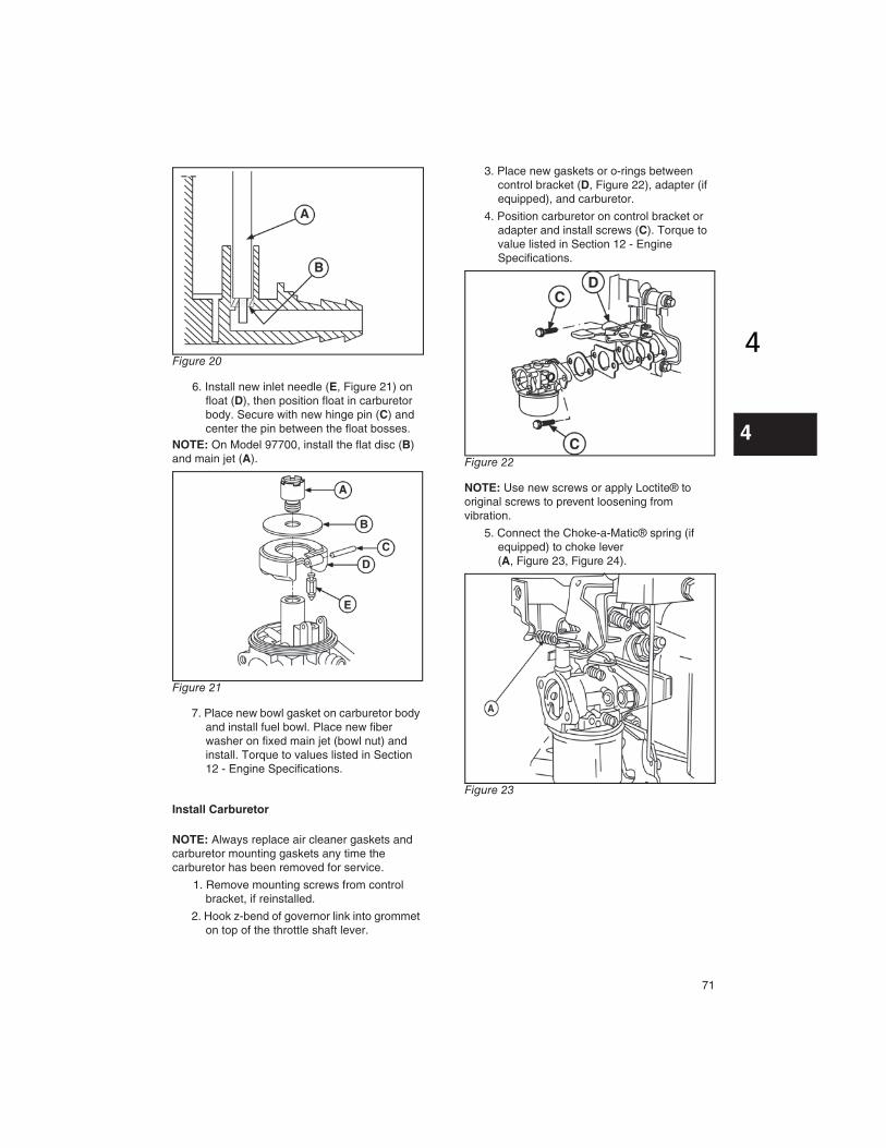
6. Install new inlet needle (E, Figure 21) on
float (D), then position float in carburetor
body. Secure with new hinge pin (C) and
center the pin between the float bosses.
NOTE: On Model 97700, install the flat disc (B)
and main jet (A).
Figure 21
7. Place new bowl gasket on carburetor body
and install fuel bowl. Place new fiber
washer on fixed main jet (bowl nut) and
install. Torque to values listed in Section
12 - Engine Specifications.
Install Carburetor
NOTE: Always replace air cleaner gaskets and
carburetor mounting gaskets any time the
carburetor has been removed for service.
1. Remove mounting screws from control
bracket, if reinstalled.
2. Hook z-bend of governor link into grommet
on top of the throttle shaft lever.
3. Place new gaskets or o-rings between
control bracket (D, Figure 22), adapter (if
equipped), and carburetor.
4. Position carburetor on control bracket or
adapter and install screws (C). Torque to
value listed in Section 12 - Engine
Specifications.
Figure 22
NOTE: Use new screws or apply Loctite® to
original screws to prevent loosening from
vibration.
5. Connect the Choke-a-Matic® spring (if
equipped) to choke lever
(A, Figure 23, Figure 24).
Figure 23

72
44
Figure 24
6. Connect fuel hose to carburetor and
secure with clamp.
7. Using new gasket, install air cleaner
assembly to carburetor per Section 1.
Ensure breather hose is properly installed
on the breather tube.
8. Adjust carburetor, if applicable, per
Section 1.
LMS Carburetor
Horizontal Models 110000, 120000, 150000
The exact type of LMS carburetor can be
identified by a number stamped on the edge of
the mounting flange (A, Figure 25). These
carburetors have a fixed high speed main jet, a
non-adjustable idle mixture (except on early
production models), and manual/remote choke.
Snow engine carburetors utilize both a primer
and a choke for improved starting in cold
temperatures.
Figure 25
Remove Carburetor
1. Remove air cleaner assembly per Section
1. Discard the gasket.
NOTE: Snow engines do not have an air cleaner
assembly. Remove the 1 or 2 piece shroud to
gain access to the carburetor.
2. Move clamp and disconnect fuel hose
from carburetor. Disconnect primer hose,
if equipped.
Figure 26
3. Remove two carburetor mounting screws
or nuts (E, Figure 26).
4. Pull carburetor away from the adapter
assembly (C) and rotate it to disengage
WARNING
Before servicing the carburetor or other fuel
system components, drain all fuel from the
tank and turn OFF the fuel valve (if equipped).
Do not attempt to stop fuel flow by plugging the
fuel hose.
73
44
the governor link from the grommet on top
of the throttle shaft lever (B). Discard
gasket.
Disassemble Carburetor
1. Remove the fixed main jet (bowl nut) and
fiber washer, then remove the fuel bowl
and the bowl gasket from the carburetor
body. Discard the fiber washer and the
gasket.
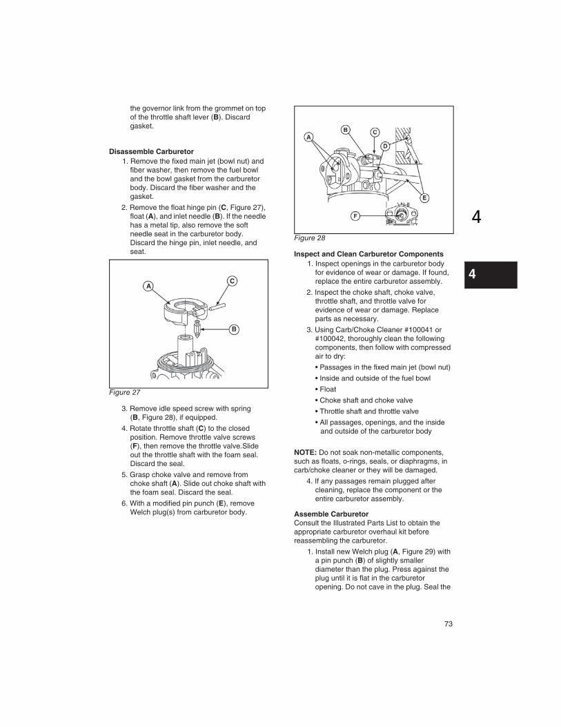
2. Remove the float hinge pin (C, Figure 27),
float (A), and inlet needle (B). If the needle
has a metal tip, also remove the soft
needle seat in the carburetor body.
Discard the hinge pin, inlet needle, and
seat.
Figure 27
3. Remove idle speed screw with spring
(B, Figure 28), if equipped.
4. Rotate throttle shaft (C) to the closed
position. Remove throttle valve screws
(F), then remove the throttle valve.Slide
out the throttle shaft with the foam seal.
Discard the seal.
5. Grasp choke valve and remove from
choke shaft (A). Slide out choke shaft with
the foam seal. Discard the seal.
6. With a modified pin punch (E), remove
Welch plug(s) from carburetor body.
Figure 28
Inspect and Clean Carburetor Components
1. Inspect openings in the carburetor body
for evidence of wear or damage. If found,
replace the entire carburetor assembly.
2. Inspect the choke shaft, choke valve,
throttle shaft, and throttle valve for
evidence of wear or damage. Replace
parts as necessary.
3. Using Carb/Choke Cleaner #100041 or
#100042, thoroughly clean the following
components, then follow with compressed
air to dry:
• Passages in the fixed main jet (bowl nut)
• Inside and outside of the fuel bowl
• Float
• Choke shaft and choke valve
• Throttle shaft and throttle valve
• All passages, openings, and the inside
and outside of the carburetor body
NOTE: Do not soak non-metallic components,
such as floats, o-rings, seals, or diaphragms, in
carb/choke cleaner or they will be damaged.
4. If any passages remain plugged after
cleaning, replace the component or the
entire carburetor assembly.
Assemble Carburetor
Consult the Illustrated Parts List to obtain the
appropriate carburetor overhaul kit before
reassembling the carburetor.
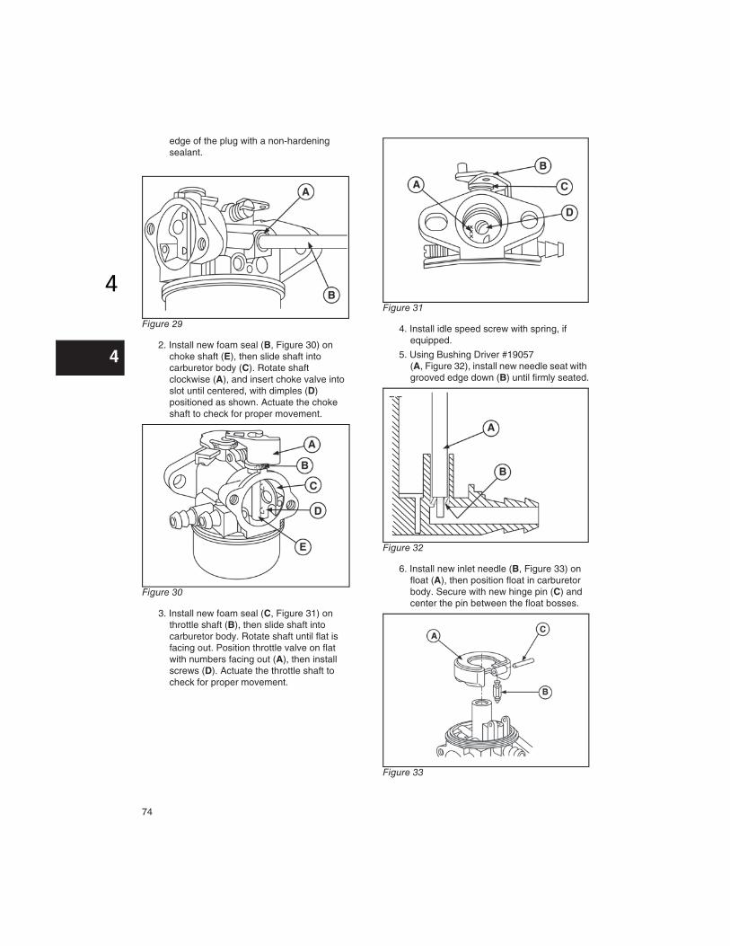
1. Install new Welch plug (A, Figure 29) with
a pin punch (B) of slightly smaller
diameter than the plug. Press against the
plug until it is flat in the carburetor
opening. Do not cave in the plug. Seal the
74
44
edge of the plug with a non-hardening
sealant.
Figure 29
2. Install new foam seal (B, Figure 30) on
choke shaft (E), then slide shaft into
carburetor body (C). Rotate shaft
clockwise (A), and insert choke valve into
slot until centered, with dimples (D)
positioned as shown. Actuate the choke
shaft to check for proper movement.
Figure 30
3. Install new foam seal (C, Figure 31) on
throttle shaft (B), then slide shaft into
carburetor body. Rotate shaft until flat is
facing out. Position throttle valve on flat
with numbers facing out (A), then install
screws (D). Actuate the throttle shaft to
check for proper movement.
Figure 31
4. Install idle speed screw with spring, if
equipped.
5. Using Bushing Driver #19057
(A, Figure 32), install new needle seat with
grooved edge down (B) until firmly seated.
Figure 32
6. Install new inlet needle (B, Figure 33) on
float (A), then position float in carburetor
body. Secure with new hinge pin (C) and
center the pin between the float bosses.
Figure 33

75
44
7. Place new bowl gasket on carburetor body
and install fuel bowl. Place new fiber
washer on fixed main jet (bowl nut) and
install. Torque to values listed in Section
12 - Engine Specifications.
Install Carburetor
NOTE: Always replace air cleaner gaskets and
carburetor mounting gaskets any time the
carburetor has been removed for service.
1. Hook z-bend of governor link into
grommet on top of the throttle shaft lever.
2. Place new gasket (A, Figure 34) between
adapter (B) and carburetor (C).
3. Position carburetor on control bracket and
install screws or nuts (D). Torque to value
listed in Section 12 - Engine
Specifications.
Figure 34
NOTE: Use new screws or apply Loctite® to
original screws to prevent loosening from
vibration.
4. Connect fuel hose to carburetor and
secure with clamp. Connect primer hose, if
equipped.
5. Using new gasket, install air cleaner
assembly to carburetor per Section 1.
Ensure breather hose is properly installed
on the breather tube.
NOTE: For snow engines, install the 1 or 2 piece
shroud.
6. Adjust carburetor, if applicable, per
Section 1.
ReadyStart® Carburetor
Vertical Model 120000
This carburetor utilizes a thermostatically
controlled choke system, requiring no primer or
manual choking when starting. The linkages
installed in the carburetor are not individually
serviceable, requiring replacement with a
complete carburetor assembly.
Remove Carburetor
1. Remove air cleaner assembly per Section
1. Discard the gasket.
2. Move clamp and disconnect fuel hose
from carburetor.
3. Remove two carburetor mounting screws
(A, Figure 35).
Figure 35
4. Carefully remove carburetor from control
bracket. Rotate the carburetor to
disconnect the choke link, spring, and
governor link.
WARNING
Before servicing the carburetor or other fuel
system components, drain all fuel from the
tank and turn OFF the fuel valve (if equipped).
Do not attempt to stop the fuel flow by plugging
the fuel hose.

76
44
5. Remove gasket (A, Figure 36), spacer,
and o-ring between control bracket and
carburetor (B).
Figure 36
Disassemble Carburetor
1. Remove the fixed main jet (bowl nut)
(A, Figure 37) and fiber washer (B), then
remove the fuel bowl (C) and the bowl
gasket (D) from the carburetor body.
Discard the fiber washer and the gasket.
2. Remove the float hinge pin (E), float (F),
and inlet needle (G). Discard the hinge
pin, and inlet needle.
Figure 37
NOTE: Do not disassemble the carburetor body
or linkages.
Inspect and Clean Carburetor
1. Inspect openings in the carburetor body
for evidence of wear or damage. If found,
replace the entire carburetor assembly.
2. Inspect the choke shaft, choke valve,
throttle shaft, and throttle valve for
evidence of wear or damage. If found,
replace the entire carburetor assembly.
3. Using Carb/Choke Cleaner #100041 or
#100042, clean inside and outside
surfaces of carburetor, then follow with
compressed air to dry.
NOTE: Do not soak the carburetor in carb/choke
cleaner or it will be damaged.
4. If any passages remain plugged after
cleaning, replace the entire carburetor
assembly.
Assemble Carburetor
Consult the Illustrated Parts List to obtain the
appropriate carburetor overhaul kit before
reassembling the carburetor.
NOTE: Always replace air cleaner gaskets and
carburetor mounting gaskets any time the
carburetor has been removed for service.
1. Install new hinge pin (E, Figure 38), float
(F), and new inlet needle (G).
2. Install new bowl gasket (D) with the fuel
bowl (C). Replace the fiber washer (B)
and install the fixed main jet (A).
Figure 38

77
44
3. Place new gasket (A, Figure 39), spacer,
and new o-ring between control bracket
(B) and carburetor (C).
4. Position carburetor on control bracket and
install screws. Torque to value listed in
Section 12 - Engine Specifications.
NOTE: Use new screws or apply Loctite® to
original screws to prevent loosening from
vibration.
Figure 39
5. Connect fuel hose to carburetor and
secure with clamp.
6. Using new gasket, install air cleaner
assembly to carburetor per Section 1.
Adjust carburetor, if applicable, per
Section 1.
LMT Carburetor
Horizontal and Vertical Models 200000, 210000, 280000, 310000, 330000
Two versions of this carburetor have been used
(Figures 40 and 41).
These carburetors have a fixed high speed main
jet with a screw for idle mixture and idle speed
adjustment. The letters LMT are cast into the
body of the carburetor while the identification
numbers are stamped into the carburetor
mounting flange next to the idle mixture screw or
above the fuel inlet.
Figure 40
Figure 41
WARNING
Before servicing the carburetor or other fuel
system components, drain all fuel from the
tank and turn OFF the fuel valve (if equipped).
Do not attempt to stop the fuel flow by plugging
the fuel hose.

78
44
Remove Carburetor
1. Disconnect wire(s) from the carburetor
solenoid. Two styles of solenoids have
been used (Figure 42).
Figure 42
2. Remove air cleaner assembly per
Section 1. Discard the gasket.
3. Move clamp and disconnect hose from
carburetor.
4. Remove two carburetor screws or nuts
while holding carburetor.
5. Carefully rotate carburetor to disconnect
throttle (A, Figure 43) and spring (B) and
the choke link during removal.
Figure 43
Disassemble Carburetor
1. Remove solenoid and solenoid washer.
Discard washer. Remove float bowl and
float bowl gasket from carburetor. Discard
gasket.
2. Using Carburetor Nozzle Screwdriver
#19280, remove the main carburetor
emulsion tube (A, Figure 44).
Figure 44
3. Remove float hinge pin, float, and inlet
needle. Discard the hinge pin and inlet
needle.
4. Screw a 1/4-20 tap into fuel inlet seat 3-4
turns and remove.
5. Place a hex nut (A, Figure 45) and washer
(B) on a 1/4-20 screw.
Place 1/4” drive 3/8” socket (C) over fuel
inlet seat.
6. Thread screw into tapped inlet seat until
screw bottoms. Thread nut down to
washer and continue turning nut until inlet
seat is free from carburetor body.
Figure 45
7. Remove idle mixture limiter cap, when
used, then remove idle mixture screw with
spring and idle speed screw with spring.
8. Rotate throttle shaft to closed position and
remove throttle valve screws and throttle
valve.
9. Remove throttle shaft, foam seal, and
throttle shaft seal from carburetor body.
Discard seals.
10. If carburetor is equipped with a plastic
choke shaft, rotate choke shaft to wide

79
44
open position, then pull choke valve out of
choke shaft. Remove choke shaft, return
spring (when used), and foam seal.
Discard seal.
- OR -
If carburetor is equipped with a metal choke
shaft, rotate choke shaft to closed position.
Remove two choke valve screws and choke
valve. Remove choke shaft, return spring and
foam seal. Discard seal.
11. With a modified pin punch (A, Figure 46)
remove welch plug (B) from carburetor
body.
Figure 46
NOTE: Do not attempt to remove the pilot jets,
which are pressed in and not serviceable.
Inspect and Clean Carburetor
1. Inspect openings in the carburetor body
for evidence of wear or damage. If found,
replace the entire carburetor assembly.
2. Inspect the choke shaft, choke valve,
throttle shaft, and throttle valve for
evidence of wear or damage. Replace
parts as necessary.
3. Using Carb/Choke Cleaner #100041 or
#100042, thoroughly clean the following
components, then follow with compressed
air to dry:
• Passages in the fixed main jet (bowl nut)
or emulsion tube
• Inside and outside of the fuel bowl
• Float
• Choke shaft and choke valve
• Throttle shaft and throttle valve
• All passages, openings, and the inside
and outside of the carburetor body
NOTE: Do not soak non-metallic components,
such as floats, o-rings, seals, or diaphragms, in
carb/choke cleaner or they will be damaged.
4. If any passages remain plugged after
cleaning, replace the component or the
entire carburetor assembly.
Assemble Carburetor
Consult the Illustrated Parts List to obtain the
appropriate carburetor overhaul kit before
reassembling the carburetor.
1. Install new welch plug (A, Figure 47) with
pin punch (B) of slightly smaller diameter
than the plug. Press against the plug until
it is flat in the carburetor opening. Do not
cave in plug. Seal the edge of the plug
with non-hardening sealant.
Figure 47
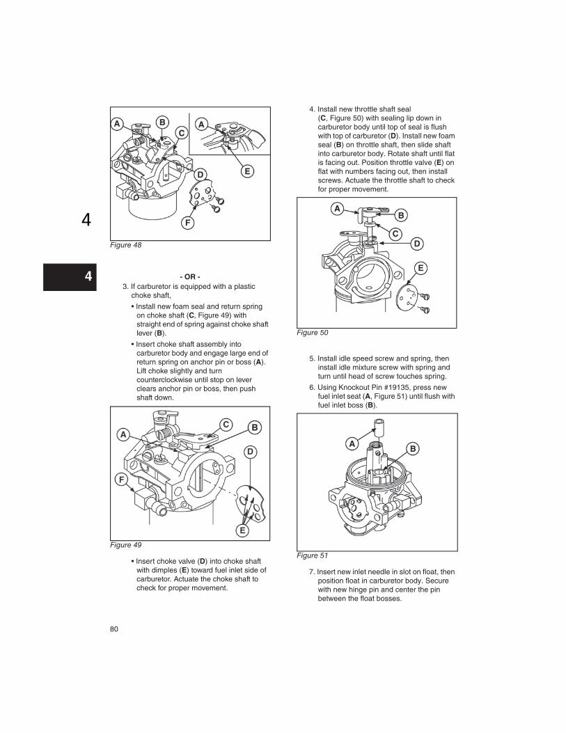
2. If carburetor is equipped with a metal
choke shaft,
• Install new foam seal and return spring
(C, Figure 48) on choke shaft, hooking
small hook (A) in notch on choke lever
(D).
• Insert choke shaft assembly into
carburetor body and engage large end of
return spring (E) on boss. If carburetor
has detent spring, guide spring into slot
in choke shaft lever (B).
• Place choke valve (F) on shaft and install
screws, then actuate the choke shaft to
check for proper movement.
80
44
Figure 48
- OR -
3. If carburetor is equipped with a plastic
choke shaft,
• Install new foam seal and return spring
on choke shaft (C, Figure 49) with
straight end of spring against choke shaft
lever (B).
• Insert choke shaft assembly into
carburetor body and engage large end of
return spring on anchor pin or boss (A).
Lift choke slightly and turn
counterclockwise until stop on lever
clears anchor pin or boss, then push
shaft down.
Figure 49
• Insert choke valve (D) into choke shaft
with dimples (E) toward fuel inlet side of
carburetor. Actuate the choke shaft to
check for proper movement.
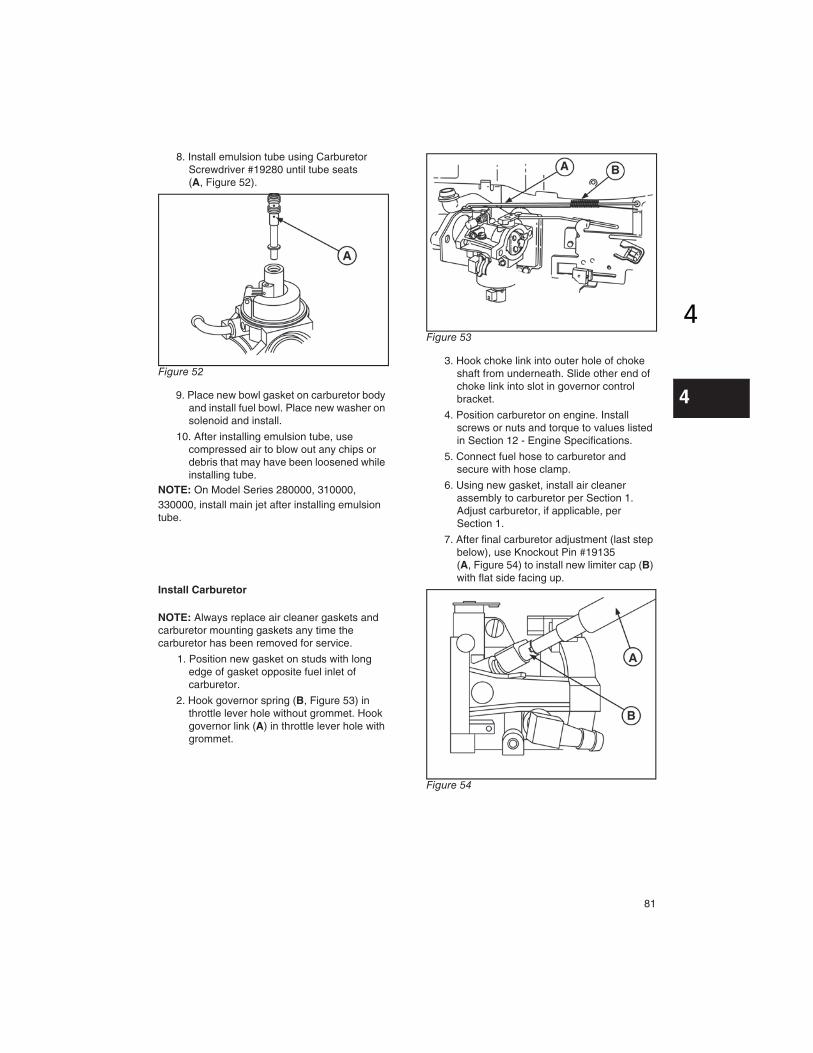
4. Install new throttle shaft seal
(C, Figure 50) with sealing lip down in
carburetor body until top of seal is flush
with top of carburetor (D). Install new foam
seal (B) on throttle shaft, then slide shaft
into carburetor body. Rotate shaft until flat
is facing out. Position throttle valve (E) on
flat with numbers facing out, then install
screws. Actuate the throttle shaft to check
for proper movement.
Figure 50
5. Install idle speed screw and spring, then
install idle mixture screw with spring and
turn until head of screw touches spring.
6. Using Knockout Pin #19135, press new
fuel inlet seat (A, Figure 51) until flush with
fuel inlet boss (B).
Figure 51
7. Insert new inlet needle in slot on float, then
position float in carburetor body. Secure
with new hinge pin and center the pin
between the float bosses.
81
44
8. Install emulsion tube using Carburetor
Screwdriver #19280 until tube seats
(A, Figure 52).
Figure 52
9. Place new bowl gasket on carburetor body
and install fuel bowl. Place new washer on
solenoid and install.
10. After installing emulsion tube, use
compressed air to blow out any chips or
debris that may have been loosened while
installing tube.
NOTE: On Model Series 280000, 310000,
330000, install main jet after installing emulsion
tube.
Install Carburetor
NOTE: Always replace air cleaner gaskets and
carburetor mounting gaskets any time the
carburetor has been removed for service.
1. Position new gasket on studs with long
edge of gasket opposite fuel inlet of
carburetor.
2. Hook governor spring (B, Figure 53) in
throttle lever hole without grommet. Hook
governor link (A) in throttle lever hole with
grommet.
Figure 53
3. Hook choke link into outer hole of choke
shaft from underneath. Slide other end of
choke link into slot in governor control
bracket.
4. Position carburetor on engine. Install
screws or nuts and torque to values listed
in Section 12 - Engine Specifications.
5. Connect fuel hose to carburetor and
secure with hose clamp.
6. Using new gasket, install air cleaner
assembly to carburetor per Section 1.
Adjust carburetor, if applicable, per
Section 1.
7. After final carburetor adjustment (last step
below), use Knockout Pin #19135
(A, Figure 54) to install new limiter cap (B)
with flat side facing up.
Figure 54
82
44
Nikki Carburetor
Vertical Models 280000, 310000, 330000
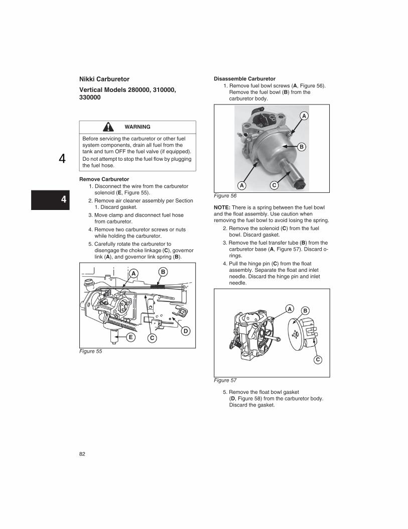
Remove Carburetor
1. Disconnect the wire from the carburetor
solenoid (E, Figure 55).
2. Remove air cleaner assembly per Section
1. Discard gasket.
3. Move clamp and disconnect fuel hose
from carburetor.
4. Remove two carburetor screws or nuts
while holding the carburetor.
5. Carefully rotate the carburetor to
disengage the choke linkage (C), governor
link (A), and governor link spring (B).
Figure 55
Disassemble Carburetor
1. Remove fuel bowl screws (A, Figure 56).
Remove the fuel bowl (B) from the
carburetor body.
Figure 56
NOTE: There is a spring between the fuel bowl
and the float assembly. Use caution when
removing the fuel bowl to avoid losing the spring.
2. Remove the solenoid (C) from the fuel
bowl. Discard gasket.
3. Remove the fuel transfer tube (B) from the
carburetor base (A, Figure 57). Discard o-
rings.
4. Pull the hinge pin (C) from the float
assembly. Separate the float and inlet
needle. Discard the hinge pin and inlet
needle.
Figure 57
5. Remove the float bowl gasket
(D, Figure 58) from the carburetor body.
Discard the gasket.
WARNING
Before servicing the carburetor or other fuel
system components, drain all fuel from the
tank and turn OFF the fuel valve (if equipped).
Do not attempt to stop the fuel flow by plugging
the fuel hose.

83
44
Figure 58
6. If equipped, remove the idle mixture screw
with spring (A, Figure 59) and the idle
speed screw with spring (B).
Figure 59
7. Rotate the throttle shaft to the closed
position (Figure 60). Remove two screws
(A) and the throttle plate.
Figure 60
8. Pull the throttle shaft from the carburetor
body. Discard foam seals.
9. Rotate the choke shaft to the wide open
position (Figure 61), then pull the choke
plate (B) from the shaft (A).
Figure 61
10. Remove the choke shaft, return spring,
and foam seal. Discard spring and seal.
11. Remove the main jet and seal.
NOTE: Do not attempt to remove the pilot jets,
which are pressed in and not serviceable.
12. Remove the welch plug (A, Figure 62)
from the carburetor with a modified pin
punch. Discard the welch plug.
Figure 62
Inspect and Clean Carburetor
1. Inspect openings in the carburetor body
for evidence of wear or damage. If found,
replace the entire carburetor assembly.
2. Inspect the choke shaft, choke valve,
throttle shaft, and throttle valve for
evidence of wear or damage. Replace
parts as necessary.
3. Using Carb/Choke Cleaner #100041 or
#100042, thoroughly clean the following
components, then follow with compressed
air to dry:
• Passages in the fuel transfer tube and
jets
• Inside and outside of the fuel bowl
• Float

84
44
• Choke shaft and choke valve
• Throttle shaft and throttle valve
• All passages, openings, and the inside
and outside of the carburetor body
NOTE: Do not soak non-metallic components,
such as floats, o-rings, seals, or diaphragms, in
carb/choke cleaner or they will be damaged.
4. If any passages remain plugged after
cleaning, replace the component or the
entire carburetor assembly.
Assemble Carburetor
1. Install new welch plug with pin punch of
slightly smaller diameter than the plug.
Press against the plug until it is flat in the
carburetor opening. Do not cave in the
plug. Seal the edge of the plug with a non-
hardening sealant.
2. Reinstall main jet and seal
3. Install new seal and spring on the choke
shaft with the top of the spring contacting
the choke shaft lever (B, Figure 63).
Figure 63
4. Turn the choke shaft counterclockwise
while gently pushing it into the carburetor
body until the bottom end of the spring (D)
rests on the back of the spring perch (A).
5. Lift the choke shaft up slightly and
continue turning counterclockwise until the
stop on the lever clears the spring perch.
Push the shaft inward. When released, the
choke shaft lever should rest on the spring
perch as shown (Figure 64).
Figure 64
6. Insert the choke plate into the choke shaft
with the dimples toward the fuel inlet side
of the carburetor. Dimples center the
choke plate on the shaft (A, Figure 65).
Figure 65
7. Install foam washer (B) to throttle shaft
(A, Figure 66). Install throttle shaft to the
carburetor body. Turn throttle shaft until
flat is facing out.
8. Lay the throttle plate (C) on the flat of the
shaft. Install two screws (D).
Figure 66

85
44
NOTE: The holes in the throttle plate are offset. If
the throttle plate is installed incorrectly, if will not
close.
9. If equipped, install idle mixture screw with
spring and the idle speed screw with
spring. Turn each screw until the head of
the screw touches the spring.
10. Insert new inlet needle (B) into the slot on
the float (A, Figure 67).
11. Place the needle and float assembly into
the fuel transfer tube. Secure with new
hinge pin (C) and center the pin between
the float bosses.
Figure 67
12. Install new o-ring on fuel transfer tube (E).
13. Place new float bowl gasket (A, Figure 68)
on the carburetor body, then press the
fuel transfer tube (B, Figure 69) onto the
carburetor base (C).
Figure 68
Figure 69
NOTE: The locating tang on the fuel transfer
tube MUST be placed in the recess of the
carburetor base as shown.
14. Insert the spring (A, Figure 70) to the
bottom of the float assembly. Place the
fuel bowl on the carburetor base, and
fasten with screws. Torque screws per
values listed in Section 12 - Engine
Specifications.
Figure 70
15. Install solenoid with new gasket. Torque
solenoid to values listed in Section 12 -
Engine Specifications.
Install Carburetor
1. Place new gasket between carburetor and
manifold with long edge of gasket
opposite the fuel inlet.
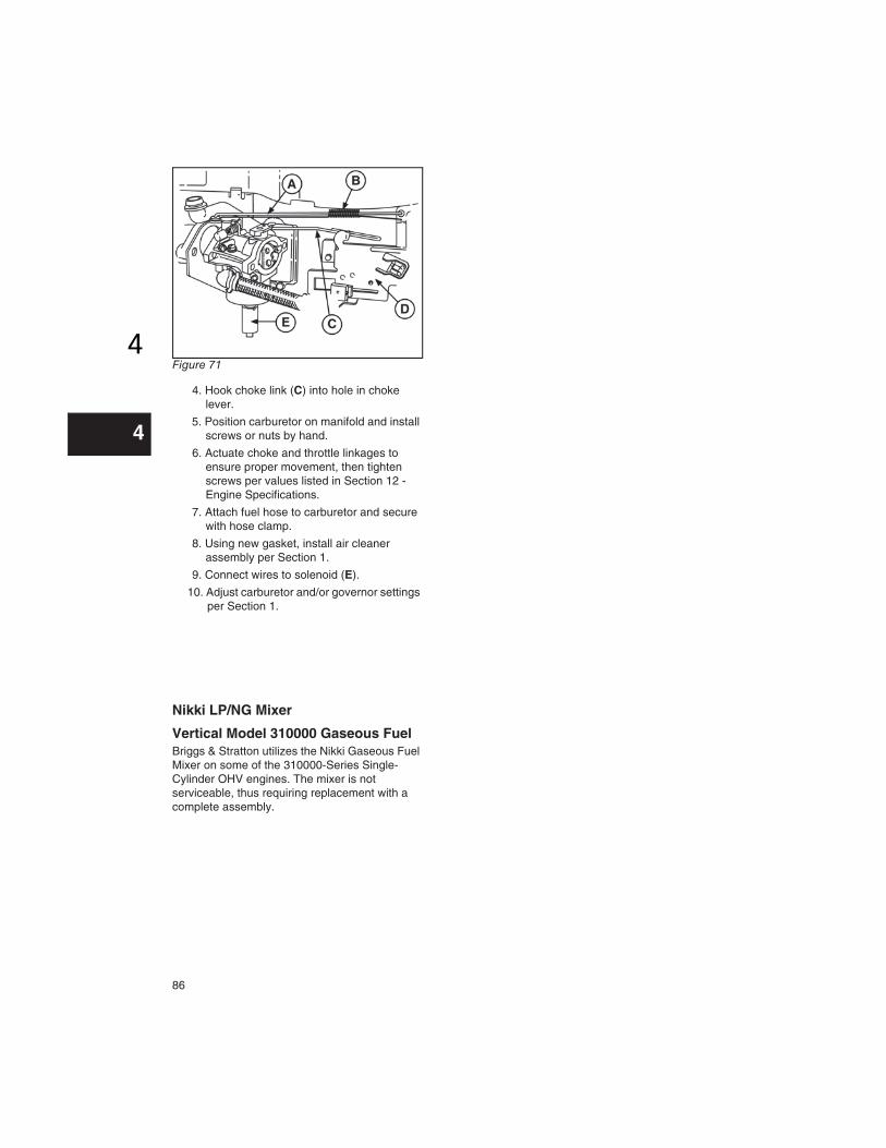
2. Hook governor link spring (B, Figure 71) in
non-grommet throttle lever hole.
3. Hook governor link (A) in grommet throttle
lever hole. Link fits over top of lever.
86
44
Figure 71
4. Hook choke link (C) into hole in choke
lever.
5. Position carburetor on manifold and install
screws or nuts by hand.
6. Actuate choke and throttle linkages to
ensure proper movement, then tighten
screws per values listed in Section 12 -
Engine Specifications.
7. Attach fuel hose to carburetor and secure
with hose clamp.
8. Using new gasket, install air cleaner
assembly per Section 1.
9. Connect wires to solenoid (E).
10. Adjust carburetor and/or governor settings
per Section 1.
Nikki LP/NG Mixer
Vertical Model 310000 Gaseous Fuel
Briggs & Stratton utilizes the Nikki Gaseous Fuel
Mixer on some of the 310000-Series Single-
Cylinder OHV engines. The mixer is not
serviceable, thus requiring replacement with a
complete assembly.