Fire Extinguisher by Cease Fire & Electrical Services Mumbai
Electrical Design Guidelines
Version 3 Page 1 of 48
SECTION 25
ELECTRICAL SERVICES INCLUDING FIRE AND SECURITY SERVICES
Table of Contents 25.0 ELECTRICAL SERVICES ........................................................................................................ 4
25.1 INTENT OF THE JAMES COOK UNVERSITY DESIGN GUIDELINES ................................................. 4
25.2 COMPLIANCE AND APPROVALS .................................................................................................. 4
25.2.1 Compliance Requirements .......................................................................................... 4
25.2.2 Non-Conformance Approvals ...................................................................................... 4
25.2.3 Design Approvals ......................................................................................................... 5
25.2.4 NCC Version to Apply .................................................................................................. 5
25.2.5 Site Infrastructure Connection Approvals ................................................................... 5
25.3 DESIGN PROCESS REQUIREMENTS .............................................................................................. 6
25.3.1 Roles and Responsibilities ........................................................................................... 6
25.3.2 Interfaces with Other Disciplines ................................................................................ 6
25.3.3 Schematic Design (SD) Report / Design Review .......................................................... 6
25.3.4 Developed Design (DD) Report / Design Review ........................................................ 7
25.3.5 Construction Contract Documents Requirements .................................................... 10
25.3.6 Handover Requirements ........................................................................................... 11
25.4 ELECTRICAL SERVICES DESIGN AND EQUIPMENT REQUIREMENTS .......................................... 13
25.4.1 Design for project and future .................................................................................... 13
25.4.2 Design for Tropical Areas .......................................................................................... 14
25.4.3 Environmentally Sustainable Design ......................................................................... 14
25.4.4 Design for Cyclone Prone Areas ................................................................................ 15
25.4.5 Corrosion Prevention and Protection ....................................................................... 15
25.4.6 Disruption of Power .................................................................................................. 16
25.4.7 Independent Testing ................................................................................................. 16
25.4.8 Equipment Quality and Support ............................................................................... 16
25.4.9 Design for Maintenance ............................................................................................ 16
25.4.10 AQIS / OGTR / Authorities ......................................................................................... 16
25.4.11 Arrangement of Services ........................................................................................... 16
25.4.12 Locating Existing Services .......................................................................................... 17
25.4.13 Services Trench ......................................................................................................... 17
25.4.14 Safety in Design ......................................................................................................... 17
25.4.15 Solar Power ............................................................................................................... 18
25.4.16 Reuse of Existing Services or Equipment .................................................................. 18
Electrical Design Guidelines
Version 3 Page 2 of 48
25.4.17 Redundant Services ................................................................................................... 18
25.4.18 Refurbishment of Existing Buildings ......................................................................... 18
25.4.19 Identification of Equipment / Services ...................................................................... 18
25.5 HIGH VOLTAGE ELECTRICAL SERVICES ...................................................................................... 19
25.5.1 HV Interfaces with Existing Infrastructure ................................................................ 19
25.5.2 HV Protection Study – RMU’s and Transformers ...................................................... 20
25.5.3 Ring Main Units and Transformers (Substation) ....................................................... 21
25.5.4 Underground HV Electrical Services ......................................................................... 21
25.5.5 HV Earthing and Global Earth Connection ................................................................ 22
25.5.6 HV Switchgear ........................................................................................................... 22
25.5.7 HV Cables .................................................................................................................. 24
25.5.8 HV Motors and other HV Equipment (Loads) ........................................................... 24
25.6 LOW VOLTAGE ELECTRICAL SERVICES ....................................................................................... 25
25.6.1 Maximum demand calculations ................................................................................ 25
25.6.2 LV Supply ................................................................................................................... 25
25.6.3 Main Switchboard ..................................................................................................... 25
25.6.4 Distribution Boards ................................................................................................... 26
25.6.5 Surge Diverters .......................................................................................................... 27
25.6.6 Switchgear ................................................................................................................. 27
25.6.7 Electrical Riser Cupboard .......................................................................................... 28
25.6.8 Cable Supports .......................................................................................................... 28
25.6.9 Underground LV Electrical Services .......................................................................... 28
25.6.10 Motors and VSDs ....................................................................................................... 29
25.6.11 Wiring ........................................................................................................................ 29
25.6.12 Generator Supply ...................................................................................................... 30
25.6.13 Uninterruptable Power Supply (UPS) ........................................................................ 32
25.6.14 Power Factor Correction ........................................................................................... 32
25.6.15 Lightning and Surge Protection ................................................................................. 32
25.6.16 Small Power .............................................................................................................. 33
25.6.17 Emergency Lighting ................................................................................................... 33
25.6.18 Lighting ...................................................................................................................... 34
25.6.19 Lighting Controls - Generally ..................................................................................... 37
25.6.20 Lecture Theatre Lighting ........................................................................................... 38
25.6.21 Laboratories – Specific Occupancy Requirements .................................................... 41
25.7 ELECTRONIC FIRE SERVICES – DRY FIRE .................................................................................... 42
25.8 ELECTRONIC SECURITY SERVICES .............................................................................................. 43
25.9 EMS – ENERGY MONITORING SYSTEM ..................................................................................... 45
25.10 USEFUL INFORMATION ......................................................................................................... 46

Electrical Design Guidelines
Version 3 Page 3 of 48
25.10.1 National and State Legislation / Standards / Codes.................................................. 46
25.10.2 Discipline Specific Standards ..................................................................................... 46
25.10.3 Interfaces .................................................................................................................. 47
Version Date Authors Summary of Changes
1 10 April 2013 Multitech for JCU First Edition
2 30 September 2013
Manager, Infrastructure Services
Revised with JCU comments
3 30 October 2013
Manager, Infrastructure Services
Metering information updated to reflect legislation requirements

Electrical Design Guidelines
Version 3 Page 4 of 48
25.0 ELECTRICAL SERVICES
25.1 INTENT OF THE JAMES COOK UNVERSITY DESIGN GUIDELINES
James Cook University was established to pursue and encourage study and research, especially in subjects of importance to the people of the tropics. James Cook University is Queensland’s second oldest university and through its research, graduates and industry links, is a major driver of economic growth and social change in northern Queensland.
Staff and students of JCU use its unique locations to conduct nationally significant and internationally-recognised research in areas such as marine sciences, biodiversity, tropical ecology and environments, global warming, tourism and in tropical medicine and public health care in underserved populations. Its network of specialist centres, institutes and research stations span a wide geographic area from marine islands to the outback and the students come from many backgrounds, promoting a rich cultural and experiential diversity on campus.
These design guidelines are the minimum acceptable standard and have been developed to ensure that projects delivered by JCU comply with the University’s vision, are appropriate for the unique tropical environments and incorporate the lessons learnt from previous projects. The Deputy Director – Planning and Development is responsible to ensure these Design Guidelines achieve the best design outcomes for JCU.
25.2 COMPLIANCE AND APPROVALS
25.2.1 Compliance Requirements
All design and works are to comply with the latest versions of all Australian National, Queensland State, legislation and standards, as well as local council/authority requirements. Further details are provided in Section 25.10.
All other sections of these Guidelines are to be read for completeness as this document has been developed as a section of a suite of documents.
Where there is a discrepancy between requirements, legislation and regulation to take precedent over these Guidelines.
25.2.2 Non-Conformance Approvals
All project team members (for example Consultants, D&C Contractors, Principal Consultants, Internal/External project managers, subcontractors etc.) are responsible for delivering the project in accordance with the project brief, these guidelines, user group information and other contractual documents.
Where there are sound engineering reasons to deviate from these documents, a written non-conformance request is to be submitted to the Deputy Director – Planning and Development via the JCU Project Manager.
This could apply when the project involve aspects, scope, technologies, locations or other applications that are not specifically briefed or covered by the Design Guidelines, the non-conformance request will include clear information on:
Technical Aspect that is not covered
A range of options to address the issue
Time and costs implications for each option
Effect of the aspect on the design and on other trades

Electrical Design Guidelines
Version 3 Page 5 of 48
Effects on users, maintenance, access, life of plant, energy efficiency, cost
Effects on future re-allocation of the space / system etc.
Recommended solution to the issue
A Non-Conformance register is to be maintained by the Consultant and the details of each request plus the outcome are to be recorded.
Before departures in design intent are approved for the successful consulting engineer, detailed energy modelling against the NABERs’ scheme shall be required. Departures shall prove there is an advantage to JCU in terms of energy savings and operating cost savings.
25.2.3 Design Approvals
Irrespective of directions received from JCU, the Consultant remains fully responsible for the design solution developed.
All designs done for and on behalf of JCU require RPEQ certification, unless approved by the Manager, Infrastructure Services.
Form 15 Design Certification and QFRS (if appropriate) is to be obtained.
25.2.4 NCC Version to Apply
Confirm with JCU’s Project Manager which version of the National Construction Code (NCC) that is applicable to the works.
25.2.5 Site Infrastructure Connection Approvals
The Manager, Infrastructure Services shall approve all connections to existing infrastructure, including the HV and LV reticulation.
Specific HV requirements; a single request for approval to connect to the HV network is to be sent to the Manager, Infrastructure Services, at least 10 working days before the connection is required. This document shall contain the following information;
Form 15 or statement from electrical designer that design meets code requirements
Form 16 or statement from electrical installer that installation done in accordance with design
Electrical design criteria issued to electrical designers, especially protection criteria
Details of electrical design, cable sizes, loads, impact on JCU protection settings, etc.
Confirmation of fault levels - and impact on our network
Confirmation that electrical design is within current protection envelope and comments on any expected impact on our reticulation
Electrical commissioning plan and comment on progress to date
HV Auditors report with all supporting documentation
Names of persons visually inspecting cable connections at Transformers and GMS, confirming methodology, labelling, locking, earthing.
Report from electrical consultant, photos taken, Earth mat readings with witness signatures and dates of tests, Earth mat design and construction details, confirming CADWeld connections below ground and CADWeld or C Crimp connections above ground, as agreed with the Manager, Infrastructure Services.
Witnessed (signed and name and position and company represented) impedance values to earth and then same for global earth connection to main bar
Updated HV Schematic for approval

Electrical Design Guidelines
Version 3 Page 6 of 48
Schematic of final LV connection including expected maximum load
25.3 DESIGN PROCESS REQUIREMENTS
25.3.1 Roles and Responsibilities
JCU does not wish to be separated from the design process, regardless of whether the project is traditionally delivered, delivered through Managing Contractor, D&C contractor or other.
25.3.1.1 Traditional Delivery
Where traditional delivery is chosen, the framework may be through a Principal Consultant (such as an Architect or Project Manager), or direct to JCU.
The Principal Consultant is to arrange workshops with the JCU Deputy Director – Planning and Development, Manager, Infrastructure Services and Manager, Asset Strategy and Maintenance and other technical staff as directed by these managers from initiation of schematic design.
25.3.1.2 Managing Contractor Framework
Arrange workshops and information issues throughout the design process with the JCU Deputy Director – Planning and Development, Manager, Infrastructure Services, Manager, Asset Strategy and Maintenance and other technical staff as directed by these managers (through the Managing Contractor and JCU’s Project Manager).
25.3.1.3 Communication Arrangements
All communication with JCU is to be via the JCU Project Manager. Minutes of any design review meetings etc. are to be provided to all participants via the JCU Project Manager.
25.3.2 Interfaces with Other Disciplines
Ensure that all works necessary for the complete installation and successful operation are advised to other consultants and specified as interface with other engineering disciplines, professions or specialists.
Ensure that information required to accurately design the services is obtained from other consultants as required. Additional information is available in section 25.10.3.
25.3.3 Schematic Design (SD) Report / Design Review
The Schematic Design (SD) report will give a high level understanding to University of the requirements for the project.
25.3.3.1 Report Content
The drawing numbers and revisions the SD report is based upon e.g. Architectural, As Installed drawings etc.
A detailed list of the electrical scope of works for the project
A detailed list of the applicable standards, regulations and local authority requirements that the project will conform to
Where existing plant is being utilised, whether this plant is being used, replaced, refurbished etc. with indication of associated issues and costs.
A high level description of the method of servicing the various spaces in the project
BCA/NCC Light Calculations Sheet
Preliminary Findings from the Building Energy Model
Outcomes and recommendations from Safety in Design workshop(s)
Electrical Design Guidelines
Version 3 Page 7 of 48
List of Ecological Sustainable Development (ESD) opportunities
Non-Conformance Register listing any deviations from Legislation, Standards, Codes, Guidelines or Project Brief.
List of Assumptions, Boundaries (battery limits or tie-in points) and Specific Exclusions
Equipment List with estimated sizes/specifications
Concept cable and motor schedules
Proposed cable and equipment numbering system
Estimated services consumptions (maximum demand, etc.)
Proposed Drawing Register and Deliverables List
Layout drawings showing any interfaces with existing services and structures, including proposed services corridor/trenches.
Investment Decision Report including Cost (Capex and Opex) and Schedule estimates, Lifecycle costs and indicating any areas of risk to the project delivery. This document to be resubmitted based on feedback from the SD review and approved by the JCU Deputy Director – Planning and Development prior to commencement of Detailed Design.
Where option analysis was included, a recommendation on the option to take forward with supporting information/decision criteria.
Outcomes and recommendations for safety in design, and design risk assessment workshops particularly responding to (or addressing) design elements.
List of proposed design development activities/milestone schedule and deliverables
25.3.3.2 Submission Format
This information is to be submitted to the JCU Project Manager as an A4 colour PDF file with A3 drawing attachments, in hard and electronic format. The Consultant may be requested to deliver a presentation (in person or via VC) to JCU stakeholders and decision makers.
25.3.3.3 Design Review
Submit SD drawings / report and non-conformance register to JCU’s Project Manager in full size hard copies (1) and on CD for a full design review in accordance with the project schedule, allow a minimum of 2 weeks for design review.
Inform the JCU’s Project Manager as soon as possible if the drawings are going to be delayed for any reason.
Following receipt of the design review comments from JCU, respond formally with
Acknowledgement that changes will be actioned, and
List any areas where the design review comments require additional discussion and proposed manner of resolution.
25.3.4 Developed Design (DD) Report / Design Review
The DD report will provide more detail on the design for the accepted option and design approaches.
25.3.4.1 Report Content
Full return brief for the electrical services
The drawing numbers and revisions the DD report is based upon e.g. Architectural, As Installed drawings etc.
Provide detailed information of all existing site services, their re-use, refurbishment, relocation or removal

Electrical Design Guidelines
Version 3 Page 8 of 48
Project specific building energy study derived from the Building Energy Model
BCA/NCC Light Calculations Sheet
Detail on maximum demand calculations including design calculations for all cables and equipment to verify sizing and showing design allowances and safety margin used
Detail on switchboard sizes and location
Detail on design approach for each type of system / area etc.
In each case options investigated, reasons or supporting information for design choices,
Detail on loads and consumptions to existing services, including preliminary assessment of effect on existing HV network including fault level and protection settings LV fault level, switchboard fault ratings and protection settings.
Statement on how the existing services will be impacted by these additional loads and any specify any required upgrades
Preliminary indication of changes to HV switching protocols
Preliminary lighting and power design
Preliminary single line diagrams
Details of all connection points to existing site HV, LV, Telecommunications, Fire and Security Services etc.
Details – Plans and Elevations of all in-building/cast in structure/concealed services layouts including floor plans
Life cycle costing on major equipment
Detail on special measures for spaces with additional requirements (e.g. PC2, PC3, laboratories etc.)
ESD Opportunities Register
Updated Non-Conformance Register listing any deviations from codes, standards, legislation, guidelines or project brief.
Updated Assumptions, Boundaries (battery limits or tie-in points) and Specific Exclusions
Final Equipment List with sizes/specifications
Drawing Register and Deliverables list
All IFC drawings and design calculations
Finalised recommendations for preventative maintenance and list of critical spares on proposed equipment
Risk Matrix for design methodology (i.e. single points of failure)
Areas of risk to the project during construction and commissioning
List of construction activities/milestone schedule and deliverables, including construction and commissioning hold point/inspection/witness/approvals.
25.3.4.2 Submission Format
This information is to be submitted to the JCU Project Manager as an A4 colour PDF file with A3 drawing attachments, in hard and electronic format. The Consultant may be requested to deliver a presentation (in person or via VC) to JCU stakeholders and decision makers.
25.3.4.3 Supporting Documentation
Details on connections to all infrastructure
Calculations supporting cable and equipment sizing
Maximum 1:500 existing site services drawings
Maximum 1:500 proposed site services drawings
Maximum 1:100 electrical services Floor Plans.

Electrical Design Guidelines
Version 3 Page 9 of 48
Revised HV schematics and single line diagrams
25.3.4.4 Design Review
Submit DD drawings / report and non-conformance register to JCU’s Project Manager in full size hard copies (1) and on CD for a full design review in accordance with the project schedule, allow a minimum of 2 weeks for design review.
Inform the JCU’s Project Manager as soon as possible if the drawings are going to be delayed for any reason.
Following receipt of the design review comments from JCU, respond formally with
Acknowledgement that changes will be actioned, and
List any areas where the design review comments require additional discussion and proposed manner of resolution.
25.3.4.5 Developed Design JCU RPEQ Certification Schedule
This table shall be completed by the DD Design Engineer as below, or as modified by the Manager, Infrastructure Services, and submitted for confirmation.

Electrical Design Guidelines
Version 3 Page 10 of 48
Project
Project Number
Date
Company
RPEQ Design Engineer
RPEQ Licence Number
Building Area sqm
Calculated Maximum Demand kW
Transformer Size kVA
Length of HV cable kW
Transformer Size kVA
Electrical Services Estimated Capital Investment $
Total number of Transformers No. Off
Total number of Ring Main Units (RMU) No. Off
Fault Level kA
Any other plant and equipment requiring routine inspections No. Off
Manager Infrastructure Services
Schematic Design & Report Approved YES / NO
Developed Design & Report Approved YES / NO
Construction Documentation Approved YES / NO
All specific design elements are included in the design YES / NO
Recommended change to protection settings YES / NO
Does the SD Report include a target NABERs Rating YES / NO
Does the SD Report include Life Cycle Costing YES / NO
25.3.5 Construction Contract Documents Requirements
25.3.5.1 Specification Requirements
A concise, project specific specification shall be produced that
Clearly identifies the scope of works
Clearly identifies the project nature
Clearly identifies Interfaces with other disciplines
Calls into effect the requirements of codes, standards, legislation etc.
Calls into effect the requirements of these guidelines
Does not contain excessive or spurious references to unrelated projects or unrequired works.
Includes all performance requirements

Electrical Design Guidelines
Version 3 Page 11 of 48
Includes schedules of all equipment requirements, capacities etc.
Requires relevant price breakup information from the contractor
Requires contractor confirmation of equipment, scope, documentation etc.
Calls up required service, maintenance details etc. in an acceptable Operating and Maintenance Manual format complete with preventative maintenance schedules.
25.3.5.2 Drawing and Documentation requirements
Both Issued for Tender (IFT) and Issued for Construction (IFC) drawing and documentation will be required.
Drawings shall conform with section 34, and unless specified otherwise, shall be produced which
Use JCU Title block and include JCU Drawing Number (obtain from JCU Drawing register)
All fonts and colours to be legible at A3 print colour or black and white
Use Australian English throughout all documents
Provide drawings in Autocad (.dwg) format
Clearly identifies the scope of works
Are clear and legible and easily read
Provide sections, elevations and the like to indicate heights, etc. Generally a minimum of two sections shall be provided for any project to enable the contractor to determine the work heights, co-ordination etc.
Provide details for specific items such as riser layouts, switchroom, lab switchboards etc
Include updates to HV schematic
Include power floor plans
Include lighting, dry fire and reflected ceiling plans (RCP)
Include LV Schematics
Details on connections to all infrastructure
Calculations supporting cable and equipment sizing
Maximum 1:500 existing site services drawings
Maximum 1:500 proposed site services drawings
Maximum 1:100 electrical services Floor Plans.
Single line diagrams
Commissioning and testing plans and protocols including notification of any outages
25.3.5.3 Number of Copies
Unless briefed / agreed otherwise, the contract documents shall be provided in electronic (.pdf and native) format and in hard copy as follows:
Three full sized hardcopies of all drawings
Three bound copies of specifications in A4
25.3.6 Handover Requirements
25.3.6.1 Requirements for Commissioning
Provide Form 16 and any other certification required for the works.
The Design Consultant (RPEQ) as a minimum shall perform regular inspections during construction to perform the role of ‘Certifying Consultant’ to ensure that the Design is actually being installed and provide Certification that the works are as per the design.

Electrical Design Guidelines
Version 3 Page 12 of 48
Provide an electrical certificate of test for the electrical works completed. The certificate must certify the following: *that the electrical installation, to the extent that it is affected by the work, has been tested to ensure it is electrically safe and is in accordance with the requirements of the wiring rules, contract documentation, and any other standard applying to the electrical installation under the Electrical Safety Act & Regulations 2002. The certificate of test must include the following information: details of the person who performed the work, the extent of works (include drawing numbers and specification the electrical equipment tested, the date that the equipment was tested, and the contractor’s licence number.
Provide an AS1670 Installers Statement for Fire Services
25.3.6.2 Witnessing
Following installation and commissioning, undertake a witness inspection of the operation. Ensure that the Consulting Engineer, Manager, Infrastructure Services (HV) and Manager, Asset Strategy and Maintenance (LV) or their nominated representatives are present.
Requirements for each test are included in relevant sections of this section.
As a minimum, prove to their satisfaction:
Cabling rough in prior to sheeting
Generator site load test
Rectify any defects identified. Should re-inspection be required, the cost of consultants reinspections will be deleted from the contract sum.
25.3.6.3 Records to be provided
Within 3 weeks of practical completion provide
All test and commissioning data
Defects lists signed out and complete
Certification of any Fire Penetrations etc.
Commissioning sheets for any specialised equipment (eg switchboards)
Building Owner’s Manual plus Operating and Maintenance Manuals
25.3.6.4 Defects Liability
The Defects Liability period shall be a minimum of 12 months from the date of Practical completion or acceptance of the systems by the Manager, Infrastructure Services or Manager, Asset Strategy and Maintenance. Longer periods of warranty for key/critical equipment may be required, this should be tested on a project specific basis.
During this period the contractor must attend to and rectify all faults, defects etc. at their cost including all parts, labour, commissioning and associated costs. Should an item repeatedly fail during this period, JCU may require warranty in relation to that item to apply from the date of latest repair / replacement.
25.3.6.5 Maintenance Requirements
All construction/ installation contracts shall allow for the performance of regular preventive maintenance of the works during the period of the defects liability period inclusive of all consumables.
Such maintenance shall be in accordance with the manufacturer’s instructions and the

Electrical Design Guidelines
Version 3 Page 13 of 48
requirements of the Queensland Electrical Safety Act and regulations, Work Health and Safety Act and Regulations, Standards or other applicable regulations, legislation, or codes of practice.
With respect to any electrical service, fire alarms etc. maintenance shall be carried out not less frequently than monthly.
Life safety systems shall be maintained and recorded as a minimum to relevant requirements (e.g. AS1851).
25.3.6.6 Operating and Maintenance Manuals
Operating and maintenance manuals must be issued as Preliminary prior to Practical Completion. Any amendments must be made and manuals issued within three weeks of Practical completion. Manuals must include as a minimum:
Concise English description of the installation as a whole
Concise English description of the each system
Concise English description of EMS system and controls,
Concise English description of the Fire Mode Operation of systems
Equipment list for all electrical equipment and systems
Supplier / Support list for all electrical equipment
Manufacturer’s Literature for all electrical equipment
List of recommended critical spares
List of Contractors and Subcontractors
List of As-Constructed drawings
All related services drawings
All finalised commissioning data
Form 16
Recommended Service and Maintenance procedures
Service and Maintenance Schedule
Fault finding and reporting procedures
Emergency Contacts
All test results as finalised
Defects lists signed out and complete
Certification of any Fire Penetrations etc.
Updated switching schedules, planned and preventative maintenance schedules and design calculations
Updated HV schematic, final cable and motor schedules, updated fault level and protection setting information
Provide THREE hard copies of all manuals and “As Constructed” drawings plus electronic (.pdf and native) copies of all documents and drawings.
Consultants shall provide a statement that maintenance manuals and as constructed drawings are correct to the best of their knowledge.
25.4 ELECTRICAL SERVICES DESIGN AND EQUIPMENT REQUIREMENTS
25.4.1 Design for project and future
A holistic approach shall be taken to any new or refurbishment design and the effect on the existing campus services and buildings shall be well understood.
All designs must consider how the project specific requirements and any additional areas served by systems serving the project areas (e.g. high voltage reticulation etc.) will impact on the existing
Electrical Design Guidelines
Version 3 Page 14 of 48
services, possible future fitouts / reworking of the project area, and future expansion such as master plan items, items advised etc. These impacts are to be clearly articulated in the design documentation.
All aspects of the electrical services shall be designed to allow for future growth. Consideration in the design is to be provided to allow the easy implementation of future expansion.
25.4.2 Design for Tropical Areas
JCU’s Campuses are located in a tropical environment. All designs must specifically deter the growth of mould. Particular care is required to ensure necessary measures are taken to prevent the formation of condensate on surfaces such as cable trays, ceilings, walls, windows etc., and growth of mould in buildings, materials, switchboards, transmission or cold tracking inducing condensation on other surfaces or on or within building elements.
The design team shall work together to minimise moisture migration into buildings via penetrations and services which can lead to adverse effects such as infiltration.
25.4.3 Environmentally Sustainable Design
It is a general provision of the JCU Design Guidelines that each new development at JCU has the intent of providing an Environmentally Sustainable Design. Buildings shall be designed to minimise water consumption, energy use and operating costs without reducing accommodation standards, occupant health safety or comfort. Sustainability shall be integrated into all phases of the design process using an approach which balances social, economic and environmental factors. This philosophy should be maintained throughout the entire design and construction process.
Generally, consider the embodied energy of building materials and recycling of construction waste:
Consider sourcing materials that have a low embodied energy or utilise recycled materials, where practical.
The contractor must have a waste management plan in place which considers recycling of construction waste or demolition materials where possible.
JCU requires that the default energy rating is in the order of 4.5 star NABERs rating and that previous maintenance or performance issues, experienced with existing installations, are not repeated.
New facilities should be designed to achieve a performance aspiring to Five Stars on the Green Star Certified Rating tool and/or a 5 Star or greater NABERS rating. This signifies 'Australian Excellence' in environmentally sustainable design and/or construction. The Green Star rating tools can be accessed at www.gbca.org.au
It is imperative that all facilities are designed for sustainability, maintainability and minimised life-cycle costs. Wherever feasible, existing buildings are recycled and modified for new purposes. From the University’s perspective:
Life-Cycle Factors are to be facilitated in the design process and life-cycle costs shall be included in the design reports above, please note that both passive and active measures are to be quantitatively analysed by a full life-cycle cost analysis which shall include capital cost, energy, water, maintenance costs and the cost implication of associated building works;
Maintenance of buildings shall incorporate durable sustainable materials with lower long-term maintenance costs details are to be to be included in the reports above;
Sustainability of building forms that maximises use of passive energy, natural lighting and ventilation while reducing energy costs is fundamental provide details in reports above;
Electrical Design Guidelines
Version 3 Page 15 of 48
Adaptability of buildings which make provision for future changes in layout, building services and information technology requirements is paramount provide details in reports above;
For all major capital works projects including refurbishments (such as a whole floor of an existing building), a project specific building energy study derived from the Building Energy Model is to be prepared during the schematic design stage and must be provided to the Manager, Asset Strategy and Maintenance.
Energy management measures to be considered should include, but not be limited to, the following:
The effect of various fenestration and building construction alternatives on both operating and capital cost of air-conditioning systems should be carefully considered and quantitative analyses undertaken.
The use of the lowest energy lighting solutions currently available.
The use of thermal storage strategies including full, partial and demand limiting approaches consistent with demand side management of the site. Historical data for the existing site should be considered by the design team as part of the overall assessment.
Demand side management and automatic scheduling of hot water systems, chilled water drinking units and the like.
Use of energy recovery from exhaust and still air systems by means of heat exchanger based enthalpy recovery systems or other technologies as appropriate.
Use of occupancy sensor detectors to control air-conditioning system operation and lighting for spaces with intermittent use.
Full analysis of low energy solutions to achieve high level humidity control in areas requiring direct control over space RH levels
Any recommendations should have an appropriate payback period for consideration of incorporating in the project. In principle, sustainable & energy-efficient initiatives are most likely to be adopted where they can be supported by positive fully tested life-cycle cost analysis and payback periods of less than 5 years
The cumulative cost of energy consumption over the life of the building, is second only to staffing costs. Consequently energy management techniques should take into account the minimisation of kW demand during daylight hours, as well as the total kWh consumed.
25.4.4 Design for Cyclone Prone Areas
JCU’s Campuses are located in a cyclone prone environment. Particular care is required to ensure necessary measures are taken to ensure that all plant, equipment etc. (particularly external plant) is securely fixed, of suitably rated cyclone area construction and constructed in a manner to withstand such events.
25.4.5 Corrosion Prevention and Protection
JCU Campuses are generally located in coastal areas. The prevention of corrosion must be considered in the design. Plant should be located under cover (preferably in plantrooms).
Exposed plant should be avoided.
Fixings should be stainless steel. Dissimilar metals should be electrically separated.
Pay particular attention to elements such as switchboards, control panels etc. which should be stainless steel where exposed to weather.

Electrical Design Guidelines
Version 3 Page 16 of 48
Identify additional service recommendations to mitigate or minimise corrosion where the particulars of the installation may produce corrosion in the installation.
25.4.6 Disruption of Power
Any power outages or disruption to power supplies to accommodate the new installation shall be arranged with and approved by the Manager, Infrastructure Services. Where critical power supplies are disrupted, alternate power supplies e.g. generator, will have to be arranged by the project.
Minimum notice: 14 days
25.4.7 Independent Testing
The entire installation shall be thoroughly tested by an approved independent tester prior to being energised. These tests shall verify all functions and test that all protective devices are operating correctly. Testing shall include all mandatory tests as per Australian legislation, standards and codes.
Calibration and maintenance of all instruments shall be in accordance with NATA standard. Where required by the project or specification, instruments shall be NATA certified and calibrated.
All new installations shall be provided with independent testing and all test results will be submitted and included in the Operation & Maintenance Manuals.
All new work to comply with QLD Electrical Acts and Regulations.
25.4.8 Equipment Quality and Support
All equipment and components shall have a proven track record of operation in Queensland and be of high quality and reliability, readily available, with a Queensland based agent for service / spare parts, with sufficient stock of spares to support JCU’s operation.
Critical Spares requirements shall be listed in Operating and Maintenance Manuals.
25.4.9 Design for Maintenance
Ongoing service and maintenance must be facilitated in the installation. Measures at least will provide minimum service access spaces, easily workable arrangements, clear unencumbered walkways of minimum 1200mm.
In all cases mandatory clear access for electrical switchboards and the like is to be provided.
Where roof areas must be accessed for maintenance, suitable stairs, walkways, railings, fall protection measures etc. are to be provided. Take reasonable steps to minimise the amount of equipment etc. requiring servicing from roof areas. Roof mounted supply and exhaust fans are not permitted.
25.4.10 AQIS / OGTR / Authorities
Where AQIS / OGTR / Federal Drug Administration or other requirements apply, the designer must fully address these requirements, and provide all information to allow JCU to inform these bodies and pass certification.
25.4.11 Arrangement of Services
Take particular care with arrangement of services and ensure full co-ordination of the project. A particular requirement is the separation of mechanical services from electrical services. Ensure any

Electrical Design Guidelines
Version 3 Page 17 of 48
mechanical plant which can cause condensation or water damage is not located above or in the same riser as the electrical services.
25.4.12 Locating Existing Services
All existing services for the project shall be identified and confirmed onsite in accordance with the requirements identified through JCU’s Permit to Work system.
25.4.13 Services Trench
The design shall provide for the connection to existing HV, LV, Telecommunications, Fire and Security infrastructure within the site. Co-ordination with civil, mechanical, hydraulics (water and sewer), wet fire services will be required to ensure that where ever possible common trenching of services is achieved – this is typically the case along roads, thoroughfares and main services trunk routes.
All inground services shall have traceable identification tape installed above the service. All inground services shall be co-ordinated and common trenched where possible. All inground services shall be designed to suit the soil conditions as described by the geotechnical engineer
Refer typical JCU common services trench detail below.
25.4.14 Safety in Design
Safety in design must be incorporated into the design of all new plant, buildings etc. In addition to legislated and briefed requirements, work closely with JCU Project Manager and keep the Deputy Director – Planning and Development, Manager, Infrastructure Services and Manager, Asset Strategy and Maintenance fully informed of installation, service and maintenance and access requirements.

Electrical Design Guidelines
Version 3 Page 18 of 48
Safety in design is to cover as a minimum the following phases of a project/building; Early Works, Construction, Fitout, Operation, Maintenance, Refurbishment and finally Demolition.
Particular care must be taken to ensure that safe installation and service is inherent in the design. Generally any requirement for the use of Personal Protective Equipment (PPE) or protective measures (fall restraint systems etc.) should be avoided by design.
25.4.15 Solar Power
Consideration is to be given to the use of photovoltaic panels to generate solar power for use in new buildings. This is to be on a project by project basis and for the approval of the Manager, Infrastructure Services.
25.4.16 Reuse of Existing Services or Equipment
There shall be no reuse of existing services or equipment unless prior approval is granted from the Manager, Infrastructure Services.
For refurbishment projects, reuse of existing services or equipment may be permitted however approval is to be sought from the Manager, Infrastructure Services.
25.4.17 Redundant Services
Where services or equipment or cabling is made redundant, they must be removed in their entirety and disposed of off-site.
25.4.18 Refurbishment of Existing Buildings
In all respects, renovations and refurbishment work to existing University buildings and infrastructure is to align with the guidance provided here. Specific mention of the following areas of concern is included within the sections of this document – this is by no means an exhaustive list but is a brief illustration of the more important and notable items to be addressed:
Asbestos
Room numbering
Vapour barriers
Building penetrations
Energy meters
Electrical and chilled water building connections (to the Campus District Cooling system)
Signage
Keys
25.4.19 Identification of Equipment / Services
Confirm the plant numbering sequence with JCU Deputy Director – Planning and Development prior to Contract Documentation. Prefix equipment number with building number.
All items of equipment must be suitably identified with Traffolyte labels.
Generally all plant is to be numbered as follows:
Chilled water entering building temperature sensor “T-1”
Chilled water leaving building temperature sensor “T-2”
Primary chilled water pumps “PCHWP-1”
Secondary chilled water pumps “SCHWP-1”
Tertiary chilled water pumps “TCHWP-1”

Electrical Design Guidelines
Version 3 Page 19 of 48
Quad chilled water pumps “QCHWP-1”
Fan coil unit ground floor “FCU 0-01”, “FCU 0-02”
Fan coil unit 1st floor “FCU 1-01”, “FCU 1-02”
Fan coil unit 2nd floor “FCU 2-01”, “FCU 2-02”
Air handling unit ground floor “AHU 0-01”, “AHU 0-02”
Air handling unit 1st floor “AHU 1-01”, “AHU 1-02”
Air handling unit 2nd floor “AHU 2-01”, “AHU 2-02”
Multi level AHU for VAV “AHU-1”, “AHU-2”
VAV; AHU number plus VAV number “1-01”
Preconditioner “PCU-1”
Exhaust fan “EF-1”
Toilet exhaust fan “TEF-1”
Services shall be identified by laying continuous PVC marker tape on the sand bed 300mm above the pipe. The marker tape shall be colour coded, magnetic and be printed with the identification of the contents of the pipe and/or conduits and direction of flow. Provide brass engraved markers cast into any hard landscaping or cast into concrete markers, as approved by the Manager, Infrastructure Services.
25.5 HIGH VOLTAGE ELECTRICAL SERVICES
25.5.1 HV Interfaces with Existing Infrastructure
JCU is the owner of the high voltage reticulation equipment and cables on both the Cairns and Townsville campuses. The high voltage (HV) supply is different at each campus: Townsville campus supply voltage is 11kV and the Cairns campus supply voltage is 22kV.
The design shall provide for the connection of the electrical services to the existing campus infrastructure and shall be determined in conjunction with the Manager, Infrastructure Services during the schematic design stage. All works are to be in accordance with the JCU HV Access and Operating procedures.
Note that JCU has Network Connection Agreements in place with Ergon Energy for both the Townsville and Cairns campuses the following information should be noted and/or utilised for any HV design works at either campus.
25.5.1.1 JCU Cairns
Feeders 1 and 2 connect to Ergon Energy 22kV Cook 3 Feeder (2CO3) (Interconnect Feeder between Kamerunga Zone Substation and Kerwarra Switching Station and can be supplied from either end).
Feeder 1 terminates at HV Hut 1 via underground connection from Macgregor Road
Feeder 2 terminates at HV Hut 2 via underground connection from Panguna Lane.
Upstream Protection
KAMERUNGA ZONE SUBSTATION Overcurrent 300A SI TMS 0.5 INST 2400A Earth Fault 102A SI TMS 0.65 INST 1650 Sensitive Earth Fault 15A 12 sec

Electrical Design Guidelines
Version 3 Page 20 of 48
Automatic Reclose Enabled
KEWARRA SWITCHING STATION Over Current 300A SI TMS 0.1 INST = OFF Earth Fault 78A SI TMS 0.15 INST = OFF Sensitive Earth Fault 2A 10 sec
Prospective Fault Level at HV Hut1 Feeder 1 and HV Hut 2 Feeder 2 3 Phase Fault – 5.8kA
Phase – Ground Fault 4.3kA
25.5.1.2 JCU Townsville
Ergon Energy 3 x 11kV Feeders – At Ergon Energy Peter Arlett Zone Substation - Feeder 1 JCU ABS25 U60, 11kV James Cook University Feeder 2 JCU ABS26 U54, and 11kV James Cook University Feeder 3 JCU GMS2.
All 3 Feeders have the same upstream protection settings
Overcurrent Setting: 300 Amp Trip Standard Inverse Curve 0.25 Time Lever Instantaneous Trip at 6 kA with 0.0 sec delay
Earth Fault Setting: 54 Amp Trip Standard Inverse Curve 0.3 Time Lever Instantaneous Trip at 3 kA with 0.0 sec delay
Sensitive Earth Fault Setting: 6 Amp Trip 5 sec delay on trip
Prospective Fault Level at JCU 11kV Feeder connection points: 3 Phase Fault – 16.27kA
Phase – Ground Fault 17.7kA
The services shall be installed in a defined services corridor and agreement be obtained from Manager, Infrastructure Services on proposed electrical services routes.
Under Section 153 of the Electrical Safety Regulation 2002, the Contractor must not connect or reconnect a high voltage electrical installation to a source of electricity, after electrical work has been performed on the installation, unless the electrical work has been inspected by an accredited auditor and found to be electrically safe and compliant with the Wiring Rules (AS/NZS 3000) and other relevant Australian standards, such as AS 2067. The Contractor is to engage an independent accredited auditor to perform the auditor’s role as required by the Electrical Safety Act and Regulations 2002. All high voltage detailed design and installation works carried out by the Contractor shall be reviewed and checked by the accredited auditor.
25.5.2 HV Protection Study – RMU’s and Transformers
Noting the campus fault levels above, a HV protection study is to be completed at early design stage to ensure correct earth mat design, appropriately chosen fault rated cable, step and touch potentials

Electrical Design Guidelines
Version 3 Page 21 of 48
and the like. This study is to co-ordinate with and be of similar format for easy transfer into the existing site wide fault and protection study.
Note that the RMU and Substation earth mats are to comply stand alone and not rely on the Global earth to achieve compliance with AS2067.
25.5.3 Ring Main Units and Transformers (Substation)
New buildings projects are required to provide an HV Ring Main Unit (RMU) at the connection point to the existing network, a high voltage transformer to supply the low voltage infrastructure of the building, and any buried HV cable and earths. A report is to be submitted to the Manager, Infrastructure Services during SD, including recommendations based on the maximum demand calculations.
Note that transformers are not procured under the building contract - they are supplied separately through JCU. However the installation, connection to the high voltage system and provision of the required transformer capacity shall be included in the design, including associated impact studies.
Ensure that all RMU’s, transformers and substations are connected to the global earth system.
Ground mount transformers are to be installed in a transformer room generally in accordance with the Ergon Energy installation manual(s). Noting that where transformers are provided within buildings also requires specialist design for matters pertaining to earthing, bonding, maximum EMF limits of 4mG etc.
Padmount transformers are to be generally installed in accordance with the Ergon Undergound Installation manual, where there is a conflict (such as JCU require all earth connections to be CADWeld type) the JCU Design Guidelines take precedence. Additionally for padmounted transformers and remote externall RMU’s provide a paved area (ie 6m x 4m for the std rectangular padmount) utilising Besser ”Interlock” pavers or approved equal secured via a concrete barrier kerb. Install this paver system over the earth mat high risk “step and touch” potential area – this is to be co-ordinated with the fault and protection study above.
IMPORTANT NOTE – the consultant is to confirm the extent of the existing Global Earth prior to design as the nearest Global Earth connection point may be remote from the project site.
All doors/panels that provide HV access, including substation doors and equipment panels will be clearly labelled with a sign, or signs, reading:
Low voltage doors will have similar signs prohibiting entry.
25.5.4 Underground HV Electrical Services
Underground sand filled “earth turning pits” shall be provided to allow for reticulation of underground conduits for the HV reticulation. Two spare conduits are to be provided to these pits for future use. Spare conduits are to be capped and be provided with nylon draw wires.
All HV cables are to be installed in 150mm HV Orange PVC Conduit.
All HV cables will have sheath protection, as per 25.5.7.
DANGER
High Voltage
Unauthorised Entry Prohibited

Electrical Design Guidelines
Version 3 Page 22 of 48
All underground HV services to be installed at a minimum depth of 1200mm and to have marker tape irrespective of final depth. Provide a polymeric HV cover over all HV conduits.
At least 2 spare conduits to be installed
Allowance to be made for minimum 2 x 100mm Dia White PVC Communications Conduits for IT&R fibre optic bundle to be installed in services trench
25.5.5 HV Earthing and Global Earth Connection
Provide dedicated earthing at each ring main unit and each transformer. Provide minimum of 4 earth rods, connected via conductor (120mm SQ Cu Bare Earth Cable) in ring configuration, with two connections between the earth grid and the RMU earth bar. Design the system and size the components in accordance with AS3000 and AS2067.
Provide an earthing bar in each RMU with each earthing cable terminated separately and individually labelled at the termination bar. Provide engraved traffolyte labels fixed with cable ties, to match the labelling system utilised at either campus.
All earthmats RMU and/or Transformer are to comply stand alone with the above protection study prior to connection to the site wide/global earthing system.
Earth cable joins and earth cable to earthing rod connections shall be made utilising CADWeld joining kits only.
Both the Townsville and Cairns have a “Global” HV earthing system where all HV equipment is interconnected via bare earth conductor installed in every HV cabling trench. Connect the Global earth to the Earth Bar in the HV Equipment as a separate connection to allow for future earth mat testing. Refer 25.5.7 for size of “sitewide” Global Earth.
25.5.6 HV Switchgear
JCU has had a preference in the past for all new high voltage works to be provided in accordance with the current version of Ergon Energy’s External Sales Price Book. This enabled JCU to procure equipment locally from Ergon Energy for maintenance in an emergency situation or equipment failure. This clause applied when the equipment when the equipment in the above price book was largely static, however, the reality today is that the equipment can change with each issue of the price book which is unsatisfactory to JCU.
Generally all HV switchgear and transformers are to conform to the Australian Standards and to the Ergon Energy installation guidelines (refer to sections below where JCU guidelines differ from Ergon Energy guidelines). The equipment specified within the contract documentation is to comply with these requirements. If alternative equipment is proposed, a full technical submission complying with these requirements must be provided to the Manager, Infrastructure Services for approval.
The HV switchgear shall be of type tested, factory built, metal encapsulated SF6 insulated, modular type. Modular assemblies of switchgear shall be expandable at each end. For side by side fitting of modules, each side of the SF6 gas tank shall have inner cone plug in systems for the busbar connection. Provide blanking plates at each end to conceal busbar plug in points.
HV switchgear shall be provided with interlock facility (location specific) and earthing switch with spring operated ON and OFF.

Electrical Design Guidelines
Version 3 Page 23 of 48
All switches, circuit breakers and earth switches are to be able to be pad locked in the on and in the off position, provide a “DNOB” – Do Not Operate Board for each switch. Also provide at least one “N/O” – Normally Open Board.
25.5.6.1 JCU Cairns
The site HV switchgear shall be type: Ormazabal 24kV rated switchgear to match existing switchgear on site GAE Type Internal Switch-room – GAC Type External RMU or approved equal by Manager, Infrastructure Services.
25.5.6.2 JCU Townsville
The site HV switchgear shall be type: Ormazabal 12kV rated switchgear to match existing switchgear on site GAE Type Internal Switch-room – GAE Type External RMU or approved equal by Manager, Infrastructure Services.
25.5.6.3 RMU/Switchgear Construction
Switchgear to be housed in external RMU’s shall have suitable dust and moisture ingress protection. For alternative equipment, provide a full technical submission to the Manager, Infrastructure Services for approval.
SF6 insulation: The switchgear shall have hermetically sealed SF6 pressurised containers. Provide gas leak indication. Ensure containers are fully charged with SF6 to levels in accordance with the manufacturer’s recommendations prior to energising.
HV compartment: All live parts, including busbars shall be included in a gas-tight welded stainless steel tank. The incoming and outgoing power feeders shall be led through cast resin bushings. Each HV compartment shall have a stainless steel bursting membrane.
Cable connection compartment: Front covers shall be interlocked against the corresponding earthing switch. The front cover can be opened only with the earthing switch switched on.
Pressure relief: The switchgear shall have “bottom open” arrangement to allow for pressure relief of hot gases in the event of an internal arc fault. The area of the floor opening shall be the same as the switchgear pressure relief opening to enable hot gases to be vented into the cable trench below.
Front panel: The switchgear shall have a front panel with: mimic diagram; switch position indication; operator surface for the actuators; capacitive voltage indicators; gas leakage indication; short circuit indicators; padlocking facility; drive sealed against dust, sand and insects; and min IP44 housing.
Earth connection: Provide a common earthing bar for the full width of each modular assembly. The earthing bar shall be connected to the equipotential earth.
Operation: The mechanisms shall be operated via the external drive shafts that are included in the mimic diagram on the front panel. They include operating lever, 1 x load break switch, and 1 x earthing switch.
Key interlocking Cairns: There are no “castell” or “fortress” or equal integrated key interlocking systems on the JCU owned and operated HV Cairns network. The “interlocking” is achieved via padlocks, network open points, DNOB’s and procedures alone.
Electrical Design Guidelines
Version 3 Page 24 of 48
Key interlocking Townsville: A system of integrated key interlocking exists only at CDC HV switch-room only. For the remainder of the JCU owned and operated HV Townsville network the “interlocking” is achieved via padlocks, network open points, DNOB’s and procedures alone.
Labelling: Provide labelling to the front of each switchgear item and to individual cable cores, including the cable description including feeder identification, size, conductor and insulation type, voltage, cable origin and length. The actual labels are campus specific to comply with the existing HV labelling system on site.
Provide engraved traffolyte labelling permanently fixed to the front panels or fixed to individual cable cores with cable ties.
Installation: Install all high voltage switchgear strictly in accordance with the manufacturer’s recommendations. Ensure modular systems are accurately aligned.
Tools: Provide one set of required tools required for operation or maintenance of the switchgear prior to practical completion.
25.5.7 HV Cables
25.5.7.1 HV Underground Cables for Cairns 22kV
Ergon Stock Code 2429934 - 12.7/22kV, 3 x 1 Core Triplex, 185mm2 Al, TR-XLPE Insulated 48/1.35mm Cu Wire Screen, Semi Conductive, Water Blocking Tape Polylaminate Al
25.5.7.2 HV Underground Cables for Townsville 11kV
6.35/11kV, 3 x 1 Core Triplex, 240mm2 Al, TR-XLPE Insulated 48/1.35mm Cu Wire Screen, Water Blocking Tape Polylaminate Al, PVC/HDPE Sheathed, with Nylon Termite Barrier/Insect Screen.
IMPORTANT NOTES: 1) this cable is no longer stocked by Ergon Energy and 2) due to the JCU Townsville Calculated Fault Level, extreme care is to be taken during design phase to provide the correct cable specification and arrangement.
25.5.7.3 HV Underground global earth
Size: 120 mm2 Cu Bare Earthing Conductor installed in location as per service trenching detail
25.5.8 HV Motors and other HV Equipment (Loads)
25.5.8.1 JCU Cairns
At 22kV supply, there are no existing HV Motors or other Loads operating at High Voltage at this campus.
25.5.8.2 JCU Townsville
There are 4 x HV (11kV) powered chillers installed and operational at the CDC operating at this campus.

Electrical Design Guidelines
Version 3 Page 25 of 48
Due to the highly specialised design nature of HV motors and loads should any project specific information need to be provided about any existing HV loads or JCU proposed HV loads these will be provided by the Manager, Infrastructure Services for approval.
25.6 LOW VOLTAGE ELECTRICAL SERVICES
25.6.1 Maximum demand calculations
Maximum demand calculations shall be undertaken for all new buildings and submitted for design review. Calculations shall be in accordance with Method A only, as prescribed in AS3000. This is important in determining the size of the transformer required.
25.6.2 LV Supply
All incoming mains or consumers mains shall be sized for the maximum demand plus 30%. Submains shall be generally be XLPE/PVC and installed from the LV point of supply - generally the substation fuses/CFS or isolator. All underground submains shall be nylon sheathed to protect against termite damage.
Each building shall be metered at the mains and separate meters shall be provided for mechanical services, lift services and hydraulic services. Meters shall be Circuitor CVM96-ITF-RS485-C2. Metering and supply equipment should have adequate capacity to allow a minimum 50% increase over initial load requirements for future expansion. All meters above must be linked to the University's EMS (Energy Monitoring System) refer separate section for details.
Additional meters are to be provided as per the requirements of the BCA/NCC Part J8 refer to MSB and DB sections
25.6.3 Main Switchboard
The Main Switchboard (MSB) shall be designed for ease of maintenance and future upgrades or modifications. MSB shall be construction of 2mm zinc anneal steel and be IP56 rated if located externally or IP54 for indoor use. MSBs in corrosive environments shall be constructed in marine grade stainless steel (316L) and be IP56 rated.
The (main) switch-room shall be designed to allow sufficient access and clearance for a safe working environment. There shall be a minimum of 1.2m clearance around a main switchboard unless located in a cupboard where the clearance will be 1.2m to the front of the MSB.
At least 30% spare space and capacity in the MSB and busbar shall be provided as a minimum. Spare spaces shall be distributed across each section of the MSB and each section shall contain at least two off spare spaces. Cubicles shall not exceed 900mm in width. No equipment is to be mounted less than 300mm above the floor. In addition to the JCU EMS metering requirements provide Circuitor CVM96-ITF-RS485-C2 meters to each individual bus section.
The switchboard shall be type tested to (a minimum of) Form 2 or Form 3B construction or as applicable. The MSB shall be floor mounted on a steel plinth below, free standing cubicle style construction with bottom entry and top or bottom exits (for external switchboards only bottom entry is permitted). Fault levels shall be appropriate for each application and to suit the size proximity to of the point of supply (transformer). All sections on the MSB shall be modular type to allow ease of upgrade. Provision shall be made to extend the busbars in either direction. MSB’s shall be provided with a hot dipped galvanised steel channel (min 75mm) for mounting.
Each cubicle shall have a hinged escutcheon secured via slotted quarter turn locks. Escutcheons shall be painted white and the external finish for the MSB shall be electric orange. Escutcheons are to be
Electrical Design Guidelines
Version 3 Page 26 of 48
able to be opened without the necessity to turn off the associated switch(s) or circuit breaker(s) or in lieu the switches and circuit breakers are to be fitted with defeat mechanisms. Door handles shall flush swing chrome type and fitted with L&F 92268 locks.
No NEMA type tested switchboards are to be installed. Noting that careful fault current design will be required to be carried out to ensure that cascading breakers provide equal to “enhanced” selectivity.
The MSB shall be designed such that fitting a new circuit breaker or (switch fuse) should take less than 60 minutes.
Non-fading laminated prints of the ‘As Constructed’ line diagram schematic drawings of the main switchboard and the building electrical reticulation shall be installed on a wall within the Main Switchroom showing as a minimum all outgoing cables and the rating, model and manufacture of all switchgear installed in the switchboard.
Control sections shall be located within its own compartment with a separate escutcheon and door.
Thermo-scans shall be undertaken under load on all MSB’s at completion and six months into the defects liability period.
25.6.4 Distribution Boards
Distribution boards shall be strategically located and consideration for factors such as voltage drop, fault loop impedance and flexibility.
Minimum Fault rating: 10kA
Maximum Current rating for the DB shall be 250A.
All lighting and power circuits are to be loaded to less than 75% of their rated capacity. All DBs shall be sized large enough to cater for all incoming submains and outgoing cables. Positioning of terminal blocks, contactors, time clocks and other accessories shall be done in a neat and tidy manner. A separate controls section that is segregated from the main section shall be provided. All cables supplying circuit breakers shall be via ducting complete with easily removable lids.
The minimum depth of DBs shall be 150mm and minimum clearance between circuit breakers and the edge of the DB shall be 115mm.
Distribution boards (DB) shall be custom made switchboards or panel boards based on Form 1 folded and welded construction and constructed of 1.6mm zinc anneal steel. DBs are to be IP54 rated and finished in electric orange. Escutcheons are to be hinged via lift off pintle hinges and fitted with slotted quarter turn locks. Escutcheons are to be able to be opened without the necessity to turn off the associated switch(s) or circuit breaker(s) or in lieu the switches and circuit breakers are to be fitted with defeat mechanisms.
Distribution boards are to be accessed via L&F 31R key blank 92268. Fault current limiting is to be provided for each circuit according to its rating. A full mounting chassis is to be provided for circuit breakers.
In addition to any JCU EMS requirements provide Circuitor CVM96-ITF-RS485-C2 meters to each separate bus section.
Electrical Design Guidelines
Version 3 Page 27 of 48
Main DBs shall have a minimum of 30% spare current carrying capacity and 30% spare pole space or min 15 spare poles/5 three phase spaces (whichever the greater) and floor DB’s shall have a minimum of 30% spare current carrying capacity and 50% spare poles or a minimum of 15 spare poles (whichever the greater) for future expansions. Acceptable DB makes or manufacturers are NHP, Schneider-MG, Heinemann or Eaton Cutler-Hammer.
All subcircuits shall be installed with Residual Current Device (RCD) protection which includes all power subcircuits supplying socket outlets and lighting circuits, unless otherwise stated. Each circuit shall be individually protected. Where power outlets cannot be RCD protected they shall be prominently labelled ‘OUTLET NOT RCD PROTECTED’ and the circuit cabling labelled “NON RCD CAPABLE CIRCUIT” every metre along its length.
Separate dedicated circuits are to be provided for computers and server rooms. This power shall be filtered power.
Circuit schedule cards are to be provided in each DB – provide information as a minimum:
DB - Fault Rating, Fault Level (Without Upstream Cascade protection taken into account), Submains, Size, Length of Run, Origin (where fed from), Upstream Protection (rating and settings to achieve “enhanced selectivity”) Final Subcircuits, Designation, Circuit Protection, Cable Size, Neutral Number, Earth Number.
Where electrical tee off boxes are used, they shall be accessible, painted electric orange and labelled on the front to indicate the switchboard served by the box and origin of supply. If a fused tee off box is used, then fuses shall be easily replaced without disrupting other circuits.
25.6.5 Surge Diverters
Surge diverters are to be provided on all MSBs and distribution boards. Surge diverters are to be inline type and based on MOV technology manufactured by Novaris or approved equal by Manager, Infrastructure Services. Surge diverters shall be installed on the line side of incoming functional units and upstream of RCDs. A perspex panel shall be provided such that the indicators (showing device status and life) are visible from the external/through the escutcheon.
25.6.6 Switchgear
25.6.6.1 Circuit Breakers
Miniature circuit breakers (MCBs) shall comply to AS3111. All lighting and power subcircuits shall be RCD protected refer above.
Residual current devices (RCDs) shall be Type II with a maximum tripping current of 30mA complying with AS 61009.1 and AS 3190. Residual current devices shall be incorporated to provide earth leakage protection of nominated circuits and equipment for general use. The residual current protection shall be integral with MCBs. RCD/MCBs shall occupy the same number of pole spaces as per standard MCBs within an MCB chassis.
MCBs and RCDs shall be of NHP, Schneider-MG, Heinemann - CBI or Eaton Cutler-Hammer manufacture.
Duplex type circuit breakers shall not be used under any circumstance. Any existing duplex circuit breakers are to be replaced with any new works.
25.6.6.2 Contactors
Contactors shall comply with AS3947.4 and be of the compact, block type with auxiliary

Electrical Design Guidelines
Version 3 Page 28 of 48
contacts as required by control circuitry. Contactors shall be rated for enclosed uninterrupted duty with a utilisation category of AC3.
Selection of contactors shall be such that co-ordination with protective devices is type ‘C’.
Contactors shall have a mechanical life rated at a minimum of one million no-load operating cycles and an electrical life rated at a minimum of twenty percent of this value
Provide Man/Off/Auto switches on the escutcheon for all controlled circuits
25.6.7 Electrical Riser Cupboard
A dedicated electrical services riser shall be provided for the reticulation of electrical services throughout the building. The minimum size of the electrical riser shall be 1000mm x 500mm. Each electrical riser shall have lighting and a double 10A switched socket outlet per floor.
Ensure that the fire rating between floors is maintained and that all cable penetrations are fire‐stopped in an approved manner - fire pillows are not acceptable.
25.6.8 Cable Supports
Any cable support systems eg conduits, trays, trunking, cable pits, ducting etc shall be provided with a minimum 50% space for future expansions. Cable supports in corrosive areas or areas with a high salt contamination in the atmosphere shall be manufactured of 316L stainless steel. Note all metallic cable supports are to be earthed.
All cable support systems are to be designed and co-ordinated between disciplines to ensure each discipline has adequate space to install and maintain their respective service and provide absolute minimum mandatory segregation requirements. It is expected that a minimum segregation of 300mm be used a starting point for example with common types of cables that require mandatory segregation distances – segregation is horizontal and vertical and at crossovers.
LV cabling and Fire Detector Cabling 300mm LV cabling and Fire BOWS/EWS Cabling 300mm LV Cabling and ELV cabling 300mm LV cabling and Telecommunications cabling 300mm LV cabling and Security cabling 300mm LV cabling and BMS cabling 300mm LV and other specialist cabling 300mm
Cable pits shall be polycrete and installed in 100mm steel reinforced concrete or cast in situ concrete type with galvanised steel lids. The pits shall be drained to the nearest stormwater connection – preferred, or to adjacent rubble drain – note that the top of the rubble drain cannot be higher than the base of the pit.
Colour coding for cable supports shall be:
Orange - electrical White - comms Red - fire
25.6.9 Underground LV Electrical Services
All underground electrical services shall be installed in conduit and in accordance with the requirements of AS3000 and shall be laid in sand with depth of (min) 75mm below and 150mm above and to sides (min 50mm sand between conduits side by side) and shall be identified by laying an approved continuous PVC marker tape 300mm min above the conduits.

Electrical Design Guidelines
Version 3 Page 29 of 48
At least two spare conduits are required with the design of the underground conduits/services.
Only selected backfill shall be used and shall be compacted in layers not exceeding 200mm to a density of 90%. The minimum cover shall be in accordance with AS3000 and in any case, not less than 600mm to top of conduit.
Minimum size of underground conduit shall be 32mm. Underground cable shall be double insulated cable, not less than 2.5mm². All underground submains shall have nylon sheaths to prevent termite damage. All spare ground conduits to be fitted with a nylon polypropylene cable as a draw wire.
Underground cable joints shall not be permitted.
Maximum distance between pits on underground cable runs shall be 60m.
All underground pits shall have their lids marked with a brass/aluminium/stainless steel plate indicating the service installed and the route from the pit, and shall be adequately drained. Brass marker plated shall be installed at kerbs and road crossing and any changes in direction. The lettering shall be minimum 15mm high engraved with black infill.
Joint services trenches can be considered if suitable for a particular application.
All buried cables will be armoured/have sheath protection
Allowance to be made for 2 x 100mm Dia White Communications Conduits for the installation IT&R fibre optic bundle/fibre tubes to be installed in services trench
25.6.10 Motors and VSDs
Refer to JCU Design Guidelines Section 20 for Mechanical Services for minimum requirements.
25.6.11 Wiring
25.6.11.1 General
Total voltage drop shall not be more than 5% if there is a transformer supplying the building.
Single insulated cables shall not be used unless approved by the Manager, Infrastructure Services. All cables shall be PVC/PVC, TPS or XLPE/PVC type and voltage drop shall not exceed 2% for final subcircuits.
Cabling serving each level of occupied space remains within that occupied space, i.e. power cabling is not to reticulate via the ceiling space below. Horizontal main runs of cabling shall generally be reticulated via accessible ceiling spaces on trays (when grouped), minor runs are to be via catenaries with vertical runs routed via wall cavities and discretely positioned vertical runs of perimeter cable duct.
Careful design co-ordination to ensure that subcircuit cabling is not run in the vicinity of extraneous conductive materials which cannot be effectively earthed such as conductive building papers – foil insulation. Where this applies the subcircuit cabling must be RCD protected and installed in PVC conduit.
Local distribution to SSOs (in low concentrations) shall be via wall and stud‐partition cavities, and for heavier concentrations or where flexibility is required, via multi‐compartment perimeter skirting duct.
PVC conduits to be provided in all blockwork walls and walls containing bulk insulation
Electrical Design Guidelines
Version 3 Page 30 of 48
this aids in maintenance, building re-wiring and refurbishment works.
Cabling made redundant by a refurbishment must be removed in their entirety.
Cables must not be supported on the TBar ceiling grid, tiles or supports.
25.6.11.2 Power and lighting cables
Minimum subcircuit cabling shall not be less than 2.5mm2 stranded copper conductors (PVC/PVC or TPS). Field control wiring shall be not less than 1.5mm2 stranded copper. Control wiring within a switchboard can be 1.5mm2 but once these cables leave the board they are to be 2.5mm2 and leave via a terminal block. Loop in and loop out principles shall be used for subcircuit cabling.
25.6.11.3 Cable Entries
Entries to switchboards or equipment via gland plates or through panels shall be made using circular, orange‐sheathed, cable and suitable compression glands. Double insulated flat cable may be used if entering through ducts or conduits. Non-metallic gland plates (type X bakelite) shall be used when the cable rating exceeds 125A.
25.6.11.4 Fault Loop Impedance – all circuits are to be designed with maximum circuit lengths to meet the Fault Loop Impedance requirements of AS3000 inherently first then with added protection of RCD’s.
25.6.12 Generator Supply
Where required (by the RDS or project/design brief), an auto start emergency diesel generator with sufficient capacity to service items nominated in the brief is to be provided. The generator shall have sufficient capacity/fuel to run at full load for 36 hours as a minimum – refer project brief for the specific project requirements. Generators are to be sized for operation between a minimum of 60% and a maximum of 80% of design load. Additionally it is commonly expected for generator power to be provided for all fire safety equipment and services, Uninteruptible Power Supplies, Data Racks/Telecommunications equipment, BMS, lighting and power outlets in plantroom, security panels, coldrooms, refrigerators and freezers in laboratories.
Generators shall be the encapsulated, weatherproof acoustic enclosure/canopy style with acoustic louvres (sound pressure level to be agreed at early design stage) with base mounted self bunded day fuel tank. Generally the units will be skid mounted and installed on a slab adjacent to the new buildings, while maintaining separation to allow free air flow and not be roofed.
Refer below for bulk fuel tank requirements.
The set shall start automatically and only connect to load after running up to speed and frequency. The load shall be connected automatically through the automatic transfer switch on the site main switchboard. The generator set shall be capable of accepting full load within ten (10) seconds of receiving a start signal. The set is to also have a “Manual” mode.
The Generator shall have electronic controlled governing
Upon restoration of normal supply, the set shall have a predetermined shut down procedure.
For smaller sets/installations it is permissible for the Starting/Cranking batteries to also form part of the controls function.

Electrical Design Guidelines
Version 3 Page 31 of 48
Provide a separate float/trickle battery charger for all batteries (Starting/Cranking and Control System) to maintain battery life and state of charge – Battery Charger(s) to be connected to essential supply on a separate circuit from the site MSB.
The generator control panel shall be complete with all necessary controls for start-up and shutdown as well as monitoring and interface with logic controls on the Building main switchboard. The control systems and circuitry shall interface with the main switchboard manufacturer to ensure proper operation of the system.
The diesel generator shall be “prime” rated for tropical and humid conditions applicable to the location of the installation, minimum ambient rating is 50 degres Celcius. A load bank shall also be provided for the testing and on load tests of the generator (for new buildings). Minimum Site testing is: (note this is to be one continuous test)
100% of for 4 hours 110% for 1 hour Stepped Cool-down for 1 hour as per manufacturers requirements
All relevant engine parameters to be monitored and recorded for the above test at 15 min intervals:
. Generator kW and kVAr output.
. Generator output voltage.
. Generator output current.
. Generator output frequency.
. Power factor.
. Oil pressure and water temperature.
. Electrical power requirements of continuously running electric motor driven ancillaries.
. Each battery charger current and voltage readings.
. Noise level.
DBs that are supplied with generator supply shall have 2 x chassis - normal and essential (generator) supply to allow for load shedding when the generator is operating.
The design utilising a system of “essential” and “non-essential” submains makes for easier regular generator testing utilising actual site load. This aspect is to be considered at the early design stage and report submitted to Manager, Infrastructure Services for consideration.
Generators also required for areas of critical research.
No single “split” chassis to be incorporated into the design
25.6.12.1 Bulk Fuel Tank
Where the project essential power demand exceeds the capacity of the day tank an above ground self bunded bulk fuel tank is to be provided. The bulk fuel tank is to have the following minimum requirements:
Comply to all relevant Australian Standards and EPA requirements Be self bunded type minimum 110% Concrete Plinth Mounted/Skid Type with a system of rag bolt cage mounted bollards Have curved roof to prevent ponding of water Tank to be supplied with in-built water drain off point To have Interstitial space monitoring and venting Mechanical overfill protection and overfill alarm

Electrical Design Guidelines
Version 3 Page 32 of 48
Suction Line to have Anti-Syphon Valve Full undertank visibility to facilitate airflow an eliminate corrosion of the floor of the tank Front Bunded Pump Bay with full frontal access – tank size permitting WeatherProof Heavy Duty Roller Door – only applicable to tanks with a pump bay. Be protected with a paint/coating system not inferior to Inorganic zinc silicate to AS/NZS 3750.15, followed by polyurethane to AS/NZS 3750.6.
Dipsticks: Form from brass section or anodised aluminium extrusion, with the bottom 100 mm coated with nylon or equivalent non-conducting coating. Stamp or engrave calibrations at intervals of not more than 5% of nominal tank capacity.
25.6.12.2 Fuel Distribution System
Provide a duty/standby fuel distribution from the bulk fuel storage tank to the base mounted day tank of the Generator. Provide manual bypass valves and a panel to control the pumps.
Type: Self priming positive displacement internal gear type pumps with mechanical seal and direct driven by totally enclosed motor.
Bypass: Provide an automatic built-in overpressure bypass with adjustable spring relief.
Mounting: Mount the motor and pump on a common base plate.
Material - Casing and rotor: Cast iron or cast steel.
Material - Shaft: Hardened steel.
Drip tray: Provide a 50 mm deep drip tray under each pump to be minimum 1.6 mm thick copper with brazed joints with rolled edges.
25.6.13 Uninterruptable Power Supply (UPS)
A UPS is to be provided where specified on room data sheets or brief. The battery cabinet will be housed in the same enclosure. A built in static bypass is to be provided. The UPS shall have a minimum backup of 30 min and shall be located in a dedicated UPS room where required by the BCA.
25.6.14 Power Factor Correction
A PFC cubicle is to be provided in accordance with the university’s standard drawing which is connected at one end of the MSB. This PFC installation shall ensure a unity power factor applicable to the completed building.
25.6.15 Lightning and Surge Protection
Lightning protection shall be provided to buildings if recommended, using the risk assessment criteria as specified by AS1767. Undertake a lightning protection risk assessment as per AS1768 and submit the risk index and a recommendation on this – for approval, to the Manager, Infrastructure Services.
Lightning and transient protection in the form surge arrestors or similar shall be provided to all Electrical Switchboards, Fire indicator panels, Security panels and Telecommunications Equipment power supplies. Manufacturers for these products include Novaris and Erico.

Electrical Design Guidelines
Version 3 Page 33 of 48
25.6.16 Small Power
Generally, the number of SSOs shall be in accordance to room data sheets or brief.
All switched socket outlets (SSOs) shall be 230V type and be RCD protected. SSOs shall also generally be 10A unless otherwise noted in the room data sheets. SSOs shall be Clipsal C2025I system (or equivalent dual outlet as approved by the Manager, Asset Strategy and Maintenance) with an ID windows all other fittings. Typed circuit identification numbers must be located on each power outlet (Circuit number and distribution board origin eg DB2A-15) with matching number system at each sub-board. ID window labels shall be typed NOT hand written. Labelling of all outlets are also to be undertaken on the inside with an indelible pen.
Power outlet faceplates shall match the University's existing practice as follows:
RED Generator
GREEN Filtered Power (marked as computer only)
BLACK UPS
WHITE Normal Power
BEIGE Cleaning power
A minimum allowance of 3 double SSO shall be provided for each office and workstation - 2 double SSOs below bench and 1 double SSO above bench. SSOs are to be flush mounted. Cleaning outlets shall be single 10A SSO and mounted at 300mm AFL. A cleaner’s outlet shall be allocated every 20m.
Special purpose outlets shall be ‘Clipsal IP56’ or similar.
Special purpose outlets shall be ‘Clipsal IP56’ or similar.
Three-phase outlets shall be ‘Clipsal’ and shall have 5 round pins. These outlets shall be identified by means of circuit identification ‘Brother P/Touch’ labels or equivalent.
Suspended outlets – Suspended GPOs shall be ‘Clipsal SS15’ or approved equal complete with metal suspension chain supported via building structure
Power for Audio Visual Equipment - A separate power circuit must be provided for all audio visual equipment in all projects. Where possible projectors and audio visual equipment shall be on the same circuit.
'Softwiring' for power is permissible provided the quantities of outlets comply with the above criteria. Ducted skirting (min size 150x50mm 3 channel aluminium type with covers that positively clip in place - ECD or Moduline) at floor level shall be provided for all perimeter walls.
SSOs in the communications rooms shall be on separate surge protected and filtered power circuits.
25.6.17 Emergency Lighting
Emergency and exit evacuation lighting shall be supplied and installed, conforming to AS2293.1 for computerised monitored type. The fittings shall be compatible with the existing manufacturer on campus which is Stanilite Nexus models.
In addition to being computer monitored and connected to the site-wide emergency lighting monitoring system, separate manual test facilities to be provided in each DB supplying circuits with emergency lighting connected.

Electrical Design Guidelines
Version 3 Page 34 of 48
Luminaires shall be self-contained, maintained or non-maintained fittings surface and recessed type. The installation shall be arranged in accordance with AS2293 with luminaires automatically connected to their emergency power source upon failure of the electrical supply to the normal lighting in the designated area.
In buildings supplied with essential power and subject to the Manager, Asset Strategy and Maintenance’s approval the sensing for an emergency or emergency exit light may not actually be from the un- switched active of the adjacent light fitting if that luminaire is not connected to essential power. (this is to prevent the emergency or emergency light fitting running down on battery and not charging when the generator is running)
All emergency and exit lights shall be LED type.
On completion, provide certification of installation compliance with relevant codes (i.e. BCA/NCC and AS2293.1). As part of commissioning, contractors will be required to complete the Nexus electronic network records with all information. The “As Constructed” drawings, all individual light fitting addresses and locations as well as all router addresses and locations must be clearly shown. A completed log book (to AS2293-2/1995) will also be required on handover.
During the defects maintenance period, tests shall be recorded in a hard bound log book and handed over at the end of the maintenance period. Maintenance procedures including full discharge tests shall be carried out at six (6) monthly intervals to AS2293.2. Circuit breakers controlling emergency and exit lighting circuits shall be labelled: “WARNING - Interrupting supply will discharge emergency lighting batteries”
All batteries shall be high temperature Li-ON type.
ILON 600 communications interface devices shall be provided to connect to the campus data network as required along with any required power supply. Connect and commission the card(s) to the existing communications network and existing University exit/emergency light computer system. Wireless communicating models are not to be used at this time. In addition to AS requirements, provide an emergency light in each toilet area and conference room, except where two way glass is installed.
Stanilite (Thomas & Betts) should be engaged as the commissioning agents for each system installation and the commissioning report should be submitted as part of the Operation & Maintenance Manuals.
25.6.18 Lighting
25.6.18.1 General
Generally, only energy efficient lamps such as fluorescent (T8, PLC), LEDs, shall be used for internal applications. LED and fluorescent lamps shall be used for external applications. Mercury vapour, incandescent, Metal Halide and HPS (SON) shall not be used.
Preference is to be given to luminaires manufactured from Australian made components where possible.

Electrical Design Guidelines
Version 3 Page 35 of 48
Glare and obtrusive lighting shall be minimised. Fluorescent and LED lighting shall be used for all lighting applications within all buildings. All lighting shall be designed in accordance with AS1680 and the following lighting levels:
Offices: 320 lux Labs: 400 lux Seminar & teaching rooms: 320 lux Drafting rooms: 550 lux
For all other areas the lighting criteria shall be to the recommendations of AS1680.
Where practical recessed troffers are to be used.
Indirect lighting is preferred where possible.
High Light Output Ratio (LOR) >= 87% single lamp luminaires generally shall be installed, however dual lamp luminaires may be where high ceilings occur or high lighting levels are required.
All light fittings are to be located / positioned to allow maintenance by a 3m step ladder max, EWP or scissor lift. Luminaires shall not be mounted above stairs and ramps or where access to the luminaires for maintenance cannot be achieved in a safe manner without the need for scaffolding. Where this is not practical then a maintenance strategy is to be provided by the electrical engineer or designer.
25.6.18.2 Standard Fittings
As a minimum light fittings for teaching spaces and offices shall use T8 fluorescent lamps with lay in Y12 or K19 diffusers with a LOR in excess of 87%. A light fitting that meets this criteria is Clipsal KW2 1x36W TB136M4Y12 and this luminaire is currently being installed on campus.
Luminaires for labs shall be recessed sealed IP56 fittings. A light fitting for laboratory that meets this criteria is Clipsal KW2 1 x 36W CLISC312/136M4 and this luminaire is currently being installed on campus.
As new and "higher efficiency" light fittings become available, their use should be considered for the University projects. Liaise with the Manager, Infrastructure Services for approval as necessary.
The following diffusers shall be used:
K19 - Offices and teaching areas K12 - Corridors K12 - Store rooms, workshops
All fluorescent fittings shall be provided with fused terminal block and electronic control gear Fluorescent luminaires shall be of the high efficiency type incorporating high frequency warm/soft start ‘Osram’, ‘Tridonic Atco’ or approved equal electronic ballasts .
LED luminaires shall be used in plantrooms and weatherproof LED luminaires shall be used in plant decks.
25.6.18.3 LED Lighting
LED lighting shall be used for the conservation of energy and architectural enhancement of areas. Where LEDs are used the following minimum requirements shall apply:
Have specially designed heat dissipation to ensure the junction temperature of any LED does not exceed the manufacturer’s recommended maximum operating

Electrical Design Guidelines
Version 3 Page 36 of 48
temperature. Heat dissipation shall be designed for the installation conditions and wattage of the unit.
Be purpose built LED fittings designed for use with an integral LED module unless a retrofit style lamp is specified
Be photometered by a NATA approved laboratory as a complete luminaire including the driver and all attachments, at operating temperatures consistent with its intended installation with resultant photometric data available.
LED modules shall be manufactured by a reputable manufacturer with proven experience in LED production such as Philips, Osram, CREE, Lumileds or Samsung
25.6.18.4 Task Lighting
Task lighting is to be used wherever high localised levels of illuminance are required. The background lighting shall provide ambience lighting and the task lighting shall provide the lighting levels over the working plane as per recommendations of AS1680.
Task lighting is to be on a separate circuit (from the background lighting) and provided with a master switch/ timeclock and override switch to control all task lights.
25.6.18.5 External Lighting
All external lighting including parking spaces, aisles, roadways and pathways shall be designed to comply with AS1158 Lighting for roads and public spaces. The actual category applicable is to be determined at early design stage with inclusion of the Manager, Infrastructure Services.
External lighting fittings shall use LED lamps. Lighting levels are to be designed and calculated for each individual application with the applicable design criteria.
JCU has a preference not to use low height Bollard type luminaires refer “Lighting Poles” below.
The following are the University's standard fittings used externally.
Roadway - Advance Lighting LEDway Type 3 in 80-120 led
Pathway - Advance Lighting LEDway Type 2 in 20-30 led
Carpark - Advance Lighting LEDway Type 3 or 4 in 40-120 led
25.6.18.6 Lighting Poles
Lighting poles shall be galvanised steel complete with rag bolt mounting. All poles shall have an inspection plate located 600mm above ground level. All wiring shall be loop in loop out of the base of the pole and all lighting poles shall have terminals and fuses/circuit breaker located in the base.
Where the design requires “tee offs” these are only permitted to be completed in small above ground pillars not via underground cable pits.
Generally, pole heights shall be 8m for car parks and roadways and 4.5m for walkways.
The final design of the pole and the footing arrangement shall be subject to site investigation and wind loading and engineering certification by a qualified geo-technical engineer is required.
25.6.18.7 Spares
Where non standard or unusual lamps are specified 10% of lamps as spares shall be specified.

Electrical Design Guidelines
Version 3 Page 37 of 48
25.6.18.8 Switching
Light switches shall be suitable for controlling fluorescent lighting and be rated at 15A (Fluorescent type switch mechanisms) Clipsal 2000 series outlets with ID (Circuit identification label) windows shall be used.
Circuit details shall be printed using Clipsal label software and be inserted in the ID window. In addition circuit details shall be written on the lighting plate, with permanent marker pen in a position where it is not visible when surround is replaced. As a minimum circuit details shall include distribution board reference, circuit number and circuit breaker number.
Switching shall be provided to control lighting fittings in rows running parallel to the windows. Each row of luminaires next to windows shall be separately switched. Additionally in teaching spaces the row of lighting fittings parallel to the white board or projection wall/screen shall also be independently switched.
All lighting switches shall be at centre line 1100mm above finished floor level.
Where four or less switches are grouped in the one location they shall be mounted behind the one face plate. Where more than four switches are grouped in the one location they shall be mounted behind a satin finished stainless steel face plate which shall be engraved to indicate the area controlled by each switch.
25.6.18.9 Wiring
Lighting circuits shall be wired in not less than 2.5mm2 stranded copper cables. The circuits shall be designed to no more than 70% of capacity and shall be protected by 16A RCD circuit breaker. Also refer to “Fault Loop Impedance”.
25.6.18.10 Design
Where false ceilings exist all luminaires shall be provided with a 3 pin plug and 1500mm of flexible lead. Connect luminaires to a lighting (socket) outlet securely fixed in the ceiling space (concrete ceiling, structural supports catenary wires and the like). Lighting Socket Outlets shall be clearly circuit numbered and marked with permanent marker the Sub Board No. and Circuit Breaker No.
Layout of luminaries should be preferably in rows parallel to the longest window wall and should provide an even illuminance.
25.6.19 Lighting Controls - Generally
Lighting control systems shall be used to control lighting in all buildings.
JCU has a preference that Clipsal C-Bus lighting control systems shall be used where ever possible and be connected to the University C-Bus network. This will enable monitoring and control by JCU management/JCU Estate Office. A Network Bridge shall be used to separate the building networks from the Campus Network.
25.6.19.1 General Areas
One light fitting outside lifts and escape stairs shall be on '24 hours' for security. Light fittings in stairwells shall be on 24 hours. The 24 hour lights shall be LED only.
Plantrooms shall utilise PIR occupancy / motion sensor with manual switch override to control the luminaires.
25.6.19.2 Offices/Corridors/Store rooms
Electrical Design Guidelines
Version 3 Page 38 of 48
The lighting will be switched on via a wall switch that will activate the luminaires and the PIR occupancy sensors if applicable to the project.
25.6.19.3 Seminars and Teaching Rooms
Multiple circuit 4 programmable scene setting control panels to control the lighting environment. The control panels shall be C-Bus. The control system shall provide single or combination control of rooms with removable / sliding partitions.
Panels shall incorporate 6 buttons i.e. OFF, 25% on, 50% on 100% on , raise and lower controls. The dimming control panel shall have an interface for connection to an AV system
25.6.19.4 Auditorium Lighting
Lighting within the Auditorium will be controlled via a dimming control panels utilising a C-Bus network that will have an interface to the AV system AMX.
25.6.19.5 Motion Sensors
Lighting control motion sensors shall be equal to BEG PIR detection type and programmed to 30 min before switching off. The detectors shall be capable of detecting finger movement within the space installed.
A one off remote control IR-PD devices is to be provided for remote setting of detectors. This is to be passed to JCU Project Manager when commissioning is complete.
The contractor shall demonstrate the correct operation of the system for JCU Manager, Asset Strategy and Maintenance approval.
25.6.19.6 External Lighting
External lighting shall be controlled via photocell with digital timeclock and have manual override controls and to be connected to the campus wide C-BUS lighting control.
The installation of C-bus systems on Campus must comply with the Clipsal Integrated Systems (CIS) Approved Installer Program. A copy of all relevant programming documentation, software files, drawings and wiring diagrams must be supplied to the Estate Office together with the CIS Approved Site Status registered Certificate. A copy of the data files MUST be supplied upon hand over of the site.
25.6.20 Lecture Theatre Lighting
Designers should discuss requirements with the University's Audio-Visual Section at early design stage.
25.6.20.1 Scope
This guideline is intended to provide design parameters for lighting systems in lecture theatres to create an optimum visual environment for large-screen presentations. The parameters and specifications apply to a ‘typical’ lecture theatre and will be subject to variations to meet particular needs.
25.6.20.2 Introduction
The importance of lighting design in lecture theatres used for video or data projection cannot be over-emphasised. Visibility of the projected image depends on relative brightness of the image versus ambient lighting falling on the screen. The aim is to minimise light falling on the screen, while providing sufficient light in the body of the theatre to allow students to take notes. This can be achieved with careful selection,

Electrical Design Guidelines
Version 3 Page 39 of 48
arrangement and control of light fittings. Control of the lighting shall include separate lecture theatre control panels with provision to be automated by the Theatre Control System. All lighting control operations are integrated into the Theatre Control System specified by the University Audio-Visual Unit.
25.6.20.3 Design Goals
General-purpose house lighting must be even, multi-directional to minimise shadows and sufficiently bright for reading and writing. Target lighting level is 320 lux.
Lighting for projection applications must be ‘vertical’, with as little horizontal component as possible. Lighting must be zoned from front to rear to allow differential lighting or ‘profiling’.
The levels are controlled with multi-channel dimmers.
Transitions between different lighting configurations and levels must be as smooth as possible to minimise ‘visual jarring’ (e.g. sudden, large changes in brightness).
All theatre lighting (except exit lights) must be remotely controllable (automated) from the Theatre Control Systems specified by the University Audio-Visual Unit. This is achieved with contactor switching of lighting circuits and digitally-controlled dimmers.
JCU has a preference for the control of lighting in lecture theatres to be by means of a C-Bus control system with an interface between an AMX system where necessary. This shall be by means of either a AMX - C-Bus Netlinx Module Interface or using C-Bus Auxiliary Input units. It is necessary to have some form of wall mounted C-Bus switches adjacent to the entry door to allow entry to the room for staff rather than trying to locate a touch panel on the lecturn in the dark. The system needs to be simple/intuitive for cleaners and others not familiar with the operation of the system to be able to use it.
Lighting systems must not cause interference to any other audiovisual equipment in the theatre. This includes infra-red (IR) acoustic and electrical interference.
LED luminaires are preferred in locations of height and areas not easily accessible by ladder.
25.6.20.4 House Lighting
House lighting shall be even and reasonably shadow-free with approximately 320 lux falling on a horizontal surface.
Lighting shall be arranged in zones from front to rear.
In a larger theatre (greater than 15 metres from front to rear) lights shall be arranged in three zones - front, middle and rear.
In a smaller theatre (under 15 metres front to rear) lights shall be arranged in two zones - front and rear
Fluorescent light fittings shall be of ‘rapid-start’ type with a minimum of flicker and audible noise.
C-Bus relays can operate smaller lighting circuit loads without the need for interposing relays/contactors. Lighting circuits would normally be on either C-Bus dimmers, Dali controllers or in the case of LED using 0-10 volt Analogue Output Units.
It is envisaged that in large systems there would be a need for a system of interposing relays and contactors to provide the required controls functions, where this is the case provide a Man/Off/Auto manual override switch for every controlled circuit.

Electrical Design Guidelines
Version 3 Page 40 of 48
Each lighting circuit shall be controlled by a contactor, which in turn is controlled by a small relay with a 24V coil. The intermediate relay shall be controlled by a ‘dry’ (i.e. voltage-free) relay closure within the Theatre Control System specified by the university's Audio-Visual Unit.
C-Bus contacts are typically 10 or 20 amps at 250v AC.rating.
Light switching incorporated into dimmers is not recommended – because a dimmer failure can disable the entire lighting system in a theatre. Separate contactor switching offers some redundancy.
25.6.20.5 Lighting for Projection
Light fittings shall direct light vertically with a minimum of horizontal lighting component. Recessed down-lights are preferred. Particular care shall be taken to minimise glare. (Mat Louvre Diffusers are ideal).
Lights shall be spaced so there is significant overlap of beam patterns (so a lamp failure does not create an unusable dark zone).
Lights shall be arranged in zones from front to rear as follows:
In larger theatres (over 15 metres front to rear) lights shall be arranged in three zones - front, middle and rear.
In smaller theatres (under 15 metres front to rear) lights shall be arranged in two zones - front and rear.
The front zone(s) of lights shall not spill onto the screens.
Lighting levels shall be fully and continuously controllable from 100% light output to less than 2%. Control function (i.e. control input versus light output) shall be approximately linear. NB - this effectively precludes any form of fluorescent down-lighting.
Lighting zones shall be controlled by individual dimmer channels, which are controlled by the Theatre Control System specified by the university's Audio-Visual Unit (dimmers are specified below).
25.6.20.6 Additional Lighting
Bio-box lighting shall include fluorescent work lighting and manually dimmable down-lights over working areas. External control is required.
Board lighting (if required by the project Brief) shall provide approximate 300 lux of light on the vertical plane of the board surface, without creating glare for the viewers and without creating reflections that could obscure the information thereon.
Illuminated ‘Lecture in Progress’ signs shall be fitted on the outside of each entry door and switched via a contactor which in turn is controlled by the Theatre Control System.
25.6.20.7 Stage lighting
Directional lighting shall be installed over the lectern area. This shall comprise at least two narrow-beam adjustable lights (LED downlights or spotlights) controlled from a separate dimmer channel. There shall be no spill onto the projection screens, and care shall be taken to avoid reflections off the lectern surfaces.
25.6.20.8 Aisle Lighting - Access and Egress
Where installed, aisle lighting shall be low-intensity and shall be configured for minimum spill onto projection screens (eg. directed downwards).

Electrical Design Guidelines
Version 3 Page 41 of 48
Aisle lights shall be controlled by a contactor, which is controlled by the Theatre Lighting Control system.
Optionally, aisle lights may be controlled from a separate dimmer channel.
Emergency Exit lights shall be of low brightness type using green text on a black background to conform to AS 2293.1 – 1998.
25.6.20.9 Dimmers
Dimmers should be specified to ensure software compatibility. It is essential that local theatre control be achieved in conjunction with the automated control system.
Dimmers shall be controlled by a serial data link from the Theatre Control System. There shall be separate control panels along with separate lighting control for all dimming circuits. They shall be installed adjacent to each Entry/Exit point in the lecture theatre. These additional control panels shall operate in conjunction with the automated control system. They shall not over-ride the control system nor shall they be reliant on the automated system i.e. should the automated control system fail, these additional control panels must automatically operate the dimmable lighting circuits.
1. Where practical, the dimmer(s) shall be installed in or near the bio-box to facilitate control wiring and adjustment.
2. The dimmers shall not generate electrical interference to audiovisual equipment or generate audible noise.
3. Combined dimming and switching units is not recommended.
4. Under no circumstances should dimmers be used to control fluorescent lighting.
5. Zones shall generally be configured from front to rear of the room.
A typical configuration is:
Zone 1 Stage lighting (reading lights over lectern)
Zone 2 Front zone (FOH)
Zone 3 Centre zone
Zone 4 Rear zone (ROH)
Zone 5 Aisle lights
Zone 6 Spare
25.6.21 Laboratories – Specific Occupancy Requirements
25.6.21.1 General
Dedicated lab panels or lab switchboards shall be located on each laboratory, complete with local emergency shutdown facility. The switchboard shall be used only for the supply of power subcircuits within the lab.
Power to lab areas shall be controlled by an emergency shut-off system. The shut down button shall isolate all reticulated services including power and gasses only. Power shut off shall not affect the operation of fume cupboards or bio-safety cabinets.
All exit points from the laboratory area shall have an emergency shutdown button. This shall be a red mushroom head button mounted on a stainless steel panel engraved with the list of services shutdown, the reset procedure and a map of the area to be shut down. The power shut off button shall be shrouded to prevent accidental operation. Operation of an emergency shutdown push button shall require manual resetting of both the electricity and gas and associated services. Gas services shall not be automatically

Electrical Design Guidelines
Version 3 Page 42 of 48
reconnected in the event of a temporary loss of electrical supply due to a black out etc.
25.6.21.2 PC3 Laboratory
An electronic access control system shall be used to control the access into the facility. Airlock doors shall be interlocked. A communication system and a backup system shall be provided inside the facility.
The electrical services i.e. luminaires, services trunking shall be constructed to enable decontamination to occur easily and quickly, including fumigation of all spaces in the facility.
Where SSOs are required as part of the fumigation process these should be controlled by remote switches. If a dedicated building management system (BMS) control panel is employed to manage the fumigation zones then the fumigation power outlets shall be controlled by the BMS.
All cable penetrations into the PC3 facility are to be sealed to prevent the ingress of air and water. The penetration shall be tested during commissioning of the facility and any defects shall be rectified.
All contact points between services and surfaces shall be sealed to prevent dust traps.
Emergency stop buttons shall be used as Services Isolation Points to isolate all reticulated services into the facility except supplies to lighting, fridges, freezers, fume cupboards and bio-safety cabinets where isolation of these services could lead to further risks.
Specific services shall be provided to suit the use of the facility. This shall comply with AS/NZS 2243.
25.7 ELECTRONIC FIRE SERVICES – DRY FIRE
Buildings that have a client requirement for or are deemed (as in Deemed to Satisfy BCA/NCC) to require the installation of an automatic smoke detection system. The entire system is to be provided in accordance to the BCA/NCC and AS 1670 and shall be an electronic analogue addressable automatic fire detection system comprising of Building Fire Indicator Panel (FIP), Sub FIP’s (project specific), detectors, manual call points and building occupant warning system / EWS / BOWS as required.
The Building FIP shall be in a protected location, preferably inside the building close to the main entry - preferred. If located externally, the FIP shall be housed in an IP65 cabinet and located out of direct sunlight.
To be compatible with the JCU Fire System - The FIP shall be a Notifier 2800 series panel with 16AT annunciation device. The system shall connect to the campus main fire indicator panel located in Building 3 via a network card installed in the new building FIP and dedicated blown fibre in own dedicated fibre tube/dedicated separate fibre cable (as determined by project design) – there are to be two dedicated runs of fibre from two different locations (for redundancy in the event one fibre path is damaged) as per the Design Guidelines for IT & R.
Once connected to the existing campus (main) fire alarm panel the system will automatically indicate an alarm to the local fire authority upon detection of a fire by a thermal or smoke detector or any other fire detection device or manually operated alarm. Ensure that connection to, programming and labelling of the master panel is included in the design.
The new building FIP shall incorporate all alarm zone facilities, ancillary control facilities, master alarm facilities, auto testing facilities, and indicators and isolators grouped in logical order. Clearly
Electrical Design Guidelines
Version 3 Page 43 of 48
labelled manually operated switches to isolate door holders, bells and relays (for maintenance), air-conditioning shutdown, and the paging evacuation system are to be included. Allow for 30% spare capacity for future expansions. All panel keys are to be to the standard pattern 003 key already in use at the University.
Zone diagrams shall be colour coded, plastic, back engraved and show all relevant information and update existing diagrams when alterations take place. These diagrams shall be provided as a practical completion requirement.
In addition to the general requirements for record drawings the Fire Services As Constructed Drawings are to show all zones, detector and manual call points locations with addresses, cable routes
All detectors shall be fit for purpose and types to be in accordance to AS1670. Detectors shall be fully addressable and be compatible for use with the Notifier FIP. Locate all detectors in accordance to AS1670. Remote detectors shall be provided with mounting bracket to allow for ease of testing and maintenance. Thermals shall be provided in showers and kitchens to minimise false alarms. In accommodation buildings, multi-criteria detectors shall be used. Thermal detectors shall also be used in external areas and public access areas around buildings. Thermal detectors are preferred over smoke detectors for use in concealed spaces such as ceiling and roof spaces.
Provide Duct Probe Detectors for all dedicated Return Air Ducts.
Any structure or building used for student accommodation shall be provided with fire services complying with the requirements of a Class 3 structure or building, regardless of the building classification.
The BOWS/EWS system shall be Notifier and integrated with the FIP. Speakers shall be 100mm diameter recessed type where installed in accessible ceilings or surface mounted type where installed on concrete soffits. Horn speakers are to be used in plantrooms and other services equipment rooms. The amplifier shall be sized to suit all devices.
Ensure that adequate inspections are planned at cabling rough in and after installation that the QFRS inspection is arranged for acceptance.
25.8 ELECTRONIC SECURITY SERVICES
25.8.1.1 Intrusion and Duress Alarm System
An electronic intruder detection incorporating duress alarms (where required – project specific) and electronic access control system shall be provided to all new buildings. The systems are to be compatible with and connect to the site wide Electronic Access Control system. This actual project requirements are to be determined at an early design stage and consulted with the Manager Security Services on a project by project basis.
The system and detectors are to be compatible with and able to interface to the site-wide DSX access control system.
Locations of detectors and equipment and the proposed system shall be submitted to the University Security Manager for approval.
25.8.1.2 Security Services Cabling
All IP/Networked items of the electronic security system such as door readers, cameras and the like are to be connected via Cat 6 Telecommunications horizontal cabling installed as per the Design Guidelines for IT & R. All Cat 6 security cabling is to be green

Electrical Design Guidelines
Version 3 Page 44 of 48
and is to originate from dedicated Cat 6 RJ45 patch panels located within the nominated “security” zone of the building IT & R Telecommunications Cabling Racks and be terminated in appropriate RJ45 outlets for the terminal equipment. The RJ45 outlets for the terminal equipment are to be secured/hidden from view such as installed within flush mounted recessed “back boxes’ behind the card reader.
All other devices door locks, strikes, reed switches etc. are to be cabled with industry standard security cabling. Provide a sample/colour specification sheet of proposed cables for use on the project at early design stage for approval by Manager Security Services.
Heavy Duty Power Transfer Hinges to be provided to all doors requiring access control – provide details at early design stage to Manager Security Services for approval.
All door locks to be fitted with ASSA ABloy protec lock cylinders to JCU profile.
25.8.1.3 Electronic Access Control System (EACS)
A DSX swipe card system is used on all campuses. The preferred card reader is the Dorado Magnetic Stripe reader consideration is to be given to provide HID Smart Card readers. The DSX control panel shall be wall mounted in the communications room. Dedicated power and data outlets are to be provided to each control panel.
The control system panels are to be placed between 1500 – 2000mm affl to allow safe access without having to utilise a ladder. The battery controller box/panel must always be placed either underneath the main controller box/panel or beside it. This will avoid batteries leaking acid over the main controller box/panels.
Card readers shall be provided for all external doors and egress paths doors, after hours access, communications, computer labs, 24 hour access rooms, particular amenities (e.g. kitchenette adjacent to conference room) and other doors as nominated in the project room data sheets. Push button to exit shall be provided for all doors that do not have free handle to exit. All external doors are also to be provided with reed switches linked to the EACS.
All auto doors and egress doors shall have a minimum of 48 hour battery backup and be connected to essential power where provided to the building.
Common rooms (lecture theatres, tutorial, conference and meeting rooms) shall have the provision for future connection to the EACS.
25.8.1.4 Closed Circuit Television (CCTV)
CCTV cameras are to be installed as determined by room data sheets and a use analysis. This will be completed as a consultative process with the JCU Security Manager and stakeholders. The location of all cameras is to be approved by the JCU Manager Security Services, at least 1 camera is to be aimed at the entrance of the building.
All CCTV cameras shall be colour CCD type with auto iris lens. Internal cameras shall be dome type and external cameras shall be housed in an appropriate weatherproof housing Pelco or approved equal by JCU Manager Security Services. The use of fixed or PTZ cameras shall be determined by the Security Manager.
The location of cameras will be selected to provide focus on facial recognition ability of people entering and exiting the building through all access points and as agreed during the design phase.
All cameras are to be wired to a secure location and connected to a DVR to permit local
Electrical Design Guidelines
Version 3 Page 45 of 48
recording and remote monitoring. The approved DVR for the University is the iWatch DVR. The DVR shall have capability of storing 30 days of recording at 15 frames per second. Allowance shall be provided for 2 Telecommunications outlets per server/DVR.
IP Addressable cameras, Axis Manufacture, or approved equal will be considered for use on new projects, however, approval must be sought at early design phase for the usage of, camera views, installation location and standard and configuration on to the network and are not to be used without prior approval from the JCU Manager Security Services.
25.8.1.5 Freezer Alarms
All critical coldrooms, refrigerators and freezers must be monitored at the Security Control Room (Building 29), with temperatures and alarms, in addition to the requirements of other sections.
25.8.1.6 Interconnection with other Building Services
In instances where an electronic security intruder detection system is proposed for a building then a simplified method of energy management system shall be employed to turn off loads to non-critical areas such as Lighting, Air Conditioning, Hot water Boilers etc when the system is “armed”. Typically a system consists of interposing relays employed in conjunction with the extra low low voltage low wattage outputs on the security alarm panel connected to relays/contactors at the Building DB’s.
25.9 EMS – ENERGY MONITORING SYSTEM
An EMS is to be provided for all new buildings, additional to mains supply. All energy used for cooling is to be metered, and connected to the University’s site-wide EMS. The following equipment is to be provided where there is no chilled water connection to the Campus District Cooling (CDC) system:
2 x EDMI MK10A + ModBus Smarthub meters (1x MSB, 1x MSSB ) with 0.5% accuracy CTs
CTs and potential take-offs wired to terminals in close proximity to meters
1 x Circutor LM-24-M DI Controller (for connection of Mains Water Meter)
1 x Moxa Mgate MB3180 Gateway connected to meters via RS485 and to JCU network
1x 10A Double SSO for gateway and other power supplies.
1 x network data point per Gateway
EMS meters must be accessible without the need to isolate the power supply, they shall be mounted in their own cubicle/enclosure but are to be accessible without isolating the main switch. See attached schematic for the wiring details and interfacing to BMS and FUE950.
All buildings shall have the mains water meter fitted with a pulse output and wired into channel 12 of the LM-24-M pulse input Controller.
Where a connection to the Campus District Cooling (CDC) system will be made, in addition to the above requirements, provide the following to measure the amount of energy the building/facility has used from the chilled water supply:
1x Siemens MAG 5000/5100W Magflow plus accessories (1x Magflow Integrator 24VAC 100623899, 1x Remote Mount Kit 100623900,1x Electrode Cable).
1x FUE950 Energy Calculator complete with Sensors (10M) and Pockets. Connect to Channel 1 of the LM-24-M. The FUE950 default resolution is 100kW, allow for a specialist to alter the firmware to allow 10kW resolution as per rest of campus.
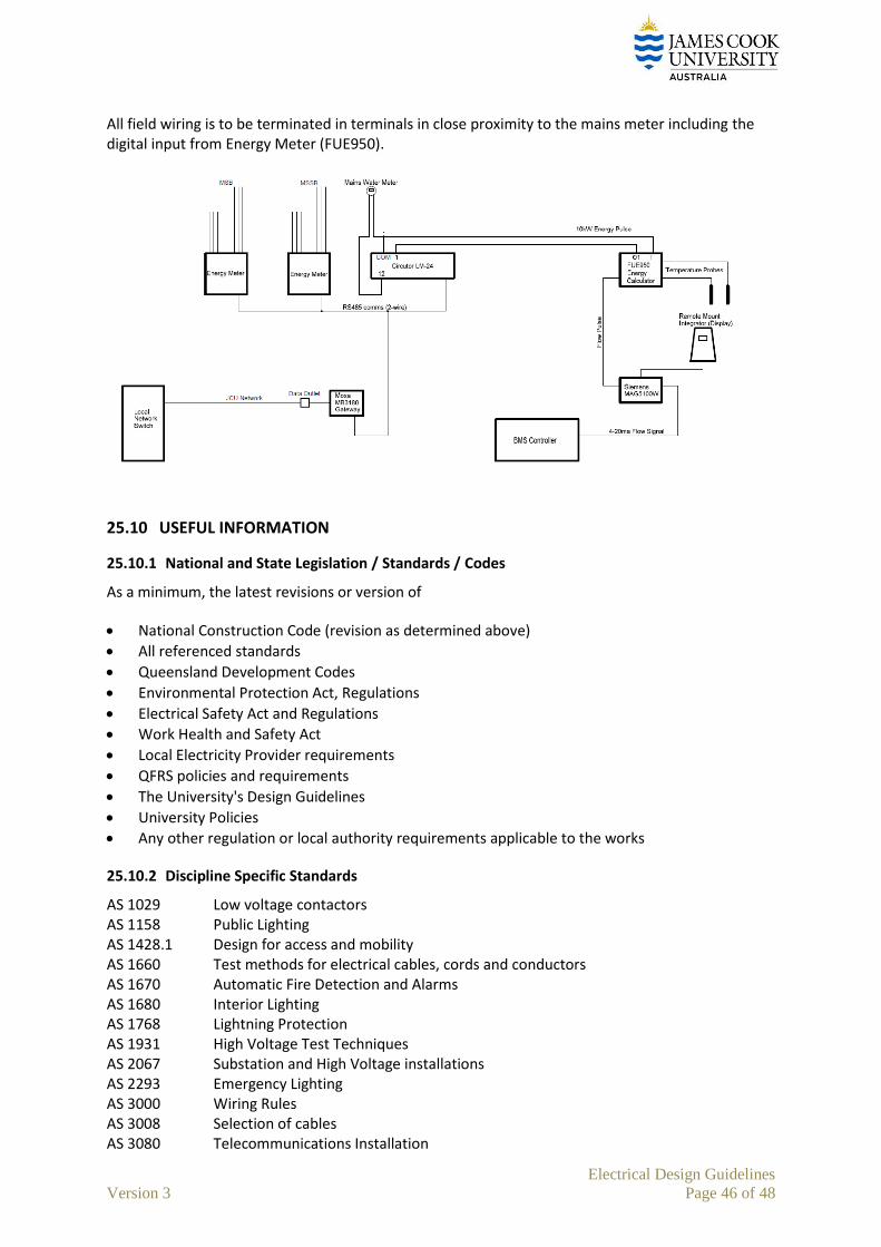
Electrical Design Guidelines
Version 3 Page 46 of 48
All field wiring is to be terminated in terminals in close proximity to the mains meter including the digital input from Energy Meter (FUE950).
25.10 USEFUL INFORMATION
25.10.1 National and State Legislation / Standards / Codes
As a minimum, the latest revisions or version of
National Construction Code (revision as determined above)
All referenced standards
Queensland Development Codes
Environmental Protection Act, Regulations
Electrical Safety Act and Regulations
Work Health and Safety Act
Local Electricity Provider requirements
QFRS policies and requirements
The University's Design Guidelines
University Policies
Any other regulation or local authority requirements applicable to the works
25.10.2 Discipline Specific Standards
AS 1029 Low voltage contactors AS 1158 Public Lighting AS 1428.1 Design for access and mobility AS 1660 Test methods for electrical cables, cords and conductors AS 1670 Automatic Fire Detection and Alarms AS 1680 Interior Lighting AS 1768 Lightning Protection AS 1931 High Voltage Test Techniques AS 2067 Substation and High Voltage installations AS 2293 Emergency Lighting AS 3000 Wiring Rules AS 3008 Selection of cables AS 3080 Telecommunications Installation

Electrical Design Guidelines
Version 3 Page 47 of 48
AS 3100 Approval and test specification - general requirements for electrical equipment AS 3200 Approval and test specification - Medical Electrical Equipment AS 3439 LV Switchgear Assemblies AS 60079 Electrical apparatus for explosive gas atmospheres AS/ACIF s 009 Installation Requirements for customer cabling (wiring rules)
Regardless of the above, any applicable standard is to be considered in the design. The term “AS” shall also refer to “AS/NZS”
25.10.3 Interfaces
Further to 25.3.2, as a minimum:
25.10.3.1 General
Ensure that all works necessary for the complete installation and successful operation are arranged with other trades. Ensure also that information required to accurately design the electrical services is obtained from other trades as required.
As a minimum:
25.10.3.2 Architectural Services
Switchroom and communications room sizing and location
Services cupboards or room sizing and location
Locations of switchboards and computer/server rooms
Service clearances
Cutouts for services
Penetrations, trenching, etc
Access panels requirements
25.10.3.3 Mechanical Engineering
Location and requirement of power supplies to mechanical equipment, exhaust fans and MSSBs
Advise on electrical motor sizing and circuit breaker sizing
Requirement of power for smoke control equipment and fans
Requirements for FIP interface for shutdown signals
Requirements for plantroom and external plant deck lighting and power points
Requirements for data points for connection to BMS controls etc
Coordination of in ceiling services and clash detection exercise
Interfaces to motion detectors etc for initiation of plant
25.10.3.4 Structural Engineering
Floor and wall penetrations
In floor trenches or ducts
25.10.3.5 Sprinklers
Location and rating of sprinkler pumps
Monitoring of sprinkler equipment on the FIP
25.10.3.6 Hydraulic Engineering
Location and rating of hydraulic control panels or equipment.
Requirements for sensor taps and urinal sensor.

Electrical Design Guidelines
Version 3 Page 48 of 48
Location of drinking fountains
Location and rating of hot water units and boiling water units
Location of gas solenoid valves and shutdown control
25.10.3.7 Lift Engineering
Location and rating of power supply
Requirement of security and phone in the lift car
25.10.3.8 Hazardous Areas Design
Review the Hazardous Area Classification for the space and address requirements (for example minimum ventilation rates, fresh air dilution etc)
Where required, arrange for electrical design for Hazardous Areas
Where potentially flammable or explosive liquids, gases, vapours or dusts are advised, advise the Estate Office of such presence and confirm whether a Hazardous Area Classification is required.