SECTION 233600 - AIR TERMINAL UNITS AND AIR DEVICES
23
University of Maryland, Baltimore Bressler Research Building – Seventh Floor Renovation Project No: 10-357 95% Construction Document Submission Phase March 11, 2011 AIR TERMINAL UNITS AND AIR DEVICES 233600- 1 SECTION 233600 – AIR TERMINAL UNITS AND AIR DEVICES Latest Update: 09-10-2021 See Underlined Text for Latest Edits (Engineer shall edit specifications and blue text in header to meet project requirements. This includes but is not lim- ited to updating Equipment and/or Material Model Numbers indicated in the specifications and adding any addition- al specifications that may be required by the project. Also turn off all “Underlines”.) PART 1 - GENERAL 1.1 RELATED DOCUMENTS A. Drawings and general provisions of the Contract, including General and Supplementary Conditions and Division 01 Specification Sections, apply to this section and all other sections of Division 23. 1.2 SUMMARY A. This section includes the requirements for air terminal units and air devices as follows: <Modify for specific project.> 1. Single duct terminal units. 2. Dual duct air terminal units. 3. Fan powered air terminal units. 4. Active chilled beam units 5. Exhaust terminal units. 6. Square ceiling diffuser. 7. Perforated Diffuser. 8. Linear slot diffuser. 9. Adjustable bar register. 10. Fixed face register. 11. Perforated return/exhaust grille. 12. Linear slot return. 13. Egg crate return. 14. Light troffer diffusers. 1.3 ACTION SUBMITTALS A. Product Data: Provide product data for terminal units and air devices as follows: 1. Air Terminal Units: Include: a. Include construction details, material descriptions, dimensions of individual components and profiles, and finishes for air terminal units. b. Include rated capacities, operating characteristics, sound-power ratings, furnished specialties and accessories. 2. Air Devices: Include:
Transcript of SECTION 233600 - AIR TERMINAL UNITS AND AIR DEVICES

University of Maryland, Baltimore Bressler Research Building – Seventh Floor Renovation Project No: 10-357 95% Construction Document Submission Phase March 11, 2011
AIR TERMINAL UNITS AND AIR DEVICES 233600- 1
SECTION 233600 – AIR TERMINAL UNITS AND AIR DEVICES Latest Update: 09-10-2021 See Underlined Text for Latest Edits (Engineer shall edit specifications and blue text in header to meet project requirements. This includes but is not lim-ited to updating Equipment and/or Material Model Numbers indicated in the specifications and adding any addition-al specifications that may be required by the project. Also turn off all “Underlines”.)
PART 1 - GENERAL
1.1 RELATED DOCUMENTS
A. Drawings and general provisions of the Contract, including General and Supplementary Conditions and Division 01 Specification Sections, apply to this section and all other sections of Division 23.
1.2 SUMMARY
A. This section includes the requirements for air terminal units and air devices as follows: <Modify for specific project.> 1. Single duct terminal units. 2. Dual duct air terminal units. 3. Fan powered air terminal units. 4. Active chilled beam units 5. Exhaust terminal units. 6. Square ceiling diffuser. 7. Perforated Diffuser. 8. Linear slot diffuser. 9. Adjustable bar register. 10. Fixed face register. 11. Perforated return/exhaust grille. 12. Linear slot return. 13. Egg crate return. 14. Light troffer diffusers.
1.3 ACTION SUBMITTALS
A. Product Data: Provide product data for terminal units and air devices as follows:
1. Air Terminal Units: Include: a. Include construction details, material descriptions, dimensions of
individual components and profiles, and finishes for air terminal units. b. Include rated capacities, operating characteristics, sound-power ratings,
furnished specialties and accessories.
2. Air Devices: Include:

University of Maryland, Baltimore Bressler Research Building – Seventh Floor Renovation Project No: 10-357 95% Construction Document Submission Phase March 11, 2011
AIR TERMINAL UNITS AND AIR DEVICES 233600- 2
a. Indicate materials of construction, finish, and mounting details; and performance data including throw and drop, static-pressure drop, and sound-power ratings.
b. Diffuser Schedule: Indicate drawing designation, room location, quantity, model number, size, and accessories furnished
B. LEED Submittals: <Delete if not LEED project.> 1. Product Data for Prerequisite IEQ 1: Documentation indicating that units comply
with ASHRAE 62.1, Section 5 - "Systems and Equipment."
C. Shop Drawings: For air terminal units. Include plans, elevations, sections, details, and attachments to other work. 1. Detail equipment assemblies and indicate dimensions, weights, loads, required
clearances, method of field assembly, components, and location and size of each field connection.
2. Wiring Diagrams: For power, signal, and control wiring. 3. Hangers and supports, including methods for duct and building attachment
[, seismic restraints,] and vibration isolation.
D. Delegated-Design Submittal: <Modify for specific project.> 1. Materials, fabrication, assembly, and spacing of hangers and supports. 2. Design Calculations: Calculations [, including analysis data signed and sealed by
the qualified professional engineer responsible for their preparation] for selecting hangers and supports [and seismic restraints].
E. Coordination Drawings: Reflected ceiling plans, drawn to scale, on which the following items are shown and coordinated with each other, using input from Installers of the items involved:
1. Ceiling suspension assembly members. 2. Size and location of initial access modules for acoustic tile. 3. Ceiling-mounted items including lighting fixtures, diffusers, grilles, speakers,
sprinklers, access panels, and special moldings.
1.4 INFORMATIONAL SUBMITTALS
A. Field quality-control reports.
1.5 CLOSEOUT SUBMITTALS
A. Operation and Maintenance Data: Include a copy of each approved submittal along with any applicable maintenance data in the project operation and maintenance manual.
B. Maintenance Material Submittals:
University of Maryland, Baltimore Bressler Research Building – Seventh Floor Renovation Project No: 10-357 95% Construction Document Submission Phase March 11, 2011
AIR TERMINAL UNITS AND AIR DEVICES 233600- 3
1. Furnish extra materials that match products installed and that are packaged with
protective covering for storage and identified with labels describing contents. a. Fan-Powered-Unit Filters: Furnish one spare filter(s) for each filter
installed.
1.6 QUALITY ASSURANCE
A. ASHRAE Compliance: Applicable requirements in ASHRAE 62.1, Section 5 - "Systems and Equipment" and Section 7 - "Construction and System Start-Up."
1.7 SEISMIC PERFORMANCE REQUIREMENTS < Delete if not Required>
A. Structural Performance: Hangers and supports and seismic restraints shall withstand the effects of gravity and seismic loads and stresses within limits and under conditions described in SMACNA's "HVAC Duct Construction Standards - Metal and Flexible" and SMACNA's "Seismic Restraint Manual: Guidelines for Mechanical Systems". 1. Seismic Hazard Level A: Seismic force to weight ratio, 0.48. 2. Seismic Hazard Level B: Seismic force to weight ratio, 0.30. 3. Seismic Hazard Level C: Seismic force to weight ratio, 0.15.
1.8 WARRANTY/GUARANTEE
A. See Division 23 Specification Section “Basic Mechanical Requirements – HVAC” for warranty and guarantee requirements.
PART 2 - PRODUCTS
2.1 GENERAL PRODUCT REQUIREMENTS
A. Supply and Exhaust Terminal Units: Terminal Units: Supply and exhaust air terminal units shall be, pressure independent type units, certified under ANSI/AHRI Standard 880 - 2011 Certification Program and carry the AHRI seal. Units shall be factory fabricated and tested. Selection shall be based on performance characteristics that match or exceed those indicated on the drawings. Air terminal units include units used for supply air, general exhaust air and fume hood exhaust air. 1. Terminal Unit Configurations: Terminal unit configurations shall be either RH or
LH when facing the unit’s inlet duct as indicated on the drawings and details.
B. Supply, Exhaust/Return Air Devices: Supply, exhaust/return air devices shall be tested in accordance with ANSI/ASHRAE Standard 70. Selections shall be based on performance characteristics that match or exceed those indicated on the drawings.

University of Maryland, Baltimore Bressler Research Building – Seventh Floor Renovation Project No: 10-357 95% Construction Document Submission Phase March 11, 2011
AIR TERMINAL UNITS AND AIR DEVICES 233600- 4
C. Active Chilled Beam Units: Active chilled beam units shall be rated in accordance with EN 15116. Selections shall be based on performance characteristics that match or exceed those indicated on the drawings.
2.2 SUPPLY TERMINAL UNITS
A. Basis of Design: The basis of design for supply terminal units shall be products manufactured by Titus, for single duct, dual, duct, or fan power unit applications, as indicated in the supply terminal unit model number schedule below.
B. Other Acceptable Manufacturers: Subject to compliance with requirements, provide supply terminal units by one of the following manufactures. See supply terminal unit model number schedule below for manufacturers model numbers.
1. Price Industries 2. MetalAire 3. Kruger 4. Environ Tech 5. Carnes 6. Nailor
C. Supply Terminal Unit Model Number Schedule: <Edit Schedule for terminal unit types for project requirements>
<Where unit type is not used, delete the model number and add N/A.>
Manufacturer Single Duct CV/VV
Dual Duct CV/VV
Fan Powered CV
Fan Powered VV
Titus DESV DEDV DTFS-F DTQP Price SDVQ DDUQ FDCGQ FDV Metal Aire TH-500 DH-500 FCI-600 FVI-500 Kruger LMHS LMHD KQFS QFS Environ Tech SDR N/A N/A N/A Nailor D3001/D30RW D3230 D35S D35N
D. Supply Terminal Units – Single Duct:
1. Construction and Sound Ratings:
a. Terminal Casing: 22 gauge galvanized steel.

University of Maryland, Baltimore Bressler Research Building – Seventh Floor Renovation Project No: 10-357 95% Construction Document Submission Phase March 11, 2011
AIR TERMINAL UNITS AND AIR DEVICES 233600- 5
b. Internal Lining: Internal Lining shall be a non - porous engineered polymer foam insulation closed foam fiber free (FF) cell insulation, 0.75 inch thick with a ‘R’ value three (3), fiberglass insulation will not be acceptable. Thermal conductivity shall meet or exceed 0.25 BTU - Inch / Hr. ft2 @ 75ºF. Insulation shall retain zero (0) moisture providing no support for bacterial or fungal growth and shall comply with the following: NFPA 90A, UL181 (Air Erosion), UL181 (Mold Growth and Humidity), UL723 (25/50 Flame and Smoke), ASTM E84 (25/50 Flame and Smoke), and CAN/ULC – 102.2-M88 (Flame and Smoke). Insulation shall be listed by Factory Mutual Research for compliance with all Codes, and Standards previously listed.
c. Discharge Connection: Galvanized steel slip and drive connections for square and/or rectangular ducts.
d. Casing Leakage: The unit casing shall be constructed to allow no more than 4 CFM while performing at one (1.0) inch inlet static pressure.
e. Damper: Heavy gauge steel with two (2) mechanical stops to prevent over stroking.
f. Damper Shaft: Solid steel with self-lubricating high density poly-ethylene bearings. Shaft shall be plainly marked to indicate damper position.
g. Damper Blade Seal: Full sheet synthetic to limit leakage to values specified in casing leakage data and no damper deflection.
h. Actuator: Factory mounted to the damper shaft and capable of providing a minimum of 35 lbs. of torque to the damper shaft. Refer to Division 23 Specification Sections for “Building Automatic Systems” for additional requirements.
i. Minimum Unit Static Pressure: The minimum static pressure required to operate each unit shall not exceed 0.13 inch wg for the basic unit with an inlet velocity of 2,000 fpm.
j. Integral Sound Attenuator: Slip and drive discharge connection with 22 gauge galvanized steel casing with perforated metal liner and polymer enclosed acoustic media. The geometry of the silencer shall be designed for use with the Air Terminal to avoid added pressure drop and generated noise. Silencer/Air Terminal assembly shall be tested and performance certified in accordance with ASHRAE 130-2008 and AHRI 880-2011.
k. Sound Ratings: Include sound rating documentation in the submittal for each unit size. The maximum scheduled noise criteria (NC Level) is for discharge and radiated sound and shall not be exceeded in any of the 2nd through 7th octave bands at the scheduled inlet static pressure (min 1.50 inches, unless otherwise noted). For computation of the terminal unit NC values do not include manufacturer’s standard cataloged attenuation credits. Include attenuation credits based solely on the actual design arrangement with respect to the layouts for ductwork and air devices served by each terminal as well as the actual room construction. Using the raw sound data from the terminal unit only, add credits based on the actual

University of Maryland, Baltimore Bressler Research Building – Seventh Floor Renovation Project No: 10-357 95% Construction Document Submission Phase March 11, 2011
AIR TERMINAL UNITS AND AIR DEVICES 233600- 6
design, where the NC values exceed the scheduled noise criteria provide sound attenuators to meet the scheduled NC values.
2. Accessories:
a. Control Enclosure: Provide a factory mounted 22 gage galvanized steel control enclosure with a removal cover to access the actuator, damper assembly and control components.
b. Coil Access: Provide a 9 inch x 6 inch gasketed removable panel to access the air flow inlet side of reheat coil. Locate the access panel, for the reheat coil on the bottom of the terminal casing. Access panel shall not leak in excess of the posted rating under the casing leakage requirements listed above.
c. Removable Air Flow Sensor: The air flow sensor shall be of a cross configuration located at the inlet of the assembly. The sensor shall have multi-point pressure sensing ports and a center averaging chamber designed to accurately average the flow across the inlet of the assembly. Sensor shall provide accuracy within 5% with a 90° sheet metal elbow directly at the inlet of the assembly so that straight lengths of duct are not required. Air flow sensor shall be removable for inspection and cleaning without disconnecting the inlet duct and/or the terminal unit as follows: 1) Titus Units: Sensor shall be removable from the bottom of the inlet
connection regardless of unit’s configuration. 2) Price Units: Sensor shall be removable from the side of the inlet
connection depending on the unit’s configuration. 3) Metal Aire Units: Sensor shall be removable side of the inlet
connection depending on the unit’s configuration. 4) Krueger Units; Sensor shall be removable from the side of the inlet
connection depending on the unit’s configuration. 5) Environ Tech Units: Sensor shall be removable side of the inlet
connection depending on the unit’s configuration. 6) Nailor Units: Sensor shall be removable from the side of the inlet
connection depending on the unit’s configuration.
3. Hot Water Heating Coils:
a. Casing: 20 gauge galvanized steel, factory mounted on terminal unit. b. Fins: Rippled and corrugated heavy gauge aluminum mechanically bonded
to the tubes. c. Tubes: Tubes shall be constructed with a 0.035 wall thickness with male
header and solder ends. d. Connections: Flanged or slip and drive. e. Testing: Leak test to 300 psi with minimum burst pressure of 2,000 psi. f. Performance: Meet scheduled capacity in accordance with ARI Standard
410.

University of Maryland, Baltimore Bressler Research Building – Seventh Floor Renovation Project No: 10-357 95% Construction Document Submission Phase March 11, 2011
AIR TERMINAL UNITS AND AIR DEVICES 233600- 7
g. Rows: All coils shall be two (2) row, multi circuited coils.
4. Control Components:
a. All control components shall be furnished and field installed by the BAS contractor, unless otherwise directed by UMB.
E. Supply Terminal Units – Dual Duct: <Selection of constant volume or variable air volume must be determined> 1. Construction and Sound Ratings:
a. Terminal Casing: 22 gauge galvanized steel. b. Internal Lining: Internal Lining shall be a non - porous engineered
polymer foam insulation closed foam fiber free (FF) cell insulation, 0.75 inch thick with a ‘R’ value three (3), fiberglass insulation will not be acceptable. Thermal conductivity shall meet or exceed 0.25 BTU - Inch / Hr. ft2 @ 75ºF. Insulation shall retain zero (0) moisture providing no support for bacterial or fungal growth and shall comply with the following: NFPA 90A, UL181 (Air Erosion), UL181 (Mold Growth and Humidity), UL723 (25/50 Flame and Smoke), ASTM E84 (25/50 Flame and Smoke), and CAN/ULC – 102.2-M88 (Flame and Smoke). Insulation shall be listed by Factory Mutual Research for compliance with all Codes, and Standards previously listed.
c. Mixing Chamber: Integral mixer-attenuator. d. Discharge Connection: Galvanized steel flanged connection for
rectangular ducts. e. Air Inlets and Outlets: Two (2) inch long galvanized steel round duct
collars with velocity sensors for each inlet. If available provide a velocity sensor for the outlet. All sensors shall connect to the controller.
f. Casing Leakage: The unit casing shall be constructed to allow no more than 4 CFM while performing at 1.0 inch inlet static pressure.
g. Damper: Heavy gauge steel with two (2) metal stops to prevent over-stroking.
h. Damper Shaft: Solid steel with self-lubricating high density polyethylene bearings. Shaft shall be plainly marked to indicate damper position.
i. Damper Blade Seal: Full sheet synthetic to limit leakage to values specified in casing leakage data and no damper deflection.
j. Actuator: Factory mounted to the damper shaft and capable of providing a minimum of 35 lbs. of torque to the damper shaft. Refer to Automatic Temperature Controls for additional requirements.
k. Minimum Unit Static Pressure: The minimum static pressure required to operate each unit shall not exceed 0.13 inch wg for the basic unit with an inlet velocity of 2,000 fpm.
l. Integral Sound Attenuator: Slip and drive discharge connection with 22 gauge galvanized steel casing with perforated metal liner and polymer

University of Maryland, Baltimore Bressler Research Building – Seventh Floor Renovation Project No: 10-357 95% Construction Document Submission Phase March 11, 2011
AIR TERMINAL UNITS AND AIR DEVICES 233600- 8
enclosed acoustic media. The geometry of the silencer shall be designed for use with the Air Terminal to avoid added pressure drop and generated noise. Silencer/Air Terminal assembly shall be tested and performance certified in accordance with ASHRAE 130-2008 and AHRI 880-2011.
m. Sound Ratings: Include sound rating documentation in the submittal for each unit size. The maximum scheduled noise criteria (NC Level) is for discharge and radiated sound and shall not be exceeded in any of the 2nd through 7th octave bands at the scheduled inlet static pressure (min 1.50 inches, unless otherwise noted). For computation of the terminal unit NC values do not include manufacturer’s standard cataloged attenuation credits. Include attenuation credits based solely on the actual design arrangement with respect to the layouts for ductwork and air devices served by each terminal as well as the actual room construction. Using the raw sound data from the terminal unit only, add credits based on the actual design, where the NC values exceed the scheduled noise criteria provide sound attenuators to meet the scheduled NC values.
2. Accessories: a. Control Enclosure: Provide a factory mounted 22 gage galvanized steel
control enclosure with a removal cover to access the actuator, damper assembly and control components.
b. Actuator and Damper Access: Provide gasketed removable panels to access the actuator and damper assembly. Locate the access panel on the bottom of the terminal casing. Access panel shall not leak in excess of the posted rating under the casing leakage requirements listed above.
c. Removable Air Flow Sensor: The air flow sensor shall be of a cross configuration located at the inlet of the assembly. The sensor shall have multi-point pressure sensing ports and a center averaging chamber designed to accurately average the flow across the inlet of the assembly. Sensor shall provide accuracy within 5% with a 90° sheet metal elbow directly at the inlet of the assembly so that straight lengths of duct are not required. Air flow sensor shall be removable for inspection and cleaning without disconnecting the inlet duct and /or the terminal unit as follows: 1) Titus Units: Sensor shall be removable from the bottom of the inlet
connection regardless of unit’s configuration. 2) Price Units: Sensor shall be removable from the side of the inlet
connection depending on the unit’s configuration. 3) Metal Aire Units: Sensor shall be removable side of the inlet
connection depending on the unit’s configuration. 4) Krueger Units; Sensor shall be removable from the side of the inlet
connection depending on the unit’s configuration. 5) Environ Tech Units: N/A 6) Nailor Units: Sensor shall be removable from the side of the inlet
connection depending on the unit’s configuration.

University of Maryland, Baltimore Bressler Research Building – Seventh Floor Renovation Project No: 10-357 95% Construction Document Submission Phase March 11, 2011
AIR TERMINAL UNITS AND AIR DEVICES 233600- 9
3. Control Components:
a. All control components shall be furnished and field installed by the BAS contractor, unless otherwise directed by UMB.
F. Supply Terminal Units – Fan Powered: <Selection of Parallel or Series units must be determined. Parallel flow units require a higher static pressure to allow the fan to not operate during low load conditions where the air is passed through the terminal to the air distribution system. Series flow units depend on the fan to mix primary air and plenum air with the fan in constant volume operation > 1. Construction and Sound Ratings:
a. Terminal Casing: 20 gauge galvanized steel. b. Internal Lining: Internal Lining shall be a non - porous engineered
polymer foam insulation closed foam fiber free (FF) cell insulation, 0.75 inch thick with a ‘R’ value three (3), fiberglass insulation will not be acceptable. Thermal conductivity shall meet or exceed 0.25 BTU - Inch / Hr. ft2 @ 75ºF. Insulation shall retain zero (0) moisture providing no support for bacterial or fungal growth and shall comply with the following: NFPA 90A, UL181 (Air Erosion), UL181 (Mold Growth and Humidity), UL723 (25/50 Flame and Smoke), ASTM E84 (25/50 Flame and Smoke), and CAN/ULC – 102.2-M88 (Flame and Smoke). Insulation shall be listed by Factory Mutual Research for compliance with all Codes, and Standards previously listed.
c. Backdraft Damper: Internal gasketed type. d. Discharge Connection: Flanged rectangular. e. Primary Air Inlet: Round two (2) inch long duct collar. f. Plenum Air Inlet: Rectangular with MERV 8 filter and boot. g. Casing Leakage: The casing leakage shall be equal to or less than the
factory tested label affixed to each air terminal per project specifications. h. Damper: Heavy gauge steel with two (2) metal stops to prevent over-
stroking. i. Damper Shaft: Solid steel with self-lubricating polyethylene bearings.
Shaft shall be plainly marked to indicate damper position. j. Damper Blade Seal: Full sheet synthetic to limit leakage to values
specified in casing leakage data and no damper deflection. k. Actuator: Factory mounted to the damper shaft and capable of providing a
minimum of 35 lbs. of torque to the damper shaft. Refer to Automatic Temperature Controls for additional requirements.
l. Minimum Unit Static Pressure: The minimum static pressure required to operate each unit shall not exceed 0.13 inch wg for the basic unit with an inlet velocity of 2,000 fpm.
m. Integral Sound Attenuator: Connections shall be 22 gauge galvanized slip and drive inlet and discharge connections. Perforated metal liner and polymer enclosed acoustic media on discharge. The geometry of the

University of Maryland, Baltimore Bressler Research Building – Seventh Floor Renovation Project No: 10-357 95% Construction Document Submission Phase March 11, 2011
AIR TERMINAL UNITS AND AIR DEVICES 233600- 10
silencer shall be designed for use with the Air Terminal to avoid added pressure drop and generated noise. Silencer/Air Terminal assembly shall be tested and performance certified in accordance with ASHRAE 130-2008 and AHRI 880-2011.
n. Sound Ratings: Include sound rating documentation in the submittal for each unit size. The maximum scheduled noise criteria (NC Level) is for discharge and radiated sound and shall not be exceeded in any of the 2nd through 7th octave bands at the scheduled inlet static pressure (min 1.50 inches, unless otherwise noted). For computation of the terminal unit NC values do not include manufacturer’s standard cataloged attenuation credits. Include attenuation credits based solely on the actual design arrangement with respect to the layouts for ductwork and air devices served by each terminal as well as the actual room construction. Using the raw sound data from the terminal unit only, add credits based on the actual design, where the NC values exceed the scheduled noise criteria provide sound attenuators to meet the scheduled NC values.
2. Fan and Motor: a. Fan: Forward curved, steel construction with direct drive high efficiency,
permanent split capacitor, integral thermal overload protection motor with SCR fan adjustment control. Fan shall be equipped with anti-backward rotation device and vibration isolation.
b. Motor: Comply with NEMA designation, temperature rating, service factor, enclosure type, and efficiency requirements for motors specified in Section "Common Motor Requirements for HVAC Equipment."
3. Accessories: a. Control Enclosure: Provide a factory mounted 22 gauge galvanized steel
control enclosure with a removal cover to access the actuator, damper assembly and control components.
b. Fan, Actuator and Damper Access: Provide gasketed removable panels to access the fan, actuator and damper assembly. Locate the access panel on the bottom of the terminal casing. Access panel shall not leak in excess of the posted rating under the casing leakage requirements listed above.
c. Removable Air Flow Sensor: The air flow sensor shall be of a cross configuration located at the inlet of the assembly. The sensor shall have multi-point pressure sensing ports and a center averaging chamber designed to accurately average the flow across the inlet of the assembly. Sensor shall provide accuracy within 5% with a 90° sheet metal elbow directly at the inlet of the assembly so that straight lengths of duct are not required. Air flow sensor shall be removable for inspection and cleaning without disconnecting the inlet duct and/or the terminal unit as follows:
University of Maryland, Baltimore Bressler Research Building – Seventh Floor Renovation Project No: 10-357 95% Construction Document Submission Phase March 11, 2011
AIR TERMINAL UNITS AND AIR DEVICES 233600- 11
1) Titus Units: Sensor shall be removable from the bottom of the inlet connection regardless of unit’s configuration.
2) Price Units: Sensor shall be removable side of the inlet connection depending on the unit’s configuration.
3) Metal Aire Units: Sensor shall be removable side of the inlet connection depending on the unit’s configuration.
4) Krueger Units; Sensor shall be removable side of the inlet connection depending on the unit’s configuration.
5) Environ Tech Units: N/A 6) Nailor Units: Sensor shall be removable side of the inlet
connection depending on the unit’s configuration.
4. Hot Water Heating Coils:
a. Casing: 20 gauge galvanized steel, factory mounted on terminal unit. b. Fins: Rippled and corrugated heavy gauge aluminum mechanically bonded
to the tubes. c. Tubes: Tubes shall be constructed with a 0.035 wall thickness with male
header and solder ends. d. Connections: Flanged or slip and drive. e. Testing: Leak test to 300 psi with minimum burst pressure of 2,000 psi. f. Performance: Meet scheduled capacity in accordance with ARI Standard
410. g. Rows: All coils shall be two (2) row, multi circuited coils.
5. Control Components for:
a. All control components shall be furnished and field installed by the BAS
contractor, unless otherwise directed by UMB. b. Factory-Mounted and -Wired Controls: Electrical components mounted in
control box with removable cover. Incorporate single-point electrical connection to power source.
c. Control Transformer: Factory mounted for control voltage on electric and electronic control units with terminal strip in control box for field wiring of thermostat and power source.
d. Wiring Terminations: Fan and controls to terminal strip. Terminal lugs to match quantities, sizes, and materials of branch-circuit conductors. Enclose terminal lugs in terminal box that is sized according to NFPA 70.
e. Disconnect Switch: Factory-mounted, fuse type. f. Control Panel Enclosure: NEMA 250, Type 1, with access panel sealed
from airflow and mounted on side of unit.
2.3 CHILLED BEAM UNITS
A. Basis of Design: The basis of design is <Insert basis of design manufacturer and model>

University of Maryland, Baltimore Bressler Research Building – Seventh Floor Renovation Project No: 10-357 95% Construction Document Submission Phase March 11, 2011
AIR TERMINAL UNITS AND AIR DEVICES 233600- 12
B. Other Acceptable Manufacturers: Subject to compliance with requirements, provide
terminal units of one (1) of the following: <Edit for project insert manufacturer and model numbers >
1. Price Industries 2. MetalAire 3. Kruger 4. Environ Tech 5. Nailor
C. Chilled Beams: - Active:
1. Construction and Sound Ratings:
a. Terminal Casing: <Insert Spec Data> b. Air Plenum and Nozzle: <Insert Spec Data> c. Duct Connections: <Insert Spec Data> d. Sound Ratings: <Insert Spec Data>
2. Chilled Water and Hot Water Coils:
a. Casing: 20 gauge galvanized steel, factory mounted on terminal unit. b. Fins: Rippled and corrugated heavy gauge aluminum mechanically bonded
to the tubes. c. Tubes: Tubes shall be constructed with a 0.035 wall thickness with male
header and solder ends. d. Connections: Flanged or slip and drive. e. Testing: Leak test to 300 psi with minimum burst pressure of 2,000 psi. f. Performance: Meet scheduled capacity in accordance with ARI Standard
410.
3. Accessories: <Insert Spec Data> 4. Control Components: All control components shall be furnished and field
installed by the BAS contractor.
2.4 EXHAUST TERMINAL UNITS
A. Basis of Design: The basis of design for exhaust terminal units shall be products manufactured by Titus for round duct and square/rectangular duct applications as indicated in the exhaust unit model number schedule below.
University of Maryland, Baltimore Bressler Research Building – Seventh Floor Renovation Project No: 10-357 95% Construction Document Submission Phase March 11, 2011
AIR TERMINAL UNITS AND AIR DEVICES 233600- 13
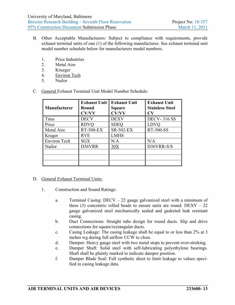
B. Other Acceptable Manufacturers: Subject to compliance with requirements, provide exhaust terminal units of one (1) of the following manufactures. See exhaust terminal unit model number schedule below for manufacturers model numbers.
1. Price Industries 2. Metal Aire 3. Krueger 4. Environ Tech 5. Nailor
C. General Exhaust Terminal Unit Model Number Schedule:
Manufacturer Exhaust Unit Round CV/VV
Exhaust Unit Square CV/VV
Exhaust Unit Stainless Steel CV
Titus DECV DEXV DECV- 316 SS Price RDVQ SDEQ LDVQ Metal Aire RT-500-EX SR-502-EX RT-500-SS Kruger RVE LMHS Environ Tech SGX N/A N/A Nailor D36VRR 30X D36VRR-S/S
D. General Exhaust Terminal Units: 1. Construction and Sound Ratings:
a. Terminal Casing: DECV – 22 gauge galvanized steel with a minimum of
three (3) concentric rolled beads to ensure units are round. DEXV – 22 gauge galvanized steel mechanically sealed and gasketed leak resistant casing.
b. Duct Connections: Straight tube design for round ducts. Slip and drive connections for square/rectangular ducts.
c. Casing Leakage: The casing leakage shall be equal to or less than 2% at 3 inches wg during full airflow CCW to close.
d. Damper: Heavy gauge steel with two metal stops to prevent over-stroking. e. Damper Shaft: Solid steel with self-lubricating polyethylene bearings.
Shaft shall be plainly marked to indicate damper position. f. Damper Blade Seal: Full synthetic sheet to limit leakage to values speci-
fied in casing leakage data.

University of Maryland, Baltimore Bressler Research Building – Seventh Floor Renovation Project No: 10-357 95% Construction Document Submission Phase March 11, 2011
AIR TERMINAL UNITS AND AIR DEVICES 233600- 14
g. Actuator: Factory mounted to the damper shaft and capable of providing a minimum of 35 lbs. of torque to the damper shaft. Refer to Automatic Temperature Controls for additional requirements.
h. Minimum Unit Static Pressure: The minimum static pressure required to operate each unit shall not exceed 0.32 inch wg for the basic unit with an outlet velocity of 2,000 fpm.
i. Sound Attenuator: Slip and drive discharge connection with 22 gauge gal-vanized steel casing with perforated metal liner and polymer enclosed acoustic media. The geometry of the silencer shall be designed for use with the Air Terminal to avoid added pressure drop and generated noise. Silencer/Air Terminal assembly shall be tested and performance certified in accordance with ASHRAE 130-2008 and AHRI 880-2011. Provide sound attenuators as follows: 1) Round Exhaust Terminals: Non – integral sound attenuator for
mounting in rectangular or square ducts. 2) Square Exhaust Terminals: Integral sound attenuator.
j. Sound Ratings: Include sound rating documentation in the submittal for each unit size. The maximum scheduled noise criteria (NC Level) is for discharge and radiated sound and shall not be exceeded in any of the 2nd through 7th octave bands at the scheduled inlet static pressure (min 1.50 inches, unless otherwise noted). For computation of the terminal unit NC values do not include manufacturer’s standard cataloged attenuation cred-its. Include attenuation credits based solely on the actual design arrange-ment with respect to the layouts for ductwork and air devices served by each terminal as well as the actual room construction. Using the raw sound data from the terminal unit only, add credits based on the actual design, where the NC values exceed the scheduled noise criteria provide sound at-tenuators to meet the scheduled NC values.
2. Accessories: a. Control Enclosure: Provide a factory mounted 22 gage galvanized steel
control enclosure with a removal cover to access the actuator, damper as-sembly and control components.
b. Removable Air Flow Sensor: The air flow sensor shall be of a cross con-figuration located at the inlet of the assembly. The sensor shall have multi-point pressure sensing ports and a center averaging chamber designed to accurately average the flow across the inlet of the assembly. Sensor shall provide accuracy within 5% with a 90° sheet metal elbow directly at the inlet of the assembly so that straight lengths of duct are not required. Air flow sensor shall be removable for inspection and cleaning without dis-connecting the inlet duct and/or the terminal unit as follows:
University of Maryland, Baltimore Bressler Research Building – Seventh Floor Renovation Project No: 10-357 95% Construction Document Submission Phase March 11, 2011
AIR TERMINAL UNITS AND AIR DEVICES 233600- 15
1) Titus Units: Sensor shall be removable from the bottom of the inlet connection regardless of unit’s configuration.
2) Price Units: Sensor shall be removable from the side of the inlet connection depending on the unit’s configuration.
3) Metal Aire Units: Sensor shall be removable from the side of the inlet connection depending on the unit’s configuration.
4) Krueger Units; Sensor shall be removable from the side of the inlet connection depending on the unit’s configuration.
5) Enviro Tech Units: N/A 6) Nailor Units: Sensor shall be removable from the side of the inlet
connection depending on the unit’s configuration.
3. Control Components: a. All control components shall be furnished and field installed by the BAS
contractor, unless otherwise directed by UMB.
E. Fume Hood Exhaust Terminal Units:
1. Construction and Sound Ratings: a. Terminal Casing: DECV – Type 316 stainless steel with a minimum of
three (3) concentric rolled beads to ensure units are round. b. Duct Connections: Straight stainless steel tube design for round ducts. c. Casing Leakage: The casing leakage shall be equal to or less than 1% for
welded stainless casing. d. Damper: Heavy gauge stainless steel with two (2) mechanical stops to
prevent over stroking. e. Damper Shaft: Damper shaft shall solid 316 stainless steel construction
with self-lubricating Teflon bearings. Shaft shall be plainly marked to in-dicate damper position.
f. Damper Blade Seal: Seal material is also Teflon to limit leakage to values at zero and as specified in casing leakage data.
g. Actuator: Factory mounted to the damper shaft and capable of providing a minimum of 35 lbs. of torque to the damper shaft. Refer to Automatic Temperature Controls for additional requirements.
h. Minimum Unit Static Pressure: The minimum static pressure required to operate each unit shall not exceed 0.13 inch wg for the basic unit with an outlet velocity of 2,000 fpm.
2. Accessories:
a. Control Enclosure: Provide a factory mounted 22 gauge galvanized steel
control enclosure with a removal cover to access the actuator, damper as-sembly and control components. Where the panel is attached to the termi-

University of Maryland, Baltimore Bressler Research Building – Seventh Floor Renovation Project No: 10-357 95% Construction Document Submission Phase March 11, 2011
AIR TERMINAL UNITS AND AIR DEVICES 233600- 16
nal provide neoprene gaskets to separate galvanized material from stain-less steel material.
b. Removable Air Flow Sensor: Velocity sensor shall be a cross pattern type sensor constructed with type 316 stainless steel. Sensor shall also remova-ble for cleaning and inspection. Air flow sensor shall be removable for in-spection and cleaning without disconnecting the inlet duct and/or the ter-minal unit as follows: 1) Titus Units: Sensor shall be removable from the bottom of the inlet
connection regardless of unit’s configuration. 2) Price Units: Sensor shall be removable from the side of the inlet
connection depending on the unit’s configuration. 3) Metal Aire Units: Sensor shall be removable side of the inlet
connection depending on the unit’s configuration. 4) Krueger Units; Sensor shall be removable from the side of the inlet
connection depending on the unit’s configuration. 5) Enviro Tech Units: N/A 6) Nailor Units: Sensor shall be removable from the side of the inlet
connection depending on the unit’s configuration.
3. Control Components: a. All control components shall be furnished and field installed by the BAS
contractor, unless otherwise directed by UMB.
2.5 SUPPLY AIR DEVICES
A. Basis of Design: The basis of design for air devices is as follows: 1. Square Ceiling Diffusers: Titus Model – TDC, TDCA, PAS. <Edit for Project> 2. Linear Slot Diffusers: Titus Model – TBD – 80, TBDI - 80 <Delete or Edit for
Project> 3. Adjustable Bar Register: Titus Model – 300, 301 <Delete or Edit for Project>
B. Other Acceptable Manufacturers: Subject to compliance with requirements, provide air devices of one (1) of the following:
1. Price Industries 2. Metal Aire 3. Kruger 4. Envirotec 5. Nailor
C. Square Ceiling Diffusers: 1. Material: Steel or Aluminum. 2. Module Size: twenty four (24) x twenty four (24). 3. Finish: Number twenty six (26) white baked enamel finish.
University of Maryland, Baltimore Bressler Research Building – Seventh Floor Renovation Project No: 10-357 95% Construction Document Submission Phase March 11, 2011
AIR TERMINAL UNITS AND AIR DEVICES 233600- 17
4. Face Style: Louvered. 5. Mounting: Snap in, Lay In, hard ceiling and/or Spline. 6. Pattern: One (1), two (2), three (3) or four (4) way blow as scheduled. 7. Dampers: opposed blade or butterfly damper with eight (8) inches of hard duct
prior to damper. 8. Accessories: Throw reducing vanes.
D. Perforated Diffuser:
1. Material: Steel or aluminum frame and perforated face with three sixteenth (3/16)
inch diameter holes on one quarter (1/4) inch staggered centers with a free area of not less than 51%.
2. Back Pan: One piece stamped steel pan. 3. Finish: Number twenty six (26) white baked enamel finish. 4. Duct Inlet: Round or Square. 5. Face Style: Flush. 6. Mounting: Surface T-bar Snap in Spline 4SL. 7. Pattern Controllers: Mounted on the back of the perforated face and be field
adjustable. 8. Dampers: Opposed blade. 9. Accessories: Equalizing grid.
E. Linear Slot Diffuser:
1. Material - Shell: Steel, insulated and noninsulated. 2. Material - Pattern Controller and Tees: Aluminum. 3. Finish - Face and Shell: Baked enamel, black. 4. Finish - Pattern Controller: Baked enamel, black. 5. Finish - Tees: Baked enamel, white. 6. Slot Width: Three quarter (3/4) inch, one (1) inch or one and one half (1-1/2)
inches. 7. Number of Slots: One (1), Two (2), Three (3), or Four (4) slots. 8. Length: Twenty four (24) inches, or forty eight (48) inches. 9. Accessories: Plaster frame, T-bar clip on one side.
2.6 EXHAUST/RETURN AIR DEVICES
A. Basis of Design: The basis of design for air devices is as follows: 1. Adjustable Bar Register: Titus Model – 300, 301 <Delete or Edit for Project> 2. Fixed Face Register: Titus Model – 350 R <Delete if not Required> 3. Perforated Face Grille: Titus Model – PAR <Delete if not Required> 4. Linear Slot Returns:” Titus Model – TBR 80 <Delete if not Required> 5. Egg Crate Grilles: Titus Model – 50F <Delete if not Required>

University of Maryland, Baltimore Bressler Research Building – Seventh Floor Renovation Project No: 10-357 95% Construction Document Submission Phase March 11, 2011
AIR TERMINAL UNITS AND AIR DEVICES 233600- 18
B. Other Acceptable Manufacturers: Subject to compliance with requirements, provide air devices of one (1) of the following:
1. Price Industries 2. Metal Aire 3. Kruger 4. Envirotec 5. Carnes 6. Nailor
C. Adjustable Bar Register: 1. Material: Steel Aluminum, Stainless steel. 2. Finish: Number twenty six (26) white baked enamel finish. 3. Face Blade Arrangement: Horizontal Vertical spaced three quarter (3/4) inch
apart. 4. Core Construction: Integral. 5. Rear-Blade Arrangement: Horizontal Vertical spaced three quarter (3/4) inch
apart. 6. Frame: One and one quarter (1-1/4) inches wide. 7. Mounting: Countersunk screw. 8. Damper Type: Adjustable opposed blade. 9. Accessories: Front Rear-blade gang operator.
D. Fixed Face Register: 1. Material: Steel, Aluminum, and Stainless Steel. 2. Finish: Number twenty six (26) white baked enamel finish. 3. Face Arrangement: Three quarter (3/4) inch spacing, deflection: 0. 35. 4. Core Construction: Integral. 5. Frame: One and one quarter (1-1/4) inches wide. 6. Mounting: Countersunk screw. 7. Damper Type: Adjustable opposed blade.
E. Perforated Return:
1. Face Material: Steel or aluminum perforated face with three sixteenth (3/16) inch diameter holes on one quarter (1/4) inch staggered centers with a free area of not less than 51%.
2. Back Pan: One piece stamped steel pan. 3. Finish: Number twenty six (26) white baked enamel finish. 4. Duct Inlet: Round or Square. 5. Face Style: Flush. 6. Mounting: Surface T-bar Snap in Spline 4SL. 7. Dampers: Opposed blade.

University of Maryland, Baltimore Bressler Research Building – Seventh Floor Renovation Project No: 10-357 95% Construction Document Submission Phase March 11, 2011
AIR TERMINAL UNITS AND AIR DEVICES 233600- 19
8. Accessories: Equalizing grid.
F. Linear Slot Return:
1. Material - Shell: Steel, non-insulated and with light shield. 2. Material - Pattern Controller and Tees: Aluminum. 3. Finish - Face and Shell: Baked enamel, black. 4. Finish - Pattern Controller: Baked enamel, black. 5. Finish - Tees: Baked enamel, white. 6. Slot Width: Three quarter (3/4) inch, one (1) inch or one and one half (1-1/2)
inches. 7. Number of Slots: One (1) or Two (2) slots. 8. Length: Twenty four (24) inches or forty eight (48) inches long. 9. Accessories: Plaster frame, T-bar clip on one side.
G. Egg Crate Return:
1. Material - Shell: Heavy gauge extruded aluminum, 0.040-0.050 inches thick with countersunk screw holes.
2. Grid: Aluminum grid with three (3) sizes available: <Edit for Project> a. One half (1/2) inch x one half (1/2) inch x one half (1/2) inch. b. One half (1/2) inch x one half (1/2) inch x one (1) inch. c. One (1) inch x one (1) inch x one (1) inch.
3. Minimum Free Area: The minimum free area must be not less than 90% free area. 4. Border Types: Surface mount or Lay in type. 5. Accessories: Opposed blade damper.
2.7 LIGHT TROFFER DIFFUSERS <Delete if not required >
<Engineer to insert product specification for Light Troffer Diffusers and coordinate required performance data with Division 26, Specification Section “Interior Lighting.>
2.8 SEISMIC-RESTRAINT DEVICES <Delete if not required.>
A. General Requirements for Restraint Components: Rated strengths, features, and applications shall be as defined in reports by an agency acceptable to authorities having jurisdiction.
1. Structural Safety Factor: Allowable strength in tension, shear, and pullout force of components shall be at least four times the maximum seismic forces to which they will be subjected.
B. Channel Support System: Shop- or field-fabricated support assembly made of slotted steel channels rated in tension, compression, and torsion forces and with accessories for

University of Maryland, Baltimore Bressler Research Building – Seventh Floor Renovation Project No: 10-357 95% Construction Document Submission Phase March 11, 2011
AIR TERMINAL UNITS AND AIR DEVICES 233600- 20
attachment to braced component at one end and to building structure at the other end. Include matching components and corrosion-resistant coating.
C. Restraint Cables: ASTM A 603, galvanized-steel cables with end connections made of cadmium-plated steel assemblies with brackets, swivel, and bolts designed for restraining cable service; with an automatic-locking and clamping device or double-cable clips.
D. Hanger Rod Stiffener: Steel tube or steel slotted-support-system sleeve with internally bolted connections to hanger rod.
E. Mechanical Anchor Bolts: Drilled-in and stud-wedge or female-wedge type. Select anchor bolts with strength required for anchor and as tested according to ASTM E 488.
PART 3 - EXECUTION
3.1 INSTALLATION
A. Install air terminal units according to NFPA 90A, "Standard for the Installation of Air Conditioning and Ventilating Systems."
B. Install air terminal unit’s level and plumb. Maintain sufficient clearance for normal service and maintenance.
C. Install diffusers, registers, and grilles level and plumb with the ceiling and or wall surface.
D. Ceiling-Mounted Outlets and Inlets: Drawings indicate general arrangement of ducts fittings, and accessories. Air outlet and inlet locations have been indicated to achieve design requirements for air volume, noise criteria, airflow pattern, throw, and pressure drop. Make final locations where indicated, as much as practical. For units installed in lay-in ceiling panels, locate units in the center of panel. Where architectural features or other items conflict with installation, notify Architect for a determination of final location.
E. Install diffusers, registers, and grilles with airtight connections to ducts and to allow service and maintenance of dampers, air extractors, and fire dampers.
3.2 ADJUSTING
A. After installation, adjust diffusers, registers, and grilles to air patterns indicated, or as directed, before starting air balancing.
3.3 HANGER AND SUPPORT INSTALLATION
A. Comply with SMACNA's "HVAC Duct Construction Standards - Metal and Flexible," Chapter 5, "Hangers and Supports."

University of Maryland, Baltimore Bressler Research Building – Seventh Floor Renovation Project No: 10-357 95% Construction Document Submission Phase March 11, 2011
AIR TERMINAL UNITS AND AIR DEVICES 233600- 21
B. Building Attachments: Concrete inserts, powder-actuated fasteners, or structural-steel fasteners appropriate for construction materials to which hangers are being attached.
1. Where practical, install concrete inserts before placing concrete. 2. Install powder-actuated concrete fasteners after concrete is placed and completely
cured. 3. Use powder-actuated concrete fasteners for standard-weight aggregate concretes
and for slabs more than four (4) inches thick. 4. Do not use powder-actuated concrete fasteners for lightweight-aggregate
concretes and for slabs less than four (4) inches thick. 5. Do not use powder-actuated concrete fasteners for seismic restraints.
C. Hangers Exposed to View: Threaded rod and angle or channel supports.
D. Install upper attachments to structures. Select and size upper attachments with pull-out, tension, and shear capacities appropriate for supported loads and building materials where used.
E. Air Terminal Unit Attachments: Sheet metal screws, blind rivets, or self-tapping metal screws; compatible with duct materials.
F. Trapeze and Riser Supports: Steel shapes and plates for units with steel casings; aluminum for units with aluminum casings.
3.4 SEISMIC-RESTRAINT-DEVICE INSTALLATION <Delete if not Required>
A. Install hangers and braces designed to support the air terminal units and to restrain against seismic forces required by applicable building codes. Comply with SMACNA's "Seismic Restraint Manual: Guidelines for Mechanical Systems."
B. Select seismic-restraint devices with capacities adequate to carry present and future static and seismic loads.
C. Install cables so they do not bend across edges of adjacent equipment or building structure.
D. Install cable restraints on air terminal units that are suspended with vibration isolators.
E. Install seismic-restraint devices using methods approved by an agency acceptable to authorities having jurisdiction.
F. Attachment to Structure: If specific attachment is not indicated, anchor bracing and restraints to structure, to flanges of beams, to upper truss chords of bar joists, or to concrete members.
G. Drilling for and Setting Anchors:
University of Maryland, Baltimore Bressler Research Building – Seventh Floor Renovation Project No: 10-357 95% Construction Document Submission Phase March 11, 2011
AIR TERMINAL UNITS AND AIR DEVICES 233600- 22
1. Identify position of reinforcing steel and other embedded items before drilling holes for anchors. Do not damage existing reinforcement or embedded items during drilling. Notify the Architect if reinforcing steel or other embedded items are encountered during drilling. Locate and avoid prestressed tendons, electrical and telecommunications conduit, and gas lines.
2. Do not drill holes in concrete or masonry until concrete, mortar, or grout has achieved full design strength.
3. Wedge Anchors: Protect threads from damage during anchor installation. Install heavy-duty sleeve anchors with sleeve fully engaged in the structural element to which anchor is to be fastened.
4. Set anchors to manufacturer's recommended torque, using a torque wrench. 5. Install zinc-coated steel anchors for interior applications and stainless-steel
anchors for applications exposed to weather.
3.5 CONNECTIONS
A. Install piping adjacent to air terminal unit to allow service and maintenance.
B. Hot-Water Piping: In addition to requirements in Division 23 Specification Section "HVAC Piping Systems and Specialties" connect heating coils to supply with shutoff valve, strainer, control valve, and union or flange; and to return with balancing valve and union or flange.
C. Connect ducts to air terminal units according to Division 23 Specification Section "HVAC Duct Systems and Accessories."
D. Make connections to air terminal units with flexible connectors complying with requirements in Division 23 Specification Section "HVAC Duct Systems and Accessories."
3.6 IDENTIFICATION
A. Label each air terminal unit with plan number, nominal airflow, and maximum and minimum factory-set airflows. Comply with requirements in Division 23 Specification Section "Identification for HVAC Systems and Equipment" for equipment labels and warning signs and labels.
3.7 FIELD QUALITY CONTROL
A. Testing Agency: Owner will engage a qualified testing agency to perform tests and inspections.
B. Manufacturer's Field Service: Engage a factory-authorized service representative to inspect, test, and adjust components, assemblies, and equipment installations, including connections.
University of Maryland, Baltimore Bressler Research Building – Seventh Floor Renovation Project No: 10-357 95% Construction Document Submission Phase March 11, 2011
AIR TERMINAL UNITS AND AIR DEVICES 233600- 23
C. Perform tests and inspections.
1. Manufacturer's Field Service: Engage a factory-authorized service representative to inspect components, assemblies, and equipment installations, including connections, and to assist in testing.
D. Tests and Inspections:
1. After installing air terminal units and after electrical circuitry has been energized, test for compliance with requirements.
2. Leak Test: After installation, fill water coils and test for leaks. Repair leaks and retest until no leaks exist.
3. Operational Test: After electrical circuitry has been energized, start units to confirm proper motor rotation and unit operation.
4. Test and adjust controls and safeties. Replace damaged and malfunctioning controls and equipment.
E. Air terminal unit will be considered defective if it does not pass tests and inspections.
F. Prepare test and inspection reports.
3.8 STARTUP SERVICE
A. Engage a factory-authorized service representative to perform startup service.
1. Complete installation and startup checks according to manufacturer's written instructions.
2. Verify that inlet duct connections are as recommended by air terminal unit manufacturer to achieve proper performance.
3. Verify that controls and control enclosure are accessible. 4. Verify that control connections are complete. 5. Verify that nameplate and identification tag are visible. 6. Verify that controls respond to inputs as specified.
3.9 DEMONSTRATION
A. Engage a factory-authorized service representative to train Owner's maintenance personnel to adjust, operate, and maintain air terminal units.
END OF SECTION 233600