Section 2.10 Spill Prevention and Control - Washington Savage/Application/2013... · Section 2.10...
18
Tesoro Savage Vancouver Energy Distribution Terminal January 2014 Application No. 2013-01 Supplement Page 2-135 Section 2.10 Spill Prevention and Control This section describes the spill prevention and control measures to be employed at the Facility regarding accidental and/or unauthorized discharges or emissions, especially as they relates to specific proposed Facility components, storage (locations, amounts duration), and modes of product handling from the time the crude oil enters the Facility to the time it is loaded to marine vessels. The nature of the proposed Facility (offloading from rail, storage, and loading to marine vessels) and the nature of the product handled (crude oil) engender a comprehensive and rigorous regulatory environment for Ffacility design, construction, operation, and spill response contingency planning. Local state and federal programs all regulate spill prevention of the proposed Ffacility and offer significant redundancy in safety protocols for the proposed Ffacility. The cooperation of local, state, and federal agencies, and industry spill response cooperatives has made Washington State a national leader in spill contingency planning and response. The Applicant will comply with the comprehensive regulatory context regarding Facility design, construction, operation, and contingency planning requirements and its actions will be fully coordinated to meet all applicable local, state, and federal requirements. The Applicant will also implement inspection and training processes to ensure long-term compliance with these requirements. Inspections and training relating to spill prevention and controls will be integrated into the overall day-to-day management of the Facility. Stormwater protection will also require spill pollution controls – these are addressed separately in Sections 2.11 and 5.3 of this Application. 2.10.1 Regulatory Overview and Applicability 2.10.1.1 Federal Requirements The federal regulatory structure for spill prevention, control, and contingency planning related to the storage and loading of crude oil to marine vessels has developed over time through the interaction of multiple federal law-making processes. Lawmaking has primarily involved the following three components to address these requirements: the establishment of the National Contingency Plan (NCP), the Clean Water Act (CWA), as amended, and the Oil Pollution Act of 1990 (OPA 90). Appendix B.1 provides a summary of how these three statutes have interacted since their inception to include requirements applicable to oil storage facilities and to oil transfer operations over marine waters, as well as the broader regional contingency planning effort. Spill Prevention and Control Section 311(j) of the CWA establishes the spill prevention and control requirements for three categories of facilities: related to transportation, not related to transportation, and complexes. What constitutes transportation-related versus non-transportation-related facilities has been established through a series of executive orders (EOs) and memoranda of understanding (MOUs) (EPA, 2005). Onshore and certain offshore non-transportation-related facilities (and portions of a complex) are subject to the SPCC regulation, provided they meet the other applicability criteria set forth in Section 112.1 of the law. A facility with both transportation-related and non- transportation-related activities is a “complex” and is subject to the dual jurisdiction of EPA, and
Transcript of Section 2.10 Spill Prevention and Control - Washington Savage/Application/2013... · Section 2.10...
Tesoro Savage Vancouver Energy Distribution Terminal January 2014 Application No. 2013-01 Supplement Page 2-135
Section 2.10 Spill Prevention and Control
This section describes the spill prevention and control measures to be employed at the Facility regarding accidental and/or unauthorized discharges or emissions, especially as they relates to specific proposed Facility components, storage (locations, amounts duration), and modes of product handling from the time the crude oil enters the Facility to the time it is loaded to marine vessels.
The nature of the proposed Facility (offloading from rail, storage, and loading to marine vessels) and the nature of the product handled (crude oil) engender a comprehensive and rigorous regulatory environment for Ffacility design, construction, operation, and spill response contingency planning. Local state and federal programs all regulate spill prevention of the proposed Ffacility and offer significant redundancy in safety protocols for the proposed Ffacility. The cooperation of local, state, and federal agencies, and industry spill response cooperatives has made Washington State a national leader in spill contingency planning and response.
The Applicant will comply with the comprehensive regulatory context regarding Facility design, construction, operation, and contingency planning requirements and its actions will be fully coordinated to meet all applicable local, state, and federal requirements. The Applicant will also implement inspection and training processes to ensure long-term compliance with these requirements. Inspections and training relating to spill prevention and controls will be integrated into the overall day-to-day management of the Facility.
Stormwater protection will also require spill pollution controls – these are addressed separately in Sections 2.11 and 5.3 of this Application.
2.10.1 Regulatory Overview and Applicability
2.10.1.1 Federal Requirements The federal regulatory structure for spill prevention, control, and contingency planning related to the storage and loading of crude oil to marine vessels has developed over time through the interaction of multiple federal law-making processes. Lawmaking has primarily involved the following three components to address these requirements: the establishment of the National Contingency Plan (NCP), the Clean Water Act (CWA), as amended, and the Oil Pollution Act of 1990 (OPA 90). Appendix B.1 provides a summary of how these three statutes have interacted since their inception to include requirements applicable to oil storage facilities and to oil transfer operations over marine waters, as well as the broader regional contingency planning effort.
Spill Prevention and Control Section 311(j) of the CWA establishes the spill prevention and control requirements for three categories of facilities: related to transportation, not related to transportation, and complexes. What constitutes transportation-related versus non-transportation-related facilities has been established through a series of executive orders (EOs) and memoranda of understanding (MOUs) (EPA, 2005). Onshore and certain offshore non-transportation-related facilities (and portions of a complex) are subject to the SPCC regulation, provided they meet the other applicability criteria set forth in Section 112.1 of the law. A facility with both transportation-related and non-transportation-related activities is a “complex” and is subject to the dual jurisdiction of EPA, and
Tesoro Savage Vancouver Energy Distribution Terminal January 2014 Application No. 2013-01 Supplement Page 2-136
USDOT further delegated authority over vessels and transportation-related onshore and offshore facilities to the USCG Commandant.
Per 33 CFR 154.1020, the Ffacility that is the subject of this application is considered a complex subject to both USCG and EPA jurisdiction. The USCG regulates the pier structures, transfer hoses and piping, hose-piping connection, containment, and controls associated with the transfer of oil between a vessel and an onshore facility. EPA regulates the tanks, internal piping, loading racks, and vehicle/rail operations that are completely within the non-transportation portion of the Ffacility. EPA jurisdiction begins at the first valve inside secondary containment.
Transportation-related activities, i.e., transportation of the crude oil by rail to the Facility, and transportation of the crude oil away from the Facility by vessel, are also regulated. USDOT regulates railroad cars from the time the oil is offered for transportation to a carrier until the time that it reaches its destination and is accepted by the consignee. USDOT, through delegation to the USCG, also regulates spill prevention and control related to vessels once they have been loaded and have left the berthing dock. These activities are not part of the Facility and are, therefore, not further addressed in this application.
The following are the federal regulations that address spill prevention and control provisions applicable to the Facility:
40 CFR 110 – Discharge of Oil (“Sheen Rule”), addresses the reporting of spills to the National Response Center.
40 CFR 112 – Oil Pollution Prevention, Subpart A and Subsection 112.8 of Subpart B, address the requirements for an SPCC plan for a non-transportation facility. These subparts apply to the facilities and operations related to offloading crude oil from the rail cars (Area 200); conveying oil to and storing it in the storage tanks (Area 300); and conveying it to the marine vessel loading area (Area 400).
33 CFR 154, Facilities Transferring Oil or Other Hazardous Materials in Bulk, applies to facilities capable of transferring oil to or from a vessel with a capacity of 250 barrels or more. Subparts A through D apply to the design and operation of the vessel loading equipment associated with Area 400.
33 CFR 156, Oil and Hazardous Material Transfer Operations, applies to the transfer of oil or hazardous material on the navigable waters or contiguous zone of the United States to, from, or within each vessel with a capacity of 250 barrels or more.
Spill Contingency Planning The requirements for spill contingency planning at marine transportation-related (MTR) complexes are divided along similar lines as those described for spill prevention and control above.
40 CFR 112, Subpart D – Response Requirements, addresses contingency planning for non-transportation related facility response plans and associated training and drills; this subpart applies to the equipment and operations related to the unloading of crude oil from the rail cars (Area 200), and its conveyance to, and storage in, the storage tanks (Area 300).
33 CFR 154, Subpart F – Response Plans for Oil Facilities, addresses oil spill response contingency planning for fixed MTR facilities that could reasonably be expected to cause substantial harm or significant and substantial harm to the environment by discharging oil into or
Tesoro Savage Vancouver Energy Distribution Terminal January 2014 Application No. 2013-01 Supplement Page 2-137
on the navigable waters, adjoining shorelines, or exclusive economic zone (EEZ). In accordance with 33 CFR 154.1015, because the Facility is onshore and has the capacity to transfer oil to a vessel with a capacity of 250 barrels or more, it is considered to be an MTR that, because of its location, could cause substantial harm.
USCG Safety Regulations 33 CFR 154, Subpart E addresses the design, installation, and operation of vapor control systems associated with marine vessel loading operations. These requirements are aimed at ensuring the safety of the operations and are, therefore, addressed in section 4.1.4 of this ASC.
2.10.1.2 State Requirements Both RCW 88.46 Vessel Oil Spill Prevention and Response, and RCW 90.56 Oil and Hazardous Substance Spill Prevention and Response, provide the statutory authority for regulating spill prevention and control, and contingency planning in Washington. These authorities are implemented though the WAC as follows:
WAC 173-180 establishes minimum standards for safe oil transfer operations to meet a zero spill goal established by the legislature. WAC 173-180 applies to all classes of oil handling facilities, including transfer operations involving any size nonrecreational vessel. The Ffacility, meets the definition of a “Class 1 facility” in RCW 90.56.010 and WAC 173-180-025.8 as “Any structure, group of structures, equipment, pipeline, or device, other than a vessel, located on or near the navigable waters of the state that transfers oil in bulk to or from a tank vessel or pipeline, that is used for producing, storing, handling, transferring, processing, or transporting oil in bulk.”
WAC 173-182 establishes the requirements for spill contingency planning. The Applicant will be required to prepare and implement a contingency plan because the project meets the definition of a “Class 1 facility.” The Facility proposes to only handle Group 2, 3, and 4 persistent oils as defined in WAC 173-182-030 (24) with a specific gravity less than 1 (meaning they will float on water), and an API gravity ranging from 10 to 45. The Facility will not receive, store, or load Group 5 persistent oils, those with a Specific gravity greater than 1.0000 and an API gravity equal to or less than 10.0, which are heavier than water.
Finally, WAC 173-183, authorized by RCW 90.48.366, 90.48.367, and 90.48.368, establishes procedures for convening a resource damage assessment (RDA) committee, preassessment screening of resource damages resulting from oil spills to determine which damage assessment methods to use, and determining damages in cases where the compensation schedule is selected as the damage assessment methodology to apply. This WAC does not directly apply to spill prevention, control, and contingency planning; however, its activities are conducted in coordination with the “potentially liable party,” i.e., the person or persons who may be liable for damages resulting from an oil spill.
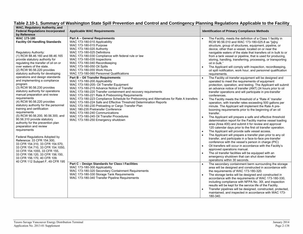
Table 2.10-1 summarizes the regulations promulgated under these statutes that apply to this Facility.
Tesoro Savage Vancouver Energy Distribution Terminal January 2014 Application No. 2013-01 Supplement Page 2-138
Table 2.10-1. Summary of Washington State Spill Prevention and Control and Contingency Planning Regulations Applicable to the Facility WAC, Regulatory Authority, and Federal Regulations Incorporated by Reference
Applicable WAC Requirements Identification of Primary Compliance Methods
WAC 173-180 Facility Oil Handling Standards Regulatory Authority: (1) RCW 88.46.160 and 88.46.165 provide statutory authority for regulating the transfer of oil on or over waters of the state. (2) RCW 90.56.220 provides statutory authority for developing operations and design standards and implementing a compliance program (3) RCW 90.56.230 provides statutory authority for operations manual preparation and review requirements (4) RCW 90.56.220 provides statutory authority for the personnel training and certification requirements (5) RCW 90.56.200, 90.56.300, and 90.56.310 provide statutory authority for the prevention plan preparation and review requirements Federal Regulations Adopted by Reference: 33 CFR 154.300, 33 CFR 154.310, 33 CFR 154.570, 33 CFR 154.710, 33 CFR 154.1050, 33 CFR 154.1055, 33 CFR 155, 33 CFR 156.120, 33 CFR 156.150, 33 CFR 156.170, 40 CFR 109. 40 CFR 112 Subpart F, 49 CFR 195
Part A – General Requirements WAC 173-180-010 Applicability WAC 173-180-015 Purpose WAC 173-180-020 Authority WAC 173-180-025 Definitions WAC 173-180-030 Compliance with federal rule or law WAC 173-180-035 Inspections WAC 173-180-040 Recordkeeping WAC 173-180-050 Oil Spills WAC 173-180-055 Work Hours WAC 173-180-060 Personnel Qualifications
The Facility, meets the definition of a Class 1 facility in RCW 90.56.010 and WAC 173-180-025.8 as “[a]ny structure, group of structures, equipment, pipeline, or device, other than a vessel, located on or near the navigable waters of the state that transfers oil in bulk to or from a tank vessel or pipeline, that is used for producing, storing, handling, transferring, processing, or transporting oil in bulk.”
The Applicant will comply with inspection, recordkeeping, oil spill notification, work hour, and personnel qualification requirements.
Part B – Oil Transfer Requirements WAC 173-180-200 Applicability WAC 173-180-205- Oil Transfer Equipment WAC 173-180-215 Advance Notice of Transfer WAC 173-180-220 Transfer containment and recovery requirements WAC 173-180-221 Rate A Prebooming Requirements WAC 173-180-223 Compliance Schedule for Prebooming and Alternatives for Rate A transfers WAC 173-180-224 Safe and Effective Threshold Determination Reports WAC 173-180-230 Preloading or Cargo Transfer Plan WAC 180-235 Pretransfer Conference WAC 173-180-240 Communications WAC 173-180-245 Oil Transfer Procedures WAC 173-180-250 Emergency shutdown
The Facility oil transfer equipment will be designed and operated to meet the requirements of equipment protection, operation, and testing. The Applicant will submit an advance notice of transfer (ANT) 24 hours prior to oil transfer operations and will participate in pre-transfer conferences.
The Facility meets the threshold of a “Rate A” transfer operation, with transfer rates exceeding 500 gallons per minute. The Applicant will implement the Rate A pre-booming requirements prior to the beginning of an oil transfer.
The Applicant will prepare a safe and effective threshold determination report for the Facility marine vessel loading area (Area 400) and submit it for review and approval 120 calendar days prior to the first oil transfer operation.
The Applicant will provide safe vessel access. The Applicant will prepare a transfer plan prior to any oil
transfer, and participate in a face-to-face pre-transfer conference with the vessel’s person in charge (PIC)
Oil transfers will occur in accordance with the Facility’s approved operations manual.
The oil transfer facilities will be equipped with an emergency shutdown that can shut down transfer operations within 30 seconds.
Part C – Design Standards for Class I Facilities WAC 173-180-300 Applicability WAC 173-180-320 Secondary Containment Requirements WAC 173-180-330 Storage Tank Requirements WAC 173-180-340 Transfer Pipeline Requirements
The secondary containment berm surrounding the storage area will be designed and constructed in accordance with the requirements of WAC 173-180-320.
The storage tanks will be designed and constructed in accordance with the requirements of WAC 173-180-330, including compliance with NFPA No. 30l, and inspection results will be kept for the service life of the Facility.
Transfer pipelines will be designed, constructed, protected, maintained, and inspected in accordance with WAC 173-180-340.
Tesoro Savage Vancouver Energy Distribution Terminal January 2014 Application No. 2013-01 Supplement Page 2-139
WAC, Regulatory Authority, and Federal Regulations Incorporated by Reference
Applicable WAC Requirements Identification of Primary Compliance Methods
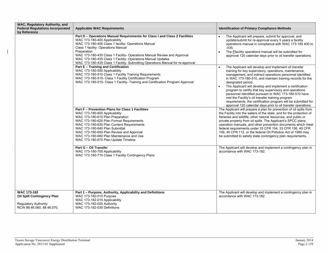
Part D – Operations Manual Requirements for Class I and Class 2 Facilities WAC 173-180-400 Applicability WAC 173-180-405 Class 1 facility- Operations Manual Class 1 facility- Operations Manual Preparation WAC 173-180-430 Class 1 Facility- Operations Manual Review and Approval WAC 173-180-435 Class 1 Facility- Operations Manual Updates WAC 173-180-435 Class 1 Facility- Submitting Operations Manual for re-approval
The Applicant will prepare, submit for approval, and update/submit for re-approval every 5 years a facility operations manual in compliance with WAC 173-180 400 to -435.
The Ffacility operations manual will be submitted for approval 120 calendar days prior to oil transfer operations.
Part E – Training and Certification WAC 173-180-500 Applicability WAC 173-180-510 Class 1 Facility Training Requirements WAC 173-180-515- Class 1 Facility Certification Program WAC 173-180-515- Class 1 Facility- Training and Certification Program Approval
The Applicant will develop and implement oil transfer training for key supervisory, operations, maintenance, management, and indirect operations personnel identified in WAC 173-180-510, and maintain training records for the designated period.
The Applicant will develop and implement a certification program to certify that key supervisory and operations personnel identified pursuant to WAC 173-180-510 have met the Facility’s oil transfer training program requirements; the certification program will be submitted for approval 120 calendar days prior to oil transfer operations.
Part F – Prevention Plans for Class 1 Facilities WAC 173-180-600 Applicability WAC 173-180-610 Plan Preparation WAC 173-180-620 Plan Format Requirements WAC 173-180-630 Plan Content Requirements WAC 173-180-640 Plan Submittal WAC 173-180-650 Plan Review and Approval WAC 173-180-660 Plan Maintenance and Use WAC 173-180-670 Plan Update Timeline
The Applicant will prepare a plan for prevention of oil spills from the Facility into the waters of the state, and for the protection of fisheries and wildlife, other natural resources, and public or private property from oil spills. The Applicant’s SPCC plans, operation manuals, and other prevention documents which meet federal requirements under 33 CFR 154, 33 CFR 156, 40 CFR 109, 40 CFR 112, or the federal Oil Pollution Act of 1990 may be submitted to satisfy state contingency plan requirements.
Part G – Oil Transfer WAC 173-180-700 Applicability WAC 173-180-710 Class 1 Facility Contingency Plans
The Applicant will develop and implement a contingency plan in accordance with WAC 173-182.
WAC 173-182 Oil Spill Contingency Plan Regulatory Authority: RCW 88.46.060, 88.46.070,
Part 1 – Purpose, Authority, Applicability and Definitions WAC 173-182-010 Purpose WAC 173-182-015 Applicability WAC 173-182-020 Authority WAC 173-182-030 Definitions
The Applicant will develop and implement a contingency plan in accordance with WAC 173-182.
Tesoro Savage Vancouver Energy Distribution Terminal January 2014 Application No. 2013-01 Supplement Page 2-140
WAC, Regulatory Authority, and Federal Regulations Incorporated by Reference
Applicable WAC Requirements Identification of Primary Compliance Methods
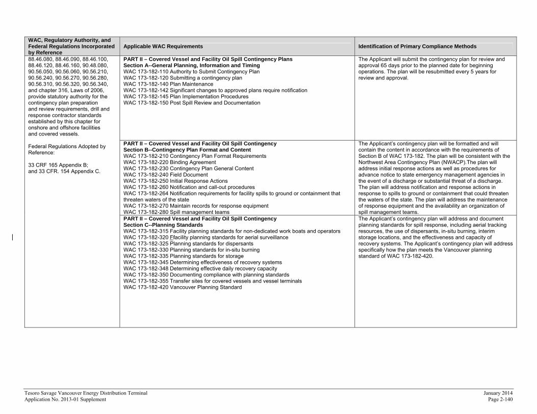
88.46.080, 88.46.090, 88.46.100, 88.46.120, 88.46.160, 90.48.080, 90.56.050, 90.56.060, 90.56.210, 90.56.240, 90.56.270, 90.56.280, 90.56.310, 90.56.320, 90.56.340, and chapter 316, Laws of 2006, provide statutory authority for the contingency plan preparation and review requirements, drill and response contractor standards established by this chapter for onshore and offshore facilities and covered vessels. Federal Regulations Adopted by Reference: 33 CRF 165 Appendix B; and 33 CFR. 154 Appendix C.
PART II – Covered Vessel and Facility Oil Spill Contingency Plans Section A--General Planning, Information and Timing WAC 173-182-110 Authority to Submit Contingency Plan WAC 173-182-120 Submitting a contingency plan WAC 173-182-140 Plan Maintenance WAC 173-182-142 Significant changes to approved plans require notification WAC 173-182-145 Plan Implementation Procedures WAC 173-182-150 Post Spill Review and Documentation
The Applicant will submit the contingency plan for review and approval 65 days prior to the planned date for beginning operations. The plan will be resubmitted every 5 years for review and approval.
PART II – Covered Vessel and Facility Oil Spill Contingency Section B--Contingency Plan Format and Content WAC 173-182-210 Contingency Plan Format Requirements WAC 173-182-220 Binding Agreement WAC 173-182-230 Contingency Plan General Content WAC 173-182-240 Field Document WAC 173-182-250 Initial Response Actions WAC 173-182-260 Notification and call-out procedures WAC 173-182-264 Notification requirements for facility spills to ground or containment that threaten waters of the state WAC 173-182-270 Maintain records for response equipment WAC 173-182-280 Spill management teams
The Applicant’s contingency plan will be formatted and will contain the content in accordance with the requirements of Section B of WAC 173-182. The plan will be consistent with the Northwest Area Contingency Plan (NWACP).The plan will address initial response actions as well as procedures for advance notice to state emergency management agencies in the event of a discharge or substantial threat of a discharge. The plan will address notification and response actions in response to spills to ground or containment that could threaten the waters of the state. The plan will address the maintenance of response equipment and the availability an organization of spill management teams.
PART II – Covered Vessel and Facility Oil Spill Contingency Section C--Planning Standards WAC 173-182-315 Facility planning standards for non-dedicated work boats and operators WAC 173-182-320 Ffacility planning standards for aerial surveillance WAC 173-182-325 Planning standards for dispersants WAC 173-182-330 Planning standards for in-situ burning WAC 173-182-335 Planning standards for storage WAC 173-182-345 Determining effectiveness of recovery systems WAC 173-182-348 Determining effective daily recovery capacity WAC 173-182-350 Documenting compliance with planning standards WAC 173-182-355 Transfer sites for covered vessels and vessel terminals WAC 173-182-420 Vancouver Planning Standard
The Applicant’s contingency plan will address and document planning standards for spill response, including aerial tracking resources, the use of dispersants, in-situ burning, interim storage locations, and the effectiveness and capacity of recovery systems. The Applicant’s contingency plan will address specifically how the plan meets the Vancouver planning standard of WAC 173-182-420.
Tesoro Savage Vancouver Energy Distribution Terminal January 2014 Application No. 2013-01 Supplement Page 2-141
WAC, Regulatory Authority, and Federal Regulations Incorporated by Reference
Applicable WAC Requirements Identification of Primary Compliance Methods
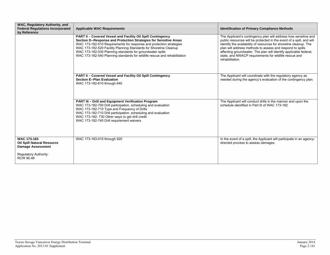
PART II – Covered Vessel and Facility Oil Spill Contingency Section D--Response and Protection Strategies for Sensitive Areas WAC 173-182-510 Requirements for response and protection strategies WAC 173-182-520 Facility Planning Standards for Shoreline Cleanup WAC 173-182-530 Planning standards for groundwater spills WAC 173-182-540 Planning standards for wildlife rescue and rehabilitation
The Applicant’s contingency plan will address how sensitive and public resources will be protected in the event of a spill, and will identify the availability of resources for shoreline cleanup. The plan will address methods to assess and respond to spills affecting groundwater. The plan will identify applicable federal, state, and NWACP requirements for wildlife rescue and rehabilitation.
PART II – Covered Vessel and Facility Oil Spill Contingency Section E--Plan Evaluation WAC 173-182-610 through 640
The Applicant will coordinate with the regulatory agency as needed during the agency’s evaluation of the contingency plan.
PART III – Drill and Equipment Verification Program WAC 173-182-700 Drill participation, scheduling and evaluation WAC 173-182-710 Type and Frequency of Drills WAC 173-182-710 Drill participation, scheduling and evaluation WAC 173-182- 730 Other ways to get drill credit WAC 173-182-740 Drill requirement waivers
The Applicant will conduct drills in the manner and upon the schedule identified in Part III of WAC 173-182.
WAC 173-183 Oil Spill Natural Resource Damage Assessment Regulatory Authority: RCW 90.48
WAC 173-183-010 through 920 In the event of a spill, the Applicant will participate in an agency-directed process to assess damages.
Tesoro Savage Vancouver Energy Distribution Terminal August 2013 Application No. 2013-01 Page 2-142
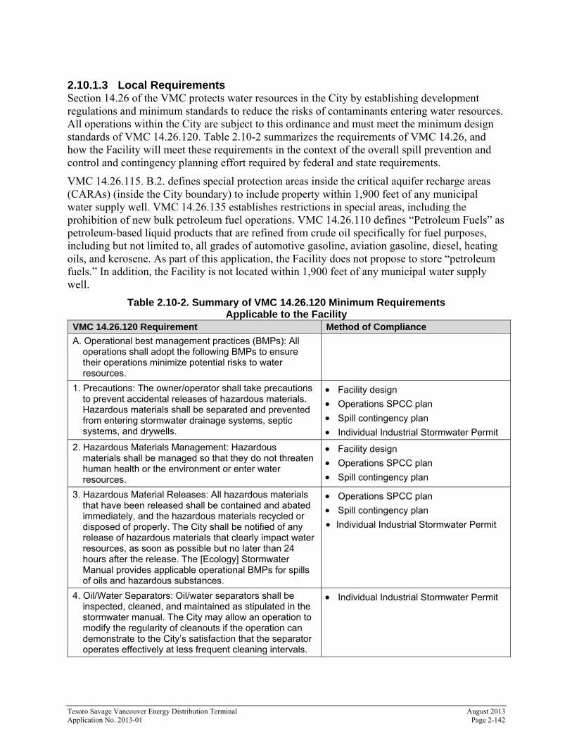
2.10.1.3 Local Requirements Section 14.26 of the VMC protects water resources in the City by establishing development regulations and minimum standards to reduce the risks of contaminants entering water resources. All operations within the City are subject to this ordinance and must meet the minimum design standards of VMC 14.26.120. Table 2.10-2 summarizes the requirements of VMC 14.26, and how the Facility will meet these requirements in the context of the overall spill prevention and control and contingency planning effort required by federal and state requirements.
VMC 14.26.115. B.2. defines special protection areas inside the critical aquifer recharge areas (CARAs) (inside the City boundary) to include property within 1,900 feet of any municipal water supply well. VMC 14.26.135 establishes restrictions in special areas, including the prohibition of new bulk petroleum fuel operations. VMC 14.26.110 defines “Petroleum Fuels” as petroleum-based liquid products that are refined from crude oil specifically for fuel purposes, including but not limited to, all grades of automotive gasoline, aviation gasoline, diesel, heating oils, and kerosene. As part of this application, the Facility does not propose to store “petroleum fuels.” In addition, the Facility is not located within 1,900 feet of any municipal water supply well.
Table 2.10-2. Summary of VMC 14.26.120 Minimum Requirements Applicable to the Facility
VMC 14.26.120 Requirement Method of Compliance
A. Operational best management practices (BMPs): All operations shall adopt the following BMPs to ensure their operations minimize potential risks to water resources.
1. Precautions: The owner/operator shall take precautions to prevent accidental releases of hazardous materials. Hazardous materials shall be separated and prevented from entering stormwater drainage systems, septic systems, and drywells.
Facility design
Operations SPCC plan
Spill contingency plan
Individual Industrial Stormwater Permit
2. Hazardous Materials Management: Hazardous materials shall be managed so that they do not threaten human health or the environment or enter water resources.
Facility design
Operations SPCC plan
Spill contingency plan
3. Hazardous Material Releases: All hazardous materials that have been released shall be contained and abated immediately, and the hazardous materials recycled or disposed of properly. The City shall be notified of any release of hazardous materials that clearly impact water resources, as soon as possible but no later than 24 hours after the release. The [Ecology] Stormwater Manual provides applicable operational BMPs for spills of oils and hazardous substances.
Operations SPCC plan
Spill contingency plan
Individual Industrial Stormwater Permit
4. Oil/Water Separators: Oil/water separators shall be inspected, cleaned, and maintained as stipulated in the stormwater manual. The City may allow an operation to modify the regularity of cleanouts if the operation can demonstrate to the City’s satisfaction that the separator operates effectively at less frequent cleaning intervals.
Individual Industrial Stormwater Permit
Tesoro Savage Vancouver Energy Distribution Terminal January 2014 Application No. 2013-01 Supplement Page 2-143
VMC 14.26.120 Requirement Method of Compliance
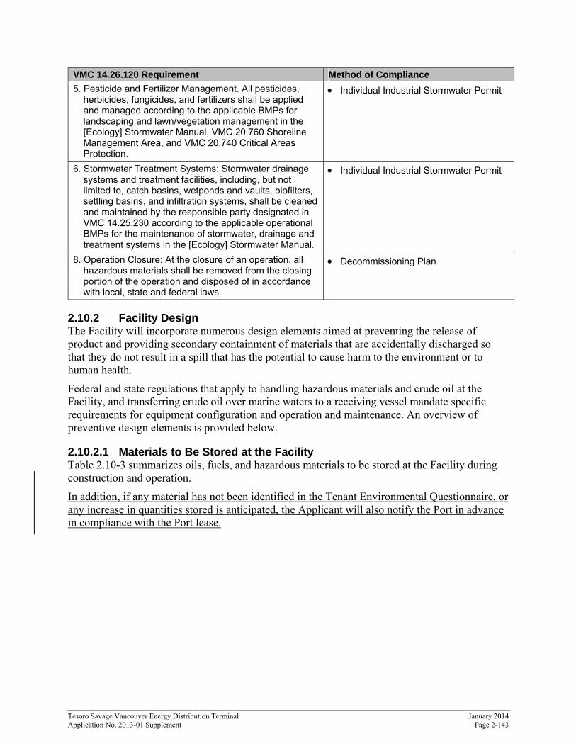
5. Pesticide and Fertilizer Management. All pesticides, herbicides, fungicides, and fertilizers shall be applied and managed according to the applicable BMPs for landscaping and lawn/vegetation management in the [Ecology] Stormwater Manual, VMC 20.760 Shoreline Management Area, and VMC 20.740 Critical Areas Protection.
Individual Industrial Stormwater Permit
6. Stormwater Treatment Systems: Stormwater drainage systems and treatment facilities, including, but not limited to, catch basins, wetponds and vaults, biofilters, settling basins, and infiltration systems, shall be cleaned and maintained by the responsible party designated in VMC 14.25.230 according to the applicable operational BMPs for the maintenance of stormwater, drainage and treatment systems in the [Ecology] Stormwater Manual.
Individual Industrial Stormwater Permit
8. Operation Closure: At the closure of an operation, all hazardous materials shall be removed from the closing portion of the operation and disposed of in accordance with local, state and federal laws.
Decommissioning Plan
2.10.2 Facility Design The Facility will incorporate numerous design elements aimed at preventing the release of product and providing secondary containment of materials that are accidentally discharged so that they do not result in a spill that has the potential to cause harm to the environment or to human health.
Federal and state regulations that apply to handling hazardous materials and crude oil at the Facility, and transferring crude oil over marine waters to a receiving vessel mandate specific requirements for equipment configuration and operation and maintenance. An overview of preventive design elements is provided below.
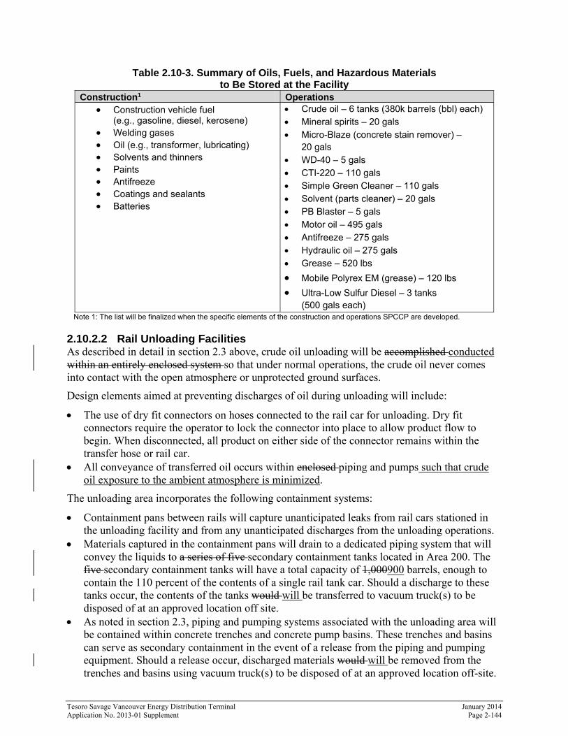
2.10.2.1 Materials to Be Stored at the Facility Table 2.10-3 summarizes oils, fuels, and hazardous materials to be stored at the Facility during construction and operation.
In addition, if any material has not been identified in the Tenant Environmental Questionnaire, or any increase in quantities stored is anticipated, the Applicant will also notify the Port in advance in compliance with the Port lease.
Tesoro Savage Vancouver Energy Distribution Terminal January 2014 Application No. 2013-01 Supplement Page 2-144
Table 2.10-3. Summary of Oils, Fuels, and Hazardous Materials to Be Stored at the Facility
Construction1 Operations Construction vehicle fuel
(e.g., gasoline, diesel, kerosene) Welding gases Oil (e.g., transformer, lubricating) Solvents and thinners Paints Antifreeze Coatings and sealants Batteries
Crude oil – 6 tanks (380k barrels (bbl) each) Mineral spirits – 20 gals Micro-Blaze (concrete stain remover) –
20 gals WD-40 – 5 gals CTI-220 – 110 gals Simple Green Cleaner – 110 gals Solvent (parts cleaner) – 20 gals PB Blaster – 5 gals Motor oil – 495 gals Antifreeze – 275 gals Hydraulic oil – 275 gals Grease – 520 lbs
Mobile Polyrex EM (grease) – 120 lbs Ultra-Low Sulfur Diesel – 3 tanks
(500 gals each) Note 1: The list will be finalized when the specific elements of the construction and operations SPCCP are developed.
2.10.2.2 Rail Unloading Facilities As described in detail in section 2.3 above, crude oil unloading will be accomplished conducted within an entirely enclosed system so that under normal operations, the crude oil never comes into contact with the open atmosphere or unprotected ground surfaces.
Design elements aimed at preventing discharges of oil during unloading will include:
The use of dry fit connectors on hoses connected to the rail car for unloading. Dry fit connectors require the operator to lock the connector into place to allow product flow to begin. When disconnected, all product on either side of the connector remains within the transfer hose or rail car.
All conveyance of transferred oil occurs within enclosed piping and pumps such that crude oil exposure to the ambient atmosphere is minimized.
The unloading area incorporates the following containment systems:
Containment pans between rails will capture unanticipated leaks from rail cars stationed in the unloading facility and from any unanticipated discharges from the unloading operations.
Materials captured in the containment pans will drain to a dedicated piping system that will convey the liquids to a series of five secondary containment tanks located in Area 200. The five secondary containment tanks will have a total capacity of 1,000900 barrels, enough to contain the 110 percent of the contents of a single rail tank car. Should a discharge to these tanks occur, the contents of the tanks would will be transferred to vacuum truck(s) to be disposed of at an approved location off site.
As noted in section 2.3, piping and pumping systems associated with the unloading area will be contained within concrete trenches and concrete pump basins. These trenches and basins can serve as secondary containment in the event of a release from the piping and pumping equipment. Should a release occur, discharged materials would will be removed from the trenches and basins using vacuum truck(s) to be disposed of at an approved location off-site.
Tesoro Savage Vancouver Energy Distribution Terminal January 2014 Application No. 2013-01 Supplement Page 2-145
Ground surfaces between rail tracks in the unloading building will be asphalt or concrete to facilitate material recovery in the event of an unanticipated discharge.
2.10.2.3 Aboveground Storage Tanks Following unloading, crude oil will be conveyed in transfer pipeline to the storage area (Area 300). Design elements aimed at preventing discharges of oil during unloading will include:
As described in section 2.17, the storage tanks will be designed in conformance with applicable industry standards.
The storage tanks will be constructed to meet the NFPA 30 requirements of WAC 173-18-330 and associated manufacturing standards, and will include the necessary measures to prevent tank overfill.
As described in section 2.17, during construction of the tanks industry standard testing techniques will be implemented to ensure the tanks are constructed to the required specifications.
As described in section 2.3.5, cathodic protection of the tank components will be implemented to prevent corrosion.
Hydrostatic testing of the tanks will be conducted to ensure they will meet operational stresses and loads prior to their receiving any crude oil.
Vegetation growth will be controlled within the bermed storage area to prevent vegetation roots from piercing the berm liner. Vegetation control will be accomplished using commercially available herbicides applied in accordance with local, state, and federal regulations.
Design elements related to containing unanticipated discharges will include:
As described in section 2.3.5, the tanks will be constructed with a double tank bottom, with interstitial monitoring to detect leaks should they occur
As described in section 2.3.5, constructing the tanks in a fully lined bermed area with the capacity to contain 110 percent of the largest tank and precipitation from a 24-hour, 100-year storm.
2.10.2.4 Transfer Pipelines and Pumping Systems Crude oil will be conveyed between the unloading area, the storage area, and the vessel marine loading area using a system of transfer pipelines and pumps, as described in section 2.3.4. Design elements aimed at preventing discharges of oil during conveyance will include:
As described in section 2.17, the transfer pipelines will be designed in conformance with applicable industry standards.
All conveyance of crude oil will occur within piping and pumps such that crude oil exposure to the ambient atmosphere is minimized.a fully enclosed system.
Transfer pipelines and the associated pumping systems will be equipped with flow and pressure sensors to identify out of the ordinary operating conditions that could be the result of a pipeline or pump failure and potential risk of crude oil discharge.
Transfer pipelines will be equipped with valves at the exit of and entry to the unloading area, the storage area, and the marine vessel loading area. These valves will include 30-second shut-offs to stop the flow of product should anomalous flow and pressure conditions related to a product spill occur, or in response to operations personnel triggering the shutoff.
Transfer piping will be for the most part installed aboveground to facilitate inspections and maintenance. Where road or rail crossings occur, the piping will be housed in underground
Tesoro Savage Vancouver Energy Distribution Terminal January 2014 Application No. 2013-01 Supplement Page 2-146
steel casings or raised aboveground using standard AREMA clearances (see section 2.3.4, Figure 2.3-9 for an illustration of typical road and rail crossings). Pipelines at each railroad, highway, or road crossing will be designed and installed to adequately withstand the dynamic forces exerted by anticipated traffic or rail loads.
Transfer pipelines will be coated and cathodically protected to prevent corrosion. Sections of transfer pipelines constructed underground will be installed so that they are not in
electrical contact with any metallic structures. This requirement will not preclude the use of electrical bonding to facilitate the application of cathodic protection. Tests will be carried out to determine the presence ofif stray currents are present and protective measures will be taken provided when stray currents are present.
Transfer pipelines will be equipped with leak detection systems meeting regulatory standards.
All pumps will have internal pressure relief systems to avoid overpressure.
Design elements related to containing unanticipated discharges will include:
Piping systems associated with the unloading of crude oil in Area 200 will be placed in concrete trenches; these trenches can serve as secondary containment in the event of a product discharge. Should a discharge occur in the trench, the materials would will be removed by vacuum truck and recycled or disposed off site at an approved location.
Pumps will be located in concrete basins; the concrete basins can serve as secondary containment in the event of a product discharge. Should a discharge occur in the pump basins, the materials would will be removed by vacuum truck and recycled or disposed off site at an approved location.
2.10.2.5 Marine Vessel Loading As described in section 2.3.5, the trestle at Berth 13 will be equipped with piping and hoses to transfer the crude oil from the transfer pipeline system to the receiving marine vessel. In accordance with 33 C.F.R. § 154.530 a facility transferring oil or hazardous materials to or from a vessel with a capacity equal to or greater than 250 barrels, must have fixed catchments, curbing, or other fixed means for small discharge containment of materials at the hose handling and loading arm area, each hose connection manifold area, and under each hose connection that will be coupled or uncoupled as part of the transfer operation. For this Ffacility, it is anticipated that the hose diameter will be between 6 and 12 inches, requiring that discharge containment capacity must be at least three barrels.
At Berth 13, a catchment and sump capable of holding 3 bbl of discharge will be constructed at or below the deck level of sufficient capacity to hold the small discharge containment in addition to stormwater that may fall in the catchment area. The containment will be discharged within one hour of completion of any transfer by pumping into the return line.
In addition the design elements aimed at preventing discharges of oil during conveyance will include:
Hoses and their supporting equipment will be designed to meet the applicable hose protection requirements of WAC 173-180 Part B and 40 33 CFR 156.
All piping located over water will be welded and will not contain any mechanical joints. Vessel mooring systems will meet the applicable requirements of 40 33 CFR 156.
Tesoro Savage Vancouver Energy Distribution Terminal January 2014 Application No. 2013-01 Supplement Page 2-147
2.10.2.6 Booming In accordance with the requirements of WAC 173-180, the Applicant will prepare and implement a booming plan. The purpose of the booming plan is deploy booms in advance of each oil transfer to ensure that any materials accidentally discharge to surface water can be contained.
The Facility will be classified as a “Class I” facility under WAC 173-180-025 (8), that meets “Rate A” oil transfer conditions (i.e., transfers greater than 500 gallons per minute, per WAC 173-180-220 (2)(a). The Facility will, therefore, be required to meet the pre-booming requirements and Rate A alternative measure requirements of WAC 173-180-221. In accordance with these requirements, the Facility will develop and submit for approval a “safe and effective threshold determination report.” This report will identify a Facility-specific booming strategy taking into account ambient conditions (e.g., currents, wind speeds, vessel traffic, etc.) to ensure that transfers are conducted to meet the standards for safe oil transfer operations and meet the zero spill goal (WAC 173-180-010). The Applicant will develop a safe and effective determination report based on final terminal design, and will submit the report for state review and approval 120 calendar days prior to the first oil transfer operation at the Facility as required by WAC 173-180-224 (4).
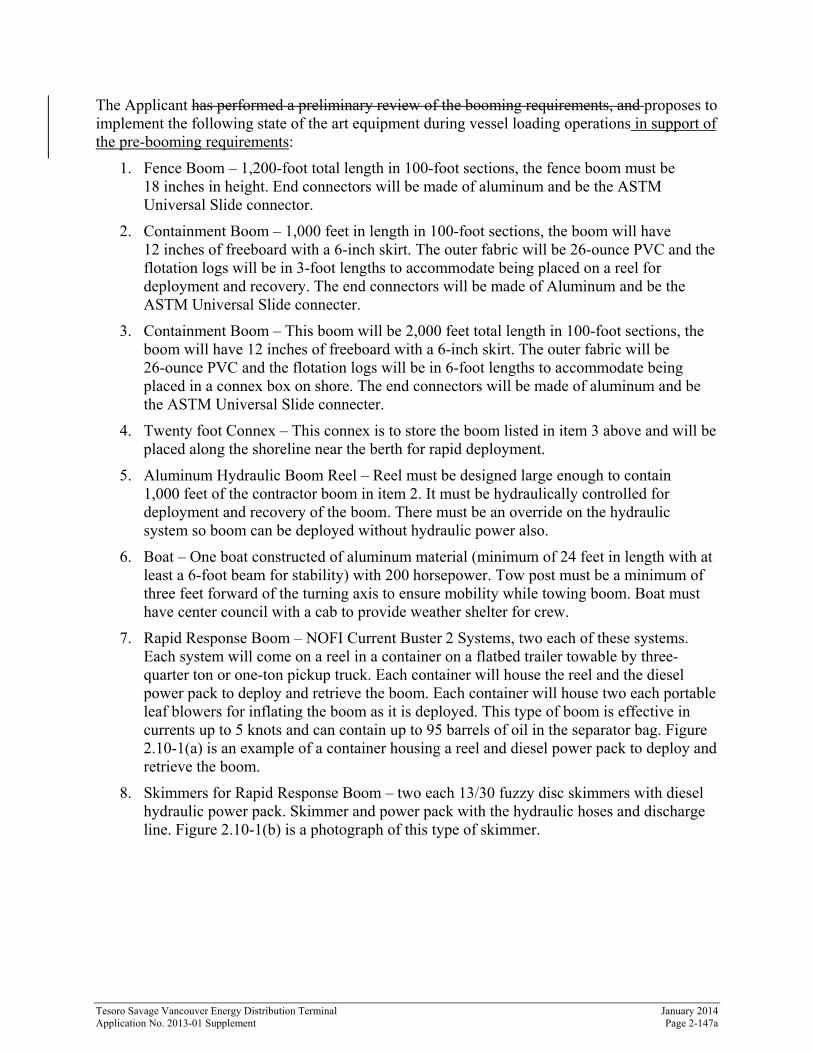
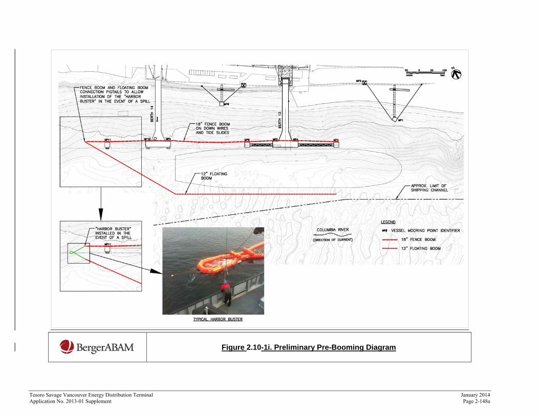
Based on the preliminary design of the Facility as presented in this ASC, and experience with oil transfers at other facilities, the Applicant has performed a preliminary review of booming requirements and anticipates the pre-booming system will consist of a fence boom A fence boom will be placed between the vessel location and the shoreline, and a floating boom . Floating booms will bedeployed after a vessel is at the berth. The floating boom would be and will connected with the fence boom on the downstream and will be open on the upstream offshore side of the moored vessel end due to currents.
Figure 2.10-1i illustrates this conceptual pre-booming configuration. As noted above, the final configuration will be submitted for review to the state. The fence boom would be secured with tide slides and fixed down wires hung from the berth structure. The floating boom would be stored on the berth, and would be deployed using a boom boat. Once in place, the floating boom would be anchored at the upriver end to hold the boom position during the transfer operation. The booming system would be designed with connections for a rapid oil skimmer (also known as a “Harbor Buster”) designed for use in current speeds expected at the facility. The Harbor-Buster would be stowed on the berth, for example on a small aluminum flat-barge with wheels. When needed, it would be launched. The barge would be designed for compatibility with the boat that is used for deploying the floating boom. The boat would maneuver the Harbor Buster-barge into position where the fence- and floating- boom pigtails would be attached to the Harbor Buster and it is then deployed into the water from the barge or would be a stand-alone recovery boom just downstream from the dock.
Tesoro Savage Vancouver Energy Distribution Terminal January 2014 Application No. 2013-01 Supplement Page 2-147a
The Applicant has performed a preliminary review of the booming requirements, and proposes to implement the following state of the art equipment during vessel loading operations in support of the pre-booming requirements:
1. Fence Boom – 1,200-foot total length in 100-foot sections, the fence boom must be 18 inches in height. End connectors will be made of aluminum and be the ASTM Universal Slide connector.
2. Containment Boom – 1,000 feet in length in 100-foot sections, the boom will have 12 inches of freeboard with a 6-inch skirt. The outer fabric will be 26-ounce PVC and the flotation logs will be in 3-foot lengths to accommodate being placed on a reel for deployment and recovery. The end connectors will be made of Aluminum and be the ASTM Universal Slide connecter.
3. Containment Boom – This boom will be 2,000 feet total length in 100-foot sections, the boom will have 12 inches of freeboard with a 6-inch skirt. The outer fabric will be 26-ounce PVC and the flotation logs will be in 6-foot lengths to accommodate being placed in a connex box on shore. The end connectors will be made of aluminum and be the ASTM Universal Slide connecter.
4. Twenty foot Connex – This connex is to store the boom listed in item 3 above and will be placed along the shoreline near the berth for rapid deployment.
5. Aluminum Hydraulic Boom Reel – Reel must be designed large enough to contain 1,000 feet of the contractor boom in item 2. It must be hydraulically controlled for deployment and recovery of the boom. There must be an override on the hydraulic system so boom can be deployed without hydraulic power also.
6. Boat – One boat constructed of aluminum material (minimum of 24 feet in length with at least a 6-foot beam for stability) with 200 horsepower. Tow post must be a minimum of three feet forward of the turning axis to ensure mobility while towing boom. Boat must have center council with a cab to provide weather shelter for crew.
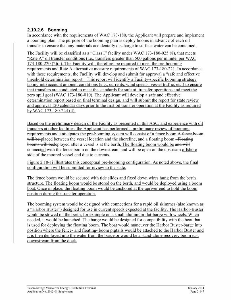
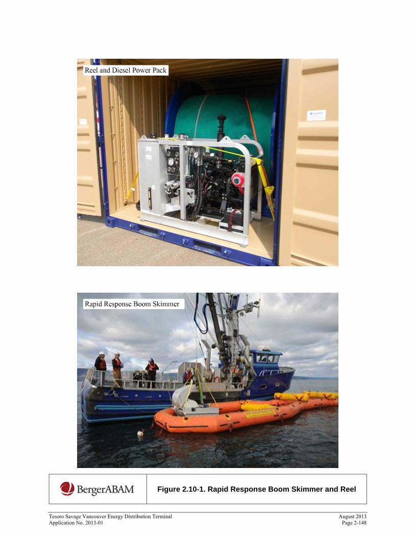
7. Rapid Response Boom – NOFI Current Buster 2 Systems, two each of these systems. Each system will come on a reel in a container on a flatbed trailer towable by three-quarter ton or one-ton pickup truck. Each container will house the reel and the diesel power pack to deploy and retrieve the boom. Each container will house two each portable leaf blowers for inflating the boom as it is deployed. This type of boom is effective in currents up to 5 knots and can contain up to 95 barrels of oil in the separator bag. Figure 2.10-1(a) is an example of a container housing a reel and diesel power pack to deploy and retrieve the boom.
8. Skimmers for Rapid Response Boom – two each 13/30 fuzzy disc skimmers with diesel hydraulic power pack. Skimmer and power pack with the hydraulic hoses and discharge line. Figure 2.10-1(b) is a photograph of this type of skimmer.
Tesoro Savage Vancouver Energy Distribution Terminal August 2013 Application No. 2013-01 Page 2-148
Figure 2.10-1. Rapid Response Boom Skimmer and Reel
Tesoro Savage Vancouver Energy Distribution Terminal January 2014 Application No. 2013-01 Supplement Page 2-148a
Figure 2.10-1i. Preliminary Pre-Booming Diagram
Tesoro Savage Vancouver Energy Distribution Terminal January 2014 Application No. 2013-01 Supplement Page 2-149
2.10.3 Spill Prevention, Control, and Contingency Planning
2.10.3.1 Facility Construction The Applicant will have the overall responsibility for compliance with state and federal environmental regulations during construction. The construction management lead will develop and implement a construction SPCC plan in accordance with 40 CFR 112 for compliance with state and federal environmental regulations. The SPCC plan will be submitted to EFSEC for review and approval prior to beginning construction. The employees of the construction contractor will oversee field activities and coordinate the requirements of the SPCC plan. The contractor will be responsible for inspections, training its employees in spill prevention and control, and, if an incident occurs, for containment and cleanup.
The construction SPCC plan will address responsible personnel, spill reporting, project and site information, pre-existing contamination, potential spill sources, spill prevention and response training, spill report form(s), plan approval, and SPCC plan acknowledgement forms (to be signed by all project personnel).
2.10.3.2 Facility Operations The Applicant will prepare and implement the following plans to comply with state and federal requirements.
An operations SPCC plan, prepared under 40 CFR 112 and WAC 173-180, Part F; a preliminary operations SPCC plan is included as Appendix B.2
A safe and effective threshold determination report, prepared under WAC 173-180-224 A pre-loading transfer plan according to WAC 173-180-230 A facility operations manual in compliance with WAC 173-180 400 to -435 An oil transfer training program in compliance with WAC 173-180, Part E A certification program in compliance with WAC 173-180, Part E A spill contingency plan in compliance with WAC 173-182, 40 CFR 112, Subpart D and
33 CFR 154, Subpart F; a preliminary Oil Spill Contingency Plan is included as Appendix B.3
To comply with this complex regulatory context, the Applicant will prepare coordinated plans to meet all applicable local, state, and federal requirements.