Section 14. Down Woody Materials - nrs.fs.fed.us
37
2.0 Phase 3 Field Guide – Down Woody Materials March, 2004 1 3 3 4 4 4 5 6 6 Section 14. Down Woody Materials 14.0 INTRODUCTION ........................................................................................................................... 14.1 DEFINITION OF DOWN WOODY MATERIALS ........................................................................... 14.2 LOCATING AND ESTABLISHING LINE TRANSECTS ................................................................ 14.2.1 CWD transects ...................................................................................................................... 14.2.2 FWD transects ....................................................................................................................... 14.3 TRANSECT LINE SEGMENTING ....................................................................................................... 14.3.1 SUBPLOT NUMBER ............................................................................................................. 14.3.2 TRANSECT ........................................................................................................................... 14.3.3 CONDITION CLASS NUMBER ............................................................................................. 7 14.3.4 BEGINNING DISTANCE ....................................................................................................... 7 14.3.5 SLOPE PERCENT................................................................................................................. 7 14.3.6 ENDING DISTANCE ............................................................................................................. 7 14.4 Sampling Methods for COARSE WOODY DEBRIS (CWD) ................................................................ 7 14.4.1 Tally Rules for Coarse Woody Debris (CWD) ....................................................................... 7 14.4.2 Marking CWD ...................................................................................................................... 10 14.4.3 Recording Procedures for CWD .......................................................................................... 10 14.4.3.1 SUBPLOT NUMBER .................................................................................................... 10 14.4.3.2 TRANSECT .................................................................................................................. 11 14.4.3.3 CWD SLOPE DISTANCE............................................................................................. 11 14.4.3.4 CWD DECAY CLASS................................................................................................... 11 14.4.3.5 SPECIES ...................................................................................................................... 12 14.4.3.6 Diameters ..................................................................................................................... 13 14.4.3.6.1 DIAMETER AT POINT OF INTERSECTION .................................................... 14 14.4.3.6.2 DIAMETER AT THE SMALL END..................................................................... 14 14.4.3.6.3 DIAMETER AT THE LARGE END .................................................................... 15 14.4.3.7 CWD TOTAL LENGTH................................................................................................. 15 14.4.3.8 IS THE PIECE HOLLOW? ........................................................................................... 15 14.4.3.9 CWD HISTORY ............................................................................................................ 16 14.5 SAMPLING METHODS FOR FINE WOODY DEBRIS (FWD) .......................................................... 16 14.5.1 SUBPLOT NUMBER ........................................................................................................... 17 14.5.2 CONDITION CLASS NUMBER ...........................................................................................18 14.5.3 SMALL FWD COUNT .......................................................................................................... 18 14.5.4 MEDIUM FWD COUNT ....................................................................................................... 18 14.5.5 LARGE FWD COUNT ......................................................................................................... 18 14.5.6 HIGH COUNT REASON...................................................................................................... 18 14.5.7 RESIDUE PILE ON TRANSECT ......................................................................................... 19 14.6 DUFF, LITTER, AND FUELBED DEPTH MEASUREMENTS ........................................................... 19 14.6.1 Definitions ............................................................................................................................ 19 14.6.2 Overview of Measurements ................................................................................................. 20 14.6.2.1 Duff and Litter ................................................................................................................ 20 14.6.2.2 Fuelbed......................................................................................................................... 20 14.6.3 SUBPLOT NUMBER ........................................................................................................... 21 14.6.4 TRANSECT ......................................................................................................................... 21 14.6.5 DUFF, LITTER, AND FUELBED SAMPLE.......................................................................... 21 14.6.6 DUFF DEPTH ......................................................................................................................21 14.6.7 LITTER DEPTH ................................................................................................................... 22 14.6.8 FUELBED DEPTH ............................................................................................................... 22 14.7 FUEL LOADING ON THE MICROPLOT ........................................................................................... 22 14.7.1 SUBPLOT NUMBER ........................................................................................................... 23 14.7.2 LIVE SHRUB PERCENT COVER ....................................................................................... 23 14.7.3 LIVE SHRUB HEIGHT......................................................................................................... 23 14.7.4 DEAD SHRUBS PERCENT COVER .................................................................................. 24 14.7.5 DEAD SHRUB HEIGHT ...................................................................................................... 24
Transcript of Section 14. Down Woody Materials - nrs.fs.fed.us
2.0 Phase 3 Field Guide – Down Woody Materials March, 2004
1
33444566
Section 14. Down Woody Materials 14.0 INTRODUCTION........................................................................................................................... 14.1 DEFINITION OF DOWN WOODY MATERIALS........................................................................... 14.2 LOCATING AND ESTABLISHING LINE TRANSECTS ................................................................
14.2.1 CWD transects ...................................................................................................................... 14.2.2 FWD transects .......................................................................................................................
14.3 TRANSECT LINE SEGMENTING ....................................................................................................... 14.3.1 SUBPLOT NUMBER ............................................................................................................. 14.3.2 TRANSECT ........................................................................................................................... 14.3.3 CONDITION CLASS NUMBER............................................................................................. 7 14.3.4 BEGINNING DISTANCE ....................................................................................................... 7 14.3.5 SLOPE PERCENT................................................................................................................. 7 14.3.6 ENDING DISTANCE ............................................................................................................. 7
14.4 Sampling Methods for COARSE WOODY DEBRIS (CWD) ................................................................ 7 14.4.1 Tally Rules for Coarse Woody Debris (CWD) ....................................................................... 714.4.2 Marking CWD ...................................................................................................................... 10 14.4.3 Recording Procedures for CWD.......................................................................................... 10
14.4.3.1 SUBPLOT NUMBER.................................................................................................... 10 14.4.3.2 TRANSECT .................................................................................................................. 11 14.4.3.3 CWD SLOPE DISTANCE............................................................................................. 11 14.4.3.4 CWD DECAY CLASS................................................................................................... 11 14.4.3.5 SPECIES...................................................................................................................... 12 14.4.3.6 Diameters ..................................................................................................................... 13
14.4.3.6.1 DIAMETER AT POINT OF INTERSECTION .................................................... 14 14.4.3.6.2 DIAMETER AT THE SMALL END..................................................................... 14 14.4.3.6.3 DIAMETER AT THE LARGE END .................................................................... 15
14.4.3.7 CWD TOTAL LENGTH................................................................................................. 15 14.4.3.8 IS THE PIECE HOLLOW? ........................................................................................... 15 14.4.3.9 CWD HISTORY............................................................................................................ 16
14.5 SAMPLING METHODS FOR FINE WOODY DEBRIS (FWD) .......................................................... 16 14.5.1 SUBPLOT NUMBER ........................................................................................................... 17 14.5.2 CONDITION CLASS NUMBER...........................................................................................18 14.5.3 SMALL FWD COUNT.......................................................................................................... 18 14.5.4 MEDIUM FWD COUNT....................................................................................................... 18 14.5.5 LARGE FWD COUNT ......................................................................................................... 18 14.5.6 HIGH COUNT REASON...................................................................................................... 18 14.5.7 RESIDUE PILE ON TRANSECT......................................................................................... 19
14.6 DUFF, LITTER, AND FUELBED DEPTH MEASUREMENTS........................................................... 19 14.6.1 Definitions ............................................................................................................................ 19 14.6.2 Overview of Measurements................................................................................................. 20
14.6.2.1 Duff and Litter ................................................................................................................ 20 14.6.2.2 Fuelbed......................................................................................................................... 20
14.6.3 SUBPLOT NUMBER ........................................................................................................... 21 14.6.4 TRANSECT ......................................................................................................................... 21 14.6.5 DUFF, LITTER, AND FUELBED SAMPLE.......................................................................... 21 14.6.6 DUFF DEPTH......................................................................................................................21 14.6.7 LITTER DEPTH ................................................................................................................... 2 2 14.6.8 FUELBED DEPTH............................................................................................................... 22
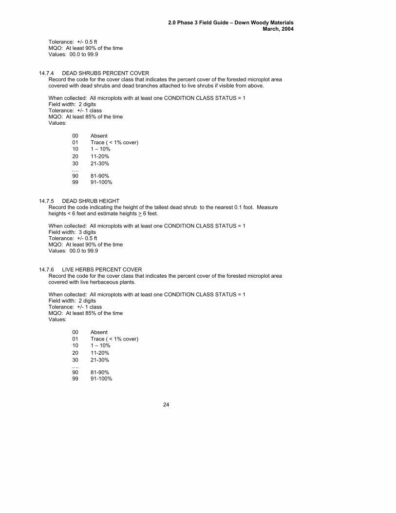
14.7 FUEL LOADING ON THE MICROPLOT ........................................................................................... 22 14.7.1 SUBPLOT NUMBER ........................................................................................................... 23 14.7.2 LIVE SHRUB PERCENT COVER ....................................................................................... 23 14.7.3 LIVE SHRUB HEIGHT......................................................................................................... 23 14.7.4 DEAD SHRUBS PERCENT COVER .................................................................................. 24 14.7.5 DEAD SHRUB HEIGHT ...................................................................................................... 24

2.0 Phase 3 Field Guide – Down Woody Materials March, 2004
2
2414.7.6 LIVE HERBS PERCENT COVER ....................................................................................... 24 14.7.7 LIVE HERBS HEIGHT......................................................................................................... 2514.7.8 DEAD HERBS PERCENT COVER ..................................................................................... 25 14.7.9 DEAD HERBS HEIGHT....................................................................................................... 25 14.7.10 LITTER PERCENT COVER................................................................................................. 25
14.8 SAMPLING RESIDUE PILES ............................................................................................................ 26 14.8.1 SUBPLOT NUMBER ........................................................................................................... 27 14.8.2 CONDITION CLASS............................................................................................................ 27 14.8.3 PILE AZIMUTH.................................................................................................................... 2 7 14.8.4 PILE SHAPE........................................................................................................................ 27 14.8.5 PILE LENGTH 1 .................................................................................................................. 28 14.8.6 PILE LENGTH 2 .................................................................................................................. 28 14.8.7 PILE WIDTH 1 ..................................................................................................................... 28 14.8.8 PILE WIDTH 2 ..................................................................................................................... 28 14.8.9 PILE HEIGHT 1 ................................................................................................................... 2 9 14.8.10 PILE HEIGHT 2.................................................................................................................... 29 14.8.11 PILE DENSITY..................................................................................................................... 29
14.9 ACKNOWLEDGEMENTS................................................................................................................... 29 APPENDIX. DATA SHEETS....................................................................................................................... 30

2.0 Phase 3 Field Guide – Down Woody Materials March, 2004
3
14.0 INTRODUCTION
Down woody materials (DWM) are an important component of forest ecosystems across the country. DWM is dead material on the ground in various stages of decay. Wildlife biologists, ecologists, mycologists, foresters, and fuels specialists are some of the people interested in DWM because it helps describe the:
• Quality and status of wildlife habitats. • Structural diversity within a forest. • Fuel loading and fire behavior. • Carbon sequestration – the amount of carbon tied up in dead wood. • Storage and cycling of nutrients and water – important for site productivity.
Down woody components and fuels estimated by the FIA program are: coarse woody, fine woody, litter, herb/shrubs, slash, duff, and fuelbed depth. Any crew member can learn to collect down woody materials data. If untrained members of the crew are available to help, they can locate, measure, and flag transect lines and record the condition class information for the transect segments. DWM is only sampled in accessible forest conditions intersected by the transect. If a transect crosses a nonforest condition, the boundaries of the condition are recorded (see section 14.3) but no DWM or fuels measurements are taken along this portion of the transect. The majority of DWM in the inventory is sampled using the line intersect sampling method (also called planar intercept method). In this method, transects are established, and individual pieces of CWD or FWD are tallied if the central axis of the piece is intersected by the plane of the transect. In addition, each piece must meet specified dimensions and other criteria before being selected for tally. Special procedures apply when a CWD piece lays across a condition class boundary (section 14.2). Transects will always be used to sample FWD. Transects will be used to sample CWD when crews are able to see and measure individual pieces. The line intersect method is not practical for sampling CWD when it is part of machine-piled windrows or slash piles, or part of log "jumbles" at the bottom of steep-sided ravines. In these situations, individual pieces are impractical to tally separately and are labeled as “residue piles”. A different sampling method is used to tally and measure CWD residue piles (see section 14.8, Sampling Residue Piles).
14.1 DEFINITION OF DOWN WOODY MATERIALS
CWD – In this inventory, CWD includes downed, dead tree and shrub boles, large limbs, and other woody pieces that are severed from their original source of growth and on the ground. CWD also includes dead trees (either self-supported by roots, severed from roots, or uprooted) that are leaning > 45 degrees from vertical. Also included are non-machine processed round wood such as fence posts and cabin logs. For multi-stemmed woodland trees such as juniper, only tally stems that are dead, detached, and on the ground; or dead and leaning > 45 degrees from vertical. CWD does not include:
1. Woody pieces < 3.0 inches in diameter at the point of intersection with the transect. 2. Dead trees leaning 0 to 45 degrees from vertical. 3. Dead shrubs, self-supported by their roots. 4. Trees showing any sign of life. 5. Stumps that are rooted in the ground (i.e., not uprooted). 6. Dead foliage, bark or other non-woody pieces that are not an integral part of a bole or limb. (Bark
attached to a portion of a piece is an integral part). 7. Roots or main bole below the root collar.
FWD – In this inventory, FWD includes downed, dead branches, twigs, and small tree or shrub boles that are not attached to a living or standing dead source. FWD can be connected to a larger branch, as long as this branch is on the ground and not connected to a standing dead or live tree. Only the woody

2.0 Phase 3 Field Guide – Down Woody Materials March, 2004
4
branches, twigs, and fragments that intersect the transect are counted. FWD can be connected to a down, dead tree bole or down, dead shrub. FWD can be twigs from shrubs and vines. FWD must be no higher than 6 feet above the ground to be counted. FWD does not include:
1) Woody pieces > 3.0 inches in diameter at the point of intersection with the transect. 2) Dead branches connected to a live tree or shrub; or to a standing dead tree or dead shrub. 3) Dead foliage (i.e., pine or fir needles, or leaf petioles). 4) Bark fragments or other non-woody pieces that are not an integral part of a branch, twig, or small bole. 5) Small pieces of decomposed wood (i.e., chunks of cubical rot)
14.2 LOCATING AND ESTABLISHING LINE TRANSECTS
Transects are established on each subplot if the subplot center is accessible (i.e., not census water, access denied, or hazardous), and there is at least one forest land condition class mapped within the 24.0-foot radius subplot (CONDITION CLASS STATUS = 1). Transects begin at the subplot center and extend 24.0 feet to the edge of the subplot. The location of condition class boundaries are recorded along the transect. It is extremely important to lay out the transect in a straight line to avoid biasing the selection of pieces and to allow the remeasurement of transect lines and tally pieces for future change detection. Transect lines should be marked with a pin or small piece of flagging at the end of the line (24.0 feet, horizontal distance) to help the QA staff identify the path of the transect during the check-plot procedure. Because the tolerance for the transect azimuth is +/- 2 degrees, the line might have been laid down in a slightly different direction from the check-plot crew. This could affect the location of diameter measurements for CWD pieces as well as identifying whether a CWD piece is a valid tally piece. It is also helpful to mark the point where the FWD transect begins (14 feet, slope distance).
14.2.1 CWD transects Three transects are established that originate at the subplot center and extend out 24.0 feet horizontal distance (the radius of the subplot) at azimuths of 30, 150, 270 degrees (Figure 14-1). This transect configuration was chosen to avoid sampling bias on sloped land, where it is possible that CWD may be oriented in one direction. This configuration of transects should pick up CWD logs that are lying parallel to the slope, perpendicular to the slope, and across slope.
14.2.2 FWD transects One transect is established on each subplot, along the 150 degree azimuth. FWD is tallied within 3 size classes. Because FWD is generally present in higher densities, a shorter transect will pick up an acceptable amount of tally. The transect begins at 14 feet (slope distance) from the subplot center and extends out either 6 or 10 feet (slope distance) depending on the FWD size class, as follows:
Category of FWD
Size Class
Diameter range
Transect length
(slope distance)
Transect location
(slope distance)
Small FWD 1 0 in to 0.24 in 6 feet 14 to 20 feet
Medium FWD 2 0.25 in to 0.9 in 6 feet 14 to 20 feet
Large FWD 3 1.0 in to 2.9 in 10 feet 14 to 24 feet

2.0 Phase 3 Field Guide – Down Woody Materials March, 2004
Note that the FWD transects are slope distance not horizontal distance. The formulas used to estimate biomass from the data contain an adjustment for slope. It is helpful to have a size gauge available until your eye is ‘trained’ to recognize the 3 size classes. Examples include a plastic or cardboard card with 3 notches cut for each size class, or a set of 3 dowels representing each size class.
27
30°
D24sa
Fig
14.3 TRA
Transect condition s are identi lot center oudistancesCWD piecinformatio Starting atransect lirecord, thclass encone condtotal of 24NUMBER On subploacross the
N
430°
150°
0°
30°
150°
270°
30°
150°
270°
150°
270°
3
2
1
t. between sub-plots (2, 3, and 4) and sub-plot center (1): 120 ft at angles (deg.) 0, 120, and 0 respectively; dist. between subplot center and microplot center: 12 ft.; shrubs/herbs
pled on microplot. Duff/litter sampled at 24 ft slope dist. on each CWD transect.
is
m
Transect Information
FWD < 0.25”& 0.26”-0.99”
FWD 1.00”-2.99”
6 ft. s.d.
10 ft. s.d.
24 ft. h.d.
s.d.= slope dist., h.d.=horizontal dist.
Key
Sub-plot
Micro-plotCWD Tran.FWD Tran.
CWD ≥3.00”
ure 14-1. Plot layout for sampling CWD, FWD, and fuels.
NSECT LINE SEGMENTING
lines are segmented to determine the length of transect that occurs within each mapped class intersecting the line. A segment is a length of transect that is in one condition. Segmentfied by recording the BEGINNING DISTANCE and ENDING DISTANCE of the slope from subp
t to the end of the subplot. In the office, the segmenting data will be combined with CWD to determine which condition class each piece falls in (condition classes are not assigned to es in the field). If more than one condition is found on the FWD transects, the segmenting n recorded here will provide the length of transect in each condition.t the subplot center and working towards the fixed radius plot boundary, each segment of ne in a different condition class is delineated and recorded as a separate record. On each e BEGINNING DISTANCE and ENDING DISTANCE of the slope are recorded for each condition ountered. The first record for each transect will have a BEGINNING DISTANCE of 0 feet. If only ition class occurs on the transect line, only one segment is recorded. The transect must extend a .0 feet horizontal distance. If the entire 24.0-foot subplot is nonforest, enter codes for SUBPLOT , TRANSECT, CONDITION CLASS NUMBER, followed by zeros in the remaining fields.
ts where a transect intersects a boundary between condition classes, the transect continues boundary into the adjacent class (Figure 14-2). Although DWM is only sampled in accessible
5

2.0 Phase 3 Field Guide – Down Woody Materials March, 2004
forest conditions, all CONDITION CLASS BOUNDARIES (BEGINNING DISTANCE and ENDING DISTANCE) are recorded on each transect. Individual pieces of DWM intersected by a transect are tallied or counted if they meet the tally rules for CWD or FWD specified in the sections that follow. It is expected that the majority of FWD transects will be in one condition, but if the condition class changes along the transect, a count is recorded for each condition. Again, the segmenting data recorded here will identify which condition class is associated with each count.
O ld g row th
C lea rcu t
S econd g row th
S ap lings
C rop land
H a rdw oo d fo re s t
O ld g row th
Figure 14-2. Transects are installed across condition class boundaries.
14.3.1 SUBPLOT NUMBER Record the code indicating the subplot center from which the transect originates. When collected: All tally segments Field width: 1 digit Tolerance: No errors MQO: At least 99% of the time Values: 1 to 4
1 Center subplot 2 North subplot 3 Southeast subplot 4 Southwest subplot
14.3.2 TRANSECT Record the code indicating the transect on which a condition class is being delineated. The three transects used are 30 degrees, 150 degrees, and 270 degrees. These transects, when being installed, have a tolerance of +/- 2 degrees. When Collected: All tally segments Field width: 3 digits Tolerance: No errors MQO: At least 99% of the time Values:
030 15
Transect extends 30 degrees from subplot center
0 270
Transect extends 150 degrees from subplot center
14.3.3 CONDITION CLASS NUMBER
Transect extends 270 degrees from subplot center
6
2.0 Phase 3 Field Guide – Down Woody Materials March, 2004
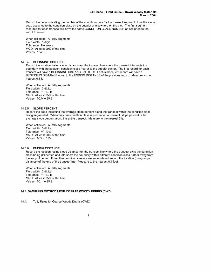
Record the code indicating the number of the condition class for the transect segment. Use the same
7
code assigned to the condition class on the subplot or elsewhere on the plot. The first segment ame CONDITION CLASS NUMBER as assigned to the
git olerance: No errors
14. G DISTANCE ecord the location (using slope distance) on the transect line where the transect intersects the
boundary with the adjacent condition class nearer to the subplot center. The first record for each ISTANCE of 00.0 ft. Each subsequent record will have a
e
olerance: +/- 1.0 ft
14.ecord the code indicating the average slope percent along the transect within the condition class
being segmented. When only one condition class is present on a transect, slope percent is the the entire transect. Measure to the nearest 5%.
olerance: +/- 10%
14. NCE ecord the location (using slope distance) on the transect line where the transect exits the condition
class being delineated and intersects the boundary with a different condition class further away from condition classes are encountered, record the location (using slope
olerance: +/- 1.0 ft
14. DS FOR COARSE WOODY DEBRIS (CWD)
recorded for each transect will have the ssubplot center. When collected: All tally segments Field width: 1 diTMQO: At least 99% of the time Values: 1 to 9
3.4 BEGINNINR
transect will have a BEGINNING DBEGINNING DISTANCE equal to the ENDING DISTANCE of the previous record. Measure to thnearest 0.1 ft. When collected: All tally segments Field width: 3 digitsTMQO: At least 95% of the time Values: 00.0 to 99.9
3.5 SLOPE PERCENT R
average slope percent along When collected: All tally segments Field width: 3 digits TMQO: At least 90% of the time Values: 005 to 155
3.6 ENDING DISTAR
the subplot center. If no other distance) of the end of the transect line. Measure to the nearest 0.1 foot. When collected: All tally segments Field width: 3 digits TMQO: At least 95% of the time Values: 00.1 to 99.9
4 SAMPLING METHO
14.4.1 Tally Rules for Coarse Woody Debris (CWD)
2.0 Phase 3 Field Guide – Down Woody Materials March, 2004
r le forest land conditions only. Tally a piece if its central longitudinal axis intersects the transect, and the condition class is accessible
is condition.
es or Follow
leng
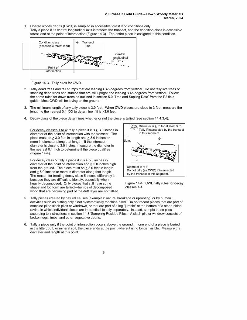
1. Coa se woody debris (CWD) is sampled in accessib
forest land at the point of intersection (Figure 14-3). The entire piece is assigned to th
2. T t are leaning > 45 degrees from vertical. Do not tally live trestan upright and leaning < 45 degrees from vertical.
3.
Figure 14-3. Tally rules for CWD.
longitudinal
Point of intersection
Condition class 1 Transect (accessible forest land)
Central
line
axis
ally dead trees and tall stumps tha
the ection 5.0 ‘Tree and Sapling Data’ from the P2 field guid
The
4. Dec
For
amec
dipimordiamthe (Fig
FordiamfromandThe
5. acti
6. in th
becheashawoo
Tall
macraviaccbrok
Tall
diam
ding dead trees and stumps that are still same rules for down trees as outlined in s
8
easure the th to the nearest 0.1 f00t to determine if it is >
When CWD pieces are close to 3 feet, m
e. Most CWD will be laying on the ground.
minimum length of any tally piece is 3.0 feet. 3.0 feet.
e is tallied (see section 14.4.3.4). ay class of the piece determines whether or not the piec
decay classes 1 to 4: tally a piece if it isDiaT
cay ses meter is > 3” for at least 3.0’.
ally if intersected by the transect in this segment.
> 3.0 inches in eter at the point of intersection with the transect. The
e must be > 3” diam.
3.0 feet in length and > 3.0 inches or e in diameter along that length. If the intersect eter is close to 3.0 inches, measure the diameter to
nearest 0.1 inch to determine if the piece qualifies ure 14-4).
decay class 5: tally a piece if it is > 5.0 inches in eter at the point of intersection and > 5.0 inches high the ground. The piece must be > 3.0 feet in length
> 5.0 inches or more in diameter along that lengt reason for treating decay class 5 pie
h.
d allied.
g) or by human vities such as cutting only if not systematically machine-piled. Do not record pieces that are part of
sided
rs above the ground. If one ene litter, duff, or mineral soil, the piece ends at the point where it is no longer
ces differently is ause they are difficult to identify, especially when vily decomposed. Only pieces that still have some pe and log form are tallied—humps of decomposed that are becoming part of the duff layer are not t
y pieces created by natural causes (examples: natural breakage or uprootin
Diameter is < 3” Do not tally (as CWD) if intersected by the transect in this segment.
Declas
1-4
Figure 14-4. CWD tally rules for decay classes 1-4.
hine-piled slash piles or windrows, or that are part of a log "jumble" at the bottom of a steep-ne in which individual pieces are impractical to tally separately. Instead, sample these piles ording to instructions in section 14.8 ‘Sampling Residue Piles’. A slash pile en logs, limbs, and other vegetative debris.
y a piece only if the point of intersection occu
eter and length at this point.
d of a piece is buried visible. Measure the
or windrow consists of

2.0 Phase 3 Field Guide – Down Woody Materials March, 2004
7. If the central longitudinal axis of a piece is intersected more than once on a transect line or if it is intersected by two transect lines, tally the piece each time it is intersected (uncommon situation, see Figure 14-5).
Tally piece twice
Tally piece twice
Points of intersection
Figure 14-5. CWD tally rules: intersections.
8. Tally a piece only once if the subplot center falls directly on the central longitudinal axis of the piece. Tally the piece on the 30 degree transect and record the CWD Distance as 001.
9. If a piece is fractured across its diameter or length, and would pull apart at the fracture if pulled from either end or sides, treat it as two separate pieces. If judged that it would not pull apart, tally as one piece. Tally only the piece intersected by the transect line.
10. Do not tally a piece if it intersects the transect on the root side of the root collar. Do not tally roots.
11. When the transect crosses a forked down tree bole or large branch connected to a down tree, tally each qualifying piece separately. To be tallied, each individual piece must meet the minimum diameter and length requirements.
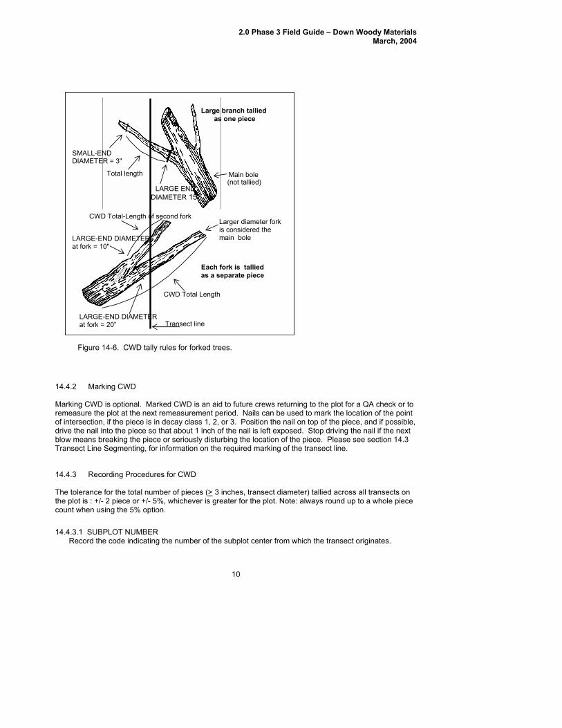
12. In the case of forked trees, consider the "main bole" to be the piece with the largest diameter at the fork. Variables for this fork such as TOTAL LENGTH and DECAY CLASS should pertain to the entire main bole. For smaller forks or branches connected to a main bole (even if the main bole is not a tally piece), variables pertain only to that portion of the piece up to the point where it attaches to the main bole (see Figure 14-6).
13. If a transect intersects a nonforest condition (e.g., a road), no CWD is tallied.
9
2.0 Phase 3 Field Guide – Down Woody Materials March, 2004
(not tallied)Total length Main bole
Large branch tallied as one piece
LARGE END DIAMETER 15”
SMALL-END DIAMETER = 3"
CWD Total-Length of second fork
CWD Total Length
LARGE-END DIAMETER at fork = 10"
LARGE-END DIAMETER at fork = 20” Transect line
Each fork is tallied as a separate piece
Larger diameter fork is considered the main bole
Figure 14-6. CWD tally rules for forked trees.
14.4.2 Marking CWD Marking CWD is optional. Marked CWD is an aid to future crews returning to the plot for a QA check or to remeasure the plot at the next remeasurement period. Nails can be used to mark the location of the point of intersection, if the piece is in decay class 1, 2, or 3. Position the nail on top of the piece, and if possible, drive the nail into the piece so that about 1 inch of the nail is left exposed. Stop driving the nail if the next blow means breaking the piece or seriously disturbing the location of the piece. Please see section 14.3 Transect Line Segmenting, for information on the required marking of the transect line.
14.4.3 Recording Procedures for CWD The tolerance for the total number of pieces (> 3 inches, transect diameter) tallied across all transects on the plot is : +/- 2 piece or +/- 5%, whichever is greater for the plot. Note: always round up to a whole piece count when using the 5% option.
14.4.3.1 SUBPLOT NUMBER Record the code indicating the number of the subplot center from which the transect originates.
10
2.0 Phase 3 Field Guide – Down Woody Materials March, 2004
11
Transect extends 150 degrees from subplot center
14.4.3.3 CWD SLOecord t code indicating the slope distance from the subplot center to the point where the transect tersects the longitudinal center of the piece. If two or more pieces have the same slope distances,
e and record to the nearest 0.1 feet. CWD SLOPE DISTANCE is an
lerance: +/- 1.0 ft
14.icating the decay class of the piece. Code the decay class which
redominates along the recorded CWD TOTAL LENGTH (14.4.3.7) of the piece. Use the guide below ASS.
olerance: +/- 1 class
When collected: All tally pieces Field width: 1 digit Tolerance: No errors MQO: At least 99% of the time Values: 1 to 4
1 Center subplot 2 North subplot 3 Southeast subplot 4 Southwest subplot
14.4.3.2 TRANSECT Record the code indicating the azimuth of the transect on which the piece is sampled. When Collected: All tally pieces Field width: 3 digits Tolerance: No errors MQO: At least 99% of the time Values:
030 15
Transect extends 30 degrees from subplot center
0 270
Transect extends 270 degrees from subplot center
PE DISTANCE Rin
he
record the top piece first. Measurimportant item because it will be used to assign the CWD piece to a condition class by comparing the recorded distance to the piece with the recorded BEGINNING DISTANCE and ENDING DISTANCE tothe condition class boundary. CWD SLOPE DISTANCE is also used to locate the piece for QA and remeasurement in future inventories. When Collected: All tally pieces Field width: 3 digits ToMQO: At least 90% of the time Values: 00.1 to 99.9
4.3.4 CWD DECAY Cecord a 1-digit code ind
LASS Rpto determine CWD DECAY CL When Collected: All tally pieces Field width: 1 digit TMQO: At least 90% of the time Values:

2.0 Phase 3 Field Guide – Down Woody Materials March, 2004
12
y ss
Structural Integrity
Texture of Rotten Portions
Color of Wood
Invading Roots
Branches and Twigs
DecaCla
1 Sound, freshly t logs
Intact, no rot; conks ay
Original color Absent If branches are resent, fine twigs are
fallen, intac of stem dec
absent pstill attached and havetight bark
2 d partly soft
(starting to decay) lled
Original color Absent
one and igs
Sound Mostly intact; sapwoo
but can’t be puapart by hand
If branches are present, many fine twigs are gremaining fine twhave peeling bark
3 Heartwood sound; piece supports its own weight
Reddish- brown or original color
Sapwood only
t Hard, large pieces; sapwood can be pulled apart byhand or sapwood absent
Branch stubs will nopull out
4 tten; piece does not support its own
pe
y
ushed into light brown
Through-out Branch stubs pull out Heartwood ro
weight, but maintains its sha
Soft, small blockpieces; a metal pincan be pheartwood
Reddish or
5 ains its
Red-brown to dark brown
Through-out Branch stubs and pitch pockets have usually rotted down
None, piece no longer maintshape, it spreads out on ground
Soft; powdery when dry
Note: CW SS 5 pieces can be difficult to identify because they often blend into the duff and
r layers. They must still resemble a log, therefore, the first tally rule is that they must be > 5.0 inches in ameter, > 5.0 inches from the surface of the ground, and at least 3.0 feet long. Decomposed logs that
se to describe decay classes for other species
r locations. Concentrate on the structural integrity and texture when estimating a decay class for CWD
DECAY CLASS 2 with a HOLLOW PIECE code of 1. CWD DECAY CLASS 1 should be reserved
r ‘freshly fallen’ logs that are completely intact (i.e., recent windfalls, or harvest).
me as those used in P2 (see Appendix 3 of the P2 field guide). Because CWD includes the tally of large shrub boles and
a code of ‘0001’ for SPECIES if the tally piece is a shrub or vine.
ent), or eartwood smell (particularly if cedars, Douglas-fir, or western hemlock) may provide clues. On
guish r
).
D DECAY CLAlittediare slightly elevated ‘humps’ on the ground are not tallied. CWD DECAY CLASS: The chart above was developed primarily for Douglas-fir in the Pacific Northwest. At the present time, there are no other charts available to uologs. If a log is case hardened (hard, intact outer sapwood shell) but the heartwood is rotten, code this log as aCWD fo
14.4.3.5 SPECIES Record the code indicating the species of the piece. Species codes are the sa
woody vines, enter Species identification may be uncertain for some pieces. The piece's bark (either attached or sloughed and laying beside the piece), branching pattern (if the branches are still preshremeasurement plots, see what tree species were tallied in past inventories. One way to distinhardwoods from softwoods is by the type of decay present. Hardwoods usually have a white ograyish stringy rot, while softwoods usually have a reddish-brown blocky rot. If it is not possible to identify the species, attempt to estimate if it is softwood or hardwood. Enter code 0299 for unknown conifer or 0998 for unknown hardwood. If all else fails, enter the unknown SPECIES code (0999
2.0 Phase 3 Field Guide – Down Woody Materials March, 2004
olerance: No errors
codes in Appendix 3 of the P2 field guide.
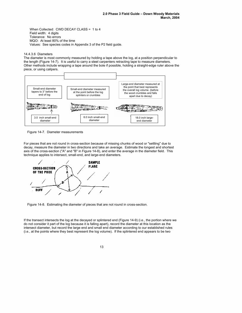
14.The he log, at a position perpendicular to the l ngth (Figure 14-7). It is useful to carry a steel carpenters retracting tape to measure diameters.
wrapping a tape around the bole if possible, holding a straight-edge ruler above the
ecaxis
When Collected: CWD DECAY CLASS = 1 to 4 Field width: 4 digits TMQO: At least 80% of the time Values: See species
4.3.6 Diameters ameter is most commonly measured by holding a tape above t di
eOther methods include piece, or using calipers.
DIAMETER MEASUREMENTS
13
e transect intersects the log at the decayed or sp ed end (Figure 14-9) ot consider it part of the log because it is falling a art), record the diametersect diameter, but record the large end and sma d diameter according
.e., at the points where they best represent the log volume). If the splintered
Figure 14-8. Estimating the diameter of pieces that are not round in cross-se
For pieces that are not round in cross-section because of mis chunks of wood or "settling" due to ay, measure the diameter in two directions and take an average. Estimate the longest and shortest of the cross-section ("A" and "B" in Figure 14-8), and enter average in the dia r field. This
3.0 inch small-end diameter
6.0 inch small-end diameter
18.0 inch large-end diameter
gure 1 meter measurements
Small-end diameter tapers to 3” before the
end of log
Small-end diameter measured at the point before the log
splinters or crumbles
Large-end diameter measured at the point that best represents the overall log volume. (before the wood crumbles and falls
apart due to decay)
Fi 4-7. Dia
singd
the metetechnique applies to intersect, small-end, and large-end diameters.
If th (i.e., the portion where we do n at this location as the inter to our established rules (i end appears to be two
ction.
linterp
ll en
2.0 Phase 3 Field Guide – Down Woody Materials March, 2004
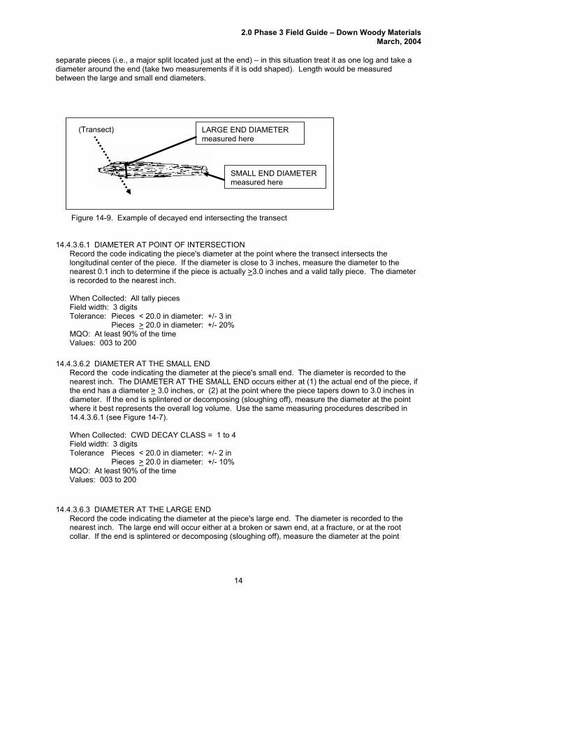
separate pieces (i.e., a major split located just at the end) – in this situation treat it as one log and take a diameter around the end (take two measurements if it is odd shaped). Length would be measured between the large and small end diameters.
14
4.4.3.
ne
6.1 DIAMETER AT POINT OF INTERSECTION e the transect intersects the
longitudinal center of the piece. If the diameter is close to 3 inches, measure the diameter to the arest 0.1 inch to determine if the piece is actually >3.0 inches and a valid tally piece. The diameter
meter: +/- 3 in
measured here
Figure 14-9. Example of decayed end interse t
LARGE END DIAMETER measured here
(Transect)
SMALL END DIAMETER
cting the transec 1
Record the code indicating the piece's diameter at the point wher
is recorded to the nearest inch. When Collected: All tally pieces Field width: 3 digits Tolerance: Pieces < 20.0 in dia Pieces > 20.0 in diameter: +/- 20%
14.iameter at the piece's small end. The diameter is recorded to the
AMETER AT THE SMALL END occurs either at (1) the actual end of the piece, if e end has a diameter >
MQO: At least 90% of the time Values: 003 to 200
4.3.6.2 DIAMETER AT THE SMRecord the code indicating the d
ALL END
nearest inch. The DI 3.0 inches, or (2) at the point where the piece tapers down to 3.0 inches in
posing (sloughing off), measure the diameter at the point
diameter: +/- 2 in Pieces >
thdiameter. If the end is splintered or decomwhere it best represents the overall log volume. Use the same measuring procedures described in 14.4.3.6.1 (see Figure 14-7). When Collected: CWD DECAY CLASS = 1 to 4 Field width: 3 digits Tolerance Pieces < 20.0 in 20.0 in diameter: +/- 10%
14. GE END cating the diameter at the piece's large end. The diameter is recorded to the
earest inch. The large end will occur either at a broken or sawn end, at a fracture, or at the root ollar. If the end is splintered or decomposing (sloughing off), measure the diameter at the point
MQO: At least 90% of the time Values: 003 to 200
4.3.6.3 DIAMETER ARecord the code indi
T THE LAR
nc
2.0 Phase 3 Field Guide – Down Woody Materials March, 2004
ume. Use the same measuring procedures used for
Pieces < 20.0 in diameter: +/- 2 in Pieces >
where it best represents the overall log vol14.4.3.6.1. When Collected: CWD DECAY CLASS = 1 to 4 Field width: 3 digits Tolerance: 20.0 in diameter: +/- 15%
14.cating the total length of the piece. CWD TOTAL LENGTH is the length of the
ece that lies between the piece's recorded DIAMETER AT THE SMALL END AND DIAMETER AT HE LARGE END (14.4.3.6.2 & 14.4.3.6.3). For DECAY CLASS = 5, DIAMETER AT THE SMALL
ARGE END are not recorded for a log, therefore the length is
MQO: At least 90% of the time Values: 003 to 200
4.3.7 CWD TOTAL Lecord the code indi
ENGTH RpiTEND AND DIAMETER AT THE Lmeasured between the two physical ends of the log. For curved logs, measure along the curve. The minimum log length is 3.0 feet before it is a valid tally log. When the length is close to 3.0 feet, measure the length to determine if the piece is actually >3.0 feet. CWD TOTAL LENGTH is recordeto the nearest foot. When Collected: All tally pieces Field width: 3 digits Tolerance: + / - 20
Collected: CWD DECAY CLASS = 1 to 4 idth: 1 digit
At least 90% of the time
before it is classified as a hollow log.
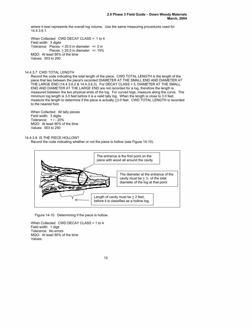
re 14-10. Determining if the piece
d
% QO: At least 90% of the time
14.her or not the piece is hollow (see Figure 14-10).
WhenField wTo
QO:
MValues: 003 to 250
4.3.8 IS THE PIECE HOLLOW? cating whetRecord the code indi
The entrance is the first point on the piece with wood all around the cavity
The diameter at the encavity must be >
trance of the ¼ of the total
diameter of the log at that point
Length of cavity must be > 2 feet,
Figu is hollow.
lerance: No errors MValues:
15
2.0 Phase 3 Field Guide – Down Woody Materials March, 2004
16
nsidered hollow if a cavity extends at least 2 feet along the central ce, and the diameter of the entrance to the cavity is at least
4 of the diameter of the piece where the entrance occurs. The entrance occurs at the point where the circumference of the cavity is whole -- the point where wood is
N
4.4.3.9 Record the code that indicates whether or not the piece of CWD is on the ground as a result of harvesting operations or as a result of natural circumstances. One objective of this item is to identify those pieces that are considered logging residue. If the piece appears to have fallen to the ground as
es such as decomposition or windfall, enter a code of 1. This category would
,
ut y harvesting equipment (bulldozer), enter a
code of 2. A code of 2 would be considered logging residue (usually you are in the middle of a recent
t the log was cut and left on site, then enter a code of “3”.
of “5”.
Field width: 1 digit
MQO: At least 90% of the time
14.5 SA LIN
. Fine Woody Debris (FWD) is sampled in accessible forest land conditions. The length of FWD transects are measured in slope distance--no correction is applied to obtain a horizontal distance.
end for 6.0 or 10.0 feet slope distance. Estimates of FWD biomass calculated in the office, will include a slope correction factor obtained
2.
ce is on the ground as a result of natural causes is on the ground as a result of major recent harvest activity (<= 15 yrs old)
ground as a result of older harvest activity (> 15 yrs old) CWD piece is on the ground as a result of an incidental harvest (such as firewood cutting)
Y A piece is colongitudinal axis of the pie1/
present completely around the circumference of the cavity. The length of the cavity begins at this point. Does not meet criteria for being a hollow log
CWD HISTORY 1
a result of natural causinclude blown out tops, snapped off boles, wind-fallen trees on clearcut edges, and trees that basically collapsed and fell over due to decomposition.
If the piece is on the ground as a result of recent (since last annual remeasurement; if the plot is newthe time between the panel remeasurements) harvesting activity, either because the tree was cdown with a chainsaw (or other device) or pushed over b
clearcut).
If the piece is on the ground as a result of older (more than 15 years) harvesting activity, enter a codeof 3. This would be a situation where you tally an old decomposing log that has a sawn end – if it appears tha
If a piece is on the ground as a result of incidental harvest (such as a standing tree was cut for firewood or small clearing), enter a code of “4”. Incidental harvest involves a few trees and is not apart of a major organized harvesting operation.
If the crew cannot decide the history of the CWD log, classify it as “unknown”, and give it a code
When Collected: CWD DECAY CLASS = 1 to 4
Tolerance: No errors
Values: 1 CWD pie2 CWD piece3 CWD piece is on the
MP G METHODS FOR FINE WOODY DEBRIS (FWD)
5 Exact Reason Unknown 4
1
The FWD transects start at 14.0 feet slope distance and ext
from the transect segmenting data on the subplot.
Only sample FWD that intersects a plane from the ground to a height of 6 feet.

2.0 Phase 3 Field Guide – Down Woody Materials March, 2004
17
3. egree azimuth transect. Two of the FWD size classes (0.01 to 0.24 inches and 0.25 to 0.9 inches) are counted on a 6-foot transect, from 14 to
t transect, from 14 to 24 feet (see section 14.2 for details on transects). These transects overlap. Note: individual
4.
r needles or non-woody parts of a tree or shrub.
ion. Transects that fall on very dense FWD where counting is nearly
impossible, can be subsampled and calculated. For example, an accurate count can be
7.
dicating that this is an unusual situation (see section 14.5.6).
ssume the count is zero in this area, and continue counting if there is transect line beyond the boulder.
9. not
1 in RESIDUE PILE ON TRANSECT which indicates that a residue pile has intersected the transect
10. d
s obtained from the transect segmenting data entered for the subplot.
14.5.1 Rec . When collected: All tally segments
QO: At least 99% of the time
subplot
outheast subplot 4 Southwest subplot
FWD is sampled in three size classes, on the 150 d
20 feet. Pieces in the third size class (1.0 to 2.9 inches) are counted on a 10-foo
diameters are not recorded for FWD.
Count a piece of FWD if it intersects the transect, and the condition class is accessible forest land at the point of intersection. Only count a piece if the twig, branch, wood fragment, or shrub/tree bole are woody. Do not count pine or fi
5. Accumulate the number of pieces counted within each size class and enter the total count on one record for the subplot (unless there are >1 condition classes). If there is no tally on a transect, enter zeros for the count.
6. Accurate counts of FWD can be conducted efficiently up to about 50 pieces for small and medium
size classes, and up to 20 pieces for the large size class. After that, crews can begin estimatingcounts in a systematic fash
conducted on a 2.0-foot section of the transect and then multiplied by 3 to provide an estimate for the 6 foot transect, as long as the crew feels that the remaining transect has a similar density of FWD pieces.
If a transect intersects a large pile of material such as a wood rat’s nest or a recently fallen tree (with many attached fine branches), crews should estimate a count based on #6 above, but also enter a code in
8. If rocks, logs, or other obstructions are present along the transect (14- to 24-foot section) include
any FWD that is present on top of these obstructions in the respective FWD counts. If the obstructions are so large (huge boulder) that the top surface cannot be seen, a
If a residue pile intersects the FWD transect at any point along the 14- to 24-foot section, domeasure FWD on this transect. It is too subjective determining exact boundaries of the pile, and how they relate to the exact point on the transect line. To identify this situation, code
line.
If a transect crosses a condition class boundary, record the CONDITION CLASS NUMBER anenter a count for each condition on separate records. Transect lengths within each condition claswill be
SUBPLOT NUMBER ord the code indicating the subplot center from which the transect originates
Field width: 1 digit Tolerance: No errors MValues: 1 to 4
1 Center 2 North subplot 3 S
2.0 Phase 3 Field Guide – Down Woody Materials March, 2004
18
14.5.2 CO ITI R Record t od ber of the condition class that pertains to the FWD count.
When collected: All tally segments
QO: At least 99% of the time
14.ber of pieces counted in this size class (0.01 to 0.24-inch diameter) along the transect
segment. An accurate count should be conducted up to 50 pieces. If the count exceeds 50, the transect can be subsampled to estimate a total count for the transect segment (see 14.5, #6)
51 to 100 = +/- 25% of the total count for the transect
f the time
14.f pieces counted in this size class (0.25 to 0.9-inch diameter) along the transect
segment. An accurate count should be conducted up to 50 pieces. If the count exceeds 50, the transect can be subsampled to estimate a total count for the transect segment (see 14.5, #6)
QO: At least 90% of the time
14.f pieces counted in this size class (1.0 to 2.9 inch diameter) along the transect
egment. An accurate count should be conducted up to 20 pieces. If the count exceeds 20, the transect can be subsampled to estimate a total count for the transect segment (see section 14.5, #6).
MQO: At least 90% of the time
14.lies to the situation encountered on the transect. Enter a code if any of the
ounts on a transect are greater than 100 pieces.
n the transect >
ND ON CLASS NUMBEhe c e indicating the num
Field width: 1 digit Tolerance: No errors MValues: 1 to 9
5.3 SMALL FWD COUNT Record the num
When collected: On the 150 degree transect in CONDITION CLASS STATUS = 1 Field width: 3 digits Tolerance:0 to 50 = +/- 20% of the total count for the transect 100 + = +/- 50% of the total count for the transect MQO: At least 90% oValues: 000 to 999
5.4 MEDIUM FWD COUNT Record the number o
When collected: On the 150 degree transect in CONDITION CLASS STATUS = 1 Field width: 3 digits Tolerance: +/- 20% of the total count for the transect MValues: 000 to 999
5.5 LARGE FWD COUNT Record the number os
When collected: On the 150 degree transect in CONDITION CLASS STATUS = 1 Field width: 3 digits Tolerance: +/- 20% of the total count for the transect
Values: 000 to 500
5.6 HIGH COUNT REASON Enter a code that appc
When Collected: When any count o 100 Field width: 1 digit
2.0 Phase 3 Field Guide – Down Woody Materials March, 2004
19
alues:
4.5.7 RES E Enter a co ha ther a residue pile intersects the FWD transect segment. The default is always 0; crews will enter a 1 if the situation is encountered on the transect. When Collected: On all FWD transects (between 14 and 24 ft)
d
alues:
14.6 DUFF, L ND FUELBED DEPTH MEASUREMENTS
Dep measurements are sampled in accessible forest land conditions. The depth of the duff layer, litter yer, and overall fuelbed are important components of fire models used to estimate fire behavior, fire
spread, fire effects, and smoke production. These measurements are taken at the 24-foot location on stored with other information about
the condition class on the plot. If a residue pile, log, rock, or other obstruction intersects the transect at the
r of freshly fallen leaves, needles, twigs (< 0.25 inch in diameter), cones, detached bark chunks, dead moss, dead lichens, detached small chunks of rotted wood, dead herbaceous stems, and flower parts (detached and not upright). Litter is the loose plant material found on the
e forest floor. Little decomposition has begun in this layer.
nks of wood that are
till inside a decaying log or log end (i.e., if a decayed log end has a lot of rotten cubes or pieces e
the unrotted sapwood shell). If these rotten chunks have spilled out to the ground and are actually on the ground
D is not unusually high ount is due to an overall high density of FWD across the transect
st located on transect 3 Tree or shrub laying across transect 4 Other reason
Tolerance: No errors MQO: At least 90% of the time V 0 FW
1 High c2 Wood Rat’s ne
1 IDU PILE ON TRANSECT de t t indicates whe
Fiel width: 1 digit Tolerance: No errors MQO: At least 90% of the time V
0 No 1 Yes
ITTER, A
th la
each transect. An average depth will be calculated in the office and
24-ft location, do not measure the duff or litter depth. But, do measure the fuelbed depth if the obstructionis a log or residue pile.
14.6.1 Definitions
1. Litter is the laye
top surface of th
Litter is flash fuel – so think about it as the loose material that is exposed to the air, capable of igniting quickly and carrying a fire across the surface of the forest floor.
Litter does not include bark that is still attached to a down log, or rotten chuslaying on a log surface and exposed to air, they are considered part of the log and not litter – firwould burn differently if it hit a pile of rotten punky wood chips, cradled by
surface, then they would be included in the litter layer.
Litter does not include animal manure.
2.0 Phase 3 Field Guide – Down Woody Materials March, 2004
20
ing
2. ists of decomposing leaves and other organic material.
You should see no recognizable plant parts, the duff layer is usually dark decomposed organic
e mineral soil (A horizon) begins.
is
14. Depth m f a log, rock r other obstruction occurs at the sample location, do not measure duff or litter depth, regardless of what is
on top of the obstruction. However, if the obstruction is a log, proceed with the fuelbed depth estimate.
he DUFF, LITTER, AND FUELBED SAMPLE variable has three options for indicating if duff, litter, and/or
nd the fuelbed) were sampled (i.e., submerged part of plot).
aterial derived from the decomposition of
ant and animal litter (pine straw, leaves, twigs, etc) and deposited on either an organic or a mineral tinguished from the litter layer in that the original organic material has undergone
ufficient decomposition that the source of this material (e.g., individual plant parts) can no longer be
il
is
ampled) ; a value f 99.9 will be entered by the TALLY program for each depth.
e material located at the sample point on e transect. Try to preserve the conditions of this location by walking around this point, so the QA staff
4.6.2.2 Fuelbed
Microplot estimates: As you look down on the microplot, litter is the material that you see coverthe surface area of the 6.8-foot radius plot.
Duff is the layer just below litter. It cons
matter. When moss is present, the top of the duff layer is just below the green portion of the moss. The bottom of this layer is the point wher
3. The fuelbed is the accumulated mass of dead, woody material on the surface of the forest floor. Itbegins at the top of the duff layer, and includes litter, FWD, CWD, and dead woody shrubs. In thdefinition, the fuelbed does not include dead hanging branches from standing trees.
6.2 Overview of Measurements
easurements will be taken at the 24-foot (slope distance) location on each transect. Io
Tfuelbed were measured at each sample location. The default value for this variable is 1, indicating that all three variables were measured (duff, litter, and fuelbed). A value of 0 is entered if duff and litter were not sampled (obstruction), but fuelbed was sampled. A value of 2 is entered if none of the three (duff, litter, a
14.6.2.1 Duff and Litter The duff layer is the organic material layer between the A-horizon (or uppermost soil mineral horizon) andhe litter layer. The duff is a soil layer dominated by organic mtplsurface. This layer is dissidentified. Litter is defined as undecomposed or only partially decomposed organic material that can be readily identified (e.g., plant leaves, twigs, etc.). As a general rule, duff depth should rarely exceed a few inches. Crews should be absolutely sure they are measuring deep duff depths, instead of mineral soil layers or parts of the litter layer. Duff can easily weigh more than 6 times that of litter. If unsure of the bottom of the duff layer, crews should feel the texture of the suspect material in their hand. Rub the sobetween your fingers. Does it crumble (duff) or feel more like modeling clay (mineral). Carefully expose a shallow profile of the forest floor by digging out an area at the sample point using a knife, hatchet, or other tool. Estimate the depth of each layer with a ruler to the nearest 0.1 inch. If therea log, rock, or other obstruction on the surface at the sample point, do not measure the litter or duff depth(record DUFF, LITTER, AND FUELBED SAMPLE = 0 or 2, depending if fuelbed can be so As you dig the hole for this measurement, if you encounter a rock, root, or buried log – stop the depth measurement at this point. The height of the litter should be measured at the top of the loosthwill measure the same height as the original crew.
1
2.0 Phase 3 Field Guide – Down Woody Materials March, 2004
21
tion, do not measure fuelbed depth.
T NUMBER
Tolerance: No errors
4. R SEecord t od imuth of the transect.
When collected
ield width: 3 olerance: No errors
f the time
t center rees from subplot center rees from subplot center
14. BED SAMPLE od as measured.
When co tedField wid dToleranc oMQO: At least
alues:
uelbed is sampled
14.epth of the duff layer to the nearest 0.1 inch.
d: At 24.0 ft on each transect ld wi :
Toleran +MQO: A a
alues: .0
ast subplot
Measure the height of the fuelbed from the top of the duff layer (just below the litter) to the highest piece ofwoody debris found at the transect point. Round to the nearest 0.1 foot. If a rock or other obstruction (other than a log) occurs at the 24.0-foot sample loca
14.6.3 SUBPLORecord the code indicating the number of the subplot center from which the transect originates. When collected: All tally segments Field width: 1 digit
MQO: At least 99% of the timeValues: 1 to 4
1 Center subplot h subplot 2 Nort
3 Southe4 Southwest subplot
1 6.4 TR
FT
AN CT e azhe c e indicating th
: All tally segments digits
MQO: At least 99% oValues:
03 Transect extends 30 degrees from subplo0 15 Transect extends 150 deg
ect extends 270 deg0 27 Trans0
6.5 DUFRecord th
F, LITTER, AND FUELe c e indicating if the depth of the duff and litter layer w
llecth: 1
: At 24.0 ft on each transect igit
e: N errors 99% of the time
V
0 Duff and litter depth not sampled; F1 All sampled: Duff, litter, and fuelbed 2 Nothing sampled; Duff, litter, fuelbed are not sampled
6.6 DUFF DEPTH Record the code indicating the d
hen collecteW Fie dth 3 digits
ce: /- 0.5 inch t le 00
st 90% of the time to 99.9 V

2.0 Phase 3 Field Guide – Down Woody Materials March, 2004
22
14.6.8 FUELBED DEPTH ting the depth of the fuelbed layer, to the nearest 0.1 foot. If the fuelbed depth
14.6.7 LITTER DEPTHRecord the code indicating the depth of the litter layer to the nearest 0.1 inch. When collected: At 24.0 ft on each transect Field width: 3 digits Tolerance: +/- 0.5 inch MQO: At least 90% of the time Values: 00.0 to 99.9
Record the code indicais >0 and < 0.1 foot enter 0.1foot. In this situation finer depth resolution will be obtained from the duff nd litter measurements.
4.0 ft on each transect
the time Values: 00.0 to 99.9
14.
Another component of the total fuel loading on a plot is the biomass of live and dead understory material. The ate the percent cover and height of live and dead shr bs (includes grasses) and litter. Fuel loading is estimated in accessible forest lan roplot. Enter one value for all forested conditions combined. Shr ody stems, including woody vines. Herbs are non-woody herbaceous plants, but also nclude ferns, mosses, lichens, sedges, and grasses. Although many forbs and grasses will die by the end the growing season, an estimate of live and dead biomass on a given date will help fire modelers
uring the year, allowing them to estimate fire danger patterns across the landscape.
ead
clude whole ants that are entirely green (or alive) and the live branches on plants that are a mixture of live and dead
ent cover using the same procedures as live fuels, but include plants that re entirely dead and branches or leaves that are dead but still attached to a live plant. Dead plant
for
a When collected: At 2Field width: 3 digits Tolerance: +/- 20% MQO: At least 90% of
7 FUEL LOADING ON THE MICROPLOT
6.8-foot radius microplot will be used to estimubs, live and dead herd conditions on the mic
ubs are plants with wo i of
predict the phenology of herbaceous material d
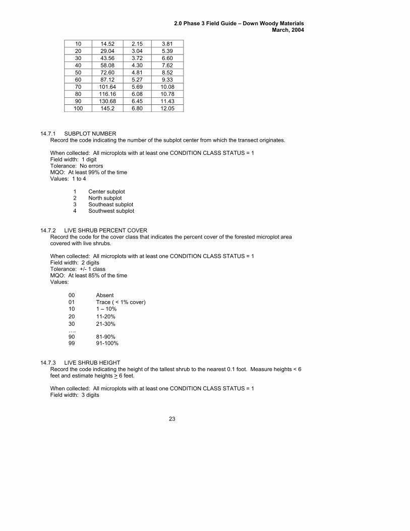
Percent cover is estimated for each of the five fuel categories (live shrubs, dead shrubs, live herbs, dherbs, and litter) in 10-percent classes for the accessible forested conditions of the microplot. For live fuels, estimate the percent of the microplot area that is covered by live plant material. Inplplant parts. Include live branches or leaves that extend into the microplot area from a plant that is actually rooted outside of the microplot. Do not include herbaceous material above 6 feet (i.e., moss, ferns, lichens, epiphytes that are growing in tree branches above 6 feet). For dead fuels, estimate the percamaterial must be clearly visible. Do not include dead material that has fallen to the ground. Cover estimates are made by visualizing an outline around the dead material (with all ‘air’ space included) and accumulating this across the forested microplot area. An estimate of the total height of the shrub and herbaceous layers is also needed to calculate biomass and fuel loadings. Record a height estimate for each fuel category, except litter. Height is estimatedthe tallest shrub on the microplot. Microplot Cover Estimation Guide (Hint: 8.5” x 11” = about 0.5% coverage)
% area (sq ft) radius (ft) square (ft) 1 1.45 0.68 1.20
2.0 Phase 3 Field Guide – Down Woody Materials March, 2004
23
10 14.52 2.15 3.81 20 29.04 3.04 5.39 30 43.56 3.72 6.60 40 58.08 4.30 7.62 50 72.60 4.81 8.52 60 87.12 5.27 9.33 70 101.64 5.69 10.08 80 116.16 6.08 10.78 90 1 30.68 6.45 11.43
100 145.2 6.80 12.05
14.7.1 SUB NURecord th de ind the n of the t center from which the transect originates. When col d: Al ots w least NDITION CLASS STATUS = 1 Field widt digit Tolerance o erroMQO: A t 99% me Values:
1 Center subplot
14. RCENT COVER ass that indicates the percent cover of the forested microplot area
When co ted ith at least one CONDITION CLASS STATUS = 1 Field width: 2 Toleranc -MQO: At least
alues:
20 11-20%
%
14.7.3 L SHRUB T Record code i the tallest shrub to the nearest 0.1 foot. Measure heights < 6 feet an timate
PLOT MBER e co icating umber subplo
lecte l micropl ith at one COh: 1: N rs
tit leas1 to 4
of the
2 North subplot 3 Southeast subplot 4 Southwest subplot
7.2 LIVE SHRUB PERecord the code for the cover cl
e shrubs. covered with liv
llec : All microplots wdigits
e: +/ 1 class 85% of the time
V
00 Absent 01 Trace ( < 1% cover) 10 1 – 10%
30 21-30% …. 90 81-9099 91-100%
IVE HEIGH the ndicating the height ofd es heights > 6 feet.
When c cted: A ots with at least one CONDITION CLASS STATUS = 1 Field w 3 digi
olle ll micropl idth: ts
2.0 Phase 3 Field Guide – Down Woody Materials March, 2004
Toleran
24
+/- 0.5MQO: t 90 e
alues: 00.0 to 99.9
14. that indicates the percent cover of the forested microplot area
overed with dead shrubs and dead branches attached to live shrubs if visible from above.
roplots with at least one CONDITION CLASS STATUS = 1
f the time alues:
20 11-20%
14.7.5 DEA HRRecord th de f the tallest dead shrub to the nearest 0.1 foot. Measure heights < et a te heights >
ce: ft At leas % of the tim
V
7.4 DEAD SHRUBS PERCENT COVER Record the code for the cover classc When collected: All micField width: 2 digits Tolerance: +/- 1 class MQO: At least 85% oV
00 Absent 01 Trace ( < 1% cover) 10 1 – 10%
30 21-30% …. 90 81-90% 99 91-100%
D Se co
UB HEIGHT indicating the height o
6 fe nd estima 6 feet. When col d: lots with at least one CONDITION CLASS STATUS = 1 Field wid digits Tolerance - 0.MQO: At least 9 me
lues: 00.0 to 99.9
14.s the percent cover of the forested microplot area
overed with live herbaceous plants.
roplots with at least one CONDITION CLASS STATUS = 1
f the time alues:
20 11-20%
lecte All micropth: 3: +/ 5 ft
0% of the tiVa
7.6 LIVE HERBS PERCENT COVER Record the code for the cover class that indicatec When collected: All micField width: 2 digits Tolerance: +/- 1 class MQO: At least 85% oV
00 Absent 01 Trace ( < 1% cover) 10 1 – 10%
30 21-30% …. 90 81-90% 99 91-100%

2.0 Phase 3 Field Guide – Down Woody Materials March, 2004
14.
25
LIVE HERBS HEIGHT Record th de the height (at the tallest point) of the live herbaceous layer to the nearest 0.1 foot. mu When col d: lots with at least one CONDITION CLASS STATUS = 1 Field widt digToleranc - 0.MQO: At least 9Values: 0 6.
T COVER
00 Absent
30 21-30%
0% 0%
14. DEAD HERBS HEIGHT Record th de the height (at the tallest point) of the dead herbaceous layer to the nearest 0.1 foot. mu When col d: lots with at least one CONDITION CLASS STATUS = 1 Field widt digToleranc - 0.MQO: At least 9Values: 0 6.
R
on the surface of the forest floor. Decomposition is minimal.
)
7.7e co indicatingMaxi m height is 6 feet.
lecte All microph: 2 its
ft e: +/ 20% of the time
.0 to 0
14.7.8 DEAD HERBS PERCENRecord the code for the cover class that indicates the percent cover of the forested microplot area covered with dead herbaceous plants and dead leaves attached to live plants if visible from above. When collected: All microplots with at least one CONDITION CLASS STATUS = 1 Field width: 2 digits Tolerance: +/- 1 classMQO: At least 85% of the time Values:
01 Trace ( < 1% cover) 10 1 – 10% 20 11-20%
…. 90 81-999 91-10
7.9e co indicatingMaxi m height is 6 feet.
lecte All microph: 2 its
ft e: +/ 20% of the time
.0 to 0
14.7.10 LITTER PERCENT COVERecord the code for the cover class that indicates the percent cover of the forested microplot area covered with litter. Litter is the layer of freshly fallen leaves, twigs, dead moss, dead lichens, and other ne particles of organic matter foundfi
microplots with at least one CONDITION CLASS STATUS = 1 When collected: All
Field width: 2 digits Tolerance: +/- 1 class
of the time MQO: At least 85%alues: V
00 Absent 01 Trace ( < 1% cover
2.0 Phase 3 Field Guide – Down Woody Materials March, 2004
26
0%
14. AMPL E ILES
The line trans et en sampling CWD within piles and windrows. Piles and windrows will be locat mpled on the subplot plot, regardless of whether they intersect a transect.
Piles and win s c ctly by human activity and log piles at the bottom of steep-sided ravines in which individu ec are impossible to tally separately, are more efficiently sampled by using the following instr ns r, loose CWD in piles created by wind throw, landslides, fires, and other natural cause oul using line transects unless it is physically impossible to measure the pieces in the natural pile.
at contains forest land, all of the following criteria must be met
The pile contains pieces of CWD >
10 1 – 10% 20 11-20% 30 21-30% ….
0% 90 81-999 91-10
8 S ING R SIDUE P
ect m hod is not practical whed and sa
drow reated direal pi esuctio . Howeves sh d be tallied
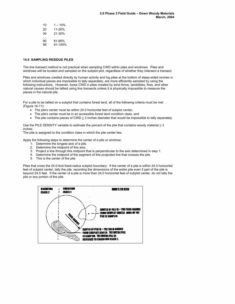
For a pile to be tallied on a subplot th(Figure 14-11):
• The pile's center must be within 24.0 horizontal feet of subplot center, • The pile's center must be in an accessible forest land condition class, and • 3 inches diameter that would be impossible to tally separately.
Use the PILE DENSITY variable to estimate the percent of the pile that contains woody material > 3 inches. The pile is assigned to the condition class in which the pile center lies. Apply the following steps to determine the center of a pile or windrow:
1. Determine the longest axis of a pile.
a line through this midpoint that is perpendicular to the axis determined in step 1. es the pile.
Piles th cross the 24.0-foot fixed-radius subplot boundary: If the center of a pile is within 24.0 horizontal
is 4.0 feet. If the center of a pile is more than 24.0 horizontal feet of subplot center, do not tally the
2. Determine the midpoint of this axis. 3. Project4. Determine the midpoint of the segment of this projected line that cross5. This is the center of the pile.
atfeet of subplot center, tally the pile, recording the dimensions of the entire pile even if part of the pile beyond 2pile or any portion of the pile.

2.0 Phase 3 Field Guide – Down Woody Materials March, 2004
Figure 14-11. esidue pile se
14.8.1 SUBPLOT NUMBER number.
lection examples. R
Record the code indicating the subplot
27
When colleField width: Tolerance: MQO: At leasValues: 1 to
12
14.ss to which the pile is assigned.
rd for all sampled residue piles
Values: 9
4.8.3 PIL ZIRecord the code indicating the azimuth from the subplot center to the pile. This azimuth centers on the
Use 360 for north.
time
14. PILE SHAPE g the shape of the pile. Determine which of the four shapes diagrammed in
cted: Record for all sampled residue piles 1 digit
No errors t 99% of the time
4 Center subplot North subplot
plot plot
3 Southeast sub4 Southwest sub
8.2 CONDITION CLASS Record the code indicating the number of the condition cla When collected: RecoField Width: 1 digit
ors Tolerance: No errMQO: At least 99% of the time
1 to
E A MUTH 1
pile so that it can be relocated.
hen collected: All sampled residue piles WField width: 3 digits Tolerance: +/- 10 MQO: At least 90% of theValues: 001 to 360
8.4Record the code indicatinFigure 14-12 most resembles the pile and record the dimensions. Pile dimensions should be ocularly smoothed out when making estimates. Average the unevenness of protruding pieces. When collected: All sampled residue piles Field width: 1 digit
orsTolerance: No errMQO: At least 90% of the time Values: 1 to 4
2.0 Phase 3 Field Guide – Down Woody Materials March, 2004
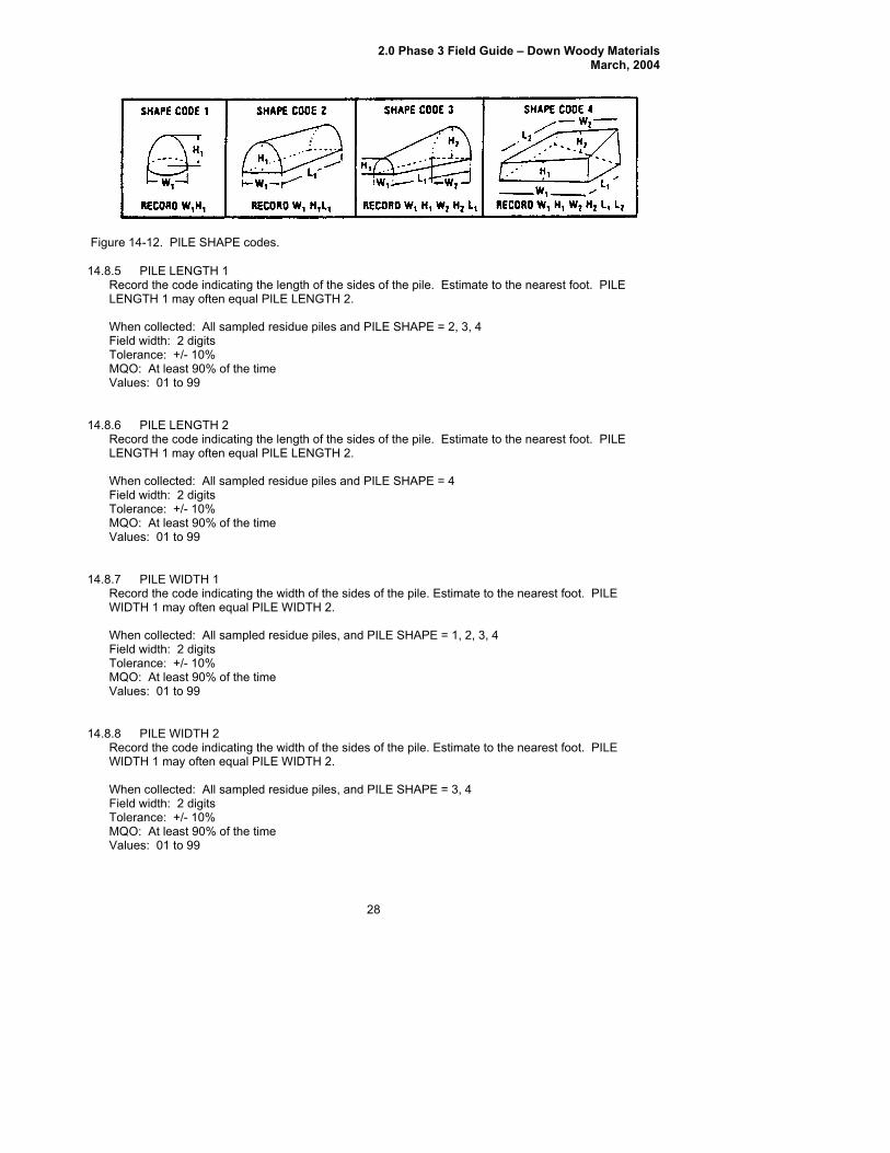
Figure 14-12. PILE SHAPE codes.
14.8.5 RecLENG WhFielToleMQ
14.
E
mpled residue piles and PILE SHAPE = 4
% of the time alues: 01 to 99
14.s of the pile. Estimate to the nearest foot. PILE
IDTH 1 may often equal PILE WIDTH 2.
ampled residue piles, and PILE SHAPE = 1, 2, 3, 4
% of the time Values: 01 to 99
14.s of the pile. Estimate to the nearest foot. PILE
IDTH 1 may often equal PILE WIDTH 2.
ampled residue piles, and PILE SHAPE = 3, 4
% of the time alues: 01 to 99
PILE LENGTH 1 ord the code indicating the length of the sides of the pile. Estimate to the nearest foot. PILE
TH 1 may often equal PILE LENGTH 2.
en collected: All sampled residue piles and PILE SHAPE = 2, 3, 4 d width: 2 digits rance: +/- 10%
O: At least 90% of the time
s of the pile. Estimate to the nearest foot. PILE NGTH 1 may often equal PILE LENGTH 2.
Values: 01 to 99
8.6 PILE LENGTH 2 Record the code indicating the length of the sideL When collected: All saField width: 2 digits Tolerance: +/- 10% MQO: At least 90V
8.7 PILE WIDTH 1 Record the code indicating the width of the sideW When collected: All sField width: 2 digits Tolerance: +/- 10% MQO: At least 90
8.8 PILE WIDTH 2 Record the code indicating the width of the sideW When collected: All sField width: 2 digits Tolerance: +/- 10% MQO: At least 90V
28
2.0 Phase 3 Field Guide – Down Woody Materials March, 2004
29
.
4
14.r end of the pile. Estimate to the nearest foot. PILE
EIGHT 1 may often equal PILE HEIGHT 2.
ampled residue piles, and PILE SHAPE = 3, 4
% of the time alues: 01 to 99
14. pile that consists of wood. Air, soil, rock, plants, etc,
hould be factored out of the estimate. Estimate to the nearest 10 percent.
ampled residue piles
% of the time Values:
00 Absent e ( < 1% cover)
0%
14.9 ACKNO
Contact inform f onal Advisor for this indicator is: Chris
14.8.9 PILE HEIGHT 1 Record the code indicating the height of either end of the pile. Estimate to the nearest foot. PILEHEIGHT 1 may often equal PILE HEIGHT 2 When collected: All sampled residue piles, and PILE SHAPE = 1, 2, 3,Field width: 2 digits Tolerance: +/- 10% MQO: At least 90% of the time Values: 01 to 99
8.10 PILE HEIGHT 2 Record the code indicating the height of eitheH When collected: All sField width: 2 digits Tolerance: +/- 10% MQO: At least 90V
8.11 PILE DENSITY Record the code estimating the percent of thes When collected: All sField width: 2 digits Tolerance: +/- 20% MQO: At least 75
01 Trac10 1 – 10% 20 11-20% 30 21-30% …. 90 81-999 91-100%
WLEDGEMENTS
ation or the Nati Woodall, USDA Forest Service, North Central ea 1992 Folwell Ave, St. Paul, MN 55108, [email protected] Res rch Station, , http:\\ncrs2.fs \ 01\DWM .
.fed.us 48

2.0 Phase 3 Field Guide – Down Woody Materials March, 2004
30
DOWN WOODY MATERIALS – TRANSECT SEGMENT DATA FORM
HEX # ________________ DATE ____/____/____
CWD TRANSECT SEGMENTS SUB PL T CC SLP DIST1
(0.1ft) SLP DIST2
(0.1ft) SLP PCT
HOR DIST (0.1ft)
APPENDIX. DATA SHEETS
xx Xxx x xxx.y xxx.y xxx xxx.y
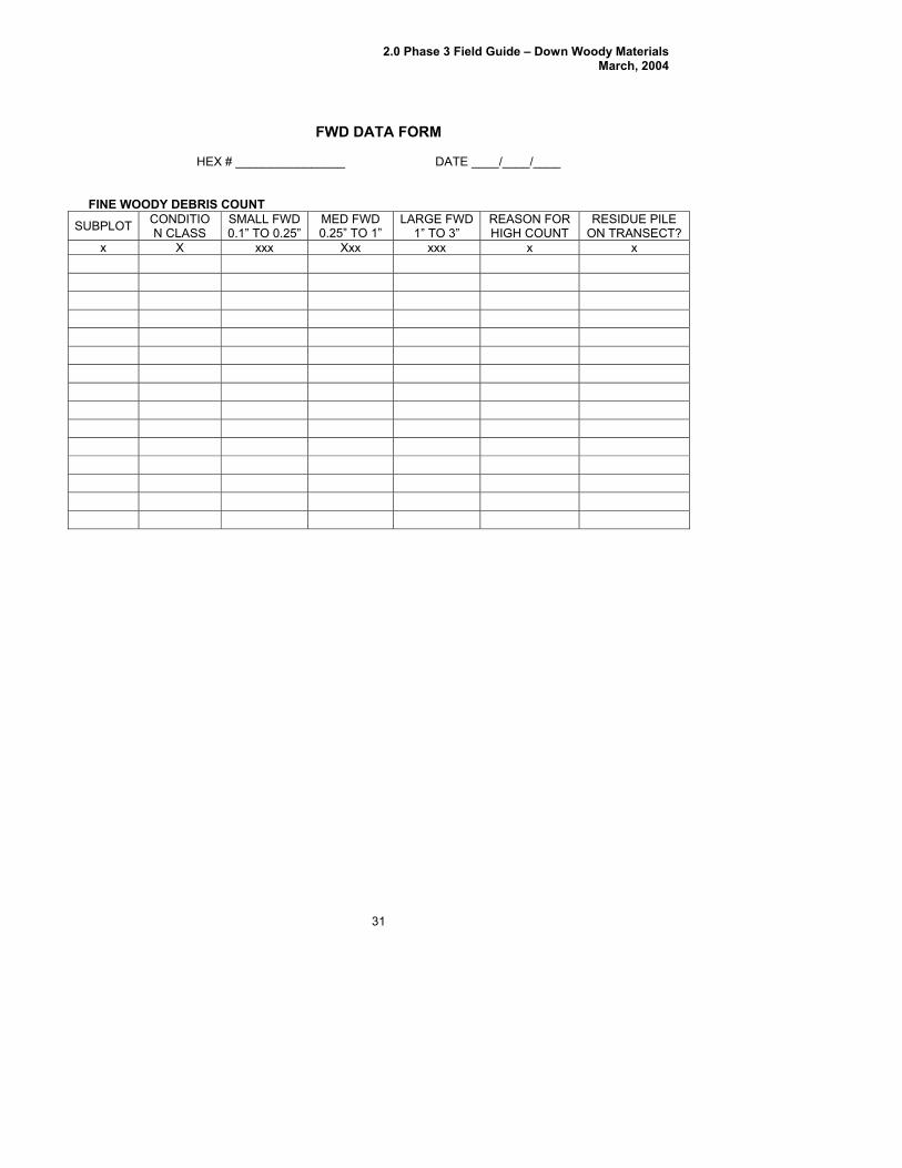
2.0 Phase 3 Field Guide – Down Woody Materials March, 2004
31
HEX # ___ /____
FINE WOODY DEBRIS COUNT SUBPLOT CONDITIO
CLASS SMALL 0.1” TO 0.25” 0.25”
REASON FOR GH NT
RESIDUE PILE CT?
FWD DATA FORM
_____________ DATE ____/____
N FWD MED FWD LARGE FWD
TO 1” 1” TO 3” HI COU ON TRANSEx X xxx Xxx xxx x x

2.0 Phase 3 Field Guide – Down Woody Materials March, 2004
32
COARSE WOODY DEBRIS DATA FORM
HEX # ________________ _ PAGE ____ OF____
SUB CWD TRAN S LRG TOTAL DECAY CWD
DATE _ __/____/____
ML
PLT TRAN
DIST SPC
DIAM DIAM DIAM LENGTH CLASS HOL?
HIST 1 2 3 10 4 5 6 7 8 9 11 x xxx xx xx x.y xxx xxx xxx xxx x x

2.0 Phase 3 Field Guide – Down Woody Materials March, 2004
33
FUELS ASSESSMENT DATA FORM
HEX # ________________ DATE ____/____/____
MICROPLOT FUEL LOADING
S LO
LIVE RU
B %
IVE
B HT
DEAHRB %
AHR
B HT
LIVHE
%
LIH
HT
D
%
DEAD H
HT
LI
UBP
T
SHL
SHRUD DE
S U SD U
E RB
VE ERB H
EAD ERB ERB TTER
%
xx xx.y xx xx.y xx xx.y xx xx.y xx 1 2 2 4
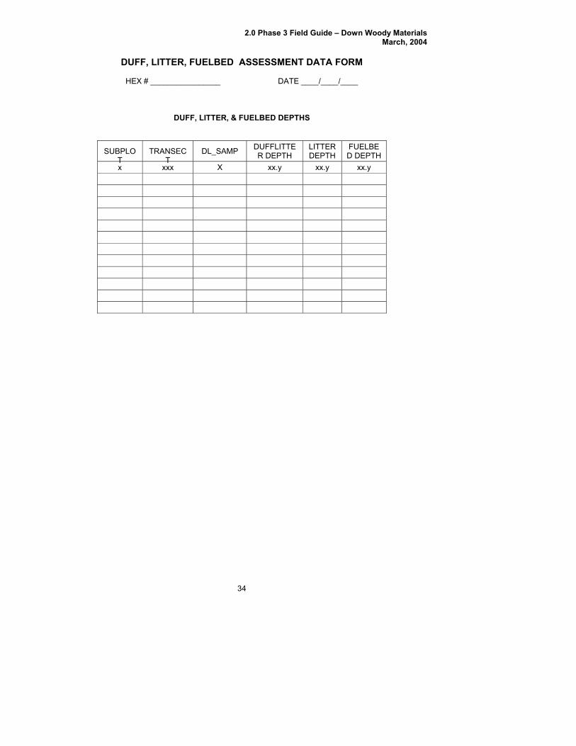
2.0 Phase 3 Field Guide – Down Woody Materials March, 2004
34
DUFF, LI FORM
DU TE E DE
SUBT
TR CT
DL_SAMP D LITTR DEPTH
TTDEPT
FUD DE TH
TTER, FUELBED ASSESSMENT DATA
HEX # ________________ DATE ____/____/____
FF, LIT R, & FU LBED PTHS
PLO
ANSE UFF E LI ER H
ELBEP
x xx X xx.y xx.y xx.y x
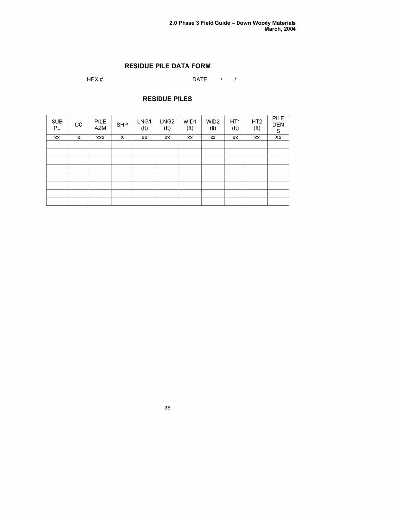
2.0 Phase 3 Field Guide – Down Woody Materials March, 2004
35
RESIDUE PILE DATA FORM
HEX # _____ _/____/____
RESIDUE P
SUB PL CC PILE
AZM HP LNG1(ft)
LNG2 (ft)
WI 1 (
WID2 (ft)
HT1 (ft)
T2 ft)
PILE DEN
S
___________ DATE ___
ILES
S Dft)
H(
xx x xxx X xx xx xx xx xx Xx xx
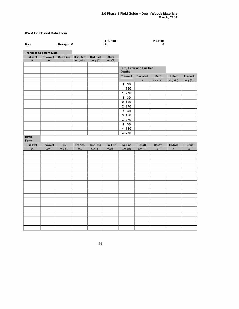
2.0 Phase 3 Field Guide – Down Woody Materials March, 2004
36
DWM Combined Data Form
Date Hexagon # # P-3 Plot
#
FIA Plot
Transect Segment Data
Sub plot Transect Condition Dist Start Dist End Slope xx xxx x xxx.y (ft) xxx.y (ft) xxx (%)
Duff, Litter and Fuelbed D epths
Tra t nsec S ampled Duff Litter Fuelbed x xx.y (in) xx.y (in) xx.y (ft) 1 30 1 1 0 5 1 2 0 7 2 30 2 1 0 5 2 2 0 7 3 30 3 1 0 5 3 2 0 7 4 30 4 150 4 270 CWD Form
Sub Plot Transect Dist Species Tran. Dia Sm. End Lg. End Length Decay Hollow History xx xxx xx.y (ft) xxx xxx (in) xxx (in) xxx (in) xxx (ft) x x x
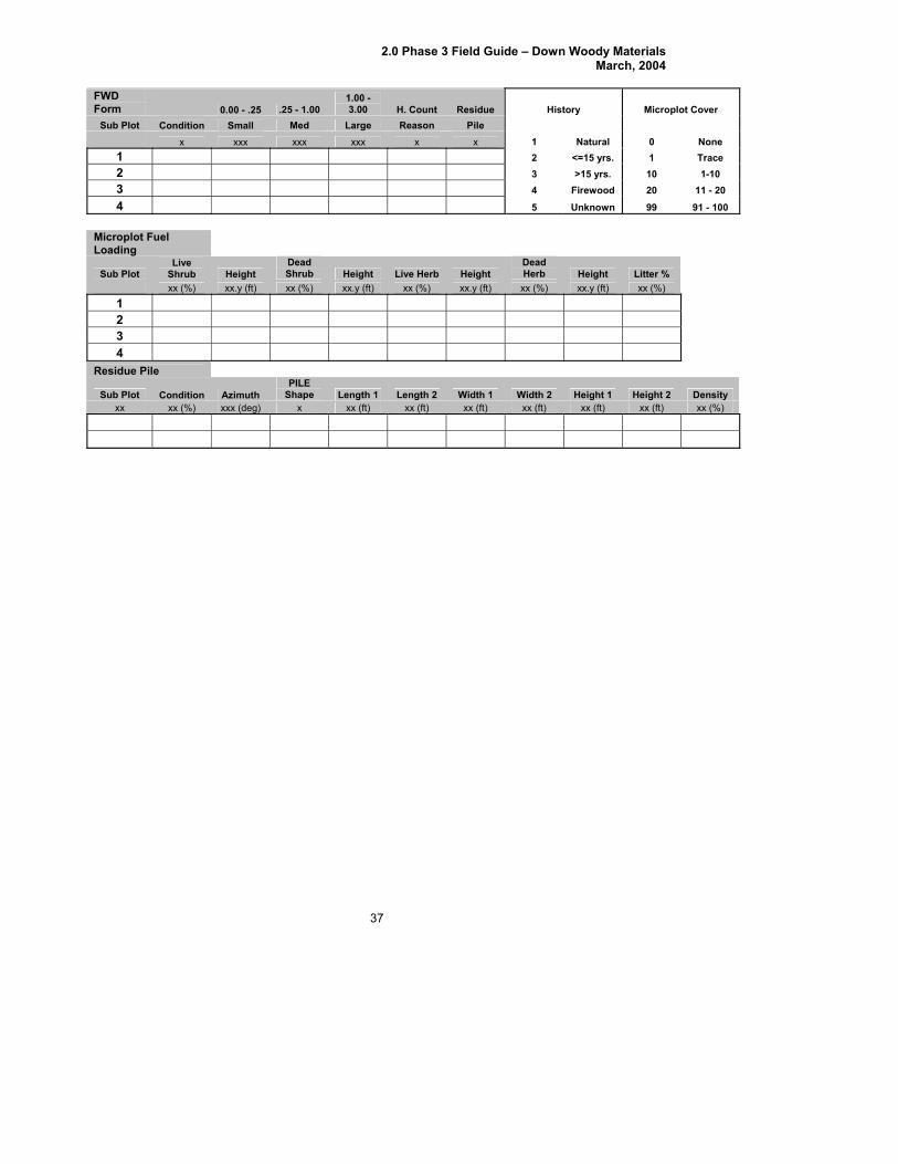
2.0 Phase 3 Field Guide – Down Woody Materials March, 2004
FWD
37
Form 0.00 - .25 .25 - 1.00 1.00 - 3.00 H. Count Residue History Microplot Cover
Sub Plot Condition Small Med Large Reason Pile x xxx xxx xxx x x 1 Natural 0 None 1 2 1 Trace <=15 yrs. 2 3 >15 yrs. 10 1-10 3 4 rewood 20 11 - 20 Fi4 5 Unknown 99 91 - 100
Microplot Fu elLoading
Sub Plot Live
Shrub Height Dead Shrub Height Live Herb Height
Dead Herb Height Litter %
xx (%) xx.y (ft) xx (%) xx.y (ft) xx (%) xx.y (ft) xx (%) xx.y (ft) xx (%) 1 2 3 4
Residue Pile
Sub Plot Condition Azimuth PILE
Shape Length 1 Length 2 Width 1 Width 2 Height 1 Height 2 Density xx xx (%) xxx (deg) x xx (ft) xx (ft) xx (ft) xx (ft) xx (ft) xx (ft) xx (%)