Executive Assessment Math Review Section 1.0, “Arithmetic ...

City of Puyallup - City Standards Section 1 Revised 06/06/11 1-1
SECTION 1.0 ENGINEERING SERVICES PLAN REVIEW PROCESS
The Engineering Services plan review process is independent of the review processes of all other City departments. Therefore, plans or other materials requiring engineering review and approval shall be submitted directly to Engineering Services. The remainder of this section describes the process and the minimum requirements for submittals.
1.1 Predesign Meeting
Applicants are encouraged to meet with the Engineering Services Staff prior to final design and plan submittal. All plans submitted to Engineering Services will receive a preliminary review to make sure that they adequately address the minimum requirements of this manual and all applicable development requirements. Any such plans not meeting these requirements will be returned to the applicant or his designated contact person as unacceptable for review.
1.2 Plan Review Fees
Engineering plan review fees are required separate from other department review fees. The plan review fee shall be paid at the time of submittal. The review process begins when payment of the plan review fee has been made. The permit fee shall be paid prior to the issuance of the permit.
1.3 Plan Checklists
The Engineering Service’s “Plan Review Checklists” are included in this publication (Appendix A) as a guide to help the engineer in the plan preparation process. The City recommends that these checklists be used by the engineer to help facilitate the plan review process.
1.4 Plan Approval
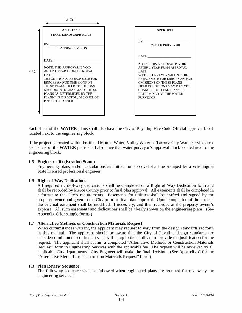
Each sheet of the plans shall have the City of Puyallup approval block located within or adjacent to the design engineer's title block. The approval block shall be as shown below. The plans shall be considered approved by the City when the approval block on each sheet has been signed by the Engineering Services Staff.
2 ¼ ˝ APPROVED
BY _____________________________
CITY OF PUYALLUP ENGINEERING SERVICES
DATE ___________________________
NOTE: THIS APPROVAL IS VOID AFTER 1 YEAR FROM APPROVAL DATE. THE CITY WILL NOT BE RESPONSIBLE FOR ERRORS AND/OR OMISSIONS ON THESE PLANS. FIELD CONDITIONS MAY DICTATE CHANGES TO THESE PLANS AS DETERMINED BY THE ENGINEERING SERVICES MANAGER.
FIRE HYDRANT/FDC LOCATION/ACCESS APPROVED
BY ____________________________
CITY OF PUYALLUP FIRE CODE OFFICIAL
DATE _________________________ NOTE: THIS APPROVAL IS VOID AFTER 1 YEAR FROM APPROVAL DATE. THE CITY WILL NOT BE RESPONSIBLE FOR ERRORS AND/OR OMISSIONS ON THESE PLANS. FIELD CONDITIONS MAY DICTATE CHANGES TO THESE PLANS AS DETERMINED BY THE FIRE CODE OFFICIAL.
3 ¼˝
City of Puyallup - City Standards Section 1 Revised 10/04/16 1-4
2 ¼ ˝
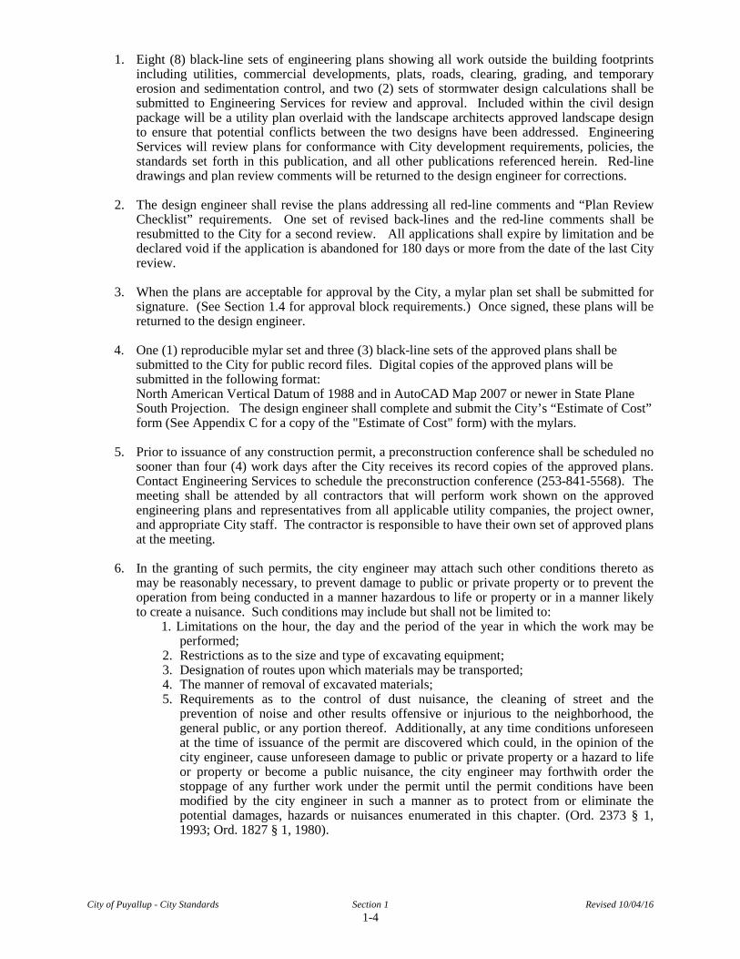
3 ¼ ˝ Each sheet of the WATER plans shall also have the City of Puyallup Fire Code Official approval block located next to the engineering block. If the project is located within Fruitland Mutual Water, Valley Water or Tacoma City Water service area, each sheet of the WATER plans shall also have that water purveyor’s approval block located next to the engineering block. 1.5 Engineer's Registration Stamp
Engineering plans and/or calculations submitted for approval shall be stamped by a Washington State licensed professional engineer.
1.6 Right-of-Way Dedications
All required right-of-way dedications shall be completed on a Right of Way Dedication form and shall be recorded by Pierce County prior to final plan approval. All easements shall be completed in a format to the City’s requirements. Easements for utilities shall be drafted and signed by the property owner and given to the City prior to final plan approval. Upon completion of the project, the original easement shall be modified, if necessary, and then recorded at the property owner’s expense. All such easements and dedications shall be clearly shown on the engineering plans. (See Appendix C for sample forms.)
1.7 Alternative Methods or Construction Materials Request
When circumstances warrant, the applicant may request to vary from the design standards set forth in this manual. The applicant should be aware that the City of Puyallup design standards are considered minimum requirements. It will be up to the applicant to provide the justification for the request. The applicant shall submit a completed “Alternative Methods or Construction Materials Request” form to Engineering Services with the applicable fee. The request will be reviewed by all applicable City departments. City Engineer will make the final decision. (See Appendix C for the “Alternative Methods or Construction Materials Request” form.)
1.8 Plan Review Sequence
The following sequence shall be followed when engineered plans are required for review by the engineering services:
APPROVED FINAL LANDSCAPE PLAN
BY: PLANNING DIVISION
DATE:
NOTE: THIS APPROVAL IS VOID AFTER 1 YEAR FROM APPROVAL DATE. THE CITY IS NOT RESPONSIBLE FOR ERRORS AND/OR OMISSIONS ON THESE PLANS. FIELD CONDITIONS MAY DICTATE CHANGES TO THESE PLANS AS DETERMINED BY THE PLANNING DIRECTOR, DESIGNEE OR PROJECT PLANNER.
APPROVED BY _____________________________
WATER PURVEYOR DATE ___________________________ NOTE: THIS APPROVAL IS VOID AFTER 1 YEAR FROM APPROVAL DATE. WATER PURVEYOR WILL NOT BE RESPONSIBLE FOR ERRORS AND/OR OMISSIONS ON THESE PLANS. FIELD CONDITIONS MAY DICTATE CHANGES TO THESE PLANS AS DETERMINED BY THE WATER PURVEYOR.
City of Puyallup - City Standards Section 1 Revised 10/04/16 1-4
1. Eight (8) black-line sets of engineering plans showing all work outside the building footprints including utilities, commercial developments, plats, roads, clearing, grading, and temporary erosion and sedimentation control, and two (2) sets of stormwater design calculations shall be submitted to Engineering Services for review and approval. Included within the civil design package will be a utility plan overlaid with the landscape architects approved landscape design to ensure that potential conflicts between the two designs have been addressed. Engineering Services will review plans for conformance with City development requirements, policies, the standards set forth in this publication, and all other publications referenced herein. Red-line drawings and plan review comments will be returned to the design engineer for corrections.
2. The design engineer shall revise the plans addressing all red-line comments and “Plan Review
Checklist” requirements. One set of revised back-lines and the red-line comments shall be resubmitted to the City for a second review. All applications shall expire by limitation and be declared void if the application is abandoned for 180 days or more from the date of the last City review.
3. When the plans are acceptable for approval by the City, a mylar plan set shall be submitted for
signature. (See Section 1.4 for approval block requirements.) Once signed, these plans will be returned to the design engineer.
4. One (1) reproducible mylar set and three (3) black-line sets of the approved plans shall be
submitted to the City for public record files. Digital copies of the approved plans will be submitted in the following format: North American Vertical Datum of 1988 and in AutoCAD Map 2007 or newer in State Plane South Projection. The design engineer shall complete and submit the City’s “Estimate of Cost” form (See Appendix C for a copy of the "Estimate of Cost" form) with the mylars.
5. Prior to issuance of any construction permit, a preconstruction conference shall be scheduled no
sooner than four (4) work days after the City receives its record copies of the approved plans. Contact Engineering Services to schedule the preconstruction conference (253-841-5568). The meeting shall be attended by all contractors that will perform work shown on the approved engineering plans and representatives from all applicable utility companies, the project owner, and appropriate City staff. The contractor is responsible to have their own set of approved plans at the meeting.
6. In the granting of such permits, the city engineer may attach such other conditions thereto as
may be reasonably necessary, to prevent damage to public or private property or to prevent the operation from being conducted in a manner hazardous to life or property or in a manner likely to create a nuisance. Such conditions may include but shall not be limited to:
1. Limitations on the hour, the day and the period of the year in which the work may be performed;
2. Restrictions as to the size and type of excavating equipment; 3. Designation of routes upon which materials may be transported; 4. The manner of removal of excavated materials; 5. Requirements as to the control of dust nuisance, the cleaning of street and the
prevention of noise and other results offensive or injurious to the neighborhood, the general public, or any portion thereof. Additionally, at any time conditions unforeseen at the time of issuance of the permit are discovered which could, in the opinion of the city engineer, cause unforeseen damage to public or private property or a hazard to life or property or become a public nuisance, the city engineer may forthwith order the stoppage of any further work under the permit until the permit conditions have been modified by the city engineer in such a manner as to protect from or eliminate the potential damages, hazards or nuisances enumerated in this chapter. (Ord. 2373 § 1, 1993; Ord. 1827 § 1, 1980).

City of Puyallup - City Standards Section 1 Revised 10/04/16 1-4
7. Any changes to the scope of the work as outlined on the approved plans shall be documented on the “Plan Change Request” form provided by the City. The Engineering Services Staff shall review and make recommendations on all proposed changes to the City Engineer for final approval of all changes prior to commencing any work related to the change. (See Appendix C for the “Plan Change Request” form.)
8. Expiration of applications, approvals or permits.
1. Expiration of application. Project applications that are subject to SEPA review shall be governed by applicable SEPA deadlines. All other applications shall expire by limitation if no permit or approval is issued within 180 days after the City determines that the application is complete, unless the City determines that a project proponent has pursued issuance of a permit or approval in good faith. The City may extend the time of action on the application for one or more periods, each period not exceeding 90 days, upon written request by the applicant showing good cause. If an application has expired, plans and other data previously submitted for review may thereafter be returned to the applicant, except that the City shall retain originals or copies in order to comply with applicable record retention laws. In order to renew action on an expired application, the applicant shall resubmit plans and pay a new review or application fee.
2. Expiration of permits or approvals. All permits or approvals shall expire by limitation
and become void if:
a. Work authorized by the permit or approval is not commenced within 180 days of approval or permit issuance;
b. Work is suspended or abandoned for 180 days or more after work is commenced; or
c. After two years from the date of permit or approval issuance, regardless of whether work is finished.
The building official is authorized to grant one or more extensions of time for periods not more than 180 days each. The extensions shall be requested in writing and justifiable cause demonstrated. If a permit or approval expires, the City may issue a new permit or approval for the unfinished work upon a showing of good cause and payment by the project proponent of half of the original permit or approval fee. However, if any applicable law, regulation or rule has materially changed after the expiration of the permit or approval, the City shall have full discretion to decline to issue a new permit even upon a showing of good cause. The option for approval or permit renewal shall lapse two years after the permit or approval expires.
3. This section shall apply to permits and approvals issued under PMC Titles 11, 14 and 21, and applications for such permits or approvals. (PMC 17.42035)
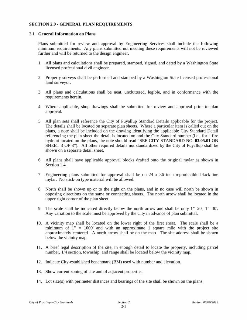
SECTION 2.0 - GENERAL PLAN REQUIREMENTS
2.1 General Information on Plans
Plans submitted for review and approval by Engineering Services shall include the following minimum requirements. Any plans submitted not meeting these requirements will not be reviewed further and will be returned to the design engineer.
1. All plans and calculations shall be prepared, stamped, signed, and dated by a Washington State
licensed professional civil engineer.
2. Property surveys shall be performed and stamped by a Washington State licensed professional land surveyor.
3. All plans and calculations shall be neat, uncluttered, legible, and in conformance with the
requirements herein. 4. Where applicable, shop drawings shall be submitted for review and approval prior to plan
approval. 5. All plan sets shall reference the City of Puyallup Standard Details applicable for the project.
The details shall be located on separate plan sheets. Where a particular item is called out on the plans, a note shall be included on the drawing identifying the applicable City Standard Detail referencing the plan sheet the detail is located on and the City Standard number (i.e., for a fire hydrant located on the plans, the note should read “SEE CITY STANDARD NO. 03.05.01 ON SHEET 3 OF 3”). All other required details not standardized by the City of Puyallup shall be shown on a separate detail sheet.
6. All plans shall have applicable approval blocks drafted onto the original mylar as shown in
Section 1.4. 7. Engineering plans submitted for approval shall be on 24 x 36 inch reproducible black-line
mylar. No stick-on type material will be allowed. 8. North shall be shown up or to the right on the plans, and in no case will north be shown in
opposing directions on the same or connecting sheets. The north arrow shall be located in the upper right corner of the plan sheet.
9. The scale shall be indicated directly below the north arrow and shall be only 1”=20', 1”=30'.
Any variation to the scale must be approved by the City in advance of plan submittal. 10. A vicinity map shall be located on the lower right of the first sheet. The scale shall be a
minimum of 1" = 1000' and with an approximate 1 square mile with the project site approximately centered. A north arrow shall be on the map. The site address shall be shown below the vicinity map.
11. A brief legal description of the site, in enough detail to locate the property, including parcel
number, 1/4 section, township, and range shall be located below the vicinity map. 12. Indicate City-established benchmark (BM) used with number and elevation. 13. Show current zoning of site and of adjacent properties. 14. Lot size(s) with perimeter distances and bearings of the site shall be shown on the plans.
City of Puyallup - City Standards Section 2 Revised 06/06/2012 2-1

15. Project name shall be included in the title block. 16. Show owner/developer's name, address, and phone number in the title block. 17. Show engineer's name, address, and phone number in the title block. 18. All applicable existing and proposed appurtenances shall be clearly shown. 19. Proposed and existing rights-of-way and easements shall be clearly identified and dimensioned.
New public utility easements shall be a minimum of 40 feet in width. Pipes shall be centered in the easement. Show all Pierce County recording numbers for existing easements. All easements required from adjacent properties shall be obtained prior to plan approval by the City. (See Section 1.6)
20. Show all pertinent existing and finish elevations. 21. Show existing natural drainage ways such as swales, ditches, etc. Show path of flow with
arrows and elevations. 22. Show lakes, rivers, streams, flood plains, wetlands, sensitive slopes, and other sensitive areas. 23. Show limits and elevations of 100-Year Flood Plain, including delineation of the floodway and
flood fringe where applicable. 24. For some projects covering a large area or containing a large number of sheets, the City may
require a “Key Map” page to be included. The “Key Map” page shall show the overall general location of proposed improvements, where each page or sheet number can be found, and be at a horizontal scale of 1" = 100'.
25. Engineering plan sheets shall be numbered sequentially i.e.: sheet 1 of 20, sheet 2 of 20, etc.
ending in sheet 20 of 20.
2.2 Plan/Profile Sheets
1. Off-site plans (public right-of-way) shall be on plan/profile sheets. Each sheet shall have the corresponding plan/profiles on the same sheet with aligned stationing. The consistency between the horizontal scale and the vertical scale shall be on a ratio of 10 to 1 (i.e., 1" = 20' horizontal; 1" = 2' vertical).
2. On-site plans are generally only prepared on plan sheets. When cross sections for grading plans
or profiles for sanitary sewer lines are required, the profile shall be drawn on the plan/profile sheets. The consistency between the horizontal scale and the vertical scale shall be on a ratio of 10 to 1 (i.e., 1" = 20' horizontal; 1" = 2' vertical).
2.3 Project Record Drawing Requirements
Certified record drawings shall be provided by a Washington State licensed professional civil engineer and shall accurately reflect all field design revisions made during the construction process. All required record drawing information shall be clearly shown on a copy of the design mylar drawings approved for construction by the City of Puyallup. Each sheet of the record drawing plans shall include the following statement along with the engineer's professional stamp, signed and dated, located at the bottom right-hand corner of the sheet when possible:
“These plans are record drawings, and the information shown accurately reflects existing field conditions as of this date: _______________.”
City of Puyallup - City Standards Section 2 Revised 06/06/2012 2-2

The record drawing plans should include all existing or abandoned utilities that were encountered during construction that were not shown on the design plans. The following required information is intended to provide a minimum guide to the engineer of record and should be used along with good engineering practices as the type of project and situation warrants. Digital copies of the approved plans will be submitted in the following format; North American Vertical Datum of 1988 and in AutoCAD Map 2007 or newer in State Plane South Projection.
1. PUBLIC/PRIVATE STREETS:
• Center line elevations at 50 foot intervals • Center line slopes and vertical curve data • Gutter line elevations at 50 foot intervals (if not standard crown) • Gutter line slopes and curve data (if not standard crown) • Gutter line elevations at intersections and as applicable • Driveways: Locations, lengths, and types • Channelization: Locations and types • Signing: Locations and types • Illumination: Locations, types, heights, and wattages • Service cabinets: Locations and types • Junction boxes: Locations and types • Conduits/Wire: Locations, types, sizes, and depths • Controller cabinet: Locations and types • Signalization: Locations, types, heights, and foundation depths and sizes • Right-of-Way: Locations and widths • Easements: Locations, widths, and county recording number • Location, types, and sizes of gas, power, phone, and cable TV lines • Center line monument locations (property monuments if a plat) • Sidewalks/planter strip: Locations and width
2. STORM DRAINAGE:
• Manholes/catch basins: Locations, types, rim/invert elevations • Storm lines : Arterials, locations, lengths, slopes, and sizes • Public utility easements: Locations and widths • Retention/detention systems:
– Volume of storage provided − Storage elevation − Storage/ponding limits − Overflow elevation and location − Discharge control orifice size − Roof drain connections − Bypass area − Stabilization/erosion control
• All storm drainage retention/detention systems shall include the following statement: “The storm drainage system has been constructed in conformance with the approved plans and is functioning as designed.”
• Connections and/or points of discharge to Critical Areas
3. WATER:
• Water lines: Materials, lengths, sizes, and locations • Water valves: Locations and types • Fire hydrants: Locations and types
City of Puyallup - City Standards Section 2 Revised 06/06/2012 2-3

• Blow-offs: Locations and sizes • Air and vacuum relief valve: Locations • Pressure reducing valve: Locations • Water main blocking: Locations • Water meters: Sizes and locations • Water services: Sizes, locations, and materials • Public utility easements: Locations and widths • Detailed connections: As applicable • Fire sprinkler connection:
– Location of line – Size of line – Location of detector vault – Location of service valve – Location of fire department connection – Location of post indicator valve
4. SANITARY SEWER: • Manholes: Locations, types, rim/invert elevations • Sewer line: Materials, locations, lengths, slopes, and sizes • Side sewers: Materials, locations relative to property lines and sewer manholes in the
street, lengths, slopes, sizes, depth below finish grade at property line, and inverts • Public utility easements: Locations and widths • TV report: Compare TV reports to side sewer locations
City of Puyallup - City Standards Section 2 Revised 06/06/2012 2-4
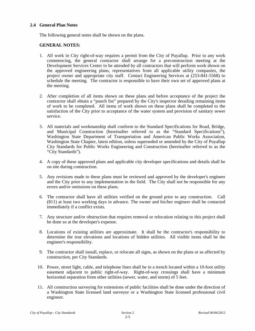
2.4 General Plan Notes
The following general notes shall be shown on the plans.
GENERAL NOTES:
1. All work in City right-of-way requires a permit from the City of Puyallup. Prior to any work commencing, the general contractor shall arrange for a preconstruction meeting at the Development Services Center to be attended by all contractors that will perform work shown on the approved engineering plans, representatives from all applicable utility companies, the project owner and appropriate city staff. Contact Engineering Services at (253-841-5568) to schedule the meeting. The contractor is responsible to have their own set of approved plans at the meeting.
2. After completion of all items shown on these plans and before acceptance of the project the
contractor shall obtain a “punch list” prepared by the City's inspector detailing remaining items of work to be completed. All items of work shown on these plans shall be completed to the satisfaction of the City prior to acceptance of the water system and provision of sanitary sewer service.
3. All materials and workmanship shall conform to the Standard Specifications for Road, Bridge,
and Municipal Construction (hereinafter referred to as the “Standard Specifications”), Washington State Department of Transportation and American Public Works Association, Washington State Chapter, latest edition, unless superseded or amended by the City of Puyallup City Standards for Public Works Engineering and Construction (hereinafter referred to as the “City Standards”).
4. A copy of these approved plans and applicable city developer specifications and details shall be
on site during construction. 5. Any revisions made to these plans must be reviewed and approved by the developer's engineer
and the City prior to any implementation in the field. The City shall not be responsible for any errors and/or omissions on these plans.
6. The contractor shall have all utilities verified on the ground prior to any construction. Call
(811) at least two working days in advance. The owner and his/her engineer shall be contacted immediately if a conflict exists.
7. Any structure and/or obstruction that requires removal or relocation relating to this project shall
be done so at the developer's expense. 8. Locations of existing utilities are approximate. It shall be the contractor's responsibility to
determine the true elevations and locations of hidden utilities. All visible items shall be the engineer's responsibility.
9. The contractor shall install, replace, or relocate all signs, as shown on the plans or as affected by
construction, per City Standards. 10. Power, street light, cable, and telephone lines shall be in a trench located within a 10-foot utility
easement adjacent to public right-of-way. Right-of-way crossings shall have a minimum horizontal separation from other utilities (sewer, water, and storm) of 5 feet.
11. All construction surveying for extensions of public facilities shall be done under the direction of
a Washington State licensed land surveyor or a Washington State licensed professional civil engineer.
City of Puyallup - City Standards Section 2 Revised 06/06/2012 2-5

12. During construction, all public streets adjacent to this project shall be kept clean of all material deposits resulting from on-site construction, and existing structures shall be protected as directed by the City.
13. Certified record drawings are required prior to project acceptance. 14. A NPDES Stormwater General Permit may be required by the Department of Ecology for this
project. For information contact the Department of Ecology, Southwest Region Office at (360)407-6300.
15. Any disturbance or damage to Critical Areas and associated buffers, or significant trees
designated for preservation and protection shall be mitigated in accordance with a Mitigation Plan reviewed and approved by the City’s Planning Division. Preparation and implementation of the Mitigation Plan shall be at the developer’s expense.
City of Puyallup - City Standards Section 2 Revised 06/06/2012 2-6
City of Puyallup - City Standards Road Revised 06/06/12 100-1
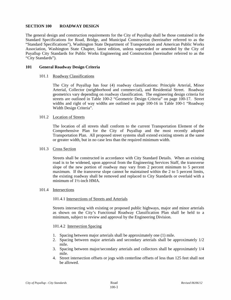
SECTION 100 ROADWAY DESIGN
The general design and construction requirements for the City of Puyallup shall be those contained in the Standard Specifications for Road, Bridge, and Municipal Construction (hereinafter referred to as the “Standard Specifications”), Washington State Department of Transportation and American Public Works Association, Washington State Chapter, latest edition, unless superseded or amended by the City of Puyallup City Standards for Public Works Engineering and Construction (hereinafter referred to as the “City Standards”).
101 General Roadway Design Criteria
101.1 Roadway Classifications
The City of Puyallup has four (4) roadway classifications: Principle Arterial, Minor Arterial, Collector (neighborhood and commercial), and Residential Street. Roadway geometrics vary depending on roadway classification. The engineering design criteria for streets are outlined in Table 100-2 “Geometric Design Criteria” on page 100-17. Street widths and right of way widths are outlined on page 100-16 in Table 100-1 “Roadway Width Design Criteria”.
101.2 Location of Streets
The location of all streets shall conform to the current Transportation Element of the Comprehensive Plan for the City of Puyallup and the most recently adopted Transportation Plan. All proposed street systems shall extend existing streets at the same or greater width, but in no case less than the required minimum width.
101.3 Cross Section
Streets shall be constructed in accordance with City Standard Details. When an existing road is to be widened, upon approval from the Engineering Services Staff, the transverse slope of the new portion of roadway may vary from 2 percent minimum to 5 percent maximum. If the transverse slope cannot be maintained within the 2 to 5 percent limits, the existing roadway shall be removed and replaced to City Standards or overlaid with a minimum of 1½-inch HMA.
101.4 Intersections
101.4.1 Intersections of Streets and Arterials
Streets intersecting with existing or proposed public highways, major and minor arterials as shown on the City’s Functional Roadway Classification Plan shall be held to a minimum, subject to review and approval by the Engineering Division. 101.4.2 Intersection Spacing
1. Spacing between major arterials shall be approximately one (1) mile. 2. Spacing between major arterials and secondary arterials shall be approximately 1/2
mile. 3. Spacing between major/secondary arterials and collectors shall be approximately 1/4
mile. 4. Street intersection offsets or jogs with centerline offsets of less than 125 feet shall not
be allowed.

City of Puyallup - City Standards Road Revised 06/06/12 100-2
5. Streets are to intersect between 90 to 85 degrees measured at centerline intersects.
101.4.3 Intersection Geometry
The geometric design at intersections to achieve drainage shall meet the following requirements:
1. At the intersection of different classifications of streets (i.e. a secondary arterial with
a collector), the center line slope and typical cross section should be carried through the intersection of the higher classified street with the lower classified street matching in a manner which will not interfere with the slope or cross section of the higher classified street.
2. Where the same class of streets intersect (i.e. residential with residential), the center line and slopes should be matched at the center line of the intersection with cross slopes varying through the intersection to allow drainage, unless directed otherwise by the Engineering Services Staff.
101.5 Cul-De-Sacs
The design shall be in accordance with City Standard Details 01.01.15 and 01.01.16. Cul-de-sacs shall not exceed 500 feet in length measured from the centerline of the intersecting roadway to the fillet of the cul-de-sac. The radius to face of curb shall not be less than 37 feet. The radius of right-of-way shall be no less than 48 feet. Cul-de-sac streets with a paved diameter of 60 feet or more may employ elongated parking bays with the approval of the Engineering Services staff.
101.6 Temporary Turnarounds and Street Ends
Where, in the opinion of the Engineering Services staff, it is desirable to provide for street access to adjoining property, proposed streets shall be extended by dedication to the boundary of such property. Such cul-de-sac streets shall be provided with a paved temporary turnaround having a roadway radius of at least 35 feet on a temporary easement. Such temporary easement shall be automatically released upon the extension and construction of said street beyond the boundary of the original subdivision. These streets shall have a type III barricade installed across the entire width of the roadway at the end of the driving surface. The words “THIS ROAD IS PLANNED TO BE EXTENDED IN THE FUTURE” shall be stenciled in 6-inch white letters on pavement approximately 10 feet from barricade in accordance with City Standard Detail 01.01.21.
101.7 Alleys
Alleys shall be at least 20 feet wide and constructed in accordance with City Standard Detail 01.01.09 and 01.01.10. Alleys may be provided to the rear of lots zoned for business purposes and shall not be provided in residential blocks except where the subdivider produces evidence satisfactory to the hearing examiner or city council of the need for alleys.
101.8 Sidewalks
Concrete sidewalks shall be constructed in accordance with City Standard Detail 01.02.01 or 01.02.02. Sidewalks shall be installed on both sides of streets within the public right of-way contiguous to the property line. The following minimum sidewalk widths shall apply:

City of Puyallup - City Standards Road Revised 06/06/12 100-3
Single family residential 5 feet Commercial use located in residential area 8 feet Multi-family residential 8 feet Industrial areas 8 feet Commercial areas 8 feet
101.8.1 End of Sidewalk
When new sidewalk is constructed and ends abruptly mid-block, a temporary pedestrian transition shall be constructed from the end of new sidewalk to the shoulder. If the receiving shoulder right of way is accessible to wheelchairs then the transition shall be constructed to meet all applicable State and federal standards, except that a detectable warning at the base of the transition will not be required. If the receiving shoulder right of way is not accessible to wheelchairs then a non-accessible temporary pedestrian transition constructed from the new sidewalk to the shoulder will be acceptable. All end of sidewalk pedestrian transition designs required herein shall be reviewed and approved by Engineering Services staff. 101.8.2 Curb Ramps
1. Curb ramps located in city right of way shall be designed by a licensed professional
engineer to meet all applicable State and federal requirements. 2. Two curb ramps shall be designed for each intersection corner except when the design
engineer can demonstrate that special circumstances exist which makes the construction of two ramps impractical. In such instances a single curb ramp may be permissible at the intersection corner when approved by the Engineering Services Manager.
3. The construction of a new curb ramp in city right of way shall be matched by a receiving curb ramp located at the opposite end of the crosswalk in accordance with RCW 35.68.075.
4. When work is performed which alters a street as defined by the Public Right of Way Accessibility Guidelines, and if construction of sidewalks are required, the ramps shall be constructed to meet all applicable State and federal requirements.
101.9 Curb and Gutter
Concrete curb and gutter shall be constructed in accordance with City Standard Detail 01.02.09. The minimum face of curb radii at intersections shall be 25 feet for residential streets, 35 feet for collectors and arterial streets, and at least 5 feet at the intersection of a street and alley unless otherwise determined by Engineering Services staff. Increases to these minimum values may be necessary to accommodate larger design vehicles.
101.10 Driveway Approaches
1. Driveway approaches shall be constructed in accordance with City Standard Details
for residential 01.02.12, 01.02.13, 01.02.14, 01.02.15 and for commercial 01.02.16, industrial 01.02.17, and public facilities 01.02.17.
2. No driveway entrance shall be wider than 30 feet unless otherwise approved by the Engineering Services staff.

City of Puyallup - City Standards Road Revised 06/06/12 100-4
3. The driveway approach within public right-of-way shall slope toward the street unless otherwise approved by the Engineering Services staff.
4. See Section 204.2.6 for additional information regarding culvert pipes for driveways. 5. The total driveway width for any one ownership on any one street shall not exceed 50
percent of the ownership on that street. Residential driveway approaches shall be a minimum of 3 feet away from a property line.
6. The sidewalk ramp at a Commercial Approach 01.02.16 and 01.02.19, or at a Residential Driveway Alternate 1 (01.02.13), shall be increased in length as necessary so that the sidewalk ramp slope does not exceed 8.3 percent, except that the sidewalk ramp length shall not be required to exceed 15 feet.
7. For proposed street construction projects where Commercial Approach 01.02.16, 01.20.19, and/or Residential Driveway Alternate 1 (01.02.13) will be utilized the design engineer shall review the proposed driveway locations relative to each other and to adjacent existing driveways so that potential ADA accessibility issues along the affected sidewalk route are resolved prior to construction.
8. Along the circumference of a residential cul-de-sac mountable curb and gutter may replace the construction of standard curb, gutter and driveway approaches when approved by the Engineering Services Manager. If mountable curb and gutter is approved at a cul-de-sac then a suitable modified driveway approach design shall be concurrently required to be submitted for approval by the Engineering Services Manager.
101.10.1 Driveway Approaches onto Major/Secondary Arterials and Collectors 1. Single family residential driveways shall not access directly onto major/secondary
arterials or collectors unless approved by the Engineering Services staff. 2. Driveways allowed for commercial, industrial, public facilities, and residential uses
shall be combined whenever possible. 3. Driveways shall be aligned across roadway when possible. 4. Driveways shall be no closer than 300 feet for major/secondary arterials and 150 feet
for collectors from the nearest intersection. 5. Minimum spacing between driveways shall be 300 feet for major/secondary arterials
and 150 feet for collectors, measured between closest edge of each driveway. A reduction of these widths will be considered on a case-by-case basis. Where 150 feet separation cannot be maintained between driveways on a neighborhood collector, driveway access shall be limited to one driveway per parcel. Further subdivision of the property will necessitate a shared private access/road.
101.11 Monuments
Monuments shall be installed in accordance with City Standard Detail 01.01.17. Concrete monuments shall be set at all points of intersection of streets, at angle points of curvature in each street (PCs and PTs), and at all center points of cul-de-sac heads. When streets are not centered within the right-of-way, the engineering as-built plans shall clearly show offset distance to the nearest .01 foot.
101.12 Dead End Streets
1. Dead end streets shall be signed with a “Dead End” sign at the entrance to the street.

City of Puyallup - City Standards Road Revised 06/06/12 100-5
2. A street network which has only one point of ingress/egress shall have a “No Outlet” sign located at the entrance.
3. Dead end streets that are planned to be extended in the future shall have a type III barricade installed across the entire width of the roadway at the end of the driving surface. A sign with the words “THIS ROAD IS PLANNED TO BE EXTENDED IN THE FUTURE” shall be placed at the center of the barricade in accordance with City Standard Detail 01.01.21. This wordage shall also be stenciled on the road in 6-inch letters using white traffic paint.
101.13 Channelization and Signage
Channelization and signage shall be in accordance with the latest Manual on Uniform Traffic Control Devices (MUTCD), and/or WSDOT Standard Specifications. Plans for channelization and signage shall be on separate drawings from the street plan/profile sheets. Contractor is responsible for paying for signs required for development and shall coordinate work with City.
101.13.1 Stop Signs and Stop Bars
1. All stop sign controlled intersections with a painted crosswalk shall have a stop bar
located a minimum of 4 feet in advance of the crosswalk. 2. If the intersection warrants a traffic signal, no stop signs shall be placed. All
intersections with a traffic signal shall have stop bars on all approaching lanes, regardless if there is a painted crosswalk or not.
3. The City Standard width for stop bars shall be 24 inches wide. Material shall be as described in the City Standard Detail 01.03.11.
4. Stop Signs at Intersections with Major/Secondary Arterials Stop signs with stop bars shall be used on all residential/collector streets intersecting major arterials. The exception shall be if the street intersecting the arterial is an alley. In this case, an engineer study will be performed to determine if a stop bar with the stop sign is warranted. When the stop sign can be placed, the stop bar shall be in line with the stop sign. If due to site conditions the stop sign must be placed further back, then the stop bar shall be placed 4 feet minimum from the edge of the intersecting lane or extension of the face of curb.
5. Stop Signs at Residential Streets Intersecting with a Collector Stop signs shall be placed on all residential streets that intersect a collector. For new installations stop bars shall be omitted until traffic patterns have been established, and a traffic study determines if they are warranted. Existing intersections of residential and collectors shall be investigated as necessary on a case-by-case study to determine if additional visibility or a stopping guide is warranted.
6. Stop Signs Where Residential Streets Intersect Residential Streets Residential streets intersecting residential streets shall have a traffic study performed to determine if a stop or yield sign is necessary. Warrants shall meet the minimum warrants as depicted in the latest edition of the MUTCD. If the intersection warrants a stop sign, no stop bar shall be placed unless the traffic study determines one is necessary.
City of Puyallup - City Standards Road Revised 06/06/12 100-6
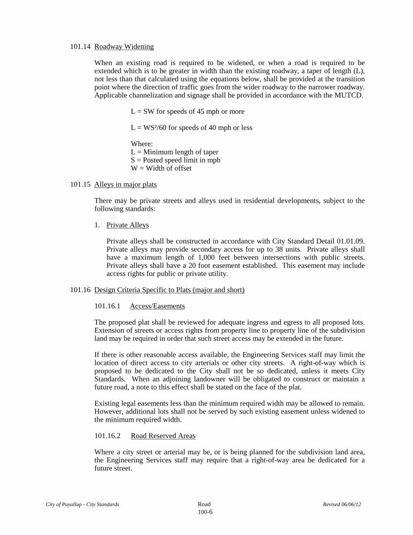
101.14 Roadway Widening When an existing road is required to be widened, or when a road is required to be extended which is to be greater in width than the existing roadway, a taper of length (L), not less than that calculated using the equations below, shall be provided at the transition point where the direction of traffic goes from the wider roadway to the narrower roadway. Applicable channelization and signage shall be provided in accordance with the MUTCD.
L = SW for speeds of 45 mph or more L = WS²/60 for speeds of 40 mph or less Where: L = Minimum length of taper S = Posted speed limit in mph W = Width of offset
101.15 Alleys in major plats
There may be private streets and alleys used in residential developments, subject to the following standards:
1. Private Alleys
Private alleys shall be constructed in accordance with City Standard Detail 01.01.09. Private alleys may provide secondary access for up to 38 units. Private alleys shall have a maximum length of 1,000 feet between intersections with public streets. Private alleys shall have a 20 foot easement established. This easement may include access rights for public or private utility.
101.16 Design Criteria Specific to Plats (major and short)
101.16.1 Access/Easements
The proposed plat shall be reviewed for adequate ingress and egress to all proposed lots. Extension of streets or access rights from property line to property line of the subdivision land may be required in order that such street access may be extended in the future.
If there is other reasonable access available, the Engineering Services staff may limit the location of direct access to city arterials or other city streets. A right-of-way which is proposed to be dedicated to the City shall not be so dedicated, unless it meets City Standards. When an adjoining landowner will be obligated to construct or maintain a future road, a note to this effect shall be stated on the face of the plat.
Existing legal easements less than the minimum required width may be allowed to remain. However, additional lots shall not be served by such existing easement unless widened to the minimum required width.
101.16.2 Road Reserved Areas
Where a city street or arterial may be, or is being planned for the subdivision land area, the Engineering Services staff may require that a right-of-way area be dedicated for a future street.

City of Puyallup - City Standards Road Revised 06/06/12 100-7
101.16.3 Lot Access
The subdivision of land into a plat shall be such as to provide access to each lot from a public or private street. Private streets may be permitted or platted in any residential or planned development subdivision, pursuant to standards specified in this code. Every subdivided property shall be served from a public dedicated street or panhandle or approved private roadway.
101.16.4 Panhandle Access
A lot within a subdivision may be permitted with a panhandle access, provided the panhandle shall have a minimum width of 20 feet and a maximum length of 200 feet and shall serve no more than one (1) lot. Panhandle accesses will not be allowed unless they are separated by at least one (1) lot width.
101.16.5 Access Serving Two or More Dwelling Units
Minimum access to all lots within a subdivision shall be provided by a dedicated, constructed, and maintained city street or private road. The Engineering Services staff shall have the authority to approve any new dedicated right-of-way and improvements within a plat and shall have the authority to approve any addition to existing dedicated right-of-way and improvements within a plat. (See Table 100-1) The authority shall be deemed to constitute an acceptance by the public of the dedication, provided the decision together with his/her finding of fact in each case is based upon the following criteria and standards as minimum conditions of approval: *Any dedicated public roads or private roads greater than 150’ is subject to the requirement of a fire department turnaround per the Fire Code Official.
1. Dedicated Public Road Serving 1-2 dwelling units
a. Streets serving 1-2 dwelling units shall have a minimum pavement width of 15
feet with two 2½-foot gravel shoulders and a maximum length of 200 feet. b. Streets serving 1-2 dwelling units and with a length greater than 200 feet shall
have a minimum width of 30 feet consisting of 24 feet from face of curb to face of curb, curb and gutter, fire department turnaround, and storm drainage.
2. Dedicated Public Road Serving 3-4 dwelling units
a. Streets serving 3-4 dwelling units shall have a minimum width of 30 feet
consisting of 24 feet from face of curb to face of curb, curb and gutter, and a maximum length of 200 feet.
b. Streets serving 3-4 dwelling units and with a length greater than 200 feet shall have a minimum width of 30 feet consisting of 24 feet from face of curb to face of curb, curb and gutter, fire department turnaround, and storm drainage.
3. Private Road Serving 1-2 dwelling units a. Streets serving 1-2 dwelling units shall have a minimum width of 20 feet
consisting of 15 feet of asphalt with two 2½-foot gravel shoulders, an inverted crown, and shall have a maximum length of 200 feet.

City of Puyallup - City Standards Road Revised 06/06/12 100-8
4. Private Road Serving 3-4 dwelling units
a. Streets serving 3-4 dwelling units shall have a minimum width of 30 feet consisting of 24 feet from face of curb to face of curb, curb and gutter, and a maximum length of 200 feet.
5. All streets, dedicated or private, as required in this manual shall be improved with a
permanent street as approved by the Engineering Services staff. Improvements shall include but not be limited to, base course, permanent hard surface, and drainage control as approved by the Engineering Services staff. Sanitary sewers and water mains shall be designed and installed to serve all lots that could be served from said dedicated or private streets.
6. In addition to other standards required by this manual, the Planning Director or the
Engineering Services staff may require additional standards and conditions or may modify the standards and conditions in such a manner as is necessary to:
a. Maintain the intent and purpose of this manual; and b. Assure that a degree of compatibility shall be maintained with respect to
properties and existing or potential uses within the general area; and c. Preserve the public health, welfare, and safety.
102 Street Lighting Specifications
Street lighting along street frontage for all subdivision, commercial, multi-family and industrial developments shall be designed and provided by the developer's engineer. The design plans shall be stamped and signed by a Washington State licensed professional civil engineer. The installation shall be in accordance with City Standard Details and the National Electric Code. The installation shall be inspected by the Washington State Department of Labor and Industries Electrical Inspection Division. The design shall meet the following design criteria. 102.1 30-Foot Steel Street Light Standard
1. Dimensions
Street light standards shall provide a mounting height of 30 feet 0 inches plus or minus 6 inches with a nominal 8-foot mast arm for residential and 12-foot mast arm for commercial. When a street light is to be installed greater than 4 feet from the edge of the driving surface the street light mast arm shall be increased to a dimension that provides a minimum of a 3-foot overhang onto the driving surface. The pole and base shall be designed accordingly. Base plate shall have slotted holes to accommodate 1-inch anchor bolts and 11½-inch bolt circle with minimum clearance of 1 inch between bolt and pole.
Handhole center shall be located approximately 12 inches from the base plate, rotated 90 degrees from mast arm on the side opposite of oncoming traffic.
2. Strength
Poles shall meet all strength requirements of AASHTO for 90 mph isotach when used with a luminaire weighing 48 pounds with an E.P.A. of 1.1 square feet.

City of Puyallup - City Standards Road Revised 06/06/12 100-9
3. Finish
The poles and all hardware shall be hot dipped galvanized, minimum 3 mil thickness. All attaching bolts and screws that are not galvanized shall be stainless steel. Mast arm attachment shall be secured by three (3) bolts. Each pole shall have handhole (with cover), ground lug, and removable pole cap. Each city pole shall have a black 4” to 6” letter “C” stenciled on the roadway side of the pole 16” above grade.
102.2 Anchorage
Poles shall be anchored with four (4) bolts, 1- x 36- x 4-inch #8 UNC with hot-dipped galvanizing after threads are cut. Galvanized area shall extend from threaded end for a minimum of 12 inches. Bolts shall be provided with two (2) galvanized nuts and flat washers for leveling. Shims will not be allowed. A non-shrinking grout shall be installed with one ½ inch drain hole under the base plate after the engineer has approved the pole installation.
102.3 Conduit
All conduit shall be buried a minimum of 24 inches deep unless otherwise specified. All roadway crossings shall be rigid metallic or schedule 80 PVC. Conduit shall conform to Section 9-29 of WSDOT Standard Specifications. Schedule 40 PVC may be used in locations other than roadway crossings.
102.4 Junction Boxes (when required)
Junction boxes shall be installed at locations as shown on the plans. They will conform to WSDOT Standard Plan J-lla. They shall be level with the sidewalk grade and firmly bedded to prevent future settling. The cover shall be galvanized and grounded. The letters “LT” and “ELECTRIC” shall be etched on the cover.
102.5 Conductors, Wires, etc.
Wire conductors for underground feeder runs and for circuitry from the in-line fuse in the poles to the junction box shall be 600-volt, single conductor stranded copper and insulated with USE grade polyvinyl chloride compound or approved equal in accordance with the Insulated Power Cable Engineer's Association Specifications, minimum size AWG 8. An AWG 8 green insulated stranded copper wire will be run from the service ground rod to the safety ground lug on each pole. Feeders shall be sized in accordance with the National Electrical Code. Wires inside pole between ballast and in-line fuses shall be Rome 2C AWG 10 stranded pole and bracket wire or approved equal. Splices will be allowed in junction boxes and pole bases only. No more than 2 conduits will be allowed inside street light pole.
102.6 Fuses
Luminaire fusing and electrical connections at light standard bases shall conform to Section 9-29.7 of the WSDOT Standard Specifications and as shown on the Uniform Luminaire Wiring Detail in the Appendix. In-line fuse holders shall be SEC model 1791-SF with FNM-5 fuses or approved equal.
City of Puyallup - City Standards Road Revised 06/06/12 100-10
102.7 Electrical Services
1. All electrical services shall be Tesco service cabinet catalog #26-000, skyline service cabinet series 47700-p2 or approved equivalent.
2. Contractor is to verify that detail specifications and equipment locations meet with serving utility’s requirements and City of Puyallup engineering requirements.
3. Conduit size and quantity as required by plans of N.E.C. 4. It shall be the contractor’s responsibility to coordinate the installation of the street
light system with all utilities, private and public, to avoid schedule and location conflicts.
5. For residential street lighting the contractor shall be responsible to install one meter for the plats lighting system per Puget Sound Energy requirements. On very large plats Puget Sound Energy may require more than one meter.
6. Base of service cabinet shall be sealed with silicone or approved equivalent and have a half inch drain hole.
102.8 Luminaires and Lamps
One (1) of the following General Electric flat lens cobra heads shall be used as indicated on plans:
M2AC10S3M2GMC32 = 100 Watt, 240V (Residential) M2AC15S3M2GMC32 = 150 Watt, 240V (Signals) M2AC20S3M2GMC32 = 200 Watt, 240V (Arterials)
The City will energize the streetlight system when a home is occupied adjacent to the street light or immediately across the street. At the developer’s request, any or all streetlights may be energized prior to the occupancy of homes. However, the developer shall assume full responsibility for electrical power costs and repair costs due to damage from vandalism.
102.9 Photo cells/shorting caps Each luminaire shall be supplied with one (1) photo cell and one (1) shorting cap, to be installed at the direction of the City of Puyallup Signal Technician. Photo cell shall be Fisher Pierce PE Cell model # 7790B.
102.10 Safe Wiring Labels
The contractor is advised that Safe Wiring Labels required by Labor and Industries shall apply on this project. (electrical inspection sticker).
102.11 Guarantee
The contractor shall surrender to the City of Puyallup any guarantee or warranty acquired by them as a normal trade practice in connection with the purchase of any materials or items used in the construction of the illumination.
102.12 Location
In general, street lights shall be located on the highest corner of the intersection. One street light will be placed at all new intersections. All new signal poles shall be equipped
City of Puyallup - City Standards Road Revised 06/06/12 100-11
with a luminaire arm. All other spacing of streetlights will be determined by the adjacent roadway classification: PRINCIPAL ARTERIALS (POSTED SPEEDS 35-45 MPH; 20,000+ADT) Commercial & Industrial Land Use Categories 150 ft Residential Land Use Categories 150 ft MINOR ARTERIALS (POSTED SPEEDS 35-45 MPH; 8,000-20,000 ADT) Commercial & Industrial Land Use Categories 150 ft Residential Land Use Categories 300 ft COMMERCIAL COLLECTOR (POSTED SPEED 30 MPH; 2,500-8,000 ADT) Commercial & Industrial Land Use Categories 150 ft NEIGHBORHOOD COLLECTOR (POSTED SPEED 30 MPH; 1,200-3,500 ADT) Residential Land Use Categories 300 ft LOCAL STREETS (POSTED SPEED 25 MPH; UP TO 1,500 ADT) Residential Land Use Categories 300 ft Notes: 1. Distances are measured along roadway centerline typical. Pole placement is
staggered, alternating sides of the roadway if possible. 2. All street light poles shall be per City Standard Detail 01.05.01 through 01.05.09. 3. Local streets shall have one street light at all intersections, at the fillet of cul-de-sac
and every 300 ft. 4. Light poles located within the Pedestrian Oriented Commercial and Fair zones shall
be painted hunter green. Poles shall be equipped with globe style luminaries: Union Metal Nostalgia series, design NL 109, with 70 watt high pressure sodium lamps mounted 12 feet above ground to the bottom of the bracket.
5. Where roads divide two different zone classifications, the commercial/industrial zone shall take precedence, unless otherwise approved by the Engineering Services staff.
6. All proposed lighting plans shall be submitted and approved by Engineering Services staff prior to installation. Plans shall be submitted on 24” x 36” paper and stamped by a licensed Professional Engineer in the State of Washington.
7. Street lights shall be located 24” minimum from face of curb unless directed otherwise by the Engineering Services Staff.
8. If a street changes direction at sufficient angle and is a substantial distance from another light location as determined by the Engineering Services staff an additional light may be added.
9. Street lights are considered traffic safety items, and shall be completed and energized prior to final plat or occupancy approval. Traffic safety shall mean both vehicles and pedestrian safety.
10. Street lights are not intended to light private property nor provide home security.
102.13 Installation
It shall be the contractor’s responsibility to coordinate the installation of the street light system with all utilities, private and public, to avoid schedule and location conflicts. The contractor shall provide written permission from Puget Sound Energy for the electrical service location and a copy of the load calculations to the City of Puyallup Engineering

City of Puyallup - City Standards Road Revised 06/06/12 100-12
Technician. The contractor shall contact the City at (253) 841-5593 when the light is ready to be energized and the City will contact Puget Sound Energy to set up an account.
102.14 Meter
For residential street lighting the contractor shall be responsible to install one meter for the plats lighting system per Puget Sound Energy requirements. On very large plats, Puget Sound Energy may require more than one meter.
103 Roadway Plan Requirements
The plans for street design shall conform to the requirements of Section 2.0 herein. The following requirements shall also be shown on the plans where applicable.
103.1 Road and Storm Plans:
• Plan and profile views per Section 2.2 • All existing trees 6 inches in diameter or larger, which trees are proposed to be
removed, and which are to remain • Existing and proposed contours at 2-foot intervals • The fill and/or excavation quantities in cubic yards • The type of fill material and compaction requirements • State whether or not the fill material will be placed upon native or stripped vegetation. • Cross sections at 200-foot-minimum intervals showing the fill/grading shall be shown
on the plans through all properties, and 30 feet beyond the property lines. Scale shown shall be consistent with the requirements of Section 2.1.9.
• Limits of grading • Street names • Center line bearings • Center line/baseline stationing • Center line elevations at 50-foot intervals, except as otherwise stated • Where transverse slope (crown) varies from 3 percent, include gutter line elevations
at 50-foot intervals, and the beginning, end, and other critical locations throughout the duration of slope variations (i.e., PCs, PTs, BVCs, EVCs, and slope transition changes).
• Centerline grade shall be in percentage (%). • Horizontal curve datum at center line • Vertical curve datum at center line • Intersection gutter line elevations at 1/4 points and right-of-way curve • Intersection elevation datum at 1/4 points of radii • Accurate locations of monuments at all center line intersections, cul-de-sacs, PCs,
PTs, and PRCs • Location, length, width of sidewalks, and driveways • Length, type, and location of curb and gutter • Wheelchair ramp locations • Right-of-way and width; lot/subdivision lines and street addresses • Right-of-way radii • Curb-to-curb pavement width • Mailbox design and/or placement/replacement • Street landscaping • Standard street construction notes • Legend (complete for existing and new) • Storm drainage system
City of Puyallup - City Standards Road Revised 06/06/12 100-13
• Height and profile of existing or proposed retaining structures • Delineation of critical areas • Measures for protection of trees and/or landscaping required to be retained • Utility locations (new and existing) for:
- Water system - Sanitary Sewer System - Gas - Telephone - Power - Cable TV - Address any horizontal or vertical utility conflicts
• For residential street lighting the contractor shall be responsible to install one meter for the plat lighting system per Puget Sound Energy requirements. On very large plats, Puget Sound Energy may require more than one meter.
103.2 Street Light Plans:
• Street light layout plans shall be on separate drawings from the street plan/profile
sheets. The final locations shall be determined by the Engineering Services Staff after the City receives a copy of the Puget Power transformer layout design drawings. Street light bases shall be located 36 inches from face of curb to center of light standard bolt circle.
• Street light disconnects shall be located near the power transformers. • Street light conduit for wiring shall be located within the utility easement for power,
gas, telephone, and cable TV wherever possible. • Street light: location, type, height, and wattage • Service cabinets: location and type • Conduits and wire: location, type, size, and length • Junction boxes: locations and types
103.3 Channelization and Signing Plans:
• Incorporated with “Street Light Plans” • Lane markers: locations and types • Pavement markings: locations and types • Signs: locations, types, and mountings • Painted street curbs
103.4 Signalization Plans:
• Separate detailed plans required • Pole base locations • Video detection: camera mounting and detection zone location • Conduit location • Details of traffic signal system to be reviewed and approved by the City Traffic
Engineer • Location of power source • Refer to Traffic Signal Design Manual, Appendix D, for complete information.
City of Puyallup - City Standards Road Revised 06/06/12 100-14
104 Roadway Plan Notes
The following notes shall be shown on the plans.
ROADWAY NOTES: 1. All work in City right-of-way requires a permit from the City of Puyallup. Prior to any work
commencing, the general contractor shall arrange for a preconstruction meeting at the Development Services Center to be attended by all contractors that will perform work shown on the engineering plans, representatives from all applicable Utility Companies, the project owner and appropriate City staff. Contact Engineering Services to schedule the meeting (253) 841-5568. The contractor is responsible to have their own approved set of plans at the meeting.
2. After completion of all items shown on these plans and before acceptance of the project, the
contractor shall obtain a “punch list” prepared by the City's inspector detailing remaining items of work to be completed. All items of work shown on these plans shall be completed to the satisfaction of the City prior to acceptance of the water system and provision of sanitary sewer service.
3. All materials and workmanship shall conform to the Standard Specifications for Road, Bridge,
and Municipal Construction (hereinafter referred to as the “Standard Specifications”), Washington State Department of Transportation and American Public Works Association, Washington State Chapter, latest edition, unless superseded or amended by the City of Puyallup City Standards for Public Works Engineering and Construction (hereinafter referred to as the “City Standards”).
4. A copy of these approved plans and applicable city developer specifications and details shall
be on site during construction. 5. Any revisions made to these plans must be reviewed and approved by the developer's engineer
and the Engineering Services Staff prior to any implementation in the field. The City shall not be responsible for any errors and/or omissions on these plans.
6. The contractor shall have all utilities verified on the ground prior to any construction. Call
(811) at least two working days in advance. The owner and his/her engineer shall be contacted immediately if a conflict exists.
7. Any structure and/or obstruction which requires removal or relocation relating to this project,
shall be done so at the developer's expense.
8. Monuments shall be installed at all street intersections, at angle points, and points of curvature in each street. All boundary monuments must be installed according to the Washington State subdivision laws.
9. Curb and gutter installation shall conform to City Standard Detail 01.02.09.
10. Sidewalks and driveways shall be installed as lots are built on. Sidewalks and driveways shall conform to City Standard Detail 01.02.01, 01.02.02 and 01.02.12. If asphalt is damaged during replacement of curb and gutter, the repair shall conform to City Standard Detail 01.02.10.

City of Puyallup - City Standards Road Revised 06/06/12 100-15
11. The surrounding ground (5 feet beyond the base) for all power transformers, telephone/TV pedestals, and street light main disconnects shall be graded to a positive 2 percent slope from top of curb.
12. Signage and traffic control devices are safety items and shall be installed prior to issuance of
any certificate of occupancy or plat approval. However, in larger developments, exact locations of stop and yield signs may need to be determined after full buildout when traffic patterns have been established. In this case, contractor shall provide indicated “City-placed” signs, signposts, and brackets to the City sign specialist (253) 841-5471 for later installation by the City. All signage shall be in accordance with the Manual on Uniform Traffic Control Devices (MUTCD).
13. Prior to any sign or striping installation or removal the Contractor shall contact the City sign
specialist (253) 841-5471 to arrange for an on-site meeting to discuss placement and uniformity.
14. New or revised stop signs or yield signs shall be advance warned using the procedure outlined
in the MUTCD. Advance warning signs and flags shall be maintained by installer for 30 days and then removed.
105 Illumination General Notes The following notes shall be shown on the plans. ILLUMINATION NOTES:
1. All work shall be in accordance with City of Puyallup public works standards and WSDOT standards and specifications.
2. The locations of features shown are approximate and shall be verified by the contractor prior to construction start.
3. Utility locations are approximate and shall be verified in the field by the contractor prior to any illumination work.
4. All work shall be consistent with utility agency requirements. The contractor shall coordinate with affected utility agencies throughout the project. The contractor shall be responsible for any damage to utilities.
5. Conduit locations are shown for illustrative purposes. Actual locations shall be determined by the contractor in the field.
6. Contractor shall coordinate with the city signal/illumination technician at 253.405.4390 prior to construction.
7. The location of all conduits, junction boxes, poles, and cabinets shown on this plan may be adjusted in the field to avoid conflicts and meet ADA requirements. All final locations shall be approved by the city traffic engineer prior to construction.

City of Puyallup - City Standards Road Revised 06/06/12 100-16
8. Junction box locations shown are for illustrative purposes only. Junction boxes shall be field located by the contractor with direction from the city.
9. Contractor shall adjust junction box lids to be flush with top of sidewalk.
10. Any new junction box which will be located within or partially within sidewalk shall have lids and frames with a non-slip coating on the top surface equal to MEBAC1 or SLIPNOT#3.
City of Puyallup - City Standards Road Revised 03/09/10 100-17
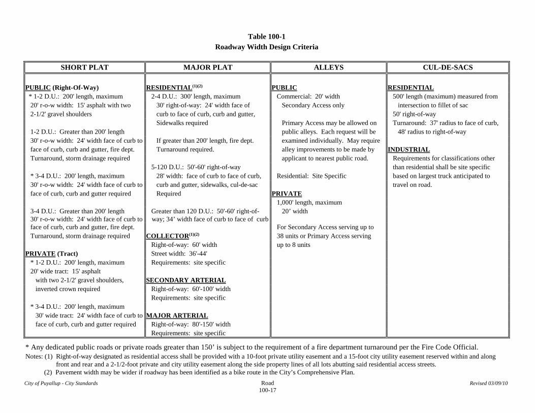
Table 100-1
Roadway Width Design Criteria
SHORT PLAT MAJOR PLAT ALLEYS CUL-DE-SACS
PUBLIC (Right-Of-Way) RESIDENTIAL(1)(2) PUBLIC RESIDENTIAL * 1-2 D.U.: 200' length, maximum 2-4 D.U.: 300' length, maximum Commercial: 20' width 500' length (maximum) measured from 20' r-o-w width: 15' asphalt with two 30' right-of-way: 24' width face of Secondary Access only intersection to fillet of sac 2-1/2' gravel shoulders curb to face of curb, curb and gutter, 50' right-of-way Sidewalks required Primary Access may be allowed on Turnaround: 37' radius to face of curb, 1-2 D.U.: Greater than 200' length public alleys. Each request will be 48' radius to right-of-way 30' r-o-w width: 24' width face of curb to If greater than 200' length, fire dept. examined individually. May require face of curb, curb and gutter, fire dept. Turnaround required. alley improvements to be made by INDUSTRIAL Turnaround, storm drainage required applicant to nearest public road. Requirements for classifications other 5-120 D.U.: 50'-60' right-of-way than residential shall be site specific * 3-4 D.U.: 200' length, maximum 28' width: face of curb to face of curb, Residential: Site Specific based on largest truck anticipated to 30' r-o-w width: 24' width face of curb to curb and gutter, sidewalks, cul-de-sac travel on road. face of curb, curb and gutter required Required PRIVATE
1,000' length, maximum 3-4 D.U.: Greater than 200' length 30' r-o-w width: 24' width face of curb to
Greater than 120 D.U.: 50'-60' right-of- way; 34’ width face of curb to face of curb
20’ width
face of curb, curb and gutter, fire dept. For Secondary Access serving up to Turnaround, storm drainage required COLLECTOR(1)(2) 38 units or Primary Access serving Right-of-way: 60' width up to 8 units PRIVATE (Tract) Street width: 36'-44' * 1-2 D.U.: 200' length, maximum Requirements: site specific 20' wide tract: 15' asphalt with two 2-1/2' gravel shoulders, SECONDARY ARTERIAL inverted crown required Right-of-way: 60'-100' width Requirements: site specific * 3-4 D.U.: 200' length, maximum 30' wide tract: 24' width face of curb to MAJOR ARTERIAL face of curb, curb and gutter required Right-of-way: 80'-150' width Requirements: site specific
* Any dedicated public roads or private roads greater than 150’ is subject to the requirement of a fire department turnaround per the Fire Code Official.
Notes: (1) Right-of-way designated as residential access shall be provided with a 10-foot private utility easement and a 15-foot city utility easement reserved within and along front and rear and a 2-1/2-foot private and city utility easement along the side property lines of all lots abutting said residential access streets.
(2) Pavement width may be wider if roadway has been identified as a bike route in the City’s Comprehensive Plan.
City of Puyallup - City Standards Road Revised 03/09/10 100-18
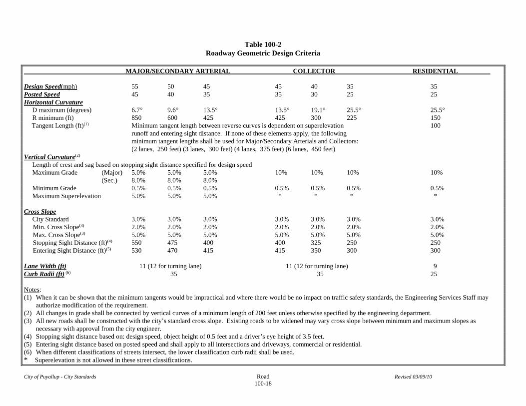
Table 100-2
Roadway Geometric Design Criteria
MAJOR/SECONDARY ARTERIAL COLLECTOR RESIDENTIAL Design Speed(mph) 55 50 45 45 40 35 35 Posted Speed 45 40 35 35 30 25 25 Horizontal Curvature D maximum (degrees) 6.7° 9.6° 13.5° 13.5° 19.1° 25.5° 25.5° R minimum (ft) 850 600 425 425 300 225 150 Tangent Length (ft)(1) Minimum tangent length between reverse curves is dependent on superelevation 100 runoff and entering sight distance. If none of these elements apply, the following minimum tangent lengths shall be used for Major/Secondary Arterials and Collectors: (2 lanes, 250 feet) (3 lanes, 300 feet) (4 lanes, 375 feet) (6 lanes, 450 feet) Vertical Curvature(2) Length of crest and sag based on stopping sight distance specified for design speed Maximum Grade (Major) 5.0% 5.0% 5.0% 10% 10% 10% 10% (Sec.) 8.0% 8.0% 8.0% Minimum Grade 0.5% 0.5% 0.5% 0.5% 0.5% 0.5% 0.5% Maximum Superelevation 5.0% 5.0% 5.0% * * * * Cross Slope City Standard 3.0% 3.0% 3.0% 3.0% 3.0% 3.0% 3.0% Min. Cross Slope(3) 2.0% 2.0% 2.0% 2.0% 2.0% 2.0% 2.0% Max. Cross Slope(3) 5.0% 5.0% 5.0% 5.0% 5.0% 5.0% 5.0% Stopping Sight Distance (ft)(4) 550 475 400 400 325 250 250 Entering Sight Distance (ft)(5) 530 470 415 415 350 300 300 Lane Width (ft) 11 (12 for turning lane) 11 (12 for turning lane) 9 Curb Radii (ft) (6) 35 35 25 Notes: (1) When it can be shown that the minimum tangents would be impractical and where there would be no impact on traffic safety standards, the Engineering Services Staff may
authorize modification of the requirement. (2) All changes in grade shall be connected by vertical curves of a minimum length of 200 feet unless otherwise specified by the engineering department. (3) All new roads shall be constructed with the city’s standard cross slope. Existing roads to be widened may vary cross slope between minimum and maximum slopes as necessary with approval from the city engineer. (4) Stopping sight distance based on: design speed, object height of 0.5 feet and a driver’s eye height of 3.5 feet. (5) Entering sight distance based on posted speed and shall apply to all intersections and driveways, commercial or residential. (6) When different classifications of streets intersect, the lower classification curb radii shall be used. * Superelevation is not allowed in these street classifications.
City of Puyallup - City Standards Storm Revised 3/14/2016 200-1
SECTION 200 STORMWATER MANAGEMENT 200.1 General Stormwater Requirements
1. The general design and construction requirements for the City of Puyallup shall be those contained in the Standard Specifications for Road, Bridge, and Municipal Construction (hereinafter referred to as the “Standard Specifications”), Washington State Department of Transportation and American Public Works Association, Washington State Chapter, latest edition; and the Uniform Plumbing Code as adopted by the Washington State Building Code Council, latest edition, unless superseded or amended by the City of Puyallup Design Standards for Public Works Engineering and Construction (hereinafter referred to as the “City Standards”).
2. The following paragraphs outline the requirements specific to the City of Puyallup which
shall be used in conjunction with the regulations noted above and the design principles outlined in the following referenced stormwater manuals. Any conflict or inconsistency in the information provided by these documents shall be resolved by giving precedence in the following order:
1. City of Puyallup Phase II Municipal Stormwater Permit (NPDES
Permit) 2. City of Puyallup Municipal Code (PMC) 3. City of Puyallup Design Standards including Standard Details 4. City of Puyallup Stormwater Management Plans (Comprehensive
Plans, Basin Plans, and/or Water Clean-up Plans) 5. 2005 Dept. of Ecology Stormwater Management Manual for
Western Washington (Ecology Manual) 6. 1990 King County Surface Water Design Manual with 1994/95
Revisions 3. The City may adopt a comprehensive stormwater plan, individual watershed basin plan(s), or
water clean-up plans which may place additional stormwater requirements on a proposed project. The applicant shall incorporate any conditions required by these plans which are applicable to the proposed project. Current stormwater management plans are available on the City’s website at:
http://www.cityofpuyallup.org/services/public-works/stormwater-management/
4. Public right-of-way runoff shall be detained and treated independently from the private
stormwater facilities. This shall be accomplished by providing separate publicly maintained storm facilities within a tract or dedicated right-of-way; enlarging the private facilities to account for bypass runoff; or other methods as approved by the Engineering Services Manager.
5. All stormwater facilities associated with single-family residential plats and subdivisions shall
be located in public right-of-way or within a separate dedicated tract of appropriate dimensions and improved to the standards set forth below and in accordance with the Puyallup Municipal Code (PMC).
6. All private storm drainage facilities shall be covered by a maintenance agreement provided by
the City and recorded with Pierce County. Under this agreement, if the owner fails to properly maintain the facilities, the City, after giving the owner written notice, may perform necessary maintenance at the owner’s expense in accordance with PMC 21.10. See Section 205 for additional information.
City of Puyallup - City Standards Storm Revised 3/14/2016 200-2
7. Stormwater will not be permitted to discharge directly onto City roads or into a City system
without the prior approval of the City with the exception of single family residences. Discharges to a City system shall be into a structure such as a catch basin, manhole, through an approved curb drain, or into an existing or created City ditch. Concentrated drainage will not be allowed to discharge across sidewalks, curbs, or driveways.
8. All buildings are required to have roof downspouts and subsurface drains directed to either an
infiltration system, dispersion system, or to the stormwater conveyance system. Refer to the appropriate stormwater design manual chosen from Section 201 below for additional information on roof downspout infiltration and dispersion.
9. All stormwater facilities installed within paved areas shall be designed to withstand HS-20
load requirements. 10. Ecology block walls will not be permitted within the City of Puyallup’s stormwater facilities
as baffles. 11. For wetpond designs, the City of Puyallup will require the use of berms. Baffles shall be
second preference for the City of Puyallup, and when allowed through the use of the Alternative Methods Request (AMR) process approved by the City Engineer, shall be cast in place concrete as designed by a licensed civil engineer (structural engineer if exceeding the limitations of civil licensing).
201 Stormwater Management Requirements 201.1 Stormwater Manual Selection
1. On February 16, 2010 the City of Puyallup adopted new storm water regulations in accordance with the requirements of the City’s NPDES Permit. Permit applications shall comply with the new regulations contained in PMC Chapter 21.10 and these City Standards.
2. Any proposed project that will disturb 1-acre or greater, or is part of a larger common plan of
development or sale that will ultimately disturb 1-acre or greater, e.g., plats and binding site plans, will be required to adhere to the requirements of the 2005 Dept. of Ecology Stormwater Manual for Western Washington (hereinafter referred to as the “Ecology Manual”).
3. If a proposed project will disturb less than 1-acre, and is not part of a larger common plan of
development or sale that will ultimately disturb 1-acre or more, and increases the impervious surface of the site by more than 5,000 square feet, then the applicant may elect to use stormwater design requirements in effect prior to February 16, 2010. These requirements are contained in the 1990 King County Surface Water Design Manual with 1994/95 revisions, published by King County Department of Public Works Surface Water Management Division (hereinafter referred to as the “KC Manual”), and as further modified below.
4. Due to downstream constraints, projects located South of 12th Avenue SE within the State
Highway Basin, regardless of size, shall use the Ecology Manual as a means to prevent downstream impacts from the proposed development.
5. All applicants shall complete and submit the stormwater flowchart, Figures 3.1, 3.2, and 3.3,
contained in the City’s Phase II Municipal Stormwater Permit, Appendix I. The completed flowchart shall be submitted with the permit application and included in the Stormwater Site Plan (SSP). The link below may be used to obtain the flowchart from the Dept. of Ecology’s website:
City of Puyallup - City Standards Storm Revised 3/14/2016 200-3
http://www.ecy.wa.gov/programs/wq/stormwater/municipal/phaseIIww/wwphiipermit.html
201.2 Stormwater Site Plan (SSP)
1. All projects requiring stormwater management shall submit a Stormwater Site Plan (SSP) in accordance with Volume I, Chapter 3 of the Ecology Manual.
2. All projects requiring stormwater management shall provide an offsite analysis and mitigation
report, contained in the SSP, that conforms to the description and specific task elements described in Volume I, Section 2.6.2 of the Ecology Manual.
3. Each section of the SSP shall be individually indexed and tabbed with each permit
application, and every re-submittal thereafter, prior to review by the City.

City of Puyallup - City Standards Storm Revised 3/14/2016 200-4
202 203
This page left intentionally blank
City of Puyallup - City Standards Storm Revised 3/14/2016 200-5
204 Conveyance Systems
204.1 Conveyance System Design Flows
1. Design flows for sizing conveyance systems shall be determined using an approved calibrated continuous simulation hydrologic model, i.e., HSPF, Western Washington Hydrology Model (WWHM), MGS Flood, or KCRTS. Conveyance capacity shall be based on the historic September 17, 1969 25-year storm flow event.
Exception: For project sites in the City with tributary areas less than 10-acres, and a
developed time of concentration less than 60-minutes, either the Rational Method or Santa Barbara Urban Hydrograph Method (SBUH) may be used to determine conveyance design flows. The 25-year, 24-hour storm event total precipitation used for analysis shall be 3.5-inches.
2. Design flows for conveyance facilities that also operate as water quality or flow control
BMP’s, shall be determined using the hydrologic design method described in the stormwater manual chosen in Section 201.
3. Culverts shall be designed in accordance with Section 204.5.
204.2 Conveyance System General Requirements 1. All new pipe systems, both onsite and offsite, shall be designed with sufficient capacity to
convey and contain (at minimum) the 25-year storm flow event, assuming developed conditions for onsite tributary areas, and existing conditions for any offsite tributary areas.
2. Stormwater may be discharged directly to the Puyallup River provided the following
conditions are met:
- the project site is located within one of the direct discharge basins outlined in the 2012 Comprehensive Stormwater Drainage Plan
- the discharge is consistent with federal, state, and city regulations governing water quality and flow control
- the discharge is solely through a stable, man-made stormwater conveyance system that extends from the project site to the mean high water line of the river
- the man-made conveyance system has adequate hydraulic capacity (Note: The applicant shall provide supporting calculations of system capacity which may be subject to third party review prior to project approval.)
- the discharge will not cause, or aggravate, downstream flooding problems - the discharge does not reduce natural flows to other streams or wetlands
3. On projects considering direct discharge to the Puyallup River, conveyance capacity shall be determined based on the 25-year storm flow event and the corresponding river elevations at the specific river outfall. Reference City of Puyallup Comprehensive Storm Drainage Plan, Appendix C, Table C-9.
4. Pipe system structures may overtop for runoff events that exceed the 25-year design capacity
provided the overflow from a 100-year runoff event does not create or aggravate an existing flooding problem or erosion problem. Any overflow occurring onsite for runoff events up to and including the 100-year event must discharge at the natural location for the project site. In
City of Puyallup - City Standards Storm Revised 3/14/2016 200-6
residential subdivisions, this overflow must be contained within an onsite drainage easement, tract, covenant, or public right-of-way.
5. In areas of the City with insufficient conveyance capacity (25-year storm), new development
and redevelopment must either enlarge on-site stormwater facilities to reduce downstream flows, or construct any necessary capital improvement(s).
6. Project related off-site conveyance systems are permitted only if the downstream property
owner(s) grant easements for construction, operation, and maintenance of the system. If easements are not provided, runoff management shall conform to drainage law and shall, at a minimum, include provisions for detention, water quality, and/or dispersion prior to leaving the development site.
7. New stormwater mains shall be extended along the entire frontage of the property to be
served. 204.3 Pipe System Design Criteria
1. Basic conveyance system design shall be accomplished using the Uniform Flow Analysis
Method (Manning’s Equation). When using this method, each pipe within the conveyance system shall be sized and sloped such that its barrel capacity at normal full flow is equal to, or greater than, the required conveyance capacity described above. Pipes should not be designed to surcharge.
2. The City, at its discretion, may request a Backwater Analysis for the conveyance system
design. When a backwater calculation is required, the design engineer shall analyze the system for the 25-year and 100-year peak flows.
- If overtopping occurs, the additional flow over the ground surface shall be
analyzed using the methods for open channel flow. Any additional surface flow shall not exceed 4-inches depth at its deepest point, and shall not extend beyond half the lane width of the outside lane of the traveled way.
3. Pipe systems shall be designed to accommodate the developed condition 25-year storm flow
event with 0-feet of freeboard without overtopping catch basins and manholes.
4. Public stormwater pipe shall be minimum 12-inch diameter. Private stormwater pipe shall be minimum 12-inch diameter for mains, and minimum 8-inch diameter for laterals.
5. The minimum design velocity at full flow should be 3-feet per second. If site constraints
result in velocities less than 3-feet per second at full flow, concerns associated with sedimentation in the pipe system shall be addressed with larger pipes, closer spacing of structures, sediment basins, or other similar measures.
6. The minimum slope of the pipe shall be 0.5%.
7. All pipe reaches shall be summarized in a Conveyance Table containing the following
minimum information and included in the TIR:
City of Puyallup - City Standards Storm Revised 3/14/2016 200-7
o Pipe Reach Name o Pipe-Full Flow (cfs) o Structure Tributary Area o Water Depth at Design Flow (in) o Pipe Diameter (in) o Critical Depth (in) o Pipe Length (ft) o Velocity at Design Flow (fps) o Pipe Slope (%) o Velocity at Pipe-Full Flow (fps) o Manning’s Coefficient (n) o Percent full at Design Flow (%) o Design Flow (cfs) o HGL for each Pipe Reach (elev)
204.4 Closed System Requirements
1. Publicly maintained stormwater pipe shall be only PVC, concrete, ductile iron, or dual walled
Polypropylene pipe as follows:
a. PVC pipe shall be per ASTM D3034, SDR 35 for pipe size 15-inch and smaller and F679 for pipe size 18- to 27-inch. Minimum cover on PVC pipe shall be 3-feet.
b. Concrete pipe shall conform to AASHTO M 86, Class 2 only, for unreinforced pipe and AASHTO M 170, Classes II through V, for reinforced concrete pipe. Minimum cover on concrete pipe shall be 3-feet.
c. Ductile iron pipe shall be Class 50, conforming to AWWA C151. Minimum cover on ductile iron pipe shall be 1-foot.
d. Polypropylene Pipe (PP) shall be dual walled, have a smooth interior and exterior
corrugations and meet WSDOT 9-05.24(1). 12-inch through 30”-inch pipe shall meet or exceed ASTM F2736 and AASHTO M330, Type S, or Type D. 36-inch through 60-inch pipe shall meet or exceed ASTM F2881 and AASHTO M330, Type S, or Type D. Testing shall be per ASTM F1417. Minimum cover over Polypropylene pipe shall be 3-feet.
2. Solid wall, fusion-welded high density polyethylene pipe (HDPE), may be used in unique
situations, i.e. steep slopes or horizontal directional boring, upon approval of the Engineering Services Manager or Public Works Director. Projects utilizing HDPE pipe shall include consideration of the material’s thermal expansion/contraction properties for the design of connections and anchorages. Minimum cover on buried HDPE pipe shall be 3-feet.
If approved, HDPE pipe shall conform to the following criteria:
- compliance with the requirements of Type III C5P34 as tabulated in ASTM
D1248; - shall have the PPI recommended designation of PE3408; - shall have an ASTM D3350 cell classification of 345534C; - a hydrostatic design stress rating of 800-psi based on a material with a 1600-
psi design basis determined in accordance with ASTM D2837-69; - a design working pressure of 50-psi at 73.4o F and an SDR value of 32.5.
3. Privately maintained stormwater pipe shall be PVC, concrete, or ductile iron meeting the
same criteria as specified above.

City of Puyallup - City Standards Storm Revised 3/14/2016 200-8
Exception: The use of corrugated polyethylene pipe (CPEP) in accordance with WSDOT Standard Specifications Section 9-05.20 is acceptable for private stormwater systems. Minimum cover on CPEP pipe shall be 3-feet.
4. The use of any other pipe material shall only be allowed upon submission and approval of an
“Alternative Methods Request”. The Alternative Methods Request form shall clearly indicate the justification for a substitute pipe material other than cost savings.
5. The conveyance pipe diameter, length, material, and slope shall be included on the ‘plan
view’ in addition to the ‘profile view’ for each pipe reach.
6. Steep slope areas (over 30%) shall require all drainage to be piped from the top to the bottom in fusion-welded HDPE pipe. If slopes exceed 40%, then pipe shall be installed on the surface of the slope, with the minimum disturbance possible, and provided with engineered anchorages.
7. Roof drains, or other stormwater pipe, within 2-feet of a building shall consist of material
approved by the Uniform Plumbing Code. (i.e. PVC schedule 40, ABS schedule 40, or ductile iron).
8. For stormwater pipe crossing over sanitary sewers, a minimum of 12-inches of vertical
clearance shall be provided between the systems. If the stormwater pipe is crossing below the sanitary sewer, a minimum of 18-inches of vertical separation shall be provided.
a. A pipe sleeve is required for some installations to provide additional protection of
stormwater from potential leakage from other utilities. A pipe sleeve shall be a single section of PVC pipe (no joints) with a minimum length of 10-feet to each side of the pipe crossing. The pipe sleeve shall be placed around the stormwater pipe with the annular space between the sleeve and the stormwater pipe filled with grout.
9. A minimum of 10-feet of separation shall be provided between building structures and any
closed system, or 10-feet from the utility easement line in a public system.
10. Trees shall not be located within 10-feet horizontally of stormwater pipes unless root barriers are provided. With root barriers, trees may be no closer than 3-feet to pipes.
204.5 Culvert Design Requirements
1. Culverts and bridges associated with natural channels must convey the 100-year storm event
from the contributing area assuming fully developed conditions.
2. All other culverts and bridges shall convey the 25-year peak flow from the contributing area assuming fully developed conditions.
3. Bridges shall be the first choice for crossing streams with salmonids. Bridges proposed in streams with salmonids shall be designed to provide for fish passage in accordance with the City's critical areas regulations and the Washington State Department of Fish and Wildlife (WDFW) requirements. A WDFW Hydraulic Permit Authorization (HPA) or exemption will be required prior to permit approval.
City of Puyallup - City Standards Storm Revised 3/14/2016 200-9
4. Flow capacity shall be determined by analyzing inlet and outlet control for headwater depth. All calculations and nomographs used for culvert design shall be included in the stormwater report.
5. The maximum design headwater depth shall be 1.5 times the diameter of the culvert with no
saturation of roadbeds. Minimum culvert diameters are as follows:
- Culverts crossing under public roadways – 18-inches minimum - Roadside culverts, including driveway culverts – 15-inches minimum - Culverts on private property – 8-inches minimum
6. Inlets and outlets shall be protected from erosion by rock lining, riprap, or bio-stabilization.
7. Culvert velocity shall be 2-feet per second minimum and 15-feet per second maximum. For ductile iron, polypropylene or HDPE pipe, no maximum velocity shall be established, but an engineered outlet protection design shall be provided and included in the stormwater report.
8. Driveway culverts shall be a minimum of 20-feet in length. All driveway approaches 24-feet
and wider shall have concrete headwalls at each end of the culvert. Culverts shall have beveled end sections to match the side slope.
9. All corrugated metal pipe (CMP) culverts shall be uniformly coated inside and out with a
protective coating of asphalt in accordance with WSDOT Section 9-05.4(3) Treatment I criteria.
204.6 Open Systems Design Requirements
1. These provisions apply only to “Open Systems” which are not part of a natural drainage
system regulated under the City’s Environmentally Critical Areas Management Ordinance (CAO). Design requirements for modification of regulated natural drainage systems shall be site specific and developed in accordance with provisions contained in the CAO and approved by the Planning Department.
2. Open channels shall be sized to adequately carry the design rate of flow without damage.
Whenever practical, the channel shall be characterized as slow flowing, be wide and shallow, and natural in its appearance and functioning.
3. Open systems shall be designed with side slopes no steeper than 3H:1V and back slopes no
steeper than 2H:1V with adequate slope stabilization and a minimum freeboard of 1-foot.
4. Ditches may be either trapezoidal or ‘V’-shaped.
5. Open ditches designed at 2 to 5-feet per second (fps) shall be hydro-seeded with a grass approved by the City. Steep grades (5 to 15 fps) will require check dams, rock spalls, rip rap, or other approved energy dissipation methods.
6. A minimum of 20-feet shall be provided between a building structure and any open system.
7. Ditch cross sections shall be provided at a minimum of every 50-feet. The cross section shall
extend 25-feet beyond the top of bank on either side of the ditch and include the water surface elevation for the 2-yr, 10-yr, 25-yr and 100-yr storm events.
City of Puyallup - City Standards Storm Revised 3/14/2016 200-10
204.7 Pump System Requirements
1. Pumping stormwater is the method least desirable for conveying stormwater and is not an acceptable alternative for publicly maintained systems. When no other alternatives are feasible for privately owned systems, pump systems may be considered provided they meet the following criteria:
a. A pump system may be substituted for the City Standard control riser provided
the pump system is designed to release detained stormwater in accordance with the discharge requirements specified by the appropriate manual required in Section 201.
b. The pump system shall be used to convey water from one location or elevation to another within the limits of the project site. Gravity discharge to the downstream public conveyance system is required.
c. A backup pump shall be incorporated into the system. d. An alternative power source shall be provided, i.e., emergency generator or
battery backup power. Use of a portable generator as an alternative power source is not acceptable.
Any alternative power source shall include an auto-transfer switch that disconnects the alternative power source from the public grid.
e. External High water / Pump Failure alarm system shall be provided. f. The gravity-flow components of the drainage system to and from the pump
system must be designed so that pump failure does not result in flooding of a building, an emergency access route, an adjacent property, or cause overflow to a location other than the natural discharge point for the project site.
204.8 Vaults, Catch Basin and Manhole Requirements
1. All concrete cast-in-place stormwater structures shall be designed by a registered
professional engineer licensed in the State of Washington and shall be approved and permitted by the City of Puyallup Building Department. The building permit number shall be referenced on the engineering record drawings prior to final acceptance by the Engineering Services Department.
a. Cast-in-place vaults shall be provided with commercially available PVC or rubber
waterstop at all cold joints. The waterstop shall be physically embedded and bonded to the concrete on each side of the joint.
b. Cast-in-place manholes and catch basins shall be provided with a commercially
available flexible waterstop which expands when exposed to water. c. All waterstop material(s) shall be installed in accordance with the manufacturer’s
recommendations.
2. A stormwater structure shall be installed at the end of all dead-end mainlines, at changes in direction or slope, at changes in pipe size or material, and at pipe junctions.
City of Puyallup - City Standards Storm Revised 3/14/2016 200-11
3. Catch basins shall be provided within 50-feet of the entrance to a pipe system to provide for silt and debris removal.
4. Catch basins and manholes shall be easily accessible to maintenance vehicles, equipment,
and personnel.
5. Pipe inverts shall be matched at manholes and catch basins.
6. Maximum spacing between structures (i.e., manholes or catch basins) for closed systems shall be 400-feet of pipe length.
7. Maximum surface run (gutter flow) for storm drains on paved roadway surfaces shall be as
follows: Pavement Slope Maximum Surface Run
Less than 1% 200 ft 1% to 6% 300 ft 6% to 12% 200 ft
8. For slope grades greater than 6%, or as determined by the Engineering Services Manager or
Public Works Director, it may be necessary to use concrete pipe and manholes in lieu of catch basins to help stabilize the storm system and control pipe flow velocities.
9. The maximum depth for catch basins/manholes shall be as follows:
a. Type I Catch Basin: 5-feet, measured from the pipe invert to the finished surface. b. Type II Catch Basin: 20-feet, measured from the bottom of structure to the
finished surface. c. For depths greater than 20-feet, stormwater structures shall be designed by a
licensed professional engineer registered in the State of Washington.
10. Street drainage requirements for public systems shall be as follows:
a. The minimum longitudinal gutter slope shall be 0.5%. b. Catch basins shall be installed at all low points in the surface drainage area. c. At gutter line low points, insure positive flow to catch basins. In some situations
this may require variation from the vertical curve at the low point in the gutter line.
d. A catch basin shall be provided within 20-feet upstream of a reverse slope
driveway.
11. Catch basins and manholes within the limits of a new or redevelopment project and located in the public right-of-way, but not in the flow-line, shall be:
a. removed, or if not feasible; b. removed and replaced with a Type II Catch Basin, and; c. unless used as an inlet, provided with a round manhole ring and cover.
City of Puyallup - City Standards Storm Revised 3/14/2016 200-12
204.9 Oil Control/Spill Containment
1. Commercial, industrial, and multi-family properties shall include, at a minimum, a spill
control device in one of the end-of-the-line (lowest) manholes or catch basins in the onsite conveyance system. (prior to connecting to the public stormwater system). The spill control device shall be installed upstream of any onsite water quality or flow control facility. If no stormwater facilities are present, then the spill control device must be installed upstream from the final discharge point to the downstream drainage system.
2. The minimum requirement for a spill control device is a T-section, removable for
maintenance, located on the outlet pipe leaving a Type 1L or Type-2 catch basin. Depending on the use(s) on the site, the Engineering Services Department may require additional measures for increased protection.
204.10 Grates
1. All grates shall be cast iron or ductile iron castings.
2. Vaned grates shall be used on all public and private systems. 204.11 Storm Drain Stenciling and Marking
1. All storm drains shall be signed as follows:
a. Publicly maintained stormwater catch basins shall be signed using glued-down markers supplied by the City and installed by the project proponent.
b. Privately maintained stormwater catch basins shall be signed with pre-cut 90ml
torch down heavy-duty, intersection-grade preformed thermoplastic pavement marking material. It shall read either “Only Rain Down the Drain" or “No Dumping, Drains to Stream”.
204.12 Outfalls
1. All exposed storm lines, 12-inches in diameter and larger, shall have trash racks at both the
inlet and outlet ends, in accordance with City Standard Details.
Exception: Trash racks are required on inlet and outlet ends of all culverts greater than 18-inches in diameter. Trash racks are not required on culverts greater than 36-inches in diameter within stream corridors.
2. All concentrated discharges from stormwater conveyance systems shall be provided with
energy dissipation/erosion protection measures. 205 Stormwater Maintenance and Operation Requirements 205.1 Stormwater Facilities Maintenance
1. All publicly maintained stormwater facilities shall be within a tract, easement, or right-of-way dedicated to the City of Puyallup.

City of Puyallup - City Standards Storm Revised 3/14/2016 200-13
2. The design engineer shall provide the City with a letter certifying the proper installation of permanent stormwater controls and compliance with the approved stormwater site plan.
3. The City of Puyallup will assume maintenance and operation of public facilities located
within subdivisions one year after final construction approval of the plat and provided subsequent inspection by the City indicates the facilities have been properly maintained and are operating as designed.
4. Provision shall be made for the long-term maintenance of all stormwater facilities and shall be
accessible to maintenance vehicles and personnel. If not located in, or adjacent to a vehicle access way, then access by an improved roadway surface shall be provided.
5. Maintenance access roads shall be provided to the control structure and all drainage structures
associated with any retention/detention facility. In no case shall any structure be located further from an access way than 8-feet when measured from the front of a vehicle, or no further than 20-feet when measured from the side of a vehicle.
205.2 Maintenance Access Road Requirements
1. Materials of construction for an improved roadway surface may include asphalt concrete, cement concrete, cement-treated base (CTB), asphalt-treated base (ATB), structurally stabilized vegetated surface, crushed surfacing base course, or other surfacing as approved by the Engineering Services Department.
a. Asphalt surfaces shall conform to the City of Puyallup “Private Roadway” standard.
b. Concrete surfaces shall conform to the material requirements and thickness
specified in City Standard Detail 01.02.17 “Urban Commercial Approach – Alternate 1”.
c. CTB and ATB shall be a minimum of 10-inches thick. d. Crushed surfacing base course shall be a minimum of 10-inches thick and
conform to City of Puyallup standards. e. Structurally stabilized vegetated surfaces shall only be used on grades less than
8% and shall comply with the manufacturer’s requirements.
2. Access roads shall be designed with 48’-6” outside radius on curves, with a maximum slope not to exceed 12% and a minimum width of 15-feet. Access roads steeper than 8% shall be paved using either asphalt concrete, cement concrete, cement-treated base (CTB), or asphalt-treated base (ATB).
3. For ponds with bottom widths of 15-feet or more, the access road shall extend to the pond
bottom to a minimum 25-foot long level pad to facilitate cleaning. The access pad shall be designed in accordance with 205.2(1). For ponds less than 15-feet in width, an access road must extend along at least one (1) side of the pond.
4. A paved apron with removable bollards and/or fencing shall be provided where access roads
connect to paved public roadways.
205.3 Private Maintenance Agreements

City of Puyallup - City Standards Storm Revised 3/14/2016 200-14
1. All non-residential storm drainage facilities shall be covered by a “Stormwater
Management/BMP Facilities Agreement” provided by the City and recorded with Pierce County obligating the property owner to perpetual maintenance of the stormwater system.
2. As a condition of permit issuance, the City of Puyallup may inspect all privately maintained
drainage facilities for compliance with specified maintenance requirements. If the property owner(s) fails to maintain their facilities to acceptable standards, the City will follow the procedures contained in PMC Chapter 21.10 to ensure compliance with the necessary maintenance standards.
205.4 Operation and Maintenance Manual
1. An operations and maintenance manual shall be prepared for all stormwater facilities as part
of the development proposal.
2. At a minimum, the operations and maintenance manual shall include: a. A description and purpose of the facility; b. the dimensions and other characteristics of the facility (site map); c. the party (parties) responsible for maintenance of the facility, with phone
numbers and addresses; d. list of any proprietary components along with information from the vendor
describing maintenance schedule and costs; e. what maintenance activities are required, and a proposed schedule of the activity; f. care and maintenance of any powered devices; g. inspection procedures and how the maintenance schedule will be modified if
inspections determine the facility is not operating properly; h. the minimum requirements for the type of facility as described in Volume V,
Section 4.6, of the Ecology Manual; 206 Public Easements and Tracts
1. Publicly maintained storm conveyance systems which cross private property shall be located
within a 40-foot wide easement which has been granted to the City. Stormwater facilities shall be placed in the center of the easement unless otherwise approved by the Engineering Services Manager.
2. Publicly maintained water quality and R/D facilities shall be located in tracts dedicated to the
City. The size of the tract shall be based on the size of the stormwater facility. At a minimum, the tract shall include the entire facility, site access area, and at least 5-feet of clearance around the facility.
3. In cases where pipes and/or other facilities are deeper than 8-feet or have other special
conditions, larger tracts or easements may be required at the discretion of the Engineering Services Department.
4. All easements needed for City stormwater systems shall be provided by the project proponent
in the name of the City. The required easements shall be shown on the construction drawings and a DRAFT easement legal description or plat markup, signed by the property owner, shall be submitted for review at the same time construction drawings are submitted for review. Prior to issuance of an occupancy certificate, the draft easement shall be modified as necessary, signed, and recorded with Pierce County at the property owner’s expense.

City of Puyallup - City Standards Storm Revised 3/14/2016 200-15
5. Easements shall be prepared using the City of Puyallup easement form. An alternative to
separately recording a City of Puyallup easement form is to record an easement on the face of a plat. If this is the method used, a standard City of Puyallup easement statement shall be included in the plat documents.
6. Easements shall be a minimum of 10-feet clear from any building vertical surface or structure
foundation(s).
7. No buildings, structures, garages, carports, dumpster enclosures, decks, rockeries, retaining walls, permanent signs, etc., shall be located within any publicly owned easement. If landscaping is required by the City Planning Department, the landscaping shall be designed and installed to minimize any potential impact to the utility within the easement.
City of Puyallup - City Standards Storm Revised 3/14/2016 200-16
207 Stormwater Plan Notes The following applicable notes shall be shown on the plans. STORMWATER NOTES: 1. All work in City right-of-way requires a permit from the City of Puyallup. Prior to any work
commencing, the general contractor shall arrange for a preconstruction meeting at the Development Services Center to be attended by all contractors that will perform work shown on the engineering plans, representatives from all applicable Utility Companies, the project owner and appropriate City staff. Contact Engineering Services to schedule the meeting (253) 841-5568. The contractor is responsible to have their own approved set of plans at the meeting.
2. After completion of all items shown on these plans and before acceptance of the project, the
contractor shall obtain a “punch list” prepared by the City’s inspector detailing remaining items of work to be completed. All items of work shown on these plans shall be completed to the satisfaction of the City prior to acceptance of the water system and provision of sanitary sewer service.
3. All materials and workmanship shall conform to the Standard Specifications for Road, Bridge,
and Municipal Construction (hereinafter referred to as the “Standard Specifications”), Washington State Department of Transportation and American Public Works Association, Washington State Chapter, latest edition, unless superseded or amended by the City of Puyallup City Standards for Public Works Engineering and Construction (hereinafter referred to as the “City Standards”).
4. A copy of these approved plans and applicable city developer specifications and details shall
be on site during construction. 5. Any revisions made to these plans must be reviewed and approved by the developer's engineer
and the Engineering Services Staff prior to any implementation in the field. The City shall not be responsible for any errors and/or omissions on these plans.
6. The contractor shall have all utilities verified on the ground prior to any construction. Call
(811) at least two working days in advance. The owner and his/her engineer shall be contacted immediately if a conflict exists.
7. Any structure and/or obstruction which require removal or relocation relating to this project,
shall be done so at the developer's expense. 8. During construction, all existing and newly installed drainage structures shall be protected
from sediments. 9. All storm manholes shall conform to City Standard Detail No. 02.01.01. Flow control
manhole/oil water separator shall conform to City Standard Detail No. 02.01.06 and 02.01.07.
10. Manhole ring and cover shall conform to City Standard Detail 06.01.02 and 06.01.03. The cover shall be marked with “storm” or “drain” in 2-inch raised letters. Minimum weight of the frame shall be 210 pounds. Minimum weight of the cover shall be 150 pounds.
11. Catch basins Type I shall conform to City Standard Detail No.02.01.02 and 02.01.03 and shall
be used only for depths less than 5 feet from top of the grate to the invert of the storm pipe.

City of Puyallup - City Standards Storm Revised 3/14/2016 200-17
12. Catch basins Type II shall conform to City Standard Detail No.02.01.04 and shall be used for depths greater than 5 feet from top of the grate to the invert of the storm pipe.
13. Cast iron or ductile iron frame and grate shall conform to City Standard Detail No.02.01.05.
Grate shall be marked with “drains to stream”. Solid catch basin lids (square unless noted as round) shall conform to WSDOT Standard Plan B-2 (Olympic Foundry No. SM60 or equal). Vaned grates shall conform to WSDOT Standard Plan B-2a (Olympic Foundry No. SM60V or equal).
14. Stormwater pipe shall be only PVC, concrete or ductile iron pipe.
a. The use of any other type shall be reviewed and approved by the Engineering Services
Staff prior to installation. b. PVC pipe shall be per ASTM D3034, SDR 35 for pipe size 15-inch and smaller and F679
for pipe sizes 18 to 27 inch. Minimum cover on PVC pipe shall be 3.0 feet. c. Concrete pipe shall conform to the WSDOT Standard Specifications for concrete
underdrain pipe. Minimum cover on concrete pipe shall not less than 3.0 feet. d. Ductile iron pipe shall be Class 50, conforming to AWWA C151. Minimum cover on
ductile iron pipe shall be 1.0 foot.
e. Polypropylene Pipe (PP) shall be dual walled, have a smooth interior and exterior corrugations and meet WSDOT 9-05.24(1). 12-inch through 30”-inch pipe shall meet or exceed ASTM F2736 and AASHTO M330, Type S, or Type D. 36-inch through 60-inch pipe shall meet or exceed ASTM F2881 and AASHTO M330, Type S, or Type D. Testing shall be per ASTM F1417. Minimum cover over Polypropylene pipe shall be 3-feet.
15. Trenching, bedding, and backfill for pipe shall conform to City Standard Detail No. 06.01.01.
16. Storm pipe shall be a minimum of 10 feet away from building foundations and/or roof lines.
17. All storm drain mains shall be video inspected by the City of Puyallup Collections Division prior to final acceptance by the City.
18. After all other utilities are installed and prior to asphalt work, all storm pipe shall pass a low
pressure air test in accordance with Section 7-04.3(4)d of the Standard Specifications. Products used to seal the inside of the pipe are not to be used to obtain the air test.
19. All storm drain mains shall be mandrelled. 20. All temporary sedimentation and erosion control measures, and protective measures for
critical areas and significant trees shall be installed prior to initiating any construction activities.

City of Puyallup - City Standards Water Revised 2/2/2017
300-1
SECTION 300 WATER SYSTEM REQUIREMENTS The general design and construction requirements for the City of Puyallup shall be those contained in the Standard Specifications for Road, Bridge, and Municipal Construction (hereinafter referred to as the “Standard Specifications”), Washington State Department of Transportation and American Public Works Association, Washington State Chapter, latest edition, unless superseded or amended by the City of Puyallup City Standards for Public Works Engineering and Construction (hereinafter referred to as the “City Standards”). 301 Water System Design Criteria
301.1 Water Mains
1. All new water main lines shall be installed to the size as indicated in the City's Comprehensive Plan. The minimum water pipe size shall be 8-inch diameter. The only exception is a dead-end line with no possibility of being expanded in the future and beyond the last fire hydrant, shall be 4-inch diameter.
2. Pipe for water mains shall be ductile iron conforming to Section 7-09 of the Standard
Specifications and shall be thickness Special Class 52 or greater. Joints shall be Tyton or approved equal. Pipe shall be cement lined in accordance with A.S.A Specification A21.4-1964.
3. Connections to existing water mains typically shall be wet taps through a tapping tee
and tapping valve and shall be made by a city approved contractor. The tapping sleeve shall be Romac SST all stainless steel tapping sleeve or approved equal. A two-piece epoxy coated or ductile iron tapping sleeve may be used on ductile iron pipe, when the tap is smaller than the water main size i.e. 6 inch tap on 8 inch pipe. The City shall approve the time and location for these connections.
4. Where water mains are to be extended to serve a particular property, the water lines
shall be extended along the entire frontage of the property to be served. Looped connections may be required to maintain continuity in the system.
5. Water mains shall have a minimum cover of 36 inches from paved final grade in
improved right-of-way and improved easements, and 48 inches of cover in unimproved right-of-way and unimproved easements.
6. All water mains and appurtenances shall be hydrostatically tested at 200 psi in
accordance with City Standards. Pressure testing shall not be performed until satisfactory bacteriological (Coliform and Iron Bacteria) purity samples have been received, except when new water mains are installed independently from the water system piping.
7. Two-inch blow-off assemblies are required on dead-end water lines, except where
fire hydrants are installed at the dead end. The blow-off assembly shall be installed in accordance with City Standard Detail 03.06.01.
8. Minimum distance between sewer and water lines shall be 10 feet horizontally and 18
inches vertically.
9. Air relief valves are required at high points in water lines. Air relief valves shall be installed in accordance with City Standard Detail 03.07.01.

City of Puyallup - City Standards Water Revised 2/2/2017
300-2
10. Water valves shall be installed along the water line at a maximum spacing of 400 feet and at the intersection of lateral lines. Water valves shall be located in clusters when possible and shall be located so that each leg of the main line system can be isolated separately.
11. Easements shall be a minimum of 40 feet in width for water lines. The water main
shall be a minimum of 10 feet away from building foundations and/or roof lines. No structures or woody landscape plants shall be allowed within easements. The easement may be fenced, as long as it has a minimum 10 foot wide access gate with a key provided to the City.
12. No woody landscape plants shall be planted within 10 feet of valves, air reliefs, or
blow-off assemblies.
301.2 Fire Hydrants 1. Fire hydrants shall be installed at a maximum lateral spacing of 1000 feet along
streets in single family residential zones and 330 feet in all other zones, or as directed by the Fire Code Official.
2. On-site hydrants shall be a maximum of 150 feet from the farthest point of the
building(s) and a minimum of 50 feet from building(s) or structures, or as directed by the Fire Code Official.
3. Fire hydrant feed lines shall be installed at right angles to the supply main. 4. Fire hydrant leads over 50 feet in length from the water main to the hydrant shall be
no less than 8 inches in diameter.
5. The fire hydrant assembly shall be installed in accordance with City Standard Detail 03.05.01.
6. Easements, when required, shall be a minimum of 5 feet each side of any fire
hydrant. 7. No woody landscape plants shall be planted within 10 feet of any fire hydrant.
301.3 Water Service Connections 1. For single family residential construction in new subdivisions, the contractor shall
furnish and install all materials for the service connection, including the meter setter, except that the City shall furnish and install the meter and the automated meter reading transmitter at the time of occupancy.
2. For commercial and multi-family construction, the meter and the automated meter
reading transmitter shall be furnished and installed by the contractor.
3. Installation of water service connections shall be in accordance with City Standard Details 03.03.01, 03.03.02, 03.03.03, and 03.03.04.
4. Where possible, adjacent lots may use dual water services installed in accordance
with City Standard Detail 03.03.01. 5. No woody landscape plants shall be planted within 10 feet of any water meter.
City of Puyallup - City Standards Water Revised 2/3/2017 300-3
302 Water Quality Requirements
302.1 Irrigation Systems
1. A minimum of a double check valve assembly (DCVA) is required on the irrigation
water supply service, immediately downstream of the water meter, prior to any branch connections for all commercial projects. If chemical injection is used in the irrigation system, the protection needs to be upgraded to a reduced pressure backflow assembly (RPBA)
2. The DCVA shall be installed in accordance with City Standard Detail 03.04.01.
3. Upon approval of the installation by the city inspector, the DCVA shall be tested by
a Washington State certified backflow assembly tester, and the test report results shall be submitted to the City prior to occupancy of the building.
4. Irrigation systems on residential water services shall be protected by a minimum of a
DCVA. The irrigation branch connection shall be located immediately downstream of the water service meter. The DCVA shall be placed just after the irrigation tee connection on private property.
302.2 Commercial and Industrial Uses
1. A double check valve assembly (DCVA) is required on the domestic water supply
service to any commercial or industrial building. Exceptions for businesses that fall under WAC 246-290-490 Table 9 facilities. A Table 9 water supply service needs to be upgraded to a reduced pressure backflow assembly (RPBA). Final determination of the proper backflow assembly to be determined by the City Water Division.
2. The placement of the RPBA shall be immediately downstream of the water meter,
prior to any branch connection and shall be installed in accordance with City Standard Detail 03.04.02-1, 03.04.02-2, and 03.04.03.
3. Duplexes, Tri-plexes, and 4-plexes are not considered commercial buildings for the
purposes of water quality, and do not require backflow protection at the service connection. Multi-family buildings (i.e. apartment complexes) are considered commercial buildings, and require a minimum of an DCVA.
302.3 Fire Service Connections
1. A double detector check valve assembly (DDCVA) complete with 3/4-inch bypass
DCVA and 5/8-inch Sensus SR-II water meter reading in cubic feet is required on the fire service line to any building which is equipped with a fire sprinkler system.
2. The DDCVA shall be located inside the building or in a vault at or near the property
line and shall be installed in accordance with City Standard Detail 03.10.01-1 and 03.10.01-2.
3. Upon approval of the installation by the city inspector, the DDCVA and the DCVA
shall be tested by a Washington State certified backflow assembly tester, and the test report results shall be submitted to the City prior to use of the water system.

City of Puyallup - City Standards Water Revised 2/2/2017
300-4
4. The domestic water service shall not be connected directly to a fire system service line, but rather shall be a separate connection to the main line.
5. The fire department connection shall be located within 15 feet of a fire hydrant but
not less than 10 feet.
6. A ball drip valve is required on the Fire Department Connection (FDC) line when the FDC is lower in elevation than the Double Detector Check Valve Assembly.
7. Any fire system that is required will be designed (from water main through DDCVA
to top of riser in building) by a state certified level III designer or civil engineer.
302.4 Brass or dielectric unions shall be installed immediately downstream of all backflow assemblies 2-inch and smaller.
303 Water System Plan Requirements
The following items shall be shown on the plans:
Plan and profile in accordance with Section 2.0 Water pipe including location, length, material, slope, depth, and size Detail all new connections to the existing water system Identify any possible utility conflicts Stationing and reference points Valves, meters, and fittings, including size and location Fire hydrant protection for hydrant outside City right-or-way if hydrant is not protected by
street curb and gutter Blow-offs at dead ends (2-inch minimum) Air and vacuum relief valve at high points Pressure reducing valves Concrete blocking An all-weather maintenance access, including typical cross section of said access road Service sizes and locations Meter sizes and locations Minimum one (1) service per lot Proper reference and layout for saw cutting and patching existing streets Fire sprinkler system location from public water line to building showing gate valve at main
line connection Existing and/or abandoned wells Provide plan and elevation detail drawings of the fire line riser where it enters the building.
The detail drawing shall include call-outs containing dimensions and clearances, and type of riser joint restraint. The details shall be in compliance with NFPA 24.
City of Puyallup - City Standards Water Revised 2/2/2017
300-5
304 Water System Plan Notes The following notes shall also be shown on the plans.
WATER SYSTEM NOTES:
1. All work in City right-of-way requires a permit from the City of Puyallup. Prior to any work
commencing, the general contractor shall arrange for a preconstruction meeting at the Development Services Center to be attended by all contractors that will perform work shown on the engineering plans, representatives from all applicable Utility Companies, the project owner and appropriate City staff. Contact Engineering Services to schedule the meeting (253) 841-5568. The contractor is responsible to have their own approved set of plans at the meeting.
2. After completion of all items shown on these plans and before acceptance of the project, the
contractor shall obtain a “punch list” prepared by the City's inspector detailing remaining items of work to be completed. All items of work shown on these plans shall be completed to the satisfaction of the City prior to acceptance of the water system and provision of sanitary sewer service.
3. All materials and workmanship shall conform to the Standard Specifications for Road,
Bridge, and Municipal Construction (hereinafter referred to as the “Standard Specifications”), Washington State Department of Transportation and American Public Works Association, Washington State Chapter, latest edition, unless superseded or amended by the City of Puyallup City Standards for Public Works Engineering and Construction (hereinafter referred to as the “City Standards”), or as directed by Fruitland Mutual Water Company (FMWC), Valley Water (VW), or Tacoma City Water (TCW) is the purveyor.
4. A copy of these approved plans and applicable city developer specifications and details shall
be on site during construction.
5. Any revisions made to these plans must be reviewed and approved by the developer's
engineer and the Engineering Services Staff, and the FMWC, VW or TCW when served by
that purveyor, prior to any implementation in the field. The City shall not be responsible for
any errors and/or omissions on these plans.
6. The contractor shall have all utilities verified on the ground prior to any construction. Call
(811) at least two working days in advance. The owner and his/her engineer shall be
contacted immediately if a conflict exists.
7. Any structure and/or obstruction which requires removal or relocation relating to this project
shall be done so at the developer's expense.
8. Bacteriological (Coliform and Iron Bacteria) test samples will be taken by the City (or
FMWC, VW or TCW when served by that purveyor) and paid for by the contractor.
9. Water mains shall have a minimum cover of 36 inches from paved final grade in improved
right-of-way and improved easements, and a minimum of 48 inches in unimproved right-of-
way and unimproved easements.
City of Puyallup - City Standards Water Revised 2/2/2017
300-6
10. Pipe for water mains shall be ductile iron conforming to Section 7-09 of the Standard
Specifications, Class 52 with tyton or approved equal joints. Pipe shall be cement lined in
accordance with A.S.A. Specification A 21.4-1964.
11. Connections to existing water mains typically shall be wet taps through a tapping tee and
tapping valve and shall be made by a city approved contractor. The tapping sleeve shall be
Romac SST all stainless steel tapping sleeve or approved equal. A two-piece epoxy coated or
ductile iron tapping sleeve may be used on ductile iron pipe, when the tap is smaller than the
water main size i.e. 6 inch tap on 8 inch pipe. The City (or FMWC, VW or TCW when
served by that purveyor) shall approve the time and location for these connections.
12. All water mains and appurtenances shall be hydrostatically tested at 200 psi in accordance
with City Standards. Pressure testing shall not be performed until satisfactory purity samples
have been received, except when new water mains are installed independently from the water
system piping.
13. Fire hydrants shall be installed in accordance with City Standard Detail 03.05.01 and as
directed by the City of Puyallup Fire Code Official.
14. Valve marker posts shall be installed where valve boxes are hidden from view or in unpaved
areas. The installation shall be in accordance with City Standard Detail 03.01.02.
15. Resilient seated wedge gate valves shall be used for 10-inch mains and smaller. Butterfly
valves shall be used for mains greater than 10 inches.
16. Pipe fitting for water mains shall be ductile iron and shall be mechanical joint conforming to
AWWA Specification C111-72.
17. Water main pipe and service connections shall be a minimum of 10 feet away from building
foundations and/or roof lines.
18. Where a water main crosses the Northwest Gas pipeline, the water line shall be cased with
PVC pipe a minimum of 10 feet beyond each side of the gas line easement. Contact Williams
Northwest Pipeline before the crossing is made.
19. Trenching, bedding, and backfill for water mains shall be installed in accordance with City
Standard Detail 06.01.01.
20. All commercial and industrial developments, irrigation systems, and multi-family water
service connections shall be protected by a double check valve assembly or a reduced
pressure backflow assembly as directed by the City (or FMWC, VW or TCW when served by
that purveyor) conforming to City Standard Details 03.04.01 and 03.04.02-1, 03.04.02-2 and
03.04.03.
21. Any lead joint fitting disturbed during construction shall be replaced with a mechanical joint
fitting at the contractor’s expense.
22. When hydraulic fire flow modeling is required for a project, the City will issue a permit. The
hydraulic modeling criteria is based on the projected 2030 water demand, while maintaining

City of Puyallup - City Standards Water Revised 2/2/2017
300-7
a minimum system pressure of 20 pounds per square inch and a maximum velocity of 10 feet
per second.
23. When filling a new water main for purity with highly concentrated chlorine water, that
“super” chlorinated water cannot sit inside the new water main for greater than 5 days.
24. When using a fire hydrant for non-firefighting purposes, a city hydrant meter must be used. Coordinate the acquisition of the hydrant meter with the City’s Utility Billing Division at Puyallup
City Hall. A city approved backflow protection assembly shall be installed by the person
requesting use of a fire hydrant. The assembly shall be accompanied by a current backflow
assembly test report. The test report shall be available at the site for the duration of the
hydrant use.

City of Puyallup - City Standards Sanitary Sewer Revised 12/01/2016 400-1
SECTION 400 SANITARY SEWER SYSTEM
The design of sanitary sewers shall be in conformance with the applicable sections of the State of Washington, Department of Ecology manual, Criteria for Sewage Works Design, revised August 2008, as there after; and the Standard Specifications for Road, Bridge, and Municipal Construction (hereinafter referred to as the “Standard Specifications”), Washington State Department of Transportation and American Public Works Association, Washington State Chapter, latest edition, unless superseded or amended by the City of Puyallup City Standards for Public Works Engineering and Construction (hereinafter referred to as the “City Standards”).
401 Sanitary Sewer System Design Criteria
The following additional design requirements shall also apply: 1. All public sanitary sewer lines shall be 8-inch-minimum diameter. All lines shall be to the
minimum size as indicated in the City's Comprehensive Plan.
2. All sewer pipe shall be PVC, Polypropylene, or Ductile Iron. PVC sewer pipe shall conform to ASTM D-3034, SDR35 for pipe sizes 15-inch and smaller and ASTM F679 for pipe sizes 18- to 27-inch, ductile iron pipe shall be Class 51 or greater unless otherwise noted., 12-inch through 30”-inch Polypropylene Pipe (PP) shall be dual walled, have a smooth interior and exterior corrugations and meet WSDOT 9-05.24(2). It shall meet or exceed ASTM F2736. 36-inch through 60-inch PP pipe shall be triple walled and meet WSDOT 9-05.24(2). It shall meet or exceed ASTM F2764. PP shall have a minimum pipe stiffness of 46 pii when tested in accordance with ASTM D2412. Testing shall be per ASTM F1417.
3. All sewer lines shall be designed and constructed to give mean velocities, when flowing full,
of not less than 2.0 feet per second. The following minimum slopes should be provided:
Sewer size Minimum slope (inches) (percent)
8 0.40 10 0.28 12 0.22 14 0.17 15 0.15 16 0.14 18 0.12 21 0.10 24 0.08 27 0.07 30 0.06 36 0.05
4. Commercial Developments:
The City may require specific monitoring facilities to be installed. This will allow inspection, sampling, and flow measurement of the building sewer and/or internal drainage system. This shall include but not limited to such devices as sampling tees, sampling manholes, industrial wastewater monitoring stations, flow meters and flume vaults. Contact Public Works Collection Division at (253) 841-5505 to determine specific requirements for the facilities to be constructed. Puyallup Municipal Code 14.06.082

City of Puyallup - City Standards Sanitary Sewer Revised 12/01/2016 400-2
Monitoring - The City may require, to be provided and operated at the user's own expense, monitoring facilities to allow inspection, sampling and flow measurement of the building sewer and/or internal drainage system. There shall be ample room in or near such sampling manhole or facility to allow accurate sampling and preparation of samples for analysis. The facility, sampling and measuring equipment shall be maintained at all times in a safe and proper operating condition at the expense of the user. Whether constructed on public or private property, the sampling and monitoring facilities shall be provided in accordance with the City's requirements and all applicable local construction standards and specifications.
5. For commercial developments in which sources of grease and/or oils may be introduced to the City’s sanitary sewer system, a City approved grease interceptor shall be installed downstream from the source.
6. Side sewers shall be installed from the City sewer main to 15 feet beyond the property line at
all building sites and shall be a minimum of 6 inches in diameter with a 0.02 foot per foot minimum slope. The depth at the property line shall be a minimum of 5 feet.
7. A separate and independent side sewer from the public main to all building sites shall be
provided for each building. A cleanout shall be installed on side sewer lines at the property line or easement line.
8. Manholes shall be installed at a maximum spacing of 400 feet.
9. All public sanitary sewer lines shall end with a manhole; cleanouts will not be allowed.
10. The minimum design velocity shall be 2 feet per second flowing full unless directed
otherwise.
11. Sewer lines shall have a 0.1 foot drop through manholes from inlet invert to outlet invert.
12. Manholes shall be installed at all junctions of two (2) or more connecting sanitary sewer pipes and at changes of direction, slope, and/or pipe size.
13. Connection of side sewer to main line shall be with a ‘tee’.
14. Easements shall be a minimum of 40-feet wide. No building structures shall be allowed
within easements. 15. The City requires that all new construction provide a new sanitary sewer service all the way
to the main. Redevelopement project shall utilize the existing trench where possible. 16. The City Sewer Department must conduct a visual inspection of a previously used side
sewer to determine if that side sewer can be used again. It is the responsibility of the property owner to expose the line as necessary for that inspection. The City reserves the right to request video inspection of the side sewer to assist in its determination.
17. Residential Sanitary Sewer Pump and Pressure line systems:
a. Only “Environment One” Packaged Grinder Lift Station Model # 2010
(http://www.eone.com) or approved equal shall be used. b. A gravity sewer line with clean out shall be installed to each building site, with the
pressure line installed in accordance with City of Puyallup Standard Detail 04.05.01.
City of Puyallup - City Standards Sanitary Sewer Revised 12/01/2016 400-3
c. Each building site shall have its own Grinder Pump Station and discharge to its own gravity side sewer connection.
d. Grinder Pump Stations shall be installed within 15 feet of the building. The pump station shall be accessible for maintenance and repair. Finished grade shall slope away form the pump station. The pump station is not to be located within low areas that may pond. Fences, plants, or any other object shall not hinder the maintenance or repair of the pump station.
e. The property owner shall retain ownership and maintenance of the Grinder Pump Station and associated lines to the property line, gravity side sewer clean-out, or where the pressure line discharges to a City of Puyallup owned gravity sewer clean-out or structure.
f. The property owner shall be responsible for any sewer backups or spills due to power or pump failure.
g. See Grinder Pump Installation Details and Pressure Line to Gravity Line Side Sewer Connection and Clean-out Details.
402 Wastewater Quality Requirements
Discharge of objectionable materials of any sort is prohibited by the Puyallup Municipal Code 14.06.021, 14.06.022, 14.06.023, and 14.06.024. “Objectionable material” includes rubbish, dead animals, brush, concentrations of grease and oils, anything over 100°F in temperature, stormwater, septic tank pumping, and other matter not normally and customarily discharged into the sanitary sewer system. Normal material entering a toilet, kitchen sink, and wash trays is the only type of material permitted to enter a sewer or sewer treatment plant without pretreatment.
Commercial and industrial operations which discharge into the City’s sanitary sewer system shall be responsible for compliance with the requirements of the Washington State Water Pollution Control Act (RCW 90.48) including application for State Waste Discharge Permit (WAC 173-216) and Submission of Plans and Reports for Construction of Wastewater Facilities (WAC-240). City of Puyallup building permits may be issued only upon proof of submittals to the Washington State Department of Ecology. Examples are car washes, automobile service stations, paint shops, and chemical processing of hazardous materials. Industries which discharge domestic wastewater or wastewater similar in character and strength to domestic wastewater which does not have the potential to adversely affect performance of the treatment system only require a permit from the City. Examples are hotels, restaurants, non-industrial laundries, and food preparation. In both cases the City regulates the effluent into the system.
402.1 Effluent Requirements
Effluent discharged into the City's sanitary sewer system shall not exceed 100 mg/l oil and grease if discharged to the sanitary sewer. The use of grease interceptors and/or oil/water separators shall be required when the effluent is expected to be greater than the 100 mg/l maximum.
402.2 Oil/Water Separators
Oil/water separators are required when petroleum-derived waste is to be discharged into the sanitary sewer in which the effluent is expected to be greater than the 100 mg/l maximum.
1. The business owner shall provide three (3) sets of specifications and plans for the
project. The plans shall bear the stamp of a Washington State licensed professional engineer.

City of Puyallup - City Standards Sanitary Sewer Revised 12/01/2016 400-4
2. The plans and specifications shall illustrate property boundaries, piping, and drainage details, and connections to the sanitary or storm sewer. Detail and elevation drawings of the oil/water separator shall be supplemented with design calculations to show capacity, detention time, and removal efficiencies.
3. Effluent from oil/water separators shall not exceed 100 mg/l oil and grease if
discharged to the sanitary sewer. When effluent discharge is to the storm sewer, there shall be no visible oil sheen allowed. The oil and grease discharge shall average less than 10 mg/l daily and at no time shall exceed 15 mg/l.
4. The applicant shall be responsible for compliance with the requirements of the
Washington State Water Pollution Control Act (RCW 90.48) including application for State Waste Discharge Permit (WAC 173-216) and Submission of Plans and Reports for Construction of Wastewater Facilities (WAC-240). A City of Puyallup building permit may be issued upon proof of submittals to the Washington State Department of Ecology.
5. Separators installed in paved areas shall comply with HS-20 loading standards.
6. The separator shall be so installed and connected such that it shall be easily
accessible for inspection, cleaning, and removal at all times. No sanitary wastewater shall be conveyed to the separator. It shall be placed as close as practical to the service area. Manhole covers shall be gas tight and have a minimum opening of 24 inches in diameter.
7. Plumbing/piping shall be constructed to establish “parallel flow” (90° to the tank
baffle) through the separator. No radius, bend, or elbow shall be allowed in the inlet pipe for a minimum of 10 feet or 20 pipe diameters upstream of the separator, whichever is greater (e.g., where the inlet pipe = 6 inches, then 6 inches x 20 = 120 inches = 10 feet).
8. A valve shall be located in the discharge piping, a maximum of 10 feet from the
separator. This valve shall be closed when cleaning or servicing the device. Any pump mechanism shall be installed downstream of the separator to prevent oil emulsification. A ‘tee’ connection shall be installed in the discharge piping to provide for sample collection.
9. All separators shall be filled with clean water before use.
10. The design engineer shall provide the Engineering Services Staff with a letter of
inspection certifying that the installation was performed in accordance with all regulations and the approved plan.
11. Final inspection is required by the Engineering Services Staff prior to connection to
the sanitary or storm sewer.
12. The property owner shall retain ownership of the separator and side sewer lines and shall be responsible for their operation and maintenance. A service/maintenance record shall be kept on the premises at all times and shall be immediately available to the Engineering Services Staff upon request.
13. The property owner shall report immediately to the Citys Public Works Division any
spill, surcharge, bypass, or mechanical fault or failure which interrupts or otherwise reduces the capacity or removal efficiency of the separator. Please call
City of Puyallup - City Standards Sanitary Sewer Revised 12/01/2016 400-5
253-841-5505 during regular business hours or 253-770-3336 after hours.
402.3 Grease Interceptors
Grease interceptors are required for all commercial facilities involved in food preparation. The design of grease interceptors shall be in accordance with the Uniform Plumbing Code currently adopted by the City of Puyallup, City Standard Details and the following design criteria:
1. The business owner shall provide three (3) sets of specifications and plans for the
project. They shall bear the stamp of a Washington State licensed professional engineer.
2. The plans and specifications shall illustrate property boundaries, piping/drainage
details, and connections to the sanitary sewer. Detail and elevation drawings of the grease interceptor shall include sizing calculations in accordance with the Uniform Plumbing Code currently adopted by the City of Puyallup.
3. Venting of the interceptor shall be in accordance with the uniform plumbing code
currently adopted by the City of Puyallup. 4. Effluent from grease interceptor shall not exceed 100 mg/l fat, oil, and/or grease
discharged to the sanitary sewer.
5. Grease interceptors installed in paved areas shall comply with HS-20 loading standards.
6. The grease interceptor shall be so installed and connected such that it shall be easily
accessible for inspection, cleaning, and removal at all times. Manhole covers shall be gas tight and have a minimum opening of 24 inches in diameter.
7. No sanitary wastewater shall be conveyed to the separator. A separate side sewer
shall be required to carry sanitary waste to the main. It shall be placed as close as practical to the service area..
8. Plumbing/piping shall be constructed to establish “parallel flow” (90° to the tank
baffle) through the grease interceptor. No radius, bend, or elbow shall be allowed in the inlet pipe upstream of the interceptor for a minimum of 10-feet, or 20-pipe diameters, whichever is greater. (e.g., where the inlet pipe = 6-inches, then 6-inches x 20 = 120-inches = 10-feet).
9. Any pump mechanism shall be installed downstream of the interceptor to prevent fat,
oil, and grease emulsification. A ‘Tee’ connection shall be installed in the discharge piping to provide for sample collection.
10. All grease interceptors shall be filled with clean water before use.
11. The design engineer shall provide the Engineering Services Staff with a letter of
inspection certifying that the installation was performed in accordance with all regulations and the approved plan.
12. Final inspection is required by the Engineering Services Staff prior to connection to
the sanitary sewer.
City of Puyallup - City Standards Sanitary Sewer Revised 12/01/2016 400-6
13. The property owner shall retain ownership of grease interceptor and side sewer lines and shall be responsible for their operation and maintenance. A service/maintenance record shall be kept on the premises at all times and shall be immediately available to City of Puyallup Staff upon request.
14. The property owner shall report immediately to the City’s Industrial Pretreatment
Specialist, any spill, surcharge, bypass, or mechanical fault and/or failure which interrupts or otherwise reduces the capacity or removal efficiency of the grease interceptor by calling (253) 841-5523.
403 Design Criteria Specific to Short Plats
Sewers or septic tanks: The proposed short plat shall be reviewed for potential sewer or septic tank adequacy. If known local conditions exist which may affect future building sites, these conditions shall be stated on the face of the short plat.
404 Sanitary Sewer Plan Requirements
The following requirements shall be shown on the plans: • Plan and profile in accordance with Section 2.0 herein • Sanitary sewer pipe including locations, length, material, slope, depth, and size • Manholes including location, type, and rim and invert elevations. All new manholes shall be
numbered consecutively and all existing manholes shall be referenced to the City’s current numbering system.
• Detail any inside drop manhole connections per City Standard Details. 04.01.02 and 04.01.03.
• Identify any possible utility conflicts. • Provide stationing and reference points. • All public sewer main lines shall be located within roadway rights-of-way or easements. • Location and stationing from downstream manholes shown • Perpendicular connection of side sewers to the main lines • Proper reference and layout for saw cutting and patching existing streets • An all-weather maintenance access, including typical cross section of said access roads • Existing septic tanks and drainfields

City of Puyallup - City Standards Sanitary Sewer Revised 12/01/2016 400-7
405 Sanitary Sewer Plan Notes The following applicable notes shall also be shown on the plans.
SANITARY SEWER NOTES: 1. All work in City right-of-way requires a permit from the City of Puyallup. Prior to any work
commencing, the general contractor shall arrange for a preconstruction meeting at the Development Services Center to be attended by all contractors that will perform work shown on the engineering plans, representatives from all applicable Utility Companies, the project owner and appropriate City staff. Contact Engineering Services to schedule the meeting (253) 841-5568. The contractor is responsible to have their own approved set of plans at the meeting.
2. After completion of all items shown on these plans and before acceptance of the project, the
contractor shall obtain a “punch list” prepared by the City’s inspector detailing remaining items of work to be completed. All items of work shown on these plans shall be completed to the satisfaction of the City prior to acceptance of the water system and provision of sanitary sewer service.
3. All materials and workmanship shall conform to the Standard Specifications for Road,
Bridge, and Municipal Construction (hereinafter referred to as the “Standard Specifications”), Washington State Department of Transportation and American Public Works Association, Washington State Chapter, latest edition, unless superseded or amended by the City of Puyallup City Standards for Public Works Engineering and Construction (hereinafter referred to as the “City Standards”).
4. A copy of these approved plans and applicable city developer specifications and details shall
be on site during construction. 5. Any revisions made to these plans must be reviewed and approved by the developer's
engineer and the Engineering Services Staff prior to any implementation in the field. The City shall not be responsible for any errors and/or omissions on these plans.
6. The contractor shall have all utilities verified on the ground prior to any construction. Call
(811) at least two working days in advance. The owner and his/her engineer shall be contacted immediately if a conflict exists.
7. Any structure and/or obstruction which require removal or relocation relating to this project
shall be done so at the developer’s expense. 8. Minimum grade on all 4 inch residential side sewers shall be 2 percent and 6 inch
commercial side sewers shall be 1 percent; maximum shall be 8 percent. All side sewers shall be 6 inches within City right-of-way.
9. Side sewers shall be installed in accordance with City Standard Nos. 04.03.01, 04.03.02,
04.03.03 and 04.03.04. Side sewer installation work shall be done in accordance with the Washington Industrial Safety and Health Act (WISHA).
10. All sewer pipe shall be PVC, Polypropylene, or Ductile Iron. PVC sewer pipe shall conform
to ASTM D-3034, SDR35 for pipe sizes 15-inch and smaller and ASTM F679 for pipe sizes 18- to 27-inch, ductile iron pipe shall be Class 51 or greater unless otherwise noted., 12-inch

City of Puyallup - City Standards Sanitary Sewer Revised 12/01/2016 400-8
through 30”-inch Polypropylene Pipe (PP) shall be dual walled, have a smooth interior and exterior corrugations and meet WSDOT 9-05.24(2). It shall meet or exceed ASTM F2736. 36-inch through 60-inch PP pipe shall be triple walled and meet WSDOT 9-05.24(2). It shall meet or exceed ASTM F2764. PP shall have a minimum pipe stiffness of 46 pii when tested in accordance with ASTM D2412. Testing shall be per ASTM F1417. Trenching, bedding, and backfill shall be in accordance with City Standard No. 06.01.01. Minimum cover on PVC and PP pipe shall be 3.0 feet. Minimum cover on ductile iron pipe shall be 1.0 foot.
11. Sanitary sewer manhole frames and covers shall conform to City Standard Nos. 06.01.02 and
06.01.03. Covers shall be marked “SEWER,” with 2-inch raised letters. Minimum weight of the frame shall be 210 pounds. Minimum weight of the cover shall be 150 pounds.
12. Sanitary sewer manholes shall conform to City Standard Nos. 04.01.01, 04.01.02, 04.01.03
and 04.01.04. All manholes shall be channeled for future lines as specified on these plans. Manhole steps and ladder shall conform to Standard No. 06.01.04.
13. Sanitary sewer pipe and side sewers shall be 10 feet away from building foundations and/or
roof lines. 14. No side sewers shall be connected to any house or building until all manholes are adjusted to
the finished grade of the completed asphalt roadway and the asphalt patch and seal around the ring are accepted.
15. All public sanitary sewer mains shall be video inspected prior to acceptance by the City of
Puyallup Water Collection Division. 16. After all other utilities are installed and prior to asphalt work, all sanitary pipes shall pass a
low pressure air test in accordance with Section 7-17 of the “Standard Specifications”. Products used to seal the inside of the pipe are not to be used to obtain the air test.
17. For commercial developments in which sources of grease and/or oils may be introduced to
the City sanitary sewer system, a City approved grease interceptor shall be installed downstream from the source.
18. All sanitary sewer mains shall be mandrelled.

City of Puyallup - City Standards GESC Revised 06/06/12 500-1
SECTION 500 GRADING, EROSION AND SEDIMENTATION CONTROL 501 Erosion and Sedimentation Control Plan
All engineering plans for projects that propose to construct new, or modify existing drainage facilities, which propose filling and/or grading shall include an approved temporary and/or permanent “Erosion and Sedimentation Control Plan” (ESC) to prevent sediment-laden runoff from leaving the site during construction, protect and preserve critical areas and significant trees, or until other permanent measures are taken. The plan shall be designed in accordance with Section 2.0 herein, the Stormwater Management Manual for Western Washington, 2005 Edition and the following additional design requirements:
501.1 Construction Entrance
Stabilize all construction access points to the project with a quarry rock pad. The pad shall be of 4-to-8 inch quarry spalls, 15-foot minimum width and 100-foot minimum length.
501.2 Clearing Limits
Delineate, dimension, field stake, and flag limits of clearing, wetland buffers, and other sensitive areas.
501.3 Temporary Drainage A drainage plan shall be designed to limit the tributary drainage to areas to be cleared and graded. For projects larger than one (1) acre the design shall include a temporary detention facility which will provide a storage volume equal to a 100-year/24-hour storm event. A temporary flow control structure shall be designed to limit the discharge flow rate to a 5-year/24-hour storm event. An overflow spillway shall also be provided. For projects larger than one (1) acre or projects which drain to a critical area (e.g. rivers, streams, ponds, wetland, natural drainageways, etc.) which would potentially be impacted by the clearing, filling or grading activities as determined by the Public Works Director, the design shall include the King County Surface Water Design Manual, Chapter 21.14 Clearing, Filling and Grading of the Puyallup Municipal Code, and the following additional design requirements.
501.4 Sedimentation Control
Design measures shall be provided to allow settlement of sediment prior to discharge. Examples are sediment traps or sediment ponds, depending on tributary area, augmented by other measures such as silt fencing, perimeter ditches, and check dams.
501.5 Soil Stabilization and Revegetation
Exposed areas and soil stockpiles must be stabilized according to the following schedule:
1. From April 1 to October 31 all disturbed areas at final grade and all exposed areas
that are scheduled to remain unworked for more than 30 days shall be stabilized within 10 days.
2. From November 1 to March 31 all exposed soils at final grade shall be stabilized
immediately using permanent or temporary measures. Exposed soils with an area greater than 5,000 square feet that are scheduled to remain unworked for more than

City of Puyallup - City Standards GESC Revised 06/06/12 500-2
24 hours and exposed areas of less than 5,000 square feet that will remain unworked for more than seven (7) days shall be stabilized immediately.
All disturbed areas which are not planned to be constructed on within 90 days from time of clearing and grading shall be revegetated with the native vegetation.
501.6 Construction Sequence
All ESC plans shall include a “Construction Sequence” schedule which outlines the proper sequence and maintenance requirements for ESC in conjunction with the construction of the project. The following “Construction Sequence” is to be used as a guide, although each individual project is unique and will require its own “Construction Sequence” schedule: 1. Hold a preconstruction meeting with the City and obtain required permits.
2. Establish clearing and grading limits.
3. Construct temporary construction entrance.
4. Construct perimeter ditches, silt fences, and other erosion control devices as shown.
5. Construct protection devices for critical areas and significant trees proposed for retention.
6. Schedule an erosion control inspection with the City.
7. Construct storm drainage retention/detention (control and storage) facilities. Provide
emergency overflow as applicable.
8. All ditches and swales as shown shall be provided to direct all surface water to the retention/detention and sedimentation pond as clearing and grading progresses. No uncontrolled surface water shall be allowed to leave the site or be discharged to a critical area at any time during the grading operations.
9. Clearly state at what point grading activities can begin, usually only after all drainage
and erosion control measures are in place.
10. Identify erosion control measures which require regular maintenance.
502 Grading Design Requirements
Clearing and grading design required for project site development should be done in conjunction with proposed site development construction plans. When a separate grading permit is requested, the submittal and design requirements shall be in accordance with Sections 1.0 and 2.0 herein. In both cases the following design requirements shall also apply:
502.1 Cross sections of fill/grading shall be shown on the plans through all properties and at
least 30 feet beyond the property lines. Cross sections shall be shown at 200-foot minimum intervals across the total width/length of the property. These are minimum requirements and additional cross sections may be warranted depending upon site conditions.

City of Puyallup - City Standards GESC Revised 06/06/12 500-3
502.2 The fill/grading plan shall be designed so as not to affect any public right-of-way or adjacent properties.
502.3 All side slopes shall be stabilized with approved erosion control treatment.
502.4 No fill or cut side slopes shall be steeper than 2H:1V unless a geotechnical report dictates
otherwise.
502.5 A minimum setback of 5 feet shall be provided between the top of any fill placement and the top of the bank of any defined drainage channel or critical area or associated buffer boundary.
502.6 When filling a site, particular care should be taken to prevent the impediment of existing
upstream surface drainage flow.
502.7 Any material to be exported shall not be deposited within the city limits unless previously approved by the Engineering Services Staff. The quantity of both the fill and the cut shall be noted on the plans.
502.8 No clearing, filling, grading or other alteration shall occur within any critical areas or
associated buffer unless specifically authorized pursuant to Chapter 21.06 Environmentally Critical Areas Management of the Puyallup Municipal Code.
503 Grading, Erosion and Sedimentation Control Plan Requirements
The applicable “General Plan Requirements” in Section 2.0 shall be shown on the plans.
The following applicable fill and grading plan requirements shall also be shown on the plans:
All existing trees 6 inches diameter at breast height or larger, which are proposed to be removed, or retained. The location, size and species of each tree shall be shown.
The fill and/or excavation quantities in cubic yards. The type of fill material and compaction requirements. State whether or not the fill material will be placed upon native or stripped vegetation. Cross sections at 200-foot minimum intervals showing the fill/grading shall be shown on the
plans through all properties and 30 feet beyond the property lines. Scale shown shall be consistent with the requirements of Section 2.0.
Show tracking control entrance on the plans. Show adequate siltation control measures to protect adjacent properties. When silt fences are required, show the location with a typical fence detail. Silt fences will
usually be required unless site work is lower than the surrounding property. Clearly show the limits of fill and/or excavation work. Show perimeter ditches to control water flow. Show proposed sequence of construction that will provide the maximum drainage and erosion
control during construction. Storm Retention/Detention plan requirements are as follows:
- Show on the plans how water quality and quantity will be controlled. - Indicate the ponding limits showing the high water elevations. - Show all existing and proposed storm pipes including locations, lengths, materials, slopes, depths, sizes, rims, and inverts.
- Indicate the location, number, and type of manholes and catch basins. - Show measures taken to prevent silt laden water from entering the public storm system. - Identify storm pipes and control structures that are temporary and not part of the final storm system.
City of Puyallup - City Standards GESC Revised 06/06/12 500-4
- Indicate the highest groundwater elevation. Height and profile of existing or proposed retaining structures. The location of all critical areas and associated buffers shall be shown.
504 Construction Dewatering and Bypass Pumping Standard
Construction dewatering is the process of removing water from excavations, trenches, pipelines, and utility vaults so that work can be performed. Dewatering may involve using pumps, well points, or diversions to remove water. The discharges from the dewatering process are likely to be muddy and/or contaminated with other pollutants. Some common contaminants are silts, clays, sewage, and petroleum products.
The Contractor shall be responsible for controlling the volumes and water quality of all discharges. The Contractor shall be responsible for the safe and legal disposal of all dewatering discharges. Control of dewatering discharges may require one or more of the following measures. Discharge to settling ponds or tanks. Discharge to sanitary sewer system when approved by the City. Discharge to tanker trucks for offsite disposal. Discharge to City storm drainage system (clean water only). Discharge to ground surface.
Spills or releases of contaminated water shall be reported to the City immediately. In event of a spill, the Contractor shall cease all discharges and begin clean up using industry accepted standard methods. Use of an environmental cleanup company may be required.
Prohibited activities include discharge of contaminated, dirty, or sediment laden water to the City storm drainage system; and surface discharge of contaminated water that may pose a hazard to the general public.
Construction Bypass Operations Construction bypass operations are ones where storm drains, sanitary sewers, and creeks or streams are diverted or pumped around a construction site. Sizing of the bypass conveyance system, coffer dams, and/or pump(s) is critical to ensure that the work site is not overwhelmed during high flows.
All bypass operations shall be described in detail on the project plans. The information on the plans shall include diversion and return locations, design flows, pump size and type, pipeline location and material, environmental protection measures, and contingency plan. The following are minimum criteria for sizing bypass systems.
Sanitary Sewer Bypass Systems: shall be sized according to anticipated sewage flows as
determined by City Treatment Plant or Collections Division Staff. Storm Drainage Bypass Systems: shall be sized to pass the 25-year, 24-hour rainfall event
flow. Stream Bypass Systems: shall be sized to pass the 50-year, 24-hour rainfall event flow. A
State of Washington JARPA application shall be required for all stream bypass projects.
City of Puyallup - City Standards GESC Revised 06/06/12 500-5
505 Grading, Erosion and Sedimentation Control Plan Notes
The applicable “General Plan Notes” in Section 2.0 shall be shown on the plans. The following notes shall also be shown on the plans.
GRADING, EROSION AND SEDIMENTATION CONTROL NOTES:
1. All work in City right-of-way requires a permit from the City of Puyallup. Prior to any work
commencing, the general contractor shall arrange for a preconstruction meeting at the Development Services Center to be attended by all contractors that will perform work shown on the engineering plans, representatives from all applicable Utility Companies, the project owner and appropriate City staff. Contact Engineering Services to schedule the meeting (253) 841-5568. The contractor is responsible to have their own approved set of plans at the meeting.
2. After completion of all items shown on these plans and before acceptance of the project, the
contractor shall obtain a “punch list” prepared by the City’s inspector detailing remaining items of work to be completed. All items of work shown on these plans shall be completed to the satisfaction of the City prior to acceptance of the water system and provision of sanitary sewer service.
3. All materials and workmanship shall conform to the Standard Specifications for Road,
Bridge, and Municipal Construction (hereinafter referred to as the “Standard Specifications”), Washington State Department of Transportation and American Public Works Association, Washington State Chapter, latest edition, unless superseded or amended by the City of Puyallup City Standards for Public Works Engineering and Construction (herinafter referred to as the “City Standards”).
4. A copy of these approved plans and applicable city developer specifications and details shall
be on site during construction. 5. Any revisions made to these plans must be reviewed and approved by the developer’s
engineer and the city engineer prior to any implementation in the field. The City shall not be responsible for any errors and/or omissions on these plans.
6. The contractor shall have all utilities verified on the ground prior to any construction. Call
(811) at least two working days hours in advance. The owner and his/her engineer shall be contacted immediately if a conflict exists.
7. All limits of clearing and areas of vegetation preservation as prescribed on the plans shall be
clearly flagged in the field and observed during construction. 8. All required sedimentation and erosion control facilities must be constructed and in operation
prior to any land clearing and/or other construction to ensure that sediment laden water does not enter the natural drainage system. The contractor shall schedule an inspection of the erosion control facilities PRIOR to any land clearing and/or other construction. All erosion and sediment facilities shall be maintained in a satisfactory condition as determined by the City, until such time that clearing and/or construction is completed and the potential for on-site erosion has passed. The implementation, maintenance, replacement, and additions to the erosion and sedimentation control systems shall be the responsibility of the permittee.

City of Puyallup - City Standards GESC Revised 06/06/12 500-6
9. The erosion and sedimentation control system facilities depicted on these plans are intended to be minimum requirements to meet anticipated site conditions. As construction progresses and unexpected or seasonal conditions dictate, facilities will be necessary to ensure complete siltation control on the site. During the course of construction, it shall be the obligation and responsibility of the permittee to address any new conditions that may be created by his activities and to provide additional facilities, over and above the minimum requirements, as may be needed to protect adjacent properties, sensitive areas, natural water courses, and/or storm drainage systems.
10. Approval of these plans is for grading, temporary drainage, erosion and sedimentation control
only. It does not constitute an approval of permanent storm drainage design, size or location of pipes, restrictors, channels, or retention facilities.
11. Any disturbed area which has been stripped of vegetation and where no further work is
anticipated for a period of 30 days or more, must be immediately stabilized with mulching, grass planting, or other approved erosion control treatment applicable to the time of year in question. Grass seeding alone will be acceptable only during the months of April through September inclusive. Seeding may proceed outside the specified time period whenever it is in the interest of the permittee but must be augmented with mulching, netting, or other treatment approved by the City.
12. In case erosion or sedimentation occurs to adjacent properties, all construction work within
the development that will further aggravate the situation must cease, and the owner/contractor will immediately commence restoration methods. Restoration activity will continue until such time as the affected property owner is satisfied.
13. No temporary or permanent stockpiling of materials or equipment shall occur within critical
areas or associated buffers, or the critical root zone for vegetation proposed for retention.