
Section 1 - Two Stroke Models TABLE OF...
138
90-878107R01 DECEMBER 2006 Page i TABLE OF CONTENTS Section 1 - Two Stroke Models Installation and Maintenance................................... 2 Maintenance Tool Application Chart................ 2 Maintenance Tools........................................... 2 Electrical.................................................................. 3 Electrical Tool Application Chart...................... 3 Electrical Tools................................................. 4 Fuel System............................................................. 8 Fuel System Tool Application Chart................. 8 Fuel System Tools............................................ 9 Powerhead............................................................ 11 Powerhead Tool Application Chart................. 11 Powerhead Tools........................................... 13 Mid-Section............................................................17 Mid-Section Tool Application Chart................ 17 Mid-Section Tools........................................... 18 Lower Unit............................................................. 20 Gear Housing Tool Application Chart............. 20 Gear Housing Tools....................................... 23 Section 2 - FourStroke Models Installation and Maintenance................................. 36 Maintenance Tool Application Chart.............. 36 Maintenance Tools......................................... 37 Electrical and Ignition............................................ 40 Electrical Tool Application Chart.................... 40 Electrical Tools............................................... 41 Fuel System........................................................... 45 Fuel System Tool Application Chart............... 45 Fuel System Tools.......................................... 46 Powerhead............................................................ 48 Powerhead Tool Application Chart................. 48 Powerhead Tools........................................... 49 Mid-Section............................................................54 Mid Section Tool Application Chart................ 54 Mid-Section Tools........................................... 55 Lower Unit............................................................. 56 Gear Housing Tool Application Chart............. 56 Gear Housing Tools....................................... 61 Section 3 - OptiMax Models Installation and Maintenance................................. 76 Maintenance Tool Application Chart.............. 76 Maintenance Tools......................................... 76 Electrical and Ignition............................................ 77 Electrical Tool Application Chart.................... 77 Electrical Tools............................................... 77 Fuel System........................................................... 79 Fuel System Tool Application Chart............... 79 Fuel System Tools.......................................... 80 Powerhead............................................................ 82 Powerhead Tool Application Chart................. 82 Powerhead Tools........................................... 83 Mid-Section............................................................85 Mid-Section Tool Application Chart................ 85 Mid-Section Tools........................................... 86 Lower Unit............................................................. 87 Gear Housing Tool Application Chart............. 87 Gear Housing Tools....................................... 90 Section 4 - Verado Models Installation and Maintenance............................... 100 Maintenance Tool Application Chart............ 100 Maintenance Tools....................................... 100 Electrical and Ignition.......................................... 102 Electrical Tool Application Chart.................. 102 Electrical Tools............................................. 102 Fuel System......................................................... 103 Fuel System Tool Application Chart............. 103 Fuel System Tools........................................ 103 Powerhead.......................................................... 105 Powerhead Tool Application Chart............... 105 Powerhead Tools......................................... 106 Mid-Section.......................................................... 108 Mid-Section Tool Application Chart.............. 108
Transcript of Section 1 - Two Stroke Models TABLE OF...

90-878107R01 DECEMBER 2006 Page i
TABLE OF CONTENTS
Section 1 - Two Stroke Models
Installation and Maintenance...................................2Maintenance Tool Application Chart................2Maintenance Tools...........................................2
Electrical..................................................................3Electrical Tool Application Chart......................3Electrical Tools.................................................4
Fuel System.............................................................8Fuel System Tool Application Chart.................8Fuel System Tools............................................9
Powerhead............................................................11Powerhead Tool Application Chart.................11Powerhead Tools...........................................13
Mid-Section............................................................17Mid-Section Tool Application Chart................17Mid-Section Tools...........................................18
Lower Unit.............................................................20Gear Housing Tool Application Chart.............20Gear Housing Tools.......................................23
Section 2 - FourStroke Models
Installation and Maintenance.................................36Maintenance Tool Application Chart..............36Maintenance Tools.........................................37
Electrical and Ignition............................................40Electrical Tool Application Chart....................40Electrical Tools...............................................41
Fuel System...........................................................45Fuel System Tool Application Chart...............45Fuel System Tools..........................................46
Powerhead............................................................48Powerhead Tool Application Chart.................48Powerhead Tools...........................................49
Mid-Section............................................................54Mid Section Tool Application Chart................54Mid-Section Tools...........................................55
Lower Unit.............................................................56Gear Housing Tool Application Chart.............56Gear Housing Tools.......................................61
Section 3 - OptiMax Models
Installation and Maintenance.................................76Maintenance Tool Application Chart..............76Maintenance Tools.........................................76
Electrical and Ignition............................................77Electrical Tool Application Chart....................77Electrical Tools...............................................77
Fuel System...........................................................79Fuel System Tool Application Chart...............79Fuel System Tools..........................................80
Powerhead............................................................82Powerhead Tool Application Chart.................82Powerhead Tools...........................................83
Mid-Section............................................................85Mid-Section Tool Application Chart................85Mid-Section Tools...........................................86
Lower Unit.............................................................87Gear Housing Tool Application Chart.............87Gear Housing Tools.......................................90
Section 4 - Verado Models
Installation and Maintenance...............................100Maintenance Tool Application Chart............100Maintenance Tools.......................................100
Electrical and Ignition..........................................102Electrical Tool Application Chart..................102Electrical Tools.............................................102
Fuel System.........................................................103
Fuel System Tool Application Chart.............103Fuel System Tools........................................103
Powerhead..........................................................105Powerhead Tool Application Chart...............105Powerhead Tools.........................................106
Mid-Section..........................................................108Mid-Section Tool Application Chart..............108

Page ii 90-878107R01 DECEMBER 2006
Mid-Section Tools.......................................108Lower Unit..........................................................110
Gear Housing Tool Application Chart..........110Gear Housing Tools....................................111
Power Steering...................................................115Power Steering Tool Application Chart.......115Power Steering Tools..................................116
Section 5 - SmartCraft and Digital Throttle & Shift
SmartCraft and Digital Throttle and Shift (DTS) ToolApplication Chart................................................118
Special Tools/Cables.....................................118SmartCraft and Digital Throttle and Shift Tools..119
Computer Diagnostic System Adapter CableApplication Chart................................................121Computer Diagnostic System Adapter Cables...122
Section 6 - Sport Jet Pump Models
Sport Jet Pump Tool Application Chart..............126 Sport Jet Pump Tools.........................................127

Special ToolsSpecial Tools
www.mercurymarine.com.auPrivate Bag 1420
Dandenong South 3175Victoria, Australia
www.mercurymarine.comP.O. Box 1939
Fond du Lac, WI 54936-1939 USA
www.marinepower.com(Parc Industriel de Petit-Rechain)
B-4822 Verviers/Belgium
©2006, Mercury Marine. All rights reserved. Printed in U.S.A. 90-878107R01 DECEMBER 2006
90-878107R01
90-878107R01cvr.qxp 12/8/2006 9:42 AM Page 1

© 2
006
Mer
cury
Mar
ine
Mer
cury
Out
boar
d Sp
ecia
l Too
ls90
-878
107R
01 1
206Notice to Users of This Manual
Throughout this publication, dangers, warnings, cautions, and notices (accompanied
by the International HAZARD Symbol ! ) are used to alert the mechanic to specialinstructions concerning a particular service or operation that may be hazardous ifperformed incorrectly or carelessly. These safety alerts follow ANSI standardZ535.6‑2006 for product safety information in product manuals, instructions, andother collateral materials. Observe them carefully!These safety alerts alone cannot eliminate the hazards that they signal. Strictcompliance to these special instructions when performing the service, plus commonsense operation, are major accident prevention measures.
! DANGERIndicates a hazardous situation which, if not avoided, will result in death or seriousinjury.
! WARNINGIndicates a hazardous situation which, if not avoided, could result in death orserious injury.
! CAUTIONIndicates a hazardous situation which, if not avoided, could result in minor ormoderate injury.
NOTICEIndicates a situation which, if not avoided, could result in engine or majorcomponent failure.
IMPORTANT: Identifies information essential to the successful completion of thetask.NOTE: Indicates information that helps in the understanding of a particular step oraction.This manual has been written and published by the Service Department of MercuryMarine to aid our dealers’ mechanics and company service personnel when servicingthe products described herein. We reserve the right to make changes to this manualwithout prior notification.© 2006, Mercury MarineMercury, Mercury Marine, MerCruiser, Mercury MerCruiser, Mercury Racing,Mercury Precision Parts, Mercury Propellers, Mariner, Quicksilver, #1 On The Water,Alpha, Bravo, Pro Max, OptiMax, Sport‑Jet, K‑Planes, MerCathode, RideGuide,SmartCraft, Zero Effort, M with Waves logo, Mercury with Waves logo, andSmartCraft logo are all registered trademarks of Brunswick Corporation. MercuryProduct Protection logo is a registered service mark of Brunswick Corporation.It is assumed that these personnel are familiar with marine product servicingprocedures. Furthermore, it is assumed that they have been trained in therecommended service procedures of Mercury Marine Power Products, including theuse of mechanics’ common hand tools and the special Mercury Marine orrecommended tools from other suppliers.

We could not possibly know of and advise the marine trade of all conceivable proceduresand of the possible hazards and/or results of each method. Therefore, anyone who usesa service procedure and/or tool, which is not recommended by the manufacturer, first mustcompletely satisfy himself that neither his nor the products safety will be endangered.All information, illustrations, and specifications contained in this manual are based on thelatest product information available at the time of publication. As required, revisions to thismanual will be sent to all dealers contracted by us to sell and/or service these products.Refer to dealer service bulletins, operation maintenance and warranty manuals, andinstallation manuals for other pertinent information concerning the products described inthis manual.
PrecautionsIt should be kept in mind, while working on the product, that the electrical and ignitionsystems are capable of violent and damaging short circuits or severe electrical shocks.When performing any work where electrical terminals could possibly be grounded ortouched by the mechanic, the battery cables should be disconnected at the battery.Any time the intake or exhaust openings are exposed during service they should becovered to protect against accidental entrance of foreign material into the cylinders whichcould cause extensive internal damage when the engine is started.During any maintenance procedure, replacement fasteners must have the samemeasurements and strength as those removed. Numbers on the heads of the metric boltsand on the surfaces of metric nuts indicate their strength. American bolts use radial linesfor this purpose, while most American nuts do not have strength markings. Mismatched orincorrect fasteners can result in damage or malfunction, or possibly personal injury.Therefore, fasteners removed should be saved for reuse in the same locations wheneverpossible. Where the fasteners are not satisfactory for reuse, care should be taken to selecta replacement that matches the original.
Replacement PartsUse of parts other than the recommended service replacement parts will void the warrantyon those parts that are damaged as a result.
! WARNINGAvoid fire or explosion hazard. Electrical, ignition, and fuel system components onMercury Marine products comply with U.S. Coast Guard rules to minimize risk of fire orexplosion. Do not use replacement electrical or fuel system components that do notcomply with these rules. When servicing the electrical and fuel systems, properly installand tighten all components.
Cleanliness and Care of ProductA Mercury Marine Power Product is a combination of many machined, honed, polished,and lapped surfaces with tolerances measured in the ten thousands of an inch/mm. Whenany product component is serviced, care and cleanliness are important. It should beunderstood that proper cleaning and protection of machined surfaces and friction areas isa part of the repair procedure. This is considered standard shop practice even if notspecifically stated.Whenever components are removed for service, they should be retained in order. At thetime of installation, they should be installed in the same locations and with the same matingsurfaces as when removed.

Personnel should not work on or under an engine that is suspended. Engines should beattached to work stands, or lowered to ground as soon as possible.


Section 1 - Two Stroke Models
90-878107R01 DECEMBER 2006 Page 1
Section 1 - Two Stroke ModelsTable of ContentsInstallation and Maintenance................................ 2
Maintenance Tool Application Chart...............2Maintenance Tools..........................................2
Electrical............................................................... 3Electrical Tool Application Chart.....................3Electrical Tools................................................4
Fuel System.......................................................... 8Fuel System Tool Application Chart................8Fuel System Tools..........................................9
Powerhead.......................................................... 11Powerhead Tool Application Chart................11Powerhead Tools..........................................13
Mid-Section......................................................... 17Mid-Section Tool Application Chart...............17Mid-Section Tools.........................................18
Lower Unit........................................................... 20Gear Housing Tool Application Chart............20Gear Housing Tools......................................23
1

Section 1 - Two Stroke Models
Page 2 90-878107R01 DECEMBER 2006
Installation and MaintenanceMaintenance Tool Application Chart
Part No. Description 2.5/3.3 4/5102 cc 6‑15 20/25
20 Jet30/402 Cyl.
40‑6030/40 Jet
75‑12565/80 Jet 135‑200 150‑200 EFI 200‑250 EFI
3.0L Work
44357Q2 Flushing Device X X X X X X X X
888462A1 Data Cable Puller X X
17‑49930A1 Stainless SteelTilt Pin X X X X
91‑12612T2 Flushing Device X
91‑37299Q2 Grease Gun X X X X X X X X X X
91‑66274 Torque Wrench,lb. in. X X X X X X X X X X
91‑90455‑1 Lifting Eye X X X X X X
91‑98234A2 Transom DrillingFixture X X X X X X
Snap‑OnEEPV303B
CompressionTester X X X X X X X X X X
Snap‑OnEEPV309A
Cylinder LeakageTester X X X X X X X X X X
Maintenance Tools
Flushing Device 44357Q 2
9192
Attaches to the water intakes; provides a fresh waterconnection when flushing the cooling system or operating theengine.
Data Cable Puller 888462A1
4618
Attaches to end of DTS data harness to aid in pulling harnessthrough boat. Prevents damage to DTS data harness.
Stainless Steel Tilt Pin 17‑49930A 1
2749
Limits the down trim angle of the power trim equipped engines,or aids in determining the trim out angle on non‑power trimengines.
Flushing Device 91‑12612T 2
13497
Attaches to the water intakes; provides a fresh waterconnection when flushing the cooling system or operating theengine.

Section 1 - Two Stroke Models
90-878107R01 DECEMBER 2006 Page 3
Grease Gun 91‑37299Q 2
8120
Aids in the lubrication of key areas on the engine. Allows easyaccess to grease fittings.
Torque Wrench, lb. in. 91‑66274
10829
Dial type torque wrench that sets torque from 9 to 150 lb. in.;3/8 in. drive.
Lifting Eye 91‑90455‑‑1
2756
Threads into the flywheel to remove the powerhead assemblyfrom the driveshaft housing, or to lift entire engine for removal/installation.
Transom Drilling Fixture 91‑98234A2
5489
Aids in engine installation by acting as a template for enginemounting holes.
Compression Tester with Adapter Snap‑On EEPV303B
8511
Checks cylinder compression. Use with M14 x 1.25 adapter.
Cylinder Leakage Tester Snap‑On EEPV309A
11604
Aids in checking cylinder leakdown.
ElectricalElectrical Tool Application Chart
Part No. Description 2.5/3.3 4/5102 cc 6‑15 20/25
20 Jet30/402‑Cyl.
40‑6030/40 Jet
75‑12565/80 Jet 135‑200 150‑200
EFI
200‑250EFI
3.0L Work
84‑822560A5 Adapter Harness X X X
84‑822560T12 2 to 4 PinHarness Adapter X X X

Section 1 - Two Stroke Models
Page 4 90-878107R01 DECEMBER 2006
Part No. Description 2.5/3.3 4/5102 cc 6‑15 20/25
20 Jet30/402‑Cyl.
40‑6030/40 Jet
75‑12565/80 Jet 135‑200 150‑200
EFI
200‑250EFI
3.0L Work
84‑825207A2 TPS/CDM TestHarness X X X X
91‑24161 Protector Cap X X X X X X X
91‑24937A1 Flywheel HolderStrap X X X
91‑52024A1 Remote StarterSwitch X X X X X X X X
91‑52344 Flywheel HoldingTool X X X X X X X X
91‑58222A1 Dial Indicator X X X X X X X X X
91‑63998A1 Spark GapTester X X X X X X X X X X
91‑802650‑1 Clamp‑onCurrent Probe X X X X X X X X
91‑818812A1 Ignition TimingCable X
91‑83163M Flywheel Holder X
91‑83164M Flywheel Puller/Lifting Ring X X X X
91‑849154T1 Flywheel Puller X X X X X X
91‑850439T1 Spark GapTester X X X X X X
91‑853883‑1 Timing Decal X X X X X
91‑853883‑3 Timing Decal X X X X
91‑859199Throttle PositionSensor (TPS)Test Harness
X
91‑881828Tamper‑ProofScrew Torx BitSet
X X
91‑89045 1 Direct VoltageAdapter X X X X X X X
91‑892647A01 DMT 2004 DigitalMultimeter X X X X X X X X X X
91‑99379 Timing Light X X X X X X X
91‑99750A1 DVA/MultimeterKit X X X X X X X X X X
Order throughSPX
ComputerDiagnosticSystem (CDS)
X X
Electrical Tools
Adapter Harness 84‑822560A5
4009
Data link harness between engine and Computer DiagnosticSystem (CDS) or Digital Diagnostic Terminal (DDT) on engineswith a 2 pin diagnostic connection.

Section 1 - Two Stroke Models
90-878107R01 DECEMBER 2006 Page 5
2 to 4 Pin Harness Adapter 84‑822560T12
4679
Adapts the 2 pin Digital Diagnostic Terminal harness to the 4pin connector on the engine.
TPS/CDM Test Harness 84‑825207A 2
13429
Test harness used for capacitor discharge module and throttleposition sensor. Aids in testing primary ignition voltage andperforming various resistance checks.
Protector Cap 91‑24161
13445
Protects the crankshaft when removing the flywheel; use withflywheel puller (91‑849154T 1)
Flywheel Holder Strap 91‑24937A 1
13446
Holds the flywheel on manual start engines when removing theflywheel nut.
Remote Starter Switch 91‑52024A1
10882
Provides a remote starter button to crank the engine whenperforming service procedures.
Flywheel Holding Tool 91‑52344
4738
Holds and/or turns the flywheel while making engine repairs,also used to torque the flywheel or the engine coupler.
Dial Indicator 91‑58222A1
010
20 30
4050
60
7080
90
9479
Used to obtain a variety of measurements including gearbacklash, pinion gear location, and TDC.
Spark Gap Tester 91‑63998A 1
13488
Provides a visual indication of spark/coil efficiency.

Section 1 - Two Stroke Models
Page 6 90-878107R01 DECEMBER 2006
Clamp‑on Current Probe 91‑802650‑1
4006
Measures the current output of battery charging systems orcurrent draw of electric motors.
Ignition Timing Cable 91‑818812A 1
13427
Locks the electronic spark trigger ignition system in base timingmode to set the initial ignition timing; also used as a jumper leadfor testing various circuits.
Flywheel Holder 91‑83163M
8742
Holds and/or turns the flywheel while making engine repairs,also used to torque the flywheel or the engine coupler.
Flywheel Puller/Lifting Ring 91‑83164M
8744
Removes flywheel from engine. Used for lifting powerhead/engine.
Flywheel Puller 91‑849154T 1
7617
Removes the flywheel from the crankshaft.
Spark Gap Tester 91‑850439T 1
7513
Provides a visual indication of spark/coil efficiency.
Timing Decal 91‑853883 1
0 1020 4010TDC 1
3040
19976
Aids in troubleshooting ignition timing on three cylinder enginesby determining the timing of individual cylinders.
Timing Decal 91‑853883 3
0 1020 4010TDC 1
3040
19976
Aids in troubleshooting ignition timing on six cylinder enginesby determining the timing of individual cylinders.

Section 1 - Two Stroke Models
90-878107R01 DECEMBER 2006 Page 7
Throttle Position Sensor (TPS) Test Harness 91‑859199
13470
Links between the throttle position sensor and the main engineharness to check the throttle position sensor signal.
Tamper‑Proof Screw Torx Bit Set 91‑881828
11782
Aids in the removal of tamper‑proof fasteners.
Direct Voltage Adapter 91‑89045 1
11613
Use with a multimeter to check peak voltage on various enginecomponents.
DMT 2004 Digital Multimeter 91‑892647A01
A C O M m A V H z
mV
V
H z TEMPm A
A
IG
IPOFF
H z
TEMP
4516
Measures RPM on spark ignition (SI) engines, ohms, amperes,AC and DC voltages; records maximums and minimumssimultaneously, and accurately reads in high RFI environments.
Timing Light 91‑99379
11561
Allows a technician to check ignition timing.
DVA/Multimeter Kit 91‑99750A 1
3460
Tests the electrical and ignition systems; consists of a VOAmeter with built‑in direct voltage adapter.

Section 1 - Two Stroke Models
Page 8 90-878107R01 DECEMBER 2006
Computer Diagnostic System (CDS) Order through SPX
4520
Monitors all electrical systems for proper function, diagnostics,and calibration purposes. For additional information, pricing, orto order the Computer Diagnostic System contact:SPX Corporation28635 Mound Rd.Warren, MI 48092or call:USA ‑ 1‑800‑345‑2233Canada ‑ 800‑345‑2233Europe ‑ 49 6182 959 149Australia ‑ (03) 9544‑6222
Fuel SystemFuel System Tool Application Chart
Part No. Description 2.5/3.3 4/5102 cc 6/15 20/25
20 Jet30/402‑Cyl.
40‑6030/40
Jet
75‑12565/80 Jet 135‑200 150‑200
EFI
200‑2503.0L Work
EFI
22‑849606 SchraderValve Tee X X
84‑822560A5 AdapterHarness X X X
84‑822560T122 to 4 PinHarnessAdapter
X X X
91‑24937A1 FlywheelHolder Strap X X X
91‑52024A1 RemoteStarter Switch X X X X X X X X
91‑804063 Tubing Clamp X X X
91‑833169A1 Injector TestHarness X
91‑850439T1 Spark GapTester X X X X X X
91‑859199
ThrottlePositionSensor (TPS)Test Harness
X
91‑877870A1 Spark PlugExtension Kit X X X X X X X X X X
91‑881828Tamper ProofScrew Torx BitSet
X X
91‑881833A03 Fuel PressureGauge Kit X X X X
91‑889236
New StyleVacuumateCarburetorTuner
X X X X X X X X
91‑892647A01DMT 2004DigitalMultimeter
X X X X X X X X X X
91‑99379 Timing Light X X X X X X X X X X

Section 1 - Two Stroke Models
90-878107R01 DECEMBER 2006 Page 9
Part No. Description 2.5/3.3 4/5102 cc 6/15 20/25
20 Jet30/402‑Cyl.
40‑6030/40
Jet
75‑12565/80 Jet 135‑200 150‑200
EFI
200‑2503.0L Work
EFI
91‑99750A1 DVA/Multimeter Kit X X X X X X X X X X
FT8950 LeakageTester Kit X X
Order throughSPX
ComputerDiagnosticSystem (CDS)
X X X
Fuel System Tools
Schrader Valve Tee 22‑849606
13678
Aids in checking fuel pressure when using a fuel pressuregauge with a screw on schrader valve connector.
Adapter Harness 84‑822560A5
4009
Data link harness between engine and Computer DiagnosticSystem (CDS) or Digital Diagnostic Terminal (DDT) on engineswith a 2 pin diagnostic connection.
2 to 4 Pin Harness Adapter 84‑822560T12
4679
Adapts the 2 pin Digital Diagnostic Terminal harness to the 4pin connector on the engine.
Flywheel Holder Strap 91‑24937A 1
13446
Holds the flywheel on manual start engines when removing theflywheel nut.
Remote Starter Switch 91‑52024A1
10882
Provides a remote starter button to crank the engine whenperforming service procedures.
Tubing Clamp 91‑804063
13688
Compresses a fuel or vacuum hose for troubleshooting the fuelsystem or synchronizing a multiple carburetor engine.

Section 1 - Two Stroke Models
Page 10 90-878107R01 DECEMBER 2006
Injector Test Harness 91‑833169A 1
13681
Connects between the injector harness and the engine harnessto verify voltage supplied to injectors, and perform injectorresistance tests.
Spark Gap Tester 91‑850439T 1
7513
Provides a visual indication of spark/coil efficiency.
Throttle Position Sensor (TPS) Test Harness 91‑859199
13470
Links between the throttle position sensor and the main engineharness to check the throttle position sensor signal.
Spark Plug Extension Kit 91‑877870A 1
20547
Connects between the spark plug leads and Spark Gap Tester(91‑850439T) to provide additional length to the spark plugleads when testing ignition spark.
Tamper‑Proof Screw Torx Bit Set 91‑881828
11782
Aids in the removal of tamper‑proof fasteners.
Fuel Pressure Gauge Kit 91‑881833A03
rms32
Tests the fuel pump pressure; can be used to relieve fuelpressure.
New Style Vacuumate Carburetor Tuner 91‑889236
11630
-
- -
10
9
8
7
6
5
4
3
2
1
RPM 1 cmHG
20
15
10
5
40
30
20
10
60
45
30
15
2 3 4HGcm DYN
PO-
Pa
PO+
VACUUMMATE
CHANNEL 1RPM VAC
RPMX200
X400X800
cmHg
20
40
60
AVE DYNMODE
OFF
SUPPLY OK
ON
Allows the technician to balance the carburetors.

Section 1 - Two Stroke Models
90-878107R01 DECEMBER 2006 Page 11
DMT 2004 Digital Multimeter 91‑892647A01
A C O M m A V H z
mV
V
H z TEMPm A
A
IG
IPOFF
H z
TEMP
4516
Measures RPM on spark ignition (SI) engines, ohms, amperes,AC and DC voltages; records maximums and minimumssimultaneously, and accurately reads in high RFI environments.
Timing Light 91‑99379
11561
Allows a technician to check ignition timing.
DVA/Multimeter Kit 91‑99750A 1
3460
Tests the electrical and ignition systems; consists of a VOAmeter with built‑in direct voltage adapter.
Leakage Tester Kit FT8950
ob01632
Checks gear housing for leakage prior to filling with gearlubricant. Also used to pressurize the oil injection system.
Computer Diagnostic System (CDS) Order through SPX
4520
Monitors all electrical systems for proper function, diagnostics,and calibration purposes. For additional information, pricing, orto order the Computer Diagnostic System contact:SPX Corporation28635 Mound Rd.Warren, MI 48092or call:USA ‑ 1‑800‑345‑2233Canada ‑ 800‑345‑2233Europe ‑ 49 6182 959 149Australia ‑ (03) 9544‑6222
PowerheadPowerhead Tool Application Chart
Part No. Description 2.5/3.3 4/5102 cc 6‑15 20/25
20 Jet30/402‑Cyl.
40‑6030/40 Jet
75‑12565/80 Jet 135‑200 150‑200 EFI
200‑2503.0L Work
EFI
91‑13662T1 Powerhead Stand X
91‑13663T1 Piston Pin Tool X

Section 1 - Two Stroke Models
Page 12 90-878107R01 DECEMBER 2006
Part No. Description 2.5/3.3 4/5102 cc 6‑15 20/25
20 Jet30/402‑Cyl.
40‑6030/40 Jet
75‑12565/80 Jet 135‑200 150‑200 EFI
200‑2503.0L Work
EFI
91‑24161 Protector Cap X X X X X
91‑24697 Piston RingExpander X X X X X X X X X X
91‑24937A1 Flywheel HolderStrap X X X
91‑25821T1 Powerhead Stand X X
91‑29287 CompressionTester X X X X X X X X X X
91‑30591T1 Powerhead Stand X X
91‑34569A1 Slide Hammer X X X X X X X X X X
91‑37241 Universal PullerPlate X X X X X X X X X X
91‑52344 Flywheel HoldingTool X X X X X X X X
91‑52952T1 Lockring RemovalTool X X X X X X
91‑58222A1 Dial Indicator X X X X X X X X X X
91‑63209 Torch Lamp X X X X X X X X X X
91‑66274 Torque Wrenchlb. in. X X X X X X X X X X
91‑74607A3 Piston Pin Tool X X X X X
91‑76160A2 Piston Pin Tool X
91‑77109A3 LockringInstallation Tool X X X X X
91‑79250A2 Water PressureGauge X X X X X X X X
91‑812549T Powerhead Stand X X X X
91‑818773T Piston RingCompressor X
91‑823237T Piston RingCompressor X
91‑827001A1 Powerhead Stand X X
91‑83163M Flywheel Holder X X X
91‑83164M Flywheel Puller/Lifting Ring X X X X
91‑83165T Bearing PullerAssembly X
91‑83166M Bearing MandrelKit X
91‑849154T1 Flywheel Puller X X X X X X
91‑892647A01 DMT 2004 DigitalMultimeter X X X X X X X X X X
91‑90455‑1 Lifting Eye X X X X X X
91‑92973A1 Piston Pin Tool X
91‑93004A2 LockringInstallation Tool X

Section 1 - Two Stroke Models
90-878107R01 DECEMBER 2006 Page 13
Part No. Description 2.5/3.3 4/5102 cc 6‑15 20/25
20 Jet30/402‑Cyl.
40‑6030/40 Jet
75‑12565/80 Jet 135‑200 150‑200 EFI
200‑2503.0L Work
EFI
Snap‑On SRP4 Lock‑Ring Pliers X X X X
Powerhead Tools
Powerhead Stand 91‑13662T 1
13477
Used to secure and rotate the powerhead during disassemblyand assembly.
Piston Pin Tool 91‑13663T 1
11564
Aids in the removal and installation of the piston pins.
Protector Cap 91‑24161
13445
Protects the crankshaft when removing the flywheel; use withflywheel puller (91‑849154T 1)
Piston Ring Expander 91‑24697
6255
Expands piston rings for removal and installation.
Flywheel Holder Strap 91‑24937A 1
13446
Holds the flywheel on manual start engines when removing theflywheel nut.
Powerhead Stand 91‑25821T 1
13480
Used to secure and rotate the powerhead during disassemblyand assembly.
Compression Tester 91‑29287
0 4 0
8 0
1 2 0
1 6 0
2 0 0
13481
Measures engine cylinder compression.

Section 1 - Two Stroke Models
Page 14 90-878107R01 DECEMBER 2006
Powerhead Stand 91‑30591T 1
8493
Used to secure and rotate the powerhead during disassemblyand assembly.
Slide Hammer 91‑34569A 1
6761
Aids in the removal of various engine components. Use withpuller jaws.
Universal Puller Plate 91‑37241
8505
Removes bearings from gears and the driveshaft.
Flywheel Holding Tool 91‑52344
4738
Holds and/or turns the flywheel while making engine repairs,also used to torque the flywheel or the engine coupler.
Lockring Removal Tool 91‑52952T 1
8500Removes the lockrings securing the piston wrist pin.
Dial Indicator 91‑58222A1
010
20 30
4050
60
7080
90
9479
Used to obtain a variety of measurements including gearbacklash, pinion gear location, and TDC.
Torch Lamp 91‑63209
8776
Heats surfaces to aid in the removal and installation ofinterference fit engine components.
Torque Wrench, lb. in. 91‑66274
10829
Dial type torque wrench that sets torque from 9 to 150 lb. in.;3/8 in. drive.
Piston Pin Tool 91‑74607A3
20637
Aids in the removal and installation of the piston wrist pin.

Section 1 - Two Stroke Models
90-878107R01 DECEMBER 2006 Page 15
Piston Pin Tool 91‑76160A 2
13489
Aids in the removal and installation of the piston pins.
Lockring Installation Tool 91‑77109A3
8527Installs the lockrings to secure the piston wrist pin in piston.
Water Pressure Gauge 91‑79250A 2
0
5
1015
20
25
30
11598
Aids in checking the engine water pressure.
Powerhead Stand 91‑812549T
8493
Used to secure and rotate the powerhead during disassemblyand assembly.
Piston Ring Compressor 91‑818773T
4739
Compresses piston rings into piston ring grooves to ease pistonrod assembly into cylinder block.
Piston Ring Compressor 91‑823237T
4739
Compresses piston rings into piston ring grooves to ease pistonrod assembly into cylinder block.
Powerhead Stand 91‑827001A 1
13494
Used to secure and rotate the powerhead during disassemblyand assembly.
Flywheel Holder 91‑83163M
8742
Holds and/or turns the flywheel while making engine repairs,also used to torque the flywheel or the engine coupler.

Section 1 - Two Stroke Models
Page 16 90-878107R01 DECEMBER 2006
Flywheel Puller/Lifting Ring 91‑83164M
8744
Removes flywheel from engine. Used for lifting powerhead/engine.
Bearing Puller Assembly 91‑83165T
3610
Removes bearings, races and bearing carriers
Bearing Mandrel Kit 91‑83166M
3421
Aids in the removal and installation of bearings and bearingraces.
Flywheel Puller 91‑849154T 1
7617
Removes the flywheel from the crankshaft.
DMT 2004 Digital Multimeter 91‑892647A01
A C O M m A V H z
mV
V
H z TEMPm A
A
IG
IPOFF
H z
TEMP
4516
Measures RPM on spark ignition (SI) engines, ohms, amperes,AC and DC voltages; records maximums and minimumssimultaneously, and accurately reads in high RFI environments.
Lifting Eye 91‑90455‑‑1
2756
Threads into the flywheel to remove the powerhead assemblyfrom the driveshaft housing, or to lift entire engine for removal/installation.

Section 1 - Two Stroke Models
90-878107R01 DECEMBER 2006 Page 17
Piston Pin Tool 91‑92973A 1
11564
Aids in the removal and installation of the piston pins.
Lockring Installation Tool 91‑93004A 2
8527Installs the lockrings to secure the piston wrist pin in piston.
Lock‑Ring Pliers Snap‑On SRP‑4
4799
Aids in the removal of lock rings.
Mid‑SectionMid‑Section Tool Application Chart
Part No. Description 2.5/3.3 6‑15 30/40 2‑Cyl. 40‑6030/40 Jet
75‑12565/80 Jet 135‑200 150‑200 EFI 200‑250 EFI
3.0L Work
91‑11230‑1 Alignment Tool X X X
91‑27780 Puller X
91‑34569A1 Slide Hammer X
91‑37241 Universal PullerPlate X
91‑44486A1 Trim Rod RemovalTool X X X
91‑44487T1 Trim Rod GuideRemoval Tool X X X
91‑52915A6 Power Trim TestGauge Kit X X X X X X
91‑63209 Torch Lamp X X X X X X X X
91‑74951 Spanner Wrench X X X X X X
91‑822778A1 Adapter Fitting X X X
91‑822778A2 Adapter Fitting X X X
91‑822778A3 Adapter Fitting X X X X X X
91‑875215 Driveshaft BushingInstallation Tool X
91‑892647A01 DMT 2004 DigitalMultimeter X X X X X X X
91‑99750A1 DVA/Multimeter Kit X X X X X X X
Snap‑On CG40‑4 Expanding Rod X
Snap‑On CG41‑11 Expanding Rod X X X
Snap‑On CG41‑14 Collet X X X
Snap‑On SRP2 Lock‑Ring Pliers X X X X X X X X

Section 1 - Two Stroke Models
Page 18 90-878107R01 DECEMBER 2006
Part No. Description 2.5/3.3 6‑15 30/40 2‑Cyl. 40‑6030/40 Jet
75‑12565/80 Jet 135‑200 150‑200 EFI 200‑250 EFI
3.0L Work
Snap‑On SRP‑4 Lock‑Ring Pliers X X X
Mid‑Section Tools
Alignment Tool 91‑11230‑‑1
9078Aligns the tilt ram with housing to aid installation of the pivot pin.
Puller 91‑27780
8760
Removes gears, bearings and races.
Slide Hammer 91‑34569A 1
6761
Aids in the removal of various engine components. Use withpuller jaws.
Universal Puller Plate 91‑37241
8505
Removes bearings from gears and the driveshaft.
Trim Rod Removal Tool 91‑44486A 1
9089
Aids in the removal of the trim rod from the trim cylinders.
Trim Rod Guide Removal Tool 91‑44487T 1
9086
Aids in the removal of the trim rod from the trim cylinders.
Power Trim Test Gauge Kit 91‑52915A6
3753
Tests circuit pressures for various trim pumps.

Section 1 - Two Stroke Models
90-878107R01 DECEMBER 2006 Page 19
Torch Lamp 91‑63209
8776
Heats surfaces to aid in the removal and installation ofinterference fit engine components.
Spanner Wrench 91‑74951
8775
Removes and installs trim cylinder end caps.
Adapter Fitting 91‑822778A 1
91 822778 1
12203
Measures the internal pressure in the up mode for a singlecylinder trim system.
Adapter Fitting 91‑822778A 2
91 822778 28637
Install in place of the manual release valve to measure theinternal pressure of the power trim pump in the up mode.
Adapter Fitting 91‑822778A 3
91 822778 38861
Install in place of the manual release valve to measure theinternal pressure of the power trim pump in the down mode.
Driveshaft Bushing Installation Tool 91‑875215
12202Aids in the installation of driveshaft bushings.
DMT 2004 Digital Multimeter 91‑892647A01
A C O M m A V H z
mV
V
H z TEMPm A
A
IG
IPOFF
H z
TEMP
4516
Measures RPM on spark ignition (SI) engines, ohms, amperes,AC and DC voltages; records maximums and minimumssimultaneously, and accurately reads in high RFI environments.
DVA/Multimeter Kit 91‑99750A 1
3460
Tests the electrical and ignition systems; consists of a VOAmeter with built‑in direct voltage adapter.

Section 1 - Two Stroke Models
Page 20 90-878107R01 DECEMBER 2006
Expanding Rod Snap‑On CG40‑4
12538Aids in the removal of gears and bearings; use with collet.
Expanding Rod Snap‑On CG41‑11
8753Aids in the removal of the spool from the power trim pump.
Collet Snap‑On CG41‑14
8754
Aids in the removal of the spool from the power trim pump.
Lock‑Ring Pliers Snap‑On SRP2
8752
Removes and installs external snap rings and piston rings.
Lock‑Ring Pliers Snap‑On SRP‑4
4799
Aids in the removal of lock rings.
Lower UnitGear Housing Tool Application Chart
Part No. Description 2.5/3.3 4/5102 cc 6‑15 20/25
20 Jet30/402 Cyl.
40‑6030/40 Jet
75‑12565/80 Jet 135‑200 150‑200 EFI 200‑250 EFI
3.0L Work
12‑34961 Washer X X X X
12‑37429 Load Washer X
12‑54048 BellevilleWasher X
44‑93003 Propeller ShaftTool X X X
91‑12349A05 Pinion GearLocating Tool X X X X X
91‑13658T Mandrel X
91‑13945BearingInstallationDriver
X X
91‑13949 Oil Seal Driver X X
91‑14308T02 Bearing RaceDriver X X

Section 1 - Two Stroke Models
90-878107R01 DECEMBER 2006 Page 21
Part No. Description 2.5/3.3 4/5102 cc 6‑15 20/25
20 Jet30/402 Cyl.
40‑6030/40 Jet
75‑12565/80 Jet 135‑200 150‑200 EFI 200‑250 EFI
3.0L Work
91‑14309T02BearingInstallationPuller
X X
91‑14310T1 Wear SleeveDriver X X
91‑14311A04 BearingPreload Tool X X X X X
91‑15755T Needle BearingDriver X X X X X
91‑18605A2
Bearing Cup/AdapterInstallationTool
X X X
91‑19660‑1 BacklashIndicator X X
91‑27780 Puller X X X X X
91‑31106T Bearing CupDriver X X X X X
91‑31107T Shift ShaftBushing Tool X X
91‑31108T Oil Seal Driver X X X X X
91‑31229A7BearingRemoval andInstallation Kit
X X X X X X X
91‑33491 Needle BearingDriver X
91‑34569A1 Slide Hammer X X X X X X X X X
91‑36569T Driver Head X X X
91‑36571T Pilot Washer X X X X X X
91‑37241 UniversalPuller Plate X X X X X X X X X
91‑37312TDriveshaftBearing DriverHead
X X X
91‑37323 Driver Rod X X X X X X X
91‑37350T Pilot Mandrel X X
91‑38628T Puller/DriverHead X X X X
91‑43506T
DriveshaftBearingRetainerWrench
X X X X
91‑46086A1 Puller JawsAssembly X X X X X
91‑53459 BacklashIndicator Rod X
91‑55919 Driver Head X X X X
91‑56775T DriveshaftHolding Tool X X X

Section 1 - Two Stroke Models
Page 22 90-878107R01 DECEMBER 2006
Part No. Description 2.5/3.3 4/5102 cc 6‑15 20/25
20 Jet30/402 Cyl.
40‑6030/40 Jet
75‑12565/80 Jet 135‑200 150‑200 EFI 200‑250 EFI
3.0L Work
91‑58222A1 Dial Indicator X X X X X
91‑61067A04 Pinion NutWrench X
91‑61069TBearing CarrierRetainer NutWrench
X X X
91‑61077TPropeller Shaft/DriveshaftAdapter
X
91‑66274 TorqueWrench, lb.in. X
91‑74776T Pinion HeightTool X X
91‑78473 BacklashIndicator Rod X X X X X
91‑804776A1 DriveshaftHolding Tool X
91‑815850 Forward GearAssembly Tube X X X
91‑816242 Puller Jaws X
91‑816243 Guide Plate X
91‑816244Reverse GearNeedle BearingDriver
X
91‑816245 Needle BearingRemoval Tool X
91‑816292 Needle BearingDriver X
91‑817005Forward GearBearingInstaller
X
91‑817006Water PumpBase SealInstaller
X
91‑817007T Bearing CarrierSeal Installer X X
91‑817008A2 Pinion GearLocation Tool X
91‑817009TForward GearBearing RaceDriver Cup
X
91‑817011T Needle BearingInstaller X X
91‑817057A02BearingPreload ToolUpdate Kit
X
91‑817058A1
LowerDriveshaftBearing DriverAssembly
X

Section 1 - Two Stroke Models
90-878107R01 DECEMBER 2006 Page 23
Part No. Description 2.5/3.3 4/5102 cc 6‑15 20/25
20 Jet30/402 Cyl.
40‑6030/40 Jet
75‑12565/80 Jet 135‑200 150‑200 EFI 200‑250 EFI
3.0L Work
91‑817070 DriveshaftHolding Tool X X
91‑817569T Carrier SealDriver X
91‑821571A1 Water PumpAlignment Pins X
91‑824785T1 Seal/BushingInstaller X
91‑825200A1 Spring Hook X X
91‑826872 Driver X X
91‑83155 Dial IndicatorAdapter X X X
91‑83165T Bearing PullerAssembly X X X X
91‑840388Bearing CarrierInstallationTool
X
91‑840393Bearing CarrierRetainer NutWrench
X
91‑856875A1 Bearing Driver X
91‑86642 Cross Pin Tool X X
91‑86943T Guide Plate X X X
91‑87120T Bearing CupDriver X
91‑877321A1 Bearing Driver X X
91‑89897 Dial IndicatorHolding Tool X X X
91‑90094 DriveshaftHolding Tool X X
91‑92788T Pinion BearingDriver X X X
FT8950 LeakageTester Kit X X X X X
Snap On CG40‑4 Expanding Rod X X
Snap On CG41‑11 Expanding Rod X
Gear Housing Tools
Washer 12‑34961
10834
Use on the threaded puller rod between the nut and plate whenremoving bearings.

Section 1 - Two Stroke Models
Page 24 90-878107R01 DECEMBER 2006
Load Washer 12‑37429
ob01619
Creates a load on the forward gear when taking forward gearbacklash measurements for counter rotation gearcases.
Belleville Washer 12‑54048
10772
Use with the Pinion Nut Adaptor (91‑61067A3) and a propellernut to check the reverse gear backlash.
Propeller Shaft Tool 44‑93003
11573
Acts as a dummy propeller shaft when taking forward gearbacklash measurements for counter rotation gearcases.
Pinion Gear Locating Tool 91‑12349A05
3608
Measures pinion gear height.
Mandrel 91‑13658T
13513
Aids in the installation of bushings, bearings and races into thegearcase.
Bearing Installation Driver 91‑13945
8877
Installs reverse gear needle bearing into prop shaft carrier.
Oil Seal Driver 91‑13949
8878
Installs oil seals into water pump base.

Section 1 - Two Stroke Models
90-878107R01 DECEMBER 2006 Page 25
Bearing Race Driver 91‑14308T02
8879
Removes pinion bearing race.
Bearing Installation Puller 91‑14309T02
8880Installs pinion bearing into gearcase.
Wear Sleeve Driver 91‑14310T 1
8881Installs wear sleeve onto driveshaft.
Bearing Preload Tool 91‑14311A04
8756
Simulates a load on the driveshaft for accurate pinion heightand backlash measurements.
Needle Bearing Driver 91‑15755T
10787
Installs needle bearings into bearing carriers.
Bearing Cup/Adapter Installation Tool 91‑18605A 2
9591
Installs the forward gear bearing race on a standard gearcase.Presses the reverse gear bearing adapter into the gear housingon a counter rotating gearcase.
Backlash Indicator 91‑19660‑‑1
8757
Measures gear backlash.
Puller 91‑27780
8760
Removes gears, bearings and races.

Section 1 - Two Stroke Models
Page 26 90-878107R01 DECEMBER 2006
Bearing Cup Driver 91‑31106T
3 1 1 0 6
8882
Installs the driven gear bearing cup.
Shift Shaft Bushing Tool 91‑31107T
9906
Aids in the removal and installation of the shift shaft bushing.
Oil Seal Driver 91‑31108T
8883
Installs bearing carrier oil seals.
Bearing Removal and Installation Kit 91‑31229A7
2966
Installs and removes the bearings in all gearcases.91‑31229A7 tool assembly includes the following components:11‑24156 Hex Nut12‑34961 Washer91‑15755T Bearing Carrier91‑29310 Plate91‑29610 Pilot Plate91‑30366T1 Mandrel91‑31229 Puller Shaft91‑32325T Driver Head91‑32336 Driver Needle Bearing91‑36379 Puller/Head Gear91‑36569T Driver Head91‑36571T Pilot Washer91‑37292 Roller Bearing91‑37311 Driver Head91‑37312 ‑Driver Head91‑37323 Driver Head Rod91‑37324 Pilot Washer91‑38628T Puller/Driver Head91‑52393 Driver Needle Bearing91‑52394 Head Pull Rod
Needle Bearing Driver 91‑33491
9443
Installs the needle bearing in the forward gear. Removes andinstalls the seals and bearing in the gimbal housing.
Slide Hammer 91‑34569A 1
6761
Aids in the removal of various engine components. Use withpuller jaws.

Section 1 - Two Stroke Models
90-878107R01 DECEMBER 2006 Page 27
Driver Head 91‑36569T
ob01634
Used in pinion gear and bearing installation.
Pilot Washer 91‑36571T
ob01619
Used in pinion gear and pinion bearing installation.
Universal Puller Plate 91‑37241
8505
Removes bearings from gears and the driveshaft.
Driveshaft Bearing Driver Head 91‑37312T
8762
Removes bearings from gears and bearing carrier.
Driver Rod 91‑37323
25431 Used in pinion gear and pinion bearing installation.
Pilot Mandrel 91‑37350T
8884
Presses on inner race of forward gear roller bearing.
Puller/Driver Head 91‑38628T
ob01622
Used in pinion gear and pinion bearing installation.
Driveshaft Bearing Retainer Wrench 91‑43506T
9520
Removes and installs the threaded bearing retainer.

Section 1 - Two Stroke Models
Page 28 90-878107R01 DECEMBER 2006
Puller Jaws Assembly 91‑46086A1
9514
Removes bearing carrier and bearing races; use with Puller Bolt(91‑85716).
Backlash Indicator Rod 91‑53459
10452
Aids in checking gear backlash.
Driver Head 91‑55919
10476
Removes bearings and seals; installs needle bearings into thebearing carrier.
Driveshaft Holding Tool 91‑56775T
9448
Provides a wrench surface to turn the driveshaft. Also used tohold driveshaft for pinion gear installation.
Dial Indicator 91‑58222A1
010
20 30
4050
60
7080
90
9479
Used to obtain a variety of measurements including gearbacklash, pinion gear location, and TDC.
Pinion Nut Wrench 91‑61067A04
9593
Holds the pinion nut when removing the pinion gear anddriveshaft. Also, use with Belleville washer and propeller nut tocheck the reverse gear lash.
Bearing Carrier Retainer Nut Wrench 91‑61069T
ob01615
Installs and removes the bearing carrier retainer nuts.
Propeller Shaft/Driveshaft Adapter 91‑61077T
10805
Provides a wrench surface to turn the propeller shaft or thedriveshaft.

Section 1 - Two Stroke Models
90-878107R01 DECEMBER 2006 Page 29
Torque Wrench, lb. in. 91‑66274
10829
Dial type torque wrench that sets torque from 9 to 150 lb. in.;3/8 in. drive.
Pinion Height Tool 91‑74776T
ob01627
Checks pinion gear height.
Backlash Indicator Rod 91‑78473
9450
Aids in checking gear backlash.
Driveshaft Holding Tool 91‑804776A1
12376
Holds driveshaft while removing or torquing the pinion nut.
Forward Gear Assembly Tube 91‑815850
11577
Removes and installs the forward gear/bearing adapterassembly for counter rotation gearcases.
Puller Jaws 91‑816242
10681
Use with either the two prong or three prong puller on all driveunits.
Guide Plate 91‑816243
4481
Centers the rod used to drive in the forward gear bearing on astandard rotation gearcase, and the reverse gear bearing on acounter rotation gearcase.
Reverse Gear Needle Bearing Driver 91‑816244
10810
Installs the needle bearings into the reverse gear of a counterrotating gearcase.
Needle Bearing Removal Tool 91‑816245
10793
Removes the needle bearings from the back adaptor of acounter rotating gearcase.

Section 1 - Two Stroke Models
Page 30 90-878107R01 DECEMBER 2006
Needle Bearing Driver 91‑816292
9444
Installs the needle bearing onto the forward gear.
Forward Gear Bearing Installer 91‑817005
8763
Aids in the installation of the forward gear needle bearing.
Water Pump Base Seal Installer 91‑817006
8767
Installs upper and lower water pump base seals.
Bearing Carrier Seal Installer 91‑817007T
8768
Installs upper and lower bearing carrier seals.
Pinion Gear Location Tool 91‑817008A 2
8769
Checks gearcase pinion gear height.
Forward Gear Bearing Race Driver Cup 91‑817009T
8771
Aids in the installation of forward gear bearing race.
Needle Bearing Installer 91‑817011T
8772
Installs needle bearing in the bearing carrier.

Section 1 - Two Stroke Models
90-878107R01 DECEMBER 2006 Page 31
Bearing Preload Tool Update Kit 91‑817057A02
8773
Use to update Bearing Preload Tool (91‑14311A1).
Lower Driveshaft Bearing Driver Assembly 91‑817058A 1
8778
Removes and installs lower driveshaft bearing.
Driveshaft Holding Tool 91‑817070
8779
Holds driveshaft while removing pinion nut.
Carrier Seal Driver 91‑817569T
9481
Removes and installs the bearing carrier seals. Installs seals inthe driveshaft seal carrier.
Water Pump Alignment Pins 91‑821571A 1
9482
Aligns the water pump during installation.
Seal/Bushing Installer 91‑824785T 1
13507
Aids in the installation of the bushing into the bearing carrier.

Section 1 - Two Stroke Models
Page 32 90-878107R01 DECEMBER 2006
Spring Hook 91‑825200A 1
13666
Aids in the removal of the pinion bearing race from thegearcase; use with driver (91‑13779).
Driver 91‑826872
13667
Aids in the installation of the propeller shaft needle bearing intothe forward gear.
Dial Indicator Adapter 91‑83155
2999
Attaches the dial indicator to the gearcase when checkingbacklash.
Bearing Puller Assembly 91‑83165T
3610
Removes bearings, races and bearing carriers
Bearing Carrier Installation Tool 91‑840388
9518
Installs the bearing carrier on heavy duty propeller shafts.
Bearing Carrier Retainer Nut Wrench 91‑840393
9449
Installs the bearing carrier retainer nut on heavy duty propellershafts.

Section 1 - Two Stroke Models
90-878107R01 DECEMBER 2006 Page 33
Bearing Driver 91‑856875A 1
8885
Installs prop shaft needle bearing into 3 jaw or 6 jaw forwardgear.
Cross Pin Tool 91‑86642
13539
Aids in the installation of the cross pin into the clutch dogassembly.
Guide Plate 91‑86943T
9521
Guides the forward gear bearing during installation.
Bearing Cup Driver 91‑87120T
9445
Installs the forward gear bearing cup.
Bearing Driver 91‑877321A 1
8886
Installs prop shaft needle bearing into 6 jaw forward gear.
Dial Indicator Holding Tool 91‑89897
ob01631
Secures the dial indicator to gear housing when checkingbacklash.
Driveshaft Holding Tool 91‑90094
9882
Assists in pinion gear installation.
Pinion Bearing Driver 91‑92788T
9537
Aids in the removal and installation of the pinion bearing.
Leakage Tester Kit FT8950
ob01632
Checks gear housing for leakage prior to filling with gearlubricant. Also used to pressurize the oil injection system.

Section 1 - Two Stroke Models
Page 34 90-878107R01 DECEMBER 2006
Expanding Rod Snap‑On CG40‑4
12538Aids in the removal of gears and bearings; use with collet.
Expanding Rod Snap‑On CG41‑11
8753Aids in the removal of the spool from the power trim pump.

Section 2 - FourStroke Models
90-878107R01 DECEMBER 2006 Page 35
Section 2 - FourStroke ModelsTable of ContentsInstallation and Maintenance.............................. 36
Maintenance Tool Application Chart.............36Maintenance Tools........................................37
Electrical and Ignition.......................................... 40Electrical Tool Application Chart...................40Electrical Tools..............................................41
Fuel System........................................................ 45Fuel System Tool Application Chart..............45Fuel System Tools........................................46
Powerhead.......................................................... 48Powerhead Tool Application Chart................48Powerhead Tools..........................................49
Mid-Section......................................................... 54Mid Section Tool Application Chart...............54Mid-Section Tools.........................................55
Lower Unit........................................................... 56Gear Housing Tool Application Chart............56Gear Housing Tools......................................61
2

Section 2 - FourStroke Models
Page 36 90-878107R01 DECEMBER 2006
Installation and MaintenanceMaintenance Tool Application Chart
Part No. Description 4/5/68/9.99.9
BigFoot9.9/15 25
BigFoot25/30EFI
30/40EFI
40‑60EFI 50/60 75/90 75/90
EFI115EFI
75‑115EFI
1.7 L
225EFI
44357Q2 FlushingDevice X X X X X X X X X X X X
17‑49930A 1 StainlessSteel Tilt Pin X X X X X X
22‑86306A01 AdapterBushing X X X
22‑89772 Connector X X X
91‑29287 CompressionTester X X X X X X X X X
91‑37299Q2 Grease Gun X X X X X X X X X X X X X
91‑52024A1 RemoteStarter Switch X X X X X X X X X X X X
91‑79250A 2WaterPressureGauge
X X X X X X X X X X X
91‑802653Q02 Oil FilterWrench X X X X X X X
91‑83164MFlywheelPuller/LiftingRing
X X X X X X X X X X X
91‑881834A1Dual Fuel/AirPressureGauge Kit
X X X X X X X
91‑883705T01 Lifting Strap X
91‑889277002 Oil FilterWrench X
91‑889277Q01 Oil FilterWrench X
91‑895343T02FlywheelPuller/LiftingRing
X
91‑90265A5 Crankcase OilPump X X X X X X X X X
91‑98234A2TransomDrillingFixture
X X X X X
91‑99750A1 DVA/Multimeter Kit X X X X X X X X X X X X X
Snap‑OnEEPV303B
CompressionTester withAdapter
X X X X X X X X X X X X X
Snap‑OnEEPV309A
CylinderLeakageTester
X X X X X X X X X X X X X

Section 2 - FourStroke Models
90-878107R01 DECEMBER 2006 Page 37
Maintenance Tools
Flushing Device 44357Q 2
9192
Attaches to the water intakes; provides a fresh waterconnection when flushing the cooling system or operating theengine.
Stainless Steel Tilt Pin 17‑49930A 1
2749
Limits the down trim angle of the power trim equipped engines,or aids in determining the trim out angle on non‑power trimengines.
Adapter Bushing 22‑86306A01
11600
Reduces thread size to install connector for checking cylinderblock water pressure.
Connector 22‑89772
11601Fitting for checking cylinder block water pressure.
Compression Tester 91‑29287
0 4 0
8 0
1 2 0
1 6 0
2 0 0
13481
Measures engine cylinder compression.
Grease Gun 91‑37299Q 2
8120
Aids in the lubrication of key areas on the engine. Allows easyaccess to grease fittings.
Remote Starter Switch 91‑52024A1
10882
Provides a remote starter button to crank the engine whenperforming service procedures.

Section 2 - FourStroke Models
Page 38 90-878107R01 DECEMBER 2006
Water Pressure Gauge 91‑79250A 2
0
5
1015
20
25
30
11598
Aids in checking the engine water pressure.
Oil Filter Wrench 91‑802653Q02
5221
Assists in removal of oil filter.
Flywheel Puller/Lifting Ring 91‑83164M
8744
Removes flywheel from engine. Used for lifting powerhead/engine.
Dual Fuel/Air Pressure Gauge Kit 91‑881834A 1
5822
Tests fuel and air pressure; the dual gauges allow the viewingof both pressures simultaneously.
Lifting Strap 91‑883705T01
25496Aids in the removal and installation of the F225 engine.
Oil Filter Wrench 91‑889277002
5221
Aids in the removal of the oil filter.

Section 2 - FourStroke Models
90-878107R01 DECEMBER 2006 Page 39
Oil Filter Wrench 91‑889277Q01
5221
Aids in the removal of the oil filter.
Flywheel Puller/Lifting Ring 91‑895343T02
14869
Removes flywheel from engine. Used for lifting powerhead/engine.
Crankcase Oil Pump 91‑90265A 5
11591
Aids in the removal of engine oil without draining the crankcase.
Transom Drilling Fixture 91‑98234A2
5489
Aids in engine installation by acting as a template for enginemounting holes.
DVA/Multimeter Kit 91‑99750A 1
3460
Tests the electrical and ignition systems; consists of a VOAmeter with built‑in direct voltage adapter.
Compression Tester with Adapter Snap‑On EEPV303B
8511
Checks cylinder compression. Use with M14 x 1.25 adapter.

Section 2 - FourStroke Models
Page 40 90-878107R01 DECEMBER 2006
Cylinder Leakage Tester Snap‑On EEPV309A
11604
Aids in checking cylinder leakdown.
Electrical and IgnitionElectrical Tool Application Chart
Part No. Description 4/5/68/9.99.9
Bigfoot9.9/15 25
Bigfoot25/30EFI
30/40EFI
40‑60EFI 50/60 75/90 75/90
EFI115EFI
75‑115EFI
1.7 L
225EFI
84‑822560A5 AdapterHarness X X X X
84‑822560A13 AdapterHarness X
84‑825003A1 ExtensionCable X X X X X X
91‑24937A1 FlywheelHolder Strap X
91‑52344 FlywheelHolding Tool X
91‑58222A1 Dial Indicator X X X X X X X X X X X X
91‑8026501 Clamp‑onCurrent Probe X X X X X X X X X X X X
91‑809871 2
New StyleVacuumateCarburetorTurner
X X X X X
91‑83163M FlywheelHolder X X X X X X X X X
91‑83164MFlywheelPuller/LiftingRing
X X X X X X X X X X
91‑850439T1 Spark GapTester X X X X X X X X X X X X X
91‑875216 Brush Holder X X
91‑881824001 MalfunctionIndicator Lamp X X X
91‑881824004 Stator CoilHarness X X
91‑881825Crank PositionSensor TestHarness
X
91‑881826ECM (CoilPrimary) TestHarness
X

Section 2 - FourStroke Models
90-878107R01 DECEMBER 2006 Page 41
Part No. Description 4/5/68/9.99.9
Bigfoot9.9/15 25
Bigfoot25/30EFI
30/40EFI
40‑60EFI 50/60 75/90 75/90
EFI115EFI
75‑115EFI
1.7 L
225EFI
91‑881827
ThrottlePositionSensor TestHarness
X
91‑881828Tamper‑ProofScrew Torx BitSet
X X X X X
91‑89045 1 Direct VoltageAdapter X X X X X X X X X X X X
91‑892647A01DMT 2004DigitalMultimeter
X X X X X X X X X X X X X
91‑895190 FlywheelRemover X X X
91‑895191 CrankshaftHolding Tool X
91‑895343T02Flywheel/Puller/LiftingRing
X
91‑99379 Timing Light X X X X X X X X X X X X X
91‑99750A1 DVA/Multimeter Kit X X X X X X
Order throughSPX
ComputerDiagnosticSystem (CDS)
X X X X X X X
Electrical Tools
Adapter Harness 84‑822560A5
4009
Data link harness between engine and Computer DiagnosticSystem (CDS) or Digital Diagnostic Terminal (DDT) on engineswith a 2 pin diagnostic connection.
Adapter Harness 84‑822560A13
5826
Data link harness between engine and Computer DiagnosticSystem (CDS).
Extension Cable 84‑825003A1
4012
Data link extension harness (3.05 m[10 ft.]) between adapterharness and Digital Diagnostic Terminal

Section 2 - FourStroke Models
Page 42 90-878107R01 DECEMBER 2006
Flywheel Holder Strap 91‑24937A 1
13446
Holds the flywheel on manual start engines when removing theflywheel nut.
Flywheel Holding Tool 91‑52344
4738
Holds and/or turns the flywheel while making engine repairs,also used to torque the flywheel or the engine coupler.
Dial Indicator 91‑58222A1
010
20 30
4050
60
7080
90
9479
Used to obtain a variety of measurements including gearbacklash, pinion gear location, and TDC.
Clamp‑on Current Probe 91‑802650‑1
4006
Measures the current output of battery charging systems orcurrent draw of electric motors.
New Style Vacuumate Carburetor Tuner 91‑809871 2
11630
-
- -
10
9
8
7
6
5
4
3
2
1
RPM 1 cmHG
20
15
10
5
40
30
20
10
60
45
30
15
2 3 4HGcm DYN
PO-
Pa
PO+
VACUUMMATE
CHANNEL 1RPM VAC
RPMX200
X400X800
cmHg
20
40
60
AVE DYNMODE
OFF
SUPPLY OK
ON
Allows the technician to balance the carburetors.
Flywheel Holder 91‑83163M
8742
Holds and/or turns the flywheel while making engine repairs,also used to torque the flywheel or the engine coupler.
Flywheel Puller/Lifting Ring 91‑83164M
8744
Removes flywheel from engine. Used for lifting powerhead/engine.

Section 2 - FourStroke Models
90-878107R01 DECEMBER 2006 Page 43
Spark Gap Tester 91‑850439T 1
7513
Provides a visual indication of spark/coil efficiency.
Brush Holder 91‑875216
11621
Holds the starter motor brushes in place when installing thearmature.
Malfunction Indicator Lamp 91‑881824001
11625
Aids in engine diagnostics by displaying basic engine faultcodes.
Stator Coil Harness 91‑881824004
G R N
G R N
G R N
R E D
B L K
11618
Links between the stator coil or the voltage regulator/rectifierand the main engine harness to check peak voltage.
Crank Position Sensor Test Harness 91‑881825B
L K
W H T / B L K
W H T / R E D
11617
Links between the crank position sensor and the main engineharness to check the crank position sensor signal.
ECM (Coil Primary) Test Harness 91‑881826
B L K / W
H T
11620
Links between the ignition coil and the main engine harness tomeasure the peak voltage going from the Electronic ControlModule to the ignition coil.
Throttle Position Sensor Test Harness 91‑881827
B L K
P N K
O R G
11619
Links between the throttle position sensor and the main engineharness to check the throttle position sensor signal.
Tamper‑Proof Screw Torx Bit Set 91‑881828
11782
Aids in the removal of tamper‑proof fasteners.

Section 2 - FourStroke Models
Page 44 90-878107R01 DECEMBER 2006
Direct Voltage Adapter 91‑89045 1
11613
Use with a multimeter to check peak voltage on various enginecomponents.
DMT 2004 Digital Multimeter 91‑892647A01
A C O M m A V H z
mV
V
H z TEMPm A
A
IG
IPOFF
H z
TEMP
4516
Measures RPM on spark ignition (SI) engines, ohms, amperes,AC and DC voltages; records maximums and minimumssimultaneously, and accurately reads in high RFI environments.
Flywheel Remover 91‑895190
3458
Aids in the removal of the flywheel.
Crankshaft Holding Tool 91‑895191
3455
Holds crankshaft while servicing the powerhead.
Flywheel Puller/Lifting Ring 91‑895343T02
14869
Removes flywheel from engine. Used for lifting powerhead/engine.
Timing Light 91‑99379
11561
Allows a technician to check ignition timing.
DVA/Multimeter Kit 91‑99750A 1
3460
Tests the electrical and ignition systems; consists of a VOAmeter with built‑in direct voltage adapter.

Section 2 - FourStroke Models
90-878107R01 DECEMBER 2006 Page 45
Computer Diagnostic System (CDS) Order through SPX
4520
Monitors all electrical systems for proper function, diagnostics,and calibration purposes. For additional information, pricing, orto order the Computer Diagnostic System contact:SPX Corporation28635 Mound Rd.Warren, MI 48092or call:USA ‑ 1‑800‑345‑2233Canada ‑ 800‑345‑2233Europe ‑ 49 6182 959 149Australia ‑ (03) 9544‑6222
Fuel SystemFuel System Tool Application Chart
Part No. Description 25 Bigfoot 25/30EFI
30/40EFI
40‑60EFI 50/60 75/90 75/90
EFI115EFI
75‑115EFI
1.7 L
225EFI
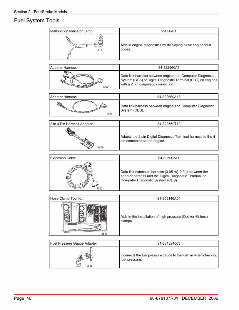
99056A1 MalfunctionIndicator Lamp X X
84‑822560A5 Adapter Harness X X X
84‑822560A13 Adapter Harness X
84‑822560T12 2 to 4 PinHarness Adapter X X X
84‑825003A1 Extension Cale X X X X X
91‑803146A04 Hose Clamp ToolKit X X X X X X X
91‑881824003 Fuel PressureGauge Adapter X
91‑881828Tamper‑ProofScrew Torx BitSet
X X X X X
91‑881833A03 Fuel PressureGauge Kit X X X X X X X
91‑881834A1Dual Fuel/AirPressure GaugeKit
X X X X X X X
91‑884793A1 Diagnostic Lamp X
91‑892647A01 DMT 2004 DigitalMultimeter X X X X X X X X X X
91‑892651A01 Digital PressureMeter X X X X X X X
Order throughSPX
ComputerDiagnosticSystem (CDS)
X X X X X X X X
Section 2 - FourStroke Models
Page 46 90-878107R01 DECEMBER 2006
Fuel System Tools
Malfunction Indicator Lamp 99056A 1
11777
Aids in engine diagnostics by displaying basic engine faultcodes.
Adapter Harness 84‑822560A5
4009
Data link harness between engine and Computer DiagnosticSystem (CDS) or Digital Diagnostic Terminal (DDT) on engineswith a 2 pin diagnostic connection.
Adapter Harness 84‑822560A13
5826
Data link harness between engine and Computer DiagnosticSystem (CDS).
2 to 4 Pin Harness Adapter 84‑822560T12
4679
Adapts the 2 pin Digital Diagnostic Terminal harness to the 4pin connector on the engine.
Extension Cable 84‑825003A1
4012
Data link extension harness (3.05 m[10 ft.]) between theadapter harness and the Digital Diagnostic Terminal orComputer Diagnostic System (CDS).
Hose Clamp Tool Kit 91‑803146A04
5819
Aids in the installation of high pressure (Oetiker ®) hoseclamps.
Fuel Pressure Gauge Adapter 91‑881824003
10868
Connects the fuel pressure gauge to the fuel rail when checkingfuel pressure.

Section 2 - FourStroke Models
90-878107R01 DECEMBER 2006 Page 47
Tamper‑Proof Screw Torx Bit Set 91‑881828
11782
Aids in the removal of tamper‑proof fasteners.
Fuel Pressure Gauge Kit 91‑881833A03
rms32
Tests the fuel pump pressure; can be used to relieve fuelpressure.
Dual Fuel/Air Pressure Gauge Kit 91‑881834A 1
5822
Tests fuel and air pressure; the dual gauges allow the viewingof both pressures simultaneously.
Diagnostic Lamp 91‑884793A 1
11780
Aids in engine diagnostics by displaying basic engine faultcodes.
DMT 2004 Digital Multimeter 91‑892647A01
A C O M m A V H z
mV
V
H z TEMPm A
A
IG
IPOFF
H z
TEMP
4516
Measures RPM on spark ignition (SI) engines, ohms, amperes,AC and DC voltages; records maximums and minimumssimultaneously, and accurately reads in high RFI environments.
Digital Pressure Meter 91‑892651A01
5786
Connects to the fuel system/manifold and can be used inconjunction with Computer Diagnostic System (CDS).

Section 2 - FourStroke Models
Page 48 90-878107R01 DECEMBER 2006
Computer Diagnostic System (CDS) Order through SPX
4520
Monitors all electrical systems for proper function, diagnostics,and calibration purposes. For additional information, pricing, orto order the Computer Diagnostic System contact:SPX Corporation28635 Mound Rd.Warren, MI 48092or call:USA ‑ 1‑800‑345‑2233Canada ‑ 800‑345‑2233Europe ‑ 49 6182 959 149Australia ‑ (03) 9544‑6222
PowerheadPowerhead Tool Application Chart
Part No. Description 4/5/68/9.99.9
BigFoot9.9/15 25
Bigfoot25/30EFI
30/40EFI
40‑60EFI 50/60 75/90 75/90
EFI115EFI
75‑115EFI
1.7 L
225EFI
N/A Cam Brake X
N/A CrankshaftRetainer X
N/ADial IndicatorExtensionAdapter
X
N/A RingCompressor X
N/A Rod GuideDowel X
22‑883147 AdapterFitting X X X X
91‑13662T1 PowerheadStand X
91‑24697 Piston RingExpander X X X X X X X X X X X X X
91‑802653Q02 Oil FilterWrench X X X X X X X X X
91‑803146A04 Hose ClampTool Kit X
91‑804770A1 CrankshaftHolder X X X
91‑804774001Valve GuideRemover/Installer
X X X
91‑804775 Valve GuideReamer X X X
91‑809494A1 Valve SpringCompressor X X X X X X X X X X X X
91‑809495A1 Valve GuideDriver X X X X X
91‑809496A1Valve GuideDriverBushing
X X X X X

Section 2 - FourStroke Models
90-878107R01 DECEMBER 2006 Page 49
Part No. Description 4/5/68/9.99.9
BigFoot9.9/15 25
Bigfoot25/30EFI
30/40EFI
40‑60EFI 50/60 75/90 75/90
EFI115EFI
75‑115EFI
1.7 L
225EFI
91‑809646A1 1‑5/8 Socket X
91‑80990500113 mmTorqueAdapter
X
91‑827001A1 PowerheadStand X X X X
91‑83163M FlywheelHolder X X X X X X X X X
91‑83164MFlywheelPuller/LiftingRing
X X X X X X X X X
91‑83165TBearingPullerAssembly
X X X X X X
91‑881833A03FuelPressureGauge Kit
X
91‑881834A1Dual Fuel/AirPressureGauge Kit
X X X X
91‑881847T 46 mmSocket X X X
91‑883705T01 Lifting Strap X
91‑889277002 Oil FilterWrench X
91‑889277Q01 Oil FilterWrench X
91‑892651A01DigitalPressureMeter
X X X X
91‑895191 CrankshaftHolding Tool X
91‑895192Piston RingCompressorTool
X
FT2997 Piston RingCompressor X X X X X X X X X X X X X
Powerhead Tools
Cam Brake Part number not available for this printing.
5539
Prevents the intake and exhaust cam from turning whileremoving or installing cam retaining bolts.

Section 2 - FourStroke Models
Page 50 90-878107R01 DECEMBER 2006
Crankshaft Retainer Part number not available for this printing.
6191
Secures crankshaft to cylinder block while rotating block toinstall the cylinder head.
Dial Indicator Extension Adapter Part number not available for this printing.
4719
Extends the dial indicators reach.
Ring Compressor Part number not available for this printing
4739
Compresses piston rings when installing the piston into thecylinder block.
Rod Guide Dowel Part number not available for this printing.
4735
Prevents cylinder bore and crankshaft from damage whileinstalling or removing connecting rod assembly.
Adapter Fitting 22‑883147
12201
Adapts British Standard Pipe Thread (BSPT) to National PipeThread Fitting (NPTF) when checking oil pressure.
Powerhead Stand 91‑13662T 1
13477
Used to secure and rotate the powerhead during disassemblyand assembly.
Piston Ring Expander 91‑24697
6255
Expands piston rings for removal and installation.
Oil Filter Wrench 91‑802653Q02
5221
Assists in removal of oil filter.

Section 2 - FourStroke Models
90-878107R01 DECEMBER 2006 Page 51
Hose Clamp Tool Kit 91‑803146A04
5819
Aids in the installation of high pressure (Oetiker ®) hoseclamps.
Crankshaft Holder 91‑804770A 1
12199
Holds crankshaft while servicing the powerhead.
Valve Guide Remover/Installer 91‑804774001
12195
Removes and installs valve guides.
Valve Guide Reamer 91‑804775
8869
Use to ream valve guides out to proper size.
Valve Spring Compressor 91‑809494A1
3454
Removes and installs valve springs.
Valve Guide Driver 91‑809495A 1
8867
Removes and installs valve guides.
Valve Guide Driver Bushing 91‑809496A 1
8868Limits depth of valve guide installation.
1‑5/8 Socket 91‑809646A1
13492
Aids in the removal of the crankshaft timing gear nut.
13 mm Torque Adapter 91‑809905001
4631
Aids in the removal and installation of powerhead nuts, andtorquing nuts to specification.

Section 2 - FourStroke Models
Page 52 90-878107R01 DECEMBER 2006
Powerhead Stand 91‑827001A 1
13494
Used to secure and rotate the powerhead during disassemblyand assembly.
Flywheel Holder 91‑83163M
8742
Holds and/or turns the flywheel while making engine repairs,also used to torque the flywheel or the engine coupler.
Flywheel Puller/Lifting Ring 91‑83164M
8744
Removes flywheel from engine. Used for lifting powerhead/engine.
Bearing Puller Assembly 91‑83165T
3610
Removes bearings, races and bearing carriers
Fuel Pressure Gauge Kit 91‑881833A03
rms32
Tests the fuel pump pressure; can be used to relieve fuelpressure.
Dual Fuel/Air Pressure Gauge Kit 91‑881834A 1
5822
Tests fuel and air pressure; the dual gauges allow the viewingof both pressures simultaneously.

Section 2 - FourStroke Models
90-878107R01 DECEMBER 2006 Page 53
46 mm Socket 91‑881847T
12200
Aids in the removal and torquing of the flywheel.
Lifting Strap 91‑883705T01
25496Aids in the removal and installation of the F225 engine.
Oil Filter Wrench 91‑889277002
5221
Aids in the removal of the oil filter.
Oil Filter Wrench 91‑889277Q01
5221
Aits in the removal of the oil filter.
Digital Pressure Meter 91‑892651A01
5786
Connects to the fuel system/manifold and can be used inconjunction with Computer Diagnostic System (CDS).
Crankshaft Holding Tool 91‑895191
3455
Holds crankshaft while servicing the powerhead.
Piston Ring Compressor Tool 91‑895192
3456
Compresses piston rings for easy piston installation.

Section 2 - FourStroke Models
Page 54 90-878107R01 DECEMBER 2006
Piston Ring Compressor FT2997
8745
Compresses the piston rings to ease piston installation.
Mid‑SectionMid Section Tool Application Chart
Part No. Description8/9.99.9
BigFoot9.9/15 25
BigFoot25/30EFI
30/40EFI
40‑60EFI 50/60 75/90 75/90
EFI115EFI
75‑115EFI
1.7 L
225EFI
91‑52915A6Power TrimTest GaugeKit
X X X X X X X X
91‑63209 Torch Lamp X X X X X X X X
91‑74951 SpannerWrench X X X X X X X X
91‑821709TTrimCylinder EndCap Tool
X X X X X X X X
91‑822778A1 AdapterFitting X X X
91‑822778A2 AdapterFitting X X X
91‑822778A 3 AdapterFitting X X X X X X X
91‑875215DriveshaftBushingInstaller Tool
X X X
91‑892647A01DMT 2004DigitalMultimeter
X X X X X X X X X X X X
91‑99750A 1DVA/MultimeterKit
X X X X X X X
Snap‑OnCG41‑11
ExpandingRod X X X X X X X X
Snap‑OnCG41‑14 Collet X X X X X X X
Snap‑On SRP‑2 Lock‑RingPliers X X
Snap‑On SRP‑4 Lock‑RingPliers X X X X X X X

Section 2 - FourStroke Models
90-878107R01 DECEMBER 2006 Page 55
Mid‑Section Tools
Power Trim Test Gauge Kit 91‑52915A6
3753
Tests circuit pressures for various trim pumps.
Torch Lamp 91‑63209
8776
Heats surfaces to aid in the removal and installation ofinterference fit engine components.
Spanner Wrench 91‑74951
8775
Removes and installs trim cylinder end caps.
Trim Cylinder End Cap Tool 91‑821709T
10691
Allows easy removal of the trim cylinder end caps. Required iftilt limit spacers are to be installed or if the trim in limit spaceris to be removed (to allow additional trim in range).
Adapter Fitting 91‑822778A 1
91 822778 1
12203
Measures the internal pressure in the up mode for a singlecylinder trim system.
Adapter Fitting 91‑822778A 2
91 822778 28637
Install in place of the manual release valve to measure theinternal pressure of the power trim pump in the up mode.
Adapter Fitting 91‑822778A 3
91 822778 38861
Install in place of the manual release valve to measure theinternal pressure of the power trim pump in the down mode.
Driveshaft Bushing Intaller Tool 91‑875215
12202Aids in the installation of driveshaft bushings.

Section 2 - FourStroke Models
Page 56 90-878107R01 DECEMBER 2006
DMT 2004 Digital Multimeter 91‑892647A01
A C O M m A V H z
mV
V
H z TEMPm A
A
IG
IPOFF
H z
TEMP
4516
Measures RPM on spark ignition (SI) engines, ohms, amperes,AC and DC voltages; records maximums and minimumssimultaneously, and accurately reads in high RFI environments.
DVA/Multimeter Kit 91‑99750A 1
3460
Tests the electrical and ignition systems; consists of a VOAmeter with built‑in direct voltage adapter.
Expanding Rod Snap‑On CG41‑11
8753Aids in the removal of the spool from the power trim pump.
Collet Snap‑On CG41‑14
8754
Aids in the removal of the spool from the power trim pump.
Lock‑Ring Pliers Snap‑On SRP2
8752
Removes and installs external snap rings and piston rings.
Lock‑Ring Pliers Snap‑On SRP‑4
4799
Aids in the removal of lock rings.
Lower UnitGear Housing Tool Application Chart
Part No. Description 4/5/68/9.99.9
Bigfoot9.9/15 25
Bigfoot25/30EFI
30/40EFI
40‑60EFI 50/60 75/90 75/90
EFI115EFI
75‑115EFI
1.7 L
225EFI
12‑34961 Washer X X X X

Section 2 - FourStroke Models
90-878107R01 DECEMBER 2006 Page 57
Part No. Description 4/5/68/9.99.9
Bigfoot9.9/15 25
Bigfoot25/30EFI
30/40EFI
40‑60EFI 50/60 75/90 75/90
EFI115EFI
75‑115EFI
1.7 L
225EFI
91‑12349A05Pinion GearLocatingTool
X X X X X X X
91‑13658T Mandrel X
91‑13945BearingInstallationDriver
X X X X X X X
91‑13949 Oil SealDriver X X X X X X X X
91‑14308T02 BearingRace Driver X X X X X X X X
91‑14309T02BearingInstallationPuller
X X X X X X X X
91‑14310T1WearSleeveDriver
X X X X X X X X
91‑14311A04 BearingPreload Tool X X X X X X X X
91‑15755TNeedleBearingDriver
X X X X X X X
91‑19660‑1 BacklashIndicator X X X X X X X X
91‑27780 Puller X X X X X X X
91‑29310 Puller Plate X
91‑31106T Bearing CupDriver X X X X X X X X
91‑31108T Oil SealDriver X X X X X X X X X
91‑31229A7
BearingRemovalandInstallationKit
X X X X X X X X X X
91‑34569A1 SlideHammer X X X X X X X X X X X X
91‑36569T Driver Head X X X X X X X
91‑36571T Pilot Washer X X X X
91‑37241 UniversalPuller Plate X X X X X X X X X X X X
91‑37312TDriveshaftBearingDriver Head
X X X X
91‑37323 Driver Rod X X X X X X X X X
91‑37350T PilotMandrel X X X X X X X X

Section 2 - FourStroke Models
Page 58 90-878107R01 DECEMBER 2006
Part No. Description 4/5/68/9.99.9
Bigfoot9.9/15 25
Bigfoot25/30EFI
30/40EFI
40‑60EFI 50/60 75/90 75/90
EFI115EFI
75‑115EFI
1.7 L
225EFI
91‑43506T
DriveshaftBearingReatinerWrench
X X
91‑46086A1 Puller JawsAssembly X X X X X X X X X
91‑56775T DriveshaftHolding Tool X X X X
91‑58222A1 DialIndicator X X X X X X X X X X X
91‑63209 Torch Lamp X X
91‑78473BacklashIndicatorRod
X X X X X X
91‑803133 12BacklashIndicatorArm
X X
91‑804762 DriveshaftHolding Tool X
91‑804776A1 DriveshaftHolding Tool X X X X X X
91‑817005
ForwardGearBearingInstaller
X X X
91‑817006Water PumpBase SealInstaller
X X X
91‑817007TBearingCarrier SealInstaller
X X X X
91‑817008A2Pinion GearLocationTool
X X X
91‑817009T
ForwardGearBearingRace DriverCup
X X X
91‑817011TNeedleBearingInstaller
X X X X
91‑817057A02BearingPreload ToolUpdate Kit
X X X
91‑817058A1
LowerDriveshaftBearingDriverAssembly
X X X
91‑817070 DriveshaftHolding Tool X X X X X

Section 2 - FourStroke Models
90-878107R01 DECEMBER 2006 Page 59
Part No. Description 4/5/68/9.99.9
Bigfoot9.9/15 25
Bigfoot25/30EFI
30/40EFI
40‑60EFI 50/60 75/90 75/90
EFI115EFI
75‑115EFI
1.7 L
225EFI
91‑824785T1Seal/BushingInstaller
X
91‑825198 Mandrel X
91‑825200A1 Spring Hook X X X
91‑826872 Driver X X
91‑83155DialIndicatorAdapter
X X X X X X X X X X
91‑83164MFlywheelPuller/LiftingRing
X
91‑83165TBearingPullerAssembly
X X X X X X X X X X X
91‑83166M BearingMandrel Kit X X
91‑853996‑6Spring PinRemovalTool
X
91‑853996 8 Spring PinDriver X
91‑853996 12 Pinion NutTool X
91‑853996 14 DriveshaftHolding Tool X
91‑856875A1 BearingDriver X X X X X X X
91‑86642‑1SlottedCross PinTool
X X X
91‑875215A1
DriveshaftBushingInstallationTool
91‑877321A1 BearingDriver X X X X X X
91‑877840A1 DriveshaftHolding Tool X X X
91‑888870(stamped06605)
Driver Rod X
91‑888875T PinionHeight Gage X
91‑888877 Shift Rod X
91‑888878BacklashIndicatorTool
X
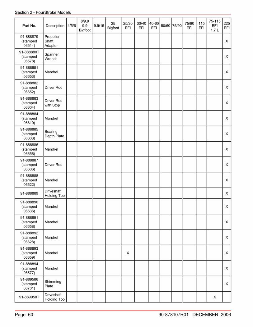
Section 2 - FourStroke Models
Page 60 90-878107R01 DECEMBER 2006
Part No. Description 4/5/68/9.99.9
Bigfoot9.9/15 25
Bigfoot25/30EFI
30/40EFI
40‑60EFI 50/60 75/90 75/90
EFI115EFI
75‑115EFI
1.7 L
225EFI
91‑888879(stamped06514)
PropellerShaftAdapter
X
91‑888880T(stamped06578)
SpannerWrench X
91‑888881(stamped06653)
Mandrel X
91‑888882(stamped06652)
Driver Rod X
91‑888883(stamped06604)
Driver Rodwith Stop X
91‑888884(stamped06610)
Mandrel X
91‑888885(stamped06603)
BearingDepth Plate X
91‑888886(stamped06656)
Mandrel X
91‑888887(stamped06606)
Driver Rod X
91‑888888(stamped06622)
Mandrel X
91‑888889 DriveshaftHolding Tool X
91‑888890(stamped06636)
Mandrel X
91‑888891(stamped06658)
Mandrel X
91‑888892(stamped06628)
Mandrel X
91‑888893(stamped06659)
Mandrel X X
91‑888894(stamped06577)
Mandrel X
91‑889586(stamped06701)
ShimmingPlate X
91‑889958T DriveshaftHolding Tool X

Section 2 - FourStroke Models
90-878107R01 DECEMBER 2006 Page 61
Part No. Description 4/5/68/9.99.9
Bigfoot9.9/15 25
Bigfoot25/30EFI
30/40EFI
40‑60EFI 50/60 75/90 75/90
EFI115EFI
75‑115EFI
1.7 L
225EFI
91‑895195 PinionBearing Tool X
91‑895195001BearingInstallationTool
X X
91‑895195004 BacklashPreload Tool X X
91‑895218 PinionHeight Tool X
FT8950 LeakageTester Kit X X X X
Snap‑OnCG40‑4
ExpandingRod X X
Snap‑OnCG40A‑6 Collet X X
Gear Housing Tools
Washer 12‑34961
10834
Use on the threaded puller rod between the nut and plate whenremoving bearings.
Pinion Gear Locating Tool 91‑12349A05
3608
Measures pinion gear height.
Mandrel 91‑13658T
13513
Aids in the installation of bushings, bearings and races into thegearcase.
Bearing Installation Driver 91‑13945
8877
Installs reverse gear needle bearing into prop shaft carrier.

Section 2 - FourStroke Models
Page 62 90-878107R01 DECEMBER 2006
Oil Seal Driver 91‑13949
8878
Installs oil seals into water pump base.
Bearing Race Driver 91‑14308T02
8879
Removes pinion bearing race.
Bearing Installation Puller 91‑14309T02
8880Installs pinion bearing into gearcase.
Wear Sleeve Driver 91‑14310T 1
8881Installs wear sleeve onto driveshaft.
Bearing Preload Tool 91‑14311A04
8756
Simulates a load on the driveshaft for accurate pinion heightand backlash measurements.
Needle Bearing Driver 91‑15755T
10787
Installs needle bearings into bearing carriers.
Backlash Indicator 91‑19660‑‑1
8757
Measures gear backlash.
Puller 91‑27780
8760
Removes gears, bearings and races.

Section 2 - FourStroke Models
90-878107R01 DECEMBER 2006 Page 63
Puller Plate 91‑29310
18600
Aids in the removal and installation of the gimbal bearing, aswell as various bearings in the gear housing. Also included inthe Bearing Removal and Installation Kit (91‑31229A 7).
Bearing Cup Driver 91‑31106T
3 1 1 0 6
8882
Installs the driven gear bearing cup.
Oil Seal Driver 91‑31108T
8883
Installs bearing carrier oil seals.
Bearing Removal and Installation Kit 91‑31229A7
2966
Installs and removes the bearings in all gearcases.91‑31229A7 tool assembly includes the following components:11‑24156 Hex Nut12‑34961 Washer91‑15755T Bearing Carrier91‑29310 Plate91‑29610 Pilot Plate91‑30366T1 Mandrel91‑31229 Puller Shaft91‑32325T Driver Head91‑32336 Driver Needle Bearing91‑36379 Puller/Head Gear91‑36569T Driver Head91‑36571T Pilot Washer91‑37292 Roller Bearing91‑37311 Driver Head91‑37312 ‑Driver Head91‑37323 Driver Head Rod91‑37324 Pilot Washer91‑38628T Puller/Driver Head91‑52393 Driver Needle Bearing91‑52394 Head Pull Rod
Slide Hammer 91‑34569A 1
6761
Aids in the removal of various engine components. Use withpuller jaws.
Driver Head 91‑36569T
ob01634
Used in pinion gear and bearing installation.

Section 2 - FourStroke Models
Page 64 90-878107R01 DECEMBER 2006
Pilot Washer 91‑36571T
ob01619
Used in pinion gear and pinion bearing installation.
Universal Puller Plate 91‑37241
8505
Removes bearings from gears and the driveshaft.
Driveshaft Bearing Driver Head 91‑37312T
8762
Removes bearings from gears and bearing carrier.
Driver Rod 91‑37323
25431 Used in pinion gear and pinion bearing installation.
Pilot Mandrel 91‑37350T
8884
Presses on inner race of forward gear roller bearing.
Driveshaft Bearing Retainer Wrench 91‑43506T
9520
Removes and installs the threaded bearing retainer.
Puller Jaws Assembly 91‑46086A1
9514
Removes bearing carrier and bearing races; use with Puller Bolt(91‑85716).
Driveshaft Holding Tool 91‑56775T
9448
Provides a wrench surface to turn the driveshaft. Also used tohold driveshaft for pinion gear installation.

Section 2 - FourStroke Models
90-878107R01 DECEMBER 2006 Page 65
Dial Indicator 91‑58222A1
010
20 30
4050
60
7080
90
9479
Used to obtain a variety of measurements including gearbacklash, pinion gear location, and TDC.
Torch Lamp 91‑63209
8776
Heats surfaces to aid in the removal and installation ofinterference fit engine components.
Backlash Indicator Rod 91‑78473
9450
Aids in checking gear backlash.
Backlash Indicator Arm 91‑803133 12
12512
Aids in determining the forward gear backlash; use with a dialindicator.
Driveshaft Holding Tool 91‑804762
12519
Holds the driveshaft while removing or installing the pinion gearnut.
Driveshaft Holding Tool 91‑804776A1
12376
Holds driveshaft while removing or torquing the pinion nut.
Forward Gear Bearing Installer 91‑817005
8763
Aids in the installation of the forward gear needle bearing.
Water Pump Base Seal Installer 91‑817006
8767
Installs upper and lower water pump base seals.

Section 2 - FourStroke Models
Page 66 90-878107R01 DECEMBER 2006
Bearing Carrier Seal Installer 91‑817007T
8768
Installs upper and lower bearing carrier seals.
Pinion Gear Location Tool 91‑817008A 2
8769
Checks gearcase pinion gear height.
Forward Gear Bearing Race Driver Cup 91‑817009T
8771
Aids in the installation of forward gear bearing race.
Needle Bearing Installer 91‑817011T
8772
Installs needle bearing in the bearing carrier.
Bearing Preload Tool Update Kit 91‑817057A02
8773
Use to update Bearing Preload Tool (91‑14311A1).

Section 2 - FourStroke Models
90-878107R01 DECEMBER 2006 Page 67
Lower Driveshaft Bearing Driver Assembly 91‑817058A 1
8778
Removes and installs lower driveshaft bearing.
Driveshaft Holding Tool 91‑817070
8779
Holds driveshaft while removing pinion nut.
Seal/Bushing Installer 91‑824785T 1
13507
Aids in the installation of the bushing into the bearing carrier.
Mandrel 91‑825198
25406
Aids in the installation of the bearing carrier oil seals.
Spring Hook 91‑825200A 1
13666
Aids in the removal of the pinion bearing race from thegearcase; use with driver (91‑13779).
Driver 91‑826872
13667
Aids in the installation of the propeller shaft needle bearing intothe forward gear.

Section 2 - FourStroke Models
Page 68 90-878107R01 DECEMBER 2006
Dial Indicator Adapter 91‑83155
2999
Attaches the dial indicator to the gearcase when checkingbacklash.
Flywheel Puller/Lifting Ring 91‑83164M
8744
Removes flywheel from engine. Used for lifting powerhead/engine.
Bearing Puller Assembly 91‑83165T
3610
Removes bearings, races and bearing carriers
Bearing Mandrel Kit 91‑83166M
3421
Aids in the removal and installation of bearings and bearingraces.
Spring Pin Removal Tool 91‑853996‑6
3423Aids in the removal of the spring pins.
Spring Pin Driver 91‑853996 8
3422Aids in the installation of the shift cam spring pin.
Pinion Nut Tool 91‑853996 12
17189
Removes the pinion nut; aids in the installation of the driveshaftbearing.

Section 2 - FourStroke Models
90-878107R01 DECEMBER 2006 Page 69
Driveshaft Holding Tool 91‑853996 14
17174
Holds the driveshaft while removing or installing the pinion gearnut.
Bearing Driver 91‑856875A 1
8885
Installs prop shaft needle bearing into 3 jaw or 6 jaw forwardgear.
Slotted Cross Pin Tool 91‑86642‑‑1
9895Assists in clutch assembly/disassembly.
Driveshaft Bushing Installation Tool 91‑875215A1
12359Installs the driveshaft bushing.
Bearing Driver 91‑877321A 1
8886
Installs prop shaft needle bearing into 6 jaw forward gear.
Driveshaft Holding Tool 91‑877840A 1
8780
Holds driveshaft while removing pinion nut.
Driver Rod (stamped 06605) 91‑888870
0660525409
Aids in the removal and installation of bearings; used withvarious mandrels.
Pinion Height Gauge 91‑888875T
25410
Measures the gear housing length when installing pinion gearshims.

Section 2 - FourStroke Models
Page 70 90-878107R01 DECEMBER 2006
Shift Rod 91‑888877
25411
Aids in shifting the gearcase while performing various serviceprocedures.
Backlash Indicator Tool 91‑888878
25408
Aids in checking gear backlash.
Propeller Shaft Adapter (stamped 06514) 91‑888879
25441
Attaches to the propeller shaft for use with a slide hammer.
Spanner Wrench (stamped 06578) 91‑888880T
25443
06578 Removes and installs the bearing carrier retainer nut.
Mandrel (stamped 06653) 91‑888881
0665325414
Aids in the removal of the bearing carrier oil seals. Also used toinstall bearings into the reverse gear assembly.
Driver Rod (stamped 06652) 91‑888882
0665225418
Aids in the removal and installation of bearings; used withvarious mandrels.
Driver Rod with Stop (stamped 06604) 91‑888883
06604 25419
Aids in setting the bearing depth; used with a mandrel.
Mandrel (stamped 06610) 91‑888884
06610
25420
Aids in the removal and installation of various bearings and oilseals in the bearing carrier.

Section 2 - FourStroke Models
90-878107R01 DECEMBER 2006 Page 71
Bearing Depth Plate (stamped 06603) 91‑888885
06603
25421
Shimming gauge for reverse gear assembly.
Mandrel (stamped 06656) 91‑888886
0665625422
Aids in the installation of the propeller shaft bearings into thebearing carrier.
Driver Rod (stamped 06606) 91‑888887
0660625423
Aids in the removal and installation of bearings; used withvarious mandrels.
Mandrel (stamped 06622) 91‑888888
0662225424
Aids in the installation of the reverse gear into the bearingcarrier.
Driveshaft Holding Tool 91‑888889
25425
Provides a wrench surface to rotate the driveshaft. Also usedto hold the driveshaft for pinion gear installation.
Mandrel (stamped 06636) 91‑888890
0663625426
Aids in the removal of the driveshaft needle bearings in thegearcase.
Mandrel (stamped 06658) 91‑888891
06658
25427
Aids in the installation of the reverse gear bearing.
Mandrel (stamped 06628) 91‑888892
0662825428
Aids in the installation of bearings and oil seals into the bearingcarrier and gearcase.

Section 2 - FourStroke Models
Page 72 90-878107R01 DECEMBER 2006
Mandrel (stamped 06659) 91‑888893
06659 25429
Aids in the installation of the tapered roller bearing onto theforward gear.
Mandrel (stamped 06657) 91‑888894
06657
25444
Aids in the removal and installation of various bearings andseals.
Shimming Plate (stamped 06701) 91‑889586
06701
25407
Fixture used to shim the forward gear.
Driveshaft Holding Tool 91‑889958T
ob01206
Holds driveshaft during pinion nut removal on the Veradomodels.
Pinion Bearing Tool 91‑895195
3777
Guides the removal and installation of the pinion bearing.
Bearing Installation Tool 91‑895195001
12528
Aids in the installation of bearings into the gearcase.
Backlash Preload Tool 91‑895195004
12520
Prevents forward gear movement when checking the forwardgear backlash.
Pinion Height Tool 91‑895218
17369
Aids in determining the pinion gear height.

Section 2 - FourStroke Models
90-878107R01 DECEMBER 2006 Page 73
Leakage Tester Kit FT8950
ob01632
Checks gear housing for leakage prior to filling with gearlubricant. Also used to pressurize the oil injection system.
Expanding Rod Snap‑On CG40‑4
12538Aids in the removal of gears and bearings; use with collet.
Collet Snap‑On CG40A‑6
12534
Aids in the removal of gears or bearings; use with expandingrod.

Section 2 - FourStroke Models
Notes:
Page 74 90-878107R01 DECEMBER 2006

Section 3 - OptiMax Models
90-878107R01 DECEMBER 2006 Page 75
Section 3 - OptiMax ModelsTable of ContentsInstallation and Maintenance.............................. 76
Maintenance Tool Application Chart.............76Maintenance Tools........................................76
Electrical and Ignition.......................................... 77Electrical Tool Application Chart...................77Electrical Tools..............................................77
Fuel System........................................................ 79Fuel System Tool Application Chart..............79Fuel System Tools........................................80
Powerhead.......................................................... 82Powerhead Tool Application Chart................82Powerhead Tools..........................................83
Mid-Section......................................................... 85Mid-Section Tool Application Chart...............85Mid-Section Tools.........................................86
Lower Unit........................................................... 87Gear Housing Tool Application Chart............87Gear Housing Tools......................................90
3

Section 3 - OptiMax Models
Page 76 90-878107R01 DECEMBER 2006
Installation and MaintenanceMaintenance Tool Application Chart
Part No. Description 75/90/115OptiMax DFI
115/135/150/175OptiMax DFI
200 OptiMax JetDrive
200/225OptiMax DFI
225/250 Pro XSOptiMax
44357Q2 Flushing Device X X X X
881150K1Dual Water
Pick‑Up FlushGearcase Seal Kit
X X
91‑37299Q2 Grease Gun X X X X X
91‑90455‑1 Lifting Eye X X X
91‑98234A2 Transom DrillingFixture X X
Maintenance Tools
Flushing Device 44357Q 2
9192
Attaches to the water intakes; provides a fresh waterconnection when flushing the cooling system or operating theengine.
Dual Water Pick‑up Flush Gearcase Seal Kit 881150K 1
9194
Blocks off the front water inlet holes on the dual water inletgearcases.
Grease Gun 91‑37299Q 2
8120
Aids in the lubrication of key areas on the engine. Allows easyaccess to grease fittings.
Lifting Eye 91‑90455‑‑1
2756
Threads into the flywheel to remove the powerhead assemblyfrom the driveshaft housing, or to lift entire engine for removal/installation.

Section 3 - OptiMax Models
90-878107R01 DECEMBER 2006 Page 77
Transom Drilling Fixture 91‑98234A2
5489
Aids in engine installation by acting as a template for enginemounting holes.
Electrical and IgnitionElectrical Tool Application Chart
Part No. Description 75/90/115OptiMax DFI
115/135/150/175OptiMax DFI
200 OptiMaxJet Drive
200/225OptiMax DFI
225/250 ProXS OptiMax
84‑822560A5 Adapter Harness X X X X X
84‑822560T12 2 to 4 Pin HarnessAdapter X X X X
84‑825003A1 Extension Cable X X X X X
91‑24161 Protector Cap X X X X
91‑52344 Flywheel HoldingTool X X X X X
91‑802650 1 Clamp‑on CurrentProbe X X X X X
91‑849154T1 Flywheel Puller X X X X X
91‑850439T1 Spark Gap Tester X X X X
91‑892647A01 DMT 2004 DigitalMultimeter X X X X X
91‑99379 Timing Light X X X X
91‑99750A1 DVA/MulitmeterKit X X X X
Order Through SPXComputerDiagnostic
System (CDS)X X X X X
Electrical Tools
Adapter Harness 84‑822560A5
4009
Data link harness between engine and Computer DiagnosticSystem (CDS) or Digital Diagnostic Terminal (DDT) on engineswith a 2 pin diagnostic connection.
2 to 4 Pin Harness Adapter 84‑822560T12
4679
Adapts the 2 pin Digital Diagnostic Terminal harness to the 4pin connector on the engine.

Section 3 - OptiMax Models
Page 78 90-878107R01 DECEMBER 2006
Extension Cable 84‑825003A1
4012
Data link extension harness (3.05 m[10 ft.]) between adapterharness and Digital Diagnostic Terminal
Protector Cap 91‑24161
13445
Protects the crankshaft when removing the flywheel; use withflywheel puller (91‑849154T 1)
Flywheel Holding Tool 91‑52344
4738
Holds and/or turns the flywheel while making engine repairs,also used to torque the flywheel or the engine coupler.
Clamp‑on Current Probe 91‑802650‑1
4006
Measures the current output of battery charging systems orcurrent draw of electric motors.
Flywheel Puller 91‑849154T 1
7617
Removes the flywheel from the crankshaft.
Spark Gap Tester 91‑850439T 1
7513
Provides a visual indication of spark/coil efficiency.
DMT 2004 Digital Multimeter 91‑892647A01
A C O M m A V H z
mV
V
H z TEMPm A
A
IG
IPOFF
H z
TEMP
4516
Measures RPM on spark ignition (SI) engines, ohms, amperes,AC and DC voltages; records maximums and minimumssimultaneously, and accurately reads in high RFI environments.
Timing Light 91‑99379
11561
Allows a technician to check ignition timing.

Section 3 - OptiMax Models
90-878107R01 DECEMBER 2006 Page 79
DVA/Multimeter Kit 91‑99750A 1
3460
Tests the electrical and ignition systems; consists of a VOAmeter with built‑in direct voltage adapter.
Computer Diagnostic System (CDS) Order through SPX
4520
Monitors all electrical systems for proper function, diagnostics,and calibration purposes. For additional information, pricing, orto order the Computer Diagnostic System contact:SPX Corporation28635 Mound Rd.Warren, MI 48092or call:USA ‑ 1‑800‑345‑2233Canada ‑ 800‑345‑2233Europe ‑ 49 6182 959 149Australia ‑ (03) 9544‑6222
Fuel SystemFuel System Tool Application Chart
Part No. Description 75/90/115OptiMax DFI
115/135/150/175OptiMax DFI
200 OptiMaxJet Drive
200/225OptiMax DFI
225/250 ProXS OptiMax
22‑849606 Schrader ValveTree X X X X X
91‑803146A04 Hose Clamp ToolKit X X X X X
91‑804063 Tubing Clamp X X X X X
91‑851980‑2 Seal/Teflon RingSizing Tool X X X X X
91‑851980‑3 Seal/Teflon RingInstallation Tool X X X X X
91‑881833A03 Fuel PressureGauge Kit X X X X
91‑881834A1Duel Fuel/Air
Pressure GaugeKit
X X X X X
91‑883521 Direct InjectorRemoval Tool X X X X X
91‑889431 Air RegulatorInstallation Tool X X X X
91‑892647A01 DMT 2004 DigitalMultimeter X X X X X
91‑892651A01 Digital PressureMeter X X X X X
91‑99750A1 DVA/MiltimeterKit X X X X

Section 3 - OptiMax Models
Page 80 90-878107R01 DECEMBER 2006
Part No. Description 75/90/115OptiMax DFI
115/135/150/175OptiMax DFI
200 OptiMaxJet Drive
200/225OptiMax DFI
225/250 ProXS OptiMax
FT8950 Leakage TesterKit X X X X X
Order through SPXComputerDiagnostic
System (CDS)X X X X X
Fuel System Tools
Schrader Valve Tee 22‑849606
13678
Aids in checking fuel pressure when using a fuel pressuregauge with a screw on schrader valve connector.
Hose Clamp Tool Kit 91‑803146A04
5819
Aids in the installation of high pressure (Oetiker ®) hoseclamps.
Tubing Clamp 91‑804063
13688
Compresses a fuel or vacuum hose for troubleshooting the fuelsystem or synchronizing a multiple carburetor engine.
Seal/Teflon Ring Sizing Tool 91‑851980‑‑2
8286
Compresses the Teflon seal on direct injectors after sealinstallation.
Seal/Teflon Ring Installation Tool 91‑851980‑‑3
8285Aids in the installation of Teflon seals on direct injectors.
Fuel Pressure Gauge Kit 91‑881833A03
rms32
Tests the fuel pump pressure; can be used to relieve fuelpressure.

Section 3 - OptiMax Models
90-878107R01 DECEMBER 2006 Page 81
Dual Fuel/Air Pressure Gauge Kit 91‑881834A 1
5822
Tests fuel and air pressure; the dual gauges allow the viewingof both pressures simultaneously.
Direct Injector Removal Tool 91‑883521
8290
Aids in the removal of direct injectors from the fuel rail.
Air Regulator Installation Tool 91‑889431
8291
Compresses the air regulator spring to allow installation ofassembly screws.
DMT 2004 Digital Multimeter 91‑892647A01
A C O M m A V H z
mV
V
H z TEMPm A
A
IG
IPOFF
H z
TEMP
4516
Measures RPM on spark ignition (SI) engines, ohms, amperes,AC and DC voltages; records maximums and minimumssimultaneously, and accurately reads in high RFI environments.
Digital Pressure Meter 91‑892651A01
5786
Connects to the fuel system/manifold and can be used inconjunction with Computer Diagnostic System (CDS).
DVA/Multimeter Kit 91‑99750A 1
3460
Tests the electrical and ignition systems; consists of a VOAmeter with built‑in direct voltage adapter.

Section 3 - OptiMax Models
Page 82 90-878107R01 DECEMBER 2006
Leakage Tester Kit FT8950
ob01632
Checks gear housing for leakage prior to filling with gearlubricant. Also used to pressurize the oil injection system.
Computer Diagnostic System (CDS) Order through SPX
4520
Monitors all electrical systems for proper function, diagnostics,and calibration purposes. For additional information, pricing, orto order the Computer Diagnostic System contact:SPX Corporation28635 Mound Rd.Warren, MI 48092or call:USA ‑ 1‑800‑345‑2233Canada ‑ 800‑345‑2233Europe ‑ 49 6182 959 149Australia ‑ (03) 9544‑6222
PowerheadPowerhead Tool Application Chart
Part No. Description 75/90/115OptiMax DFI
115/135/150/175OptiMax DFI
200 OptiMaxJet Drive
200/225OptiMax DFI
225/250 ProXS OptiMax
91‑24161 Protector Cap X
91‑24697 Piston RingExpander X X X X X
91‑30591T1 Powerhead Stand X X X X
91‑37241 Universal PullerPlate X X X X X
91‑52024A1 Remote StarterSwitch X X X X X
91‑52344 Flywheel HoldingTool X X X X X
91‑52952T1 Lockring RemovalTool X X X X X
91‑74607A3 Piston Pin Tool X X
91‑77109A3 LockringInstallation Tool X X
91‑79250A2 Water PressureGauge X X X X X
91‑812549T Powerhead Stand X
91‑818773T Piston RingCompressor X X
91‑823237T Piston RingCompressor X X X
91‑849154T1 Flywheel Puller X X X X X
91‑883521 Direct InjectorRemoval Tool X
91‑90455‑1 Lifting Eye X X X X X

Section 3 - OptiMax Models
90-878107R01 DECEMBER 2006 Page 83
Part No. Description 75/90/115OptiMax DFI
115/135/150/175OptiMax DFI
200 OptiMaxJet Drive
200/225OptiMax DFI
225/250 ProXS OptiMax
91‑92973A1 Piston Pin Tool X X X X
91‑93004A2 LockringInstallation Tool X X X
Snap‑OnEEPV303B
CompressionTester with Adapter X X X
Powerhead Tools
Protector Cap 91‑24161
13445
Protects the crankshaft when removing the flywheel; use withflywheel puller (91‑849154T 1)
Piston Ring Expander 91‑24697
6255
Expands piston rings for removal and installation.
Powerhead Stand 91‑30591T 1
8493
Used to secure and rotate the powerhead during disassemblyand assembly.
Universal Puller Plate 91‑37241
8505
Removes bearings from gears and the driveshaft.
Remote Starter Switch 91‑52024A1
10882
Provides a remote starter button to crank the engine whenperforming service procedures.
Flywheel Holding Tool 91‑52344
4738
Holds and/or turns the flywheel while making engine repairs,also used to torque the flywheel or the engine coupler.
Lockring Removal Tool 91‑52952T 1
8500Removes the lockrings securing the piston wrist pin.

Section 3 - OptiMax Models
Page 84 90-878107R01 DECEMBER 2006
Piston Pin Tool 91‑74607A3
20637
Aids in the removal and installation of the piston wrist pin.
Lockring Installation Tool 91‑77109A3
8527Installs the lockrings to secure the piston wrist pin in piston.
Water Pressure Gauge 91‑79250A 2
0
5
1015
20
25
30
11598
Aids in checking the engine water pressure.
Powerhead Stand 91‑812549T
8493
Used to secure and rotate the powerhead during disassemblyand assembly.
Piston Ring Compressor 91‑818773T
4739
Compresses piston rings into piston ring grooves to ease pistonrod assembly into cylinder block.
Piston Ring Compressor 91‑823237T
4739
Compresses piston rings into piston ring grooves to ease pistonrod assembly into cylinder block.
Flywheel Puller 91‑849154T 1
7617
Removes the flywheel from the crankshaft.
Direct Injector Removal Tool 91‑883521
8290
Aids in the removal of direct injectors from the fuel rail.

Section 3 - OptiMax Models
90-878107R01 DECEMBER 2006 Page 85
Lifting Eye 91‑90455‑‑1
2756
Threads into the flywheel to remove the powerhead assemblyfrom the driveshaft housing, or to lift entire engine for removal/installation.
Piston Pin Tool 91‑92973A 1
11564
Aids in the removal and installation of the piston pins.
Lockring Installation Tool 91‑93004A 2
8527Installs the lockrings to secure the piston wrist pin in piston.
Compression Tester with Adapter Snap‑On EEPV303B
8511
Checks cylinder compression. Use with M14 x 1.25 adapter.
Mid‑SectionMid‑Section Tool Application Chart
Part No. Description 75/90/115 OptiMaxDFI
115/135/150/175 OptiMaxDFI
200/225 OptiMaxDFI
225/250 Pro XSOptiMax
91‑11230‑1 Alignment Tool X X X
91‑44486A1 Trim Rod RemovalTool X X X
91‑44487T1 Trim Rod GuideRemoval Tool X X X
91‑52915A6 Power Trim TestGauge Kit X X X X
91‑63209 Torch Lamp X X X X
91‑74951 Spanner Wrench X X X X
91‑822778A1 Adapter Fitting X
91‑822778A2 Adapter Fitting X X X
91‑822778A3 Adapter Fitting X X X X
91‑875215 Driveshaft BushingInstaller Tool X
91‑892647A01 DMT 2004 DigitalMultimeter X
91‑99750A1 DVA/MultimeterTester X X X
Snap‑On CG41‑11 Expanding Rod X
Snap‑On CG41‑12 Collet X
Snap‑On SRP‑4 Lock Ring Pliers X X X

Section 3 - OptiMax Models
Page 86 90-878107R01 DECEMBER 2006
Mid‑Section Tools
Alignment Tool 91‑11230‑‑1
9078Aligns the tilt ram with housing to aid installation of the pivot pin.
Trim Rod Removal Tool 91‑44486A 1
9089
Aids in the removal of the trim rod from the trim cylinders.
Trim Rod Guide Removal Tool 91‑44487T 1
9086
Aids in the removal of the trim rod from the trim cylinders.
Power Trim Test Gauge Kit 91‑52915A6
3753
Tests circuit pressures for various trim pumps.
Torch Lamp 91‑63209
8776
Heats surfaces to aid in the removal and installation ofinterference fit engine components.
Spanner Wrench 91‑74951
8775
Removes and installs trim cylinder end caps.
Adapter Fitting 91‑822778A 1
91 822778 1
12203
Measures the internal pressure in the up mode for a singlecylinder trim system.
Adapter Fitting 91‑822778A 2
91 822778 28637
Install in place of the manual release valve to measure theinternal pressure of the power trim pump in the up mode.

Section 3 - OptiMax Models
90-878107R01 DECEMBER 2006 Page 87
Adapter Fitting 91‑822778A 3
91 822778 38861
Install in place of the manual release valve to measure theinternal pressure of the power trim pump in the down mode.
Driveshaft Bushing Installer Tool 91‑875215
12202Aids in the installation of driveshaft bushings.
DMT 2004 Digital Multimeter 91‑892647A01
A C O M m A V H z
mV
V
H z TEMPm A
A
IG
IPOFF
H z
TEMP
4516
Measures RPM on spark ignition (SI) engines, ohms, amperes,AC and DC voltages; records maximums and minimumssimultaneously, and accurately reads in high RFI environments.
DVA/Multimeter Kit 91‑99750A 1
3460
Tests the electrical and ignition systems; consists of a VOAmeter with built‑in direct voltage adapter.
Expanding Rod Snap‑On CG41‑11
8753Aids in the removal of the spool from the power trim pump.
Collet Snap‑On CG41‑12
25498
Aids in the removal of internal components in the power trimvalve; use with an expanding rod.
Lock‑Ring Pliers Snap‑On SRP‑4
4799
Aids in the removal of lock rings.
Lower UnitGear Housing Tool Application Chart
Part Number Description 75/90/115OptiMax
115/135/150/175OptiMax
200 OptiMaxJet Drive
200/225OptiMax
225/250 Pro XSOptiMax
12‑34961 Washer X
12‑37429 Load Washer X X
12‑54048 Belleville Washer X

Section 3 - OptiMax Models
Page 88 90-878107R01 DECEMBER 2006
Part Number Description 75/90/115OptiMax
115/135/150/175OptiMax
200 OptiMaxJet Drive
200/225OptiMax
225/250 Pro XSOptiMax
44‑93003 Propeller Shaft Tool X X
91‑12349A05 Pinion GearLocating Tool X X X X
91‑13945 Bearing InstallationDriver X
91‑13949 Oil Seal Driver X
91‑14308T02 Bearing RaceDriver X
91‑14309T02 Bearing InstallationPuller X
91‑14310T1 Wear Sleeve Driver X
91‑14311A04 Bearing PreloadTool X X X X
91‑15755T Needle BearingDriver X X X
91‑18605A2Bearing Cup/Adapter InstallationTool
X X X
91‑19660‑1 Backlash Indicator X
91‑31106T Bearing Cup Driver X X X
91‑31107T Shift Shaft BushingTool X
91‑31108T Oil Seal Driver X X X
91‑31229A7 Bearing Removaland Installation Kit X X X X
91‑33491 Needle BearingDriver X
91‑34569A1 Slide Hammer X X X X X
91‑36569T Driver Head X X X
91‑36571T Pilot Washer X X X
91‑37241 Universal PullerPlate X X X X
91‑37323 Driver Rod X X X X
91‑37350T Pilot Mandrel X
91‑38628T Puller/Driver Head X X X
91‑43506T Driveshaft BearingRetainer Wrench X X X
91‑46086A1 Puller JawsAssembly X X X X
91‑53459 Backlash IndicatorRod X X X
91‑56775T Driveshaft HoldingTool X X X
91‑58222A1 Dial Indicator X X X X X
91‑61067A04 Pinion Nut Wrench X X

Section 3 - OptiMax Models
90-878107R01 DECEMBER 2006 Page 89
Part Number Description 75/90/115OptiMax
115/135/150/175OptiMax
200 OptiMaxJet Drive
200/225OptiMax
225/250 Pro XSOptiMax
91‑61069TBearing CarrierRetainer NutWrench
X X
91‑61077T Propeller Shaft/Driveshaft Adapter X
91‑66274 TorqueWrench,lb.in X
91‑74776T Pinion Height Tool X
91‑78473 Backlash IndicatorRod X X X
91‑809957A1 Jet Pump Tool Kit X
91‑815850 Forward GearAssembly Tube X X
91‑816242 Puller Jaws X
91‑816243 Guide Plate X
91‑816244Reverse GearNeedle BearingDriver
X
91‑816245 Needle BearingRemoval Tool X
91‑816292 Needle BearingDriver X
91‑817569T Carrier Seal Driver X X
91‑821571A1 Water PumpAlignment Pins X X
91‑83155 Dial IndicatorAdapter X X X X
91‑83165T Bearing PullerAssembly X
91‑840388 Bearing CarrierInstallation Tool X
91‑840393Bearing CarrierRetainer NutWrench
X
91‑856875A1 Bearing Driver X
91‑86642 Cross Pin Tool X
91‑86642‑2Cross Pin(T‑Handle)Installation Tool
X
91‑86943T Guide Plate X X
91‑87120T Bearing Cup Driver X
91‑877321A1 Bearing Driver X X
91‑89897 Dial IndicatorHolding Tool X X
91‑90094 Driveshaft HoldingTool X
91‑92788T Pinion BearingDriver X X

Section 3 - OptiMax Models
Page 90 90-878107R01 DECEMBER 2006
Part Number Description 75/90/115OptiMax
115/135/150/175OptiMax
200 OptiMaxJet Drive
200/225OptiMax
225/250 Pro XSOptiMax
FT8950 Leakage Tester Kit X X
Gear Housing Tools
Washer 12‑34961
10834
Use on the threaded puller rod between the nut and plate whenremoving bearings.
Load Washer 12‑37429
ob01619
Creates a load on the forward gear when taking forward gearbacklash measurements for counter rotation gearcases.
Belleville Washer 12‑54048
10772
Use with the Pinion Nut Adaptor (91‑61067A3) and a propellernut to check the reverse gear backlash.
Propeller Shaft Tool 44‑93003
11573
Acts as a dummy propeller shaft when taking forward gearbacklash measurements for counter rotation gearcases.
Pinion Gear Locating Tool 91‑12349A05
3608
Measures pinion gear height.
Bearing Installation Driver 91‑13945
8877
Installs reverse gear needle bearing into prop shaft carrier.

Section 3 - OptiMax Models
90-878107R01 DECEMBER 2006 Page 91
Oil Seal Driver 91‑13949
8878
Installs oil seals into water pump base.
Bearing Race Driver 91‑14308T02
8879
Removes pinion bearing race.
Bearing Installation Puller 91‑14309T02
8880Installs pinion bearing into gearcase.
Wear Sleeve Driver 91‑14310T 1
8881Installs wear sleeve onto driveshaft.
Bearing Preload Tool 91‑14311A04
8756
Simulates a load on the driveshaft for accurate pinion heightand backlash measurements.
Needle Bearing Driver 91‑15755T
10787
Installs needle bearings into bearing carriers.
Bearing Cup/Adapter Installation Tool 91‑18605A 2
9591
Installs the forward gear bearing race on a standard gearcase.Presses the reverse gear bearing adapter into the gear housingon a counter rotating gearcase.
Backlash Indicator 91‑19660‑‑1
8757
Measures gear backlash.

Section 3 - OptiMax Models
Page 92 90-878107R01 DECEMBER 2006
Bearing Cup Driver 91‑31106T
3 1 1 0 6
8882
Installs the driven gear bearing cup.
Shift Shaft Bushing Tool 91‑31107T
9906
Aids in the removal and installation of the shift shaft bushing.
Oil Seal Driver 91‑31108T
8883
Installs bearing carrier oil seals.
Bearing Removal and Installation Kit 91‑31229A7
2966
Installs and removes the bearings in all gearcases.91‑31229A7 tool assembly includes the following components:11‑24156 Hex Nut12‑34961 Washer91‑15755T Bearing Carrier91‑29310 Plate91‑29610 Pilot Plate91‑30366T1 Mandrel91‑31229 Puller Shaft91‑32325T Driver Head91‑32336 Driver Needle Bearing91‑36379 Puller/Head Gear91‑36569T Driver Head91‑36571T Pilot Washer91‑37292 Roller Bearing91‑37311 Driver Head91‑37312 ‑Driver Head91‑37323 Driver Head Rod91‑37324 Pilot Washer91‑38628T Puller/Driver Head91‑52393 Driver Needle Bearing91‑52394 Head Pull Rod
Needle Bearing Driver 91‑33491
9443
Installs the needle bearing in the forward gear. Removes andinstalls the seals and bearing in the gimbal housing.
Slide Hammer 91‑34569A 1
6761
Aids in the removal of various engine components. Use withpuller jaws.

Section 3 - OptiMax Models
90-878107R01 DECEMBER 2006 Page 93
Driver Head 91‑36569T
ob01634
Used in pinion gear and bearing installation.
Pilot Washer 91‑36571T
ob01619
Used in pinion gear and pinion bearing installation.
Universal Puller Plate 91‑37241
8505
Removes bearings from gears and the driveshaft.
Driver Rod 91‑37323
25431 Used in pinion gear and pinion bearing installation.
Pilot Mandrel 91‑37350T
8884
Presses on inner race of forward gear roller bearing.
Puller/Driver Head 91‑38628T
ob01622
Used in pinion gear and pinion bearing installation.
Driveshaft Bearing Retainer Wrench 91‑43506T
9520
Removes and installs the threaded bearing retainer.
Puller Jaws Assembly 91‑46086A1
9514
Removes bearing carrier and bearing races; use with Puller Bolt(91‑85716).

Section 3 - OptiMax Models
Page 94 90-878107R01 DECEMBER 2006
Backlash Indicator Rod 91‑53459
10452
Aids in checking gear backlash.
Driveshaft Holding Tool 91‑56775T
9448
Provides a wrench surface to turn the driveshaft. Also used tohold driveshaft for pinion gear installation.
Dial Indicator 91‑58222A1
010
20 30
4050
60
7080
90
9479
Used to obtain a variety of measurements including gearbacklash, pinion gear location, and TDC.
Pinion Nut Wrench 91‑61067A04
9593
Holds the pinion nut when removing the pinion gear anddriveshaft. Also, use with Belleville washer and propeller nut tocheck the reverse gear lash.
Bearing Carrier Retainer Nut Wrench 91‑61069T
ob01615
Installs and removes the bearing carrier retainer nuts.
Propeller Shaft/Driveshaft Adapter 91‑61077T
10805
Provides a wrench surface to turn the propeller shaft or thedriveshaft.
Torque Wrench, lb. in. 91‑66274
10829
Dial type torque wrench that sets torque from 9 to 150 lb. in.;3/8 in. drive.
Pinion Height Tool 91‑74776T
ob01627
Checks pinion gear height.

Section 3 - OptiMax Models
90-878107R01 DECEMBER 2006 Page 95
Backlash Indicator Rod 91‑78473
9450
Aids in checking gear backlash.
Jet Pump Tool Kit 91‑809957A1
25488
Removes and install bearings and seals in the jet drive.Contains the following components:91‑824871A2 Preload Kit Impeller Shaft91‑824869A1 Thread Extender Kit91‑850233 Seal Protector Impeller Shaft91‑83203A1 Impeller Shaft Wrench91‑850297 Impeller Nut Socket91‑831897 Pinion Gear Location Tool91‑832016 Bearing Installer91‑850831 Bushing Installer91‑832019 Seal Installer91‑832017 Bearing Installer91‑832018 Bearing Cup Installer91‑824892 Driver Handle
Forward Gear Assembly Tube 91‑815850
11577
Removes and installs the forward gear/bearing adapterassembly for counter rotation gearcases.
Puller Jaws 91‑816242
10681
Use with either the two prong or three prong puller on all driveunits.
Guide Plate 91‑816243
4481
Centers the rod used to drive in the forward gear bearing on astandard rotation gearcase, and the reverse gear bearing on acounter rotation gearcase.
Reverse Gear Needle Bearing Driver 91‑816244
10810
Installs the needle bearings into the reverse gear of a counterrotating gearcase.
Needle Bearing Removal Tool 91‑816245
10793
Removes the needle bearings from the back adaptor of acounter rotating gearcase.

Section 3 - OptiMax Models
Page 96 90-878107R01 DECEMBER 2006
Needle Bearing Driver 91‑816292
9444
Installs the needle bearing onto the forward gear.
Carrier Seal Driver 91‑817569T
9481
Removes and installs the bearing carrier seals. Installs seals inthe driveshaft seal carrier.
Water Pump Alignment Pins 91‑821571A 1
9482
Aligns the water pump during installation.
Dial Indicator Adapter 91‑83155
2999
Attaches the dial indicator to the gearcase when checkingbacklash.
Bearing Puller Assembly 91‑83165T
3610
Removes bearings, races and bearing carriers
Bearing Carrier Installation Tool 91‑840388
9518
Installs the bearing carrier on heavy duty propeller shafts.
Bearing Carrier Retainer Nut Wrench 91‑840393
9449
Installs the bearing carrier retainer nut on heavy duty propellershafts.

Section 3 - OptiMax Models
90-878107R01 DECEMBER 2006 Page 97
Bearing Driver 91‑856875A 1
8885
Installs prop shaft needle bearing into 3 jaw or 6 jaw forwardgear.
Cross Pin Tool 91‑86642
13539
Aids in the installation of the cross pin into the clutch dogassembly.
Cross Pin (T‑Handle) Installation Tool 91‑86642‑‑2
9519
Assists in the assembly/disassembly of the clutch cross pin.
Guide Plate 91‑86943T
9521
Guides the forward gear bearing during installation.
Bearing Cup Driver 91‑87120T
9445
Installs the forward gear bearing cup.
Bearing Driver 91‑877321A 1
8886
Installs prop shaft needle bearing into 6 jaw forward gear.
Dial Indicator Holding Tool 91‑89897
ob01631
Secures the dial indicator to gear housing when checkingbacklash.
Driveshaft Holding Tool 91‑90094
9882
Assists in pinion gear installation.
Pinion Bearing Driver 91‑92788T
9537
Aids in the removal and installation of the pinion bearing.

Section 3 - OptiMax Models
Page 98 90-878107R01 DECEMBER 2006
Leakage Tester Kit FT8950
ob01632
Checks gear housing for leakage prior to filling with gearlubricant. Also used to pressurize the oil injection system.

Section 4 - Verado Models
90-878107R01 DECEMBER 2006 Page 99
Section 4 - Verado ModelsTable of ContentsInstallation and Maintenance............................ 100
Maintenance Tool Application Chart...........100Maintenance Tools......................................100
Electrical and Ignition........................................ 102Electrical Tool Application Chart.................102Electrical Tools............................................102
Fuel System...................................................... 103Fuel System Tool Application Chart............103Fuel System Tools......................................103
Powerhead........................................................ 105Powerhead Tool Application Chart..............105
Powerhead Tools........................................106Mid-Section....................................................... 108
Mid-Section Tool Application Chart.............108Mid-Section Tools.......................................108
Lower Unit......................................................... 110Gear Housing Tool Application Chart..........110Gear Housing Tools....................................111
Power Steering................................................. 115Power Steering Tool Application Chart.......115Power Steering Tools..................................116
4

Section 4 - Verado Models
Page 100 90-878107R01 DECEMBER 2006
Installation and MaintenanceMaintenance Tool Application Chart
Part No. Description 135/150/175 Verado 4‑Stroke 200/225/250/275 Verado 4‑Stroke
44357Q2 Flushing Device X X
881150K1 Dual Water Pick‑up Flush Gearcase SealKit X X
888462A1 Data Cable Puller X X
91‑889277Q03 Oil Filter Wrench X X
91‑892866A01 Oil Drain Funnel X
91‑895343T02 Flywheel Puller/Lifting Ring X X
91‑90265A5 Crankcase Oil Pump X X
91‑98234A2 Transom Drilling Fixture X X
Snap‑On EEPV303B Compression Tester with Adapter X X
Snap‑On EEPV309A Cylinder Leakage Tester X X
Maintenance Tools
Flushing Device 44357Q 2
9192
Attaches to the water intakes; provides a fresh waterconnection when flushing the cooling system or operating theengine.
Dual Water Pick‑up Flush Gearcase Seal Kit 881150K 1
9194
Blocks off the front water inlet holes on the dual water inletgearcases.
Data Cable Puller 888462A1
4618
Attaches to end of DTS data harness to aid in pulling harnessthrough boat. Prevents damage to DTS data harness.
Oil Filter Wrench 91‑889277Q03
5221
Assists in removal of oil filter.

Section 4 - Verado Models
90-878107R01 DECEMBER 2006 Page 101
Oil Drain Funnel 91‑892866A01
4993
Diverts draining engine oil from contacting the anti‑splash andanti‑cavitation plates.
Flywheel Puller/Lifting Ring 91‑895343T02
14869
Removes flywheel from engine. Used for lifting powerhead/engine.
Crankcase Oil Pump 91‑90265A 5
11591
Aids in the removal of engine oil without draining the crankcase.
Transom Drilling Fixture 91‑98234A2
5489
Aids in engine installation by acting as a template for enginemounting holes.
Compression Tester with Adapter Snap‑On EEPV303B
8511
Checks cylinder compression. Use with M14 x 1.25 adapter.
Cylinder Leakage Tester Snap‑On EEPV309A
11604
Aids in checking cylinder leakdown.

Section 4 - Verado Models
Page 102 90-878107R01 DECEMBER 2006
Electrical and IgnitionElectrical Tool Application Chart
Part No. Description 135/150/175 Verado 4‑Stroke 200/225/250/275 Verado 4‑Stroke
84‑822560A13 Adapter Harness X X
84‑825003A1 Extension Cable X X
91‑52344 Flywheel Holding Tool X X
91‑803146A04 Hose Clamp Tool Kit X X
91‑892647A01 DMT 2004 Digital Multimeter X X
91‑895343T02 Flywheel Puller/Lifting Ring X X
Order through SPX Computer Diagnostic System X X
Electrical Tools
Adapter Harness 84‑822560A13
5826
Data link harness between engine and Computer DiagnosticSystem (CDS) or Digital Diagnostic Terminal (DDT).
Extension Cable 84‑825003A1
4012
Data link extension harness (3.05 m[10 ft.]) between adapterharness and Digital Diagnostic Terminal
Flywheel Holding Tool 91‑52344
4738
Holds and/or turns the flywheel while making engine repairs,also used to torque the flywheel or the engine coupler.
Hose Clamp Tool Kit 91‑803146A04
5819
Aids in the installation of high pressure (Oetiker ®) hoseclamps.
DMT 2004 Digital Multimeter 91‑892647A01
A C O M m A V H z
mV
V
H z TEMPm A
A
IG
IPOFF
H z
TEMP
4516
Measures RPM on spark ignition (SI) engines, ohms, amperes,AC and DC voltages; records maximums and minimumssimultaneously, and accurately reads in high RFI environments.

Section 4 - Verado Models
90-878107R01 DECEMBER 2006 Page 103
Flywheel Puller/Lifting Ring 91‑895343T02
14869
Removes flywheel from engine. Used for lifting powerhead/engine.
Computer Diagnostic System (CDS) Order through SPX
4520
Monitors all electrical systems for proper function, diagnostics,and calibration purposes. For additional information, pricing, orto order the Computer Diagnostic System contact:SPX Corporation28635 Mound Rd.Warren, MI 48092or call:USA ‑ 1‑800‑345‑2233Canada ‑ 800‑345‑2233Europe ‑ 49 6182 959 149Australia ‑ (03) 9544‑6222
Fuel SystemFuel System Tool Application Chart
Part No. Description 135/150/175 Verado 4‑Stroke 200/225/250/275 Verado4‑Stroke
84‑822560A5 Adapter Harness X X
84‑822560A13 Adapter Harness X X
84‑822560T12 2 to 4 Pin Harness Adapter X X
84‑825003A1 Extension Cable X X
91‑803146A04 Hose Clamp Tool Kit X X
91‑881833A03 Fuel Pressure Gauge Kit X X
91‑881834A1 Dual Fuel/Air Pressure Gauge Kit X X
91‑892647A01 DMT 2004 Digital Multimeter X X
91‑892651A01 Digital Pressure Meter X X
Order through SPX Computer Diagnostic System(CDS) X X
Fuel System Tools
Adapter Harness 84‑822560A5
4009
Data link harness between engine and Computer DiagnosticSystem (CDS) or Digital Diagnostic Terminal (DDT) on engineswith a 2 pin diagnostic connection.
Adapter Harness 84‑822560A13
5826
Data link harness between engine and Computer DiagnosticSystem (CDS) or Digital Diagnostic Terminal (DDT).

Section 4 - Verado Models
Page 104 90-878107R01 DECEMBER 2006
2 to 4 Pin Harness Adapter 84‑822560T12
4679
Adapts the 2 pin Digital Diagnostic Terminal harness to the 4pin connector on the engine.
Extension Cable 84‑825003A1
4012
Data link extension harness (3.05 m[10 ft.]) between adapterharness and Digital Diagnostic Terminal
Hose Clamp Tool Kit 91‑803146A04
5819
Aids in the installation of high pressure (Oetiker ®) hoseclamps.
Fuel Pressure Gauge Kit 91‑881833A03
rms32
Tests the fuel pump pressure; can be used to relieve fuelpressure.
Dual Fuel/Air Pressure Gauge Kit 91‑881834A 1
5822
Tests fuel and air pressure; the dual gauges allow the viewingof both pressures simultaneously.
DMT 2004 Digital Multimeter 91‑892647A01
A C O M m A V H z
mV
V
H z TEMPm A
A
IG
IPOFF
H z
TEMP
4516
Measures RPM on spark ignition (SI) engines, ohms, amperes,AC and DC voltages; records maximums and minimumssimultaneously, and accurately reads in high RFI environments.

Section 4 - Verado Models
90-878107R01 DECEMBER 2006 Page 105
Digital Pressure Meter 91‑892651A01
5786
Connects to the fuel system/manifold and can be used inconjunction with Computer Diagnostic System (CDS).
Computer Diagnostic System (CDS) Order through SPX
4520
Monitors all electrical systems for proper function, diagnostics,and calibration purposes. For additional information, pricing, orto order the Computer Diagnostic System contact:SPX Corporation28635 Mound Rd.Warren, MI 48092or call:USA ‑ 1‑800‑345‑2233Canada ‑ 800‑345‑2233Europe ‑ 49 6182 959 149Australia ‑ (03) 9544‑6222
PowerheadPowerhead Tool Application Chart
Part No. Description 135/150/175 Verado 4‑Stroke 200/225/250/275 Verado 4‑Stroke
N/A Cam Brake X X
N/A Crankshaft Retainer X X
N/A Crankshaft Seal Installation Tool X X
N/A Dial Indicator Extension Adapter X X
N/A Ring Compressor X X
N/A Rod Guide Dowel X X
91‑52344 Flywheel Holding Tool X X
91‑58222A1 Dial Indicator X X
91‑803146A04 Hose Clamp Tool Kit X X
91‑809494A1 Valve Spring Compressor X X
91‑809905001 13 mm Torque Adapter X X
91‑881833A03 Fuel Pressure Gauge Kit X X
91‑881834A1 Dual Fuel/Air Pressure Gauge Kit X X
91‑892651A01 Digital Pressure Meter X X
91‑895343T02 Flywheel Puller/Lifting Ring X X

Section 4 - Verado Models
Page 106 90-878107R01 DECEMBER 2006
Powerhead Tools
Cam Brake Part number not available for this printing.
5539
Prevents the intake and exhaust cam from turning whileremoving or installing cam retaining bolts.
Crankshaft Retainer Part number not available for this printing.
6191
Secures crankshaft to cylinder block while rotating block toinstall the cylinder head.
Crankshaft Seal Installation Tool Part number not available for this printing
15499
Aids in the installation of the crankshaft seal.
Dial Indicator Extension Adapter Part number not available for this printing.
4719
Extends the dial indicators reach.
Ring Compressor Part number not available for this printing
4739
Compresses piston rings when installing the piston into thecylinder block.
Rod Guide Dowel Part number not available for this printing.
4735
Prevents cylinder bore and crankshaft from damage whileinstalling or removing connecting rod assembly.
Flywheel Holding Tool 91‑52344
4738
Holds and/or turns the flywheel while making engine repairs,also used to torque the flywheel or the engine coupler.

Section 4 - Verado Models
90-878107R01 DECEMBER 2006 Page 107
Dial Indicator 91‑58222A1
010
20 30
4050
60
7080
90
9479
Used to obtain a variety of measurements including gearbacklash, pinion gear location, and TDC.
Hose Clamp Tool Kit 91‑803146A04
5819
Aids in the installation of high pressure (Oetiker ®) hoseclamps.
Valve Spring Compressor 91‑809494A1
3454
Removes and installs valve springs.
13 mm Torque Adapter 91‑809905001
4631
Aids in the removal and installation of powerhead nuts, andtorquing nuts to specification.
Fuel Pressure Gauge Kit 91‑881833A03
rms32
Tests the fuel pump pressure; can be used to relieve fuelpressure.
Dual Fuel/Air Pressure Gauge Kit 91‑881834A 1
5822
Tests fuel and air pressure; the dual gauges allow the viewingof both pressures simultaneously.

Section 4 - Verado Models
Page 108 90-878107R01 DECEMBER 2006
Digital Pressure Meter 91‑892651A01
5786
Connects to the fuel system/manifold and can be used inconjunction with Computer Diagnostic System (CDS).
Flywheel Puller/Lifting Ring 91‑895343T02
14869
Removes flywheel from engine. Used for lifting powerhead/engine.
Mid‑SectionMid‑Section Tool Application Chart
Part No. Description 135/150/175 Verado 4‑Stroke 200/225/250/275 Verado 4‑Stroke
91‑11230‑1 Alignment Tool X
91‑34569A1 Slide Hammer X
91‑44486A 1 Trim Rod Removal Tool X
91‑44487T 1 Trim Rod Guide Removal Tool X
91‑52915A6 Power Trim Test Gauge Kit X X
91‑74951 Spanner Wrench X
91‑821709T Trim Cylinder End Cap Tool X X
91‑822778A 2 Adapter Fitting X
91‑822778A 3 Adapter Fitting X
91‑822778004 Power Trim Adapter Fitting X
91‑87957T Spanner Nut Socket X
91‑892647A01 DMT 2004 Digital Multimeter X X
91‑899015A01 Upper Mount Alignment Tool X
Snap‑On SRP‑4 Lock‑Ring Pliers X
SPX P/N MM‑46225 Breakout Box X X
Mid‑Section Tools
Alignment Tool 91‑11230‑‑1
9078Aligns the tilt ram with housing to aid installation of the pivot pin.
Slide Hammer 91‑34569A 1
6761
Aids in the removal of various engine components. Use withpuller jaws.

Section 4 - Verado Models
90-878107R01 DECEMBER 2006 Page 109
Trim Rod Removal Tool 91‑44486A 1
9089
Aids in the removal of the trim rod from the trim cylinders.
Trim Rod Guide Removal Tool 91‑44487T 1
9086
Aids in the removal of the trim rod from the trim cylinders.
Power Trim Test Gauge Kit 91‑52915A6
3753
Tests circuit pressures for various trim pumps.
Spanner Wrench 91‑74951
8775
Removes and installs trim cylinder end caps.
Trim Cylinder End Cap Tool 91‑821709T
10691
Allows easy removal of the trim cylinder end caps. Required iftilt limit spacers are to be installed or if the trim in limit spaceris to be removed (to allow additional trim in range).
Adapter Fitting 91‑822778A 2
91 822778 28637
Install in place of the manual release valve to measure theinternal pressure of the power trim pump in the up mode.
Adapter Fitting 91‑822778A 3
91 822778 38861
Install in place of the manual release valve to measure theinternal pressure of the power trim pump in the down mode.
Power Trim Adapter Fitting 91‑822778004
4415
Replaces power trim manual release valve when testing powertrim circuits.

Section 4 - Verado Models
Page 110 90-878107R01 DECEMBER 2006
Spanner Nut Socket 91‑87957T
15638
Aids in the removal and installation of the upper mount spannernut.
DMT 2004 Digital Multimeter 91‑892647A01
A C O M m A V H z
mV
V
H z TEMPm A
A
IG
IPOFF
H z
TEMP
4516
Measures RPM on spark ignition (SI) engines, ohms, amperes,AC and DC voltages; records maximums and minimumssimultaneously, and accurately reads in high RFI environments.
Upper Mount Alignment Tool 91‑899015A01
15639
Aligns upper mount for assembly with the swivel pin assembly.
Lock‑Ring Pliers Snap‑On SRP‑4
4799
Aids in the removal of lock rings.
Breakout Box SPX P/N MM‑46225
5974
Connects to Propulsion Control Module (PCM) to test enginecircuits and components without probing wires. May be usedwith Computer Diagnostic System (CDS).
Lower UnitGear Housing Tool Application Chart
Part Number Description 135/150/175 Verado 4‑Stroke 200/225/250/275 Verado 4‑Stroke
91‑12349A05 Pinion Gear Locating Tool X X
91‑31229A7 Bearing Removal and Installation Kit X X
91‑34569A1 Slide Hammer X X
91‑36569T Driver Head X X
91‑36571T Pilot Washer X X
91‑37241 Universal Puller Plate X X
91‑37323 Driver Rod X X
91‑38628T Puller/Driver Head X X
91‑43506T Driveshaft Bearing Retainer Wrench X X

Section 4 - Verado Models
90-878107R01 DECEMBER 2006 Page 111
Part Number Description 135/150/175 Verado 4‑Stroke 200/225/250/275 Verado 4‑Stroke
91‑46086A1 Puller Jaws Assembly X X
91‑56048001 Pinion Gear Locating Tool X X
91‑58222A1 Dial Indicator X X
91‑61067T03 Pinion Nut Wrench X X
91‑61069T Bearing Carrier Retainer Nut Wrench X X
91‑61077T Propeller Shaft/Driveshaft Adapter X X
91‑78473 Backlash Indicator Rod X X
91‑816243 Guide Plate X X
91‑816245 Needle Bearing Removal Tool X
91‑83155 Dial Indicator Adapter X X
91‑83165T Bearing Puller Assembly X X
91‑885592T Bearing Cup Driver X X
91‑888414T Bearing Cup Driver/Oil Seal Installer Tool X X
91‑889844T Oil Seal Driver X X
91‑889845 Seal Driver Guide X X
91‑889958T Driveshaft Holding Tool X X
91‑892866A01 Oil Drain Funnel X
91‑89897 Dial Indicator Holding Tool X X
FT8950 Leakage Tester Kit X X
Gear Housing Tools
Pinion Gear Locating Tool 91‑12349A05
3608
Measures pinion gear height.

Section 4 - Verado Models
Page 112 90-878107R01 DECEMBER 2006
Bearing Removal and Installation Kit 91‑31229A7
2966
Installs and removes the bearings in all gearcases.91‑31229A7 tool assembly includes the following components:11‑24156 Hex Nut12‑34961 Washer91‑15755T Bearing Carrier91‑29310 Plate91‑29610 Pilot Plate91‑30366T1 Mandrel91‑31229 Puller Shaft91‑32325T Driver Head91‑32336 Driver Needle Bearing91‑36379 Puller/Head Gear91‑36569T Driver Head91‑36571T Pilot Washer91‑37292 Roller Bearing91‑37311 Driver Head91‑37312 ‑Driver Head91‑37323 Driver Head Rod91‑37324 Pilot Washer91‑38628T Puller/Driver Head91‑52393 Driver Needle Bearing91‑52394 Head Pull Rod
Slide Hammer 91‑34569A 1
6761
Aids in the removal of various engine components. Use withpuller jaws.
Driver Head 91‑36569T
ob01634
Used in pinion gear and bearing installation.
Pilot Washer 91‑36571T
ob01619
Used in pinion gear and pinion bearing installation.
Universal Puller Plate 91‑37241
8505
Removes bearings from gears and the driveshaft.
Driver Rod 91‑37323
25431 Used in pinion gear and pinion bearing installation.

Section 4 - Verado Models
90-878107R01 DECEMBER 2006 Page 113
Puller/Driver Head 91‑38628T
ob01622
Used in pinion gear and pinion bearing installation.
Driveshaft Bearing Retainer Wrench 91‑43506T
9520
Removes and installs the threaded bearing retainer.
Puller Jaws Assembly 91‑46086A1
9514
Removes bearing carrier and bearing races; use with Puller Bolt(91‑85716).
Pinion Gear Locating Tool 91‑56048001
ob01627
Measures pinion gear height.
Dial Indicator 91‑58222A1
010
20 30
4050
60
7080
90
9479
Used to obtain a variety of measurements including gearbacklash, pinion gear location, and TDC.
Pinion Nut Wrench 91‑61067T03
ob01639
Holds the pinion nut when removing the pinion gear anddriveshaft.
Bearing Carrier Retainer Nut Wrench 91‑61069T
ob01615
Installs and removes the bearing carrier retainer nuts.
Propeller Shaft/Driveshaft Adapter 91‑61077T
10805
Provides a wrench surface to turn the propeller shaft or thedriveshaft.

Section 4 - Verado Models
Page 114 90-878107R01 DECEMBER 2006
Backlash Indicator Rod 91‑78473
9450
Aids in checking gear backlash.
Guide Plate 91‑816243
4481
Centers the rod used to drive in the forward gear bearing on astandard rotation gearcase, and the reverse gear bearing on acounter rotation gearcase.
Needle Bearing Removal Tool 91‑816245
10793
Removes the needle bearings from the back adaptor of acounter rotating gearcase.
Dial Indicator Adapter 91‑83155
2999
Attaches the dial indicator to the gearcase when checkingbacklash.
Bearing Puller Assembly 91‑83165T
3610
Removes bearings, races and bearing carriers
Bearing Cup Driver 91‑885592T
ob01625
Installs reverse gear bearing cup.
Bearing Cup Driver/Oil Seal Installer Tool 91‑888414T
6229
Installs bearing carrier cup and seals.

Section 4 - Verado Models
90-878107R01 DECEMBER 2006 Page 115
Oil Seal Driver 91‑889844T
ob01633
Installs seals in driveshaft seal carrier.
Seal Driver Guide 91‑889845
ob01670
Aids in the installation of bearing carrier seals.
Driveshaft Holding Tool 91‑889958T
ob01206
Holds driveshaft during pinion nut removal on the Veradomodels.
Oil Drain Funnel 91‑892866A01
4993
Diverts draining engine oil from contacting the anti‑splash andanti‑cavitation plates.
Dial Indicator Holding Tool 91‑89897
ob01631
Secures the dial indicator to gear housing when checkingbacklash.
Leakage Tester Kit FT8950
ob01632
Checks gear housing for leakage prior to filling with gearlubricant. Also used to pressurize the oil injection system.
Power SteeringPower Steering Tool Application Chart
Part No. Description 135/150/175 Verado4‑Stroke
200/225/250/275 Verado4‑Stroke
N/A Power Steering CylinderEnd Cap Spanner Wrench X
64‑826525A 1 Steering Helm Fill Adapter X
91‑895040K01 Power Steering ModulePrimer Kit X X

Section 4 - Verado Models
Page 116 90-878107R01 DECEMBER 2006
Power Steering Tools
Power Steering Cylinder End Cap SpannerWrench Part number not available for this printing.
5080
Removes the power steering cylinder end cap.
Steering Helm Fill Adapter 64‑826525A 1
15509
Connects between the fluid bottle and helm to aid in filling thehydraulic steering helm.
Power Steering Module Primer Kit 91‑895040K01
5547
Bleeds power steering system without running engine.

Section 5 - SmartCraft and Digital Throttle & Shift
90-878107R01 DECEMBER 2006 Page 117
Section 5 - SmartCraft and Digital Throttle & ShiftTable of ContentsSmartCraft and Digital Throttle and Shift (DTS) ToolApplication Chart.............................................. 118
Special Tools/Cables ................................. 118SmartCraft and Digital Throttle and Shift Tools.......................................................................... 119
Computer Diagnostic System Adapter CableApplication Chart.............................................. 121Computer Diagnostic System Adapter Cables.......................................................................... 122
5

Section 5 - SmartCraft and Digital Throttle & Shift
Page 118 90-878107R01 DECEMBER 2006
SmartCraft and Digital Throttle and Shift (DTS) Tool Application ChartSpecial Tools/Cables
Part Number Description
150‑250EFI
2‑StrokeV‑6
40‑604‑Stroke
EFI
75 ‑ 1154‑Stroke
EFI(1.7 L)
75‑115OptiMax
135‑175OptiMax
200‑225OptiMax
200‑225OptiMax(DTS)
135‑175Verado
200‑275Verado
888462A1 Data CablePuller X X X X X X X X X
84‑822560T122 to 4 PinHarnessAdapter
X X X
84‑825003A1 ExtensionCable X X X X X X X X X
84‑889243A01 GaugeSweep Kit X X X X X X X X X
84‑892452A01Male to Male10 PinAdapter
X X X
84‑892663CAN 1DiagnosticCable
X X X
91‑803146A04 Hose ClampTool Kit X X X X X X X
91‑889675A0112 VoltConnectorTool
X X X
91‑892647A01DMT 2004DigitalMultimeter
X X X X X X X X X
91‑892651A01DigitalPressureMeter
X X X X X X X X X
91‑896352 De‑pinningTool X X X X X X X X X
91‑898254
CommandModule MXBreakoutBox
X X X
Order throughSPX
ComputerDiagnosticSystem(CDS)
X X X X X X X X X
SPX P/NMM‑46225
BreakoutBox X X X X X X X X X
SPX P/NMM‑46523
TerminalTest ProbeKit
X X X X X X X X X

Section 5 - SmartCraft and Digital Throttle & Shift
90-878107R01 DECEMBER 2006 Page 119
SmartCraft and Digital Throttle and Shift ToolsData Cable Puller 888462A1
4618
Attaches to end of DTS data harness to aid in pulling harnessthrough boat. Prevents damage to DTS data harness.
2 to 4 Pin Harness Adapter 84‑822560T12
4679
Adapts the 2 pin Digital Diagnostic Terminal harness to the 4pin connector on the engine.
Extension Cable 84‑825003A1
4012
Data link extension harness (3.05 m[10 ft.]) between theadapter harness and the Digital Diagnostic Terminal orComputer Diagnostic System (CDS).
Gauge Sweep Kit 84‑889243A01
26132
Connects the CDS to the 14‑pin harness allowing the CDS toconfigure a helm without engines present. Also aids in testingthe 14‑pin harness.
Male to Male 10 Pin Adapter 84‑892452A01
4621
Allows connection between CAN 1 communications cable andComputer Diagnostic System in applications where a junctionbox is not used.
CAN 1 Diagnostic Cable 84‑892663
4680
Connects into a junction box or male to male adapter cable forCommand Module configuration. Not for use with DDT.
Hose Clamp Tool Kit 91‑803146A04
5819
Aids in the installation of high pressure (Oetiker ®) hoseclamps.

Section 5 - SmartCraft and Digital Throttle & Shift
Page 120 90-878107R01 DECEMBER 2006
12 Volt Connector Tool 91‑889675A01
8036
Connects to data harness allowing operation of the DTS systemwith the Digital Diagnostic Terminal or CDS.
DMT 2004 Digital Multimeter 91‑892647A01
A C O M m A V H z
mV
V
H z TEMPm A
A
IG
IPOFF
H z
TEMP
4516
Measures RPM on spark ignition (SI) engines, ohms, amperes,AC and DC voltages; records maximums and minimumssimultaneously, and accurately reads in high RFI environments.
Digital Pressure Meter 91‑892651A01
5786
Connects to the fuel system/manifold and can be used inconjunction with Computer Diagnostic System (CDS).
De‑pinning Tool 91‑896352
17721
Aids in the removal of wires from the 14 pin Deutsch connector.
Command Module MX Breakout Box 91‑898254
26131
Connects between the command module and the commandmodule harness. Test harness circuits and the input/outputvoltage at the command module.
Computer Diagnostic System (CDS) Order through SPX
4520
Monitors all electrical systems for proper function, diagnostics,and calibration purposes. For additional information, pricing, orto order the Computer Diagnostic System contact:SPX Corporation28635 Mound Rd.Warren, MI 48092or call:USA ‑ 1‑800‑345‑2233Canada ‑ 800‑345‑2233Europe ‑ 49 6182 959 149Australia ‑ (03) 9544‑6222

Section 5 - SmartCraft and Digital Throttle & Shift
90-878107R01 DECEMBER 2006 Page 121
Breakout Box SPX P/N MM‑46225
5974
Connects to Propulsion Control Module (PCM) to test enginecircuits and components without probing wires. May be usedwith Computer Diagnostic System (CDS).
Terminal Test Probe Kit SPX P/N MM‑46523
7915
Test probes adapt test meter leads to harness connectionswithout damaging harness terminals. May be used withComputer Diagnostic System (CDS).
Computer Diagnostic System Adapter Cable Application Chart
Model Serial Number Processor84‑822560___
84‑892663 84‑899150T01A1 A5 A6 A7 A10 A13 A14
V‑175 EFI (2.5 L)
0T409000 ‑ 0T800999 PCM555 X
0T801000 ‑ 1B226999 PCM03 X
1B227000 & up PCM03 X
V‑200 EFI (2.5 L)
0T409000 ‑ 0T800999 X
0T801000 ‑ 1B226999 X
1B227000 & up X
225 Carburetor (3.0 L)0D280813 ‑ 0G129221 Nippondenso X
0G129222 ‑ 0T800999 Nippondenso X X
225/250 EFI (3.0 L) 0G129222 ‑ 0T408999 Nippondenso X X
3.0 L EFI SeaPro/Marathon/200/225/250EFI (3.0 L)
0T409000 ‑ 0T800999 PCM555 X
0T801000 ‑ 1B226999 PCM555 X
1B227000 & up PCM555 X
250XB EFI (3.0 L) 0G980600 ‑ 0T800999 X
75/90/115 DFI (1.5 L) 0T801000 ‑ 1B226999 PCM03 X
75/90/115 (1.5 L) 1B227000 & up X
V‑135/150/175 DFI (2.5 L)
0G590000 ‑ 0T178499 Non‑555 OptiMax X
0T178500 ‑ 0T800999 PCM555 X
0T801000 ‑ 1B226999 PCM03 X
1B227000 & up PCM03 X
200/225 DFI (3.0 L)
0G590000 ‑ 0T178499 Non‑555 OptiMax X
0T178500 ‑ 0T800999 PCM555 X
0T801000 ‑ 1B226999 PCM03 X
0T801000 & up PCM03 X
200/225 DFI (3.0 L) ‑ DTS
0T59900 ‑ 0T800999 PCM555DTS X
0T801000 ‑ 1B226999 PCM03 X
0T801000 & up PCM03 X

Section 5 - SmartCraft and Digital Throttle & Shift
Page 122 90-878107R01 DECEMBER 2006
Model Serial Number Processor84‑822560___
84‑892663 84‑899150T01A1 A5 A6 A7 A10 A13 A14
25 (4‑Stroke) All applicable Motorola X X
25/30 EFI (4‑Stroke) (MY2006) 0R106999 Kokusan X X
30 EFI (4‑Stroke) 0T409000 ‑ 1B226999 PCM555 X
30/40 (3 Cyl.) (4‑Stroke) All applicable Motorola X X
40 EFI (3 Cyl.) (4‑Stroke) All applicable PCM555 X
40/50/60 (4 Cyl.)(4‑Stroke) All applicable Motorola X X
40/50/60 EFI (4 Cyl.)(4‑Stroke) All applicable PCM555 X
75/90/115 EFI (4‑Stroke) All applicable Mitsubishi X
75/90/115 EFI (1.7 L)(4‑Stroke) 1B227000 & up ECM07 X1. X
135‑175 Verado 1B227000 & up PCM03/07 X1.
200‑275 Verado 0T980000 & up PCM03/07 X1.
225 EFI (4‑Stroke) 0T653945 & up Mitsubishi X
200/240/250 Jet All applicable PCM555 X
DTS Command Module X
Computer Diagnostic System Adapter CablesAdapter Harness 84‑822560A5
4009
Data link harness between engine and Computer DiagnosticSystem (CDS) or Digital Diagnostic Terminal (DDT).
Adapter harness 84‑822560A6
25728
Data link harness between the engine and the ComputerDiagnostic System (CDS). Use with 84‑822560A7 or84‑822560A3.
Adapter Harness 84‑822560A7
13422
Data link harness between the engine ECM and the ComputerDiagnostic System (CDS).
Adapter harness 84‑822560A10
25725
Data link harness between the engine and the ComputerDiagnostic System (CDS). Use with 84‑822560A7 only.
1. When use with 2 to 4 Pin Adapter Harness (84‑822560A12)

Section 5 - SmartCraft and Digital Throttle & Shift
90-878107R01 DECEMBER 2006 Page 123
Adapter Harness 84‑822560A13
5826
Data link harness between engine and Computer DiagnosticSystem (CDS).
Adapter harness 84‑822560A14
25724
Data link harness between the engine and the ComputerDiagnostic System (CDS).
CAN 1 Diagnostic Cable 84‑892663
4680
Connects into a junction box or male to male adapter cable forCommand Module configuration. Not for use with DDT.
Adapter Harness 84‑899150T01
22175
Data link harness between the engine ECM and the ComputerDiagnostic System (CDS).

Section 5 - SmartCraft and Digital Throttle & Shift
Notes:
Page 124 90-878107R01 DECEMBER 2006

Section 6 - Sport Jet Pump Models
90-878107R01 DECEMBER 2006 Page 125
Section 6 - Sport Jet Pump ModelsTable of ContentsSport Jet Pump Tool Application Chart............ 126 Sport Jet Pump Tools....................................... 127
6

Section 6 - Sport Jet Pump Models
Page 126 90-878107R01 DECEMBER 2006
Sport Jet Pump Tool Application ChartPart Number Description 90/120 95XR/120XR 120XR²/175XR²/210M²
240M²/200 OptiMax 250 OptiMax
22‑820573 Flushing Adapter X X
91‑14311A04 Bearing Preload Tool X X X X
91‑34569A1 Slide Hammer X X X X
91‑53459 Backlash Indicator Rod X X X X
91‑58222A1 Dial Indicator X X X X
91‑83155 Dial Indicator Adapter X X X X
91‑83165T Bearing Puller Assembly X X X X
91‑820552 1 Bearing Installer X X
91‑820554 Seal Installer X X
91‑820555 Seal Installer X X
91‑820556 Bearing Cup Installer X X
91‑820557 Bearing Installer X X
91‑820558 Bushing Installer X X
91‑820559 Seal Installer X X
91‑820657 Impeller Shaft Wrench X X
91‑824827A1 Pinion Shaft Pre‑load Kit X X
91‑824869A1 Thread Extending Kit X X X X
91‑824870 Puller Bar X X X X
91‑824871A1 Impeller Shaft Pre‑load Kit X X
91‑824871A2 Impeller Shaft Pre‑load Kit X X
91‑824872T1 Impeller Nut Wrench X X
91‑824886 Bushing Installer X X
91‑824890T Pinion Gear Height Location Tool X
91‑824892 Driver Handle X X X X
91‑827983T Bearing Installer X X
91‑830103 Impeller Shaft Seal Protector X
91‑831897 Pinion Gear Height Location Tool X X
91‑832016T Bearing Installer X X
91‑832017 Bearing Installer X X X
91‑832018 Bearing Cup Installer X X X
91‑832019T Seal Installer X X
91‑832093A1 Impeller Shaft Wrench X X X
91‑850233 Seal Protector X X X
91‑850297 Impeller Nut Socket X X X
91‑850831 Bushing Installer X X X
91‑882758 Pinion Gear Height Location Tool X

Section 6 - Sport Jet Pump Models
90-878107R01 DECEMBER 2006 Page 127
Sport Jet Pump ToolsFlushing Adapter 22‑820573
25438
Adapts the water inlet hose fitting when flushing the coolingsystem.
Bearing Preload Tool 91‑14311A04
8756
Simulates a load on the driveshaft for accurate pinion heightand backlash measurements.
Slide Hammer 91‑34569A 1
6761
Aids in the removal of various engine components. Use withpuller jaws.
Backlash Indicator Rod 91‑53459
10452
Aids in checking gear backlash.
Dial Indicator 91‑58222A1
010
20 30
4050
60
7080
90
9479
Used to obtain a variety of measurements including gearbacklash, pinion gear location, and TDC.
Dial Indicator Adapter 91‑83155
2999
Dial indicator holding fixture.

Section 6 - Sport Jet Pump Models
Page 128 90-878107R01 DECEMBER 2006
Bearing Puller Assembly 91‑83165T
3610
Removes bearings, races and bearing carriers
Bearing Installer 91‑820552 1
25445
Installs a ball bearing onto a large outside diameter shaft.
Seal Installer 91‑820554
25448Installs the stator seals.
Seal Installer 91‑820555
25451Installs the ring guide onto the drive housing cover.
Bearing Cup Installer 91‑820556
25450
Installs the bearing cup into the pinion shaft housing and drivehousing cover.
Bearing Installer 91‑820557
25446
Installs a ball bearing into the drive housing.
Bushing Installer 91‑820558
25447Installs the stator bushing.
Seal Installer 91‑820559
25449
Installs the impeller shaft seals into the drive housing.
Impeller Shaft Wrench 91‑820657
25462
Secures the impeller shaft when removing or installing theimpeller nut.

Section 6 - Sport Jet Pump Models
90-878107R01 DECEMBER 2006 Page 129
Pinion Shaft Pre‑load Kit 91‑824827A1
25416
Adapter that installs over the pinion shaft when checking thepinion gear height.
Thread Extending Kit 91‑824869A1
25439
Extends the reach for the dial indicator kit when checking gearlash.
Puller Bar 91‑824870
25454
Aids in pulling the drive housing seals out.
Impeller Shaft Pre‑load Kit 91‑824871A1
25417
Applies a pre‑load to the impeller shaft when checking gearlash.
Impeller Shaft Pre‑load Kit 91‑824871A2
25417
Applies a pre‑load to the impeller shaft when checking gearlash.
Impeller Nut Wrench 91‑824872T1
25436
Aids in the removal, installation, and torquing of the impeller nut.
Bushing Installer 91‑824886
25452
Installs the reverse gate bushings.
Pinion Gear Height Location Tool 91‑824890T
25440
Aids in determining the exact pinion gear height location.
Driver Handle 91‑824892
25455
Threaded driver handle used to assist in the installation ofseals, bearings and cups.

Section 6 - Sport Jet Pump Models
Page 130 90-878107R01 DECEMBER 2006
Bearing Installer 91‑827983T
25453
Installs the taper roller bearing onto the pinion shaft.
Impeller Shaft Seal Protector 91‑830103
25437Protects the impeller shaft seal during installation.
Pinion Gear Height Location Tool 91‑831897
25440
Aids in determining the exact pinion gear height location.
Bearing Installer 91‑832016T
25442
Installs the bearings and seals into the pinion shaft housing.
Bearing Installer 91‑832017
25446
Installs a ball bearing into the drive housing.
Bearing Cup Installer 91‑832018
25450
Installs the bearing cup into the pinion shaft housing and drivehousing cover.
Seal Installer 91‑832019T
25449
Installs the pinion shaft seals into the drive housing.
Impeller Shaft Wrench 91‑832093A1
25462
Secures the impeller shaft when removing or installing theimpeller nut.
Seal Protector 91‑850233
25456
Protects the impeller shaft seal during installation.

Section 6 - Sport Jet Pump Models
90-878107R01 DECEMBER 2006 Page 131
Impeller Nut Socket 91‑850297
25463
Aids in the removal, installation, and torquing of the impeller nut.
Bushing Installer 91‑850831
25447Installs the stator bushings and seals.
Pinion Gear Height Location Tool 91‑882758
25440
Aids in determining the exact pinion gear height location.