SECTION 05120 STRUCTURAL STEEL PART 1 - … FCPS Master...05120-1 11/15 SECTION 05120 . STRUCTURAL...
53
05120-1 11/15 SECTION 05120 STRUCTURAL STEEL PART 1 - GENERAL 1.01 RELATED DOCUMENTS A. Drawings and General Provisions of Contract, including General Conditions and other Division 1 Specifications Sections, apply to the Work of this Section. 1.02 RELATED WORK A. Section 01410: Testing Laboratory Services B. Section 03600: Non Shrink Grout C. Section 04200: Unit Masonry 1.03 REFERENCE STANDARDS A. 2009 Virginia Uniform Statewide Building Code (2009 IBC, Chapters 16 and 17). B. Fairfax County Special Inspections Program publication: Current Edition. C. American Institute of Steel Construction (AISC): Manual of Steel Construction. D. American Institute of Steel Construction (AISC): Code of Standard Practice. E. Welding: American Welding Society (AWS) “Structural Welding Code.” 1.04 QUALITY ASSURANCE A. Examine Drawings and Specifications prior to bidding or executing work. Notify the Architect immediately should omissions or errors be discovered. B. Furnish templates as required for proper installation of anchor bolts. Furnish instructions for setting anchor bolts and ascertain that they are properly set during the progress of the work. C. All welders, both shop and field, shall be certified qualified operators, in accordance with the requirements of the American Welding Society. D. The Specifications as written do not separate the responsibilities of the fabricator and erector. In the event that the Contractor elects to subdivide responsibilities of this section to two or more sub-contractors, the Contractor shall coordinate the work.
Transcript of SECTION 05120 STRUCTURAL STEEL PART 1 - … FCPS Master...05120-1 11/15 SECTION 05120 . STRUCTURAL...

05120-1 11/15
SECTION 05120
STRUCTURAL STEEL
PART 1 - GENERAL 1.01 RELATED DOCUMENTS
A. Drawings and General Provisions of Contract, including General Conditions and other Division 1 Specifications Sections, apply to the Work of this Section.
1.02 RELATED WORK
A. Section 01410: Testing Laboratory Services
B. Section 03600: Non Shrink Grout C. Section 04200: Unit Masonry
1.03 REFERENCE STANDARDS A. 2009 Virginia Uniform Statewide Building Code (2009 IBC, Chapters 16 and 17).
B. Fairfax County Special Inspections Program publication: Current Edition. C. American Institute of Steel Construction (AISC): Manual of Steel Construction. D. American Institute of Steel Construction (AISC): Code of Standard Practice. E. Welding: American Welding Society (AWS) “Structural Welding Code.”
1.04 QUALITY ASSURANCE
A. Examine Drawings and Specifications prior to bidding or executing work. Notify the Architect immediately should omissions or errors be discovered.
B. Furnish templates as required for proper installation of anchor bolts. Furnish
instructions for setting anchor bolts and ascertain that they are properly set during the progress of the work.
C. All welders, both shop and field, shall be certified qualified operators, in
accordance with the requirements of the American Welding Society. D. The Specifications as written do not separate the responsibilities of the fabricator
and erector. In the event that the Contractor elects to subdivide responsibilities of this section to two or more sub-contractors, the Contractor shall coordinate the work.

STRUCTURAL STEEL SECTION 05120
05120-2 11/15
E. Testing: The Owner shall retain the services of a testing and inspection agency. The testing and inspection agency shall perform the following:
1. Inspect high-strength bolted connections, visually inspect welded
connections, perform required tests and inspections, and prepare test reports.
2. Submit three copies of test reports to the Architect.
3. Review mill test reports, and certify compliance with Specification
requirements to the Architect.
4. If steel is not accompanied by test reports, or if test reports fail to verify compliance, perform additional tests in compliance with procedures specified in the appropriate ASTM specifications and prepare test reports.
5. Conduct and interpret the tests and state in each report whether the test
specimens comply with the requirements.
6. Verify dry mil thickness of shop prime coat.
7. Perform additional tests, at Contractor’s expense, as may be necessary to reconfirm any noncompliance of the original work, and as may be necessary to show compliance of corrected work.
8. Shop Welding: Inspect and test during fabrication of structural steel
assemblies, as follows:
a. Certify welders and conduct inspections and tests as required. Record types and locations of all defects found in the work. Record work required and performed to correct deficiencies.
b. Perform visual inspection of all welds.
c. Non-destructive testing of welds.
d. Verify fabricator participates in the AISC Quality Certification
program and is designated as an AISC certified plan category std. F. If the fabricator does not participate in the AISC Quality Certification Program
and is not designated as an AISC certified plan, Category STD, Special Inspections will be required and performed. 1. Payment for special inspections that are required will be the
responsibility of the contractor

STRUCTURAL STEEL SECTION 05120
05120-3 11/15
G. Coordination: Close coordination, exchange of shop drawings, and cooperation is required of the fabricators and erectors of structural steel, steel joists, metal deck, studs, precast work and masonry.
1.05 SUBMITTALS
A. Special Inspections: This project is subject to the requirements of The Fairfax County Special Inspections Program. All shop drawings showing details and layouts of structural steel components and connections shall be reviewed and approved by both the Structural Engineer of Record and The Fairfax County Critical Structures Section.
B Shop Drawings: Provide fabrication and erection documents for structural steel members and connections.
1. Include all information necessary for the fabrication of component parts of
the structural steel system. Indicate size and weight of members. 2. Welded Connections: Submit written welding procedures and provide
complete details of welded conditions using standard AWS welding symbols and recommended standard details shown in the AISC and AWS manuals. The size, length, type and location of all welds shall be indicated. Show field welds on the erection plans.
3. Bolted Connections: Provide information on location, type and size of all
bolts. 4. Include setting drawings and templates for anchorages which shall be
installed as work of other Sections. C. Product Data: Submit producers' or manufacturers' data for the following,
including data to show compliance with specified requirements: 1. Structural steel primer 2. Expansion bolts 3. Headed studs D. Mill test reports for each type of structural steel. E. Mill test reports for high strength bolts, nuts and washers, including chemical
analysis, tensile strength tests, and hardness tests. F. Welder Qualifications: Submit evidence that welders employed in the work of
this Section are currently certified under AWS qualification procedures.

STRUCTURAL STEEL SECTION 05120
05120-4 11/15
G. Certified mill test reports made by testing laboratory in accordance with ASTM A-6 shall be submitted prior to fabrication. The fabricator shall submit an affidavit that structural steel conforms to the requirements of the grades specified when requested.
1.06 QUALITY STANDARDS
A. All workmanship shall be in accordance with the Standard Specifications for Structural Steel for Building, and the Code of Standard Practice, as adopted by the American Institute of Steel Construction, except as otherwise specified. Exercise special care to insure that structural steel work engaging architectural work will be straight, plumb and true, and that it will not interfere with the installation of such work.
B. Any material or operation specified by reference to the published specifications
of a manufacturer, The American Society for Testing and Materials (ASTM), The American Institute of Steel Construction (AISC), the American Welding Society (AWS), or other published standard, shall comply with the requirements of the standard listed. In case of a conflict between the referenced specification and the project specifications, the project specifications shall govern.
1.07 EXPERIENCE AND QUALIFICATIONS
A. The fabricator/erector shall have not less than five years experience in structural steel work.
B. The fabricator/erector shall submit a written description of fabrication and
erection ability including equipment facilities, personnel, and a list of similar completed projects.
C. Certified Welders shall be certified by a competent, experienced welding
inspector or a recognized testing facility in the field of welding. The welder shall be certified to make certain welds under qualified procedures. The welder shall be qualified for each position, type weld, electrode, and thickness of base metal that he intends to weld in the shop or field. The welder shall re-qualify for a weld when he has not performed that weld within a six-month period of time. Each welder shall mark his identification symbol on his work in the shop or field.
1.08 DELIVERY STORAGE AND HANDLING A. Deliver steel properly marked for correct field assembly and erection. B. Deliver anchor bolts, washers and other anchorage devices to be built into other
work in a timely manner to allow proper installation into other work. C. Protect steel and other accessories provided under this Section from damage,
corrosion, distortion of members, and injury to shop paint. Store steel members

STRUCTURAL STEEL SECTION 05120
05120-5 11/15
off the ground, using platforms or pallets, in a location easily accessible for inspection.
PART 2 - PRODUCTS 2.01 STRUCTURAL STEEL
A. Structural Steel Wide Flange Shapes: ASTM A 992 (Grade 50) B. Steel shapes angles, channels, bars and plates: ASTM A36 (See structural
plans for specific yields)
C. Structural steel tubing: ASTM A500, (Grade B), with a minimum of 46 KSI
D. Structural steel pipe: ASTM A53 (grade B), Type E or S.
E. Standard unfinished threaded fasteners:
1. Bolts and nuts - ASTM A307 2. Washers - ANSI B27.2
F. Anchor bolts: F1554 (Grade 36)
G. High strength threaded fasteners:
1. ASTM A325 2. ASTM A490
H. Filler metals for welding:
1. Shielded Metal-Arc Welding - AWS A5.1 or 5.5 and AWS Code. 2. Submerged ARC Welding - AWS A5.17 and AWS Code. 3. Flux-cored Arc Welding - AWS A5.20 and AWS Code. 4. Gas-Shielded Welding - AWS A5.20 and AWS Code.
I. Electrodes:
1. Use AWS Matching Base Metals- see AWS Code 4.1.1 Table.
2. Use type to produce weld metal with characteristics of steel being welded.

STRUCTURAL STEEL SECTION 05120
05120-6 11/15
J. Standard Primer Paint: High solids, low VOC, rust inhibitive, all purpose primer, free of lead, chromates, and other heavy metals. Primer paint is not required for non-exposed steel where encased in masonry:
K. Provide zinc coating for galvanizing exposed hung plates of structural steel
beams or lintels encased in exterior masonry, for other structural members or assemblies not encased in masonry and exposed to the weather, shall be galvanized.
1. ASTM A123 for rolled, pressed, and forged steel shapes, plates, bars,
and strips. 2. ASTM A386 for assembled steel fabrications. 3. ASTM A153 for steel hardware.
L. Bedding mortar to be non-shrink factory-packaged grout conforming to CRD-C621; Embecco, Vibra-Foil or equal.
M. Masonry Anchors: See Section 04200, Unit Masonry. N. Expansion Bolts: Zinc plated steel bolts. HSL heavy duty expansion anchors,
Hilti "Kwick-Bolts," or approved equivalent. O. Shear Connectors: Headed stud type or threaded type, ASTM A108, Grade
1015 or 1020, cold finished carbon steel with dimensions complying with AISC specifications.
P. Teflon expansion pads: see Section 05820, Slide Bearings (where applicable).
PART 3 - EXECUTION 3.01 FABRICATION STANDARDS
A. Fabricate structural steel members in accordance with AISC Specifications and as indicated on the approved shop drawings.
B. Shop Fabrication and Assembly; Fabricate and assemble structural steel
members in the shop to the greatest extend possible. Assemble and weld built-up sections using methods to produce true alignment of axes without warp.
C. Fabricate architecturally exposed structural steel in accordance with the
applicable standards of the AISC. Members shall be sharp, true, and free from burrs and other irregularities. Welds shall be smooth, continuous and watertight.
D. Except as otherwise detailed or noted on the Drawings, all connections shall be equivalent in detail to AISC standards.

STRUCTURAL STEEL SECTION 05120
05120-7 11/15
E. Welding: Where structural joints and connections are made by welding, the details of all conditions, the welding techniques, the appearance and quality of welds, and the methods used in correcting defective work shall conform to the requirements of the AISC "Specifications for the Design, Fabrication and Erection of Structural Steel Buildings," and the AWS "Structural Welding Code."
F. High Strength Steel Bolts: Where structural joints and connections are made
using high strength bolts, hardened washers and nuts tightened to a high tension, the materials, methods of installation and tension control, type of wrenches and inspection methods shall conform to "Specifications for Structural Joints Using ASTM A325 and A490 Bolts," as approved by the Research Council on Riveted and Bolted Structural Joints of the Engineering Foundation.
G. Cut, drill or punch holes perpendicular to metal surfaces. Do not flame-cut holes
or enlarge holes by burning. H. Holes for Other Work: Provide holes required for securing other work to
structural steel members and for the passage of other work through steel members, as shown on approved, final shop drawings. Provide threaded nuts welded to framing members and other specialty items as indicated.
I. Accessories: Provide anchorage for masonry to steel members as indicated on
the Drawings. J. Lintels and shelf angles:
1. Structural steel shapes or plates of sizes noted on the Drawings.
a. Built-up sections where indicated with or without separators as
required.
b. Bolted or welded as noted or as approved.
c. Attached to concrete or steel structural members as noted or detailed.
2. Lintel Bearings at each end shall be 6" minimum on masonry, unless
otherwise noted.
3. Shelf angles:
a. Miter joints at corners.
b. Allow for expansion near corners and 40 ft. o. c. maximum.

STRUCTURAL STEEL SECTION 05120
05120-8 11/15
K. Column Bases: Press straightened for plates up to 4" thickness; milled for thicknesses over 4".
L. Shop Painting: 1. After inspection and before galvanizing or shipping, clean all steel
surfaces to be painted. Remove loose rust, mill scale and spatter, slag or flux deposits. Clean surfaces in accordance with SSPC-SP-3 "Power Tool Clean" for concealed steel and SSPC-SP-6 "Commercial Blast Cleaning" for architecturally exposed structural steel.
2. After surface preparation, apply primer paint in accordance with
manufacturer's instructions and at a rate to provide a dry film thickness of not less that 1.5 mils. Paint application method shall result in full coverage of joints, corners, edges and all exposed surfaces.
3.02 EXAMINATION OF PROJECT CONDITIONS A. Contractor shall examine the areas and conditions under which the work of this
Section is to be installed. Notify the Architect and Owner's Representative in writing of conditions detrimental to the proper completion of the work. Do not proceed with the work until unsatisfactory conditions have been corrected.
1. Survey as-built anchor bolt, bearing plate, and embedded plate layouts
prior to setting structural steel. 2. Notify Architect and Owner's Representative if the erection of steel will
deviate from the approved, final shop drawings as the result of fabrication errors, misalignment of embedded items, or other deviations.
3.03 ERECTION
A. General: Set structural frames true and plumb and set accurately to the lines and elevations indicated. Align and adjust the various members forming a part of a complete frame or structure before permanently fastening. Clean surfaces that will be in permanent contact once assembly is completed. Make approved adjustments to compensate for discrepancies in elevation and alignment.
B. Temporary bracing shall be introduced wherever necessary to take care of all
loads to which the structure may be subjected including natural forces, erection and operation of equipment. Temporary bracing shall be removed by the Contractor when no longer required.
C. Establish required leveling and plumbing measurements based on the mean
operating temperature of the structure. Make allowances for the difference between temperature at time of erection and mean temperature for structure on a building is in service.

STRUCTURAL STEEL SECTION 05120
05120-9 11/15
D. Whenever stocks of material, erection equipment, or other loads are temporarily supported by the steel work during erection, proper provision shall be made to take care of stresses resulting from temporary loading.
E. All final connections shall be welded or bolted as indicated on the Drawings. All
bolts for bolted final connections shall be ASTM A-325 and shall be tightened to a "snug - tight" condition. All bolted connections shall have minimum capacities as shown in Tables I and II of the AISC Manual.
F. Braces and guys: Coordinate the location of all braces and guys with the work of
other trades. All removal of temporary braces, guys and struts shall be part of the work of this Section, and shall be coordinated with the work sequence as walls, floors and roof systems are constructed. All cable guys shall be double clamped and kept under tension.
G. Welding rod ovens are required. Welding will not be permitted unless all ovens
are in working order and used in accordance with the AWS Code.
H. Column base plates and bearing plates shall be set level to correct elevations and shall be temporarily supported on steel wedges or shims until the supported members have been plumbed and grouted. Tighten anchor bolts after supported members have been positioned and plumbed. Do not remove wedges and shims. Cut any protruding part of wedges and shims flush with edge of plate prior to grouting. The entire bearing area under plates shall be grouted solid with non-shrink grout.
I. Pack bedding mortar solid between surfaces and bases or plates to assure that
absolutely no voids remain. Finish exposed surfaces and allow ample time to cure according to manufacturer's recommendations.
J. Splice members only where indicated on approved, final shop drawings. K. Gas Cutting: Field correcting of fabrication by gas cutting shall not be permitted
on any major member in the structural framing without prior written approval of the Architect and Owner's Representative.
L. Fastening of splices of compression members shall be done after the abutting
surfaces have been brought completely into contact. M. Do not enlarge unfair holes in members by burning or by the use of drift pins.
Ream holes that must be enlarged to receive bolts. N. Erection Bolts: On exposed welded construction, remove erection bolts, fill holes
with plug welds and grind smooth. O. Field Welds: Comply with AISC specifications for removal of shop paint on
surfaces adjacent to field welds.

STRUCTURAL STEEL SECTION 05120
05120-10 11/15
P. Masonry Expansion Bolts: Anchor only to solidly grouted masonry which has cured for a minimum of three days. Install expansion bolts in accordance with manufacturer's written instruction, using only masonry carbide bits for drilling. Provide a minimum embedment of bolt into masonry of 5" unless noted otherwise on Drawings.
Q. Touch-Up Painting: After erection and final adjustments, wire brush clean and
paint scarred surfaces, field welds, and rust spots using the same type of paint as that applied in the shop.
3.04 TOLERANCES
A. Individual pieces shall be erected so that the deviation from plumb, level and alignment shall not exceed 1 to 500.
3.05 FIELD QUALITY CONTROL A. Owner will employ an independent testing and inspection agency to inspect high
strength bolted connections and welded connections and to perform tests and prepare test reports for all field inspections.
B. When required by IBC-1704, Special Inspections, the testing and inspection
agency shall visit and inspect the fabricator's plant. The agency shall verify fabricator's compliance with the AISC Quality Certification Program for the appropriate category and with other SIFC-2000 and IBC Chapter 17 requirements.
C. The testing and inspection agency shall conduct tests in accordance with SIFC-
2000 and IBC-1704 requirements, shall interpret the tests and shall state in reports whether the test specimens comply with or deviate from test requirements.
D. Correct deficiencies in structural steel work that has been determined not to be
in compliance. Additional tests, performed by contractor, which reconfirm non-compliance of original work or which are necessary to confirm compliance of corrected work, shall be at contractor's expense.
END OF SECTION

05211-1 11/15
SECTION 05211
STEEL JOISTS
PART 1 - GENERAL 1.01 RELATED DOCUMENTS
A. Drawings and General Provisions of Contract, including General Conditions and other Division 1 Specification Sections, apply to the Work of this Section.
1.02 RELATED WORK A. Section 01410: Testing Laboratory Services 1.03 QUALITY ASSURANCE
A. Provide joists fabricated in compliance with the following and as specified. 1. Steel Joist Institute (SJI), “Standard Specifications Load Tables and
Weight Tables for Steel Joists and Joist Girders” (41ST Edition).
B. The joist fabricator shall be a member of SJI.
C. Qualification of Welding Work: Quality welding processes and welding operators shall be in accordance with the AWS "Standard Qualification Procedure."
1.04 REFERENCE STANDARDS
A. Special Inspections: Implementation in Fairfax County, SIFC Current edition. 1.05 SUBMITTALS
A. Submit manufacturer's specifications and installation instructions for each type of joists and its accessories. Include manufacturer's certification to show compliance with these specifications. Indicate by transmittal form that a copy of each instruction has been distributed to the Erector.
B. Submit detailed drawings showing layout of joists units, special connections,
jointing and accessories. Include the mark, number, type location and spacing of joists and bridging. Detailed Drawings shall show special connections and loads necessary to support special equipment such as operable partitions and gym equipment.
1.06 PRODUCT DELIVERY, STORAGE AND HANDLING
A. Deliver, store and handle steel joists as recommended in SJI Specifications, and
in accordance with SJI Technical Digest #9, Handling and Erection (July 1987).

STEEL JOISTS SECTION 05211
05211-2 11/15
B. Exercise care during unloading, storing and handling to avoid damage to joists and joist accessories.
PART 2 - PRODUCTS 2.01 MATERIALS
A. Steel: Comply with SJI Standard Specifications (Section 1.02, Materials) for each type of joist specified.
B. Steel Shop Paint: Comply with Steel Structures Painting Council Specification
SSPC No. 15. 2.02 FABRICATION
A. Fabricate steel joists in accordance with SJI Specifications.
B. Provide extended ends on joists where shown on Drawings, complying with the manufacturer's standards and requirements of applicable SJI Specifications.
C. End Bearing and Anchorage: Provide end bearing and anchorages to secure
joists to adjacent construction. Comply with SJI Specifications, unless otherwise indicated.
D. Shop Painting:
1. Remove loose scale, heavy rust, and other foreign materials from
fabricated joists and accessories before application of shop paint.
2. Apply one shop coat of primer paint to steel joists and accessories, by spray, dipping, or other method to provide a continuous dry paint film thickness of not less than 0.50 mil.
3. After erection, touch-up field connections and abraded surfaces with paint
equivalent to the shop coat. PART 3 - EXECUTION 3.01 INSPECTION
Examine the areas and conditions under which steel joists are to be installed. Notify the Architect and Owner’s Representative in writing of conditions detrimental to the proper and timely completion of the work. Do not proceed with the work until unsatisfactory conditions have been corrected in a manner acceptable to the Architect and Owner’s Representative.

STEEL JOISTS SECTION 05211
05211-3 11/15
3.02 ERECTION
A. Place and secure steel joists in accordance with SJI Specifications and as specified.
1. Refer to Division 3 Sections for installation of anchors set in concrete.
2. Refer to Division 4 Sections for installation of anchors set in masonry.
B. Do not start placement of steel joists until supporting work is in place and
secured. Place joists on supporting work, adjust and align in accurate location and spacing before permanently fastening.
C. Provide temporary bridging, connections, and anchors as required to provide
lateral stability during construction.
D. Provide horizontal or diagonal type bridging complying with SJI Specification, unless otherwise indicated.
E. Install bridging immediately after joist erection, and before any construction loads
are applied. Anchor ends of bridging lines at top and bottom chords where terminating at walls or beams.
F. Field weld joists to supporting steel framework in accordance with SJI
Specifications for the type of joists used. Coordinate welding sequence and procedure with the placing of joists.
G. Do not alter or field cut joists without prior written approval of the Architect’s
consulting structural engineer (the Structural Engineer of Record). 3.03 FIELD QUALITY CONTROL
A. The Owner will retain an independent testing and inspection agency to inspect joist placement and welded connections. The agency will also perform tests and prepare test reports of field inspections.
B. The testing and inspection agency shall conduct tests in accordance with the
Fairfax County Special Inspections Manual (SIFC – 2000) and shall indicate compliance and deviations from standards in the test reports.
C. Correct work that has been found to be deficient and not in compliance with
requirements.
1. The expense of removing and replacing any portion of the steel joists and accessories due to inspections or testing that indicate non-compliance shall be borne by the Contractor. Additional testing to confirm results of inspections and testing shall be performed at Contractor’s expense.

STEEL JOISTS SECTION 05211
05211-4 11/15
D. Repairs to joists in order to correct improper fabrication shall be the responsibility of the supplier. All associated follow up testing to demonstrate compliance shall be performed at the Contractor’s expense.
END OF SECTION

11/15
INSTRUCTIONS FOR EDITING
SECTION 05230
METAL ROOF DECKING
PAGE REMARKS 05230-3 Paragraph 2.01(B): Edit deck for grade type in conjunction with structural
Drawings. Paragraph 2.01 (F): Edit for type of deck used in conjunction with
Paragraph 2.01(B). 05230-4 Paragraph 2.02: General; delete or add deck types as appropriate to
match project structural requirements. 05230-4 Subparagraph 2.02 (C): Acoustical roof deck shall be used for new roof
systems or for the repair of existing roof systems in the following locations:
a. Elementary School Gyms b. Middle School Main Gyms and Auxiliary Gyms
c. High School Main Gyms, Multipurpose P.E. and
Gymnastics/Dance
Delete this subparagraph if acoustical deck is not part of the project scope.

05230-1 11/15
SECTION 05230
METAL ROOF DECKING
PART 1 - GENERAL 1.01 RELATED DOCUMENTS
A. Drawings and General Provisions of Contract, including General Conditions and other Division 1 Specification Sections, apply to the Work of this Section.
1.02 RELATED WORK
A. Structural Steel: Section 05120
B. Steel Joists: Section 05211
C. Miscellaneous steel for support of roof openings: Section 05500, Metal Fabrication.
1.03 QUALITY ASSURANCE, CODES AND STANDARDS
A. Comply with the provisions of the following codes and standards, except as otherwise shown or specified.
1. Fairfax County Special Inspections Program publication: Current Edition. 2. Steel Deck Institute “SDI Manual of Construction with Steel Deck.” 3. “SDI Design Manual for Composite Decks, Form Decks and Roof Decks
– No. 30.”
4. AISI "Specification for the Design of Cold-Formed Steel Structural Members."
5. AWS "Specification for Welding Sheet Steel in Structures."
6. AISC "Specifications for Design of Light Gauge Cold-Formed Steel
Structures." 7. Job Site Safety: OSHA Regulation CFR 1926, Subparts M and R.
1.04 QUALIFICATION OF WELDING WORK A. Qualify welding processes and welding operators in accordance with the AWS
"Standard Qualification Procedure".

METAL ROOF DECKING SECTION 05230
05230-2 11/15
1.05 PERFORMANCE REQUIREMENTS
A. Compute the properties of metal roof deck sections on the basis of the effective design width as limited by the provisions of the AISI Specifications. Provide not less than the depth and gauges shown.
B. Uplift Loading: Install and anchor roof deck units to resist gross uplift loading of
20 pounds per square foot for roof areas. 1.06 SUBMITTALS
A. Submit manufacturer's specifications and installation instructions for each product specified. Include manufacturer's certification as may be required to show compliance with these specifications. Indicate by transmittal form that a copy of each instruction has been distributed to the Installer.
B. Submit detailed drawings showing layout of deck panels, anchorage details and
every condition requiring closure panels, supplementary framing, special jointing or other accessories.
1.07 INSPECTION
A. Welding performed in conjunction with work in this Section is subject to inspection by the Owner's testing and inspection agency and as required by Fairfax County Special Inspections. The Owner will pay for all required testing. The Contractor shall be responsible for proper notification to the testing agency prior to performance of welding operations.
B. Decking welded in place is subject to inspection and testing. Expense of
removing and replacing any portion of decking for testing purposes will be borne by the Owner if welds are found to be satisfactory. Remove and replace work found to be defective and not complying with requirements. Expense of replacing defective work shall be borne by the Contractor.
1.08 DELIVERY AND STORAGE
A. Deliver and store deck bundles in a location on the project site that will allow proper and safe access by the hoisting equipment to the building structure.
B. Protect bundles from weather and damage. Store above ground and covered,
with one end elevated. Use ventilated, waterproof coverings to avoid condensation on deck surface.
C. Deck bundles shall be stacked in a manner to avoid tipping, sliding or shifting
while being stored.

METAL ROOF DECKING SECTION 05230
05230-3 11/15
D. Inspect bundles for tightness during storage. Provide additional securement if necessary.
PART 2 - PRODUCTS 2.01 MATERIALS A. Refer to Structural Drawings for type and gauge of roof deck.
B. Steel: ASTM A611 Grade C (painted deck) or ASTM A653, Grade A (galvanized deck).
C. Miscellaneous Steel Shapes: ASTM A-36.
D. Sheet Metal Accessories: ASTM A526, commercial quality, galvanized.
E. Galvanized zinc coating conforming to ASTM A924, G60.
F. Prime Paint: Manufacturer's baked-on, rust inhibitive paint, for application to
chemically cleaned and phosphate chemical treated metal surfaces. 2.02 FABRICATION
A. General: Form deck units in lengths to span 3 or more support spacings, with flush, telescoped or nested 2" end laps and nesting side laps, unless otherwise shown or specified. Provide deck configurations complying with SDI Design Manual Specifications, and as specified herein.
B. Intermediate-Rib Deck: Prime painted, depth approximately 1 1/2"; ribs spaced
approximately 6" o. c.; width of rib opening at roof surface not more than 1 3/4"; width of bottom rib surface not less than 1". Provide closures, anchor clips, sump pans for roof drains and all other necessary pieces for a complete installation.
C. Acoustical Wide Rib Deck: Prime painted, galvanized deck, depth approximately
1-1 1/2"; ribs spaced at 6" o. c.; width of rib opening at roof surface not more than 2-3/8"; width of bottom rib surface not less than 1-3/4". Webs of the ribs shall be perforated by 5/32" diameter holes staggered 3/8" o. c. The sound absorbing elements of glass fiber shall be furnished by the manufacturer for installation by the roofing contractor.

METAL ROOF DECKING SECTION 05230
05230-4 11/15
PART 3 - EXECUTION 3.01 INSPECTION
Examine the areas and conditions under which metal roof decking items and corrugated steel forms are to be installed. Notify the Architect and Owner’s Representative in writing of conditions detrimental to the proper and timely completion of the work. Do not proceed with the work until unsatisfactory conditions have been corrected.
3.02 INSTALLATION A. Comply with recommended practices listed in the “SDI Manual of Construction
with Steel Deck.”
B. Install roof deck units and accessories in accordance with manufacturer's recommendations, approved final shop drawings, and as specified.
C. Do not start placement of roof deck units before all supporting members are
installed. Place roof deck units on supporting steel framework and adjust to final position with ends bearing on supporting members and accurately align end to end before being permanently fastened. Lap ends not less than 2". Do not stretch or contract the sidelap interlocks. Place deck units flat and square, secured to adjacent framing, without warp or excessive deflection.
D. Coordinate and cooperate with structural steel erector in positioning decking
bundles to prevent overloading of structural members.
E. Do not use deck units for storage of working platforms until permanently secured in position.
F. Permanently fasten roof deck units to steel supporting members by not less than
1/2" diameter puddle welds, spaced 6" o. c. maximum at end laps and 12" o. c. maximum at intermediate supports. Secure deck to each supporting member where side laps occur. Side laps shall be welded at 36” o. c. maximum.
1. Use welding washers where gauge of decking is thinner than 22 gauge.
G. Comply with AWS requirements and procedures for manual shielded metal-arc
welding, the appearance and quality of welds, and the methods used in correcting welding work.
H. Lock side laps between adjacent deck units at intervals as per manufacturer's
instructions.
I. Cut and fit roof deck units and accessories around other work projecting through or adjacent to the roof decking. Provide neat, square, and trim cuts.

METAL ROOF DECKING SECTION 05230
05230-5 11/15
3.03 REINFORCEMENT AT OPENINGS
A. Provide additional metal reinforcement and closure pieces as required for strength and continuity of decking and support of other work. Refer to structural drawings for roof opening and equipment support. Unless noted otherwise, provide the following:
1. Openings less than 15” in any dimension: Reinforce roof decking around
openings by means of a flat steel sheet placed over the opening and fusion welded to the top surface of the deck. Provide steel sheet of the same quality as the deck units, not less than nominal 0.0359" (20 gauge) thick before coating, and at least 12" wider and longer than the openings. Provide welds at each corner and spaced not more than 12" o. c. along each side.
2. For deck openings from 15" wide to 30" wide, and not supported by
structural members: Weld a 1-1/2" x 1-1/2" x 3/16" steel angle to the underside of the roof deck at right angles to the roof deck ribs. Angle shall span joist to joist. Support the side parallel to the roof deck ribs with a 12" wide, 20 gauge steel sheet placed on the top surface of the decking, welded at each corner of the opening and at 12" o. c. along each side.
3.04 ROOF INSULATION SUPPORT
A. Provide metal closure strips for the support of roof insulation where the rib openings in the top surface of roof decking occur adjacent to edges and openings. Weld closure strips into position.
3.05 TOUCH-UP PAINTING
A. After roof decking installation, wire brush, clean and paint scarred areas, welds and rust spots on the top and bottom surfaces of decking units and supporting steel members. Touch-up shop galvanizing that is chipped or abraded or damaged with the same galvanized paint or as recommended by the deck manufacturer. Patch and close all holes in deck created by welding, prior to touch-up.
END OF SECTION

11/15
INSTRUCTIONS FOR EDITING
SECTION 05240
METAL FLOOR DECKING
PAGE REMARKS 05240-2/3 Part 2 - Products: Modify as required for project structural requirements
(composite or non-composite floor deck).

05240-1 11/15
SECTION 05240
METAL FLOOR DECKING
PART 1 - GENERAL 1.01 RELATED DOCUMENTS
A. Drawings and General Provisions of Contract, including General Conditions and other Division 1 Specification Sections, apply to the Work of this Section.
1.02 RELATED GENERAL WORK
A. Structural Steel: Section 05120
B. Steel Joists: Section 05211
C. Metal Roof Deck: Section 05230 1.03 QUALITY ASSURANCE, CODES AND STANDARDS
A. Comply with the provisions of the following codes and standards, except as otherwise shown or specified:
1. Fairfax County Special Inspections Program publication: Current Edition. 2. Steel Deck Institute "SDI Manual of Construction with Steel Deck." 3. "SDI Design Manual for Composite Decks, Form Decks and Roof Decks
– No. 30."
4. AISI "Specification for the Design of Cold-Formed Steel Structural Members" (Minimum yield point of 33 ksi).
5. AWS "Code for Welding in Building Construction."
6. AISC "Manual of Steel Construction."
7. ASTM A611 or A446 for sheet steel. 8. Job Site Safety: OSHA Regulation CFR 1926, Subparts M and R.
1.04 QUALIFICATION OF WELDING WORK
A. Qualify welding processes and welding operators in accordance with the AWS "Standard Qualification Procedure."

METAL FLOOR DECKING SECTION 05240
05240-2 11/15
1.05 INSPECTION
A. Welding is subject to inspection as required by Fairfax County Special Inspection. The Owner will pay for all required testing by the Owner's testing and inspection agency. The Contractor shall be responsive for proper notification to the testing agency prior to performance of welding operations.
B. Expense of removing and replacing any portion of welded in place decking for
testing purposes will be borne by the Owner if welds are found to be satisfactory. Remove and replace work found to be defective and not complying with requirements. Expense of replacing defective work shall be borne by the Contractor.
1.06 SUBMITTALS
A. Submit manufacturer's specifications and installation instructions for each product specified. Include manufacturer's certification to show compliance with these Specifications. Indicate by transmittal form that a copy of each instruction has been distributed to the Installer.
1.07 DELIVERY AND STORAGE
A. Deliver and store deck bundles in a location on the project site that will allow proper and safe access by the hoisting equipment to the building structure.
B. Protect bundles from weather and damage. Store above ground, covered, with
one end of bundles elevated. Use ventilated, waterproof coverings to avoid condensation on deck surfaces.
C. Deck bundles shall be stacked in a manner to avoid tipping, sliding, or shifting
while being stored. D. Inspect bundle for tightness during storage. Provide additional securement if
necessary. PART 2 - PRODUCTS 2.01 STEEL FORM DECK (NON-COMPOSITE)
A. Provide corrugated steel form deck of at least 28 gauge uncoated material having a formed depth of at least 9/16", or as indicated on the Structural Drawings.
2.02 STEEL FLOOR DECK (COMPOSITE)

METAL FLOOR DECKING SECTION 05240
05240-3 11/15
A. Provide composite steel floor deck of gauge and depth indicated on the structural drawings. Finish: galvanized coating complying with ASTM A 525 G60, or as indicated on the Structural Drawings.
2.03 ACCESSORIES
A. Furnish sheet metal closures for open ends of all cell raceways at columns, walls, and openings shown on Contract Drawings.
B. Provide sheet steel cover plates (or closure tape) as required to close panel and
end conditions where panels change direction or abut.
C. Furnish material for column closures to close openings between panels and structural columns.
D. Provide welding hole cover, with friction fastening, to close welding access holes
when required. PART 3 - EXECUTION 3.01 INSPECTION
A. Examine the areas and conditions under which metal form decking items are to be installed. Notify the Architect and Owner’s Representative in writing of conditions detrimental to the proper and timely completion of the work. Do not proceed with the work until satisfactory conditions have been corrected in a manner acceptable to the Installer.
3.02 ERECTION A. Comply with recommended practices listed in the “SDI Manual of Construction
with Steel Deck.”
B. The erection of the steel sub-floor shall be performed according to the manufacturer's standards and approved final shop drawings.
C. When two or more sheets are assembled by welding to form a unit, and the
properties of that unit have been calculated in accordance with AISI Specifications, the welds shall be sufficient to develop the full horizontal shear at
the plane where the sheets are joined. The design strength per weld shall comply with AISI specifications.
D. The steel sub-floor units shall be placed on the supporting steel framework and
adjusted to final position before being permanently fastened. Each unit shall be brought to proper bearing on the supporting beams. If the supporting beams are not properly aligned or sufficiently level to permit proper bearing of the steel floor units, the steel floor contractor shall inform the Contractor. The steel floor units

METAL FLOOR DECKING SECTION 05240
05240-4 11/15
shall not to be placed until the necessary corrections are made. The floor units shall be placed in straight alignment for the entire length of run of flutes and with close registration of the flutes of one unit with those of abutting units, allowing a minimum of space between ends of abutting units.
E. Steel floor units shall be fastened to the steel framework at ends of units and at
intermediate supports by welds no less than 3/4-inch diameter, spaced not more than 12 inches across width of floor unit. Where two units abut, each unit shall be fastened to the steel framing. Welds shall be free of sharp points or edges. Use weld washers for all metal thinner than 22 gauge.
F. The side laps of adjacent units shall be fastened between supports at intervals
not exceeding 5 feet. Fasten side laps by welding at 36” o. c. maximum. 3.03 CUTTING AND DRILLING STEEL SUBFLOORS
A. Where large predetermined openings for stairs, elevators, ducts or other items occur, the steel subfloors shall be engineered by the manufacturer to fit these conditions as shown on the drawings. The reinforcing required for these openings shall be provided by the Contractor and shall comply with the Drawings.
B. Where holes or opening 6 inches in diameter and larger are required in
subfloors, such holes shall be made by the respective trades requiring them and openings reinforced by these trades in compliance with the Drawings.
C. Holes smaller than 6 inches in diameter, required for passage of other work or
attachment of the subfloors, shall be made by the respective trade involved. Reinforcement shall be in compliance with the Drawings.
D. Diagonal supports at columns, and any other miscellaneous supports required to
carry the steel floor, shall be furnished and installed in accordance with the Drawings.
END OF SECTION

05400-1 11/15
SECTION 05400
COLD-FORMED METAL FRAMING
PART 1 - GENERAL 1.01 RELATED DOCUMENTS
A. Drawings and General Provisions of Contract, including General Conditions and other Division 1 Specification Sections, apply to the Work of this Section.
1.02 RELATED WORK
A. Building Insulation: Section 07210. 1.03 QUALITY ASSURANCE
A. Comply with the provisions of the following codes and standards, except as otherwise shown or specified:
1. 2009 Virginia USBC (2009 IBC).
2. AISI "Design of Cold Formed Steel Structural Members,” latest edition.
3. AWS: Structural Welding Code (D1.1), Specification for welding Sheet
Steel (E.1.3).
4. Applicable ASTM standards.
5. Fed. Spec. FF-P-395 for powder and hand activated fasteners. 6. Fairfax County Special Inspections Program publication: Current Edition.
B. All structural studs and joists shall be clearly marked with the manufacturer's
name and gauge of material.
C. Assembled components shall be subject to field inspections and testing. Contractor shall be responsible for removing and replacing non-complying and defective work.
1.04 SUBMITTALS
A. Submit shop drawings indicating the following: 1. Provide shop drawings and details prepared by cold-formed metal framing manufacturer.

COLD-FORMED METAL FRAMING SECTION 05400
05400-2 11/15
2. Product specifications for studs, tracks, perimeter channels, and other major framing components.
3. Manufacturers recommended attachment and installation details. 4. Fastener types and recommended spacing, weld types and locations.
B. Certification and Calculations:
1. Provide manufacturers certification indicating that materials conform to
contract requirements.
2. Provide engineering data and structural calculations demonstrating the ability of the members and methods of assembly to meet code and design requirements. Shop drawings and calculations shall be sealed by a Registered Professional Structural Engineer licensed in the Commonwealth of Virginia.
C. Samples:
1. Submit 12" representative samples of stud and joist members.
1.05 PRODUCT HANDLING
A. Deliver and store above grade and level, protected with an impervious cover at top, sides and bottom, or completely under weathertight shelter.
B. Protect and store cold-formed steel framing from corrosion, moisture, staining, deformation and other damage during delivery, storage, and handling as required in AISI’s “Code of Standard Practice”.
PART 2 - PRODUCTS 2.01 DESCRIPTION
A. Metal studs, joists and accessories.
1. Cold-formed from sheet steel conforming to requirements of ASTM A653, Grade A.
2. Yield Stress: 33,000 psi minimum for Grade A, 40,000 psi minimum for Grade C, 50,000 psi minimum for Grade D
3. Galvanizing: Provide members having a G-60 galvanized coating, complying with ASTM A653.
4. Fasteners

COLD-FORMED METAL FRAMING SECTION 05400
05400-3 11/15
a) For attachment of gypsum boards: ASTM C840.
b) For exterior assemblies: Zinc or Cadmium plated, ASTM A165, Type NS.
c) For attaching tracks to structural steel members: Powder
actuated fasteners, AISI 1061 (austempered), with zinc plating conforming to ASTM B633, Sc.1, Type III.
2.02 ACCEPTABLE MANUFACTURERS
A. UNIMAST, Shiller Park, IL (www.unimast.com) B. Marino Ware Industries, S. Plainfield, NJ (www.marinoware.com) C. Clark Dietrich Building Systems, Baltimore, MD (www.clarkdietrich.com)
D. Other manufacturers, pre-bid approved in accordance with provisions of Section
01630, shall be acceptable. PART 3 - EXECUTION 3.01 INSPECTION
A. Prior to installation, examine the conditions under which the metal studs, joists and accessories are to be erected. Notify the Architect and Owner’s Representative in writing of any conditions that would be detrimental to the quality and structural soundness of the installation, or the timely completion of the work. Do not proceed until such conditions have been corrected.
3.02 INSTALLATION – GENERAL
A. Install cold-formed framing in accordance with ASTM C1007 and AISI S200 “North American Standard for Cold-Formed Steel Framing General Provisions.”
B. Connections to members shall be with self-drilling screws, or by welding in
accordance with manufacturer's recommended standards and design requirements.
C. Axially loaded studs shall be erected squarely seated and nested against the
web of the top and bottom tracks.
D. Tracks shall sit firmly on a continuous, uniform and level surface (unless sloped).
E. Cut members by means of a saw or shear. Torch cutting of load bearing members is not permitted.

COLD-FORMED METAL FRAMING SECTION 05400
05400-4 11/15
F. Provide temporary bracing as required until assembly is stabilized.
G. Install bridging of type and size indicated on Drawings and as called for by manufacturer’s design requirements.
H. Install headers in all openings in axially loaded walls where openings are larger
than the stud spacing shown on the drawings. Provide jack studs to support ends of headers.
I. Place wall insulation in all jamb and header frames which would be inaccessible upon installation into the wall.
J. Wall tracks shall not be used to support loads.
K. All axially loaded stud members shall be plumbed, aligned true to vertical to allow
proper transfer of load. Splicing of axially loaded members is not permitted.
L. Consult manufacturer's recommendations and design limitations for members cut in the field, prior to making any holes in members for piping, conduit, etc.
M. All members which have been welded shall be touched up at the weld using zinc-
rich paint.
N. Fastening of members by wire tying is not permitted.
O. Provide wall stud bridging as recommended by the manufacturer for wind loading and axial loading.
3.03 INSTALLATION - STEEL JOISTS
A. Locate joists directly over a steel bearing stud or other member designed for load bearing.
B. Provide web stiffeners at reaction points, and locations of concentrated loading.
C. Provide bridging as indicated by shop drawings and manufacturers
recommendations. Such bridging shall be solid or steel strap.
D. Where applicable and indicated on drawings, provide an additional steel joist under partitions running parallel to span direction and whose length exceeds one half (1/2) the span.
E. Where applicable and indicated on the drawings, provide an additional steel joist
around all floor or roof opening, which interrupt one or more joist members.
F. Provide end blocking where joists ends are not restrained from rotation.
G. Prior to subjecting joists to loading, all bridging, bracing, strapping, web reinforcement, etc. must be in place.

COLD-FORMED METAL FRAMING SECTION 05400
05400-5 11/15
H. General Contractor shall ensure that proper alignment & placement of joists shall not be disturbed by the work of other trades, until floor or roof system is complete and secured in place.
I. Do not overload floor or roof system with construction materials during progress
of the work. 3.04 CLEAN-UP
A. Remove all construction debris and excess materials associated with the work of this Section from the work premises and legally dispose of off-site.
END OF SECTION

05450-1 11/15
SECTION 05450
COMPOSITE JOIST FLOOR SYSTEM
PART 1 - GENERAL 1.01 SCOPE
A. This work consists of furnishing all labor, materials, and equipment for installation of all of the composite floor system indicated, specified and/or reasonably implied.
1.02 RELATED WORK
A. Section 03300 – Cast-in-place concrete. B. Section 05120 – Structural steel.
1.03 STANDARDS
A. Specifications for Structural Concrete for Buildings – ACI 301. B. Building Code Requirements for Reinforced Concrete ACI 310.
C. Recommended Practice for Measuring, Mixing, Transporting and Placing
Concrete – ACI 304.
D. Recommended Practice for Cold Weather Concreting – ACI 306.
E. Recommended Practice for Hot Weather Concreting – ACI 305.
F. Recommended Practice Concrete Formwork – ACI 347.
G. Recommended Practice for Detailing Reinforced Concrete Structures – ACI 315.
H. “Specification for the Design, Fabrication and Erection of Structural Steel for Buildings” of the American Institute of Steel Construction.
I. “Code of Standard Practice” of the American Institute of Steel Construction.
J. “Specifications of Steel,” ASTM Designation A-36.
K. “Structural Welding Code,” D1.1-75 by the American Welding Society.
L. “Specifications for Structural Joints Using ASTM A325-A490 Bolts.

COMPOSITE JOIST FLOOR SYSTEM SECTION 05450
05450-2 11/15
1.04 COMPOSITE STEEL AND CONCRETE FLOOR SYSTEM The Composite Steel and Concrete Floor System shall meet the following criteria:
A. Flexural design shall be by the Ultimate Strength method. B. The slab shall be designed in accordance with the Building Code Requirements
for Reinforced Concrete (ACI 318-83): the top chord shall be designed in accordance with the American Iron and Steel Institute Specification for the Design of Cold-Formed Street Structural Members: and the webs shall be designed in accordance with the American Institute of Steel Construction Specification for Design. Fabrication and Erection of Structural Steel for Buildings.
C. To minimize bounce and vibration, stiffness characteristics under full live load
shall be equal to or greater than the floor system shown on the structural drawings, computed as a function of the moment of inertia of the Composite Section.
D. Depths and spacing of the composite structural members shall not exceed the
depth or be less than the spacing of these members shown on the structural drawings if by doing so will interfere with the installation of mechanical, electrical, or other systems.
E. The Composite Structural Steel Floor members shall be designed so as to allow
for lateral pass through of piping and ductwork either by punched or custom cut web system or by web sections or continuous bet bars of angels.
F. The composite structural steel floor and roof members shall be adequately
cambered to compensate for deflections caused by dead loads.
G. Dead loads shall not be increased sufficiently to alter the design of the supporting structure and foundation.
H. Each structural member shall be able to distribute at least 50% of any point or
line load equally to the adjacent joists. 1.05 MANUFACTURER
A. Strictly for the purpose of establishing a specification standard the HAMBRO D-500 composite floor system is specified herein.
B. Other suppliers may be acceptable provided that the manufacturer of a proposed
alternate composite floor system submit to the Architect not less than 10 days before the bid, the specifications, designs, calculations, research, test data, and applicable code approvals for review. All costs associated with the redesign shall be born by the contractor.

COMPOSITE JOIST FLOOR SYSTEM SECTION 05450
05450-3 11/15
1. Included in the submittal shall be the following information and data:
a. Composite action, structural capacity for vertical and horizontal (shear diaphragm) loads, rigidity (stiffness as determined by moment of inertia), deflection for full live load, using typical floor ceiling assembly of the composite system.
b. Joist depths, spacing, cross bracing or bridging, shoring or
reshoring requirements, concrete thickness and method of slab support for both composite and non-composite stages of construction.
1.06 DRAWINGS
A. Submit detailed erection drawings for review showing material lists, mark numbers, types, locations, and spacing of all joists and accessories.
B. Contract drawing notes relative to he System shall be considered a part of this
specification as though fully set forth herein.
C. Shop drawings prepared only from approved erection drawings shall be used for fabrication.
D. Figured dimensions only shall be used: scaling drawings shall not be permitted.
1.07 HANDLING AND STORAGE
A. Care shall be exercised at all times to avoid damage to joists through careless handling during unloading, storing, and erecting.
PART 2 - MATERIALS 2.01 JOISTS
A. All composite joists shall be fabricated by Hambro Structural Systems, Deerfield Beach, FL (www.hambrosystems.com), or approved equal.
B. Top chord member shall act as a continuous shear connector of cold rolled steel,
minimum 13 gauge with Fy = 50,000 psi minimum.
C. Bottom chord member shall consist of either hot or cold rolled angles with Fy = 50,000 psi minimum.
D. Web members designed to equal or exceed Steel Joist Institute (SJI)
specifications shall consist of minimum 7/16” diameter hot rolled bars, some of which are continuous, bent at top chord joist locations, with Fy = 44,000 psi minimum.

COMPOSITE JOIST FLOOR SYSTEM SECTION 05450
05450-4 11/15
2.02 ROLL BARS
A. Roll bars shall be designed specifically to support 3/8” or 1/2” plywood form. 40 psf construction load and slab weight until the slab has cured sufficiently (concrete cylinder strength of 500 psi), and act as temporary bridging and spacers for Hambro composite joists.
2.03 STANDARD BEARING SHOES
A. Standard bearing shoes shall be angle shape 4” x 1 3/4” x 1/4” x 5” wide, unless otherwise noted.
2.04 SLAB REINFORCEMENT
A. Slab reinforcement shall be minimum 6 x 6 x w2.1 x w2.1 welded wire fabric, with Fy = 60,000 psi minimum unless otherwise required by structural engineer.
2.05 FORMS A. Shall be constructed of 4’ or 5’ plywood, and may be 3/8” or 1/2” thick. 2.06 CONCRETE
A. Shall be as per Section 03300 except as exceeded herein. B. Minimum ultimate compressive strength Fy = 3,000 psi at 28 days.
C. Standard weight, i.e. 145 psf.
D. Maximum size coarse aggregate: 3/4”.
PART 3 - EXECUTION 3.01 FABRICATION
A. Shall be in accordance with the Hambro Shop Standard Practice, Keystone, or approval equal.
B. The joist top chord shall be fabricated to allow for 1 1/2” embedment into the
concrete slab.
C. Provide joist bottom chord ceiling extensions, unless otherwise noted.
D. After installation, permissible joist sweep shall be 1” in 20”. E. Joists shall be fabricated with approximately the following cambers:
COMPOSITE JOIST FLOOR SYSTEM SECTION 05450
05450-5 11/15
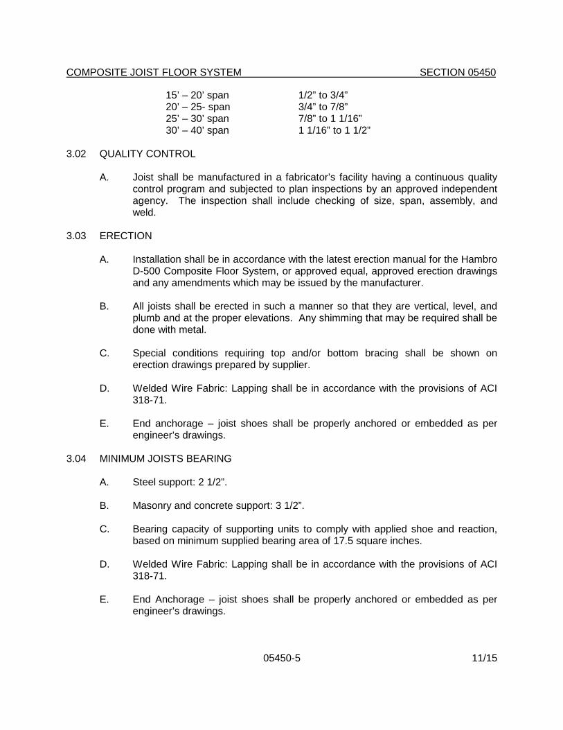
15’ – 20’ span 1/2” to 3/4” 20’ – 25- span 3/4” to 7/8” 25’ – 30’ span 7/8” to 1 1/16” 30’ – 40’ span 1 1/16” to 1 1/2”
3.02 QUALITY CONTROL
A. Joist shall be manufactured in a fabricator’s facility having a continuous quality control program and subjected to plan inspections by an approved independent agency. The inspection shall include checking of size, span, assembly, and weld.
3.03 ERECTION
A. Installation shall be in accordance with the latest erection manual for the Hambro D-500 Composite Floor System, or approved equal, approved erection drawings and any amendments which may be issued by the manufacturer.
B. All joists shall be erected in such a manner so that they are vertical, level, and
plumb and at the proper elevations. Any shimming that may be required shall be done with metal.
C. Special conditions requiring top and/or bottom bracing shall be shown on
erection drawings prepared by supplier.
D. Welded Wire Fabric: Lapping shall be in accordance with the provisions of ACI 318-71.
E. End anchorage – joist shoes shall be properly anchored or embedded as per
engineer’s drawings. 3.04 MINIMUM JOISTS BEARING
A. Steel support: 2 1/2”. B. Masonry and concrete support: 3 1/2”.
C. Bearing capacity of supporting units to comply with applied shoe and reaction,
based on minimum supplied bearing area of 17.5 square inches.
D. Welded Wire Fabric: Lapping shall be in accordance with the provisions of ACI 318-71.
E. End Anchorage – joist shoes shall be properly anchored or embedded as per
engineer’s drawings.

COMPOSITE JOIST FLOOR SYSTEM SECTION 05450
05450-6 11/15
3.05 CONCRETING PRACTICE A. Do not pour concrete in excess of the slab thickness stated on the erection
drawings. B. Do not drop large bucket loads in concentrated areas over joists. Lightly vibrate
concrete.
C. Construction joists made parallel to the joists should be made midway between the joists but never closer than 6” to the top chord.
D. Construction joints made the perpendicular to the joists should be located over
the supporting wall or beam.
E. Stripping – under normal conditions, formwork may be stripped as such time as the concrete has reached a cylinder strength of 500 psi.
3.06 CONSTRUCTION LOADS
A. Bundles of plywood or roll bars shall not be placed on joist system but rather on supporting walls or beams.
B. During construction, the minimum non-composite capacity for a 2 1/2” slab and
joists at 4’-1 1/4” on center, shall be 230 pounds per linear foot.
C. Joists spaced at greater than 4’-1 1/4” on center shall have their non-composite capacity adequately increased to carry the additional load.
D. Construction loads may be applied when the concrete has reached a cylinder
strength of 500 psi.
END OF SECTION

11/15
INSTRUCTIONS FOR EDITING
SECTION 05500
METAL FABRICATIONS
1. Part 2 - Products (General): Edit this portion of the Specification to fit project requirements; add or delete fabrications shown herein.

05500-1 11/15
SECTION 05500
METAL FABRICATIONS
PART 1 - GENERAL 1.01 RELATED DOCUMENTS
A. Drawings and General Provisions of Contract, including General Conditions and other Division 1 Specification Sections, apply to the Work of this Section.
1.02 REFERENCE DOCUMENTS
A. ASTM A36 - Structural Steel.
B. ASTM A53 - Pipe, Steel, Black and Hot-Dipped Zinc-Coated Welded and Seamless.
C. ASTM A283 - Low and Intermediate Tensile Strength Carbon Steel Plates,
Shapes and Bars.
D. ASTM A501 - Hot Formed Welded and Seamless Carbon Steel Structural Tubing.
E. ASTM A512 - Cold-Drawn Buttweld Carbon Steel Mechanical Tubing.
F. AWS - American Welding Society Structural Welding Code.
G. "Metal Finishes Manual" Published by National Association of Architectural Metal
Manufacturer's (NAAMM). 1.03 RELATED WORK
A. Section 04200 - Unit Masonry; installation of loose lintels and attachment of fabrications to masonry.
B. Section 09900 - Painting; finish painting in the field.
1.04 DESCRIPTION OF WORK
A. Miscellaneous metal work shall include items fabricated from iron and steel plates, bars, strips, tubes, pipes and castings that are not a part of structural steel or other metal systems.
B. Miscellaneous metal work shall include loose lintels or other supports that are
not part of building structural system.

METAL FABRICATIONS SECTION 05500
05500-2 11/15
1.05 SUBMITTALS
A. Submit Shop Drawings for fabrication and erection of miscellaneous metal assemblies. Includes plans and elevations at not less than 1/4 inch to 1 ft.-0 in. scale, and include details of sections and connections at not less than 3 in. to 1 ft.-0 in. scale. Indicate all anchorage and accessory items.
PART 2 - PRODUCTS 2.01 METALS
A. Steel:
1. Structural shapes, bars, plates: ASTM A36.
2. Steel plates to be bent or cold-formed: ASTM A283, grade C.
3. Structural tubing: ASTM A501.
4. Cold-drawn tubing: ASTM A512.
5. Pipe: ASTM A53, Type E, Grade E, galvanized where exposed to weather.
6. Flat Rolled Steel Sheets: ASTM A611, class I (cold rolled), or ASTM
A570 (hot rolled). Galvanized steel sheets: ASTM A525 and ASTM A526; G90 coating.
7. Steel Bars: hot rolled, ASTM A575; other bars or bar shapes, ASTM
A663 or ASTM A36.
B. Expansion shields: Type and size to support load imposed.
C. Aluminum Tube Railing: Extruded type. (Brushed Satin finish / Anodized)
D. Stainless Steel:
1. Bar Shapes and Forgings: ASTM A276, type best suited for purpose.
2. Plates, Sheets and Strips: STM A167 or A176, type best suited for purpose.
E. Fasteners
1. General: Furnish all bolts, nuts, screws, clips, washers, and any other fastenings necessary for proper erection of items specified herein.

METAL FABRICATIONS SECTION 05500
05500-3 11/15
a. For ferrous metal use stainless steel on exterior. On interior match adjacent material, or if not applicable, provide zinc coated fasteners.
b. For stainless steel, AISI 300 Series Stainless Steel. Unless noted
otherwise, exposed screws shall be Phillips flat head, countersunk.
2. Products:
a. Toggle Bolts: FS FF-W-84.
b. Bolts & Nuts: ASTM A 307, grade A, hex head.
c. Lag Bolts: FS FF-B-561, square head.
d. Machine Screws: Cadmium-plated steel, FS FF-S-92.
e. Wood Screws: Carbon Steel, FS FF-S-111, flat head.
f. Washers: Carbon Steel, FS FF-W-92, round.
g. Expansion Shields: FS FF-S-325.
h. Lock Washers: Carbon Steel, FS FF-W-84, helical spring type.
i. Powder Driven Fasteners: FS FF-P-395; comply with ANSI
A10.3.
F. Welding Electrodes: As permitted by AWS Code D1.1. 2.02 ACCESS DOORS
A. Access doors shall be furnished and installed in accordance with requirements of Mechanical and Electrical Sections and the Drawings. Doors shall be the product of Inryco/Milcor, Karp or pre-bid approved equal. Install in accordance with the manufacturer's printed instructions as modified herein.
B. Where walls or ceilings consist of fire-resistive assemblies, doors shall be UL
rated the same as the wall or ceiling in which they are installed. Doors shall be as inconspicuous as possible and shall receive the same finish as the material in which they are installed. Utilize doors specifically designed for installation in the type of wall or ceiling material involved.

METAL FABRICATIONS SECTION 05500
05500-4 11/15
2.03 LADDERS
A. Provide galvanized steel ladders at all locations indicated on the drawings. Use welded construction with all welds ground smooth and no visible grind markings. Unless detailed otherwise, construction shall be as follows:
1. Stringers: 2 1/2" x 3/8" flat bar, spaced. Space 24" apart.
2. Rungs: 3/4" round bars, spaced 12" on center, let into stringers.
3. Anchor Brackets: 4" x 6" x 3/8" angle, 4" long. Minimum of two per
string, maximum spacing 4'-0".
B. Furnish galvanized bolts with expansion shields to install ladders against concrete and masonry walls.
C. Provide handholds mounted on walls in conjunction with ladders where shown in
the drawings. Handholds shall be fabricated of 1-inch nominal diameter steel pipe, fitted with flanges, and mounted securely on the wall.
2.04 STEEL RAILINGS
A. Performance Requirements
1. Structural Performance: Design, engineer, fabricate, and install the following metal fabrications to withstand the following structural loads without exceeding the allowable design working stress of the materials involved, including anchors and connections. Apply each load to produce the maximum stress in each respective component of each metal fabrication.
a. Top Rail of Guardrail Systems: Capable of withstanding the
following minimum loads applied as indicated:
1) Concentrated load of 200 pounds applied at any point in any direction and non-concurrently with uniform load.
2) Uniform load of 100 pounds per linear foot applied non-
concurrently with concentrated load, acting vertically downward.
b. Handrails Not Serving as Top Rails: Capable of withstanding the
following loads applied as indicated:
1) Concentrated load of 200 pounds applied at any point and in any direction, non-concurrently with uniform load.

METAL FABRICATIONS SECTION 05500
05500-5 11/15
2) Uniform load of 50 pounds per linear foot applied in any direction, acting non-concurrently with concentrated load.
c. Infill Area of Guardrail Systems: Capable of withstanding a
horizontal concentrated load of 200 pounds applied to one square foot at any point in the system including panels, intermediate rails balusters, or other elements composing the infill area.
d. Treads of Steel Stairs: Capable of withstanding a uniform load of
100 pounds per square foot or a concentrated load of 300 pounds on an area of 4 square inches located in the center of the tread, whichever produces the greater stress.
e. Platforms of Steel Stairs: Capable of withstanding a uniform load
of 100 pounds per square foot.
B. Railing shall be smooth with welded connections. Welded connections shall be ground smooth with no visible grind markings. Joints shall be flush, with concealed fittings.
C. Railing shall be constructed of steel members of sizes and shapes indicated. D. Rails shall run continuously to each post. E. Posts at concrete shall be set plumb in pipe sleeves with non-shrink grout.
F. Handrail brackets: Malleable iron or steel, standard units, complete with
mounting plates and anchoring accessories. Handrails shall be secured to masonry and concrete surfaces by wall brackets with expansion bolts.
G. Fabricate handrails to provide end returns to wall.
2.05 PIPE SLEEVES
Sleeves through masonry or concrete shall be standard weight, wrought iron or galvanized steel, size to allow 1/4 inch between sleeve and pipe.
2.06 LOOSE LINTELS AND SUPPORTS
A. Provide loose structural steel angles, bearing plates, channels, tees, plates, and other steel items as detailed for masonry opening lintels, roof and floor openings, and other locations shown on drawings. Provide galvanized steel for loose items exposed to weather.
B. Length of lintels shall be as required to provide minimum bearing of 4 inches at
each end. Where minimum bearing cannot be obtained due to proximity of

METAL FABRICATIONS SECTION 05500
05500-6 11/15
structural framing member, anchor lintel with clip angle expansion bolted to concrete framing member or welded to steel framing member.
C. Furnish loose lintels and other-support accessories as part of the work of this
Section. Installation of loose lintels shall be under UNIT MASONRY SECTION 04200.
2.07 PAINT
A. Metal primer paint: Rust inhibitive primer, Fed. Spec. TT-P-86, Type II or TT-P-645 (zinc chromate type).
B. Galvanizing: Provide zinc coating for all items exposed to weather or otherwise
specified for galvanizing,
1. ASTM A153 for iron and steel hardware 2. ASTM A123 for rolled, pressed, and forged steel shapes, plates, and
bars. 3. ASTM A386 for assembled steel items
2.08 BRICK VENTS
A. See Section 10200, Louvers and Vents. 2.09 SAFETY TREADS AND NOSINGS - EXTERIOR CONCRETE STAIRS
A. Provide and install cast aluminum safety treads and nosings with abrasive grit surface on all treads of exterior stairs. Dimensions: treads and nosings shall be 4” wide x 6” less than the width of the concrete stair treads.
B.. Approved Manufacturers:
1. Wooster Products, Inc. , Wooster, OH, Type 101, shall be the basis of
specification (www.wooster-products.com). Comparable products of the following manufacturers shall be acceptable.
2. Safe-T-Metal Co., Inc., Syracuse, NY, Style AX (1-800-886-7238)
3. American Safety Tread, Helena, AL, Style 801,
(www.americansafetytread.com). C. Features:
1. “Alumogrit” abrasive cast aluminum #43 prime and secondary ingot, low copper content; corrosion resistant.

METAL FABRICATIONS SECTION 05500
05500-7 11/15
2. Abrasive #20 virgin grain aluminum oxide abrasive, integrally cast into the walking surface. Minimum depth: 1/32” (.79 mm).
3. Cross-hatching: 1/16” (1.59 mm) deep minimum.
4. Fasteners: ¼” (6.35 mm) plated screws and nuts with steel wing
anchors. Holes for fasteners shall be machine made in the factory.
2.10 VERTICAL CHASES
A. Fabricate vertical mechanical pipe chases of minimum 16 gauge sheet steel, shop primed for finish field painting. Refer to drawings for locations and profiles. All chases shall fit tightly to adjacent construction and surfaces. Provide bent metal framing and vertical reinforcement as required by drawings.
1. Extend chases a minimum of 4 inches above finished ceiling.
B. Fabrication and installation of horizontal pipe chases for mechanical equipment
is covered under Division 15. 2.11 STEEL STAIRS
A. General: Construct stairs to conform to sizes and arrangements indicated on drawings. Join pieces together by welding, unless otherwise indicated. Provide complete stair assemblies, including metal framing, hangers, columns, railings, newels, balusters, struts, clips, brackets, bearing plates, and other components necessary for the support of stairs and platforms, and as required to anchor and contain the stairs on the supporting structure.
1. NAAMM Stair Standard: Comply with "Recommended Voluntary
Minimum Standards for Fixed Metal Stairs" in NAAMM "Metal Stair Manual" for commercial class except where more stringent requirements are indicated.
2. Fabricate treads and platforms of exterior stairs to accommodate slopes
to drain in finished traffic surfaces.
B. Stair Framing: Fabricate stringers of structural steel channels, or plates, or a combination thereof, as indicated. Provide closures for exposed ends of stringers. Construct platforms of structural steel channel headers and miscellaneous framing members as indicated. Bolt or weld headers to strings, newels, and framing members to strings and headers; fabricate and join so that bolts, if used, do not appear on finish surfaces.
C. Metal Pan Risers, Subtreads and Subplatforms: Shape metal pans for risers
and subtreads to conform to configuration shown. Provide thickness of structural

METAL FABRICATIONS SECTION 05500
05500-8 11/15
steel sheet for metal pans indicated, but not less than that required, to support total design loading.
1. Form metal pans of uncoated cold-rolled steel sheet, unless otherwise
indicated.
2. Attach risers and subtreads to stringers by means of brackets made of steel angles or bars. Weld brackets to stringers and attach metal pans to brackets by welding, riveting or bolting.
D. Provide Subplatforms of configuration and construction indicated; if not
indicated, of same metal as risers and subtreads, in thickness required to support design loading. Attach subplatform to platform framing members with welds.
E. Stair Railings and Handrails: Comply with applicable requirements specified elsewhere in this section for steel pipe railings and handrails, and as follows:
1. Make bends of consistent radius, preserving the contour of the pipe, or
use prefabricated fittings.
2. Connect railing posts to stair framing by direct welding or as otherwise indicated.
2.12 FABRICATION
A. Use materials of size and thickness indicated, or if not indicated, of the required size and thickness to produce adequate strength and durability in the finished product for intended use. Work to dimensions indicated on drawings using industry proven details of fabrication and support.
B. Form exposed work with accurate angles and surfaces and straight sharp edges.
Ease exposed edges to radius of approximately 1/32 in. unless otherwise indicated. Form bent-metal corners to smallest radius possible without causing grain separation or impairing work.
C. Weld corners and seams continuously and in accordance with recommendations
of AWS. Grind exposed welds smooth and flush, to match and blend with adjoining surfaces.
D. Form exposed connections with hairline joints flush and smooth, using concealed
fasteners wherever possible. Use exposed fasteners of the type indicated, or if not indicated, use Phillips flathead, countersunk screws or bolts.
E. Provide for anchorage of type required, coordinated with supporting structure
and the progress schedule. Fabricate and space anchoring devices as required to provide adequate support for intended use.

METAL FABRICATIONS SECTION 05500
05500-9 11/15
F. Cut, reinforce, drill, and tap miscellaneous metal work to receive other items. G. Shop Painting:
1. Shop paint miscellaneous metal work, except members or portions of members embedded in concrete or masonry, surfaces and edges to be field-welded, and galvanized surfaces.
2. Remove scale, rust and other deleterious materials before shop paint is
applied. Clean surfaces in accordance with Steel Structures Painting Council, SP-3.
3. Apply one shop coat of metal primer paint to fabricated metal items.
H. Fabricate miscellaneous units to the sizes, shapes and profiles indicated or, if
not indicated, of the required dimensions to receive adjacent grating, plates, doors or other work to be retained by framing. Except as otherwise shown, fabricate from structural steel shapes and plates and steel bars of welded construction using mitered corners, welded brackets and splice plates and minimum number of joints for field connections. Equip units with integrally welded anchor strips for casting into poured concrete. Furnish inserts if units must be installed after concrete is poured; except as otherwise indicated, space anchors 2 feet 0 inch o. c.
I. Custom fabricate pipe railings to dimensions and details indicated, with smooth
bends and welded joints ground smooth and flush.
J. Fabricate ladders for locations indicated, with dimensions, spacing details and anchorage as required. Comply with the requirements of ANSI A14.3. For rungs other than round bars, such as ships ladders with flat plate or tubular rungs, provide non-slip surface on the top of each rung, either by coating the rung with aluminum oxide granules set in epoxy resin adhesive, or by using a manufactured rung filled with aluminum oxide grout; or provide heavily serrated profiles.
K. For fabrication of work exposed to view, use only materials which are smooth
and free of surface blemishes such as pittings, seam marks, roller marks, trade names and roughness. Remove blemishes by grinding, or by welding and grinding, prior to cleaning, treating and application of surface finishes including zinc coatings.
L. Preassemble items in shop to greatest extent possible to minimize field splicing
and assembly of units at project site.

METAL FABRICATIONS SECTION 05500
05500-10 11/15
PART 3 - EXECUTION 3.01 FIELD CONDITIONS
A. Verify measurements in field for work fabricated to fit job conditions.
B. Before starting work, examine adjoining work on which miscellaneous metal work is supported, or to which it is fitted or joined.
C. Provide anchorage devices and fasteners where necessary for securing
miscellaneous metal items to in-place construction including threaded fasteners for concrete and masonry inserts, toggle bolts, through-bolts, lag bolts, wood screws and other connections as required.
D. Perform cutting, drilling and fitting required for installation of miscellaneous metal items. Set work accurately in location, alignment and elevation, plumb, level, true and free of rack, measured from established lines and levels.
E. Fit exposed connections accurately together to form tight hairline joints. Weld
connections that are not to be left as exposed joints, but cannot be shop welded because of shipping size limitations. Grind joints smooth and touch-up shop paint coat. Do not weld, cut or abrade the surfaces for exterior units that have been hot-dip galvanized after fabrication, and are intended for bolted or screwed field connections.
3.02 FIELD WELDING
A. Comply with AWS Code for procedures for manual shielded metal-arc welding, the appearance and quality of welds made and the methods used in correcting welding work.
3.03 TOUCH-UP PAINTING
A. Immediately after erection, clean field welds, bolted connections and abraded areas of the shop paint, and paint exposed areas with same materials used for shop painting.
END OF SECTION

11/15
INSTRUCTIONS FOR EDITING
SECTION 05810
EXPANSION CONTROL (WALLS & SURFACES)
1. Part 2 Products: Edit 2.02 Expansion joints to add or delete joint types as appropriate to project scope. Modify joint type specified if inappropriate to specific condition required by project.

05810-1 11/15
SECTION 05810
EXPANSION CONTROL (WALLS AND SURFACES)
PART 1 - GENERAL 1.01 RELATED DOCUMENTS
A. Drawings and General Provisions of Contract, including General Conditions and Division 1 Specifications Sections, shall apply to this Section.
1.02 RELATED WORK
A. Unit Masonry: Section 04200
B. Built up Roofing and Insulation: Section 07510
C. Flashing & Sheet Metal: Section 07600
D. Sealants: Section 07900
E. Acoustical Tile Ceilings: Section 09510 1.03 SUBMITTALS
A. Submit manufacturer's descriptive literature for each type of pre-manufactured expansion joint specified.
B. Drawings: Provide sections through expansion joints, indicating compatibility of pre-
manufactured expansion joints with each type of joint condition required. PART 2 - PRODUCTS 2.01 ACCEPTABLE MANUFACTURERS
A. MM Systems Corp. (basis of specification)
B. Architectural Art Manufacturing, Inc.
C. C/S Group
D. Other manufacturers, when pre-bid approved in accordance with Section 01630, shall be acceptable.
2.02 EXPANSION JOINTS (2" joints)
A. EJ-1 (floor to floor): Heavy duty model, LASF-NB 2-1.

EXPANSION CONTROLS (WALLS & SURFACES) SECTION 05810
05810-2 11/15
B. EJ-2 (floor to floor; new to existing): HFXEM 2-1.
C. EJ-3 (floor to wall): HFXREH 2-1.
D. EJ-4 (wall to wall): FXK 2-1.
E. EJ-5 (wall to corner): FX-L 2-1.
F. EJ-6 (ceiling to ceiling): CX-200
G. EJ-7 (ceiling to wall): CX-200 PART 3 - EXECUTION 3.01 INSPECTION AND PREPARATION
A. Verify that substrates indicated to receive pre-manufactured expansion joints have been properly prepared. Notify architect and Owner’s Representative if any conditions are encountered that will interfere with proper installation of expansion joint covers. Do not proceed with installation until unsatisfactory conditions have been corrected.
3.02 INSTALLATION
A. Install expansion joints in accordance with manufacturer’s written instructions and the approved shop drawings.
B. Securely embed or attach expansion joints to adjacent supporting construction.
Set expansion joints to properly align with adjacent finishes. 3.03 CLEANING
A. Remove all excess materials, packaging, tools and other debris associated with the Work of this Section, and dispose of legally.
END OF SECTION

05820-1 11/15
SECTION 05820
SLIDE BEARINGS
PART 1 - GENERAL 1.01 RELATED DOCUMENTS
A. Drawings and General Provisions of Contract, including General Conditions and other Division 1 Specification Sections, apply to the Work of this Section.
1.02 RELATED WORK
A. Section 05120 - Structural Steel.
B. Section 05211 - Steel Joists.
1.03 REFERENCED CODES
A. Virginia USBC (IBC), Chapters 16 and 17: current edition. B. Fairfax County Special Inspections Program publication: Current Edition.
1.04 SUMMARY OF WORK
A. Provide self-lubricating, slide and fixed low-friction slide bearing assemblies as shown on the Drawings and specified herein. Assemblies shall include all directly connected or welded anchorage hardware.
B. Bearing assemblies shall consist of plane fixed and sliding units of the sizes and
in the locations shown on the drawings. The bearing areas shown on the Drawings shall be net areas exclusive of any bolt holes, and shall be the smaller of the two required plates. Upper plate shall be at least 2" larger in each direction than bottom plate for each type of bearing condition. Both the upper and lower bearing elements shall be made of reinforced “Teflon”, factory bonded to a suitable steel backing plate of 10 gauge minimum thickness.
1.05 SHOP DRAWINGS
A. Submit shop drawings showing material specifications, compliance with applicable standards, sizes, installation details, load data, and manufacturer’s product data for review or approval by the Structural Engineer of Record prior to furnishing slide bearing assemblies.

SLIDE BEARINGS SECTION 05820
05820-2 11/15
PART 2 - PRODUCTS 2.01 APPROVED MANUFACTURERS
A. Basis of Specification: "Fluorogold" Slide Bearings as engineered and manufactured by Seismic Energy Products, L.P. (SEP), Athens, TX (www.sepbearings.com).
B. Other manufacturers, meeting the requirements of this Section and the structural
details shown on the Drawings, shall be acceptable. 2.02 PRODUCTS
A. Backing plates: Structural steel plates meeting ASTM A-36. B. Reinforced “Teflon” Sliding Surfaces: 100 percent virgin tetrafluorenthylene
polymer formulated with inert reinforcing aggregates, cast into sheets and factory bonded to specially prepared metal substrates with special heating cured, high temperature epoxy, capable of operating between - 320 degrees F. and +400 degrees F. The surfaces with similar materials operating against each other shall have a static friction coefficient of not more than 0.06, and shall not deform more than 0.002 inches when subjected to allowable static load.
1. Physical Properties:
a. Tensile Strength: 2000 psi per ASTM D 1457. b. Tensile Elongation: 200% per ASTM D 1457. c. Hardness, Durometer (Shore A): 60-70 per ASTM D2240. d. Specific Gravity: 2.10 per ASTM D792. e. Melting Point: 327 degrees F (+/-10 degrees) per ASTM D1457
2. Standard surface thickness: 3/32” unless noted otherwise on the Drawings.
PART 3 - EXECUTION 3.01 INSPECTION
A. Inspect the areas where the slide bearings shall be installed. Notify the Architect and Owner’s Representative of any deviations from the Drawings and final approved shop drawings, or other deficiencies that would prevent proper installation and performance of the slide bearings. Do not proceed with the work until such conditions have been corrected.

SLIDE BEARINGS SECTION 05820
05820-3 11/15
3.02 INSTALLATION A. Clean operating surfaces of bearing assemblies thoroughly before final assembly.
B. Install bearings in conformance with the structural details shown on the Drawings
and the approved, final shop drawings. Install in the exact locations indicated, at the required elevations, true to orientation and level.
C. Protect during and after installation from contamination of bearing surfaces and
damage due to placing of other materials.
3.03 CLEAN UP
A. Remove all excess materials associated with the Work of this Section from the premises, and dispose of legally offsite.
END OF SECTION