
Sect4
28
AMERICAN Ductile Iron Fastite ® , Flex-Ring ® , and Lok-Ring ® Fittings AMERICAN DUCTILE IRON PIPE
-
Upload
ashraf-adel-nashed-zaki -
Category
Documents
-
view
212 -
download
0
description
alico 4
Transcript of Sect4

AMERICANDuctile IronFastite®, Flex-Ring®,and Lok-Ring®
Fittings
AMERICAN DUCTILE IRON PIPE

INTERNATIONAL SALESP.O. Box 2727Birmingham, AL 35202-2727Telephone: 205/325-7815Facsimile: 205/325-8014
Castle Rock
Jenks
Louisville
Howell
ATLANTA3575 Koger BoulevardSte. 240, Duluth, GA 30096Telephone: 770/381-3611Facsimile: 770/381-3688
North Carolina Satellite Office:3140 Goldmist DriveBuford, GA 30519Telephone: 770/846-1493Facsimile: 770/381-3688
South Carolina Satellite Office:PMB #307320-L Broad River RoadIrmo, SC 29063Telephone: 803/407-9107Facsimile: 803/407-9108
BIRMINGHAMIII Riverchase Office PlazaSte. 226Birmingham, AL 35244Telephone: 205/307-2800Facsimile: 205/307-2806
Kentucky Satellite Office:3703 Woodgrove PlaceLouisville, KY 40245Telephone: 502/243-0510Facsimile: 502/243-0650
Tennessee Satellite Office:7003 Chadwick Dr., Ste. 361Brentwood, TN 37027Telephone: 615/370-2900Facsimile: 615/370-2901
CHICAGO2225 Enterprise Road, Ste. 2502 Westchester, IL 60154Telephone: 708/947-7680Facsimile: 708/947-7685
Michigan Satellite Office:903 S. Latson RoadSte. 291Howell, MI 48843Telephone: 517/545-4604Facsimile: 517/545-4641
Grand Rapids Regional Depot:6170 Alden Nash RoadAlto, MI 49302Telephone: 616/868-7041Facsimile: 616/868-7046
DALLASPreston Plaza17950 Preston Road, Ste. 990Dallas, TX 75252Telephone: 214/237-1900Facsimile: 214/237-1901
Arkansas Satellite Office:6 Ouachita CoveMaumelle, AR 72113Telephone: 501/851-0947Facsimile: 501/851-4111
Oklahoma Satellite Office:514 N. Douglas StreetJenks, OK 74037Telephone: 918/298-4446Facsimile: 918/298-4449
Texas Satellite Office:P.O. Box 1389Austin, TX 78767Telephone: 512/445-5631Facsimile: 205/307-3873
KANSAS CITY6445 Carter AvenueP.O. Box 40Shawnee Mission, KS 66201-0040(Depot located on Carter Ave. at65th St., Merriam, KS)Telephone: 913/432-4112Facsimile: 913/432-4157
Colorado Satellite Office:P.O. Box 1735Castle Rock, CO 80104Telephone: 303/660-2321Facsimile: 303/660-2317
MINNEAPOLIS21695 Highview AvenueLakeville, MN 55044Telephone: 952/469-1100Facsimile: 952/469-3311
Washington Satellite Office:P.M.B. 222-3930 A Street SESte. 305, Auburn, WA 98002Telephone: 253/735-8281Facsimile: 253/735-8278
Minneapolis Regional Depot:21695 Highview AvenueLakeville, MN 55044
Portland Regional Depot:9700 North HurstPortland, OR 97217
ORLANDO300 Primera Blvd., Suite 240Primera FourLake Mary, FL 32746Telephone: 407/804-1420Facsimile: 407/804-1201
Florida Satellite Office:110 Paseos WayJupiter, FL 33458Telephone: 561/747-6640Facsimile: 561/747-6987
Plant City Regional Depot:2910 Sammonds RoadPlant City, FL 33563Telephone: 813/752-6521Facsimile: 813/759-6504
Pompano Regional Depot:4000 N. Dixie HighwayPompano Beach, FL 33064-4355Telephone: 954/781-6568Facsimile: 954/946-4091
PITTSBURGH2581 Washington Rd.Ste. 220/222Pittsburgh, PA 15241Telephone: 412/851-1230Facsimile: 412/851-1243
New England Satellite Office:637 Wyckoff AvenueSte. 230, Wyckoff, NJ 07481Telephone: 201/891-0644Facsimile: 201/891-0971
New Jersey Satellite Office:1614-O Union Valley RoadSte. 304West Milford, NJ 07480Telephone: 973/853-4288Facsimile: 973/853-4289
Virginia Satellite Office:13817 Shadow Ridge Rd.Midlothian, VA 23112Telephone: 804/763-4671Facsimile: 804/763-0154
Richmond Regional Depot:5000 Deepwater Terminal Rd.Richmond, VA 23234
SACRAMENTO4811 Chippendale DriveSte. 707Sacramento, CA 95841-2554Telephone: 916/339-8151Facsimile: 916/339-8161
Phoenix Satellite Office:2303 N. 44th StreetSuite 14-1049Phoenix, AZ 85008-2442Telephone: 602/275-3540Facsimile: 602/275-2276
Phoenix Regional Depot:4703 W. Pasadena Ave.Glendale, AZ 85301
Sacramento Satellite Office:18377 Stanislaus StreetFountain Valley, CA 92708Telephone: 714/593-0325Facsimile: 205/307-3886
District Sales Offices
AmericanDuctile Iron Pipe(A Division of ACIPCO)General Offices and Plants
Mailing Address:P.O. Box 2727Birmingham, AL 35202-2727Street Address:1501 31st Avenue NorthBirmingham, AL 35207
Customer Service:1-800-442-ADIP (2347)Facsimile 1-800-442-2348Internet Address: http://www.acipco.com

4-1
AMERICAN furnishes a complete lineof 4"-64" Fastite, 16"-48" Flex-Ring, and54"-64" Lok-Ring fittings meeting theapplicable requirements of AWWA C110 orC153, depending on diameter and joint.These fittings all employ the standardFastite or Fast-Grip gasket seal and thejoints meet the applicable requirements ofAWWA C111. Many of these fittings arenot specifically listed in the AWWA standards because of joints, outlets, orother variations, and are designated as“AMERICAN Standard.”
Fastite fittings are used extensively inunderground service with Fastite joint pipe.Because they are boltless, less labor inten-sive, ergonomically friendly, and becausejoint restraint can be facilitated in the fieldby using AMERICAN’s Fast-Grip® gasket inthe 4"-30" sizes, they are gaining populari-ty over standard mechanical joint fittings.
When welded joint restraint is desired,Flex-Ring or Lok-Ring fittings can also beused, depending on size. These joints arealso essentially boltless and use the stan-dard Fastite gasket for joint sealing.Additionally, field adaptable joint restraint isavailable for 4"-30" Fastite and 14"-36"Flex-Ring by use of AMERICAN’s Fast-Gripgaskets or Field Flex-Rings, respectively.See Section 9 for more information onRestrained Joints.
Fastite, Flex-Ring, and Lok-Ring fit-tings are normally furnished complete withstandard Fastite plain rubber gaskets and asufficient supply of Fastite joint lubricant.Restraining elements for Flex-Ring or Lok-Ring fittings may be shipped either withthe fittings or joining pipe, dependent onjoint type, fitting configuration, etc. SeeSection 9.
All sizes of Fastite, Flex-Ring, and Lok-Ring fittings are furnished ductile iron only.Fittings for pressure ratings of 250 and 350psi are furnished as shown in the tables inthis Section. Fittings for pressure ratingshigher than shown are available for specialapplications.
4"-16" Fastite fittings are furnishedfusion-bonded-epoxy (FBE) coated andlined only. The FBE coating/lining meetsthe applicable requirements of AWWAC116, and both FBE and cement linings areANSI/NSF Standard 61 certified for contactwith potable water.
All other fittings are normally fur-nished with cement lining in accordancewith AWWA C104 and with an outsideasphaltic coating. They can also be fur-nished asphaltic coated or uncoated inside.For special conditions, other types of coat-ings and linings may be available. SeeSection 11.
AMERICAN DUCTILE IRON PIPE
AMERICAN Ductile Iron Fastite®, Flex-Ring®, and Lok-Ring® Fittings
The principal standards covering fittings are ANSI/AWWA C110/A21.10 and ANSI/AWWAC153/A21.53. The principal standard covering joints is ANSI/AWWA C111/A21.11. These andother standards are referenced throughout this Section by the full ANSI/AWWA designation orby only the AWWA numbering, such as AWWA C110 or C153.

4-2
AMERICAN DUCTILE IRON PIPE
AMERICAN Ductile Iron Fastite®, Flex-Ring®, and Lok-Ring® Fittings
1. Fittings in the following tables with theheading “ANSI/AWWA C153/A21.53” areessentially as specified in that Standard. Fittingsin tables with the heading “AMERICANStandard” are either not included in theANSI/AWWA Standard or vary therefrom inweights, dimensions, and/or joints.
2. Fittings are manufactured of ductileiron qualified as per grade 70-50-05 (minimumtensile strength: 70,000 psi; minimum yieldstrength: 50,000 psi; minimum elongation:5%) as specified in AWWA C110 and C153.
3. Weights of accessories are not includedin weights of fittings shown in tables unlessspecifically noted. For weights of accessories,see Section 2 or Section 9.
4. For allowable joint deflection of Fastite,Flex-Ring, and Lok-Ring fitting joints, see Table4-3.
5. All pressure ratings are for water ser-vice.
6. Some fittings are available with bodymetal thickness and weights other than shownin the tables. Some fittings are available in dif-ferent sizes and with different size combina-tions than shown. All sizes and body metalthicknesses listed may not be available due toequipment changes. Check AMERICANregarding special requirements.
7. See Section 7 for AMERICAN Specials.
8. Fittings may be furnished by AMERI-CAN which are manufactured by others. Anysuch fittings will normally be manufactured inaccordance with appropriate ANSI/AWWAStandards.
9. The 250 psi rating for 54"-64" fittingsis an AMERICAN Standard, based on perfor-
mance testing. 54"-64" fittings are ratedonly 150 psi in AWWA C153, although thatstandard provides for higher pressure rat-ings by the manufacturer (AMERICAN).
10. Center-to-socket dimensions, wallthicknesses, and weights may vary from thoseshown in the following tables depending onfoundry practice.
11. The locations of taps, bosses, bases,or other special options when available on fit-tings shall be specified by the Purchaser asshown on page 6-5 for similar body type fit-tings. Likewise, end types and end sizes used indescriptions must be specified in numberingsequence shown on pages 6-5 and 6-6 andthe illustrations in this section.
12. Lateral or wye branch fittings withFastite, Flex-Ring, and Lok-Ring end connec-tions are not shown in this section. For small-diameter varied angle lateral and tangentialconnections to larger mains, shop-welded out-let pipes are normally preferable and can befurnished with all joining connections as notedin Section 7. For larger or full-opening require-ments, some 45º lateral and true wye configu-rations can also be furnished with these push-on end connections. (Contact AMERICAN foravailability.) These wye fittings are special, andfor economy and availability, alternative com-binations of other standard fittings may bepreferable in some cases. (See alternatives asdepicted in Sections 5 and 6, etc.)
13. AMERICAN Flex-Ring fittings willwork as push-on unrestrained fittings aswell [as “Fastite” without restraint ringsand/or spigot weldments], as long as suit-able external restraint [thrust blocks, etc.] isapplied. Flex-Ring fittings are thus furnishedas “Fastite” fittings in many sizes and con-figurations, at Foundry option.
General Notes Relating to Fastite, Flex-Ring, and Lok-Ring Fittings

4-3
AMERICAN DUCTILE IRON PIPE
AMERICAN Ductile Iron Fastite®, Flex-Ring®, and Lok-Ring® Fittings
ANSI/AWWA C153/A21.53 and AMERICAN Standard
Fastite, Flex-Ring, and Lok-Ring Fittings Joint Dimensions
*Dimensions subject to change at our option.For Fastite pipe dimensions, see Section 2.For Flex-Ring and Lok-Ring pipe dimensions, see Section 9.**Fittings furnished interchangeably as Fastite or Flex-Ring may have the same dimensions/appearance (e.g. Flex-Ring per the bottom cut) in many sizes and configurations.
DAE
Fastite**
16"-48" Flex-Ring**
Lok-Ring
AFB
Table No. 4-1
14 4.80 - - 3.75 - 7.44 -16 6.90 - - 3.75 - 9.54 -18 9.05 - - 4.00 - 11.78 -10 11.10 - - 4.50 - 14.05 -12 13.20 - - 4.50 - 16.34 -14 15.30 - - 4.50 - 19.37 -16 17.40 7.38 - 4.50 20.72 21.49 -18 19.50 8.20 - 4.50 22.92 23.71 -20 21.60 8.20 - 4.50 25.50 25.83 -24 25.80 8.96 - 8.96 30.70 30.70 -30 32.00 9.63 - 9.63 37.04 37.04 -36 38.30 9.63 - 9.63 43.54 43.54 -42 44.50 10.84 - 7.50 48.64 50.62 -48 50.80 12.37 - 8.00 55.14 56.98 -54 57.56 - 10.07 8.50 62.14 - 62.1460 61.61 - 10.57 8.75 66.27 - 66.2764 65.67 - 10.57 9.00 70.45 - 70.45
Sizein.
AOutside
Diameter
BSocketDepth
Flex-Ring
CSocketDepth
Lok-Ring
D**SocketDepthFastite
E*Bell
O.D.**Fastite
F*BellO.D.
Flex-Ring
G*BellO.D.
Lok-Ring
Dimensions in Inches
3 1/2"
G
A
C

4-4
AMERICAN DUCTILE IRON PIPE
Notes:*4"-14" Fastite Plain Ends and Flex-Ring Ends are not available on most fittings.**The laying length of fitting plain ends is not necessarily the same as the gauge length. In general, depending on the
fitting configuration (C110 or C153, etc.) and also the size and joint, the laying length of a fitting plain end will beapproximately 8”-10” longer than the laying length of the same fitting (with a) bell end. Contact AMERICAN whenmore precise dimensions are required.
B
A A
A
C
D
Lok-Ring End
16"-48"Flex-Ring End
Fastite Plain End
Table No. 4-2
Sizein.*
AOutside
Diameterin.
B**Fastite
MinimumGauge Length
in.
DFlex-RingMinimum
Gauge Lengthin.
CLok-RingMinimum
Gauge Lengthin.
AMERICAN Ductile Iron Fastite®, Flex-Ring®, and Lok-Ring® Fittings
ANSI/AWWA C153/A21.53 and AMERICAN Standard
Fastite Plain End, Flex-Ring End, and Lok-Ring End
Standard Dimensions
4 4.8 - - -6 6.9 - - -8 9.05 - - -
10 11.1 - - - 12 13.2 - - -14 15.3 8 - - 16 17.4 8 9 -18 19.5 8 9 -20 21.6 8 9 - 24 25.8 8 10 -30 32.0 8 10 -36 38.3 8 10 -42 44.5 8 11 1/2 -48 50.8 8 13 -54 57.56 10 - 1260 61.61 10 - 1364 65.67 10 - 13
Fastite Plain End* Lok-Ring End
16”-48”Flex-Ring End

4-5
AMERICAN DUCTILE IRON PIPE
Table No. 4-3
Sizein. Deflection
Angle (Deg.)
“S”Separation In. Deflection
Angle (Deg.)Deflection
Angle (Deg.)
4 5.00 0.375 5.00 -6 5.00 0.562 5.00 -8 5.00 0.750 5.00 -
10 5.00 0.937 5.00 -12 5.00 1.125 5.00 -14 4.00 1.030 4.00 - 16 3.75 1.010 3.75 -18 3.75 1.190 3.75 -20 3.50 1.250 3.50 - 24 3.00 1.375 3.00 -30 2.50 1.375 2.50 - 36 2.00 1.375 2.00 -42 3.00 2.250 2.00 -48 1.50 1.250 1.50 -54 3.00 2.875 - .560 3.00 3.125 - .564 3.00 3.375 - .5
Fastite Flex-Ring Lok-Ring
Allowable Deflection Push-On Fitting Joints
Maximum Allowable SeparationPush-On Fitting Joints
Maximum allowable separation, "S", in a push-on fitting joint is approximately equal to the medianpipe diameter in inches times the sine of the deflection angle. This is provided for information onlyand should not be used to determine precise joint deflection.
S
D-t
t

4-6
AMERICAN DUCTILE IRON PIPE
*AWWA C153 configurations with shorter center-to-socket dimensions, etc. may be furnished in some cases in the18”-20” size range. Check AMERICAN. if dimensions are critical.
**18" and larger Fastite, and 16" and larger Flex-Ring and Lok-Ring 90° Bends may be furnished with Fastite PlainEnds, Flex-Ring Ends, or Lok-Ring Ends. See Table No. 4-2.
† Higher pressure ratings are available on special applications. Pressure ratings may be limited below the valuesshown by the pressure rating of the pipe to which fitting is attached, or the restrained joint used. Based on performance testing per AWWA C153, AMERICAN can rate 30”-48” C153 bends 350 psi. Check AMERICAN.See General Notes on page 4-2.
†† 16" Flex-Ring fittings may have greater “T” dimensions than those shown.^ Fastite fittings with these weights have different dimensions than are shown in this table. Contact AMERICAN when
dimensions are critical.^^ 18”-48” Fastite and Flex-Ring bends can have the same appearance [both have basic cross-section of top
middle “cut”].
A
A
T R
A
T R
A
A
A
T R
Fastite Bell-Bell**^^ Flex-Ring Bell-Bell**^^ Lok-Ring Bell-Bell**
Table No. 4-4
14 350 0.34 4.0 3.00 32 - -16 350 0.36 5.0 4.00 48 - -18 350 0.38 6.5 5.38 72 - -10 350 0.40 7.5 6.25 109 - -12 350 0.42 9.0 7.50 142 - -14 350 0.47†† 14.0 11.50 231 - -16 350 0.50†† 15.0 12.50 277 515 -18 350 0.75 16.5 14.00 720 720 -20 350 0.80 18.0 15.50 815 815 -24 350 0.61 17.0 15.50 760 760 -30 250 0.66 22.75 20.50 1290 1290 -36 250 0.74 25.75 23.50 1810 1810 -42 250 0.82 29.25 26.50 2784 2784 -48 250 0.90 33.25 30.50 3960 3960 -54 250 0.90 37.0 34.25 3750 - 393060 250 0.94 39.5 36.50 4390 - 462064 250 0.99 42.0 38.75 5170 - 5385
Sizein.
Pressure†Rating
psi T A R Fastite Flex-Ring Lok-Ring
Dimensions in Inches Weight in Pounds
AMERICAN Ductile Iron Fastite®, Flex-Ring®, and Lok-Ring® Fittings
ANSI/AWWA C153/A21.53* and AMERICAN Standard
90° Bends (1/4th)

4-7
*AWWA C153 configurations with lesser weights and dimensions may be furnished in some sizes at Foundry option.Check AMERICAN.**Fastite, Flex-Ring, and Lok-Ring Bends may be furnished with Fastite Plain Ends, Flex-Ring Ends, or Lok-Ring Ends.
See Table No. 4-2.***Smaller sizes are available on special applications. Check AMERICAN.† Higher pressure ratings are available on special applications. Check AMERICAN.See General Notes on page 4-2.
A AT
RR
AT
AA
T
R
A
Fastite Bell-Bell** Flex-Ring Bell-Bell** Lok-Ring Bell-Bell**
Table No. 4-5
30 250 1.03 15.0 19.9 1415 1585 -36 250 1.15 28.0 42.4 2780 2895 -42 250 1.28 31.0 42.5 3315 4010 -48 250 1.42 24.0 35.5 3505 4430 -54 250 0.90 24.0 36.8 3115 - 329560 250 0.94 24.0 36.4 3495 - 372064 250 0.99 30.0 46.3 4520 - 4740
Size***in.
Pressure†Rating
psi T A R Fastite Flex-Ring Lok-Ring
Dimensions in Inches Weight in Pounds
AMERICAN DUCTILE IRON PIPE
AMERICAN Ductile Iron Fastite®, Flex-Ring®, and Lok-Ring® Fittings
ANSI/AWWA C153/A21.53* and AMERICAN Standard
60° Bends (1/6th)

4-8
AMERICAN DUCTILE IRON PIPE
*AWWA C153 configurations with shorter center-to-socket dimensions, etc. may be furnished in some cases in the18”-20” size range. Check AMERICAN if dimensions are critical.
**18" and larger Fastite and 16" and larger Flex-Ring and Lok-Ring 45° Bends may be furnished with Fastite PlainEnds, Flex-Ring Ends, or Lok-Ring Ends. See Table No. 4-2.
† Higher pressure ratings are available on special applications. Based on performance testing per AWWA C153, AMERICAN can rate 30”-48” C153 bends 350 psi. Check AMERICAN.
†† 16" Flex-Ring fittings may have greater “T” dimensions than those shown.See General Notes on page 4-2.
^Fastite fittings with these weights have different dimensions than are shown in this table. Contact AMERICAN whendimensions are critical.
^^18”-48” Fastite and Flex-Ring bends can have the same appearance [both have basic cross-section of top middle “cut”].
A AT
R
A AT
RR
AT
A
Fastite Bell-Bell**^̂^̂ Flex-Ring Bell-Bell**^̂^̂ Lok-Ring Bell-Bell**
Table No. 4-6
14 350 0.34 2.0 2.41 1127 11- -16 350 0.36 3.0 4.83 1140 11- -18 350 0.38 3.5 5.75 1159 11- -10 350 0.40 4.5 7.85 1 88 1- -12 350 0.42 5.5 9.66 1117 1- -14 350 0.47†† 7.5 12.06 1177 1- -16 350 0.50†† 8.0 13.25 1210 1425 -18 350 0.75 8.5 14.50 1595 1595 -20 350 0.80 9.5 16.88 1665 1665 -24 350 0.61 7.5 14.50 1620 1620 -30 250 0.66 10.5 19.92 1010 1010 -36 250 0.74 12.0 23.54 1395 1395 -42 250 0.82 14.0 27.20 2235 2235 -48 250 0.90 15.0 29.60 2960 2960 -54 250 0.90 20.28 42.32 2890 - 307060 250 0.94 21.26 44.08 3335 - 356064 250 0.99 22.24 45.85 3865 - 4085
Sizein.
Pressure†Rating
psi T A R Fastite Flex-Ring Lok-Ring
Dimensions in Inches Weight in Pounds
AMERICAN Ductile Iron Fastite®, Flex-Ring®, and Lok-Ring® Fittings
ANSI/AWWA C153/A21.53* and AMERICAN Standard
45° Bends (1/8th)
4-9
AMERICAN DUCTILE IRON PIPE
Fastite Bell-Bell** Flex-Ring Bell-Bell** Lok-Ring Bell-Bell**
*AWWA C153 configurations with lesser weights and dimensions may be furnished in some sizes at Foundry option.Check AMERICAN.**Fastite, Flex-Ring, and Lok-Ring Bends may be furnished with Fastite Plain Ends, Flex-Ring Ends, or Lok-Ring Ends.
See Table No. 4-2.***Smaller sizes are available on special applications. Check AMERICAN.† Higher pressure ratings are available on special applications. Check AMERICAN.
See General Notes on page 4-2.^ Fastite fittings with these weights have different dimensions than are shown in this table. Contact AMERICAN when
dimensions are critical.
A
T
R
A
T
R
A A A
T
R
A
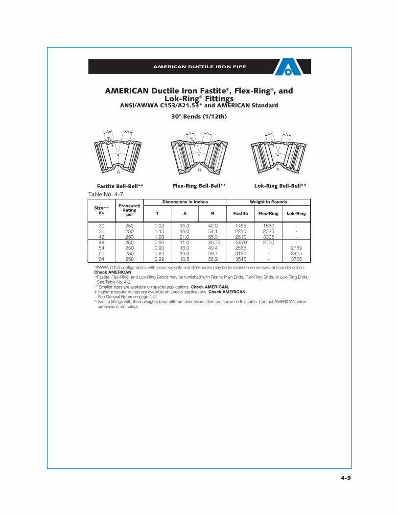
Table No. 4-7
30 250 1.03 15.0 42.9 1455 1630 -36 250 1.15 18.0 54.1 2210 2335 -42 250 1.28 21.0 65.3 2610 3305 -48 250 0.90 11.0 30.79 3670^ 2700 -54 250 0.90 16.0 49.4 2585 - 276560 250 0.94 19.0 59.7 3180 - 340564 250 0.99 18.5 56.9 3545 - 3760
Size***in.
Pressure†Rating
psi T A R Fastite Flex-Ring Lok-Ring
Dimensions in Inches Weight in Pounds
AMERICAN Ductile Iron Fastite®, Flex-Ring®, and Lok-Ring® Fittings
ANSI/AWWA C153/A21.53* and AMERICAN Standard
30° Bends (1/12th)

4-10
AMERICAN DUCTILE IRON PIPE
Fastite Bell-Bell**^̂^̂ Flex-Ring Bell-Bell**^̂^̂ Lok-Ring Bell-Bell**
Table No. 4-8
*AWWA C153 configurations with shorter center-to-socket dimensions, etc. may be furnished in some cases in the18”-20” size range. Check AMERICAN if dimensions are critical.
**18" and larger Fastite and 16" and larger Flex-Ring and Lok-Ring 221⁄2° Bends may be furnished with Fastite PlainEnds, Flex-Ring Ends, or Lok-Ring Ends. See Table No. 4-2.
† Higher pressure ratings are available on special applications. Based on performance testing per AWWA C153, AMERICAN can rate 30”-48” C153 bends 350 psi. Check AMERICAN.
†† 16" Flex-Ring fittings may have greater “T” dimensions than those shown.See General Notes on page 4-2.
^Fastite fittings with these weights have different dimensions than are shown in this table. Contact AMERICAN whendimensions are critical.
^^18”-48” Fastite and Flex-Ring bends can have the same appearance [both have basic cross-section of top middle “cut”].
A A
T
R
A A
T
R
A
T
R
A
4 350 0.34 1.5 2.51 26 - -16 350 0.36 2.0 5.03 37 - -18 350 0.38 2.5 6.94 54 - -10 350 0.40 3.0 8.80 78 - -12 350 0.42 3.5 10.05 100 - -14 350 0.47†† 7.5 25.12 158 - -16 350 0.50†† 8.0 27.62 185 430 -18 350 0.75 8.5 30.19 600 600 -20 350 0.80 9.5 35.19 670 670 -24 350 0.61 4.5 15.10 525 525 -30 250 0.66 6.75 22.60 900 900 -36 250 0.74 7.75 27.70 1220 1220 -42 250 0.82 9.00 31.40 1972 1972 -48 250 0.90 10.00 36.50 2630 2630 -54 250 0.90 10.24 37.65 2125 - 230560 250 0.94 10.63 38.36 2425 - 265064 250 0.99 11.02 39.06 2785 - 3000
Sizein.
Pressure†Rating
psi T A R Fastite Flex-Ring Lok-Ring
Dimensions in Inches Weight in Pounds
AMERICAN Ductile Iron Fastite®, Flex-Ring®, and Lok-Ring® Fittings
ANSI/AWWA C153/A21.53* and AMERICAN Standard
22 1/2° Bends (1/16th)

4-11
AMERICAN DUCTILE IRON PIPE
*AWWA C153 configurations with shorter center-to-socket dimensions, etc. may be furnished in some cases in the18”-20” size range. Check AMERICAN if dimensions are critical.
**18” and larger Fastite and 16" and larger Flex-Ring and Lok-Ring 111⁄4° Bends may be furnished with Fastite PlainEnds, Flex-Ring Ends, or Lok-Ring Ends. See Table No. 4-2.
† Higher pressure ratings are available on special applications. Based on performance testing per AWWA C153, AMERICAN can rate 30”-48” C153 bends 350 psi. Check AMERICAN.
††16” Flex-Ring fittings may have greater “T” dimensions than those shown.See General Notes on page 4-2.
^ Fastite fittings with these weights have different dimensions than are shown in this table. Contact AMERICAN whendimensions are critical.
^^ 18”-48” Fastite and Flex-Ring bends can have the same appearance [both have basic cross-section of topmiddle “cut”].
A AT
R
AT
R
AAT
R
A A
Fastite Bell-Bell**^̂^̂ Flex-Ring Bell-Bell**^̂^̂ Lok-Ring Bell-Bell**Table No. 4-9
14 350 0.34 1.25 2.54 25 - -16 350 0.36 1.5 5.08 34 - -18 350 0.38 1.75 6.40 50 - -10 350 0.40 2.0 7.61 71 - -12 350 0.42 2.25 7.61 89 - -14 350 0.47†† 7.5 50.75 130 - -16 350 0.50†† 8.0 55.81 165 430 -18 350 0.75 8.5 60.94 605 605 -20 350 0.80 9.5 71.06 675 675 -24 350 0.89 3.0 15.33 490 490 -30 250 0.66 4.75 25.40 830 830 -36 250 0.74 5.00 27.90 1100 1100 -42 250 0.82 6.00 33.00 1934 1934 -48 250 0.90 6.5 33.50 2350 2350 -54 250 0.90 6.5 38.07 1820 - 200060 250 0.94 7.0 40.61 2095 - 232064 250 0.99 7.0 38.07 2375 - 2590
Sizein.
Pressure†Rating
psi T A R Fastite Flex-Ring Lok-Ring
Dimensions in Inches Weight in Pounds
AMERICAN Ductile Iron Fastite®, Flex-Ring®, and Lok-Ring® Fittings
ANSI/AWWA C153/A21.53* and AMERICAN Standard
11 1/4° Bends (1/32nd)

4-12
AMERICAN DUCTILE IRON PIPE
AT
R
A
Lok-Ring Bell-Bell**
AMERICAN Flex-Ring* and Lok-Ring® FittingsAMERICAN Standard
5 5/8° Bends (1/64th)
Table No. 4-10
48 250 0.90 5.00 45.78 227054 250 0.90 6.50 76.33 200060 250 0.94 6.50 71.24 227564 250 0.99 7.00 76.33 2590
Sizein.
PressureRating
psi T A R
Weight lb
Dimensions in Inches
* 48” table data are for Flex-Ring all-bell fitting, where as 54”-64” table data are for Lok Ring all-bell fitting.**5 5/8° Bends may be furnished with Flex-Ring or Lok-Ring Ends, depending on size. See Table No. 4-2.See General Notes on page 4-2.

4-13
*4"-16" and 24"-64" fittings are generally per AWWA C153. AWWA C153 or C110 configurations may be furnished insome sizes in the 16”-48” size range. Check AMERICAN. While AWWA C153 shows 54”-64” fittings with 150 psiratings, AMERICAN rates many 54”-64” fittings 250 psi as AMERICAN Standard based on performance testing.
**18" and larger Fastite and 16" and larger Flex-Ring and Lok-Ring Tees and Crosses may be furnished on the runswith Fastite Plain Ends, Flex-Ring Ends, or Lok-Ring Ends. See Table No. 4-2.
† Higher pressure ratings are available on special applications. Check AMERICAN.Note: Tees and Crosses with smaller reductions may be available; however, welded-on outlets are normally prefer-able in these cases from a layout, installation, and economical standpoint. See Section 7.
†† 16" Flex-Ring fittings may have greater “T” and “T1” dimensions than those shown.See General Notes on page 4-2.
J
H
T
T
T
H
2
3
1
1
HH
J
T
2
3
1
1
J
4
Fastite All Bell** Tee
Fastite All Bell** Cross
J
H
T T
H
2
3
1
1
Flex-Ring All Bell** Tee
JT T
2
3
1
1
HH
Flex-Ring All Bell** Cross
4
J
J
H
T T
H
2
3
1
1
Lok-Ring All Bell** Tee
JT T
2
3
1
1
HH
Lok-Ring All Bell** Cross
4
J
Table No. 4-11
14 14 350 0.34 0.34 4.0 4.0 147 1- - 60 - -16 14 350 0.36 0.34 4.0 5.0 164 - - - - -16 16 350 0.36 0.36 5.0 5.0 170 - - 88 - -18 14 350 0.38 0.34 4.0 6.5 89 - - - - -18 16 350 0.38 0.36 5.0 6.5 94 - - - - -18 18 350 0.38 0.38 6.5 6.5 103 - - 127 - -10 14 350 0.40 0.34 4.0 7.5 131 - - - - -10 16 350 0.40 0.36 5.0 7.5 135 - - - - -10 18 350 0.40 0.38 6.5 7.5 142 - - - - -10 10 350 0.40 0.40 7.5 7.5 158 - - - - -12 14 350 0.42 0.34 4.0 8.75 167 - - - - -12 16 350 0.42 0.36 5.0 8.75 170 - - - - -12 18 350 0.42 0.38 6.5 8.75 176 - - - - -12 10 350 0.42 0.40 7.5 8.75 191 - - - - -12 12 350 0.42 0.42 8.8 8.75 202 - - 244 - -14 14 350 .47†† .34†† 14.0 14.0 - - - - - -14 16 350 .47†† .36†† 14.0 14.0 249 - - - - -14 18 350 .47†† .38†† 14.0 14.0 - - - - - -14 10 350 .47†† .40†† 14.0 14.0 266 - - - - -14 12 350 .47†† .42†† 14.0 14.0 276 - - - - -14 14 350 .47†† .47†† 14.0 14.0 304 - - 368 - -
Sizein. Pressure
Ratingpsi † T H J Fastite
All Bell**
FastiteAll Bell
**
**Flex-Ring
All Bell
**Flex-Ring
All Bell
**Lok-Ring
All Bell
**Lok-Ring
All Bell
Tee Cross
T1
Dimensions in Inches Weight in Pounds
Run Branch
AMERICAN Ductile Iron Fastite®, Flex-Ring®, and Lok-Ring® Fittings
ANSI/AWWA C153/A21.53* and AMERICAN Standard
Tees and Crosses
AMERICAN DUCTILE IRON PIPE

4-14
AMERICAN DUCTILE IRON PIPE
Table No. 4-11 —Continued
16 14 350 .50†† .34†† 15.0 15.0 - 645 - - 675 -16 16 350 .50†† .36†† 15.0 15.0 298 655 - - 705 -16 18 350 .50†† .38†† 15.0 15.0 302 670 - - 730 -16 10 350 .50†† .40†† 15.0 15.0 313 705 - - 800 -16 12 350 .50†† .42†† 15.0 15.0 320 730 - - 850 -16 14 350 .50†† .47†† 15.0 15.0 347 775 - - 940 -16 16 350 .50†† .50†† 15.0 15.0 362 805 - 432 1000 -18 16 350 0.75 0.55 13.0 15.5 810 810 - 670 850 -18 18 350 0.75 0.60 13.0 15.5 820 820 - 695 880 -18 10 350 0.75 0.68 13.0 15.5 855 855 - 740 940 -18 12 350 0.75 0.75 13.0 15.5 875 875 - 780 990 -18 14 350 0.75 0.66 16.5 16.5 1015 1015 - 965 1185 -18 16 350 0.75 0.70 16.5 16.5 1045 1045 - 1025 1240 -18 18 350 0.75 0.75 16.5 16.5 1125 1125 - 1075 1405 -20 16 350 0.80 0.55 14.0 17.0 905 905 - 790 950 -20 18 350 0.80 0.60 14.0 17.0 920 920 - 815 980 -20 10 350 0.80 0.68 14.0 17.0 950 950 - 860 1040 -20 12 350 0.80 0.75 14.0 17.0 975 975 - 900 1090 -20 14 350 0.80 0.66 14.0 17.0 1020 1020 - 980 1175 -20 16 350 0.80 0.70 18.0 18.0 1170 1170 - 1170 1365 -20 18 350 0.80 0.75 18.0 18.0 1255 1255 - 1220 1530 -20 20 350 0.80 0.80 18.0 18.0 1270 1270 - 1275 1565 -24 16 350 0.61 0.36 13.0 17.0 920 920 - 870 870 -24 18 350 0.61 0.38 13.0 17.0 930 930 - 900 900 -24 10 350 0.61 0.40 13.0 17.0 950 950 - 935 935 -24 12 350 0.61 0.42 13.0 17.0 965 965 - 965 965 -24 14 350 0.61 0.47 13.0 17.0 990 990 - 1020 1020 -24 16 350 0.61 0.50 13.0 17.0 1005 1005 - 1060 1060 -24 18 350 0.61 0.54 17.0 17.0 1035 1035 - 1225 1225 -24 20 350 0.61 0.57 17.0 17.0 1050 1050 - 1265 1265 -24 24 350 0.61 0.61 17.0 17.0 1130 1130 - 1380 1380 -30 10 250 1.03 0.68 18.0 23.0 1757 1952 - 1828 2046 -30 12 250 1.03 0.75 18.0 23.0 1776 1977 - 1867 2097 -30 14 250 1.03 0.66 18.0 23.0 1802 1999 - 1918 2140 -30 16 250 1.03 0.70 18.0 23.0 1824 2019 - 1962 2180 -30 18 250 1.03 0.75 18.0 23.0 1840 2088 - 1994 2318 -30 20 250 0.66 0.57 16.5 21.0 1500 1500 - 1540 1540 -30 24 250 0.66 0.61 22.0 22.0 1840 1840 - 2070 2070 -30 30 250 0.66 0.66 22.0 22.0 2000 2000 - 2480 2480 -
Sizein. Pressure
Ratingpsi † T H J Fastite
All Bell**
FastiteAll Bell
**
**Flex-Ring
All Bell
**Flex-Ring
All Bell
**Lok-Ring
All Bell
**Lok-Ring
All Bell
Tee Cross
T1
Dimensions in Inches Weight in Pounds
Run Branch
AMERICAN Ductile Iron Fastite®, Flex-Ring®, and Lok-Ring® Fittings
ANSI/AWWA C153/A21.53* and AMERICAN Standard Tees and Crosses
*4"-16" and 24"-64" fittings are generally per AWWA C153. AWWA C153 or C110 configurations may be furnished insome sizes in the 16”-48” size range. Check AMERICAN. While AWWA C153 shows 54”-64” fittings with 150 psiratings, AMERICAN rates many 54”-64” fittings 250 psi as AMERICAN Standard based on performance testing.
**18" and larger Fastite and 16" and larger Flex-Ring and Lok-Ring Tees and Crosses may be furnished on the runswith Fastite Plain Ends, Flex-Ring Ends, or Lok-Ring Ends. See Table No. 4-2.
† Higher pressure ratings are available on special applications. Check AMERICAN.Note: Tees and Crosses with smaller reductions may be available; however, welded-on outlets are normally prefer-able in these cases from a layout, installation, and economical standpoint. See Section 7.
†† 16" Flex-Ring fittings may have greater “T” and “T1” dimensions than those shown.See General Notes on page 4-2.

4-15
Table No. 4-11 —Continued
36 12 250 1.15 0.75 20.0 26.0 2548 2703 - 2633 2817 -36 14 250 1.15 0.66 20.0 26.0 2572 2723 - 2681 2857 -36 16 250 1.15 0.70 20.0 26.0 2592 2741 - 2720 2892 -36 18 250 1.15 0.75 20.0 26.0 2605 2807 - 2745 3023 -36 20 250 1.15 0.80 20.0 26.0 2619 2812 - 2774 3034 -36 24 250 0.74 0.61 18.5 26.0 2070 2070 - 2540 2540 -36 30 250 0.74 0.66 26.0 26.0 2670 2670 - 3390 3390 -36 36 250 0.74 0.74 26.0 26.0 2740 2740 - 3400 3400 -42 16 250 1.28 0.70 23.0 30.0 3094 - - 3223 - -42 18 250 1.28 0.75 23.0 30.0 3107 - - 3248 - -42 20 250 1.28 0.80 23.0 30.0 3120 - - 3274 - -42 24 250 0.82 0.61 22.0 27.5 3370 3370 - 3570 3570 -42 30 250 0.82 0.66 22.0 29.5 3340 3340 - 3860 3860 -42 36 250 0.82 0.74 30.0 30.0 3300 3300 - 4670 4670 -42 42 250 0.82 0.82 30.0 30.0 4830 4830 - 6970 6970 -48 20 250 1.42 0.80 26.0 34.0 4320 - - 4470 - -48 24 250 0.90 0.61 23.0 32.0 3820 3820 - 4050 4050 -48 30 250 0.90 0.66 23.0 32.0 4180 4180 - 4610 4610 -48 36 250 0.90 0.74 33.5 32.3 5190 5190 - 5760 5760 -48 42 250 0.90 0.82 33.5 33.5 5600 5600 - 6550 6550 574048 48 250 0.90 0.90 33.5 33.5 6130 6130 - 7680 7680 662554 36 250 1.05 1.15 29.28 37.0 5156 - - 6060 - -54 42 250 1.05 1.28 38.59 39.0 6280 - 6557 7362 - 773654 48 250 1.05 1.42 38.59 39.0 6724 - 7001 8235 - 860954 54 250 1.05 1.05 38.59 38.59 8009 - 8279 15414 - 1577460 36 250 1.10 1.15 29.53 39.0 5822 - - 6698 - -60 42 250 1.10 1.28 29.53 41.0 6105 - 6428 7177 - 759760 48 250 1.10 1.42 40.95 41.0 7702 - 8025 9108 - 952860 54 250 1.10 1.05 40.95 40.7 8597 - 8913 10719 - 1112560 60 250 1.10 1.10 40.95 40.95 9636 - 9975 12167 - 1261964 36 250 1.16 1.15 34.25 42.0 6878 - - 7995 - -64 42 250 1.16 1.28 34.25 42.0 7309 - 7622 8298 - 870864 48 250 1.16 1.42 34.25 44.0 8502 - 8815 10684 - 1109464 54 250 1.16 1.05 43.31 44.0 10030 - 10336 12530 - 1292664 60 250 1.16 1.10 43.31 44.0 10441 - 10770 13211 - 1365364 64 250 1.16 1.16 43.31 43.31 11482 - 11806 14452 - 14884
Sizein. Pressure
Ratingpsi † T H J Fastite
All Bell**
FastiteAll Bell
**
**Flex-Ring
All Bell
**Flex-Ring
All Bell
**Lok-Ring
All Bell
**Lok-Ring
All Bell
Tee Cross
T1
Dimensions in Inches Weight in Pounds
Run Branch
*4"-16" and 24"-64" fittings are generally per AWWA C153. AWWA C153 or C110 configurations may be furnished insome sizes in the 16”-48” size range. Check AMERICAN. While AWWA C153 shows 54”-64” fittings with 150 psiratings, AMERICAN rates many 54”-64” fittings 250 psi as AMERICAN Standard based on performance testing.
**18" and larger Fastite and 16" and larger Flex-Ring and Lok-Ring Tees and Crosses may be furnished on the runswith Fastite Plain Ends, Flex-Ring Ends, or Lok-Ring Ends. See Table No. 4-2.
† Higher pressure ratings are available on special applications. Check AMERICAN.Note: Tees and Crosses with smaller reductions may be available; however, welded-on outlets are normally prefer-able in these cases from a layout, installation, and economical standpoint. See Section 7.
†† 16" Flex-Ring fittings may have greater “T” and “T1” dimensions than those shown.See General Notes on page 4-2.
AMERICAN Ductile Iron Fastite®, Flex-Ring®, and Lok-Ring® Fittings
ANSI/AWWA C153/A21.53* and AMERICAN StandardTees and Crosses
AMERICAN DUCTILE IRON PIPE
4-16
AMERICAN DUCTILE IRON PIPE
TT
L
21
1
Bell and Bell
TT
L
21
1T
T
L
21
1 TT
L
21
1
Small End Bell Large End Bell PE and PEBell and Bell Small End Bell Large End Bell PE and PE
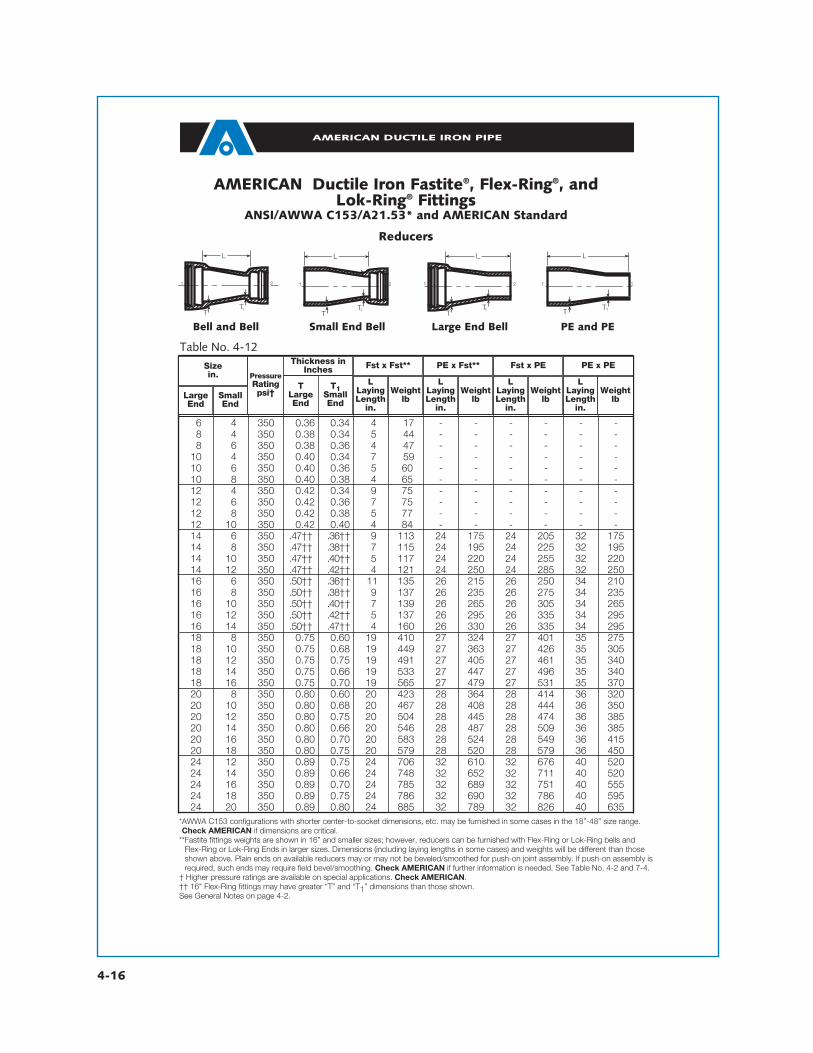
Table No. 4-12
16 14 350 0.36 0.34 14 117 - - - - - -18 14 350 0.38 0.34 15 144 - - - - - -18 16 350 0.38 0.36 14 147 - - - - - -10 14 350 0.40 0.34 17 159 - - - - - -10 16 350 0.40 0.36 15 60 - - - - - -10 18 350 0.40 0.38 14 65 - - - - - -12 14 350 0.42 0.34 19 75 - - - - - -12 16 350 0.42 0.36 17 75 - - - - - -12 18 350 0.42 0.38 15 77 - - - - - -12 10 350 0.42 0.40 14 84 - - - - - -14 16 350 .47†† .36†† 19 113 24 175 24 205 32 17514 18 350 .47†† .38†† 17 115 24 195 24 225 32 19514 10 350 .47†† .40†† 15 117 24 220 24 255 32 22014 12 350 .47†† .42†† 14 121 24 250 24 285 32 25016 16 350 .50†† .36†† 11 135 26 215 26 250 34 21016 18 350 .50†† .38†† 19 137 26 235 26 275 34 23516 10 350 .50†† .40†† 17 139 26 265 26 305 34 26516 12 350 .50†† .42†† 15 137 26 295 26 335 34 29516 14 350 .50†† .47†† 14 160 26 330 26 335 34 29518 18 350 0.75 0.60 19 410 27 324 27 401 35 27518 10 350 0.75 0.68 19 449 27 363 27 426 35 30518 12 350 0.75 0.75 19 491 27 405 27 461 35 34018 14 350 0.75 0.66 19 533 27 447 27 496 35 34018 16 350 0.75 0.70 19 565 27 479 27 531 35 37020 18 350 0.80 0.60 20 423 28 364 28 414 36 32020 10 350 0.80 0.68 20 467 28 408 28 444 36 35020 12 350 0.80 0.75 20 504 28 445 28 474 36 38520 14 350 0.80 0.66 20 546 28 487 28 509 36 38520 16 350 0.80 0.70 20 583 28 524 28 549 36 41520 18 350 0.80 0.75 20 579 28 520 28 579 36 45024 12 350 0.89 0.75 24 706 32 610 32 676 40 52024 14 350 0.89 0.66 24 748 32 652 32 711 40 52024 16 350 0.89 0.70 24 785 32 689 32 751 40 55524 18 350 0.89 0.75 24 786 32 690 32 786 40 59524 20 350 0.89 0.80 24 885 32 789 32 826 40 635
Sizein. Pressure
Ratingpsi†
Thickness inInches Fst x Fst** PE x Fst** Fst x PE PE x PE
LLayingLength
in.
LLayingLength
in.
LLayingLength
in.
LLayingLength
in.
Weightlb
Weightlb
Weightlb
Weightlb
TLargeEnd
T1SmallEnd
LargeEnd
SmallEnd
AMERICAN Ductile Iron Fastite®, Flex-Ring®, and Lok-Ring® Fittings
ANSI/AWWA C153/A21.53* and AMERICAN Standard
Reducers
*AWWA C153 configurations with shorter center-to-socket dimensions, etc. may be furnished in some cases in the 18”-48” size range.Check AMERICAN if dimensions are critical.
**Fastite fittings weights are shown in 16” and smaller sizes; however, reducers can be furnished with Flex-Ring or Lok-Ring bells and Flex-Ring or Lok-Ring Ends in larger sizes. Dimensions (including laying lengths in some cases) and weights will be different than thoseshown above. Plain ends on available reducers may or may not be beveled/smoothed for push-on joint assembly. If push-on assembly isrequired, such ends may require field bevel/smoothing. Check AMERICAN if further information is needed. See Table No. 4-2 and 7-4.
† Higher pressure ratings are available on special applications. Check AMERICAN.†† 16" Flex-Ring fittings may have greater “T” and “T1” dimensions than those shown.See General Notes on page 4-2.

4-17
AMERICAN DUCTILE IRON PIPE
TT
L
21
1
Bell and Bell
TT
L
21
1T
T
L
21
1 TT
L
21
1
Small End Bell Large End Bell PE and PEBell and Bell Small End Bell Large End Bell PE and PE
Table No. 4-12 —Continued
*AWWA C153 configurations with shorter center-to-socket dimensions, etc. may be furnished in some cases in the18”-48” size range. Check AMERICAN if dimensions are critical.
**Fastite fitting weights are shown in 16” and smaller sizes; however, reducers can be furnished with Flex-Ring or Lok-Ringbells and Flex-Ring or Lok-Ring Ends in larger sizes. Dimensions (including laying lengths in some cases) and weights willbe different than those shown above. Plain ends on available reducers may or may not be beveled/smoothed for push-onjoint assembly. If push-on assembly is required, such ends may require field bevel/smoothing. See Table No. 4-2 and 7-4.
† Higher pressure ratings are available on special applications. Check AMERICAN.See General Notes on page 4-2.
30 12 250 1.03 0.75 30 1910 38 1775 38 1910 46 177530 14 250 1.03 0.66 30 1940 38 1805 38 1905 46 177030 16 250 1.03 0.70 30 1985 38 1850 38 1945 46 181030 18 250 1.03 0.75 30 1030 38 1895 38 1995 46 186030 20 250 1.03 0.80 30 1080 38 1945 38 1045 46 191030 24 250 1.03 0.89 30 1210 38 1075 38 1150 46 101536 20 250 1.15 0.80 36 1490 44 1280 44 1455 52 125036 24 250 1.15 0.89 36 1635 44 1425 44 1575 52 136536 30 250 1.15 1.03 36 1925 44 1715 44 1790 52 158042 20 250 1.28 0.80 42 1710 50 1700 50 1680 58 167042 24 250 1.28 0.89 42 1875 50 1865 50 1815 58 180042 30 250 1.28 1.03 42 2200 50 2185 50 2065 58 205042 36 250 1.28 1.15 42 2540 50 2525 50 2330 58 232048 24 250 1.42 0.89 48 2430 56 2400 56 2370 64 234048 30 250 1.42 1.03 48 2790 56 2760 56 2655 64 262548 36 250 1.42 1.15 48 3170 56 3140 56 2960 64 293048 42 250 1.42 1.28 48 3315 56 3285 56 3305 64 327554 30 250 0.90 1.00 31.25 2035 41.25 1810 39.25 1900 49.25 167554 36 250 0.90 1.15 27.25 2180 37.25 1960 35.25 1975 45.25 175054 42 250 0.90 1.25 19.25 1850 29.25 1630 27.25 1840 37.25 161554 48 250 0.90 1.40 15.25 1890 25.25 1665 23.25 1860 33.25 163560 30 250 0.94 1.00 35.5 2345 45.5 2090 43.5 2210 53.5 195560 36 250 0.94 1.15 31.5 2505 41.5 2250 39.5 2300 49.5 204060 42 250 0.94 1.25 23.5 2175 33.5 1920 31.5 2165 41.5 191060 48 250 0.94 1.40 19.5 2230 29.5 1975 27.5 2200 37.5 194560 54 250 0.94 0.90 10.25 1815 20.25 1560 20.25 1590 30.25 133564 30 250 0.99 1.00 39.25 2690 49.25 2390 47.25 2555 57.25 225564 36 250 0.99 1.15 35.25 2860 45.25 2565 43.25 2655 53.25 235564 42 250 0.99 1.25 27.25 2525 37.25 2230 35.25 2515 45.25 221564 48 250 0.99 1.40 23.25 2590 33.25 2295 31.25 2560 41.25 226564 54 250 0.99 0.90 14.5 2145 24.5 1845 24.5 1920 34.5 162564 60 250 0.99 0.94 10.25 2050 20.25 1750 20.25 1795 30.25 1495
Sizein. Pressure
Ratingpsi†
Thickness inInches Fst x Fst** PE x Fst** Fst x PE PE x PE
LLayingLength
in.
LLayingLength
in.
LLayingLength
in.
LLayingLength
in.
Weightlb
Weightlb
Weightlb
Weightlb
TLargeEnd
T1SmallEnd
LargeEnd
SmallEnd
AMERICAN Ductile Iron Fastite®, Flex-Ring®, and Lok-Ring® Fittings
ANSI/AWWA C153/A21.53* and AMERICAN Standard
Reducers

4-18
AMERICAN DUCTILE IRON PIPE
4"-12"14"-54"
TT
4"-12"* 14"-54"*
Table No. 4-13
14 350 - 11- - -16 350 - 11- - -18 350 - 11- - -10 350 0.87 11- - -12 350 0.87 11- - -14 350 - 1- 1- -16 350 - 1- 1180 -18 350 - 1- 1220 -20 350 - 1- 1290 -24 250†† 1.16 1350 1440 -30 250 1.37 1565 1620 -36 250 1.58 1785 1050 -42 250 1.78 1355 1270 -48 250 1.96 1670 1800 -54 250 2.16 2415 - 180460 250 2.50 2680 - 241764 250 2.75 3230 - 2865
Sizein.
Pressure†Rating
psi
Tin. Fastite* or
Push-On Flex-Ring Lok-Ring
T
Fastite Plugs
Max. Tap Sizewithout Boss
TT T
4"-12" 14"-24" 36"-42"
Weight in Pounds
American Ductile Iron Fastite®, Flex-Ring®, and Lok-Ring® Fittings
American StandardPlugs
† Higher pressure ratings are available on special applications. Check AMERICAN.†† 24” Flex-Ring Plug is rated 350 psi.*All 4”-20” Fastite or Push-On plugs are furnished with internal set-screw restraint. See Table No. 4-13 for descriptions and ratings.
Fast-Grip® gaskets should not be used with Fastite plugs if disassembly would ever be required.Standard Fastite Plugs 30”-54” are satisfactory for tapping up through 2" NPT. For larger taps in these sizes and for all size taps on 24”size, plugs are furnished with special boss, when specified. Except as noted below, taps are furnished only when specified.
Steel eyebolts with 1” or 11⁄2” NPT male pipe threads can be obtained from AMERICAN to be threaded into these standard tappedholes to aid in non-destructive plug removal (pulling or jacking) operations.
14”-64” Lok-Ring and Flex-Ring plugs have one 1” (14”-24” sizes) or one 11⁄2” (30”-64” sizes) boss and tap (plugged) at invert andlifting eyes 180° from the boss. These taps facilitate testing and disassembly. If a different size or location of taps is required, it must bespecified.
See General Notes on page 4-2.
48"-64" Lok-Ring Plugs
Flex-Ring Plugs
4-19
AMERICAN DUCTILE IRON PIPE
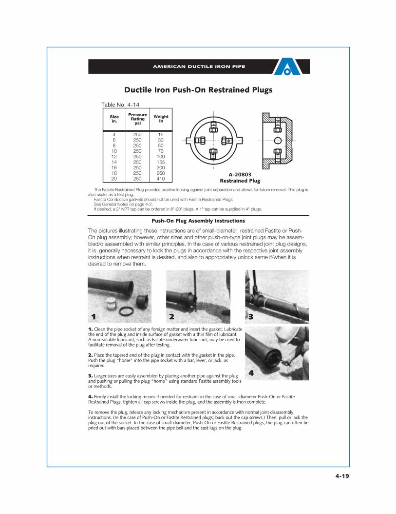
Ductile Iron Push-On Restrained Plugs
T
A-20803Restrained Plug
The Fastite Restrained Plug provides positive locking against joint separation and allows for future removal. This plug isalso useful as a test plug.
Fastite Conductive gaskets should not be used with Fastite Restrained Plugs.See General Notes on page 4-2.If desired, a 2" NPT tap can be ordered in 6"-20" plugs. A 1" tap can be supplied in 4" plugs.
Push-On Plug Assembly Instructions
1. Clean the pipe socket of any foreign matter and insert the gasket. Lubricatethe end of the plug and inside surface of gasket with a thin film of lubricant. A non-soluble lubricant, such as Fastite underwater lubricant, may be used tofacilitate removal of the plug after testing.
2. Place the tapered end of the plug in contact with the gasket in the pipe.Push the plug “home” into the pipe socket with a bar, lever, or jack, asrequired.
3. Larger sizes are easily assembled by placing another pipe against the plugand pushing or pulling the plug “home” using standard Fastite assembly toolsor methods.
4. Firmly install the locking means if needed for restraint in the case of small-diameter Push-On or FastiteRestrained Plugs, tighten all cap screws inside the plug, and the assembly is then complete.
To remove the plug, release any locking mechanism present in accordance with normal joint disassemblyinstructions. (In the case of Push-On or Fastite Restrained plugs, back out the cap screws.) Then, pull or jack theplug out of the socket. In the case of small-diameter, Push-On or Fastite Restrained plugs, the plug can often bepried out with bars placed between the pipe bell and the cast lugs on the plug.
1 2 3
4
4 250 156 250 308 250 50
10 250 7012 250 10014 250 15516 250 20018 250 26020 250 410
Table No. 4-14
Sizein.
PressureRating
psi
Weightlb
The pictures illustrating these instructions are of small-diameter, restrained Fastite or Push-On plug assembly; however, other sizes and other push-on-type joint plugs may be assem-bled/disassembled with similar principles. In the case of various restrained joint plug designs,it is generally necessary to lock the plugs in accordance with the respective joint assemblyinstructions when restraint is desired, and also to appropriately unlock same if/when it isdesired to remove them.

4-20
AMERICAN DUCTILE IRON PIPE
Table No. 4-15
14 350 0.75 1121 - -16 350 0.75 1133 - -18 350 0.75 1151 - -10 350 0.75* 1167 - -12 350 0.75* 1186 - -14 250†† 0.82 1122 1- -16 250†† 0.89 1159 1273 -18 250†† 0.96 1194 1341 -20 250†† 1.03 1242 1429 -24 250†† 1.16 1356 1611 -30 250 1.37 1617 1894 -36 250 1.58 1947 1321 -42 250 2.25 1712 2190 -48 250 2.38 2340 2625 -54 250 2.43 3122 - 330760 250 2.50 3615 - 385364 250 2.75 4328 - 4554
Sizein.
Pressure†Rating
psi
Tin.
Fastite** Flex-Ring Lok-Ring
Weight in Pounds
TTT
4"-20" 42"-64"24"-36"
T
48"-54" Lok-Ring Caps
T
16"-42" Flex-Ring Caps
T T
AMERICAN Ductile Iron Fastite®, Flex-Ring®, and Lok-Ring® Fittings
AMERICAN StandardCaps
† Higher pressure ratings are available on special applications. Check AMERICAN.†† 14”-24” Flex-Ring Caps are rated 350 psi.*T dimension for Flex-Ring Cap in 10” and 12” sizes is .87.Standard Fastite Caps 4”-12” and 30”-54” are satisfactory for tapping up through 2” NPT. For larger taps in these
sizes and for all size taps on 14”-24” sizes, caps are furnished with special boss, when specified. Except as noted below,taps are furnished only when specified.
14”-64” Lok-Ring and Flex-Ring caps have one 1” (14”-24” sizes) or one 11⁄2” (30”-64” sizes) boss and tap (plugged) atinvert and lifting eyes 180° from the boss. These taps facilitate testing and disassembly. If different size or location of tapsis required, it must be specified.
See General Notes on page 4-2.** 4”-24” Caps may be Fastite or other Push-On joint.
Fastite Caps

4-21
ASSEMBLY OF LOK-RING® PLUGS
T
Typical Lok-Ring Plug
NOTE: A Lok-Ring plug, in effect, simulates the spigot end of a Lok-Ring pipe orfitting, with the outside face of the plug “bulkhead” plate roughly even with the bear-ing face of the plug abutment (simulating the weld ring on a pipe end). The Lok-Ringplug is normally shipped with the Lok-Ring bolted down (in effect, “backwards”) onthe beveled plain end barrel of the plug. This Lok-Ring is completely removed prior toinsertion of the plug completely up inside a socket, then the Lok-Ring is inserted andspread completely into the socket locking groove (in effect, “behind” the plug) torestrain it in the socket.
Assembly Instructions:
1. Remove (unbolt) the Lok-Ring completely off the plug by wrenching or manipu-lating only the outside closure nut opposite the “locked” (nut) side of the closure mech-anism.
2. Prepare spigot and sockets, insert gasket, and lubricate the plug spigot end andgasket in accordance with basic Fastite (and Lok-Ring) joint assembly instructions. Seepage 2-10.
3. Push or pull the plug completely up inside the socket. Due to the “short” natureof the push-on joint plug, some means is normally necessary to stabilize or brace theplug so that it does not pivot or “buck sideways” in joint assembly. A longer pipe, theend of which can be placed against the outside face of the plug, or a (large bearingface) timber braced between the plug face and the flat lower face of a backhoe bucketare normally quite effective for this purpose. Of course, if the end of a pipe is used topush the plug in, any conventional pipe assembly means could be used to pull or pushthe pipe and the plug into the socket. Sufficient socket locking groove “width” shouldbe clearly visible after pushing the plug up inside the socket to allow insertion of theLok-Ring.
4. Compress the ends of the loose Lok-Ring together and push it ccoommpplleetteellyy intothe socket locking groove to restrain the plug in the socket.
5. Wrenching only the inside spreader nut opposite the locked side of the closuremechanism, mechanically spread the Lok-Ring into firm contact with the inner socketsurface of the socket locking groove.
6. Inspect the installed Lok-Ring making sure that the ring is completely inserted inthe socket locking groove and completely restrained by the socket restraint lip from oneend of the ring to the other end all around the joint. If the ring is out of the groove atany point, correct this condition prior to applying any pressure load to the plug.
AMERICAN DUCTILE IRON PIPE

4-22
AMERICAN DUCTILE IRON PIPE
4”-16” PUSH-ON FITTING ASSEMBLY INSTRUCTIONS*
ASSEMBLY INSTRUCTIONSAssembling AMERICAN Fastite®, Lok-Ring®, and Flex-Ring® fittings is simple. It is very
similar to the assembly of Fastite pipe shown in Section 2. (For instructions on completeassembly of Fast-Grip®, Flex-Ring, Field Flex-Ring®, and Lok-Ring joints, check Section 9.)Fast-Grip gaskets may be used in lieu of standard Fastite gaskets in the bells of same size (4"-30") Fastite and Flex-Ring joint pipe and fittings where easy, field-adaptable restraint isdesired in pipelines with working pressure from 150-350 psi, depending on size. No Flex-Ringrestraining mechanism is necessary when using Fast-Grip gaskets in Flex-Ring bells.
Push-on fittings may be assembled on individual pipe aboveground, or assembled ontothe pipeline belowground. Many installers, however, do prefer to pull restrained joint fittings,in particular Fast-Grip, Flex-Ring, etc., onto a piece of pipe aboveground. This is sometimesaccomplished by simply bracing one end of the pipe against a heavy piece of equipment (e.g.backhoe) and pulling the fitting onto the far end of the pipe using the method shown below.Then the pipe and fitting can be lowered as a single unit into the trench. Fastite fittings maybe assembled aboveground if a situation arises which would make trench assembly difficult.However, in this case the assembly yokes and pulling sling must be kept safely in place andthe sling must remain taut while the Fastite assembly is lowered into the ground. This shouldprevent the Fastite fitting from slipping off the end of the pipe.
While it may be possible to “rotate” some push-on fittings (after they are assembled to fixed/in-situ piping), AMERICAN recommends that fittings be assembled in their actual service orientation.
NOTES:*Larger-diameter fittings which cannot be assembled with equipment shown may be assembled using a similar proce-
dure with heavier or stronger field rigging and more powerful equipment. (See example photo on page 4-24.)
1. CLEANING OF SOCKET AND SPIGOTClean the socket and plain end of the
pipe thoroughly, removing mud, sand, grav-el, ice, frozen material, or other matter whichcould prevent a proper joint seal. Material inthe gasket grooves may cause the gasket toprotrude into the path of the entering spigot.Therefore, iitt iiss iimmppoorrttaanntt tthhaatt aallll jjooiinnttrreecceesssseess bbee kkeepptt cclleeaann dduurriinngg iinnsseerrttiioonn oofftthhee ggaasskkeett aanndd aasssseemmbbllyy ooff tthhee jjooiinntt ttoo pprree--vveenntt ggaasskkeett ddiissllooddggmmeenntt aanndd//oorr ssuubbsseeqquueennttlleeaakkaaggee..2. PLACEMENT OF GASKET
Wipe the gasket clean. After flexing oneor more “loops” in the gasket, insert the gas-ket in the gasket recess of the socket with thelarge sealing end of the gasket toward therear of the socket (Photo 1). If Fast-Grip gas-kets are used, the center of the gasket loopsshould bep o s i t i o n e dbetween toothl o c a t i o n s .Press the gas-ket into themating socketrecesses so themetal-carrying
retainer end of the gasket is seated complete-ly and uniformly in the socket groove. Takecare that no gasket loops or bulges protrudeinto the path of the entering pipe spigot. Inextremely cold weather conditions, gasketsshould be warmed before installing.3. LUBRICATION OF THE JOINT
With a clean brush, apply a liberalamount of regular Fastite lubricant complete-ly over the exposed inner surface of the gas-ket after it is placed in the socket (Photo 2).Also, apply lubricant completely over theplain end of the pipe, the spigot radius, andthe outer surface of the pipe up to theassembly stripe (Photo 3). Use only lubricantprovided by AMERICAN. For underwater orvery wet conditions, special AMERICANunderwater lubricant is recommended and isavailable upon request. This special lubricant
for under-water ser-vice is rela-tively insolu-ble in waterimmers ionor exposureto flowingwater.1 2

4-23
AMERICAN DUCTILE IRON PIPE
4”-16” PUSH-ON FITTING ASSEMBLY INSTRUCTIONS
ASSEMBLY INSTRUCTIONS Continued
4. INITIAL PLACEMENT OF BEVELEND INTO SOCKET†
The spigot end of the pipe should be inreasonably straight alignment when enteredin the socket. Center the spigot in theinstalled gasket, so it makes firm and evencontact withthe inner sur-face of thegasket. Donot place pipes p i g o t i nsocket whilein a substan-tially deflect-ed position.5. ASSEMBLY OF LUGGED FITTINGSAND OPTIONAL USE OF YOKES
4"-12" Fastite fittings may normallythen be pulled readily onto pipe ends byfirst firmly supporting the fitting in alignedassembly position, and then pulling on thecenter of a wire rope or chain sling attachedto the fitting lugs with any suitable pullingmechanism (such as a backhoe, come-along, pry bar, etc.) as in Photo 4 until thespigot is fully inserted into the socket.However, ifany difficultiesin assemblywith availablerigging areencounteredwith any 4"-16" push-onjoint fittings,special steela s s e m b l yyokes, customw i r e r o p es l i n g s , a n dcome-alongsin all 4"-16"s i z e s a r eavailable from
AMERICAN. The simple placement of oneof the semi-circular steel yokes under thespigot end about 3 or 4 inches back fromthe spigot stripe and the placement of awire rope or chain sling through the yokeand attached to the lugs of 4"-12" Fastitefittings as in Photo 5 assures that the pullingforce is applied where it is most effectiveand straight at the springline of the joint.6. ASSEMBLY OF YOKES
Special steel assembly yokes and slingsare particularly helpful in the assembly of4"-16" Flex-Ring and 14"-16" Fastite fit-tings, which are standardly furnished with-out lugs. Such yokes are available fromAMERICAN for assembly of all sizes 4"-16"push-on joint fittings. Place one of theseyokes just beyond the bell end of the fitting
which is con-nected to thepipe. (It maybe necessaryto tap theyoke with ahammer.) Theyoke shouldbe on the topside of the fit-ting (Photo 6).Place a secondyoke under-n e a t h t h espigot pipeabout 3 or 4inches fromt h e s p i g o t
stripe, 180 degrees from the first yoke (Photo7). Put a wire rope sling (or other similardevice) underneath the fitting, thread thesling through the hooks of the second yoke,and connect the ends of the sling to thepulling mechanism (e.g. backhoe, pry bar,come-along with choker, etc.) as shown inPhotos 8 & 9.
3
6
7
† Joints using Fast-Grip gaskets should be assembled in proper orientation so as to avoid rotation of the fitting afterassembly. See Fast-Grip Gasket Assembly Instructions in Secton 9.
5
4

4-24
It is like-wise possibleto assembleeven largerdiameter fit-tings with field-made riggingsimilar in func-tion to thesmaller cus-tom steelyokes, butinstead usinga chain orwire ropesling, etc.,looped underthe spigot to,in similareffect, direct asingle pointpulling forceinto twopull ing sl inglegs straightat the spring-line. (SeePhoto 10.)7. COMPLETE ASSEMBLY OF PLAINEND INTO SOCKET
Pull the sling with smooth, steady forceuntil the fitting is “pulled up” and the plainend uniformly contacts the rear of the sock-et. It is best practice to make assembliessmoothly and progressively in one motion,without repeated “wobbling” (or jointdeflection) back and forth. Desired jointdeflection may then be set. Any abnormaljoint assembly loads or behavior, such asunexplained exposure of the assembly stripeoutside the bell, may indicate impropercleaning, gasket insertion, spigot placement,or lubrication. In any such case, it may beadvisable to feel for correct gasket position-ing by passing a thin (automotive or other)feeler gauge between the bell and spigot allaround the assembled joint. Any joint withapparent problems (pushed gasket locationsfound by the probe, etc.) should be disassem-
bled and corrected prior to filling or testingthe pipeline. (See Section 9 for disassemblyinvolving Fast-Grip gaskets or Field Flex-Rings.)DOUBLE FITTING ASSEMBLY
In areas involving short lengths of pipebetween two fittings, it may be desirable to
simultaneous-ly assemblethe two fit-tings onto asingle piece ofpipe. This maybe accom-plished withA M E R I C A Npush-on jointfittings due tothe self-cen-tering natureof the joints.
T h i s“double as-sembly” pro-cedure is simi-lar to the sin-gle fitt ingassembly pro-cedure men-tioned earlier.In fact, Steps1 through 4are identical.For Step 5,place one
yoke over the bell end of one of the fittingsas shown in Photo 4. Then, place the secondyoke under the bell of the other fitting(Photo 11). Attach a wire rope sling (orother similar device) to the yokes in a man-ner similar to Step 5 (Photo 12). Note thatboth yokes can also be placed on the bot-toms of the fittings for the same effect, ifdesired. Complete the assembly by simplypulling the ends of the sling with a pullingmechanism as in Step 5.
Another method for the “doubleassembly” may be more convenient forpipes of sufficient length and any in-trench
AMERICAN DUCTILE IRON PIPE
4”-16” PUSH-ON FITTING ASSEMBLY INSTRUCTIONS
ASSEMBLY INSTRUCTIONS-Continued
8
9
11
12
13
10

4-25
AMERICAN DUCTILE IRON PIPE
4”-16” PUSH-ON FITTING ASSEMBLY INSTRUCTIONS
ASSEMBLY INSTRUCTIONS-Continued
applications where there may not be easymeans for sufficient bracing of the fitting.This method involves the use of twocome-alongs (one on each side of thepipe) in order to provide a reasonablysteady, evenly distributed assembly force.The assembly procedure is similar to thepreviously mentioned procedure. Placeyokes on the fittings in the same manneras the other “double assembly” proce-dure (Photo 9). Then, place one shortassembly sling under each of the twofittings and attach the sling to the yokes.Position the come-alongs on each side ofthe assembly and attach the sling thimblesor loops to both sides of the come-alongs(Photo 13). Work the come-alongssimultaneously to make a smooth, evenassembly.FIELD-CUT PIPE
When pipe is cut in the field, the cut
end must be properly prepared prior toassembly into the push-on socket. Using aportable grinder, place an approximately1/4” to 1/2” long smooth assemblychamfer or bevel on the outside end of thepipe. This bevel should make an angle of30-40° with the axis of the pipe. Careshould be taken to ensure that all cornersare rounded and no sharp or rough edgesremain that might damage or dislodge thegasket. Finally, it is good practice to markat least a rough assembly stripe on thenewly beveled pipe. The distance from thebeveled end of the pipe to the oppositeedge of the stripe should be about 1/8”less than the socket depth. (See Table No.4-1 for typical socket depths of pipe or fit-tings, or measure same in the field.) Thisstripe is helpful in confirming proper jointinsertion and also as an indication of jointdeflection.
FIELD RIGGING EXAMPLE
Assembly of a larger push-on joint fitting.
NOTES:*Larger-diameter fittings which cannot be assembled with equipment shown may be assembled using a similar procedure with heavier or stronger field rigging and more powerful equipment. (See example photos above.)Final restrained joint pipe/fitting assemblies (connections to previously installed/fixed piping) should beassembled in proper orientation so as to avoid rotation of the fitting after assembly. See Fast-Grip GasketAssembly Instructions in Restrained Joint Pipe (Section 9).

®
AMERICAN DUCTILE IRON PIPE
AMERICAN reserves the right to modify or change designs, materials, specifications, or dimensions shown herein without prior notice.
This is a revised reprint of a section from the 19th Edition of the AMERICAN PipeManual. References may be made in this section to other sections of this manual.
APM4—REV—06-07Litho in USA


