
Second M.A.Sc. Seminar: A System-on-Chip Fibre Channel IP ...
27
Research Centre for Integrated Microsystems W I N D S O R U N I V E R S I T Y O F Second M.A.Sc. Seminar: A System-on-Chip Fibre Channel IP Core Till Kuendiger Research Centre for Integrated Microsystems Electrical and Computer Engineering Till K¨ undiger M.A.Sc. Seminar - Slide 1 June 2004
Transcript of Second M.A.Sc. Seminar: A System-on-Chip Fibre Channel IP ...

Research Centre for Integrated Microsystems W I N D S O RU N I V E R S I T Y O F
Second M.A.Sc. Seminar:A System-on-Chip Fibre Channel IP Core
Till Kuendiger
Research Centre for Integrated Microsystems
Electrical and Computer Engineering
Till Kundiger M.A.Sc. Seminar - Slide 1 June 2004

Research Centre for Integrated Microsystems W I N D S O RU N I V E R S I T Y O F
Overview
Thesis Goal : Design and implement a Fibre Channel soft IPcore which may be used in future high performance
System-On-Chip designs
Presentation Overview
1. SoC communication overview
2. Fibre channel data structures
3. Fibre channel level 1 topology and functionality
4. Fibre channel level 2 functionality
5. Design Architecture and implementation considerations
Till Kundiger M.A.Sc. Seminar - Slide 2 June 2004

Research Centre for Integrated Microsystems W I N D S O RU N I V E R S I T Y O F
Fibre Channel Overview
What is Fibre Channel?
An integrated set of protocols developed by ANSI for managing data flow, does not
require it’s own command set
Provides a high speed serial link between a wide variety of different FC Nodes
Allows for a variety of topologies:
Point-to-Point
Arbitrated Loop
Switched Fabric
Aims to combine traditional storage I/O with network functionality:
High speeds and low latency
A large number of allowable nodes (up to thousands of interconnected nodes)
Support multiple network and storage protocols
Scalable open industry standard
Defined in five levels: FC-0 → FC-4 (physical specification to user level protocol)
Till Kundiger M.A.Sc. Seminar - Slide 3 June 2004

Research Centre for Integrated Microsystems W I N D S O RU N I V E R S I T Y O F
Traditional SoC ASIC
Front Side BusInternal Bus Internal Bus
IPCore
IPCore
IPCore
IPCoreIP
CoreCoreIP Core
IP
CoreIP
CoreIP
CoreIP
A modern ASIC with several core components has an internal communication mechanism
which is typically isolated and independent from the chip’s I/O functionality
Off-chip communication is usually handled on a case by case bases
A Fibre Channel port SoC core would allow for a more standardized communications
architecture which could be used for a wide variety of systems
Till Kundiger M.A.Sc. Seminar - Slide 4 June 2004

Research Centre for Integrated Microsystems W I N D S O RU N I V E R S I T Y O F
SoC Bus Comparison
1. ARM Amba: A straight forward bus system for basic SoC functionality. Provides two
performance bus options (AHB and ASP) and one peripheral bus specification.
APB
AHB or ASP
UART Timer
CPU
Bridge DMA
ArbiterRAM
Widely adopted in industry
Limited in flexibility due to uncertainties in specification
Till Kundiger M.A.Sc. Seminar - Slide 5 June 2004

Research Centre for Integrated Microsystems W I N D S O RU N I V E R S I T Y O F
2. IBM CoreConnect: A technically advanced bus system which strictly defines how all
components connect to one another. Defines specifications for all building blocks: PLB,
OPB, DRC and Arbiter.
PLBDRC
OPB
TimerUART
External BusI/O
Arbiter
Bridge DMA
ArbiterCPU RAM
Very advanced complete/flexible bus communication system
High complexity/implementation overhead
Till Kundiger M.A.Sc. Seminar - Slide 6 June 2004

Research Centre for Integrated Microsystems W I N D S O RU N I V E R S I T Y O F
3. Silicore/OpenCores Wishbone: An very simple architecture with only a single high
performance bus specification. Wishbone is extremely flexible in its implementation.
WISHBONE
RAMCPU
DMAArbiter
High performance with low complexity
Allows designer to implement several identical bus’ in order to meat requirements of
peripheral and CPU/performance throughput.
Requires designer to provide any additional bridge circuitry which might be needed
Till Kundiger M.A.Sc. Seminar - Slide 7 June 2004

Research Centre for Integrated Microsystems W I N D S O RU N I V E R S I T Y O F
Fibre Channel for SoC
Combining Fibre Channel connectivity with a SoC bus architecture wouldallow an ASIC designer to easily implement functional blocks acrossseveral different dies as needed
The flexibility and high performance nature of the Wishbone SoC Busmakes it an ideal candidate for a FC interface implementation
Till Kundiger M.A.Sc. Seminar - Slide 8 June 2004

Research Centre for Integrated Microsystems W I N D S O RU N I V E R S I T Y O F
Transmission Characters & Words
There are two types of transmission characters:
Data characters; Dxx.y
Special characters; Kxx.y
The value xx is determined by bits 0→ 4 of the 8-bit value; the value y is determined
by bits 5→ 7; Whether the character is K or D character is decided externally
A running disparity is calculated for each transmission charactersent/received
The smallest amount of information which may be transfered is onetransmission word which consists of four transmission characters; 40-bitsrepresenting 32-bits of data
A transmission word starting with a special (K) character is anOrdered Set
All data words are transmitted within a Fibre Channel Frame as part of aSequence
Till Kundiger M.A.Sc. Seminar - Slide 9 June 2004

Research Centre for Integrated Microsystems W I N D S O RU N I V E R S I T Y O F
Ordered Sets
Primitive Signal
Fill Word
Primitive Sequence
Non−Fill Word
Frame Delimiter
Data Word
Ordered Set
Transmision Word
Frame Delimiters mark the beginning and end of a frame
Fill Words are sent between frames and are used for character alignment
Non-Fill Words have assorted functionality
Primitive Sequences are used for link services
Till Kundiger M.A.Sc. Seminar - Slide 10 June 2004

Research Centre for Integrated Microsystems W I N D S O RU N I V E R S I T Y O F
The Fibre Channel Frame
WordsWords1 6
WordWord1 1
Wordup to 528
SOF Data Payload CRC EOFFrame Header
The frame header contains:
R CTL: Routing Control
D ID: Destination Identification
CS CTL: Class Specific Control and
Priority
S ID: Source Identification
TYPE: Data Structure Type
F CTL: Frame Control
SEQ ID: Sequence Identification
SEQCNT: Sequence Count
OX ID: Originator Exchange
Identification
RX ID: Responder Exchange
Identification
Parameter: Context Sensitive
Condition Parameters
Till Kundiger M.A.Sc. Seminar - Slide 11 June 2004

Research Centre for Integrated Microsystems W I N D S O RU N I V E R S I T Y O F
FC-1: A Fibre Channel Port
FC-1 defines most of the functionality for the low level implementation of aFibre Channel Port.
Every Fibre Channel Node (device on a FC network) has one or moreFC Ports
There are two fundamental types of ports: Nx Ports and F Ports;Nx Ports represent ports on FC Nodes, F Ports represent Fabric Ports
Provides three major functions
Data alignment; bit, byte and word alignment
Data encoding; 8b/10b encoding
Low-Level link protocols
Till Kundiger M.A.Sc. Seminar - Slide 12 June 2004
Research Centre for Integrated Microsystems W I N D S O RU N I V E R S I T Y O F
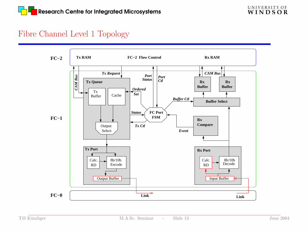
Fibre Channel Level 1 Topology
PortCtl
Status
Ordered
Event
FC PortFSM
Set
LinkLink
Rx RAMFC−2 Flow ControlFC−2
FC−1
FC−0
CAM BusC
AM
Bus
Buffer Ctl
Tx Ctl
Tx Request
StatusPort
RxBuffer
RxBuffer
Buffer Select
Rx Port
RxCompare
Tx Queue
Tx RAM
Tx Port
Output
Decode
BufferTx
Calc. 8b/10bEncode
Output Buffer
RDCalc.RD
Input Buffer
8b/10b
Cache
Select
Till Kundiger M.A.Sc. Seminar - Slide 13 June 2004

Research Centre for Integrated Microsystems W I N D S O RU N I V E R S I T Y O F
Module Overview
The modules required for FC-1 implementation:
Port FSM:
The main control logic for the port including link services/initialization and an interface
to FC-2
Transmit Queue:
Multiplexes frame data and primitive signals to the transmit port, inserts inter-frame
fill words
Transmit Port:
Encodes data words into transmission characters and calculates transmit running disparity
Receive Port:
Decodes serial link data, aligns data and calculates receiver running disparity
Receive Compare:
Handles received ordered sets
Receive Buffer/Buffer Select:
Stores received frames until they have been processed by FC-2
Till Kundiger M.A.Sc. Seminar - Slide 14 June 2004

Research Centre for Integrated Microsystems W I N D S O RU N I V E R S I T Y O F
FC Port Link Service FSM
State Transmit Description
OL1 OLS primitive sequence OLS Transmit Sub-state: Entered on reset
OL2 LR primitive sequence OLS Received Sub-state: Entered when OLS is received
OL3 NOS primitive sequence Wait for OLS Sub-state: Entered when Loss-of-Synch. is
detected
LF1 OLS primitive NOS Received Sub-state: Entered when NOS is received
LF2 NOS primitive sequence NOS Transmit Sub-state: Entered when link failure is
detected
LR1 LR primitive sequence LR Transmit Sub-state: Entered in order to begin link reset
LR2 LRR primitive sequence LR Received Sub-state: Entered when LR is received if not
waiting for OLS
LR3 IDLE LRR Received Sub-state: Entered when LRR is received from
AC/LR1/LR2/OL2 state
AC Frame data from transmit queue Active State: Normal transmit/receive operation
Till Kundiger M.A.Sc. Seminar - Slide 15 June 2004
Research Centre for Integrated Microsystems W I N D S O RU N I V E R S I T Y O F
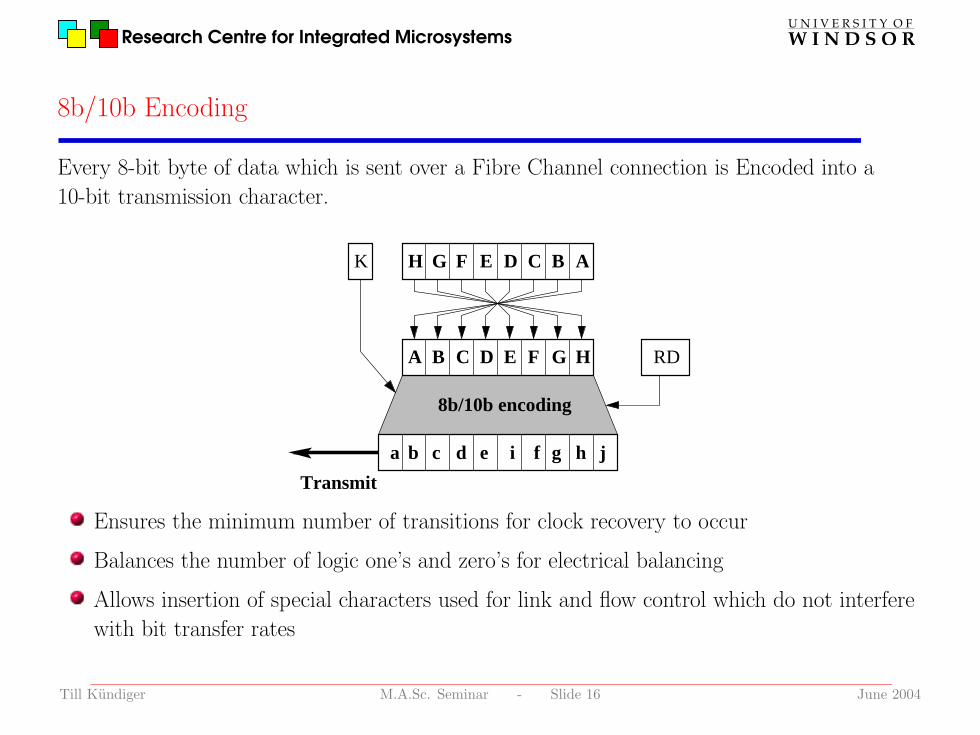
8b/10b Encoding
Every 8-bit byte of data which is sent over a Fibre Channel connection is Encoded into a
10-bit transmission character.
Transmit
b e f
RD
d
H
ca h ji g
K
8b/10b encoding
DH G F BE C A
A B C D E F G
Ensures the minimum number of transitions for clock recovery to occur
Balances the number of logic one’s and zero’s for electrical balancing
Allows insertion of special characters used for link and flow control which do not interfere
with bit transfer rates
Till Kundiger M.A.Sc. Seminar - Slide 16 June 2004

Research Centre for Integrated Microsystems W I N D S O RU N I V E R S I T Y O F
Data Stream De-Serialization
Character
Synch.
b a
Meta
Link
1.0625 GHz
Latch
clock
c
32
Synch.Word
8 88
10 1010
Synch.
j h g f i e d
RegisterBuffer
RegisterBuffer
RegisterBuffer
clock106.25 MHz
Logic
Comma
Logic8b/10 DecodeWord Align.
Detect Logic
Till Kundiger M.A.Sc. Seminar - Slide 17 June 2004

Research Centre for Integrated Microsystems W I N D S O RU N I V E R S I T Y O F
Running Disparity Calculation
The running disparity (RD) is calculated for each transmission character in sub-blocks
Sub-block one: bits abcdei
Sub-block two: bits fghj
The RD at the beginning of sub-block one is the RD at the end of the previous
transmission character
The RD at the beginning of sub-block two is the RD at the end of sub-block one
The RD at the end of a sub-block is positive if:
The sub-block contains more logic ones than zeros
It is ’000111’ (for sub-block one) or ’0011’ (for sub-block two)
The RD at the end of a sub-block is negative if:
The sub-clock contains more logic zeros than ones
It is ’111000’ (for sub-block one) or ’1100’ (for sub-block two)
The RD remains unchanged otherwise
Till Kundiger M.A.Sc. Seminar - Slide 18 June 2004

Research Centre for Integrated Microsystems W I N D S O RU N I V E R S I T Y O F
Transmit Queue FSM
010011101
000
110
100001
Red: Transmit primitive signal
Cyan: Transmit fill word/Comma
Green: Transmit frame data
Till Kundiger M.A.Sc. Seminar - Slide 19 June 2004

Research Centre for Integrated Microsystems W I N D S O RU N I V E R S I T Y O F
Fibre Channel Level 2
FC-2 defines most of the advanced features and flexibility of Fibre Channel
Exchange management
Session login/logout
Flow control
Classes of service
Data segmentation
Some of these are easily integrated into a FC Port, whereas others requireexternal processing and/or resources
Easily integrated External Processing
Frame CRC-32 Checking Exchange Management
Buffer-to-Buffer Flow Control End-to-End Flow ControlReceive-Transmit Timeout Monitoring Frame Acknowledgement/Sequence Tracking
Connection TrackingData Segmentation/De-Segmentation
Till Kundiger M.A.Sc. Seminar - Slide 20 June 2004
Research Centre for Integrated Microsystems W I N D S O RU N I V E R S I T Y O F
Fibre Channel Port FC-2 Module Functionality
CRC-32: The header and body of each FC frame are checked with a cyclic redundancy
check performed once an entire frame has been received. The FC CRC follows the FDDI
MAC (Fiber Distributed Data Interface Media Access Control) specifications. The
following 32-bit polynomial is used:
X32 +X26 +X23 +X16 +X12 +X11 +X10 +X8 +X7 +X5 +X4 +X2 +X + 1
When a frame is being buffered in the transmit queue a CRC-32 check is performed on
the data and the calculated value is appended to the frame as it is sent.
Buffer-to-Buffer Flow Control: The FC port will keep track of the number of
receive buffers which the connected port has available and not send data until at least one
receive buffer is ready. Additionally, a R RDY primitive signal is generated whenever a
local receive buffer is free to be re-used.
Receive-Transmit Timeout: The port checks to ensure that the amount of time
which is spent in certain states during link service does not exceed the number of
milliseconds stored in the RTTOV register.
Till Kundiger M.A.Sc. Seminar - Slide 21 June 2004

Research Centre for Integrated Microsystems W I N D S O RU N I V E R S I T Y O F
Fibre Channel Port Architecture
Status
Event
FC PortFSM
PortStatus
Port
Buffer Ctl
RTTO Ctl
Ctl
Mixed Signal Link Interface
Link
SoC WishBone Interface
Ordered
Link
Tx Ctl
Tx Request
Set Flow Ctl
Buffer Select
Tx Port Rx Port
RxCompare
Tx Queue RxBuffer
RxBuffer
B−B Flow
CRC−32
Encode
Control CRC−32
Cache
Timer
SelectOutput
Decode8b/10b
Input Buffer
RDCalc.
RD
Output Buffer
8b/10bCalc.
TxBuffer
Receive−Transmit
Till Kundiger M.A.Sc. Seminar - Slide 22 June 2004

Research Centre for Integrated Microsystems W I N D S O RU N I V E R S I T Y O F
Fibre Channel Port Amoeba View
Artisan Sage-X standard cell
library implementation on TSMC
0.18µm process.
Overall size is approximately
2.2× 2.2mm
Cell area breakdown:
Combinational Area: 40%
Non-combinational
Area: 60%
Structural area breakdown:
Receive Buffers
Transmit Queue
Rx Port
Tx Port
Till Kundiger M.A.Sc. Seminar - Slide 23 June 2004

Research Centre for Integrated Microsystems W I N D S O RU N I V E R S I T Y O F
RAM Considerations
The size of RAM is the largest contributer to the overall size of the design.RTL synthized RAM does not provide a very high density.
Technology specific optimized RAM blocks will allow substantial areareduction.
Standard Cell Virage Custom-Touch
Synthesized TSMC u18 2P SHD r05
536x32 Frame RAM 1 029 653.86 µm2 34 2645.12 µm2
256x32 Ordered Set Cache 861 879.52 µm2 200 664.42 µm2
RTL RAM modules allow the design to be technology independent
Custom high density RAM blocks should be substituted whenever possible
Till Kundiger M.A.Sc. Seminar - Slide 24 June 2004

Research Centre for Integrated Microsystems W I N D S O RU N I V E R S I T Y O F
FC-2: Network Functionality
In addition to data segmentation and framing this level of the protocol stack is responsible for
most of the advanced networking functionality of Fibre Channel. The flow control which is
used may vary widely based on the class of service which is employed. A FC-Port must
support at least one class of service.
Class 1: Dedicated single connection; Established connections are guaranteed ensuring
maximum bandwidth and in order delivery
Class 2: Multiplexed connectionless; Data frames are multiplexed at frame boundaries,
in order delivery is not guaranteed, notification is guaranteed
Class 3: Connectionless datagram; Data frames are multiplexed at frame boundaries, in
order delivery is not guaranteed, notification is not guaranteed
Class 4: Virtual circuit fractional bandwidth connection; fractional bandwidth is
guaranteed, in order delivery of frames and notification is guaranteed
Class 6: Multicast connection; Guaranteed connections to multiple Nx Ports with in
order delivery and guaranteed notification. Bandwidth is limited/determined by the
number of connections
Till Kundiger M.A.Sc. Seminar - Slide 25 June 2004

Research Centre for Integrated Microsystems W I N D S O RU N I V E R S I T Y O F
FC-2 Implementation Considerations
The vast diversity of functionality which is possible with Fibre Channel makesa general purpose hardware implementation of FC-2 very difficult.Two possibilities exist:
Implementation of a CPU with associated firmware: This solution wouldrequire relatively large amounts of resources in terms of power, die areaand development time
Implementation of a small subset of the available features in order to meetspecific design requirements: This solution might mean that the finishedproduct is not fully Fibre Channel compliant for the purpose ofinteroperability
Till Kundiger M.A.Sc. Seminar - Slide 26 June 2004

Research Centre for Integrated Microsystems W I N D S O RU N I V E R S I T Y O F
Conclusions
A Fibre Channel port provides an easy and efficient communicationssystem for a System-on-Chip which gives a High-level Data Link Controllike interface with other System-on-Chip devices
Implementation of a general purpose Fibre Channel SoC Node allows forthe exploration of a full FC-4 user level protocol mapping for standardizedSystem-on-Chip inter-chip communication
The End
Till Kundiger M.A.Sc. Seminar - Slide 27 June 2004