SEC 1500 Gas Detector Instruction Manual - Gas Detection Equipment
24
1 SEC 1500 Gas Detector Instruction Manual
Transcript of SEC 1500 Gas Detector Instruction Manual - Gas Detection Equipment

1
SEC 1500 Gas Detector Instruction Manual
Sensor Electronics Corporation SEC 1500 Instruction Manual Email: [email protected]
1
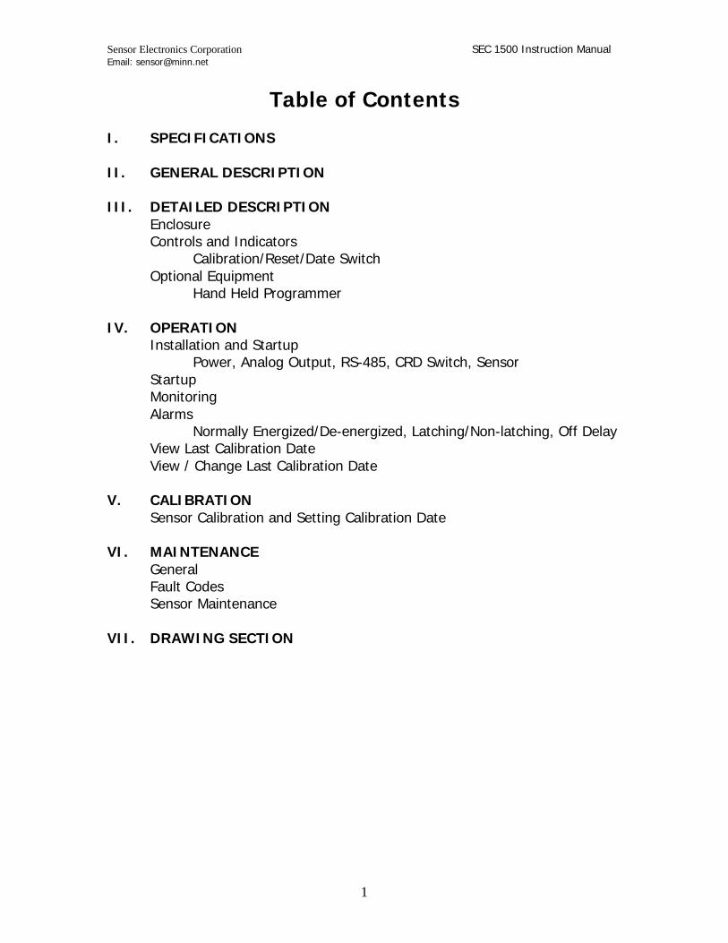
Table of Contents I. SPECIFICATIONS II. GENERAL DESCRIPTION III. DETAILED DESCRIPTION Enclosure Controls and Indicators Calibration/Reset/Date Switch Optional Equipment Hand Held Programmer IV. OPERATION Installation and Startup Power, Analog Output, RS-485, CRD Switch, Sensor Startup Monitoring Alarms Normally Energized/De-energized, Latching/Non-latching, Off Delay View Last Calibration Date View / Change Last Calibration Date V. CALIBRATION Sensor Calibration and Setting Calibration Date VI. MAINTENANCE General Fault Codes Sensor Maintenance VII. DRAWING SECTION
Sensor Electronics Corporation SEC 1500 Instruction Manual Email: [email protected]
2
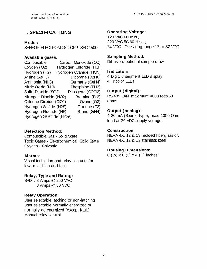
I. SPECIFICATIONS Model: SENSOR ELECTRONICS CORP: SEC 1500 Available gases: Combustible Carbon Monoxide (CO) Oxygen (O2) Hydrogen Chloride (HCl) Hydrogen (H2) Hydrogen Cyanide (HCN) Arsine (AsH3) Diborane (B2H6) Ammonia (NH3) Germane (GeH4) Nitric Oxide (NO) Phosphine (PH3) SulfurDioxide (SO2) Phosgene (COCl2) Nitrogen Dioxide (NO2) Bromine (Br2) Chlorine Dioxide (ClO2) Ozone (O3) Hydrogen Sulfide (H2S) Fluorine (F2) Hydrogen Fluoride (HF) Silane (SiH4) Hydrogen Selenide (H2Se) Detection Method: Combustible Gas - Solid State Toxic Gases - Electrochemical, Solid State Oxygen - Galvanic Alarms: Visual indication and relay contacts for low, mid, high and fault Relay, Type and Rating: SPDT: 8 Amps @ 250 VAC 8 Amps @ 30 VDC Relay Operation: User selectable latching or non-latching User selectable normally energized or normally de-energized (except fault) Manual relay control
Operating Voltage: 120 VAC 60Hz or, 220 VAC 50/60 Hz or, 24 VDC. Operating range 12 to 32 VDC Sampling Method: Diffusion, optional sample-draw Indicators: 4 Digit, 8 segment LED display 4 Tricolor LEDs Output (digital): RS-485 LAN, maximum 4000 feet/68 ohms Output (analog): 4-20 mA (Source type), max. 1000 Ohm load at 24 VDC supply voltage Construction: NEMA 4X, 12 & 13 molded fiberglass or, NEMA 4X, 12 & 13 stainless steel Housing Dimensions: 6 (W) x 8 (L) x 4 (H) inches

Sensor Electronics Corporation SEC 1500 Instruction Manual Email: [email protected]
3
II. GENERAL DESCRIPTION The SEC 1500 is a digital gas detector that is designed to detect one of a number of gases, display the concentration of that particular gas, and provide an alarm when gas concentrations reach preset levels. Some of the innovative features found in the SEC 1500 detector head include: The SEC 1500 will operate as a stand-alone gas detector with its own relay outputs and LED display. An industry standard 4-20 mA output enables the SEC 1500 to be connected to existing analog systems. The SEC 1500 operating parameters (relay action, alarm set values, sensor configuration, etc.) can be viewed or changed using the SEC 2500 Hand Held Programmer. This device can communicate anywhere on the network with any SEC 1500 by connecting onto the RS-485 data highway. Each SEC 1500 has a unique programmable identification number. This allows the SEC 2500 Hand Held Programmer to communicate to any specific SEC 1500 anywhere on the network via the data highway or any other SEC 1500 (peer to peer communication). An RS-485 digital output enables the SEC 1500 to communicate to the SEC 4100 System Monitor or a personal computer (PC) running SEC Supervision Plus Software. The SEC 1500 network can be connected on a single twisted shielded
pair of wires, reducing cabling and installation costs. The SEC 1500 retains operating parameters and calibration settings when powered down. An on-board microprocessor provides continuous self-diagnostics and identifies problems using fault codes. Four (4) 8 amp SPDT relays respond to Low, Mid, and High gas alarms as well as any fault conditions. III. DETAILED DESCRIPTION Enclosure The SEC 1500 standard enclosure is a NEMA 4 Fiberglass wall mount enclosure. Optional enclosures are available in other materials and ratings. The enclosure consists of 8" x 6" x 4" box with a piano style hinged cover. The electronics is mounted to an aluminum plate inside the enclosure with access to terminal blocks provided.
Sensor Electronics Corporation SEC 1500 Instruction Manual Email: [email protected]
4
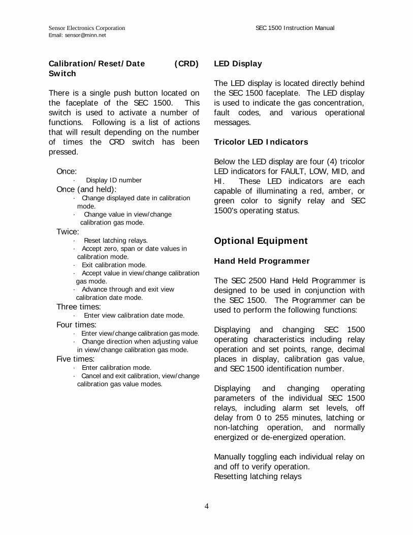
Calibration/Reset/Date (CRD) Switch There is a single push button located on the faceplate of the SEC 1500. This switch is used to activate a number of functions. Following is a list of actions that will result depending on the number of times the CRD switch has been pressed. Once: · Display ID number Once (and held):
· Change displayed date in calibration mode.
· Change value in view/change calibration gas mode. Twice: · Reset latching relays.
· Accept zero, span or date values in calibration mode.
· Exit calibration mode. · Accept value in view/change calibration gas mode. · Advance through and exit view calibration date mode. Three times: · Enter view calibration date mode. Four times: · Enter view/change calibration gas mode.
· Change direction when adjusting value in view/change calibration gas mode.
Five times: · Enter calibration mode.
· Cancel and exit calibration, view/change calibration gas value modes.
LED Display The LED display is located directly behind the SEC 1500 faceplate. The LED display is used to indicate the gas concentration, fault codes, and various operational messages. Tricolor LED Indicators Below the LED display are four (4) tricolor LED indicators for FAULT, LOW, MID, and HI. These LED indicators are each capable of illuminating a red, amber, or green color to signify relay and SEC 1500's operating status. Optional Equipment Hand Held Programmer The SEC 2500 Hand Held Programmer is designed to be used in conjunction with the SEC 1500. The Programmer can be used to perform the following functions: Displaying and changing SEC 1500 operating characteristics including relay operation and set points, range, decimal places in display, calibration gas value, and SEC 1500 identification number. Displaying and changing operating parameters of the individual SEC 1500 relays, including alarm set levels, off delay from 0 to 255 minutes, latching or non-latching operation, and normally energized or de-energized operation. Manually toggling each individual relay on and off to verify operation. Resetting latching relays

Sensor Electronics Corporation SEC 1500 Instruction Manual Email: [email protected]
5
Performing a lamp test to verify operation of all visual indicators and view the SEC 1500 identification number. Displaying a sensor synopsis which includes SEC 1500 identification number; fault code status; gas type; current gas level; range; calibration gas value; date of last calibration; active relays, if any; logic voltage, line voltage; and current analog output level. The Programmer communicates with the SEC 1500 one of two ways: RS-485 Wired Connection: A data communications cable is plugged into the Programmer and hard-wired to the Data A and Data B of the RS-485 data highway. The Programmer can then communicate individually with any SEC 1500 installed on that particular RS-485 network. Direct-Wired Connection: A data communications cable is plugged into the Programmer and a connector on the other end is plugged into a SIP connector located on the SEC 1500 processor module. The Programmer can only communicate directly with that individual SEC 1500. For more detailed operation of the Hand Held Programmer, refer to the Instruction Manual for this unit.
IV. OPERATION Installation and Startup The first step in the installation process is to establish a mounting location for the SEC 1500. Select a location that is typical of the atmosphere to be monitored or close to the anticipated source of a dangerous gas. The SEC 1500 should be solidly attached at the mounting location with the sensor pointed down, using bolts through the mounting flanges on the enclosure. Next, field wiring must be brought to the SEC 1500. For DC units use of shielded cable is highly recommended to prevent electrical interference from affecting the operation of the SEC 1500. The wiring must be installed in accordance with all applicable local electrical codes. Power First determine what the input power requirements are for the unit being installed. The enclosure drawing will indicate where to terminate the appropriate wires. Place the stripped end of the wire into the side of the terminal block and securely tightening the screw on top. If shielded wire has been used, connect the shield wire to the power supply earth ground. The supply wires must be sized so that they are able to supply the specified voltage to the SEC 1500 at the rated current.
Sensor Electronics Corporation SEC 1500 Instruction Manual Email: [email protected]
6
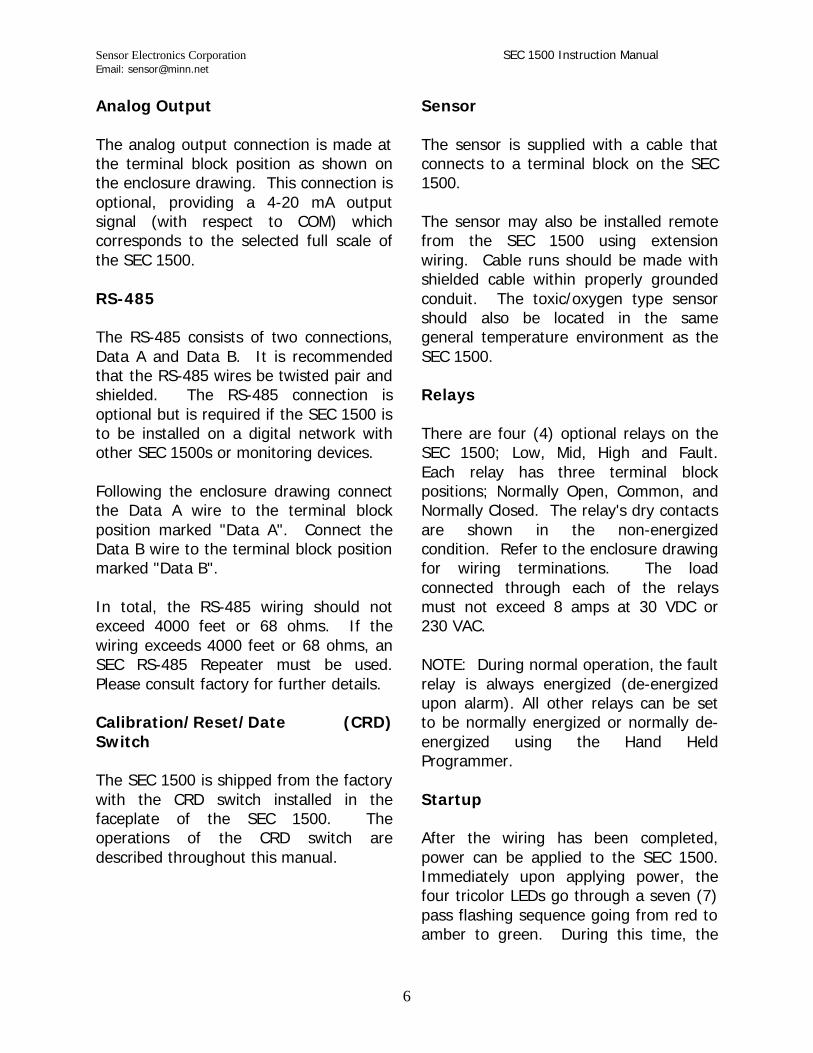
Analog Output The analog output connection is made at the terminal block position as shown on the enclosure drawing. This connection is optional, providing a 4-20 mA output signal (with respect to COM) which corresponds to the selected full scale of the SEC 1500. RS-485 The RS-485 consists of two connections, Data A and Data B. It is recommended that the RS-485 wires be twisted pair and shielded. The RS-485 connection is optional but is required if the SEC 1500 is to be installed on a digital network with other SEC 1500s or monitoring devices. Following the enclosure drawing connect the Data A wire to the terminal block position marked "Data A". Connect the Data B wire to the terminal block position marked "Data B". In total, the RS-485 wiring should not exceed 4000 feet or 68 ohms. If the wiring exceeds 4000 feet or 68 ohms, an SEC RS-485 Repeater must be used. Please consult factory for further details. Calibration/Reset/Date (CRD) Switch The SEC 1500 is shipped from the factory with the CRD switch installed in the faceplate of the SEC 1500. The operations of the CRD switch are described throughout this manual.
Sensor The sensor is supplied with a cable that connects to a terminal block on the SEC 1500. The sensor may also be installed remote from the SEC 1500 using extension wiring. Cable runs should be made with shielded cable within properly grounded conduit. The toxic/oxygen type sensor should also be located in the same general temperature environment as the SEC 1500. Relays There are four (4) optional relays on the SEC 1500; Low, Mid, High and Fault. Each relay has three terminal block positions; Normally Open, Common, and Normally Closed. The relay's dry contacts are shown in the non-energized condition. Refer to the enclosure drawing for wiring terminations. The load connected through each of the relays must not exceed 8 amps at 30 VDC or 230 VAC. NOTE: During normal operation, the fault relay is always energized (de-energized upon alarm). All other relays can be set to be normally energized or normally de-energized using the Hand Held Programmer. Startup After the wiring has been completed, power can be applied to the SEC 1500. Immediately upon applying power, the four tricolor LEDs go through a seven (7) pass flashing sequence going from red to amber to green. During this time, the

Sensor Electronics Corporation SEC 1500 Instruction Manual Email: [email protected]
7
LED display will indicate the assigned SEC 1500 identification number. After this initial startup sequence is complete, all four (4) tricolor LEDs will go solid green and the LED display will indicate the gas concentration. For one minute after power up, the relays will be inactive. Typically, after being powered up, the SEC 1500 display reading will go upscale and then gradually fall as the gas sensor stabilizes. This is normal and the relays are inactive during this time to eliminate unwanted alarm actions. During the one minute period, the analog output will remain at 4 mA, regardless of the display reading. If more than one SEC 1500 is being installed on an RS-485 network, they must each be assigned a unique identification number. If identification numbers have not been assigned at the factory, the default number for each is 9999. In this case, each SEC 1500 must be powered on one at a time, and have new identification numbers assigned to them using the Hand Held Programmer. If desired, the configuration and programming information contained in each individual SEC 1500 may be checked and changed if necessary using the SEC 2500 Hand Held Programmer. Monitoring After the one minute warm up period, the SEC 1500 is ready for operation. The LED display continually indicates the current concentration of gas specific to the particular SEC 1500. If connected to
a monitoring device on an RS-485 network, the SEC 1500 will report its status and programming information upon being polled. The SEC 1500 also generates a 4-20 mA signal, on a continuous basis, representative of the display reading. For a toxic gas version SEC 1500, the concentration of gas is generally displayed in parts per million (PPM). For an oxygen version SEC 1500, the concentration is displayed as a percentage by volume content in the air being monitored. Oxygen concentration in a normal air environment is 20.9%. If the concentration of oxygen falls below a normal value, a potentially dangerous situation exists due to oxygen deficiency. If the concentration of oxygen rises above a normal value, an explosion hazard may exist. Alarms The most important function of the SEC 1500 is to activate alarms when gas concentrations approach dangerous levels. There are three (3) levels of alarm for gas concentration on the SEC 1500; Low, Mid, and High. They are independently adjustable using the Hand Held Programmer. All alarms activate on rising gas concentrations except for the Low and Mid oxygen alarm which both activate on a falling concentrations. When gas concentration exceeds the Low alarm set point (or falls below the setpoint in the case of oxygen) the low alarm relay will activate and the low alarm LED will turn red. When gas concentration exceeds

Sensor Electronics Corporation SEC 1500 Instruction Manual Email: [email protected]
8
the mid alarm set point (or falls below the set point in the case of oxygen) the mid alarm relay will also activate and the mid alarm LED will turn red. When gas concentration exceeds the high alarm setpoint, the high alarm relay will activate and the high alarm LED will turn red. If a fault condition exists, the fault alarm relay will activate and the tricolor LED will turn red. The fault code will be displayed by the SEC 1500 alternating with the gas concentration. During all alarm conditions, the analog output value will fall to 0 mA. Normally Energized/De-energized The action of the gas alarms can be independently set to normally energized or normally de-energized using the Programmer. Normal condition is defined as power applied to the SEC 1500 with no gas alarms in effect. NOTE: The fault alarm is normally energized, and is de-energized in alarm conditions. Latching/Non-latching The action of all relays can be independently set to latching or non-latching using the Programmer. If an alarm is non-latching, the corresponding relay and tricolor LED will deactivate (reset) when the alarm condition has passed. If an alarm has been set to be latching, the corresponding relay and tricolor LED will remain active after the alarm condition has passed. In the case of a fault alarm, the fault code will remain displayed by the SEC 1500, alternating with the gas concentration. The relay,
LED and fault code can then be deactivated (reset) by pressing the CRD switch two (2) times. In the case of the latching low alarm only, the low alarm relay can be acknowledged when the low alarm condition still exists. This is true only if the gas concentration is below the mid alarm set level. After the low alarm relay has been acknowledged and during the time that the low alarm condition exists, the low alarm tricolor LED will flash amber. Off Delay All non-latching gas alarms can be configured to have an off delay timer. If an off delay has been set, the alarm relay and tricolor LED will remain active after the alarm condition has passed for the period of time specified as the off delay. After this period of time, the alarm relay and tricolor LED will automatically deactivate (reset). The off delay for each alarm can be independently set, using the Programmer, to any value within the range of 0-255 minutes. During the time that the off delay is in effect, the alarm relay and tricolor LED can not be reset using the Programmer or CRD switch. This feature applies to non-latching alarms only. View Last Calibration Date The date of last calibration on any SEC 1500 can be viewed using the CRD switch with the following procedure: Press the CRD switch three (3) times. Consecutive push-button actions must be no more than one second apart.

Sensor Electronics Corporation SEC 1500 Instruction Manual Email: [email protected]
9
The SEC 1500 will initially display: dATE It will then flash YEAr, alternating with the year the detector was last calibrated. Example: YEAr and 01 While in the calibration date mode, all four (4) tricolor LED indicators will flash green, the analog output will drop to 1.5 mA, and the relays will be inactive. NOTE: The calibration date mode may be exited at any time by pressing the CRD switch five times. This will cause the SEC 1500 to momentarily display CnCl, and then return to the normal monitoring display. Press the CRD switch two times to advance. The SEC 1500 display will now flash mnTH, alternating with the month (1-12) the detector was last calibrated: Example: mnTH and 11 Press the CRD switch two times to advance. The SEC 1500 display will now flash dAY, alternating with the day (1-31) the detector was last calibrated. Example: dAY and 29 Press the CRD switch two times to advance. The SEC 1500 display will now flash: donE Press the CRD switch two times to exit the calibration date mode and return to the normal monitoring display. The four
(4) tricolor LEDs will go solid green and the display will indicate the current gas concentration. NOTE: While in the View Calibration Date mode, the SEC 1500 will time out to the normal operating mode after five (5) minutes if the magnetic switch remains inactive. View/Change Calibration Value The value of calibration gas programmed into the SEC 1500 memory can be viewed or changed using the CRD switch. This programmed value must equal the actual value used when the detector is calibrated. Use the following procedure to view/change calibration gas value: Press the CRD switch four times. The SEC 1500 will alternately display: CAL gAS XX (XX = Value of Calibration Gas programmed into SEC 1500 memory) XXX (XXX = Gas unit programmed into SEC 1500 memory) Example: CAL gAS 100 PPM The SEC 1500 will then flash gAS alternating with the value of calibration gas currently entered into the detector's memory. While in the calibration gas mode, all four (4) tricolor LED indicators

Sensor Electronics Corporation SEC 1500 Instruction Manual Email: [email protected]
10
will flash green, the analog output will drop to 1.5 mA, and the relays will be inactive. The operator can now either exit the calibration gas mode or change the value of calibration gas displayed. NOTE: The calibration gas value should only be changed immediately prior to a calibration, as it will instantaneously affect the way the SEC 1500 interprets the sensor input. To exit the calibration gas mode, press the CRD switch two times. The SEC 1500 will momentarily display donE, and return to the normal monitoring display. The four (4) tricolor LEDs will go solid green and the display will indicate the current gas concentration. To change the calibration gas value programmed into the SEC 1500 memory, press and HOLD the CRD switch. The displayed calibration gas value will begin to ascend (example: 51, 52, 53 ...). To change the direction that the display is counting (i.e., descend) press the CRD switch four times. Now when the CRD switch is pressed and held, the displayed calibration gas value will count down (i.e., 53, 52,...). When the desired calibration gas value is displayed, release the CRD switch. With the correct value displayed, press the CRD switch two times to lock in this number. The SEC 1500 will momentarily display donE, and return to the normal monitoring display. The four (4) tricolor
LEDs will go solid green and the display will indicate the current gas concentration. Note that while in the View/Change Calibration Gas mode, the SEC 1500 will automatically time out to the normal operating mode after fifteen (15) minutes if the CRD switch remains inactive. V. CALIBRATION Sensor Calibration and Setting Calibration Date The SEC 1500 must be calibrated regularly using known gas samples, representative of the gas being detected. Calibration consists of exposing the SEC 1500 sensor to the known gas sample and adjusting the electronic circuitry to generate a reading equal to the concentration of the calibration gas. The SEC 1500, eliminating the need for any special tools, does this adjustment electronically. For maximum accuracy, the concentration of the calibration gas should be a significant percentage of the measuring range. Prepared gas mixtures in pressurized disposable cylinders, calibration accessories, and calibration kits are available from Sensor Electronics Corporation. The frequency of calibration is dependent upon how often the instrument is used and in what type of environment it is being used. A good indication of how often the SEC 1500 should be calibrated is the amount of adjustment required when a calibration is performed. If the

Sensor Electronics Corporation SEC 1500 Instruction Manual Email: [email protected]
11
SEC 1500 must consistently be adjusted a significant amount, the calibration interval should probably be more frequent. The SEC 1500 may be calibrated using the CRD switch or the SEC 2500 Hand Held Programmer. The following procedure describes the calibration of the SEC 1500 using the CRD switch: 1. If the SEC 1500 has just been powered up, allow the sensor to stabilize for at least sixty (60) minutes. 2. Connect an adjustable valve to a cylinder of calibration gas, suitable for calibrating in the SEC 1500 measuring range. NOTE: The calibration gas value programmed into SEC 1500 memory must be the same as the actual calibration gas used. 3. Using flexible tubing, connect the cylinder's valve, through a 0-2 SCFH (0-1 LPM) flow meter to a calibration adapter. 4. Press the CRD switch five times. The SEC 1500 will alternately display: CAL gAS XX (XX = Value of calibration gas programmed into SEC 1500 memory) XXX (XXX = Gas unit programmed into SEC 1500 memory) Example: CAL gAS 50 PPM
While in the calibration mode, all four (4) tricolor LED indicators will flash green, the analog output will drop to 1.5 mA, and the relays will be inactive. NOTE: If the calibration gas value displayed by the SEC 1500 during this step is not the same as the calibration gas being used, it must be changed. NOTE: To increase the accuracy of the calibration process, it is recommended that the holes on the sensor housing be covered while applying the span and zero gas. 5. The SEC 1500 will then display ACAL and begins to function as a voltmeter, displaying the analog signal from the sensor. For complete details on how to perform an analog calibration refer to the Sensor Maintenance section of this manual. To proceed with a standard calibration push the CRD switch twice. 6. The SEC 1500 will then flash ZErO, alternating with the current gas concentration. 7. With the SEC 1500 sensor in a known gas-free environment, press the CRD switch two times to lock in the zero gas value. NOTE: If the atmosphere surrounding the SEC 1500 sensor is uncertain, apply zero air to the sensor using the calibration adapter. NOTE: For an Oxygen version SEC 1500, this step must be performed with an oxygen-free inert gas such as nitrogen.
Sensor Electronics Corporation SEC 1500 Instruction Manual Email: [email protected]
12
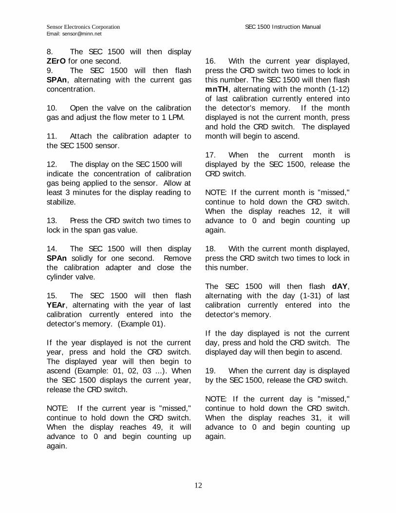
8. The SEC 1500 will then display ZErO for one second. 9. The SEC 1500 will then flash SPAn, alternating with the current gas concentration. 10. Open the valve on the calibration gas and adjust the flow meter to 1 LPM. 11. Attach the calibration adapter to the SEC 1500 sensor. 12. The display on the SEC 1500 will indicate the concentration of calibration gas being applied to the sensor. Allow at least 3 minutes for the display reading to stabilize. 13. Press the CRD switch two times to lock in the span gas value. 14. The SEC 1500 will then display SPAn solidly for one second. Remove the calibration adapter and close the cylinder valve. 15. The SEC 1500 will then flash YEAr, alternating with the year of last calibration currently entered into the detector's memory. (Example 01). If the year displayed is not the current year, press and hold the CRD switch. The displayed year will then begin to ascend (Example: 01, 02, 03 ...). When the SEC 1500 displays the current year, release the CRD switch. NOTE: If the current year is "missed," continue to hold down the CRD switch. When the display reaches 49, it will advance to 0 and begin counting up again.
16. With the current year displayed, press the CRD switch two times to lock in this number. The SEC 1500 will then flash mnTH, alternating with the month (1-12) of last calibration currently entered into the detector's memory. If the month displayed is not the current month, press and hold the CRD switch. The displayed month will begin to ascend. 17. When the current month is displayed by the SEC 1500, release the CRD switch. NOTE: If the current month is "missed," continue to hold down the CRD switch. When the display reaches 12, it will advance to 0 and begin counting up again. 18. With the current month displayed, press the CRD switch two times to lock in this number. The SEC 1500 will then flash dAY, alternating with the day (1-31) of last calibration currently entered into the detector's memory. If the day displayed is not the current day, press and hold the CRD switch. The displayed day will then begin to ascend. 19. When the current day is displayed by the SEC 1500, release the CRD switch. NOTE: If the current day is "missed," continue to hold down the CRD switch. When the display reaches 31, it will advance to 0 and begin counting up again.

Sensor Electronics Corporation SEC 1500 Instruction Manual Email: [email protected]
13
20. With the current day displayed, press the CRD switch two times to lock in this number. The SEC 1500 will then flash donE. 21. To end the calibration sequence, press the CRD switch two times. The display will indicate donE solidly for one second and then return to its basic monitoring mode. The four tricolor LEDs will go solid green and the display will indicate the current gas concentration. NOTE: At any point during the calibration sequence, if the SEC 1500 is left unattended for more than 15 minutes, it will automatically return to the normal operating mode. VI. MAINTENANCE General General maintenance of the SEC 1500 consists primarily of periodic checks to be sure that the display remains at zero (20.9 for oxygen) and that it is responsive to gas. The four (4) tricolor LEDs beneath the SEC 1500 display should also be checked periodically to verify that the instrument is in a normal operating condition (all LEDs solid green). If the SEC 1500 on-board relays are used to control any auxiliary equipment, they can be tested using the manual relay control function of the Programmer.
Fault Codes In the event of an operating fault, the SEC 1500 will generate an alarm. The fault relay will become de-energized and the power LED will go red, the SEC 1500 display will indicate a fault code number alternating with current gas concentration. The analog output will fall to 0 mA.
Fault Code Description FL 10 Sensor is bad FL 11 Insufficient gain FL 12 Analog signal out of range FL 13 Zero drift FL 14 Excessive gain FL 21 Logic voltage out of tolerance CNFg Incomplete configuration in EEPROM
Table 6.1-SEC 1500 Fault Codes The following are probable causes and possible remedies for the faults listed in Table 6.1. FL 10 - Sensor is bad This fault code is generated immediately following a calibration when the sensitivity of the sensor has fallen below a pre-determined limit. When this fault code is displayed, a new sensor must be installed before normal operation of the SEC 1500 can resume. FL 11 - Insufficient gain This fault code is also generated immediately following a calibration when the sensitivity of the sensor has fallen below a pre-determined limit.

Sensor Electronics Corporation SEC 1500 Instruction Manual Email: [email protected]
14
FL 12 - Analog signal out of range This fault code is generated when the analog output from the sensor circuitry has drifted out of the measuring range of the analog to digital (A/D) converter. FL 13 - Zero drift This fault code is generated when the output from the sensor below the zero point, set during last calibration, by more than 5%. To correct this fault condition, the SEC 1500 must be calibrated. FL 14 - Excessive gain This fault code is generated when the diagnostic software of the SEC 1500 has determined that the sensitivity of the sensor circuitry is too high, making it impossible to measure 115% of full scale within the range of the A/D converter. FL 21 - Logic voltage out of tolerance This fault code is generated when the voltage powering the logic circuitry of the SEC 1500 falls below or rises above its nominal value of 5 volts by more than 5%. CnFg - Incomplete configuration in EEPROM This message is generated when there is not enough information programmed into the SEC 1500 memory. This condition generally occurs only when an unconfigured SEC 1500 is powered up for the first time or when a blank EEPROM has been installed. To correct this condition, all configuration parameters
must be entered into the SEC 1500 memory using the Hand Held Programmer. Sensor Maintenance All of the sensors used with the SEC 1500 are non-serviceable and must be replaced when they lose their sensitivity. This loss in sensitivity is signaled by a Fault Code 10 or 14 generated immediately after a calibration is performed.

Sensor Electronics Corporation SEC 1500 Instruction Manual Email: [email protected]
15
Changing Sensors 1. Disconnect power from the SEC 1500. Remove the four screws holding the sensor housing in place, and remove the sensor housing. 2. Remove the four screws holding the sensor board to the standoffs. Disconnect the sensor wiring from the connector on the SEC 1500 and loosen the connector sealing the wire to the housing. The sensor board can now be removed. 3. Run the wiring from the new sensor board through the sealing connector and terminate the wires on the terminals on the SEC 1500. The sensor board can now be attached to the standoffs. 4. Re-attach the sensor housing. The new sensor is now ready operation. The sensor is pre-calibrated at the factory, but it is recommended that an analog adjustment be performed prior to putting the SEC 1500 back in operation. Analog Calibration 1. If the SEC 1500 has just been powered up, allow the sensor to stabilize. 2. Connect an adjustable valve to a cylinder of calibration gas, suitable for calibrating in the SEC 1500 measuring range. Record the actual gas concentration on the calibration form. NOTE: The calibration gas value programmed into SEC 1500 memory must be the same as the actual calibration gas used.
3. Using flexible tubing, connect the cylinder's valve, through a 0-2 SCFH (0-1 LPM) flow meter to a calibration adapter. 4. Press the CRD switch five times. The SEC 1500 will alternately display: CAL gAS XX (XX = Value of calibration gas programmed into SEC 1500 memory) XXX (XXX = Gas unit programmed into SEC 1500 memory) Example: CAL gAS 50 PPM While in the calibration mode, all four (4) tricolor LED indicators will flash green, the analog output will drop to 1.5 mA, and the relays will be inactive. NOTE: If the calibration gas value displayed by the SEC 1500 during this step is not the same as the calibration gas being used, it must be changed. 5. The SEC 1500 will then display ACAL and begin to function as a voltmeter, displaying the analog signal from the sensor. 6. In a clean air environment the display will read 0.25. If the display is not reading 0.25 and the sensor is in a clean air environment, the reading should be adjusted. 7. On the side of the sensor housing there are two small holes. Behind each hole is an adjustment control, one for

Sensor Electronics Corporation SEC 1500 Instruction Manual Email: [email protected]
16
zero and one for span. These controls and accessed by means of a small flat blade screwdriver. 8. To adjust the zero insert a small screwdriver into the hole labeled ZERO. Adjust the display to read 0.25. 9. To adjust the SPAN, calibration gas must be applied. Open the valve on the calibration gas and adjust the flow to 1 LPM, and attach the calibration adapter to the SEC 1500. 10. Allow the reading on the display to stabilize. The correct reading will depend on the calibration gas used and the pre-programmed range. To determine the correct reading use the following formula. Voltage = (Cal Gas Value x 1.625) Range Value Example: For a SEC 1500 CO, with a range of 200 PPM and a calibration gas of 100 PPM; Voltage = (100 x 1.625) 200 Voltage = 1.06 11. With the gas applied adjust the display to read the correct voltage. 12. After setting the voltage with gas applied, remove the gas and observe the voltage on the display decrease and stabilize. 13. Once the display has returned to 0.25 the analog calibration routine may be exited. Press the CRD switch five (5) times and the SEC 1500 will return to normal operation.
NOTE: If a fault code exists after an analog calibration, it may be necessary to calibrate the SEC 1500 with the CRD switch to clear the fault.
+ 0.25
+ 0.25

Sensor Electronics Corporation SEC 1500 Instruction Manual Email: [email protected]
17
VII. WARRANTY Sensor Electronics Corporation (SEC) warrants products manufactured by SEC to be free from defects in workmanship and materials for a period of two (2) years from date of shipment from the factory. Any parts returned freight pre-paid to the factory and found defective within the warranty would be repaired or replaced, at SEC's option. SEC will return repaired or replaced equipment pre-paid lowest cost freight. This warranty does not apply to items that by their nature are subject to deterioration or consumption in normal service. Such items may include: Fuses and Batteries. Catalytic, Toxic and Oxygen sensors that may be covered by a standard warranty based on the specific application. (Consult Factory) Warranty is voided by abuse including rough handling, mechanical damage, alteration or repair. This warranty covers the full extent of SEC liability and SEC is not responsible for removal, replacement costs, local repair costs, transportation costs or contingent expenses incurred without prior written approval. Sensor Electronics Corporation's obligation under this warranty shall be limited to repair or replacement of any product that has been returned to Sensor Electronics Corporation for warranty consideration. This warranty is expressly in lieu of any and all other warranties expressed or implied, and all other obligations or liabilities on the part of Sensor Electronics Corporation including but not limited to, the fitness for a particular purpose. In no event shall Sensor Electronics Corporation be liable for direct, incidental, or consequential loss or damage of any kind connected with the use of its products or failure to function or operate properly. Year 2000 Compliance All Sensor Electronics products have been tested and are certified by Sensor Electronics to accurately process date/time and date/time related data from, into and between the 20th and 21st centuries. Sensor Electronics products neither contain nor create any logical or mathematical inconsistency, will not malfunction, and will not cease to function when processing date/time data.
Sensor Electronics Corporation SEC 1500 Instruction Manual Email: [email protected]
18
Sensor Electronics Corporation5500 Lincoln Drive
Minneapolis, MN 55436Tel: (612) 938-9486Fax: (612) 938-9617
e-mail: [email protected]
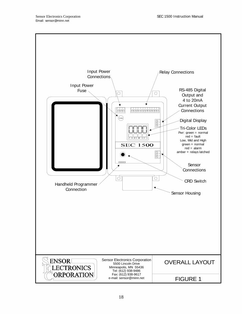
OVERALL LAYOUT
FIGURE 1
P W RL O WM I D H I
FUSE
Relay ConnectionsInput PowerConnections
RS-485 DigitalOutput and 4 to 20mA
Current OutputConnections
Sensor Connections
Digital Display
Input PowerFuse
Handheld ProgrammerConnection
Sensor Housing
CRD Switch
Tri-Color LEDsPwr: green = normal
red = faultLow, Mid and Highgreen = normal
red = alarmamber = relays latched

Sensor Electronics Corporation SEC 1500 Instruction Manual Email: [email protected]
19
P W RL O WM I D H I
FUSE
4“
6.2“
8.2“
8.9“
10“
6.5“
6.0“
DIMENSIONAL
1.75“
Sensor Electronics Corporation5500 Lincoln Drive
Minneapolis, MN 55436Tel: (612) 938-9486Fax: (612) 938-9617
e-mail: [email protected] FIGURE 2

Sensor Electronics Corporation SEC 1500 Instruction Manual Email: [email protected]
20
SENSOR HOUSING
SPANZER
O
4.5“
4.0“
3.5“
2“ 2.5“
SENSOR SEPERATIONPLATE
Ambient AirDiffusion Holes Calibration Port Analog Adjustment
Access Holes
4.5“
SENSOR HOUSINGAND SEPARATION PLATE
1.75“
Sensor Electronics Corporation5500 Lincoln Drive
Minneapolis, MN 55436Tel: (612) 938-9486Fax: (612) 938-9617
e-mail: [email protected] FIGURE 3

Sensor Electronics Corporation SEC 1500 Instruction Manual Email: [email protected]
21
PWR LOW MID HI
FUSE
LOW MID HIGH FLT DATA BDATA ACOMMON4-20MA
REDWHITEBLACK
SensorConnections
RELAY CONNECTIONS
For 120 VAC units = Line For 24 VDC units = Positive
For 120 VAC units = NeutralFor 24 VDC units = Negative
The RS-485 DigitalOutput Connections
The 4 to 20mAOutput Connections
WIRING CONNECTIONDETAILS
Sensor Electronics Corporation5500 Lincoln Drive
Minneapolis, MN 55436Tel: (612) 938-9486Fax: (612) 938-9617
e-mail: [email protected] FIGURE 4

Sensor Electronics Corporation SEC 1500 Instruction Manual Email: [email protected]
22
NEMA 4X Fiberglass Windowed Electronic Enclosure (Steel Sensor Housing)
Model Number Description SEC 1500-4211XXX 24 VDC; No Relays SEC 1500-4212XXX 24 VDC; With Relays SEC 1500-4221XXX 120 VAC; No Relays SEC 1500-4222XXX 120 VAC; With Relays
NEMA 4X Fiberglass Windowed Electronic Enclosure (Stainless Steel Sensor Housing)
Model Number Description SEC 1500-4111XXX 24 VDC; No Relays SEC 1500-4112XXX 24 VDC; With Relays SEC 1500-4121XXX 120 VAC; No Relays SEC 1500-4122XXX 120 VAC; With Relays
NEMA 4X Fiberglass Windowless Electronic Enclosure (Steel Sensor Housing)
Model Number Description SEC 1500-3211XXX 24 VDC; No Relays SEC 1500-3212XXX 24 VDC; With Relays SEC 1500-3221XXX 120 VAC; No Relays SEC 1500-3222XXX 120 VAC; With Relays
NEMA 4X Fiberglass Windowless Electronic Enclosure (Stainless Steel Sensor)
Model Number Description SEC 1500-3111XXX 24 VDC; No Relays SEC 1500-3112XXX 24 VDC; With Relays SEC 1500-3121XXX 120 VAC; No Relays SEC 1500-3122XXX 120 VAC; With Relays
NEMA 4X Stainless Steel Electronic Enclosure (Stainless Steel Sensor Housing) Model Number Description SEC 1500-5111XXX 24 VDC; No Relays SEC 1500-5112XXX 24 VDC; With Relays SEC 1500-5121XXX 120 VAC; No Relays SEC 1500-5122XXX 120 VAC; With Relays
XXX denotes remote sensor option and gas type.
X = Remote Mounting Plate Option 0 = No remote mounting plate 1 = Aluminum remote mounting plate 2 = Stainless steel remote mounting plate XX = Gas Type 10 Bromine 16 Carbon Monoxide 23 Hydrogen Fluoride 29 Diborane 11 Chlorine 18 Hydrogen 24 Hydrogen Sulfide 30 Germane 12 Chlorine Dioxide 19 Oxygen 25 Nitric Oxide 31 Hydrogen 13 Fluorine 20 Phosgene 26 Nitrogen Dioxide Selenide 14 Ozone 21 Hydrogen Chloride 27 Sulfur Dioxide 32 Phosphine 15 Ammonia 22 Hydrogen Cyanide 28 Arsine 33 Silane

Sensor Electronics Corporation SEC 1500 Instruction Manual Email: [email protected]
23
Part Number Description
15009500 Replacement Control Board (24 VDC, No Relays) 15009501 Replacement Control Board (24 VDC, With Relays) 15009502 Replacement Control Board (120 VAC, No Relays) 15009503 Replacement Control Board (120 VAC, With Relays) 15009504 Replacement Control Board (220 VAC, No Relays) 15009505 Replacement Control Board (220 VAC, With Relays) 1500-91XX-XXXXX Replacement SEC 1500 Sensor Board
Part Number Description
172-0175C SEC 2500 Hand Held Programmer 147-1000C SEC 2500 Hand Held Programmer Cable 15001008 SEC 1500 Weather Guard 15001010 SEC 1500 Calibration Adaptor 15009600 SEC 1500 Sensor Separation Plate (Aluminum) 15009601 SEC 1500 Sensor Separation Plate (Stainless Steel)
1500 – 91 XX XXXX X Range Unit of Measurement M = PPM V = % VOL B = PPB
Gas Type (Listed on previous page)