Small Quantity Emission Rates and De Minimis Emission ... - Wa

Techniques in microscopy
• Conventional (light) microscopybright & dark field, phase & interference contrast
• Fluorescence microscopylight sources, fluorescence detectors, digital image, objectives
• Single- & two-photon confocal microscopybasic idea & differences, advantages & disadvantages
• What is the optimal technique (for my question)?

Conventional (light) microscopy
(http://micro.magnet.fsu.edu)

Light microscope: general structure I
Magnification
Illumination
Specimen
(with modification http://micro.magnet.fsu.edu)

objective
specimen
Light microscope: general structure II
ocular
f
F
2f
object
imaginaryimage
(magnifying glass)
f
F
2f
objectreal
imagecondensor
light sourceIllum
inat
ion
Mag
nific
atio
n

Final (imaginary) image
ocular (magnifying glass)
A light microscope is a combinationof a slide projector with a magnifying glass
Total magnification = Mobjective x Mocular
light
Intermediate (real) image(on the projector screen)
objective (slide projector)

bright field with specimen
specimenobject plane
objective
condensor
Bright and dark field illumination

dark field without specimen
object plane
objective
condensor
Bright and dark field illumination
- ring diaphragm (usually)- dark field condensor
specimen
dark field with specimen

Bright and dark field illumination
Bright field• total illumination of the specimen• direct light collection by objective• dark/colored object on bright background
Objects with a sharprise in refraction index
Dark field• part-illumination of the specimen• scattered light collected by objective• bright object on dark background
Objects with high contrast
(with modification http://mikroskopie.de)

Microscopy illumination after Köhler(or the mystery condensor adjustment)
A. Köhler(1866-1948) retina
intermediateimage plane
focusedspecimen
fielddiaphragm
conjugate planesin the image path
ocular
objective
condensor
aperturediaphragm
light source
optical elements
(eye)
specimen
condensor
objective
diaphragm

1.Light source on
2.Open up fully field diaphragmand aperture diaphragm
3.Choose prefered objective(at least 10x), focus specimen
How to do adjust the Köhler illumination
4.Close down field diaphragm;focus the image of the fielddiaphragm sharply onto thealready focused specimen
5.If neccessary center the condensor;then open the field diaphragmuntil it just disappears from view
6.Take out one of the eyepieces,look down the tube andadjust the aperture diaphragm
Diaphragm should be 2/3 to 3/4 open(compromise between resolution & contrast)

Amplitude and phase objects influence light waves:Basic principle for phase & interference contrast
Reduction in amplitude is equalwith a reduction in light intensity(used in bright field microscopy!)
amplitude object
ampl
itude
ampl
itude
phase object
phaseSlow down of light wavepassing the phase object

Phase contrast
focussed specimen
condensorand
light source phase diaphragm
intermediate image plane
objective
phase ring
scattered lightslowed down,unscattered light

Differential interference contrast (DIC)
Specimen(inhomogen phase object)
Phasedifference
Polarisator
linearpolarized
light
Prisma(Nomarski)
two verticalpolarized
waves
Analysator
DIC prisma(Nomarski)
linear polarizedlight
(analysator verticalvs. polarisator)
unpolarizedlight

Phase contrast vs. DIC
Kidney tissue(tubule with some cells> 100 µm thick section)
Phase contrast
Buccal epithelial cell(monolayer)
DIC
(with modification http://mikroskopie.de)

Light microscopy: illumination & contrast techniques
• IlluminationTry to optimise your illumination (condensor adjustment after Köhler)
Bright field illumination: standard technique for most specimen
Dark field illumination: specific technique for monolayer specimenwith distinct differences in the refraction index
• Contrast
Phase contrast: standard technique for low-contrast monolayer specimen
DIC: standard technique for low-contrast specimen,in particularily for thick (non-monolayer) preparations
Check and improve all contrast techniques available at your microscope

Fluorescence microscopy

Basic idea of fluorescence microscopy: Stokes shift
E1
E2
E0
excitation level 1
excitationlevel 2
base level
E1 E2
λ1 λ2
Stokes shift
E = hνc = λν
E ~ 1 / λ

The use of the Stokes shift in fluorescence microscopy
dichroic mirror
fluorescence object/dye
excitation wavelenght λex
light source(arc lamp, laser)
(filter) emission wavelenght λem > λex
Detection system(eye, conventional camera, CCD, photo diode, PMT)

Fluorescence microscopy requires ...
• Fluorochrome (or autofluorescence)
• Light source

Light source
Arc lampsXenonMercury
UV IRLaser types
Argon 351 364 457 477 488 514Blue diode 405 440Helium-Cadmium 354 442
Krypton-Argon 488 569 647
Green Helium-Neon 543
Yellow Helium-Neon 594
Orange Helium-Neon 612
Red Helium-Neon 633
Red diode 635 650
Ti:Sapphire 720-980

Fluorescence microscopy requires ...
• Fluorochrome (or autofluorescence)
see Molecular Probes (www.probes.com)
• Light source
• Fluorescence detection

photo diode
Spartialresolution
Temporalresolution
CCD
conventionalphotography
Fluorescence detector systems ...
PMT

Fluorescence detector systems produce digital images
Analog Image Digital Sampling Pixel Quantization
- observer eye
- conventionalphotography
- CCD
- PMT (in combinationwith scan technique)
(with modification http://micro.magnet.fsu.edu)

Fluorescence detector systems produce digital imagespi
xelc
ount
s normalcontrast
0 255grey level
highcontrast
lowcontrast
0 255grey level0 255grey level
(with modification http://micro.magnet.fsu.edu)

Mainly fluorescence detector systems are color-blind!(Colors are based on a [pseudo-]color look-up table)

• (prefers) immersion objectives
Fluorescence microscopy requires ...
• Fluorochrome (or autofluorescence)
see Molecular Probes (www.probes.com)
• Light source
• Fluorescence detection

α
β
α
β
α β = α
Immersion objectives: Remember the refraction index!
sin αsin β n1
n2=n1 n2
n1 < n2
total reflection

Immersion objectives: Remember the refraction index!
Immersion objectivewith specimen
refraction index (n)air ≈ 1.00
water = 1.37oil = 1.5
glass = 1.5
Emission
ExcitationDMLight
source
medium (water or oil)
water or oil immersion objective
specimen

Conventional fluorescence microscopy
Advantage• low cost• uncomplicated handling• fast imaging technique
Disadvantage• no 3-dimentional imaging possible• low depth of light penetration• bleaching

Confocal microscopy
(Schmitz et al., 2001)

Conventional fluorescence microscope Laser scanning microscope
Basic idea of confocal microscopy I
specimen
full field illumination
full field detection
Arc lamp (Hg, Xe) + excitation filter
point scan illumination
point scan detection
laser light source

Laser: light source for confocal microscopyLaser (Light Amplification by Stimulated Emission of Radiation)= highly precise light source in direction, frequency, phase, polarisation- monochromatic = light has the same wavelength (continuous-wave lasers)
- coherent = light is oscilating in the same phase
- linear polarized = light is oscilating in the same direction
- can be focussed to a very high density power (compared to arc lamps)
Argon 457 477 488 514
Green Helium-Neon 543
Red Helium-Neon 633
ultra violet infra red
visible spectrum
Different wavelengths require different laser, for example ...

point scan illumination(fluorescence excitation)
Basic idea of confocal microscopy II
xy
z
laser
point scan detection(fluorescence emission)
x
y

pinhole
laser source
specimen
Confocal microscope: general structure
focal plane
x/y-scanning device
objective
x
yz
and dichroic mirror
filter
PMT excitationemission
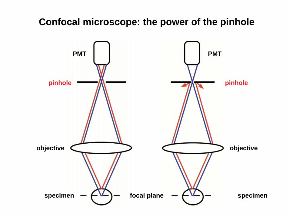
Confocal microscope: the power of the pinhole
objective
specimen
PMT
pinhole
PMT
pinhole
objective
specimen focal plane

A(x) ~ 1/I(x)
Confocal microscope: excitation profil in z-direction
focal plane

104
103
102
101
100dept
hof
ligh
tpe
netr
atio
n(µ
m)
wavelenght (µm)
visible light
IRUV
Confocal microscope: depth of light penetration

Confocal fluorescence microscopy
Advantage• improved spartial resolution• 3-dimentional scanning
Disadvantage• more complicated imaging control• low depth of light penetration• bleaching

Two-photon microscopy
A B
5 µm
100 ms

Basic idea of two-photon microscopy
single-photon excitation
hν
hν
Abs
orbt
ion
Emis
sion
two-photon excitation
hνhν*
hν*Abs
orbt
ion
Emis
sion
Two photons at the same time and at the same place with doubled wavelenght
E ~ 1 / λE = hν
c = λνE* ~ 1 / 2λE* = 1/2 E
⇒ high photon density⇒ photons from the infra red spectrum (> 750 nm)

Light source for two-photon microscopy: Ti/Sa-laser
Pump laser: solid-state cw laser, 532 nm, 5 W(Millennia, Spectra Physics)
Mode-locked Titan-Sapphire laser(Tsunami, Spectra Physics)• avarage power > 0.7 W at 800 nm• pulsewidth < 100 fs• nominal repetition rate 80 MHz• turning range 720 - 850 nm
ExcitationEmission
Titan-Sapphire spectra

Two-photon excitation
laser pulse
focal plane
the required photon density for two-photon excitationcan be established only in the focal plan and within a laser puls
photon
non-exciteddye molecule2p-exciteddye molecule
(with modification Piston, 1999)

excitationemission
x/y-scanning deviceIR laser
Single vs. two-photon microscope: general structure
and dichroic mirror
PMT
x
yz
pinhole
PMTexcitationemission

descanned detection Non descanned detection (NDD)
Fluorescence detection using 2-photon excitation
specimen
full field detection
pulsed Ti:Sa laser
point scan illumination
point scan detection
point scan illumination
pulsed Ti:Sa laser

x/y-scanning device& dichroic mirror (DM)
DM
objective
condensor
non-descanned (NDD) PMT 3 & 4
trans-non-descanned (NDD) PMT 5
DM
prisma for spectral analyse
DM
specimen
(with modification Oertner, 2002)
excitation beam
descanned PMT 1 & 2
Two-photon microscopy with descanned and NDD-PMT

A(x) ~ 1/I(x)
single-photon excitation
focal plane
A(x) ~ 1/I2(x)
two-photon excitation
Single vs. two-photon excitation: excitation profile

Two-photon microscope: depth of light penetration
104
103
102
101
100dept
hof
ligh
pene
trat
ion
(µm
)
wavelenght (µm)
visible light
IRUV

Single vs. two-photon microscopy: bleaching
(with modification Kubitscheck et al., 1996)20 µm 10 µm
two-photonabsorbtion
(760 nm; Ti:Sa)
focal plane
(3D-FITC-dextran gel; irradiated area ~ 10 x 20 µm)
x
z
y
x
single-photonabsorbtion
(488 nm; Ar)focal plane

Two-photon microscope: excitation spectra
Calcium green (506/533)
Fluo-3 (505/526)
Cascade blue (400/420)
Lucifer yellow (428/533)
1000
Excitation wavelenght (nm)
Two-
phot
oncr
oss
sect
ion
600 700 800 900
10-3
10-2
10-1
100
101
102
hνhν
hνAbs
orbt
ion
Emis
sion
Simply doubling the excitation wavelenght?
(with modification http://micro.magnet.fsu.edu)

Two-photon microscopy
Advantage• optimized z-resolution• reduced bleaching• higher efficiency (removed pinhole)• higher depth of light penetration
Disadvantage• complicate combination of laser and imaging control• cost• reduced temporal resolution

Spatialresolution
Temporalresolution
Intensity and spectral resolution(dynamic range, signal-to-noise-ratio)
„Eternal triangle of compromise“ (Shotton, 1995)
Limitations of fluorescence microscopy
light source & fluorescence dye
fluorescence detection

spatial resolution
depth of penetration
bleaching
temporal resolution
cost
available dyes
Fluorescence microscopy
conventional
0
0
0
++
two-photon
+ +
+ +
+
0
confocal(single-photon)
+
+
0
0
increasing
++
(+)+
What is the proper technique for my question?

What is the proper technique for my question?
confocal (single-photon) fluorescence imaging
- multilabling using different dyes (require of different wavelenght)
- thin preparation (< 100 µm): cell culture (monolayer), fixed preparations
two-photon fluorescence imaging
- thick preparation: acute and cultured brain slice
- in vivo imaging with interest on deeper structures
conventional fluorescence imaging
- fast and full frame imaging
- dual-wavelenght functional imaging (Fura-2, BCECF, etc.)

Spinning Disk Microscope
Advantage
-fast scanning (300 frames/s)
-low phototoxicity
Disadvantage
-fixated pinhole-no FRAP
source Duke University

TIRF Microscope
TIRF – Total InternalReflection Fluorescence
Advantage
-improved axial resolution(50-150nm)
-signal to noise ratio
Disadvantage
-very low depth of light penetration (< 150nm)
Nikon
sourceNikon

STED Microscope
Grafik: Max-Planck-Institut für biophysikalische Chemie"
STED – Stimulated Emission Depletion
Advantage
-improved lateral resolution (50-70nm) as compared with a fluorescence- or confocalmicroscope
Disadvantage
-cost-bleaching

PALM Microscope
PALM – Photoactivated LocalizationMicroscopy
Advantage
-high lateral resolution (≥ 20nm)
-multi – channel recording
Disadvantage
-cost
-higher background fluorescence than STED
source Science 2006

Notes on confocal resolution
Lateral resolution
FWHM = 0.4 * λ / NA
Axial resolution
FWHM = 0.45 * λ / n (1-cosα)
NA = n*sinα
FWHM:full width half maximum (or spatial resolution)
NA:numeral aperture of the chosen objective
n:refraction index of the sample medium (for air: n = 1, for immersion oil: n = 1.5)
λ:laser wavelength

Notes on confocal resolution
The improvement in spatial resolution corresponds lateral to 1.4x and axial to 6x compaired with the conventional fluorescence microscopy. You can adjust the spatial resolution in the LCS software using “Zoom” and “Format”.
As a simple rule you can use:
Lateral: resolution/3 = optimal size of the voxelAxial: resolution/3 = optimal choice of the z-scan
Please note: the spatial resolution depends on the used wavelength.