Seatime Report - LLMN M/T Tradewind Force
34
Seatime Report - LLMN Miquel Solé Rebull 1 M/T Tradewind Force IMO Number : 9127710 Operation and Dry Docking 2012 Facultat Nàutica de Barcelona Degree: Llicenciatura en Màquines Navals Course: Pràctiques en el vaixell Student: Miquel Solé Rebull Sea time period: From the 18 th of April to the 19 th of August 2012. Professor: Juan Antonio Moreno Martínez
Transcript of Seatime Report - LLMN M/T Tradewind Force
Seatime Report - LLMN Miquel Solé Rebull
1
M/T Tradewind Force IMO Number : 9127710
Operation and Dry Docking 2012
Facultat Nàutica de Barcelona
Degree: Llicenciatura en Màquines Navals
Course: Pràctiques en el vaixell
Student: Miquel Solé Rebull
Sea time period: From the 18th
of April to the 19th
of August 2012.
Professor: Juan Antonio Moreno Martínez

Seatime Report - LLMN Miquel Solé Rebull
2

Seatime Report - LLMN Miquel Solé Rebull
3
LIST OF CONTENTS
Introduction page:4
Part 1: Standard Operation Procedures page:8
1.1 Starting Procedure Fire Emergency Pump page:8
1.2 Quick Closing Valves System Operation Procedure page:9
1.3 Lifeboat Starting Procedure page:10
1.4 Emergency Foam Starting Procedure page:11
1.5 Cold Start Procedure page:12
1.6 Black Out Procedure page:13
1.7 Black Up Procedure page:15
Part 2: Fresh Water Production Increment Report page:17
Part 3: CSM items page:21
Part 4: Dry docking page:27
Part 5: Examples for correct entries in the OIL RECORD BOOK page:31
Part 6: References page:34

Seatime Report - LLMN Miquel Solé Rebull
4
INTRODUCTION
General
The M/T Tradewind Force was under Time Charter with Guy Oil, trading in the following areas:
� Curacao – Georgetown – New Amsterdam
The cargo was loaded and stowed in ISLA Terminal, Willemstad, Curacao, The Netherland
Antilles and discharges as per the charterer orders in both The Providence Terminal,
Georgetown, Guyana or Berbice Terminal, New Amsterdam, Guyana.
figure 1: Map of the route with A: Curacao; B: George town; C: New Amsterdam
The round trip could be completed in 12 days, but unfortunately the call back into Curacao
depended on the cargo orders, available jetty and terminal production. So the vessel was at
the end of the round trip in stand-by in front of Curacao. Due to the unavailable anchorage,
the vessel was forced to stand still and drift for several days during these periods of time.
The cargo loading and stowing plan was the following:
� Fuel Oil – COT 6 port and starboard
� MOGAS – COT 2 and 4 port and starboard, but at times COT 1 Port and
Starboard
� Gas Oil – COT 3 and 5 port and starboard, but at times COT 1 port and
starboard.
� Kerosene – COT 1 port and starboard
As a normal procedure lightering operation was avoided since coordination with 2nd
officer
for the safe passing draft into the river was done. Tides were always taken on count and
the stowage plan was always prepared with the minimum possible safe draft.

Seatime Report - LLMN Miquel Solé Rebull
5
REGISTERED OWNER : WILDEINEST INC.
Class Number : 9733417
IMO Number : 9127710
Owner/Manager Address
Registered Owning Company WILDEINEST INC.
Customer Number : 036633
Attention : ACCOUNTS PAYABLE,
Address :C/O ARIAS FABREGA & FABREGA16TH FLOOR, PLAZA 2000 BUILDING BOX
6307 Panama.
Managing Company
V. SHIPS USA LLC
Customer Number : 633752
Attention : ACCOUNTS PAYABLE,
Address : 1101 BRICKELL AVENUE SUITE 1500 Miami, FL, 33131, United States.
Billing Customer
V. SHIPS USA LLC
Customer Number : 633752
Attention : ACCOUNTS PAYABLE,
Address :
1101 BRICKELL AVENUE
SUITE 1500
Miami, FL, 33131, United States.
General Characteristics
Designation
Call Sign H9NT
Flag Name Republic of Panama
Port of Registration Panama
Keel Laying Date 11 Mar 1996
Delivery Date 29 Jul 1997
Categories
Description Double Hull Oil and Chemical Carrier
SOLAS CATEGORY Oil Tanker/Chemical Tanker
MARPOL CATEGORY Chemical Tanker
IBC IGC CATEGORY Type 1
ISM CATEGORY Oil Tanker/Chemical Tanker
Previous Names
Previous Name From 19 May 2002 Date To Date 29 Jan 2005
BUNGA MELAWIS DUA
Previous Flags
Previous Flags Port Name From Date To Date
Malaysia Port Kelang 19 May 2002 29 Jan 2005
ABS Class Notations
`+A1, Oil and Chemical Carrier, , @AMS, @ACC, VEC
ABS Notations
ESP, CRC
Service Limit

Seatime Report - LLMN Miquel Solé Rebull
6
Unrestricted Service
MAI� CHARACTERISTICS
FLAG Panamá
BUILT 1997/KOREA
CLASS ABS
TYPE Oil/Chemical IMO
II
SPEED 11,5 Knots
DWT 8,622 Tons
GRT 6,373 Tons
NRT 2,550 Tons
LOA 116,6 mts.
BEAM 18,6 mts.
DEPTH 10,55 mts.
DRAFT 7,614 mts.
IMO NR. 9127170
CALL SIGN H9NT
OWNERS Wildeinest S. de R.
L.
TECHNICAL MANAGERS Vships USA
COMMERCIAL
MANAGERS Tradewind Tankers
HULL Double Hull
BOW THRUSTER NO
CARGO PUMPS
4 X 100 m³/hr
4 X 150 m³/hr
4 X 200 m³/hr
1 X 70 m³/hr PORTABLE
BALLAST 2 X 300 m³/hr
CARGO TA�K CAPACITIES
(98%)
Seg. # 1 COT 1P 412,788 m³
Seg. # 2 COT 1S 412,788 m³
Seg. # 3 COT 2P 717,492 m³
Seg. # 4 COT 2S 717,492 m³
Seg. # 5 COT 3P 1275,299 m³
Seg. # 6 COT 3S 1275,299 m³
Seg. # 7 COT 4P 818,512 m³
Seg. # 8 COT 4S 818,512 m³
Seg. # 9 COT 5P 1274,576 m³
Seg. # 10 COT 5S 1274,576 m³
SLOP TANK 637,969 m³
SBT 3752,278 m³
CARGO SYSTEM
TANKS 10
GRADES 10
COILS YES
COATING ZINC SILICATE
CAPACITY 8,997,2 m³
CRANE 1 X 5 Tons
Machinery
Propulsion System
MAIN ENGINE
Manufacturer Name : HHI ENGINE &
MACHINERY DIV.
Model Number : 6L35MC

Seatime Report - LLMN Miquel Solé Rebull
7
Cylinder Bore: 350 mm Maximum Continuous
Rating:
3401.76 kW
Number of Cylinders: 6 Piston Stroke: 1050 mm
PROPELLER
Propeller Design Speed: 13 knots Propeller Material (ABS Grade): Bronze
Tail Shaft
Propeller Shaft Bearing Bearing Lubricant: Oil
Seatime Report - LLMN Miquel Solé Rebull
8
PART 1: STANDARD OPERATION PROCEDURES
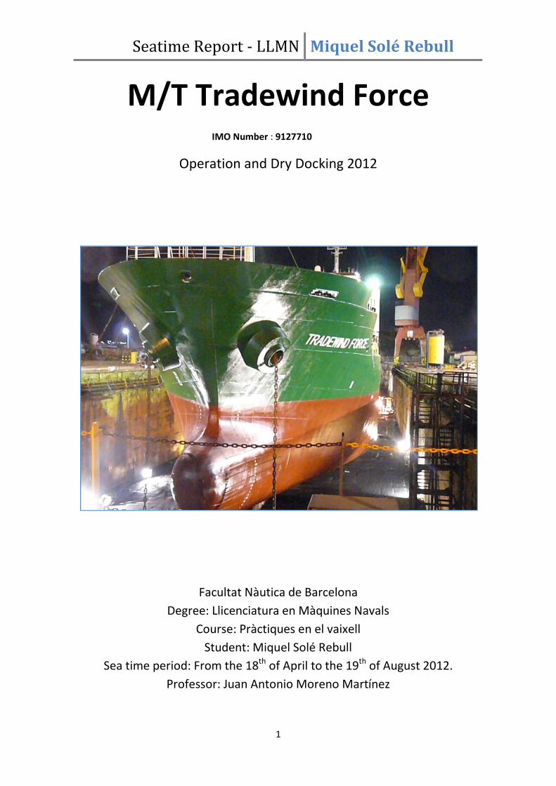
1.1 Starting procedure Fire Emergency Pump
1.- Open suction valve A 2.- Open discharger valve B
3.- Push start 4.- Check monometer gauges, the pressure is
5 kg/cm2
Note: After the starting running check there is one hydrant open on main deck

Seatime Report - LLMN Miquel Solé Rebull
9
1.2 Quick Closing Valve System Operation Procedure
To activate (Close) the valves
1.- Check pressure of bottle 7 kg/cm2.
2.- Open air valve No 1 and check the pressure on the
manometer above.
3.- Chose group of valves to be activated (No 1 - No2).
4.- Move corresponding lever to position A check in E.R..
that artic closing valves are Closed
To reset the System
1.- Move corresponding lever and return to position N
2.- Close air valve No 1
3.- Move lever to position B Check the pressure.
4.- Put and keep lever to position N
5.- Reset all quick closing valves (Open as required)

Seatime Report - LLMN Miquel Solé Rebull
10
1.3 Lifeboat Starting Procedure
1.- Open the valve of fuel oil. 2.- Turn ON battery switch 3 .- Press propeller
engaging gear and Then put the
Eng. Control lever into
Middle of neutral and max.
ahead
4.- Push engine stop lever a press 5.- After starting, put Eng. Control 6.- Astern position
running
Starting botton (max 10 sec Lever into neutral at the time)
Stop precedure
1.- Put Eng. Control Lever into Neutral (Fig. 5).
2.- Pull Out Eng. Stop Lever until engine is stopped. (fig. 4 upper hand).
3.- Turn Off battery switch (fig. 2)

Seatime Report - LLMN Miquel Solé Rebull
11
1.4 Emergency Foam Start Procedure
1.- Open Valve No 1 SW Line 2.- Open Valve No 7 3.- Check always open valve No
4 4.- Check Always open valve No 5
Through Monitor and Hydrant FOAM return
5.- Check open Valve No 6 6.- Open Suct FOAM Valve No 3 7.- Press GREEN Button to start
8.- Open Valve No 2 Through Monitor
Them check Foam Pressure
and Fire Hydrant
CAUTION.- OPEN AND / OR CLOSE OF VALVES CONDITION:
Valves No 1-2-7-8-9- & 10 Are always to be Closed Valves No 3-4-5- & 6 Are
always to be Opened

Seatime Report - LLMN Miquel Solé Rebull
12
1.5 Cold Start Procedure
1 - Start 01 generator with diesel oil and connect it to main switch board accordingly.
2.- start the boiler cold flashing of diesel oil, increase the pressure gradually
3.- open the main steam valve gradually, use service steam to heat fuel oil, lube oil & me jacket
water
5.- start the l.o. Purifier
6.- when f.o. Temperature for auxiliary engine system reaches 90 °c change over a/e to f.o.
7.- when me engine fo supply reaches about 90°c change over from d.o. To fuel oil supply
8.- lubricate manually the m.e. Cylinders
9.- engaged and turn the m.e. Turning gear
10.- inform to the bridge about readiness

Seatime Report - LLMN Miquel Solé Rebull
13
1.6 Black Out Procedure
1. Be prepared for black out in e/room with safety flash light and follow this guidelines.
2. In case of main generator stop the emergency generator will be started automatically and
put in bar in the emergency switchboard, lighting and emergency equipment should be
powered.
3. Investigate the cause of the black out problem like short fuel un the tanks, water in fuel or
valve closed, low pressure lo trip, jacket cooling fw high temperature, over speed, others.
4. After found the problem and solved it if have enough air from main air vessel, start main
generator check all parameters if it is normal and before put in bus bar disconnect emergency
switch from emergency generator after in bulbar reset all breakers and return as normal.
5. if not air available from main vessel, use emergency air bottle to raise the air pressure in
reservoir pump with emergency compressor (manual) and then start main generator as 4.
6. After check all temperature pressures are ok in the main generators, stop emergency
generator.
7. Check that all equipments and switchboards not damaged due suddenly decreasing of
voltage when have occurred the black out.
Starting procedures
1.Lubricate manually cylinders turning the lubricators.
2.Start main lub. oil pump.
3.Turn M/E with turning gear.
4.Disegage the that is locked in out position, the indicator lamp for turning gear engaged
should now go out.
5. Drain the starting air system (condensate)
6. Draine control air system from water and check pressure ( 7,0 bar)
7. Check the pressure and sight glasses of lubrication M/E and T/C.
8. Start exh. valve lub. oil pump. Check pressure
9. Check cylinder lubricators handle is in vertical position or higher position.
10. Cooling water temperature preheated 60c.check pump pressure.
11. Fuel recirculation pump running and fuel pressure and fuel preheated
at 105 c.

Seatime Report - LLMN Miquel Solé Rebull
14
12. start fuel supply pump
13. set switch for aux. blowers in position auto.
14. blow m/e with open indicators valves to ensure any water is inside cylinders put
regulating handle in start position, after one revolution,
return to stop position. telegraph should be moved to dead slow ahead/astern.
15. Close indicator valves.
16. Put telegraph ahead position.
17. Moved the regulating handle to start position turn engine with air after
some revolutions put handle delivery fuel and turn slowly dead slow revolutions.
18. Modes of starting available
A) Manual control from ecr
B) Emergency console on engine.
19. Starting with cold engine in exceptional case minimum of 20c engine temperature the rpm
should be increased slow over period of 40 min or more. Very important preheated engine all
time and keep temperature 60 c. Also very important - don’t change fuel oil. maneuvering
time used only f.o. also very impotent carefully check cylinder lubrication. Daily consumption
120 - 130 ltrs.
If starting problem or cylinder not firing need check suction valve fuel oil injector pump.
this engine is very reliable if keep all parameters. only over cooling temperature keep less 70c
maybe start crack on cyl. cover or liner. Crack cylinder liner maybe start if not enough cylinder
oil. Injectors can working 10000 hrs.
exh. valve working max. 5000 hrs. very impotent exh. valve overhaul time check valve
spindled valve seat by caliper angel seat and spindled is different. Also necessary keep under
control turn exh. valve turn mech.

Seatime Report - LLMN Miquel Solé Rebull
15
1.7 Black up procedure
Zone Diesel Generator
1.- Open Air Supply Valve. 2.- Open D.O. Suction and discharge
valve of emergency D.O. pump
3.- Put the switch in position “ON” 4.-Start Aux. Eng. With Push botton of
The emergency D.O. pump. (In the CER) The starting control valve, before check
control level is in intermediate position
between STOP and RUN

Seatime Report - LLMN Miquel Solé Rebull
16
In the engine control room
5.- Plush to close air circuit Breaker. 6 Change over running emergency D.O.
pump to or switch to close ABC control switch
auxiliary engine D.O. flushing pump
7.- Run L.T. cool pump.
8.-Run Center Cool Sea Water Pump

Seatime Report - LLMN Miquel Solé Rebull
17
PART 2: FRESH WATER PRODUCTION INCREMENT REPORT
During the inspection and operation of the Fresh Water Generator (FWG) JWSP-26-C100
installed on-board, the following observations and faults were found.
Observation /Fault finding:
� Extremely Low Production 7 to 9 m3 a day representing about a 22 to 28% of the
maximum production specified into the manual.
� Insufficient vacuum
� The Jacket water outlet from main engine to the evaporator side was being passed
through the heater before the FWG which was excessively being heated by steam.
� Incorrect vacuum gauge ( maximum vacuum reading 0.8 bar, reading required 1 bar)
� High separator vessel temperature.
� The separator vessel was not opened for a long period of time.
� The FWG could be operated using the General Service Pump when the Ejector Pump
fails, but there is no valve on the discharge side of the FWG ejector pump.
Since the FWG is an essential element on-board to maintain the fresh water level for the
correct operation of the ship, the following work was performed to increase the fresh water
production.
Work performed previous to open the separator vessel:
� Chemical recirculation on the condenser and evaporator plates.
Observations and deficiencies found when dismantling the FWG
� Several plates wrongly fitted
� Defective plates due to previous wrong assembly and over-tightening
� The plate gaskets were in very poor conditions, deteriorated and deformed.
� Both pressure plates were bended due to over-tightening.
� Clearance between the plates was insufficient due to over-tightening.
� Big scale accumulations which nearly blocked the passages.
� Excessive clearance between the impeller and the wear ring in the distillated pump.
� Small hole on the suction pipe of the FWG ejector pump.
� Zinc anodes were found in un-satisfactory conditions.
Work performed on the Fresh Water Generator
� Dismantlement the front cover.
� Dismantlement of the distilled pump.
� Dismantle the condenser and evaporator plates for cleaning and inspection.
� Evaporator plates were completely submerged into a hot, inhibited acid bath.
� Condenser plates were scrubbed with a soft brush and plain hot water.
� Reassembling of the plates.

Seatime Report - LLMN Miquel Solé Rebull
18
� Fabrication of a new mount ring for the distillated pump.
� Reassembled all components.
� Pressure tested the condenser and evaporator.
� Pressure tested the separator vessel.
� Zinc anodes were changed.
� Incremented the amperage of the tripping device from 30 A to 32 A in the Ejector
Pump.
� Thermometer was changed due to leaking during the pressure test.
� FWG ejector pump suction pipe hole was repaired.
Actual Fresh Water Production
After the work performed above, the actual daily production of fresh water is approximately
20 to 21m3. This figure represents an increment on the production around 12 to 14 m3 per
day.
Even thought the actual fresh water production is considerably higher than the previous
production (286% higher). It is the 63% of the maximum production specified into the
manufacturer manual. Therefore, we recommend the following actions in order to increase
the fresh water production and properly maintain the Fresh Water Generator System.
Recommendations
� Substitute the plate gaskets for new ones.
� Realign the pressure plates after receiving the plate gaskets.
� Install new vacuum gauge.
� Renew several heat exchanger plates on both evaporator and condenser.
� Install a valve after FWG ejector pump for correct operation of the system with the
General Service Pump.
Image 1: Fresh Water Generator (Alfa Laval JWSP-26-C100) installed on the M/T Tradewind
Force.

Seatime Report - LLMN Miquel Solé Rebull
19
Image 2: Detail of the Evaporator Pressure Plate Bending
Image 3: Scale piece with a substantial size.
Pressure Plate Bending

Seatime Report - LLMN Miquel Solé Rebull
20
Image 4: Detail on the condition of the evaporator heat-transfer titanium plates and gaskets.
Image 5: Detail on the state of the Zinc anodes

Seatime Report - LLMN Miquel Solé Rebull
21
PART 3: CSM (CONTINUOUS SURVEY ON MACHINERY)
With the purpose of have credited the maximum amount of items in the CSM (Continuous
Survey on Machinery).
A rocking test on the main crane for crediting the Cargo Gear Item by the Class was due the
23th of June 2012. As per the superintendent instructions, the Chief engineer planned to
inspect and overhaul the following items:
Date Element Surveyed: class’ society nomenclature (Onboard nomenclature)
04/06/2012 Fuel Oil Purifier Pump #2 Feed (FO Purifier Feed Pump #2)
07/06/2012 Lube Oil Pump #2 Feed (LO Purifier Feed Pump #2)
08/06/2012 Aux. Boiler Feed Pump No. 02 (Boiler Main Feed Water Pump #2)
06/06/2012 Cargo Tank Cleaning Warm Up Heater No.1 (Tank Cleaning Heater #1)
14/06/2012 Cargo Tank Cleaning Warm Up Heater No.1 – Press. Test (Pressure Test of
Tank Cleaning Heater #1)
07/06/2012 Cargo Tank Cleaning Warm Up Heater No.2 (Tank Cleaning Heater #2)
14/06/2012 Cargo Tank Cleaning Warm Up Heater No.1 – Press. Test (Pressure Test of
Tank Cleaning Heater #1)
18/06/2012 Fresh Water Pump No.2 (Fresh Water Pump #2)
18/06/2012 Main Fresh Water Circulating Pump No.2 Hot Water (#2 Main Hot Water
Circulating Pump)
16/06/2012 Diesel Oil Pump 2d/Gflush (D/G #2 Diesel Oil Flushing Pump)
19/06/2012 Purifier No.2 for Fuel Oil (#2 F.O. Purifier)
18/06/2012 Pump Sludge (Sludge pump)
16/06/2012 Bilge Separator (Oil Water Separator)
21/06/2012 Sea Chests (High and Low Sea Chest)
20/06/2012 Bilge Piping (Bilge Piping)
21/06/2012 Bilge Suction Valves (Bilge Suction Valves)
18/06/2012 Bilge wells eachcgtank (Port Bilge Well, Stbd Bilge Well and Aft Bilge Well)
21/06/2012 Boiler Feed Water Piping (Boiler Feed Water Piping)
21/06/2012 Condensate Piping (Condensate Piping)
21/06/2012 Starting Air Piping (Starting Air Piping)
21/06/2012 Starting Air System (Starting Air System)
21/06/2012 Stern Tube Lubricating Piping (Steam Tube Lubricating Piping)
12/06/2012 Aux. Boiler F.O. Pump No.2 (Aux Boiler Heavy Fuel Oil Pump #2)
21/06/2012 Cargo Transfer Control System Emergency Shutdown System
19/06/2012 Aux. Generator No.1
19/06/2012 Main Power Distribution System
17/06/2012 Alarms for Fire Detection System
19/06/2012 Aux. Generator No.01 – Megger Reading
19/06/2012 Aux. Generator No.01 – Ops. Test
20/06/2012 Aux. Generator No.02 – Megger Reading

Seatime Report - LLMN Miquel Solé Rebull
22
20/06/2012 Aux. Generator No.02 – Ops. Test
20/06/2012 Aux. Generator No.03 – Megger Reading
20/06/2012 Aux. Generator No.03 – Ops. Test
20/06/2012 Aux. Switchboard
20/06/2012 Electric Fixtures
20/06/2012 Generator Trip No.1 – Reverse Power Protection
20/06/2012 Generator Trip No.1 – Under Voltage Protection
19/06/2012 Generator Trip No.1 – Reverse Power Protection
19/06/2012 Generator Trip No.1 – Under Voltage Protection
19/06/2012 Generator Trip No.1 – Reverse Power Protection
19/06/2012 Generator Trip No.1 – Under Voltage Protection
Sludge Pump
Date: 18 June 2012
Inspected and Overhauled; found in satisfactory conditions.

Seatime Report - LLMN Miquel Solé Rebull
23
Fresh Water Pump No.2
Date: 18 June 2012
Inspected and Overhauled; found in satisfactory conditions.
Main Fresh Water Circulating Pump No.2
Date: 18 June 2012
Inspected and Overhauled; found in satisfactory conditions.

Seatime Report - LLMN Miquel Solé Rebull
24
Bilge Wells, eachcgtank
Date: 18 June 2012
Cleaned and Inspected. Found in satisfactory conditions.
Purifier No.2 for Fuel Oil
Date: 19 June 2012
Inspected and Overhauled; found in satisfactory conditions.

Seatime Report - LLMN Miquel Solé Rebull
25
Purifier No.2 for Fuel Oil
Date: 19 June 2012
Inspected and Overhauled; found in satisfactory conditions.
Purifier No.2 for Fuel Oil
Date: 19 June 2012
Inspected and Overhauled; found in satisfactory conditions.

Seatime Report - LLMN Miquel Solé Rebull
26
Main Alternator No.2
Date: 19 June 2012
Inspected and Overhauled; found in satisfactory conditions.
Filter before Control Air Pressure Reducing Valvel
Date: 19 June 2012
Inspected and Overhauled; found in satisfactory conditions.

Seatime Report - LLMN Miquel Solé Rebull
27
PART 4:EXAMPLES FOR CORRECT ENTRIES IN THE OIL RECORD
BOOK
The following is recorded in the supplement to the IOPP Certificate (Form B) – Record of
construction and equipment for oil tanker):
3.1 The ship is provided with oil residue (sludge) tanks as follows:
Sludge Tank – 15.4 m3
Separated Oil Tank – 15.3 m3
Incinerator Waste Oil tank – 1.0 m3
3.2 Means for the disposal of oil residues in addition to the provision of sludge tanks:
Incinerator for oil residues; capacity 20 l/h
Evaporation of water from Incinerator Waste Oil tank
3.3 The ship is fitted with oil holding tank(s) for the retention on board of oily bilge water as
follows:
Bilge Water Holding Tank – 28.9 m3.
OWS Capacity 5.0 m3.
Guidance on sludge quantity to be reported:
1. Quantity of fuel oil sludge produced should be equivalent to 1–2% of the heavy fuel oil
burned. (USCG)
2. Sludge daily quantity should be equivalent to (0.8% -1%) of HFO daily consumption + 0.5%
of DO daily consumption. (MARPOL)
3. Sludge on board = sludge produced – sludge incinerated (Intertanko)
DATE CODE
(LETTER)
ITEM
(NUMBER)
RECORDS OF OPERATIONS / SIGNATURE OF OFFICER IN
CHARGE
Date
(weekly)
C 11.1 Sludge Tank
11.2 15.4 m3
11.3 3.9 m3
11.1 Separated Oil Tank
11.2 15.3 m3
11.3 0.7 m3
11.1 Incinerator Waste Oil tank

Seatime Report - LLMN Miquel Solé Rebull
28
DATE CODE
(LETTER)
ITEM
(NUMBER)
RECORDS OF OPERATIONS / SIGNATURE OF OFFICER IN
CHARGE
11.2 1.0 m3
11.3 0.4 m3
I Bilge Water Holding Tank, Capacity 28.9 m3, Total quantity
of retention 22.0 m3
Date, Officer’s in charge & Chief Engineer Signatures
Date C 12.1 3.0 m3 sludge disposed from Sludge Tank to Hamburg port
facilities. Quantity retained in Sludge tank 0.9 m3
Signature
Date C 12.2 0.5 m3 sludge transferred from Separated Oil Tank to
Incinerator Waste Oil tank. Quantity retained in Separated
Oil Tank 0.2 m3. Total content in Incinerator Waste Oil Tank
0.9 m3.
Signature
Date C 12.2 0.3 m3 water drained from Incinerator Waste Oil tank to
Bilge Water Holding Tank. Quantity retained in Incinerator
Waste Oil Tank 0.6m3. Total content in tank 22.0m
3.
Signature
Date C 12.3 0.4m3 sludge incinerated from Incinerator Waste Oil tank.
Total time of operation 20 hours. Quantity retained in
Incinerator Waste Oil Tank 0.2m3.
Date C 12.4 0.1m3 water evaporated from Incinerator Waste Oil tank.
Quantity retained in Incinerator Waste Oil Tank 0.1m3.
Signature
Date D 13. 10.0 m3 from Bilge Water Holding Tank, Capacity of tank
28.9 m3. Quantity retained in Bilge Water Holding Tank
12.0 m3.
14. Started 08:00, Stopped 10:20
15.1 Through 15 ppm equipment
Position at start:
Position at end:
C 12.2 0.1 m3 from 15 ppm equipment operation to Sludge Tank.
Total content in Sludge Tank 1.0 m3
Signature
Date D 13. 4.0 m3 from Bilge Water Holding Tank, Capacity of tank 28.9
m3. Quantity retained in Bilge Water Holding Tank 8.0 m
3.
14. Started 08:00, Stopped 09:10
15.2 Bilge water discharged to Antwerpen reception facility.
Signature
Date D 13. 2.0 m3 from ER bilges
14. Started 08:00, Stopped 08:15
15.3 Bilge water discharged to Bilge Water Holding Tank. Capacity
of tank 28.9 m3. Quantity retained in Bilge Water Holding
Tank 10.0 m3.
Signature

Seatime Report - LLMN Miquel Solé Rebull
29
DATE CODE
(LETTER)
ITEM
(NUMBER)
RECORDS OF OPERATIONS / SIGNATURE OF OFFICER IN
CHARGE
Date D 13. 3.0 m3 from Bilge Water Holding Tank. Capacity of tank 28.9
m3. Quantity retained in Bilge Water Holding Tank 7.0 m
3.
14. Started 09:00, Stopped 11:00
15.3 3.0 m3 discharged from Bilge Water Holding Tank to Slop
Tank portside. Quantity retained in Slop Tank portside
125.0 m3.
Signature
Date H 26.1 Amsterdam
26.2 Started 10:00, Finished 12:30
26.3 300.0 mt HFO360 to Deep Tank (P). Total content in tank 310
mt.
350.0 mt HFO 360 to Deep Tank (Stbd). Total content in tank
360.0 mt.
Signature
Date H 26.1 Amsterdam
26.2 Started 10:00, Finished 12:30
26.4 1.0 mt Mobilgard 357 to Lub Oil Tank (P). Total content in tank
1.5 mt.
2.0 mt Mobilgard 358 to Lub Oil Tank (Stbd). Total content in
tank 2.7 mt.
Signature
Date
(no later
than 24 hrs
prior
arrival)
I Operational test of OWS and associated equipment carried
out. It found in a good order.
Signature
Date
(prior
arrival)
I OWS overboard discharge valve closed and sealed with seal
number 123456
Signature
Date
(prior
arrival)
I OWS overboard discharge valve closed and secured by padlock
Signature
Date
(as per
PMP)
I ER emergency suction valve seal was removed in order to
ensure the valve is free. Thereafter the valve closed and
secured with seal No.12345
Signature
Date
(if any
work
performed)
I Valves and piping on discharge side of OWS opened, inspected
and cleaned. After maintenance OWS and Oil Content Meter
checked for proper operation and found in order.
Signature
Date
(every 2
months)
I OWS opened, inspected and cleaned. After maintenance OWS
and Oil Content Meter checked for proper operation and
found in order

Seatime Report - LLMN Miquel Solé Rebull
30
DATE CODE
(LETTER)
ITEM
(NUMBER)
RECORDS OF OPERATIONS / SIGNATURE OF OFFICER IN
CHARGE
Signature
Date
(every 2
months)
I Bilge holding tank cleaned.
Signature
Date
(monthly)
I OWS filter cleaned (or renewed as required). After
maintenance OWS and Oil Content Meter checked for proper
operation and found in order.
Signature
Date
(annually)
I Sample landed for testing in a shore laboratory
Signature
Date
(annually)
I The Oil Content Meter calibrated and found in good order
Signature
Date
(on
entering /
exiting a
SECA)
I Time
Position when changeover was started
Position when changeover was completed
Quantities of low sulphur fuels in each tank
Signature
Date I Time
20 kgs oily rags were burnt
Signature
These are only examples for the most common operations in the engine room concerning sludge
and bilge water. For all other see List of Items in your ORB.
NOTE: New entry C11.4 – Quantity of residue collected by manual operation in M3. This new entry is
required as from 1 December 2010. The current onboard ORB does not have a C11.4 entry. (Ref:
Intertanko guide 2009, 2nd
edition)

Seatime Report - LLMN Miquel Solé Rebull
31
PART 5: DRY DOCKING
The dry docking of a Vessel could itself be a extensive report, but for the scope of this one it
would be just the checklist prior to arrival and the Dry Dock shut Down Plan.
Superintendent’s Pre-Arrival to Dry Dock Check list.
Item Description
1 To Designate a Conference Room
2 To Fully Brief the Crew
3 Sufficient Padlocks?
4 To take down tools shadow boards and secure tools, chemicals, O2 and C2H2
5 To mark with “NO HOT WORK PERMITTED” all tanks and fuel tank vents
6 To identify the location of TAIL-SHAFT WEAR DOWN GAUGE
7 To identify the location and fitting for the provision of shore power
8 To identify the location and fitting for the provision of shore cooling water for
reefer and A/C plants.
9 To identify task to be performed bye, YARD and SHIP STAFF
10 To fully inspect the vessel’s pipe-work
11 To gas free Cargo Tanks
12 To Prepare a SHUTDOWN PLAN
13 All ballast tanks to be de-mucked and kept free of mud
14 All void spaces and cofferdam manhole doors should be opened or kept on
minimum bolts for inspection for gas fee condition.
15 Cargo tank steam lines to be vented
16 When the main engine has cooled down, al l relevant engine pumps and standby
pumps are to be isolated and the fuses removed, alternatively the starter panel
isolators should be padlocked in the “off” postion.
17 Both main air start bottles are to be topped up to maximum working pressure and
fully isolated after main engine shut down. Bottle valves to be chained in “closed”
condition. This should be also done for any generator start air/accumulator bottles
and emergency air start accumulators.
18 The boiler should be shut down in sufficient time, on diesel, and be cool enough,
pressure down, to allow complete blow down of boiler water before the dry-dock
is pumped dry. When cool enough and devoid of any pressure, all manhole doors
should be opened to allow ventilation. The burner should be swung out and the
protective cover applied and the boiler panel isolated.
19 Main deck, accommodation decks and the accommodation superstructure to be
well cleaned with fresh water.
20 A list of work to be carried out by the Ship’s staff during the drydocking and repair
period is to be drawn up and available to the vessel’s superintendent on arrival.
21 While the vessel is afloat the ship’s power is to be available and Engine Room
watches maintained accordingly
22 All concerned Fuel Oil tanks including the settling and service tanks to be cleaned
emptied and gas free before arriving to the Dry Dock.
23 Main deck, accommodation decks and the accommodation superstructure to be
well cleaned with fresh water.
24 Prepare SAF16 for pre-arrival to the Dry Dock and during Dry Docking. TEC 26 form
for departure Dry Dock.
25 The vessel must arrive to Curacao with COT and CO lines clean and gas free

Seatime Report - LLMN Miquel Solé Rebull
32
26 Vessel to keep in contact with local agency advising ETA & slop discharge services
required.
27 Vessel must arrive ready with clear spaces where hot-works must take place as per
Dry Dock specifications, all flammable products and stuff to be removed for safety
and prompt developments making easy Shipyard work.
28 Vessel shall deploy boards/stickers/stencils alerting about the places where hot
works are not permitted.
29 CDM(Curacao Dry Dock) must be inform trim requirements with enough time prior
entering in the Dry Dock in order to adjust Water Ballast accordingly and not in
excess.
30 Dry Docking Vships Check List to be discussed and performed prior enter into the
Dry Dock
31 Vessel to inform about expected amount the mud inside chain lockers and clarify
chain links studs missing
32 Prior arrival all COT Heating coils must be ready/accessible to take LEL content
from authorized marine chemist (best if C/O can do own test before arrival)
33 Safety precautions from Ship Staff to be taken as per Vships Dry Dock procedures,
to record any document and file.
34 Air vents shall be protected by rags/filter in order to avoid the grit accessing to
tanks (specially bunker/oil tanks)
35 PVV to be protected and covered by plastic bags
36 Low tier windows to be protected by cartons from grit impact and paint
37 To lay paper Kraft on the alleyways, duty offices like CCR and stairs
38 Officers must be very aware about works affecting their departments in order to
guide their Crew, Shipyard workers and report progress accordingly
39 C/O to have a ready the spanner for WBT bottom plugs for de-ballasting
40 All local shore services to be well coordinated prior Vessel arrival

Seatime Report - LLMN Miquel Solé Rebull
33
Seatime Report - LLMN Miquel Solé Rebull
34
PART 6: REFERENCES
� Hyundai MAN and B&W Manuals for Low Speed Engine 6L35MC
� Alfa Laval – Fresh Water Generator JPSW-26 C100
� Alfa Laval – LO/FO/DO Purifiers MOPX-MFOX
� VSHIPS MANAGING SYSTEM
� ABS CLASS information