Seamless mobility in 4G systems · Abstract The proliferation of radio access technologies,...
141
Technical Report Number 656 Computer Laboratory UCAM-CL-TR-656 ISSN 1476-2986 Seamless mobility in 4G systems Pablo Vidales November 2005 15 JJ Thomson Avenue Cambridge CB3 0FD United Kingdom phone +44 1223 763500 http://www.cl.cam.ac.uk/
Transcript of Seamless mobility in 4G systems · Abstract The proliferation of radio access technologies,...

Technical ReportNumber 656
Computer Laboratory
UCAM-CL-TR-656ISSN 1476-2986
Seamless mobility in 4G systems
Pablo Vidales
November 2005
15 JJ Thomson Avenue
Cambridge CB3 0FD
United Kingdom
phone +44 1223 763500
http://www.cl.cam.ac.uk/

c© 2005 Pablo Vidales
This technical report is based on a dissertation submittedMay 2005 by the author for the degree of Doctor ofPhilosophy to the University of Cambridge, Girton College.
Technical reports published by the University of CambridgeComputer Laboratory are freely available via the Internet:
http://www.cl.cam.ac.uk/TechReports/
ISSN 1476-2986

Abstract
The proliferation of radio access technologies, wireless networking devices, and mobileservices has encouraged intensive nomadic computing activity. When travelling, mobileusers experience connectivity disturbances, particularly when they handoff between twoaccess points that belong to the same wireless network and when they change from oneaccess technology to another. Nowadays, an average mobile user might connect to manydifferent wireless networks in the course of a day to obtain diverse services, whilst demand-ing transparent operation. Current protocols offer portability and transparent mobility,however, they fail to cope with huge delays caused by different link-layer characteristicswhen roaming between independent disparate networks. In this dissertation, I addressthis deficiency by introducing and evaluating practical methods and solutions that min-imise connection disruptions and support transparent mobility in future communicationsystems.
Firstly, I show that repercussions on the link can be minimised by using the appro-priate architecture. Recently, it has been considered necessary to integrate commercially-available wireless networks into a universal access platform, also known as the fourthgeneration (4G) communication system. I present the design and deployment of an ex-perimental testbed that implements this 4G model, enabling roaming between the mostpopular wireless and wired technologies. In addition, the testbed is used to evaluate Mo-bile IPv6 performance in heterogeneous environments, and identify the weaknesses of thisprotocol to manage seamless roaming between different technologies.
Secondly, I demonstrate that Mobile IPv6 can be optimised by modifying its currentspecification without altering the core functionality or adding significant overhead. Myexperimental results show the improvements in vertical handover latency, which variedbetween small time reductions and “zero” latency, for the case of soft handovers.
Finally, I claim that minimising the latency is not enough to enable seamless roamingin highly-integrated and diverse networks. Therefore, I show the design and implemen-tation of PROTON, a policy-based solution to assist nomadic users. To validate thestrength of my proposal, I evaluate PROTON using the testbed, and demonstrate that itis possible to offer suitable mobility support in next generation systems, whilst handlingthe complexities and dynamic behaviour posed by the environment.

4

Contents
1 Introduction 131.1 Terminology . . . . . . . . . . . . . . . . . . . . . . . . . . . . . . . . . . . 131.2 Motivation . . . . . . . . . . . . . . . . . . . . . . . . . . . . . . . . . . . . 151.3 Contribution . . . . . . . . . . . . . . . . . . . . . . . . . . . . . . . . . . . 161.4 Outline of the rest of the dissertation . . . . . . . . . . . . . . . . . . . . . 17
2 Mobility Management Overview 192.1 IPv6: Next generation Internet protocol . . . . . . . . . . . . . . . . . . . 192.2 Terminal mobility . . . . . . . . . . . . . . . . . . . . . . . . . . . . . . . . 22
2.2.1 Mobile IPv6: How does it work? . . . . . . . . . . . . . . . . . . . . 222.3 Terminal mobility protocols . . . . . . . . . . . . . . . . . . . . . . . . . . 23
2.3.1 Micro-mobility solutions . . . . . . . . . . . . . . . . . . . . . . . . 252.3.2 Macro-mobility solutions . . . . . . . . . . . . . . . . . . . . . . . . 26
2.4 Policy models to enable seamless mobility . . . . . . . . . . . . . . . . . . 27
3 The LCE-CL Experimental Setup 313.1 Integration techniques . . . . . . . . . . . . . . . . . . . . . . . . . . . . . 32
3.1.1 OSI-layer integration . . . . . . . . . . . . . . . . . . . . . . . . . . 333.1.2 Networking-component integration . . . . . . . . . . . . . . . . . . 333.1.3 OSI-functionality integration . . . . . . . . . . . . . . . . . . . . . . 34
3.2 The testbed . . . . . . . . . . . . . . . . . . . . . . . . . . . . . . . . . . . 353.3 Related work . . . . . . . . . . . . . . . . . . . . . . . . . . . . . . . . . . 363.4 Hardware . . . . . . . . . . . . . . . . . . . . . . . . . . . . . . . . . . . . 39
3.4.1 The Sentient Car . . . . . . . . . . . . . . . . . . . . . . . . . . . . 403.5 Software . . . . . . . . . . . . . . . . . . . . . . . . . . . . . . . . . . . . . 41
3.5.1 Operational software . . . . . . . . . . . . . . . . . . . . . . . . . . 423.5.2 Analysis tools . . . . . . . . . . . . . . . . . . . . . . . . . . . . . . 42
3.6 Remarks . . . . . . . . . . . . . . . . . . . . . . . . . . . . . . . . . . . . . 43
4 Evaluation and Networking Improvements for 4G Systems 454.1 Optimisations to Mobile IPv6 . . . . . . . . . . . . . . . . . . . . . . . . . 464.2 Experimental environment . . . . . . . . . . . . . . . . . . . . . . . . . . . 474.3 Experiments to evaluate MIPv6 . . . . . . . . . . . . . . . . . . . . . . . . 48
4.3.1 Mobile IPv6 network layer performance (IP) . . . . . . . . . . . . . 484.3.2 Mobile IPv6 transport layer performance (UDP) . . . . . . . . . . . 494.3.3 Mobile IPv6 impact on the transport layer (TCP) . . . . . . . . . . 504.3.4 Packet overhead . . . . . . . . . . . . . . . . . . . . . . . . . . . . . 51
5

4.4 Vertical handover latency characterisation . . . . . . . . . . . . . . . . . . 52
4.4.1 Analytical representation of latency partition . . . . . . . . . . . . 54
4.4.2 Experimental latency partition . . . . . . . . . . . . . . . . . . . . 56
4.5 Impacting MIPv6 latency . . . . . . . . . . . . . . . . . . . . . . . . . . . 60
4.5.1 RA frequency . . . . . . . . . . . . . . . . . . . . . . . . . . . . . . 60
4.5.2 RA caching . . . . . . . . . . . . . . . . . . . . . . . . . . . . . . . 61
4.5.3 BU simulcasting . . . . . . . . . . . . . . . . . . . . . . . . . . . . . 61
4.5.4 Soft handover . . . . . . . . . . . . . . . . . . . . . . . . . . . . . . 62
4.6 Related work . . . . . . . . . . . . . . . . . . . . . . . . . . . . . . . . . . 64
4.7 Remarks . . . . . . . . . . . . . . . . . . . . . . . . . . . . . . . . . . . . . 65
5 Autonomic System for Future Networks 67
5.1 The Problem: Seamless complexity . . . . . . . . . . . . . . . . . . . . . . 68
5.1.1 Autonomic solution for 4G systems . . . . . . . . . . . . . . . . . . 69
5.1.2 A novel approach . . . . . . . . . . . . . . . . . . . . . . . . . . . . 70
5.2 Architecture . . . . . . . . . . . . . . . . . . . . . . . . . . . . . . . . . . . 70
5.2.1 Network-side components . . . . . . . . . . . . . . . . . . . . . . . 71
5.2.2 Host-side components . . . . . . . . . . . . . . . . . . . . . . . . . . 72
5.3 Networking Context . . . . . . . . . . . . . . . . . . . . . . . . . . . . . . 73
5.4 Policy model . . . . . . . . . . . . . . . . . . . . . . . . . . . . . . . . . . . 74
5.4.1 Policy specification . . . . . . . . . . . . . . . . . . . . . . . . . . . 75
5.4.2 An evaluation model based on FSTs . . . . . . . . . . . . . . . . . 75
5.4.3 Modelling policies with TFFSTs . . . . . . . . . . . . . . . . . . . . 78
5.5 Processes . . . . . . . . . . . . . . . . . . . . . . . . . . . . . . . . . . . . 80
5.5.1 Policy translation . . . . . . . . . . . . . . . . . . . . . . . . . . . . 80
5.5.2 Conflict resolution . . . . . . . . . . . . . . . . . . . . . . . . . . . 81
5.5.3 Model distribution . . . . . . . . . . . . . . . . . . . . . . . . . . . 82
5.5.4 Context gathering . . . . . . . . . . . . . . . . . . . . . . . . . . . . 83
5.5.5 Policy evaluation . . . . . . . . . . . . . . . . . . . . . . . . . . . . 84
5.5.6 Tautness function computation . . . . . . . . . . . . . . . . . . . . 84
5.5.7 Policy enforcement . . . . . . . . . . . . . . . . . . . . . . . . . . . 85
5.6 Remarks . . . . . . . . . . . . . . . . . . . . . . . . . . . . . . . . . . . . . 86
6 Evaluation 89
6.1 Test case . . . . . . . . . . . . . . . . . . . . . . . . . . . . . . . . . . . . . 90
6.1.1 Test case inputs . . . . . . . . . . . . . . . . . . . . . . . . . . . . . 91
6.1.2 Case discussion . . . . . . . . . . . . . . . . . . . . . . . . . . . . . 92
6.2 Resource usage and overheads . . . . . . . . . . . . . . . . . . . . . . . . . 92
6.2.1 TFFST construction . . . . . . . . . . . . . . . . . . . . . . . . . . 93
6.2.2 TFFST distribution . . . . . . . . . . . . . . . . . . . . . . . . . . . 93
6.2.3 TFFST computation . . . . . . . . . . . . . . . . . . . . . . . . . . 95
6.3 Feasibility of deployment . . . . . . . . . . . . . . . . . . . . . . . . . . . . 98
6.4 Scalability . . . . . . . . . . . . . . . . . . . . . . . . . . . . . . . . . . . . 101
6.5 Qualitative analysis . . . . . . . . . . . . . . . . . . . . . . . . . . . . . . . 102
6.5.1 System comparison . . . . . . . . . . . . . . . . . . . . . . . . . . . 104
6

7 Conclusion 1077.1 Summary . . . . . . . . . . . . . . . . . . . . . . . . . . . . . . . . . . . . 1077.2 Future research . . . . . . . . . . . . . . . . . . . . . . . . . . . . . . . . . 108
A Glossary 111A.1 Definition of terms and concepts . . . . . . . . . . . . . . . . . . . . . . . . 111A.2 Nomenclature . . . . . . . . . . . . . . . . . . . . . . . . . . . . . . . . . . 115
B Policy Evaluation and Conflict Resolution 121B.1 Transducers and Tautness functions . . . . . . . . . . . . . . . . . . . . . . 121
B.1.1 Recognisers . . . . . . . . . . . . . . . . . . . . . . . . . . . . . . . 121B.1.2 Transducers . . . . . . . . . . . . . . . . . . . . . . . . . . . . . . . 122B.1.3 Tautness functions . . . . . . . . . . . . . . . . . . . . . . . . . . . 122
B.2 An Algebra for Tautness Functions . . . . . . . . . . . . . . . . . . . . . . 123B.3 Transducers with Tautness Functions and Identities . . . . . . . . . . . . . 124B.4 Operations on TFFST . . . . . . . . . . . . . . . . . . . . . . . . . . . . . 127
B.4.1 Identity . . . . . . . . . . . . . . . . . . . . . . . . . . . . . . . . . 127B.4.2 Union . . . . . . . . . . . . . . . . . . . . . . . . . . . . . . . . . . 127B.4.3 Intersection . . . . . . . . . . . . . . . . . . . . . . . . . . . . . . . 128B.4.4 Complement . . . . . . . . . . . . . . . . . . . . . . . . . . . . . . . 128
B.5 Conflict resolution . . . . . . . . . . . . . . . . . . . . . . . . . . . . . . . 129B.5.1 Composition . . . . . . . . . . . . . . . . . . . . . . . . . . . . . . . 129B.5.2 Determinisation . . . . . . . . . . . . . . . . . . . . . . . . . . . . . 130
Bibliography 132
7

8

List of Figures
1.1 Handover taxonomy and views. . . . . . . . . . . . . . . . . . . . . . . . . 14
2.1 The evolution of mobile computing. . . . . . . . . . . . . . . . . . . . . . . 202.2 Networking evolution and driver protocols. . . . . . . . . . . . . . . . . . . 212.3 Basic Mobile IPv6 case example. . . . . . . . . . . . . . . . . . . . . . . . 22
3.1 Taxonomy according to the integration layer. . . . . . . . . . . . . . . . . . 323.2 Integration Models: Depending on the integration components. . . . . . . . 343.3 LCE-CL testbed and MIPv6 entities. . . . . . . . . . . . . . . . . . . . . . 383.4 Network-centric view of the LCE-CL testbed. . . . . . . . . . . . . . . . . 403.5 The Sentient Car. . . . . . . . . . . . . . . . . . . . . . . . . . . . . . . . . 41
4.1 MIPv6 network layer vertical handover latency. . . . . . . . . . . . . . . . 494.2 UDP over MIPv6 vertical handover latency. . . . . . . . . . . . . . . . . . 494.3 MIPv6 transport layer (TCP) vertical handover latency. . . . . . . . . . . 504.4 Packet overhead for different types of payloads. . . . . . . . . . . . . . . . 524.5 Adaptation component for the test scenario WLAN-to-GPRS. . . . . . . . 534.6 Network and transport layers’ latency partition. . . . . . . . . . . . . . . . 544.7 Close-up of a handover showing the effects of excess buffering. . . . . . . . 574.8 Lazy cell switching. . . . . . . . . . . . . . . . . . . . . . . . . . . . . . . . 584.9 Eager cell switching. . . . . . . . . . . . . . . . . . . . . . . . . . . . . . . 594.10 Soft GPRS-WLAN handover. . . . . . . . . . . . . . . . . . . . . . . . . . 63
5.1 Future 4G communication system. . . . . . . . . . . . . . . . . . . . . . . . 685.2 PROTON’s architecture. . . . . . . . . . . . . . . . . . . . . . . . . . . . . . 715.3 Networking Context components. . . . . . . . . . . . . . . . . . . . . . . . . 735.4 Translation process. . . . . . . . . . . . . . . . . . . . . . . . . . . . . . . . 775.5 TFFST model for the obligation in Rule 2. . . . . . . . . . . . . . . . . . 785.6 TFFST model for the constraint in Rule 3. . . . . . . . . . . . . . . . . . . 795.7 TFFST model for composition of rules 2 and 3. . . . . . . . . . . . . . . . 805.8 Model distribution process. . . . . . . . . . . . . . . . . . . . . . . . . . . . 805.9 Determinisation process. . . . . . . . . . . . . . . . . . . . . . . . . . . . . 825.10 Handover Executor implementation. . . . . . . . . . . . . . . . . . . . . . . 86
6.1 Testing PROTON in a simulated scenario. . . . . . . . . . . . . . . . . . . 906.2 Resource usage. . . . . . . . . . . . . . . . . . . . . . . . . . . . . . . . . . 936.3 Travelled distances between updates. . . . . . . . . . . . . . . . . . . . . . 976.4 Maximum number of transition for each mobility profile. . . . . . . . . . . 99
9

6.5 Upper bound on the out-degree for different numbers of conditions. . . . . 100
B.1 Transducer representing division by 3 of binaries numbers . . . . . . . . . . 122B.2 Before determinisation . . . . . . . . . . . . . . . . . . . . . . . . . . . . . 130B.3 After determinisation procedure . . . . . . . . . . . . . . . . . . . . . . . . 131
10

List of Tables
2.1 Host mobility support. . . . . . . . . . . . . . . . . . . . . . . . . . . . . . 25
3.1 Diversity in existing and emerging wireless technologies. . . . . . . . . . . . 313.2 The LCE-CL testbed enables three multi-mode devices. . . . . . . . . . . . 39
4.1 Latency partition for vertical handovers using MIPL(milliseconds). . . . . . 564.2 RA frequency variation effects on WLAN and GPRS networks. . . . . . . . 604.3 BU-simulcasting reduction (best case analysis). . . . . . . . . . . . . . . . 61
5.1 Complexities in 4G systems compared to homogeneous environments. . . . 695.2 CML components, context fragments, and generated events. . . . . . . . . 83
6.1 Aggressive distribution policy. . . . . . . . . . . . . . . . . . . . . . . . . . 946.2 Conservative distribution policy. . . . . . . . . . . . . . . . . . . . . . . . . 956.3 Processing time for three-level and polling tasks. . . . . . . . . . . . . . . . 966.4 Run-time performance for policy evaluation. . . . . . . . . . . . . . . . . . 976.5 Size of each mobility profile. . . . . . . . . . . . . . . . . . . . . . . . . . . 1016.6 Qualitative analysis. . . . . . . . . . . . . . . . . . . . . . . . . . . . . . . 104
11

12

Chapter 1
Introduction
The explosion of radio access technologies and wireless networking devices over recentyears has triggered the intensive use of nomadic computing. Mobile devices receive inter-mittent network access, and alternate between connected and disconnected states. How-ever, today’s personal gadgets have more networking capabilities, wireless network cover-age is becoming ubiquitous, and always-on IP-based services are now closer to reality. Anaverage mobile user might connect to a variety of wireless networks in the course of a dayto obtain services, for which they demand operational transparency. Seamless networkingis no longer a fuzzy concept; many efforts are being made towards the deployment of novelarchitectures, protocols, and support systems.
This dissertation is concerned with the design and implementation of a practical solu-tion to support seamless mobility in future integrated heterogeneous networks. Throughthis work, I show that the complexities imposed by these new environments can be prop-erly handled. My results demonstrate that current mobility protocols and solutions cannotcope with drastic link-layer variations—when roaming between independent networks—nor handle the complexities and intrinsic dynamics of upcoming networks.
In this chapter, I briefly introduce the most important terminology used throughoutthis work, followed by a description of the background issues that motivated my research.I then state the main contributions that are described in this dissertation, and summarisethe contents of each chapter.
1.1 Terminology
This dissertation makes frequent use of a number of technical terms which are definedand discussed here for clarity and simplicity (Figure 1.1). Many of these terms are alsoincluded in Appendix A, where a more complete glossary is included.
The term handover is used to describe when a mobile terminal changes its attachmentpoint to the Internet. However, the process of performing a handover is referred to ashandoff. Rather confusingly, there are many types of handover and it is fundamental tounderstand what makes them different.
Handovers can occur between two access routers (AR) that belong to the same technol-ogy or different technologies; I reserve the term homogeneous handover for the formercase and heterogeneous handover for the latter. If the previous two definitions areapplied to a network architecture such as the one described in Chapter 3—in which the
13

INTRA−DOMAIN
DOMAIN C
HOMOGENEOUS
INTER − SYSTEM
IEEE 802.11a/b/g
HORIZONTAL
VE
RT
ICA
LCELLULAR NETWORK
UP
WA
RD
DO
WN
WA
RD
HE
TE
RO
GE
NE
OU
S
INTER−DOMAIN
INTRA−SYSTEM
TECHNOLOGY VIEW
OVERLAY VIEWSYSTEM VIEW
DOMAIN VIEW
DOMAIN A DOMAIN B
OPERATOR X OPERATOR Y
Figure 1.1: Handover taxonomy and views.
different access networks are organised in an overlay model and all the access points of aparticular technology belong to the same overlay—I consider a horizontal handover tobe when a mobile terminal performs a handover between two access points belonging tothe same network overlay, and vertical handover when these belong to different ones.Furthermore, when the mobile terminal “moves up” in the overlay model, it is performingan upward handover—the old access router belongs to a technology with smaller cov-erage but more bandwidth than the new access router—and the opposite case is termeddownward handover.
When performing a handover, the mobile node can roam within the same networkdomain—this is an intra-domain handover—but it can also cross more than one, ex-ecuting an inter-domain handover. Finally, when the mobile node hands off betweentwo independent systems—controlled by different network operators—I term it inter-system handover, and when the current and future access router are part of the samesystem it is a intra-system handover.
Another commonly-used term is seamless mobility, and in this dissertation it isdefined as the capability to change the mobile node’s point of attachment to an IP-basednetwork, without losing ongoing connections and without disruptions in the communi-cation. There are two scenarios where this concept is applied: homogeneous systemsand heterogeneous systems. The latter implies the use of different integrated networks,and the former having many access points of the same technology available.
There are several different interpretations of what 4G technologies actually are. Inthis dissertation, the transition to 4G does not imply a change in interface technology—as in previous transitions. Instead, 4G technology proposes to integrate various wirelesstechnologies into a unified “ubiquitous” access platform—from indoor networks such asWLAN and Bluetooth, to cellular networks, TV broadcasting, and satellite. The ideal is aseamless merger, thus users of mobile devices can roam freely. This poses many challengeshowever, as will be described later.
14
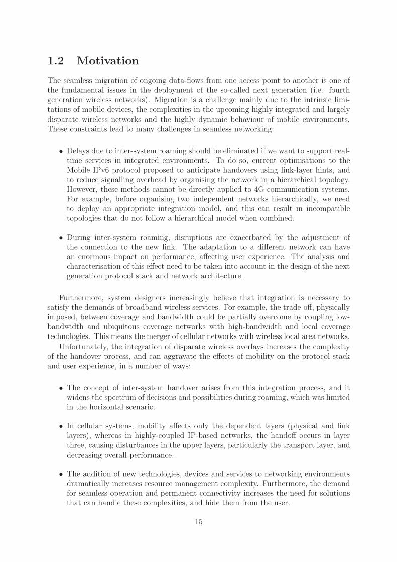
1.2 Motivation
The seamless migration of ongoing data-flows from one access point to another is one ofthe fundamental issues in the deployment of the so-called next generation (i.e. fourthgeneration wireless networks). Migration is a challenge mainly due to the intrinsic limi-tations of mobile devices, the complexities in the upcoming highly integrated and largelydisparate wireless networks and the highly dynamic behaviour of mobile environments.These constraints lead to many challenges in seamless networking:
• Delays due to inter-system roaming should be eliminated if we want to support real-time services in integrated environments. To do so, current optimisations to theMobile IPv6 protocol proposed to anticipate handovers using link-layer hints, andto reduce signalling overhead by organising the network in a hierarchical topology.However, these methods cannot be directly applied to 4G communication systems.For example, before organising two independent networks hierarchically, we needto deploy an appropriate integration model, and this can result in incompatibletopologies that do not follow a hierarchical model when combined.
• During inter-system roaming, disruptions are exacerbated by the adjustment ofthe connection to the new link. The adaptation to a different network can havean enormous impact on performance, affecting user experience. The analysis andcharacterisation of this effect need to be taken into account in the design of the nextgeneration protocol stack and network architecture.
Furthermore, system designers increasingly believe that integration is necessary tosatisfy the demands of broadband wireless services. For example, the trade-off, physicallyimposed, between coverage and bandwidth could be partially overcome by coupling low-bandwidth and ubiquitous coverage networks with high-bandwidth and local coveragetechnologies. This means the merger of cellular networks with wireless local area networks.
Unfortunately, the integration of disparate wireless overlays increases the complexityof the handover process, and can aggravate the effects of mobility on the protocol stackand user experience, in a number of ways:
• The concept of inter-system handover arises from this integration process, and itwidens the spectrum of decisions and possibilities during roaming, which was limitedin the horizontal scenario.
• In cellular systems, mobility affects only the dependent layers (physical and linklayers), whereas in highly-coupled IP-based networks, the handoff occurs in layerthree, causing disturbances in the upper layers, particularly the transport layer, anddecreasing overall performance.
• The addition of new technologies, devices and services to networking environmentsdramatically increases resource management complexity. Furthermore, the demandfor seamless operation and permanent connectivity increases the need for solutionsthat can handle these complexities, and hide them from the user.
15

There is a growing interest in practical mechanisms and solutions to facilitate seamlessmobility in upcoming 4G communication systems, formed by highly-coupled and hetero-geneous networks. By merging disparate wireless technologies it is hoped that users willenjoy ubiquitous access to plenty of services on the move. Unfortunately, the currentreality is that most proposals are complex, insufficient, and impractical. This dissertationaddresses this situation by presenting, deploying, and evaluating an integration architec-ture that facilitates seamless inter-system roaming. In addition, practical optimisationsand solutions are proposed to support mobility in these scenarios.
1.3 Contribution
It is my thesis that transparent migration of ongoing data flows between two accesspoints belonging to independent heterogeneous technologies is achievable, and that toolsand mechanisms for supporting this type of mobility should be placed within the nextgeneration networking architectures. Existing protocols do not cope with the impact ofheterogeneity on mobile networking—in this dissertation I describe the necessary mecha-nisms and tools, which together can offer a feasible solution and whose performance andpracticality can surpass current approaches.
• My first contribution is the design and deployment of an integration architecturethat enables vertical handovers between the most popular wireless and wired tech-nologies. Although many architectures have been discussed in previous work, themodel described in this thesis has been fully deployed into an experimental testbed.The main points that distinguish our testbed from other setups are that it evalu-ates MIPv6 in heterogeneous environments—other projects are constrained by thearchitecture itself—and we use Vodafone’s GSM/GPRS live network. As far as Iam aware, our testbed is the only one that enables a GSM/GPRS overlay using theactual provider’s network—previous projects emulate a GPRS link or install isolatedGPRS base stations (BSs), suffering from the absence of real operating conditionsduring the experiments.
• Another contribution is a suite of Mobile IPv6 optimisation mechanisms for differ-ent conditions in future networking environments. These are interesting not onlybecause of the reduction in handover latency, but also because they demonstratethat not every solution applied in horizontal scenarios works in the vertical caseas well. Performance results show that these modifications to the current MobileIPv6 specification can improve performance without affecting the core functionalityor adding significant overheads. Furthermore, the analysis of Mobile IPv6 perfor-mance in heterogeneous environments, coupled with my findings, represent a furthercontribution to the state of the art in mobility management.
16

• My last contribution is the design and implementation of a software solution toenable complete mobility support for nomadic users in 4G communication systems.By fully identifying the characteristics of next generation environments (e.g., het-erogeneity, high complexity, dynamic behaviour, and integration), it is possible todescribe the real challenges in supporting transparent mobility. Contrary to currentbelief, today’s solutions are not sufficient to assist mobile users in future networkingenvironments.
1.4 Outline of the rest of the dissertation
In Chapter 2 I briefly describe the evolution of computing systems, concentrating on themost relevant aspects from the perspective of this dissertation such as terminal mobilityand networking protocols. Then, I compare the main solutions to optimise roaming inhomogeneous and heterogeneous systems. Finally, I discuss the related work to policy-based systems in network management, and introduce the concepts of context awarenessand autonomic communications. A recurring issue is that enhanced terminal mobility isnow essential to enable the continued expansion of wireless services and networks.
In Chapter 3, I examine the integration of wireless networks into a ubiquitous accessplatform, and tackle some of the main challenges that this poses. A discussion of differentmerging strategies is included, deepened by the detailed comparison of the testbed withsimilar projects. I conclude the chapter with the design and deployment issues of theexperimental setup.
In Chapter 4, I present the performance analysis for MIPv6 during inter-system roaming,for which I used the testbed described in Chapter 3. In addition, I introduce the designand evaluation of four mechanisms to reduce latency: RA frequency, RA caching, BUsimulcasting, and soft handover.
In Chapter 5, I discuss the idea of applying autonomic computing principles linked withpolicy-based systems, to offer assistance for users in future communication environments.I explain the architecture, design, and implementation of PROTON 1, as an example ofsuch approach.
In Chapter 6, I explain how I tested my mobility assistance solution for correctness. Ithen present experimental results that demonstrate the practicality of my novel solution,its scalability in mobile environments, and the run-time performance. I close this chap-ter with a qualitative analysis of my solution compared to previous work. PROTON,together with the mechanisms covered in Chapter 4, can offer suitable roaming supportin 4G mobile systems.
Finally in Chapter 7, I conclude this dissertation, list the open issues stemming from thiswork, and suggest areas for further research.
1Policy-based system to ROam Transparently among Overlay Networks
17

18

Chapter 2
Mobility Management Overview
The advent of mobile computing implies the creation of novel communication architecturesand the modification of computer networks, operating systems, and applications [39].This chapter summarises previous work relating to mobility management and discussesthe limitations which place existing solutions beyond practical use in 4G communicationsystems.
In 1994, Randy H. Katz [49] stated that the next logical step in the natural evolutionof computing systems were Wireless Information Systems (Figure 2.1 shows an updatedtime-line based on Katz’s original). We can see that Katz’s vision was not far fromthe state of today’s technology. However, we are still far away from what the researchcommunity considers as ubiquitous networking.
The enhancements made in networking and computing capabilities in mobile devices,together with the deployment of wireless networks, has improved the nomadic computingexperience considerably. This revolution in the mobile world has extended users’ presenceby augmenting resource availability, increasing their productivity while travelling. Thesekind of facilities were not previously possible and now the pieces are in place to enableseamless terminal mobility, moving us one step closer to truly ubiquitous networking.
The remainder of this chapter is organised as follows. A brief introduction to mobilitymanagement protocols is included in Section 2.1. The challenge of terminal mobility isdescribed in Section 2.2, focusing on the problem of transparent roaming in 4G systems.Then, Section 2.2.1 outlines the basic Mobile IPv6 (MIPv6) functionality. Section 2.3presents protocols relating to terminal mobility and discusses why none of the proposedapproaches are viable for future heterogeneous roaming. Finally, Section 2.4 motivatesthe use of policy models for mobility management.
2.1 IPv6: Next generation Internet protocol
The Internet Protocol (IP) was developed in the early 1980s with the aim of supportingconnectivity within research networks, as part of Catenet [12]. However, in the lastdecade IP has become the leading network-layer protocol. It is the basic tool for a broadvariety of client/server and peer-to-peer networks; it predominates in both wired andwireless worlds, and now the current scale of deployment is straining many aspects ofits twenty five-year old design. To overcome the limitations inherent in the IP version4 design, IPv6 [27] has been proposed as the new protocol that will provide a firmer
19

Batch processes
Multi−user OS
NetworkingLANs + WANs
Terminal mobilityCode mobility
Mobile computing
Physical−space independence
Res
ourc
e sh
arin
g
Single user OS
Mainframes
Time sharing
Resource sharing
4G systemsNetwork mobility
Ubiquitous networking
Figure 2.1: The evolution of mobile computing.
base for the continued growth of today’s inter-networks. IPv6 was designed to improveIPv4’s scalability, security, ease-of-configuration, and network management; these issuesare central to the competitiveness and performance of network-related processes [52].IPv6 was devised to enable high-performance scalable inter-networks in the fixed world.Moreover, when IPv4 was conceived, the wireless world was not even close to what it istoday, thus IPv6 proposes solutions for some major IPv4 gaps in the support of mobility.
In forthcoming years, more people will access the Internet via wireless than via wiredconnections, and each user will have a set of wireless devices inter-connected that willbe accessing a great variety of IP-based services. Currently, there are approximately 1billion mobile phones in the world, and this number is expected to continue its exponentialgrowth in the next few years. In light of this, IPv4 faces many problems related to itsaddressing and mobility capabilities when considered in the context of the mobile world.Current extensions to the protocol tackle these problems. However, IPv6 contemplatesthem within its design, enabling a more robust solution.
The Internet has experienced enormous change in recent years, and the number ofusers accessing services on the move has also grown exponentially. Every mobile deviceis potentially capable of accessing IP services, Wi-Fi networks are becoming wide-spread;the spurt in the hotspot market is being accompanied by similar growth in other wirelesstechnologies such as Bluetooth, UltraWideband, and satellite, posing the urgent need fora larger address space and an adequate support for mobility.
The life of IPv4 has been extended via a technology called Network Address Transla-tion (NAT)—a mechanism that conserves scarce IPv4 addresses. Essentially, NAT allowsenterprises to deploy potentially large networks using shared IP-addressing space, andtranslating their Internet-bound traffic at their network edge to unique addresses as-signed to their enterprise. In this way, an enterprise can deploy a thousand computersystems and only consume a handful of unique IP-addresses.
20
FAHA FA
HAFA
x
1974 200420021998
IPv4 was designed to
2006
terminal mobilityMIPv4 enables
MIPv6 improves terminal
environmentsmobility in homogeneous
Mobility in 4G systemsC
ompl
exity
Time
new networking complexities
interconnect LANs
PAN P2P
WLAN
LAN
IPv6 responds to
Figure 2.2: Networking evolution and driver protocols.
Thus, NAT is effective in the way it allows more nodes to join the network than wouldbe possible if all nodes required routable addresses. This capability comes at a cost—thatcost is the loss of key functionality. As the Internet develops, more advanced applicationswill require end-to-end connectivity throughout the network–just the capability that isnot provided to NAT-enabled nodes. Additionally, many of these applications will requireextensive changes to facilitate operations through NAT, creating technically complicatedarchitectures. One last additional drawback for NATs is related to scalability constraints.The shared IP-address needs to be converted to a valid IP-address in every outgoing andincoming packet, which represents a huge constraint in large-scale networks.
Whereas the main thrust of IPv6 is to increase the address space and overcome NAT’sdrawbacks, it also provides important functions to enable mobility (e.g., scaling and ease-of-configuration) mainly derived from the larger address space. IPv4 has difficulties man-aging mobile terminals for several reasons such as address configuration and locationmanagement.
To drive the evolution in the mobile world, Mobile IPv6 [48] was proposed as a protocolthat exploits the added features in IPv6 to extend it and enable micro-mobility (roamingbetween access points within the same network domain) and macro-mobility (roaming toaccess points outside the current domain). With the introduction of IPv6, many of thedisadvantages of the previous version of mobility support (i.e. Mobile IPv4 [75]) wereeliminated. However, for Mobile IPv4 and Mobile IPv6 supporting seamless roaming inheterogeneous environments is outside the requirements.
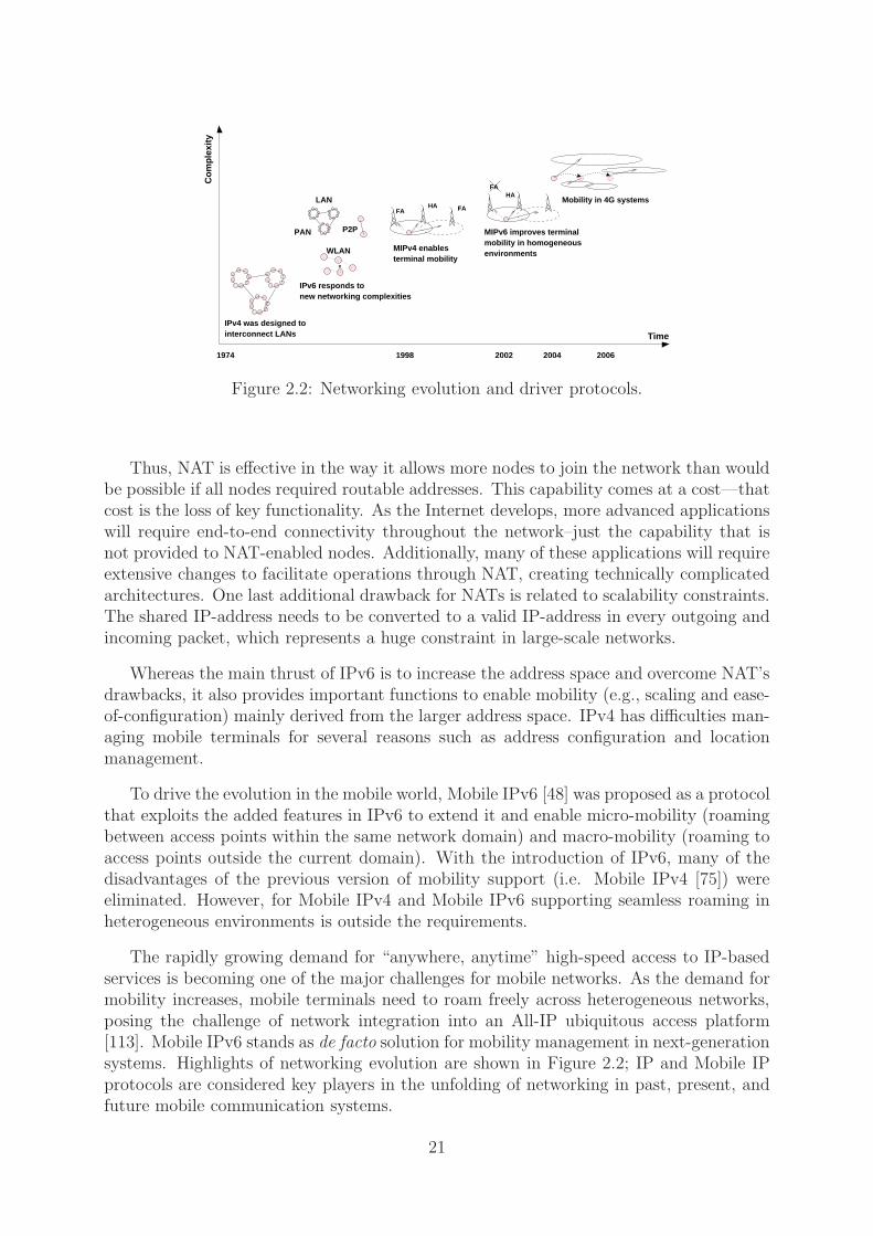
The rapidly growing demand for “anywhere, anytime” high-speed access to IP-basedservices is becoming one of the major challenges for mobile networks. As the demand formobility increases, mobile terminals need to roam freely across heterogeneous networks,posing the challenge of network integration into an All-IP ubiquitous access platform[113]. Mobile IPv6 stands as de facto solution for mobility management in next-generationsystems. Highlights of networking evolution are shown in Figure 2.2; IP and Mobile IPprotocols are considered key players in the unfolding of networking in past, present, andfuture mobile communication systems.
21

Figure 2.3: Basic Mobile IPv6 case example.
2.2 Terminal mobility
IPv4/v6 addressing and routing schemes entail that a host address relates to the point atwhich the host is connected to the network. This is exactly the opposite of what is neededfor mobility, because a mobile node frequently changes its attachment point and thereforeits address configuration. In fact, the TCP/IP network architecture has an imperfectlayered structure, in which the transport layer not only uses source and destination TCPport numbers (ports are the network abstraction at the TCP layer) but also the sourceand destination IP addresses as the connection identifier. This leads to a bad use of theIP address where it has dual functionality: (1) to identify connections above the networklayer and (2) to determine the packet’s routing. Thus, the host needs to have a stableaddress to identify ongoing connections and it should acquire a routable address from thenetwork to which it is currently connected.
Although during the last decade protocols for dynamic IP address assignment—forexample, DHCP [30]—have been designed, these solutions only provide portability and nottransparent mobility to roaming nodes. Portability is the terminal mobility capability thatallows a host to change its location. However the terminal is required to stop and restartits upper layer connections (e.g., TCP flows). In contrast, transparent mobility allows aterminal to move between different networks without dropping any ongoing connection.IPv6 provides portability because of its mechanisms for automatic address configuration,but not transparent mobility. MIPv4 and MIPv6 are the protocols defined to providesupport for reachability and transparent mobility in future All-IP networks.
The problem of mobility management in IP-based networks is twofold. The problem ofmanaging relationships between home addresses and care-of addresses, and the problemof using the appropriate type of address in relation to the context.
2.2.1 Mobile IPv6: How does it work?
Figure 2.3 shows the basic MIPv6 functionality as described in the IETF RFC at the timeof writing. Mobile IPv6 defines mechanisms that allow a terminal to change its point ofattachment to the Internet, and remain reachable through a permanent address whilstpreserving its active connections when travelling to its new location.
22

While a Mobile Node (MN) is connected to its Home Network (HN), i.e. the networkwhere its Home Address (HoA) is located, no special mode of operation is needed andpackets are forwarded (using normal IP routing) between the mobile node and any othernode it is communicating with (the correspondent node).
When a MN is connected to a network other than its home network, the MN acquiresan IPv6 address belonging to the address space of the Foreign Network (FN)—calledthe Care-of Address (CoA). The MN announces its CoA by sending a Binding Updatemessage (BU) to an special entity knows as the Home Agent (HA) that is located in theMN’s home network. This special router, the home agent, acts on behalf of the MN inits absence and usually serves all mobile nodes in a home network. The HA traces all theMN’s movements, maintaining the mapping between HoA and CoAs using BUs sent bythe nodes. This is known as the binding cache.
The HA intercepts the packets sent to the MN’s home address while the MN is awayfrom its home network and establishes a bidirectional tunnel terminating at the MN’sCoA. This tunnel is used to redirect intercepted packets to any MN’s current location.The MN also uses this tunnel to send its traffic to the Correspondent Nodes (CN), thusavoiding ingress filtering.
Furthermore, MIPv6 also defines a Route Optimisation (RO) procedure to avoid thesuboptimal routing problem caused by the use of bidirectional tunnelling through the HA.This procedure enables the MN to also send binding updates to the CNs. Packets sent bythe MN then have the MN’s CoA as source address, but also carry a special IPv6 homeaddress destination option, containing the MN’s home address, allowing a CN to use thisaddress as the source address when delivering the received packets to its upper layers (i.e.mobility is transparent to the layers above IP). In the reverse direction, the CN sendsthe packets addressed to the MN’s CoA, but also inserts a routing header Type II (seeSection 15.9 of [48]) with the MN’s HoA as a unique next hop. In this way, the MN canalso manage mobility in a transparent way with respect to those layers above IP.
Hence, we can see that Mobile IPv6 is suitable for providing support for roamingbetween networks and that it can be used from an Ethernet network to a wireless network,between homogeneous networks and, of more relevance to this work, between diverseaccess technologies.
Nevertheless, note that Mobile IPv6 has been conceived to support macro-mobilityand it is less suitable for micro-mobility. This dissertation includes the analysis of MIPv6to support macro-mobility in 4G systems, in which MNs will normally roam betweendisparate wireless technologies to obtain ubiquitous connectivity. Issues related to MIPv6performance and potential optimisations are discussed in chapters 3 and 4.
2.3 Terminal mobility protocols
Many projects have proposed schemes to support host mobility. These solutions can beclassified into micro-mobility and macro-mobility according to the type of roaming thatthey support. When a MN executes a vertical handover it usually changes its domain,and appropriate macro-mobility support is required. In this Section, popular schemes formicro- and macro-mobility are contrasted using the features listed in Table 2.1.
Unlike traditional link layer handovers (e.g., those in cellular networks) vertical han-dovers take place in different layers according to the level of integration between the
23

different access technologies (see Section 3.1.3). Thus, vertical handovers can occur atthe network layer, like Mobile IP, or even at higher layers, e.g., using TCP Migrate [86]or SIP [106]. Moreover, there are significant differences between the solutions dependingon where the handover occurs.
The aim of any mobility support scheme is to provide optimised and efficient roaming inevery possible scenario. Unfortunately, this may not always be possible. Even some link-layer handover latencies can still be very high, as much as 1000 ms in GSM, if handoverdecision and execution timeshare are included [96], and latencies increase when dealingwith inter-domain or network-layer handovers. Most communication systems can exploitdomain coverage overlap to reduce handover latencies by employing a “make-before-break”soft handover approach. To further minimise handover latencies, access networks are alsoorganised hierarchically to decrease update latency and localise signalling overhead. Thisresults in handover latencies generally suitable for voice traffic.
Transparent host mobility across heterogeneous networks demands a universal, physical-layer independent host mobility solution at the network layer or higher. Most commonapproaches are aimed at reducing handover latency, signalling load, and improving scal-ability and robustness.
Table 2.1 compares several schemes, each of them with particular advantages for hostmobility. These solutions do not always preclude the simultaneous usage of others listed inthe table; instead, they may complement each other to offer improved performance. Forexample, the Intra-Domain Mobility Management Protocol (IDMP) leverages existingmacro-mobility management protocols, such as Mobile IP and SIP [106], for locatingroaming nodes.
Table 2.1 includes a set of characteristics that are relevant for both micro- and macro-mobility. These aspects are defined below:
• Handover latency: To improve user experience, it is important to maintain han-dover latency as low as possible.
• Mobility: It is difficult to define what is high and low mobility. However, in thecontext of this work high mobility means the capability to cope with more than10 handovers per minute. In contrast, a host performing less than 10 handovers isconsidered to have low mobility.
• Low signalling: In order to reduce latency, it is important to maintain low sig-nalling and decrease the use of bandwidth for sending control or management data.
• Real time: This characteristic evaluates the capability of the solution to reducedelays caused by host mobility and achieve acceptable values for real time applica-tions.
• QoS support and AAA support: Another requirement for a complete solution isto offer QoS and AAA support during roaming. Most of the mobility managementprotocols keep functionalities separated to avoid complexities.
• Scalable: This property evaluates if there is some part of the solution that affectsits scalability e.g., signalling, delays, etc.
24

Micro-mobility Macro-mobilitySolutions IDMP CellularIP HAWAII SIP TeleMIP S-MIP TCP MigrateLow handover latency
√ √ √×
√ √×
High mobility√ √ √
× ×√
×Low signalling
√ √ √ √ √ √ √
Real-time ×√ √ √
× × ×QoS support × ×
√ √× × ×
Scalable√ √ √ √ √ √ √
AAA support × × × × × × ×MIPv6 compatible
√ √ √ √ √ √ √
Optimisations√ √ √ √ √ √ √
Global mobility × × ×√ √ √ √
Table 2.1: Host mobility support.
• MIPv6 compatible: Compatibility with MIPv6 is considered because it is de factostandard in industry and academia. Table 2.1 indicates if the solution is compatibleor not with MIPv6.
• Optimisations: There are some well defined methods to optimise mobility manage-ment. This property indicates if any of them are used in the solution e.g., HMIPv6,L2-hints, etc.
• Global mobility: It is also shown if the protocol supports global roaming (micro-and macro- mobility), or if it needs other solutions to handle complete mobility.
2.3.1 Micro-mobility solutions
IDMP [25, 67] is a standalone approach that provides a multiple CoA intra-domain mobil-ity solution, and is one of the several IP-based hierarchical mobility management solutionsthat attempts to minimise handover latency. But unlike micro-mobility solutions likeHAWAII or Cellular-IP, it can be made to work, completely independently, with MobileIP for enabling global host mobility.
IDMP can enhance Mobile IP in micro-mobility environments with high handoverfrequency (more than 1 handover per second) and also could decrease signalling load ina global solution. Furthermore, it can offer paging services to locate mobile nodes withina particular domain and save power, an important consideration for next generation’sresource-limited or constrained devices.
However, the protocol is not enough to manage mobility in 4G communication systemsbecause it cannot offer macro-mobility support by itself, despite the fact that it optimisesintra-domain roaming. Heterogeneous roaming demands a global solution such as Mo-bile IP, but one that is optimised to perform well in inter- and intra- domain roaming.IDMP originally was deployed using the Linux Mobile IP code of the Standford UniversityMosquito Project that did not study vertical roaming [55].
Similar approaches have used methods originally applied to cellular systems to optimisenetwork-level handovers. Micro-mobility protocols such as Cellular IP [11] and HAWAII[80] optimise handover latency and reduce signalling load by distinguishing between themovement of the MN within the domain and outside the domain (i.e. hierarchical han-dovers). Also, other optimisations are based on the availability of cross-layer information,particularly from the link layer, to anticipate handovers, so called “fast handovers”.
25

The CellularIP protocol [10] from Columbia University and Ericsson Research supportspaging and a number of handover techniques and optimisations. To minimise signalling,regular packets are sent to update host location information. CellularIP avoids paging tominimise signalling and reduce power consumption. However, CellularIP is also limitedto supporting heterogeneous roaming between different domains, and relying on someinter-domain mobility management protocol to support global mobility, such as MobileIP.
HAWAII, from Lucent Technologies, proposes a separate routing protocol for micro-mobility. HAWAII [80] relies on Mobile IP for inter-domain roaming. One importantaspect is that HAWAII is not a standalone solution, it extends Mobile IP to provideintra-domain mobility with QoS support. When Mobile IP is used for micro-mobility, itresults in high control overhead due to the frequent notifications sent to the home agent,and high latency causing disruptions during handover. Also, in the case of a QoS-enabledhost, acquiring a new care-of address on every handover would trigger the establishmentof new QoS reservations along the complete path to the CN, even when the majority of itremains unchanged. HAWAII leverages Mobile IP to enable QoS-aware micro-mobility.
2.3.2 Macro-mobility solutions
To overcome the limitation of global mobility, TeleMIP [26] combines IDMP and Mo-bile IP for intra-domain and inter-domain mobility support respectively, to provide anattractive and scalable mobility management solution for All-IP networks. Although hi-erarchical extensions to Mobile IP clearly optimise high-frequency updates, TeleMIP’sauthors argue that introducing multiple levels of hierarchy in a commercial multi-levelprovider environment can often lead to network management and security issues. Insteadof having a multi-level hierarchy, TeleMIP attempts to achieve a balance between theproblems of high update latency and complex management architectures by introducingan structure that makes use of only a two-level hierarchy.
Despite the fact that TeleMIP improves Mobile IP performance in the intra-domainscenario, it does not modify MIP for inter-domain roaming. This aspect makes TeleMIPunsuitable for heterogeneous environments where roaming between different domains is avery common situation.
S-MIP (Seamless Handoff architecture for Mobile IP) differs from previous schemesbecause it combines the advantages of both fast handovers [53] and hierarchical mobilityschemes [88] to enable what it calls “smarter” handovers. It introduces the conceptof Synchronised Packet-based Simulcast (SPS) by simulcasting packets to the currentand new networks, thus minimising packet loss during handovers. S-MIP [43] builds onthe structure of Hierarchical Mobile IPv6 (HMIPv6) with fast handovers and operatessimilarly to the Mobile Node Initiated Fast handover scheme [53]. Unlike the HMIPv6with fast-handover approach that uses layer-two triggers, in S-MIP the network usesthe MN’s location and movement patterns to instruct the MN when to handoff. S-MIPuses physical context data to enable context-aware handovers in a similar manner as themobility support solution presented in Chapter 5. In [42] the authors present a simulationof S-MIP that compares it with plain HMIPv6 and fast handovers for homogeneous micro-and macro-mobility. Similarly, this work evaluates MIPv6 during vertical handovers usingan experimental testbed that emulates a 4G system.
26
At the time of writing, apart from MIPv4/MIPv6, the IETF proposes two main so-lutions to manage mobility: Hierarchical MIPv6 and a Fast Handover Protocol. Eventhough MIPv6 offers several benefits, the signalling overhead’s effect on the network loadcan at times be significant and the handover process can be long. Hierarchical MIPv6focuses on local movements to reduce the signalling load on the network. The idea behindHMIPv6 is to divide the global Internet into logical regions defining domains that are in-dependent from subnets. This mitigates the signalling load on the network. On the otherhand, the Fast Handover Protocol, also an extension to MIPv6, allows access routers tooffer services to the MN in order to anticipate handovers. The movement anticipationof the MN is typically based on layer-two (L2-level) triggers. These two optimisationswill be discussed further in Section 4.1. An IETF working group, called Seamoby [50],is considering the complex interaction of parameters and protocols needed for seamlesshandover. The two main issues dealt with at the time of writing in Seamoby are thedormant mode host alerting problem (i.e. paging) and context transfers between nodesin an IP access network.
TCP Migrate [86, 87] provides a way of achieving session-layer host mobility. Here,TCP is modified on both the mobile and correspondent nodes such that it can with-stand changes in IP address during a connection. Using DNS, the correspondent nodelearns the current address of the MN, with the DNS being updated every time the hostmoves. However, TCP Migrate lacks support for location privacy, and cannot have twomobile nodes communicating simultaneously, making it suitable only for client-server typeof applications (e.g., email, web downloads, etc.) and not appropriate for peer-to-peertopologies.
Finally, SIP [106] supports higher-layer (application-level) host mobility. SIP exploitsknowledge about the traffic at a higher layer to benefit real-time flows. This scheme isquite similar to MIPv6 (or MIP with route optimisations) and is especially advantageousfor real-time traffic, both voice and video, as it reduces end-to-end latency by allowing aCN to directly communicate with the mobile node’s CoA, without needing direct traffictunnelling through the home agent.
In conclusion, many solutions have been proposed to solve transparent mobility. Theperfect protocol does not exist; trade offs between overhead and performance are alwayspresent (see Table 2.1). Mobile IPv6 has become the standard for industry and academia,but its deployment in 4G systems poses performance issues that need to be addressed.A wide body of research in mobility has resulted in a number of approaches to optimiseMobile IPv6. Chapters 3 and 4 discuss practical mechanisms proposed to tackle thischallenging issue.
2.4 Policy models to enable seamless mobility
Networking complexities in future multi-homed devices equipped with several interfaces,which may belong to different access technologies, and upcoming 4G systems pose theneed for assistance during roaming. Currently, few solutions propose any means for theuser or application to be able to dynamically influence the roaming process (networkselection, handover initiation, execution, etc.) However, in forthcoming communicationsystems, tools to control network roaming will be essential.
27

There has been considerable effort dedicated to developing policy models to controldata storage [85], quality of service [108, 36], and system security [89, 29]. There aremodels to influence the behaviour of mobile components [17, 18] for adapting them toevolving system conditions. Of relevance to this work, policies are being used in mobileenvironments [40] to provide means of specifying the adaptive behaviour in networks anddevices [84], and to enable seamless mobility in future ubiquitous environments [101].
Chapter 5 describes a policy-based system, PROTON, that provides mobility manage-ment support in 4G systems. To the best of the author’s knowledge, the proposed model isthe first that addresses mobility assistance in such a fashion [100]. Other projects exploitadvantages offered by policies to tackle mobility management, yet there are meaningfuldifferences that are shown in the qualitative evaluation included in Chapter 6—in whichPROTON is extensively contrasted with other approaches.
Many important issues related to mobility management have already been addressedusing policy models, however, a general solution has not yet been implemented. Most ofthe work done focuses on particular problems, mainly due to the complexity implicit inoffering complete mobility support—it can be beyond mobile devices’ capabilities.
One of the problems that was encountered when the concept of overlay networks wasfirst proposed at UC Berkeley, was controlling handovers between independent networks.In [104] this problem was first addressed, the proposed handover mechanism being basedon simple decision policies according to cost functions, and it was limited to the selectionof the best access network. The authors mentioned that offering full assistance wouldresult in an excessive increase in complexity; for this reason, it is argued in this workthat it would be better to use simple policies, instead of cost functions, as they are moreflexible and have lower computation overhead. They alluded to the possibility of theinclusion of more parameters in the policy model to enrich the decision-making process.
Further projects followed this work and developed other approaches such as fuzzy logicalgorithms [14] and more comprehensive policy models. Some of these solutions utilisedcomplex decision-making tools—neural networks or fuzzifiers—that are disadvantageousfor the dynamics of mobile environments. In the handover process the basic problem isnot to find the “best” solution, but a fast and convenient decision. Multi-homed deviceswere enhanced with interface selection mechanisms supported by policies [112].
These mechanisms allowed dynamic decision-making during the operation of the mo-bile device. However, initial approaches were unable to use more than one network in-terface simultaneously. More recent solutions for policy-based routing enabled mobiledevices to utilise all active network interfaces and provided optimum interface selection.Most of them were based on Mobile IPv4/v6.
Wakikawa et al. [103] proposed modifications to Mobile IPv6 to enable the use ofmultiple network interfaces. They managed to enhance the protocol, but not to enablea seamless handover process due to the latency of switching interfaces (this fundamentalobstacle is tackled in Section 4.1) and in the TCP congestion control algorithm owing topacket losses (discussed in Section 4.5.4).
Mobile devices began to proliferate and wireless networks became insufficient for thenumber of users per access point. Smart network selection began to be useless without asupporting access architecture. Therefore, the use of policy models to enable intelligentaccess [71], admission control, and mobility management were explored.
28

After solving the basic problem of handover management, research moved towardsseamless mobility. At the same time, emerging protocols such as Mobile IPv4 and MobileIPv6 triggered the design of new solutions. The use of signal strength information—usually related to link-layer handoffs—to enhance network-layer Mobile IP handovers wasproposed and successful mechanisms were developed. In [4] the authors proposed the use oflink-layer hints to improve networking, posing the idea of cross-layer data exchange. Theconcept of designing data-aware handover mechanisms is taken further in this dissertationwith PROTON that uses a rich dataset (Networking Context), which includes data fromevery layer, from the user, and from the physical environment.
Policy-based handover initiation methods [13] reduce the effect of mobility on perfor-mance, permitting the support of a greater number of mobile services. A new wave ofhorizontal handover mechanisms facilitated the deployment of mobile real-time applica-tions, by providing transparent mobility between two hotspots [9].
Patanapongpibul and Mapp [74] suggested caching incoming RAs from every potentialaccess point, and controlling the cache with some sort of replacement criterion to ensureRA validity. This method reduces horizontal handover latency by avoiding network dis-covery delays. They claimed a latency reduction from approximately 2200 ms to 250 ms(without packet loss) for TCP flows.
At this point, a problem emerged as a consequence of the broad variety of mobiledevices, wireless technologies, and services. Heterogeneity became the problem tackledby another generation of policy-based solutions. Decision-making happens to be morecomplex in these environments, and as a response novel context-aware policy modelsarose.
Context knowledge was essential to improve networking performance. Connectivityshowed high dependencies on surrounding conditions and many networking tasks becamecontext-dependent. Limiting decision-making to the received signal strength was no longerpossible. Context-aware solutions were developed and supported by policy-based archi-tectures, strongly motivating the creation of policy models to handle the complexitiesposed by pervasive interaction in heterogeneous systems.
In [47] a network-oriented methodology to offer context-aware services is presented.This European project (CONTEXT) proposes a scenario where context information iscollected by the network, and used to provide context-aware services to mobile clients.Thus, when MNs connect to the CONTEXT-based network, they receive the “best pos-sible” QoS based on current network context.
Making use of this momentum, PROTON proposes a formal policy representationthat allows MN’s to react to context data. It can be seen as a collection of context-triggered actions adapted to hostile mobile environments. PROTON provides assistancefor wireless worlds, in which devices are exposed to unpredictably changing contexts,such as unreliable connectivity conditions, by actively or passively migrating through oneenvironment or between multiple environments. This together with the heterogeneityin access networks increases the number of parameters to be considered when reasoningabout networking resources.
Context awareness increases autonomy in systems and represents a good way to hideunnecessary complexities from users. A context-aware system is one in which applicationshave knowledge of their surrounding physical and computing environments. This knowl-edge can be applied to minimise user participation by the definition of the governing rules
29
between networking resources and user activities in 4G systems. The research communityrecognises the general issue of complexity as the crucial inhibiting factor of technologicaladvancement and proposes context-aware policy models as a holistic solution. However,complexities posed by forthcoming 4G systems can go beyond the capabilities of policy-based solutions forcing a new evolution.
In its visionary manifesto IBM, anticipating the need for more autonomous solutions,expands the frontiers of policy models. Foreseeing the insufficiency of current models, itoutlines the concept of autonomic computing [44]. By deploying novel autonomic solu-tions, the following issues could be addressed: reducing networking complexity, copingwith proliferation of wireless access technologies and networking paradigms, supportingmobility, providing personalised services, and adaptive computing, and improving per-formance and efficiency. Constraints and challenges in mobile environments need to bestudied and novel solutions proposed before taking further steps towards seamless mobil-ity.
30

Chapter 3
The LCE-CL Experimental Setup
We are witnessing the development and deployment of a large number of wireless net-working technologies including 3G, WLANs, Bluetooth, and UltraWideband. At the sametime we are seeing a convergence of core networking infrastructure based on the InternetProtocol Suite (IP) [94]. IPv4 is widely deployed throughout the world and there is nowa serious effort to deploy IPv6, which simplifies mobility support.
There is a significant need for a unified approach that integrates all disparate wirelesstechnologies (see Table 3), and enables mobile users to seamlessly roam between networkswhile accessing applications with different service requirements. This convergence posesmany challenges, which need to be solved before the deployment of a real 4G system.
Vertical handovers are challenging for current transport protocols, because packetsmay get lost, disordered, or delayed during the handover and therefore affect performance.Moreover, methods to minimise latency during vertical handovers are needed to supportreal time applications in these future systems.
Network Coverage Data Rates Cost
Satellite World Max. 144 kb/s HighGSM/GPRS Aprox. 35 km 9.6 kb/s up to 144 kb/s HighIEEE 802.16a Aprox. 30 km Max. 70 Mb/s MediumIEEE 802.20 Aprox. 20 m 1-9 Mb/s HighUMTS 20 km up to 2 Mb/s HighHIPERLAN 2 70 up to 300 m 25 Mb/s LowIEEE 802.11a 50 up to 300 m 54 Mb/s LowIEEE 802.11b 50 up to 300 m 11 Mb/s LowBluetooth 10 m Max. 700 kb/s Low
Table 3.1: Diversity in existing and emerging wireless technologies.
In 2002, the Laboratory for Communication Engineering (LCE) and the ComputerLaboratory (CL) at the University of Cambridge came together to develop the LCE-CL testbed, which has been used to study the challenges related to the deployment offorthcoming mobile systems. This chapter presents the design, integration architecture,and deployment of the testbed. The goal is to build a platform that fully integratesheterogeneous wireless technologies, anticipating that in the near future mobile deviceswill have several wireless interfaces and users will expect connections to be seamlessly
31

TCP/UDP
NETWORK
LINK/PHY
TCP/UDP
NETWORK
LINK/PHY
WLAN 3G satelliteGPRSLAN
4G COMMUNICATION SYSTEM
WLAN 3G satelliteGPRSLAN
4G COMMUNICATION SYSTEM
INTERNETCORE NETWORK
INTEGRATION CORE LAYER
INTERNETCORE NETWORK
INTEGRATION CORE LAYER
INTERNETCORE NETWORK
WLAN 3G satelliteGPRSLAN
4G COMMUNICATION SYSTEM
NETWORK
LINK/PHY
NETWORK
LINK/PHY
INTEGRATION CORE LAYER
A. Tunneled Networks Model B. Hybrid Networks Model
LINK/PHYLINK/PHY
C. Heterogeneous Networks Model
Figure 3.1: Taxonomy according to the integration layer.
managed. In that sense, the testbed can be regarded as a prototype of a 4G system withparticular focus on mobility. Experimental activities play a vital role in the developmentand deployment of novel radio access networks. In particular the move from 3G to 4Gposes new challenges, which need to be solved using practical approaches such as testbeds.
The remainder of this chapter is structured as follows: Section 3.1 describes severalpossible integration techniques from the perspective of the OSI network model. The tech-niques used to build the testbed are described in a three-dimensional taxonomy. Section3.2 introduces the testbed, mentioning important aspects that are used to contrast it withsimilar work. Section 3.3 compares the LCE-CL testbed with previous projects, focusingon the aspects that make it unique and different from the others. Section 3.4 includesimportant hardware-related information for the deployment of the testbed. The relevantsoftware components are mentioned in Section 3.5. Finally, Section 3.6 closes the chaptersummarising the main objectives of the LCE-CL testbed.
3.1 Integration techniques
One of the main features of the 4G communication systems is the inter-operation of mul-tiple radio access technologies (RATs). Contrary to homogeneous environments, manyapproaches can be taken depending on the level of integration desired between differentRATs; the level of integration achieved is strongly correlated with the degree of modifica-tion required for each individual technology. This section places the LCE-CL testbed intoa three-dimensional taxonomy: (1) the OSI-model layer where the integration takes place,(2) the component that connects the disassociated technologies, and (3) the common andindependent functionality in the architecture.
32

3.1.1 OSI-layer integration
There are several architectures using multiple RATs. The basic models—considering theintegration layer—are shown in Figure 3.1 [109]. The LCE-CL testbed integrates disparateaccess networks using a core IP-layer to manage networking (i.e. a heterogeneous networksmodel).
• Tunnelled Networks: Upper layers access the different technologies indepen-dently. According to policies, the best network is selected and the integration layertunnels the traffic across the Internet and the chosen RAT. Thus, no modificationsare required to the existing network stacks. However, service latency increases,mainly because of duplication and lack of integration in the lower layers.
• Hybrid Networks: In this model, the individual RATs implement the three lowestlayers (Physical, Link, and Network layers). There is a hybrid core that interfacesbetween the Internet and the different wireless access networks. The main drawbackof this model is that networking activities are duplicated, however, the stack doesnot need to be modified. Nevertheless, the service latency reduces because there isnot as much redundancy in functionality as in tunnelled networks.
• Heterogeneous Networks: In this model there is a core layer that deals with allthe network functionality and operates as a single network with respect to the upperlayers. Thus, different RATs implement only the physical and link layers, which arespecifically related to each technology. A major obstacle of this model is that thedifferent access networks must converge, which requires a huge standardisation effortand operator commitment.
Nevertheless, heterogeneous networks are a promising solution for 4G systems. Usinga module-based design to minimise impact on the networking stack, current protocols canbe changed to include Mobile IP and thereby provide the required level of integration.
3.1.2 Networking-component integration
Inter-networking between wireless technologies was considered by the 3GPP TSG [1] work-ing group. This group drafted a feasibility study in which they presented four levels ofintegration between RATs, according to the component where coupling takes place [2].The main integration scenarios are shown in Figure 3.2 and listed below.
• Open Coupling: There is no real integration effort between two or more accesstechnologies. Thus, separated sub-processes take place, however the billing systemis shared between networks. These models do not enable seamless inter-technologyhandovers. When the terminal changes its current access router to another, theongoing session is terminated.
33

AR access network
Base station
RNCInternet
SGSNGGSN
CGSNGPRS edge router
AB
CInter−networking
unit
edge router
Tight CouplingLoose CouplingOpen Coupling
Figure 3.2: Integration Models: Depending on the integration components.
• Loose Coupling: Defined as the utilisation of a generic RAT (e.g., WLAN) as anaccess network complementary to current 3G access networks. It uses a commonsubscriber database without any user plane Iu interface1, i.e. avoiding the SGSNand GGSN nodes. Thus, the RATs are integrated in the network layer by addingspecial purpose inter-networking components.
• Tight Coupling: The key characteristic of this model is that the generic access net-works (e.g., WLAN) are connected to the core network (e.g., GSM/GPRS) sharingthe Iu interfaces. Thus, the level of integration impacts the core components—theGGSN and SGSN in the case of Vodafone’s GPRS architecture. This enables theintegration of most of the operational capabilities into a single platform. There isone more type of integration considering the components that need to be modified.Networks can also be fully integrated, meaning that the integration affects corecomponents in both, core and access networks.
Broadly speaking, integration architectures have been classified into loose coupling andtight coupling, as the main difference among them is the ability to offer service continuity2.
3.1.3 OSI-functionality integration
There are other reasons to have the integration built into the network layer or above. TheOSI model separates functionality into layers, lower ones are responsible for connectioncontrol and upper layers are in charge of presenting the data. The lower two layers (i.e.physical and link layers) are strongly attached to the specific access technology in use.Signalling and control for a specific technology happen between these two layers, whereasIP facilitates the integration of heterogeneous networks because it only includes controland signalling (e.g., addressing, routing, encapsulation of packets or datagrams) commonto every technology.
1The Iu interface provides connection between the Radio Network Controllers (RNCs) and certaincore nodes in the GPRS network
2Service Continuity is the capability to maintain services during the process of changing access networktechnology [2]
34

Thus, the OSI model can be split into two levels: (1) network-dependent functionsand (2) application-oriented functions. This means that an application can utilise anetwork without knowing how it operates or what protocols are used for transmission.The transport layer forms the interface between application-oriented services and network-dependent functions.
This means that network integration can be done in any layer apart from layers one andtwo without dealing with any technology particularities. However, the added overheaddue to this kind of integration above the network layer is enormous, as well as the impacton overall performance and user experience. Almost all the functionality is duplicated,including key networking services that are the bottleneck in data transmission (i.e. IP-layer functions).
In the OSI model, the next level of integration is the network layer. Although itis network-dependent, due to the explosive growth of TCP/IP-based applications andservices most of the technologies have converged on IP. Most of the current heterogeneousradio networks use different mappings of IP onto the data plane, and hide the signalling(e.g., connection control, handover, networking signalling, etc) from the network layer.
Thus, the IP layer does not include any signalling or network control functions, how-ever, there is nothing to prevent the inclusion of these kinds of functions in any layer.Nevertheless, in forthcoming 4G communication systems, composed of highly heteroge-neous integrated networks, the inclusion of additional functionality into the IP layer canhave a negative impact due to existing dependencies between the network layer and theradio technologies underneath, which can drastically increase complexities during the in-tegration process.
The same situation arises when discussing application-related services, e.g., Quality ofService mechanisms are specified for every technology (Integrated Services, DifferentiatedServices, Multiple Packet Label Switching, or best-effort mechanisms) and these are visibleto the layers above IP. This heterogeneity in QoS makes IP-layer integration difficult.Thus, mobility support approaches for 4G systems need to separate application- and data-related functions in order to offer a simple solution. In contrast, if these functionalities aremixed, either cross-layer interaction needs to be considered or QoS mechanisms shouldbe added to IP or MIP [15].
The LCE-CL testbed proposes a loose-coupled architecture that enables seamless mo-bility between heterogeneous environments by integrating the RATs using a common IPlayer (network layer). The testbed’s architecture clearly separates data and control func-tionality, but is presently limited in terms of offering QoS guarantees to mobile users.It enables service continuity between access and core networks without affecting corenetwork components or adding functional complexities.
3.2 The testbed
The testbed supports connectivity to the most relevant access networks: IEEE 802.3,IEEE 802.11a, and GSM/GPRS networks. The GPRS infrastructure comprises base sta-tions that are linked to the SGSN (Serving GPRS Support Node) which is then connectedto a GGSN (Gateway GPRS Support node). In the current Vodafone configuration, boththe SGSN and the GGSN are co-located in a single CGSN (Combined GPRS SupportNode). A well provisioned virtual private network (VPN) connects the Lab network
35

to that of the Vodafone’s backbone via an IPSec tunnel over the public Internet. Aseparate “operator-type” RADIUS server is provisioned to authenticate GPRS mobileusers/terminals and also assign IP addresses.
For access to the 4G integrated network, mobile nodes (e.g., laptops) connect to thelocal WLAN network and simultaneously to GPRS via a Phone/Card modem. The mobilenode’s MIPv6 implementation is based on that developed by the MediaPoli project [66],chosen for its completeness and open source nature. A semi-permanent IPv6 subnet fromBTExact’s IPv6 Network, connects the testbed to the 6BONE. Using this address space,it is possible to allocate static IPv6 addresses to all the IPv6 enabled mobile nodes. Arouter in the lab acts an IPv6/IPv4 tunnel end-point to BTExact’s IPv6 network. Thisrouter is also an IPv6 access router for the lab’s fixed-internal IPv6-enabled networkand for internal WLANs. Routing has been configured such that all GPRS/WLAN usertraffic going to and from mobile clients passes through the internal router, enabling trafficmonitoring.
Since the GPRS cellular network currently operates only on IPv4, A SIT (SimpleInternet Translation) tunnel forwards all IPv6 packets as IPv4 packets between the mobilenode and a machine providing IPv6-enabled access router functionality on behalf of theGPRS network. Ideally, the GGSN in the GPRS network would provide this functionalitydirectly, but using the tunnel causes only minor overhead, and it represents the currentstate in IPv4-to-IPv6 migration.
The testbed integrates several independent IP networks, including three IEEE 802.11bsub-networks, Vodafone’s GSM/GPRS network, and the Lab’s local area network. Thissetup was designed to do experimental analysis of intra-network and inter-network handovers—also known as horizontal and vertical handovers respectively.
The mobile node’s home agent provides network connectivity through an IEEE 802.11baccess point. Additionally, foreign networks (e.g., IEEE 802.11b sub-networks, GSM/GPRSVodafone’s network, M-DVB link, and Ethernet LAN) allow the mobile node to stay con-nected by the HA emitting router advertisements and providing secondary radio coverage.This experimental testbed enables the mobile node to perform seamless roaming betweenheterogeneous technologies, and maintain connectivity with its correspondent nodes.
3.3 Related work
Several testbeds have been proposed (and some of them implemented) that emulate 4Gsystems. Most of these environments provide limited mobility between heterogeneousnetworks based on existing mobility management protocols (e.g., MIPv4, MIPv6, andSIP). This section contrasts the LCE-CL testbed with previous projects. Firstly, themost relevant testbeds are described. Then, the functionality needed to evaluate a 4Gsystem is mentioned. Finally, fundamental differences with previous work are highlighted.
The following projects represent a short-list of the most relevant testbeds deployedover the years. The main work done on the correspondent testbeds is summarised below.
36

• BARWAN testbed: The concepts of wireless overlay networks and vertical han-dover were introduced in 1996, as part of the BARWAN project at Berkeley [49, 90].The first overlay networks testbed, the BARWAN testbed, included WaveLAN, In-frared, and Ricochet wireless networks. This testbed was based on MIPv4 and wasa pioneering work in the area of mobile networking.
• MosquitoNet testbed: Other researchers proposed many testbeds and simula-tions [8, 111], concentrating on the evaluation of MIPv4 during intra-technologyhandovers. MosquitoNet was one of these testbeds, deployed at Stanford University[55]. Later on, with the growth of IPv6 and the deployment of MIPv6, a new gener-ation of testbeds appeared. MosquitoNet continued working on minimising delaysduring horizontal handovers and later on started evaluating MIPv6 performance inheterogeneous environments.
• EURESCOM testbed: In 2002, EURESCOM [33] funded an European testbed[35, 34] to evaluate the use of Mobile IP in an All-IP core network. At the end of thisproject [83], they implemented a MIPv4-based testbed that integrated GPRS, LAN,and WLAN as sample technologies, and they evaluated MIPv4 and Cellular IP asmobility management protocols. However, this project focused on recommendationsand did not consider practical results related to handover issues in detail.
• Moby Dick testbed: MIPv6-based testbeds have been used to study the integra-tion of different radio access technologies into one IP-based core infrastructure. Arecent example, Moby Dick [22, 59], proposed and implemented a global end-to-endMIPv6-based architecture to offer QoS in heterogeneous environments. The testbedincluded UMTS-like TD-CDMA wireless access technology, IEEE 802.11b WLANs,and wired connectivity. Further work is being done as part of a new initiative:Daidalos project [23].
• Nomad testbed: The Nomad project [73] terminated in June 2004 [76], after suc-cessfully setting up and measuring a MIPv4-based testbed [54, 37]. They evaluatedseamless roaming between heterogeneous networks based on MIPv4.
• MIND testbed: MIND [65] is the follow up of the IST project BRAIN (Broad-band Radio Access for IP based Networks). These two projects implemented anexperimental setup, which integrated IEEE 802.11b, UMTS TDD, and GPRS. Theyevaluated MIPv6 during inter- and intra-technology handovers [64, 82].
These testbeds have produced very interesting results for the improvement of mobilitymanagement and wireless networking. However, they present limitations compare to theLCE-CL testbed. The general features of a good testbed to study 4G systems are:
• Flexibility for the adherence of access technologies and modification of core net-working components and software.
• A good level of integration to support seamless mobility without incurring overheadin process duplication.
• Inclusion of real networking conditions to increase accuracy in the experimentalresults.
37
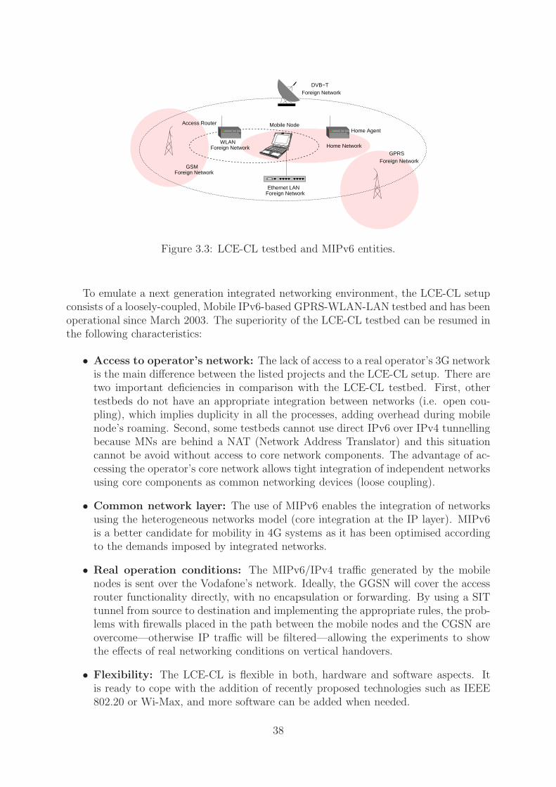
Home Network
Ethernet LAN
Foreign Network
Foreign Network
Foreign NetworkDVB−T
GSM
GPRS
WLANForeign Network
Foreign Network
Home AgentMobile NodeAccess Router
Figure 3.3: LCE-CL testbed and MIPv6 entities.
To emulate a next generation integrated networking environment, the LCE-CL setupconsists of a loosely-coupled, Mobile IPv6-based GPRS-WLAN-LAN testbed and has beenoperational since March 2003. The superiority of the LCE-CL testbed can be resumed inthe following characteristics:
• Access to operator’s network: The lack of access to a real operator’s 3G networkis the main difference between the listed projects and the LCE-CL setup. There aretwo important deficiencies in comparison with the LCE-CL testbed. First, othertestbeds do not have an appropriate integration between networks (i.e. open cou-pling), which implies duplicity in all the processes, adding overhead during mobilenode’s roaming. Second, some testbeds cannot use direct IPv6 over IPv4 tunnellingbecause MNs are behind a NAT (Network Address Translator) and this situationcannot be avoid without access to core network components. The advantage of ac-cessing the operator’s core network allows tight integration of independent networksusing core components as common networking devices (loose coupling).
• Common network layer: The use of MIPv6 enables the integration of networksusing the heterogeneous networks model (core integration at the IP layer). MIPv6is a better candidate for mobility in 4G systems as it has been optimised accordingto the demands imposed by integrated networks.
• Real operation conditions: The MIPv6/IPv4 traffic generated by the mobilenodes is sent over the Vodafone’s network. Ideally, the GGSN will cover the accessrouter functionality directly, with no encapsulation or forwarding. By using a SITtunnel from source to destination and implementing the appropriate rules, the prob-lems with firewalls placed in the path between the mobile nodes and the CGSN areovercome—otherwise IP traffic will be filtered—allowing the experiments to showthe effects of real networking conditions on vertical handovers.
• Flexibility: The LCE-CL is flexible in both, hardware and software aspects. Itis ready to cope with the addition of recently proposed technologies such as IEEE802.20 or Wi-Max, and more software can be added when needed.
38
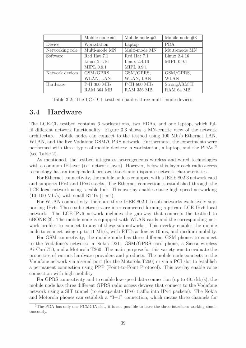
Mobile node #1 Mobile node #2 Mobile node #3
Device Workstation Laptop PDA
Networking role Multi-mode MN Multi-mode MN Multi-mode MN
Software Red Hat 7.1Linux 2.4.16MIPL 0.9.1
Red Hat 7.1Linux 2.4.16MIPL 0.9.1
Linux 2.4.16MIPL 0.9.1
Network devices GSM/GPRS,WLAN, LAN
GSM/GPRS,WLAN, LAN
GSM/GPRS,WLAN
Hardware P-II 300 MHzRAM 364 MB
P-III 600 MHzRAM 356 MB
StrongARM IIRAM 64 MB
Table 3.2: The LCE-CL testbed enables three multi-mode devices.
3.4 Hardware
The LCE-CL testbed contains 6 workstations, two PDAs, and one laptop, which ful-fil different network functionality. Figure 3.3 shows a MN-centric view of the networkarchitecture. Mobile nodes can connect to the testbed using 100 Mb/s Ethernet LAN,WLAN, and the live Vodafone GSM/GPRS network. Furthermore, the experiments wereperformed with three types of mobile devices: a workstation, a laptop, and the PDAs 3
(see Table 2).As mentioned, the testbed integrates heterogeneous wireless and wired technologies
with a common IP-layer (i.e. network layer). However, below this layer each radio accesstechnology has an independent protocol stack and disparate network characteristics.
For Ethernet connectivity, the mobile node is equipped with a IEEE 802.3 network cardand supports IPv4 and IPv6 stacks. The Ethernet connection is established through theLCE local network using a cable link. This overlay enables static high-speed networking(10–100 Mb/s) with small RTTs (1 ms).
For WLAN connectivity, there are three IEEE 802.11b sub-networks exclusively sup-porting IPv6. These sub-networks are inter-connected forming a private LCE-IPv6 localnetwork. The LCE-IPv6 network includes the gateway that connects the testbed to6BONE [3]. The mobile node is equipped with WLAN cards and the corresponding net-work profiles to connect to any of these sub-networks. This overlay enables the mobilenode to connect using up to 11 Mb/s, with RTTs as low as 10 ms, and medium mobility.
For GSM connectivity, the mobile node has three different GSM phones to connectto the Vodafone’s network: a Nokia D211 GSM/GPRS card phone, a Sierra wirelessAirCard750, and a Motorola T260. The main purpose for this variety was to evaluate theproperties of various hardware providers and products. The mobile node connects to theVodafone network via a serial port (for the Motorola T260) or via a PCI slot to establisha permanent connection using PPP (Point-to-Point Protocol). This overlay enable voiceconnection with high mobility.
For GPRS connectivity and to enable low-speed data connection (up to 49.5 kb/s), themobile node has three different GPRS radio access devices that connect to the Vodafonenetwork using a SIT tunnel (to encapsulate IPv6 traffic into IPv4 packets). The Nokiaand Motorola phones can establish a “3+1” connection, which means three channels for
3The PDA has only one PCMCIA slot, it is not possible to have the three interfaces working simul-taneously.
39

Correspondent Node
BSC CGSN
edge router
Mobile Nodes
IPv6−LAN Foreign Network
Default Gateway IPv6−LAN
Foreign NetworkVodafone’s live GPRS Network
WLAN Foreign Network
BTExact IPv6−Net6BONE
WLAN Foreign Network
Home Agent
WLAN Home Network
LCE IPv4−LAN
LAN WLANGPRS
������
Figure 3.4: Network-centric view of the LCE-CL testbed.
the downlink (39.6 kb/s) and one for the uplink. The AirCard750 connects to the networkwith a maximum downlink speed of 52.8 kb/s and 13.2 kb/s for the uplink, using a “4+1”connection. This overlay enables low-speed, high mobility data connection with RTTsaround 800 ms.
Figure 3.4 shows a network-centric view of the testbed. The LCE-CL enables horizon-tal and vertical handovers through the integration of seven networks based on differenttechnologies. There are three WLANs, one functioning as home network and the othertwo as foreign networks (i.e. visited networks), which enable homogeneous handovers.An IPv6-LAN allows the interconnection of the WLANs and mobile nodes to the IPv6backbone (i.e. 6BONE), and it enables wired-to-wireless handovers (functioning as a for-eign network). Finally, the IPv4-based LCE local network connected to the Vodafone’snetwork allows access to the live GPRS RAT. The testbed allows roaming from both,wired to wireless and cellular to wireless.
3.4.1 The Sentient Car
A vehicle-based mobile node was implement for experimental work related to context-aware networking, and as an extension of the LCE-CL testbed for additional testing.
In mobile computing, operating conditions change as clients move. This is particularlytrue for highly mobile nodes that not only change their location, but also their directionand velocity. The Sentient Car [102], shown in Figure 3.5, gathers experimental resultsfrom a highly mobile node and was the outcome of the joint collaboration between the
40
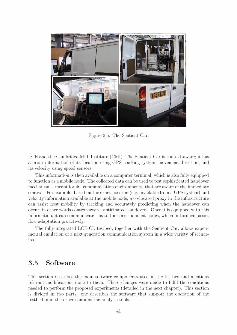
Figure 3.5: The Sentient Car.
LCE and the Cambridge-MIT Institute (CMI). The Sentient Car is context-aware; it hasa priori information of its location using GPS tracking system, movement direction, andits velocity using speed sensors.
This information is then available on a computer terminal, which is also fully equippedto function as a mobile node. The collected data can be used to test sophisticated handovermechanisms, meant for 4G communication environments, that are aware of the immediatecontext. For example, based on the exact position (e.g., available from a GPS system) andvelocity information available at the mobile node, a co-located proxy in the infrastructurecan assist host mobility by tracking and accurately predicting when the handover canoccur; in other words context-aware, anticipated handovers. Once it is equipped with thisinformation, it can communicate this to the correspondent nodes, which in turn can assistflow adaptation proactively.
The fully-integrated LCE-CL testbed, together with the Sentient Car, allows experi-mental emulation of a next generation communication system in a wide variety of scenar-ios.
3.5 Software
This section describes the main software components used in the testbed and mentionsrelevant modifications done to them. These changes were made to fulfil the conditionsneeded to perform the proposed experiments (detailed in the next chapter). This sectionis divided in two parts: one describes the software that support the operation of thetestbed, and the other contains the analysis tools.
41

3.5.1 Operational software
MIPL (Mobile IPv6 for Linux) is used to enable basic mobility in the LCE-CL testbed.This implementation of the MIPv6 specification was developed by Helsinki TechnicalUniversity [66] in Finland. Lancaster University has the oldest implementation, however,they stopped supporting this distribution in 1998. The last kernel supported by this groupwas 2.1.9 and the implementation has stopped being compatible since then.
Another reason, MIPL is open source and it is possible to modify the code and im-plement the mechanisms described in the next chapter. Significant changes were madeto the code aiming to optimise the protocol and improve its current performance in 4Gsystems. Chapter 4 includes the detailed description of the optimisation mechanisms, butthe main modifications made to MIPL are listed below.
• The Linux IPv6 Router ADVertisement Daemon (RADVD) is responsible for send-ing RAs according to configuration parameters (unsolicited RAs) or when respond-ing to a router solicitation [72]. This signalling is required to support IPv6 statelessautoconfiguration. Support was added to allow different RA frequency (Section4.5.1) below the ones recommended in [48]. Additionally, the modified RADVD isable to send alarms from kernel to user space when an incoming RA arrives to anyinterface—this modification was made to support PROTON (Chapter 5).
• Support was added for BU simulcasting (Section 4.5.3) by modifying the MN’ssource, in particular the send-binding update and send options routines. Also, themodified MIPL version support soft handovers—this optimisation is described inSection 4.10. The MN was modified to accept on-the-air packets from the oldinterface, even after the registration process had completed.
• In order to force handovers, the IPv6 routing table needs to be modified in corre-spondence to the expected scenario and conditions. A suite of scripts were developedto control the data in the routing table and dynamically allocate the appropriateroutes.
3.5.2 Analysis tools
• MGEN was used to generate UDP/IPv6 traffic and perform trace analysis to cal-culate raw network layer MIPv6 latency [63].
• TRPR was used to review the collected traces and produce suitable plots to showthe results [97].
• TCPDUMP was used to collect traces. The traffic passes through an intermediaterouter, and using tcpdump it is collected for further analysis. The collected protocolsare: UDP/IPv6, TCP/IPv6, and ICMPv6 [93].
• TCPTRACE was used to obtain performance graphs. Transport level plots weregenerated using tcptrace. Since the latest version of tcptrace for analysing TCPtraces does not offer any support for MIPv6, this analysis tool was also modified tohandle Mobile IPv6 connections [95].
42

3.6 Remarks
Experimental environments represent an essential tool in the deployment of future mobilenetworks. In this chapter, a loosely-coupled testbed was described. The main pointsthat distinguish the LCE-CL testbed from other setups are that (1) it fully evaluatesMIPv6 in heterogeneous environments, while other projects focus on the evaluation ofintra-technology handovers using MIPv6 or inter-technology handovers using MIPv4 dueto constraints in the architecture, and (2) Vodafone’s GSM/GPRS network. The LCE-CLtestbed enables a GSM/GPRS overlay using the actual provider’s network. Other projectsemulate a GPRS link or install an isolated GPRS network for experimental purposes, bothcases lack real-world conditions.
The testbed is used as the platform for analysing, solving, developing, and testing thefollowing technical issues:
• Seamless horizontal handovers using MIPv6
• MIPv6 performance during vertical handovers
• A client-based solution to improve performance in horizontal handovers for WLANs[74]
• Methods to minimise vertical handover latency
• Policy-based solution to manage multiple interfaces and support mobility
• QoS-based handover algorithms for overlay networks
• Context-aware algorithms for overlay networks
To conclude, it is fair to comment that one of the main advantages in the experimentalsetup presented in Chapter 3 is also its major limitation. On one hand, it was fundamentalfor this work to have access to core components in the Vodafone GSM/GPRS network, andto perform experiments under real network conditions. On the other hand, the requiredagreement with Vodafone posed some limitations on the publication of results, althoughthis did not affect the outcome of this dissertation.
43

44

Chapter 4
Evaluation and NetworkingImprovements for 4G Systems
This chapter summarises the practical experiments performed to evaluate the impact ofinter-networking (i.e. vertical handovers) on the network and transport layers. Basedon experiments and observations, a number of inter-technology handover optimisationtechniques are proposed and evaluated in this chapter—RA frequency, BU simulcasting,RA caching, and soft handovers.
This work targets networking issues in future 4G communication systems, in particular,those related to the impact of vertical handovers and terminal mobility on the performanceof the TCP/IP stack.
The main objectives are:
1. Measure the latency when the terminal is roaming between heterogeneous net-works,
2. Characterise the vertical handover latency, identifying its main components,
3. Identify the main performance problems during vertical handovers and their impacton the TCP/IP stack,
4. Explore different optimisation methods that decrease the overall latency, and eval-uate each of them using the LCE-CL testbed,
5. Demonstrate the efficiency of different optimisations, and the need for a high-levelmobility support middleware to enable informed decisions and drive the handoverprocess.
In this chapter a detailed evaluation of Mobile IPv6 (using the testbed introduce inChapter 3) is presented. The most important improvements to this protocol are mentionedin Section 4.1. The testing environment and conditions are mentioned in Section 4.2. Thevertical handover latency study is summarised in Section 4.3 and latency partition detailedin Section 4.4. Different handover optimisations are explored, and results are presentedin Section 4.5. Related work is presented in Section 4.6, while Section 4.7 concludes thechapter.
45

4.1 Optimisations to Mobile IPv6
The handover latency using basic MIPv6 is proportional to the round-trip time necessaryfor a binding update message to reach either the MN’s home agent or a correspondentnode. This is further analysed in Section 4.4.
Network-layer latency on wireless links can be very high, especially for interactive ap-plications that have real-time requirements. Therefore, the research community is workingon mechanisms that decrease this latency as much as possible, at least to levels that sup-port real-time applications in a seamless manner.
Two of the most significant proposals are Fast Handovers for Mobile IPv6 (FMIPv6)[53] and Hierarchical Mobile IPv6 (HMIPv6) [88]. FMIPv6 [53] aims to decrease the totallatency to almost only the layer-two handover time. This approach has been shown toperform well in intra-technology (i.e. horizontal) handovers [22, 7].
The HMIPv6 approach is designed to reduce the degree of signalling required andto improve handover speed for mobile connections by managing local mobility in a moreefficient way. Previous work [19, 20] has analysed which of these approaches (i.e. FMIPv6and HMIPv6) performs better, the conclusion being that a combined approach would beoptimal. However, given the implementation complexity that this would require, theFMIPv6 optimisation by itself is sufficient (this has been experimentally evaluated in [7]).
Future 4G systems, in which heterogeneity will be the rule instead of the exception,present some challenging characteristics when performing vertical (also known as inter-technology) handovers:
• Bandwidth, delay, and packet losses can be radically different among the differ-ent candidate access network technologies (e.g., IEEE 802.3, IEEE 802.11, GPRS,UMTS, Bluetooth, etc.)
• There are certain technologies that are usually globally available (e.g., GPRS,UMTS), whereas there are others that are only present in certain locations (e.g.,WLAN, Bluetooth). This fact dictates an overlay-based model, where “movingup” (handing off from a locally available access technology to a globally availablenetwork) is not equivalent to “moving down” (roaming from a globally availablenetwork to a locally available technology). This needs to be taken into account,while in horizontal handovers the situation does not arise.
Therefore, the vertical handover process is affected by many different parameters, andthe solutions needed to improve it must handle this complexity. Moreover, optimisationmethods that have been tested for homogeneous environments do not necessary work wellin vertical handovers, and it should not be assumed that everything in the horizontalscenario brings benefits to the heterogeneous case.
This chapter aims to clarify this situation; a thorough evaluation of MIPv6 is per-formed and the main effects of mobility on the TCP/IP stack are mentioned. During thisprocess, the possible handover scenarios and optimisations are studied with the intentionof defining the best combination and its scope. Suggestions for particular optimisationmethods, which can be applied under a certain set of conditions are formulated. Finally,the need for middleware to support mobility and handle these intrinsic complexities in4G networks is motivated.
46
4.2 Experimental environment
The testbed was operated under the following conditions:
1. The movement detection was performed based on Neighbour Discovery (i.e. routeradvertisements). In this case, the mobile node waits to receive a router advertise-ment after it arrives at the visited network.
2. In the case of the vertical handover, when the new interface has a lower priority,compared to the previous one, the mobile node waits until the old access router isunreachable and then generates a router solicitation message.
3. Unless stated otherwise, all access routers are set to multicast RAs, according tothe recommended parameters and values specified in [92] (the effects of these valuesare analysed in Section 4.5.1)
4. For all the cases considered in these tests, the multi-mode mobile device had allof its interfaces (e.g., LAN, WLAN and GPRS) powered on and listening to theirspecific networks.
5. The soft handover and RA caching optimisations follow the “make-before-break”philosophy, meaning that at least one handover-related process starts before break-ing the connection with the previous access router.
6. The RA frequency and BU simulcasting methods follow the “break-before-make”philosophy. The MN waits until the current access router is unreachable, and thenit begins the handover process.
7. The results presented in Section 4.5.4 (i.e. soft handovers) consider the MN listen-ing on both interfaces simultaneously, while performing the vertical handover. Incontrast, a hard handover occurs when the MN listens exclusively on one interface—expecting packet losses.
8. All hosts run Red Hat 7.1, with Linux 2.4.16 and the MNs run MIPL 0.9.1. Forthese experiments the workstation and the laptop are used for the experiments,equipped with an Orinoco wireless silver card and a Sierra Wireless Aircard 750 forIEEE 802.11b and GPRS connections, respectively.
For the tests conducted, handovers were forced by filtering incoming RAs at the net-work layer using IP6tables-based filters [46]. For testing handovers, data transfers wereinitiated by the multi-mode device over the Visited Network access router. During thisdata transfer (e.g., ICMP packets or HTTP), vertical handovers to different visited net-works are conducted (i.e. a different RAT). In the testbed, all traffic passes through anintermediate router, and traffic traces are taken using tcpdump [93], to/from the corre-spondent node, allowing us to collect traces at this point for further analysis.
47

The following systematic errors need to be considered in every experimental measure-ments:
• Clock synchronisation: The network machines are synchronised using the NetworkTime Protocol (NTP), which has a clock accuracy of 10 ms.
• Clock accuracy: The packet traces were collected using tcpdump [93]. This tool setsa time-stamp for each packet that arrives. It has an accuracy of 1 ms.
Therefore, all the experimental values presented in the current chapter and Chapter6 should include a maximum error value of 11 ms.
4.3 Experiments to evaluate MIPv6
Firstly, experiments to evaluate MIPv6 during vertical handovers are performed. Thesetests aim to measure the impact of mobility on the TCP/IP stack. Therefore effects onlayer 3 and layer 4 are analysed for the following scenarios: GPRS-to-WLAN, WLAN-to-GPRS, GPRS-to-LAN, LAN-to-GPRS, WLAN-to-LAN, and LAN-to-WLAN (the exper-iments were carried out using the LCE-CL testbed). The most relevant results from thestudy are explained in the next section.
• Measurements of MIPv6 performance during vertical handovers at the network layerfor every possible scenario, using ICMP as a test case protocol. Due to the simplicityof this protocol, it is the most appropriate way to measure network layer latency.ICMP does not add too much overhead to the networking process.
• The most popular test scenario in heterogeneous environments is the handover be-tween WLAN and GPRS networks, for which results are included showing the UDPover MIPv6 handover latency.
• MIPv6 transport layer measurements to determine the effects of mobility on TCPusing HTTP as a test case application, due to the fact that almost 85% of theInternet traffic is generated by this type of connection [62].
• Packet overhead added by different protocols, considering routing between the MNand the CN and between mobile nodes, in the different test cases.
4.3.1 Mobile IPv6 network layer performance (IP)
To calculate the latency at the network layer based on packet loss, ICMPv6 traffic isgenerated between the correspondent node and the mobile node. The correspondent nodesends small ICMPv6 packets (104 bytes) every 200 ms. Thus, the handover latency is theproduct of the number of packets lost multiplied by the time interval between the packets(see Figure 4.1).
Results shown in Figure 4.1 suggest that Mobile IPv6 protocol was designed for mo-bility management without caring about the underlying technologies. When dealing withheterogeneous handovers, MIPv6 does not perform as expected and in most scenarios
48

0
1000
2000
3000
4000
5000
6000
7000
8000
9000
Han
dove
r la
tenc
y (m
s)
Type of handover
Vertical handover latency
40 handover iterations
LAN −> GPRSmean: 2675 msstd: 1227 ms
GPRS −> LANmean: 6755 msstd: 1100 ms
LAN −> WLANmean: 700 msstd: 365 ms
WLAN −> LANmean: 2810 ms
std: 365 msWLAN −> GPRSmean: 2325 ms
std: 916 ms
GPRS −> WLANmean: 6845 msstd: 1135 ms
Figure 4.1: MIPv6 network layer vertical handover latency.
handover
GPRS
WLAN
0
0.1
0.2
0.3
0.4
0.5
0.6
0.7
0.8
0 10 20 30 40 50 60 70
Late
ncy
(sec
)
Time (sec)
UDP Latency (CN−>MN)
mgen, CN−>MN
Figure 4.2: UDP over MIPv6 vertical handover latency.
latency exceeds acceptable limits (not even close to support for real-time applications).The values presented can have a precision error of 200 ms due to the experimental setup,thus handover latency from IEEE 802.11b to GPRS is between 2200 ms and 2400 ms. Infact, the mean handover latency for this scenario is 2325 ms. The mean and standarddeviation values shown were calculated using the data collected over 40 iterations for eachhandover scenario.
4.3.2 Mobile IPv6 transport layer performance (UDP)
In addition to the MIPv6 performance at the network layer, it is also interesting toinvestigate how current transport protocols are affected by mobility in heterogeneousenvironments. This section discusses related results collected during some experimentsthat were performed using the LCE-CL testbed.
Several tests were done using MGEN [63] in order to analyse UDP effects on MIPv6.During the experiments, the receiver (i.e. mobile node) collects transmitted packets andcreates logs, which are then analysed to extract statistical data (using TRPR [97]) such
49

0
1000
2000
3000
4000
5000
6000
7000
8000
9000
Han
dove
r la
tenc
y (m
s)
Type of handover
Vertical handover latency
10 handover iterations
LAN −> GPRSmean: 4996 ms
std: 561 ms
GPRS −> LANmean: 6525 msstd: 1176 ms
LAN −> WLANmean: 0 msstd: 0 ms
WLAN −> LANmean: 0 msstd: 0 ms
WLAN −> GPRSmean: 3806 ms
std: 310 ms
GPRS −> WLANmean: 6896 msstd: 1118 ms
Figure 4.3: MIPv6 transport layer (TCP) vertical handover latency.
as perceived latency at the mobile node.
Figure 4.2 shows the latency at the mobile node during an average iteration. For thistrial, the correspondent node starts sending UDP packets (packet size 80 bytes, every 50ms). After 22 s a handover occurred and 57 packets are lost. This implies a handoverlatency of 2850 ms, which is a value very close to the network layer latency for the sametechnologies, around 2325 ms as shown in Figure 4.1.
4.3.3 Mobile IPv6 impact on the transport layer (TCP)
The impact of vertical handovers on the transport layer is evaluated by collecting traceswhilst downloading a file from the CN to the mobile terminal. Results are included forevery possible scenario using the LCE-CL testbed. The values in Figure 4.3 show the totaldelay when the MN moves between two access points that belong to different technologies.Using the complete picture offered by Figures 4.1 and 4.3, Some early patterns in thebehaviour of MIPv6 when dealing with heterogeneous technologies can be observed, aswell as the mobility impact on the TCP/IP protocol stack.
When the MN moves “up” in the model (from a faster network to a slower one withhigher RTTs) the latency is smaller, e.g., to handoff from WLAN to GPRS takes 5.5 s,whereas when the terminal moves to a lower layer (i.e. to a faster access technology), thedisruptions last for longer (the handover from GPRS to WLAN takes about 7.4 s). Thisrelation is also true for the latency values at the network layer shown in Figure 4.1.
The values are larger for the TCP latency in every scenario, compared to the network-layer latency. This is due to the residual TCP back-off time or the interval for which theTCP flow remains (exponentially) backed-off even after the IP-level handover. This delayis considered part of what I termed adaptation component, which affects the handoverlatency at layer 4 (Section 4.4 explains this concept). The mean and standard deviationvalues shown were calculated using the data collected over 40 iterations for each handoverscenario.
50

4.3.4 Packet overhead
This section introduces an analytical study of the protocol overhead introduced by MobileIPv6, by comparing it with the overhead present in IPv4 and plain IPv6.
Mobile IPv6 adds an extra IPv6 header (40 bytes) to every packet sent/received bythe MN in the MN-CN portion of the path followed by the data packets. If the RouteOptimisation support is enabled in an ongoing communication between a MN and a CN, a24-byte overhead (due to the addition of a home address destination option in the packetssent by the MN or a Type II Routing Header in the packets sent by the CN) is addedinstead of the IPv6 header. For the case of two MNs that are communicating, a 48-byteoverhead is present, because both the home address destination option and the routingheader are present in every packet of the communication.
Figure 4.4 shows graphically the packet overhead for different kinds of IP payloads:
• TCP 40 bytes. Mostly TCP packets which carry TCP acknowledgements, but notpayload. This is the minimum TCP packet size.
• TCP 552 bytes. This packet-size (or 576 bytes) is used by those TCP implemen-tations that do not use path MTU discovery.
• TCP 1500 bytes. This is the maximum standard Ethernet payload size.
Because a large proportion of the TCP traffic is generated by bulk transfer applica-tions, such as HTTP and FTP, the majority of the packets seen in the Internet areone of the previous sizes [62].
• UDP VoIP GSM. UDP-RTP1 packets carrying VoIP payload using the GSMcodec (33 bytes per packet).
• UDP VoIP G723.1. UDP-RTP packets carrying VoIP payload using the G723.1codec (20 bytes per packet).
• UDP VoIP G711. UDP-RTP packets carrying VoIP payload using the G711 codec(240 bytes per packet).
• UDP VoIP LPC10. UDP-RTP packets carrying VoIP payload using the LPC10codec (7 bytes per packet).
UDP-RTP VoIP packets are analysed because VoIP has been one of the emerging ser-vices in the last several years and also because the packet overhead is a critical parameterin this application (even when using IPv4).
Figure 4.4 shows that even for 552-byte TCP packets, the overhead is not negligiblewhen Mobile IPv6 is used (about 14–16%). The use of Mobile IPv6 has a great impacton the packet overhead in VoIP packets—sometimes even tripling it compared with theIPv4 case. Therefore, special care should be taken in the design of the network (i.e.resources, queue management, QoS mechanisms, etc.), especially if applications requestQoS guarantees. Thus, the added overhead to support mobility in 4G networks needsto be considered; current deployments (designed for IPv4 traffic) could be insufficient forcarrying the new IPv6-mobility-enabled traffic.
1The RTP header is 12 bytes
51
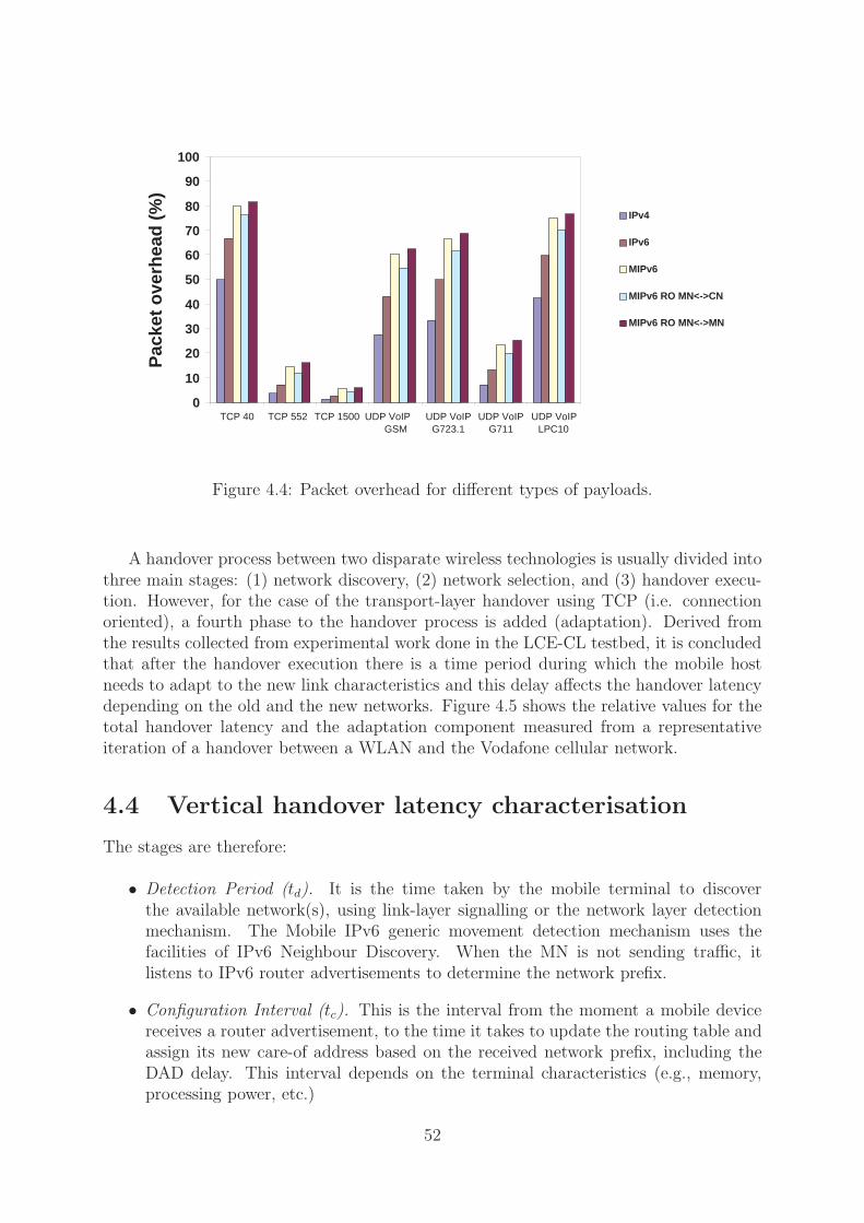
0
10
20
30
40
50
60
70
80
90
100
TCP 40 TCP 552 TCP 1500 UDP VoIP GSM
UDP VoIP G723.1
UDP VoIP G711
UDP VoIP LPC10
Pac
ket o
verh
ead
(%)
IPv4
IPv6
MIPv6
MIPv6 RO MN<->CN
MIPv6 RO MN<->MN
Figure 4.4: Packet overhead for different types of payloads.
A handover process between two disparate wireless technologies is usually divided intothree main stages: (1) network discovery, (2) network selection, and (3) handover execu-tion. However, for the case of the transport-layer handover using TCP (i.e. connectionoriented), a fourth phase to the handover process is added (adaptation). Derived fromthe results collected from experimental work done in the LCE-CL testbed, it is concludedthat after the handover execution there is a time period during which the mobile hostneeds to adapt to the new link characteristics and this delay affects the handover latencydepending on the old and the new networks. Figure 4.5 shows the relative values for thetotal handover latency and the adaptation component measured from a representativeiteration of a handover between a WLAN and the Vodafone cellular network.
4.4 Vertical handover latency characterisation
The stages are therefore:
• Detection Period (td). It is the time taken by the mobile terminal to discoverthe available network(s), using link-layer signalling or the network layer detectionmechanism. The Mobile IPv6 generic movement detection mechanism uses thefacilities of IPv6 Neighbour Discovery. When the MN is not sending traffic, itlistens to IPv6 router advertisements to determine the network prefix.
• Configuration Interval (tc). This is the interval from the moment a mobile devicereceives a router advertisement, to the time it takes to update the routing table andassign its new care-of address based on the received network prefix, including theDAD delay. This interval depends on the terminal characteristics (e.g., memory,processing power, etc.)
52

−10.000 s
−15.000 s
7060504030
relative time
segments
MN CN
First packet
Last packet
received at nCoA
received at oCoA
GPRS
WLAN
MN sendsBU to HAMN sendsBU to CN
Tt ~ 4.5s
ta ~ 9s
Figure 4.5: Adaptation component for the test scenario WLAN-to-GPRS.
The DAD delay was not significant in the described scenario due to the lack ofconcurrent mobile hosts roaming simultaneously. In an optimistic case, the DADdelay is very small compared to the other latency components. However, whendealing with more mobile nodes the probability of address collision increases andthe DAD delay should be considered. For experimental results on this topic, anenvironment where the number of mobile nodes moving can be controlled needs tobe available. Further discussion on this issue is included in [5, 70].
• Registration Time (tr). This is the delay between the delivery of the binding updateto the home agent and correspondent nodes, and the reception of the first packet atthe new interface—with the new care–of address as the destination address. Thistime component increases if the mobile terminal is configured to wait for the bindingacknowledgement sent by the correspondent node, as mentioned in Section 11.7.2of [48].
• Adaptation Time (ta). When dealing with vertical handovers at the transport level,ta needs to be considered in the total handover latency. This delay only happenswhen the mobile host adapts the connection to the new technology at the transportlayer, adjusting the TCP state machine parameters (e.g., congestion window size,timeout timers, etc.), due to the heterogeneous nature of the technologies—this iscaused by the normal TCP settling period, but augmented by the differences in thelink characteristics. Thus for the case of TCP transmissions, the transport-layerlatency (Tt) is equivalent to the network-layer latency (Tn) plus the adaptationcomponent, as shown in Figure 4.6.
The definition of handover latency in Mobile IPv6 is limited to the period of timewhen the mobile node is unable to receive IPv6 packets both due to the link (i.e. layer2) switching delay and IP protocol operations (i.e. network-layer handover), as defined in[48]. However, this chapter analyses the latencies in both UDP/MIPv6 and TCP/MIPv6
53

MN CN
td
tc
tr
Router Solicitation
Router AdvertisementRa
Rs
BU
BU
BA
ta
DATA
ACKs
Handover Trigger
netw
ork−
laye
r la
tenc
y (T
n)
old AR new AR
TC
P/M
IPv6
late
ncy
(Tt)
Figure 4.6: Network and transport layers’ latency partition.
for transport-layer handovers. For the UDP case, the latency is equivalent to the network-layer latency. However, for TCP transmissions the term of handover latency is extendedto consider the ta component.
In this study handover latency is divided into: network-layer handover latency andTCP handover latency. The former matches the definition included in [48], and the latteris defined as the period of time when the mobile node is unable to receive IPv6 packets witha stable pattern (meaning that the throughput is close to the link’s normal behaviour) dueto the link switching delay, the IP protocol operations, and the adjustments performedat the transport layer due to huge disparities in link characteristics.
It has been observed that 85% of the traffic in the Internet is generated by TCPconnections [62]. Therefore, proposals to minimise TCP handover latency during verticalhandovers are essential for future seamless roaming—a possible approach is to reduce tain order to improve the overall latency.
4.4.1 Analytical representation of latency partition
As mentioned above, the impact of vertical handovers on the network layer is characterisedusing ICMPv6 protocol, and the effects at the transport layer when using UDP and TCPas transport protocols. The cases of the GPRS-WLAN-LAN testbed are included based oncurrent standard wireless technologies to outline an experimental study that determinesthe impact of each individual component in the overall handover latency.
The network-layer latency is given by:
Tn = td + tc + tr (4.1)
wheretd is a random variable with probability p(td):
p(td) =1 −
∫ td
0ptRA
(t)
tRA
(4.2)
54
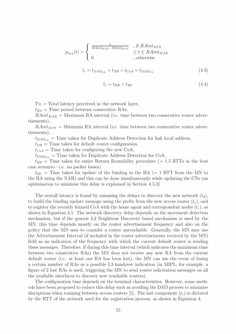
ptRA(t) =
1RAintMAX−RAintMIN
, if RAintMIN
≤ t ≤ RAintMAX
0 , otherwise
tc = tDADLL+ tDR + tCoA + tDADNL
(4.3)
tr = tRR + tBU (4.4)
Tn = Total latency perceived in the network layer,tRA = Time period between consecutive RAs,RAintMAX = Maximum RA interval (i.e. time between two consecutive router adver-
tisements),RAintMIN = Minimum RA interval (i.e. time between two consecutive router adver-
tisements),tDADLL
= Time taken for Duplicate Address Detection for link local address,tDR = Time taken for default router configuration,tCoA = Time taken for configuring the new CoA,tDADNL
= Time taken for Duplicate Address Detection for CoA,tRR = Time taken for entire Return Routability procedure (= 1.5 RTTs in the best
case scenario—i.e. no packet losses)tBU = Time taken for update of the binding in the HA (= 1 RTT from the MN to
the HA using the NAR) and this can be done simultaneously while updating the CNs (anoptimisation to minimise this delay is explained in Section 4.5.3)
The overall latency is found by summing the delays to discover the new network (td),to build the binding update message using the prefix from the new access router (tc), andto register the recently formed CoA with the home agent and correspondent nodes (tr), asshown in Equation 4.1. The network discovery delay depends on the movement detectionmechanism, but if the generic L3 Neighbour Discovery based mechanism is used by theMN, this time depends mostly on the router advertisement frequency and also on thepolicy that the MN uses to consider a router unreachable. Generally, the MN may usethe Advertisement Interval (if included in the router advertisements received by the MN)field as an indication of the frequency with which the current default router is sendingthese messages. Therefore, if during this time interval (which indicates the maximum timebetween two consecutive RAs) the MN does not receive any new RA from the currentdefault router (i.e. at least one RA has been lost), the MN can use the event of losinga certain number of RAs as a possible L3 handover indication (in MIPL, for example, afigure of 2 lost RAs is used, triggering the MN to send router solicitation messages on allthe available interfaces to discover new reachable routers).
The configuration time depends on the terminal characteristics. However, some meth-ods have been proposed to reduce this delay such as avoiding the DAD process to minimisedisruptions when roaming between access routers [5]. The last component (tr) is dictatedby the RTT of the network used for the registration process, as shown in Equation 4.
55

WLAN ⇒ GPRS Mean Std. Dev. Min. Max.Detection time (td) 808 320 200 1148Configuration time (tc) 1 0 1 1Registration time (tr) 2997 416 2339 3649Total handover latency (tn) 3806 327 3323 4438
GPRS ⇒ WLAN Mean Std. Dev. Min. Max.Detection time (td) 2241 968 739 3803Configuration time (tc) 1 0 0 1Registration time (tr) 4654 1698 2585 7639Total handover latency (tn) 6897 1178 5322 8833
LAN ⇒ GPRS Mean Std. Dev. Min. Max.Detection time (td) 1168 460 347 2070Configuration time (tc) 1 0 1 1Registration time (tr) 3307 585 2299 4759Total handover latency (tn) 4476 520 2806 5107
GPRS ⇒ LAN Mean Std. Dev. Min. Max.Detection time (td) 2058 1030 1 3257Configuration time (tc) 1 0 1 1Registration time (tr) 4466 1449 2357 7183Total handover latency (tn) 6525 1229 4011 8197
Table 4.1: Latency partition for vertical handovers using MIPL(milliseconds).
4.4.2 Experimental latency partition
The impact that hard handovers (i.e. only one active interface at the same time) have onthe network and transport layers have been studied. To demonstrate latency partitioning,the cases of GPRS-WLAN-GPRS and GPRS-LAN-GPRS are included because these arethe most common scenarios. Table 4.1 shows the average values over 40 iterations of thelatency components for different handover scenarios.
The raw latency values included in the tables are too high to even consider usingMIPv6 (or its implementation, MIPL) with real-time applications for which the tolerateddelays are less than 100 ms. For example, the handover latency from a hotspot to thecellular system takes around 6.8 seconds to complete, and in the scenario where theterminal moves from a cellular system to an IEEE 802.11b access point there is has anoverall delay of 3.8 seconds.
As td is a random variable, that depends on the RA frequency, the values for thestandard deviation in every case are very large—around 40% and 50% of the mean value.Ideally, when the mobile host moves from a high-RTT and low-bandwidth network (e.g.GPRS) to a low-RTT and high-bandwidth access technology (e.g. WLAN), the regis-tration time should be smaller than the opposite case—moving from a lower layer to anupper layer—as RA frequencies are higher in the lower networks and also because thetime required for the signalling to be completed is lower. Table 4.1 shows that this is notnecessarily true for all the cases.
The registration time is basically related to the RTT of the network; since WLANoffers links that have low RTTs, then tr for GPRS to WLAN handover should be smaller
56

Retransmissions
First ACK
Web Server
from GPRS
Time (sec)
Time (min)
First ACK from WLAN
WLAN−>GPRS−>WLAN Vertical Handoff
WLAN−>GPRS Handoff GPRS−>WLAN handoff
Closeup of WLAN−>GPRS handoff Closeup of GPRS−>WLAN handoff
Seq
uenc
e O
ffset
(by
tes)
Seq
uenc
e O
ffset
(by
tes)
Seq
uenc
e O
ffset
(by
tes)
Time (sec)
No RetransmissionsExcess Buffering
(Source RTO skewed up!)
0
5000000
10000000
15000000
20000000
25000000
30000000
00:0000:00 01:0001:00 02:0002:00 03:0003:00
12940000
12960000
12980000
13000000
13020000
13040000
23 24 25 26 27 28 29 30 31 32
13450000
13500000
13550000
13600000
13650000
166 168 170 172 174 176 178
Figure 4.7: Close-up of a handover showing the effects of excess buffering.
than for its counterpart (i.e. WLAN to GPRS). The measured values show the opposite.This is because the Mobile IPv6 implementation used in these tests (MIPL) tries to sendthe BU to the CNs piggybacked in a data packet. Therefore, the BU is sent in thefirst data packet after the movement detection (or after a certain maximum amount oftime, to avoid delaying the binding update so much). Because of the high buffering in theGPRS GGSN, the MN perceives an inflated RTT, and hence, an increased RetransmissionTimeout (RTO). Consequently, the registration process can complete only after the sourceeventually retransmits with a high value of the RTO. This leads to a very high latencywhen moving from the cellular network to a hotspot (see Figure 4.7 2), affecting the trdelay.
There is also an additional feature that affects the overall handover latency, which isrelated to the Movement Detection mechanism specified in Section 11.5 of the MIPv6 RFCdocument [48], and directly affects the td delay. The specification does not include policiesto determine when the mobile node needs to perform Router Discovery, due to the loss ofconnectivity through the current network. However, it does enumerate certain indicationsthat should be considered (e.g. Advertisement Interval field) to detect unreachability ofthe current access router.
For the case of MIPL [66], which is the MIPv6 implementation used in the LCE-CLtestbed, there are different policies according to certain conditions when deciding the
2Source: R. Chacravorty
57

Figure 4.8: Lazy cell switching.
handover. The Movement Detection mechanism included in MIPL covers the followingsituations:
• No movement detection. If the detected router advertisement comes from the currentrouter, then the MN does not perform any handover action. Interpreting this, theMN is still within the coverage of the current access router and there is no othernetwork available.
• Horizontal Handover. This occurs when the incoming RA is received through thesame interface—and it is not sent by the current access router, which implies thatboth the new and old access routers are within the same layer (i.e. wireless tech-nology). Under these conditions, MIPL executes the handover using the Eager CellSwitching (ECS) algorithm. The RA received is processed immediately, followed bythe configuration and registration procedures.
• Vertical Handover. The incoming RA comes from a different access router, and it isreceived on a different interface from the one being used. This means that the newand old routers of attachment belong to different access technologies. In this caseMIPL checks if the new network interface (NIC) is preferred over the old interface.If the new one is preferred, then the RA is processed, and if not, MIPL triggers athe Lazy Cell Switching (LCS) algorithm for vertical handovers.
The LCS algorithm implemented in MIPL needs to be described in order to understandits effect on the handover latency. If the interface that receives the RA from the newaccess router (i.e. recently available network) is different from the one being used, thenthe terminal waits until the current network is unreachable. As shown in Figure 4.8, theMN detects that the old access router is not reachable when it does not receive RAs for
58

Figure 4.9: Eager cell switching.
a period of time equal to twice the RA interval (2 ∗ RAinterval). The MN sends a routersolicitation after 8 s because the RA interval is configured to 4000 ms for the exampleshown in Figure 4.8.3
For this implementation of the LCS in MIPL, the current network has higher prioritythan any other technology available, without considering the link characteristics. Thus,if no other policy is taken before the handover execution, a slower network can have ahigher priority than a faster technology. In this case, the mobile node applies the LCSalgorithm instead of ECS when moving from the cellular system to an available hotspot,resulting in a bigger value of tr as shown in Table 4.1 on page 58.
The importance of applying the appropriate handover execution method can be ob-served (in MIPL either LCS or ECS) in figures 4.8 and 4.9. When ECS is applied, whilstperforming a downward (to handoff from a global coverage to a local coverage accesstechnology) handover, the total latency was approximately 500 ms as shown in Figure4.9, whereas for the case where LCS was used (i.e. when the slower interface had a higherpreference value), the handover process took approximately 7.5 s in total (see Figure 4.8).
This situation motivates the need for a policy-based system to take well-informedhandover-related decisions, and deal with the complexities posed by heterogeneous net-works. The handover performance can be improved just by having an a priori policyto set the interfaces’ preferences according to the link characteristics. For example, theGPRS preference is set to a lower value than the IEEE 802.11a interface due to its higherRTT values. Thus, when a downward handover occurs, the ECS algorithm is appliedand not the LCS execution method, improving the vertical handover performance in thisscenario.
3These values are the ones recommended in the Mobile IPv6 RFC.
59

RA Interval WLAN− >GPRS GPRS− >WLANMinRA–MaxRA td (GPRS overhead, %) td (WLAN overhead, %)
300 ms–400 ms 551 ms (4.7) 234 ms (0.0210)200 ms–300 ms 360 ms (9.5) 242 ms (0.0317)100 ms–200 ms 324 ms (19.0) 174 ms (0.0633)40 ms–70 ms 217 ms (47.5) 86 ms (0.1583)
Table 4.2: RA frequency variation effects on WLAN and GPRS networks.
4.5 Impacting MIPv6 latency
As shown in the previous section, the total MIPv6 handover latency is the sum of the IPlayer latency (Tn) and the TCP adaptation time. This section describes mechanisms toimprove the MIPv6 latency and minimise disruptions in the connectivity while roamingbetween heterogeneous networks. The following methods are discussed: RA frequency,RA caching, BU simulcasting, and soft handover to improve networking performance.
4.5.1 RA frequency
Higher RA frequency improves performance due to the reduction in td, which results insmaller latencies during vertical handovers. There are two methods related to the Neigh-bour Discovery protocol that can reduce the network discovery time: (1) incrementingthe RA frequency and (2) generating an on-demand router solicitation.
Related to incrementing the RA frequency, the current Mobile IPv6 specification [48]considers this topic and proposes shorter intervals—30 ms (MinRtrAdvInterval) to 70 ms(MinRtrAdvInterval). However, decreasing the RA interval is not without cost, as this hasa direct impact on the link performance, caused by the added overhead. Thus, there is anobvious trade-off involved, especially over reduced-capacity links such as GPRS networks.
In order to evaluate the RA frequency’s impact on vertical handovers, a modifiedversion of the Linux IPv6 RA daemon (radvd [79]) is used to perform experiments usingdifferent RA interval values, including the ones specified in [48]. Table 4.2 shows the effectof varying RA interval on mean td values obtained from over 20 runs. Based on theseresults, it can be observed that although increasing the RA frequency reduces the totallatency, it is not the best option for low-bandwidth networks such as GPRS.
For example, in the case of WLAN, increasing the RA frequency from 300–400 ms(min–max) to 40–70 ms represents a marginal increase in the overhead—considering abandwidth of 8 Mb/s in the link—and the benefits in td (as a consequence, in the overalllatency) are very significant (obtaining a reduction of 65%), whereas this same situationon the GPRS link has completely different effects. Reducing the RA interval to 40–70 msmeans using almost 50% of the link to transmit RAs (considering a 36.9 kb/s link of a ’3+1’GPRS phone), however, there is a 61% reduction in the td delay. After this analysis, forthe case of the GPRS overlay the following RA interval values are suggested to maintaina convenient trade-off between added overhead and benefits: MinRtrAdvInterval = 500ms and MaxRtrAdvInterval = 1000 ms (see [13] for details).
60

Upward handover No BU simulcasting BU simulcasting Reduction
LAN to WLAN 7.5 ms 1.9 ms 75.0%WLAN to 3G 750 ms 156 ms 79.2%3G to GPRS 2500 ms 1000 ms 60.0%WLAN to GPRS 2500 ms 506 ms 79.8%
Table 4.3: BU-simulcasting reduction (best case analysis).
4.5.2 RA caching
This method aims to eliminate the discovery time (td) from the total latency. The mainprinciple behind this optimisation is that the mobile node caches every incoming RA, andwhen it needs to perform a vertical handover (specifically upward handovers) because ofthe loss of coverage, the mobile terminal does not wait for the next incoming RA fromthe currently available access network, but instead it uses a previously cached RA whenpossible, reducing (td) to zero.
It is important to mention that this optimisation is only useful when there is an over-lap between the coverage of the old and new access routers. The algorithm was originallydesigned for horizontal handovers between overlapping cells. A detailed description of thisversion is included in [74]. This algorithm was extended to support vertical handovers.However it only reduces td when a cached RA exists (i.e. for the upward handover sce-nario).
The optimisation was implemented as a module, part of a middleware system to sup-port complete mobility (see Chapter 5). The RAs are extracted from the network stackbefore they reach the MIPv6 module. These RAs are maintained in the RA-cache (ac-cording to certain policies such as time-to-live and signal strength). Then, when the MNperforms a handover, high-level policies decide if an upward handover will occur and checkfor the cached RA to process it.
4.5.3 BU simulcasting
During IP-level handovers, the time required to communicate the new care-of address tothe home agent and correspondent nodes (tr) is typically limited by the RTT to the CNand the HA. A technique that can be used to minimise the impact of tr on the overalllatency (Tn) is to simulcast the BUs. Thus, the registration time is limited by the RTT ofthe fastest network and not by the latency of the new network as specified in the MobileIPv6 specification, (Section 11.7 [48]). The tr delay is given by: Rt = TRR + tBU ≥2.5RTT . Table 4.3 shows the reduction values for different scenarios, using estimatedRTT values. The reduction in (td) is calculated using the following RTT values: LAN=200ms, WLAN=3 ms, 3G=300 ms, and GPRS=1000 ms.
61

4.5.4 Soft handover
The optimisations discussed thus far have been related to hard handover; the MN dis-connects (stops listening) from the old interface, and just then starts listening to the newinterface. As a result, packets that were already on-the-air, sent by the CN before itrealises that the MN has moved to another network or those destined to the old networkinterface, are discarded.
These packets need to be retransmitted by the source, leading to a reduction in per-formance because of vertical handovers. However, vertical handovers can be made “soft”to improve inter-networking.
Traditionally, soft handovers (the MN attaches to the new network before breakingthe connection with the old access point) have been exploited for link-layer handoversin cellular networks. This chapter analyses soft vertical handovers between highly het-erogeneous networks. To enable this study using the testbed, the source code of MIPL[66] was modified so that during the handover process every on-the-air packet destinedto the previous interface (i.e. old interface) is read and passed to the application, despitethe incongruity between the packet’s destination address (old interface’s address) and thecurrent terminal’s CoA (new interface’s address).
Thus, the MN keeps receiving packets from the previous network and meanwhile, itcompletes the registration process with its new CoA and starts receiving packets throughthe new interface, which has the CoA assigned. It can be thought that using soft handoverswould enable the seamless roaming. However, the benefits are not always evident due todrastic differences in link characteristics (heterogeneous networks).
62

1808
4000
00
1808
3000
0018
0840
0000
1815
0000
00
1808
2400
00
1808
3500
00
1808
2500
00
1808
3800
00
1810
0000
00
1808
2200
00
1808
3000
00
1808
2000
00
1808
3600
00
1805
0000
00
1808
2000
00
06.6
000
1808
1500
00
1808
3400
00
13:
09:2
0
1808
1800
00
13:
09:0
0
1808
3200
00
1808
1600
00
06.5
000
13:
09:0
8
13:
09:1
0
1808
1400
00
06.4
000
13:
08:5
0
35.3
000
06.3
000
13:
09:0
6
13:
09:0
0
13:
08:4
0
35.2
000
13:
09:0
4
13:
08:5
0
35.1
000
13:
09:0
2
13:
08:4
0
13:
08:3
5
13:
08:3
0
34.9
000
sequence number
sequence number
tim
e tim
e
sequence number
tim
e
sequence number
sequence number
tim
e
tim
e
RS
OS S OS OS OS OS O
S OS O
S O
S OS
O
S2 1
OS
3RS2 1
S
RS2 1
RS OS S S S S S S S S S S S S S S S S S S S S S S
MN
han
doffs
to G
PR
S
old
inte
rfac
e af
ter
hand
over
pack
ets
rece
ived
thro
ugh
RT
OS
ND
.WN
D
SN
D.N
XT
=S
ND
.UN
A+
SN
D.W
ND
CN
ret
rans
mits
Clo
se−
up o
f WLA
N−
>G
PR
S H
ando
ver
(WLA
N in
terf
ace)
rece
ived
late
by
the
old
inte
rfac
eS
AC
K to
an
on−
the−
air
pack
et
at o
ld in
terf
ace
Clo
se−
up o
f GP
RS
−>
WLA
N H
ando
ver
(WLA
N in
terf
ace)
pack
ets
retr
ansm
itted
by
sour
ce
Clo
se−
up o
f WLA
N−
>G
PR
S H
ando
ver
(GP
RS
inte
rfac
e)
in r
espo
nse
by th
e ol
d in
terf
ace,
the
MN
sen
ds S
AC
Ks
CN
ret
rans
mits
pac
kets
alre
ady
rece
ived
CN
ret
rans
mits
pac
kets
lost
SA
CK
s to
pac
kets
rec
eive
d(t
wo
pack
ets
drop
ped)
MN
han
doffs
to W
LAN
old
inte
rfac
e af
ter
hand
over
pack
ets
rece
ived
at
beca
use
they
hav
e no
t arr
ived
Clo
se−
up o
f GP
RS
−>
WLA
N H
ando
ver
(GP
RS
inte
rfac
e)
S S S S S S S S S S SS
Fig
ure
4.10
:Sof
tG
PR
S-W
LA
Nhan
dov
er.
63

Figure 4.10 shows an example trace collected using a modified version of MIPL, show-ing the benefits and drawbacks of soft handovers in vertical scenarios; this figure showsthe WLAN-GPRS-WLAN case, sending TCP traffic between the CN and the MN. Asevident in the plot (centre), performing soft handovers leads to dramatic reductions inhandover latency (there is no packet loss during the handover, although packet reorderingcan occur).
The MN is connected to the WLAN (upper left corner) and initiates a handover tothe cellular network. However, the source (CN) continues sending packets destined to theold interface for approximately 1 ms (until SND.UNA+SND.WND-SND.NXT reducesto zero). The mobile terminal receives the on-the-air packets through the old interfaceand responds sending ACKs using the new interface, which is, in this scenario, muchslower than the previous one. The CN times out and starts retransmitting these packets,whereas the MN sends SACKs to the source because it is receiving duplicated packets(see lower left corner plot). It can be observe that when the MN performs an anticipatedupward handover (WLAN-GPRS), the disparity in the link characteristics affects the TCPconnection, retransmissions occur, and the benefits of soft handovers are less dramatic.
For the other case (right side), the MN is connected to the GPRS network and startsa handover to the WLAN. Some packets are on-the-air, until the CN realises that theMN has moved—in this case, the registration process delay is very small, compared tothe time that it takes for the packets to arrive at the old interface (lower right plot).The source starts retransmitting the on-the-air packets because these have not arrivedto the MN due to the RTTs in the GPRS network. Finally, the MN sends some SACKsas it receives delayed on-the-air packets on the old interface, which have been alreadyretransmitted by the source. It can be seen that because of the huge differences betweennetworks, the source retransmits packets that are already at the MN, wasting bandwidthand reducing the benefits of soft handovers. TCP modifications to reduce the impact oflink disparities in soft handovers are an avenue for future work.
The deployment of this kind of handover mechanism is crucial to offer real-time servicessuch as video streaming. Thus, handover mechanisms that retain on-the-air packets arecritical for seamless roaming.
4.6 Related work
The concepts of wireless overlay networks and vertical handover were introduced in 1996,as part of the BARWAN project at Berkeley [49, 90]. The first overlay networks testbed,the BARWAN testbed, included WaveLAN, Infrared, and Ricochet wireless networks.Obviously, this project, which was the pioneer one in the area of mobile networking, wasbased on MIPv4.
Other researchers [8, 111] have worked on the evaluation of MIPv4 during intra-technology handovers (i.e. horizontal handovers), for example, the project at Stanford,MosquitoNet [55].
Now, with novel protocols, researchers concentrate on minimising delays in order toenable seamless handovers, needed for supporting real-time applications. It should benoted that the type of handover (i.e. horizontal or vertical) is a very important factor thatshould be taken into account when dealing with the optimisation of handover performance.There are solutions defined within the IETF MIPSHOP WG, like Fast Handovers for
64

Mobile IPv6 [53] and Hierarchical Mobile IPv6 [88], that perform quite well in horizontalscenarios [7], as these protocols were designed with wlan-wlan handover scenarios in mind.On the other hand, the FMIPv6 solution [53] does not apply to GPRS ↔ Wi-Fi handoverscenarios, because the handover signalling is something to be exchanged at the very edgeof the network (i.e. access routers) and exchanging FMIPv6 signalling between an ARin the Wi-Fi network and the GGSN in the GPRS core network requires the flows totraverse too many hops, not making the process reactive as is desired in a Fast Handoverapproach. The vertical handover scenario poses additional challenges, because of thepresence of heterogeneous networks that may present disparate characteristics.
The Moby Dick project [22, 59] proposed and implemented a global end-to-end MIPv6-based architecture to offer QoS in heterogeneous environments. The testbed includedUMTS-like TD-CDMA wireless access technology, IEEE 802.11b WLANs, and wiredconnectivity. The mobility management approach followed by this project is based onFast Handovers for Mobile IPV6 [53] and results, focused on intra-technology (horizontal)handovers, can be found in [7]. Further work is being done as part of a new initiative:the Daidalos project [23]. Nevertheless, the lack of access to a real operator’s 3G networkis the main difference between these projects and the LCE-CL testbed.
Projects like MIND[65], which is the follow up of the BRAIN (Broadband Radio Ac-cess for IP based Networks) IST Project, proposed their own local mobility managementoptimisation: BCMP (Brain Candidate Mobile Protocol), which combines properties ofHMIPv6 and FMIPv6. Performance results are good for the WLAN horizontal scenario[64], although the network complexity in terms of required infrastructure is high. More-over, the obtained performance results obtained were only for the horizontal handoverscenario.
The Nomad [73] project terminated in June 2004 [76], and having successfully setup a MIPv4-based testbed [54, 37]. While this evaluated seamless roaming betweenheterogeneous networks based on MIPv4—assuming the presence of foreign agents ineach visited network, they did not analyse the performance of MIPv6 in 4G networks.
4.7 Remarks
One of the main challenges in future communication systems is heterogeneity, when mo-bile devices roam between networks. The diversity in these environments augments thecomplexity in every stage of the handover process: network discovery, network selection,execution, and adaptation (see Section 4.4). In particular, one of the main networking-related problems is the latency of vertical handovers that results from the sum of thepartial delays related to the aforementioned stages. Using MIPv6, sets of experimentswere conducted to measure, characterise, and improve latency in 4G environments.
In this chapter the practical analysis of Mobile IPv6 performance is included, focus-ing on the vertical handover latency at the network and transport layers, highlightingthe main effects of it on the protocol stack. The means to enable transparent mobil-ity in heterogeneous environments are discussed, through the reduction of MIPv6 laten-cies using different optimisation methods. The optimisations described and evaluated inthis chapter impact different latency components and have an effect only under certainconditions—networking in 4G environments will strongly depend on context, as a resultof heterogeneity among access technologies.
65

Vertical and horizontal handovers are affected in different ways by terminal mobility,thus, not every effect or optimisation is equivalent for both cases. For example, it is nottrue that when a mobile terminal performs a downward handover, the registration time issmaller. This has two explanations: (1) the high buffering in upper layers (i.e. Vodafone’sGSM/GPRS network) and (2) the Movement Detection mechanism included in [48], aswas mentioned in Section 4.4.2.
One of the most interesting and unexpected results is included in Section 4.5.4. Itmight be thought that the so-called soft handover would always be advantageous forvertical handovers as this is the case for homogeneous environments. However, it is shownthat the current TCP/IP stack soft vertical handovers exhibit a different behaviour dueto the drastic changes in link characteristics. Thus, adjustments to TCP protocols wouldbe necessary to improve soft handovers in heterogeneous environments [61].
The correct optimisation method should be applied in every scenario to obtain im-proved performance. These types of handover-related decisions add complexity to theroaming process that needs to be hidden from the users. Therefore, a middleware sys-tem to enable informed decisions during the handover process is one of the main driverstowards truly ubiquitous computing.
Performance differences, network heterogeneity, and context dependency are some ofthe reasons that lead to the need for a policy-based solution where every important con-dition is considered. PROTON (Chapter 5) has been built to demonstrate the usefulnessof a cross-layer design approach, combined with concepts from autonomic communicationand policy-based systems. This client-based middleware enables mobility support for 4Gnetworks, and it can be considered as an early attempt to apply autonomic communica-tions in future networks.
Future networking environments (4G) will be composed of multiple heterogeneousaccess networks, highly integrated to offer ubiquitous connectivity to a plethora of IP-based mobile services from different devices. This vision poses the clear need for a policy-based solution (e.g., PROTON, Windows XP Wireless Zero Configuration (WZC), etc.)to control the complex relation between demanding services and networking resources,based on context.
In conclusion, this research contributes to the evaluation of MIPv6 as de facto solutionfor mobility management in future networks. An integrated network was used to emulatea 4G system and collect real experiences (the most relevant of which are included in thischapter) that helped us understand the current challenges.
66

Chapter 5
Autonomic System for FutureNetworks
The ubiquitous explosion of Internet services and the rapid proliferation of mobile net-worked devices, as well as radio access technologies, creates a unique challenge for net-working researchers. The next generation of communication systems will involve mobileusers interacting with a pervasive computing environment that adapts accordingly. Newsolutions are required for managing interactions among the plethora of inter-connectednetworks, wireless devices and IP-based services.
There is a wide range of wireless access networks becoming available such as infrared,Bluetooth, 802.11-based wireless LANs, cellular wireless, and satellite networks, whichwill combine to provide a highly integrated wireless access platform. Katz, et al., termedthis model as Wireless Overlay Networks [49]. The wireless networks that form the overlayhave different characteristics, and there is a trade-off between bandwidth and coverage(typically, smaller/local coverage has higher bandwidth).
The evolution in wireless access technologies shows that the trade-offs between cov-erage and bandwidth will exist. Ideally, a wireless access technology with unlimitedcoverage and infinite bandwidth would be desirable. Since this is not easy to achieve (dueto spectrum and mobility constraints), researchers are focusing on creating an integratedplatform architecture able to provide better access for mobile users. Thus, the vision forthe next generation of wireless architecture (4G) builds on the key notion of heterogeneouswireless integration and inter-networking.
Also, the growth in the popularity of Internet services among mobile users, togetherwith the higher QoS required by novel applications, requires improving resource man-agement capabilities in mobile devices to offer a better user experience. High mobility,seamless roaming, high data access rates and transparent connectivity to services from“any” device are dominant trends in the 4G vision and the basic reasons to think thatautonomic computing provides a plausible solution for emerging challenges.
Autonomic computing is an approach to self-managed systems with a minimum of hu-man interference. This new computing paradigm means that the design and implementa-tion of an autonomic system must exhibit these fundamentals from the user perspective:flexibility, accessibility, and transparency [44].
67

���������������
���������������
������������������
������������������
GPS
Tra
ckin
g
GPS Tracking WLAN APs
Downward VerticalHandoff
HandoffHorizontal
Upward VerticalHandoff
GPRS/3G Cells
Figure 5.1: Future 4G communication system.
I hold that some principles of autonomic computing should be applied to the design ofsolutions to support mobility and deal with complexity in the next generation of wirelessnetworks. This Chapter describes PROTON [101], a solution that blends concepts ofautonomic computing, policy-based systems, and a novel model based on Finite StateAutomata (FSA), to solve mobility management issues in 4G networks.
This FSA-based model uses a new metric called Tautness Function (TF), and a newkind of automata called Finite State Transducer with Tautness Functions and Identities(TFFST). The TF and the TFFST were defined to model policies and resolve potentialconflicts. Conflict resolution has been one of the main obstacles for policy-based systemsand the model handles conflicts with good run-time performance while greatly reducinghuman intervention.
5.1 The Problem: Seamless complexity
Future wireless environments will not consist simply of one radio access technology suchas current cellular systems (e.g., GSM, WCDMA, or EDGE), but will integrate multipleaccess networks, adding complexity to mobility management systems. Moreover, seamlessinter-networking (as shown in Figure 5.1 1) will be a basic feature in mobile terminals toallow connectivity in this pervasive computing environment.
Giving such capability to users across heterogeneous networks is much more compli-cated than in homogeneous scenarios. In this case, where multiple disparate networksare accessible from a mobile terminal, detecting the possible options and choosing theoptimal combination of network resources and active applications at the correct moment,becomes a complex procedure.
1Source: R. Chakravorty
68
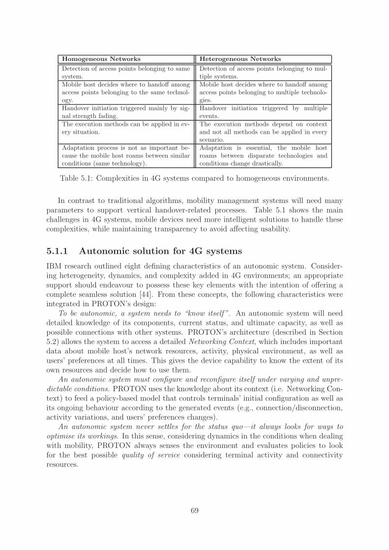
Homogeneous Networks Heterogeneous Networks
Detection of access points belonging to samesystem.
Detection of access points belonging to mul-tiple systems.
Mobile host decides where to handoff amongaccess points belonging to the same technol-ogy.
Mobile host decides where to handoff amongaccess points belonging to multiple technolo-gies.
Handover initiation triggered mainly by sig-nal strength fading.
Handover initiation triggered by multipleevents.
The execution methods can be applied in ev-ery situation.
The execution methods depend on contextand not all methods can be applied in everyscenario.
Adaptation process is not as important be-cause the mobile host roams between similarconditions (same technology).
Adaptation is essential, the mobile hostroams between disparate technologies andconditions change drastically.
Table 5.1: Complexities in 4G systems compared to homogeneous environments.
In contrast to traditional algorithms, mobility management systems will need manyparameters to support vertical handover-related processes. Table 5.1 shows the mainchallenges in 4G systems, mobile devices need more intelligent solutions to handle thesecomplexities, while maintaining transparency to avoid affecting usability.
5.1.1 Autonomic solution for 4G systems
IBM research outlined eight defining characteristics of an autonomic system. Consider-ing heterogeneity, dynamics, and complexity added in 4G environments; an appropriatesupport should endeavour to possess these key elements with the intention of offering acomplete seamless solution [44]. From these concepts, the following characteristics wereintegrated in PROTON’s design:
To be autonomic, a system needs to “know itself”. An autonomic system will needdetailed knowledge of its components, current status, and ultimate capacity, as well aspossible connections with other systems. PROTON’s architecture (described in Section5.2) allows the system to access a detailed Networking Context, which includes importantdata about mobile host’s network resources, activity, physical environment, as well asusers’ preferences at all times. This gives the device capability to know the extent of itsown resources and decide how to use them.
An autonomic system must configure and reconfigure itself under varying and unpre-dictable conditions. PROTON uses the knowledge about its context (i.e. Networking Con-text) to feed a policy-based model that controls terminals’ initial configuration as well asits ongoing behaviour according to the generated events (e.g., connection/disconnection,activity variations, and users’ preferences changes).
An autonomic system never settles for the status quo—it always looks for ways tooptimise its workings. In this sense, considering dynamics in the conditions when dealingwith mobility, PROTON always senses the environment and evaluates policies to lookfor the best possible quality of service considering terminal activity and connectivityresources.
69

An autonomic system knows its environment and context surrounding its activity, andacts accordingly. It is essential for PROTON to sense its context and produce events totrigger policies that drive mobile node’s behaviour.
An autonomic system cannot exist in a hermetic environment. In this sense, PRO-TON is compatible with the TCP/IP stack and it helps in the integration process ofheterogeneous networks, creating an open IP-based platform to access mobile services.
An autonomic system will anticipate the optimised resources needed while keeping itscomplexity hidden. PROTON offers seamless mobility support, coping with the complexityposed by 4G systems, hiding it from the users.
Currently, a system incorporating the eight elements [44] will be very difficult to build.However, the solution presented in this Chapter can be considered as an early attemptto critically examine such concepts. An autonomic system seems appropriate to tacklethe complexity posed by future integrated heterogeneous environments formed by diverseaccess networks and services, and a huge variety of mobile terminals interacting.
5.1.2 A novel approach
Using well-known entities such as finite state machines, this work proposes interpretationsand adaptations to the basic theory to suit the domain of policy-based systems. Policiesare modelled as finite state transducers that consume events, and a function called tautnessfunction is defined for the transitions.
The operations of finite state transducers are revised accordingly. In particular, deter-minisation and intersection operations have been adapted to mimic the modality conflictresolution process between policies. Also, it is shown how the composition of transducerscould be used to express constraints, e.g., the restriction of a particular subset of policiesaccording to the actual context.
To adapt this approach to resource-constraint mobile devices, all the tasks associatedwith the conflict resolution process can be done beforehand, and the computing of apolicy-evaluation is linear in the number of events, and independent of the number ofpolicies. This makes it possible to deal with the complexity and dynamics of 4G systemswhile keeping a light-weight solution.
The next section describes PROTON’s architecture that is divided into network- andhost-side components. Section 5.3 introduces the concept of Networking Context, defin-ing the three datasets that form it. Then, Section 5.4 explains the policy model basedon Finite State Transducers (FST). Section 5.5, describes the processes related to thegeneration, distribution, and evaluation of TFFSTs. Finally, Section 5.6 includes someremarks.
5.2 Architecture
PROTON components are divided into network-side and host-side components. Thereason for this is that because of the number of decisions required to fully support thehandover process, the raw policy set can get too complex to maintain within a limitedmobile device. However, the functionality still being completely based on the mobile host,only the highly demanding pre-processing tasks related to the policy evaluation model areplaced in the network—where computing constraints are much more relaxed (see Figure
70

(a) Network-side components (b) Host-side components
Figure 5.2: PROTON’s architecture.
5.2(a)). The host-side components are organised into a three-layered system: ContextManagement Layer, Policy Management Layer, and Enforcement Layer, which sit on topof layer 3 in the protocol stack. The network-side contains the components related to thespecification and distribution of the policies.
5.2.1 Network-side components
Those components that involve operator’s management or high computational cost arelocated in the network to minimise complexities at the mobile terminal. This is the caseof policy definition, storage, and conflict resolution. Network-side components are shownin Figure 5.2(a).
Policy Editor—To create the system policies, the operator must write them in a high-level policy specification language. Ponder was used as the high-level language becauseof its expressiveness and deployed tools. In particular, PROTON uses the Ponder PolicyEditor and its compiler [78] to create the first internal Java representation of the policies.
Policy Repository—The policy repository is implemented using a light-weight Di-rectory Access Protocol (LDAP) server, which intends to store system policies in theirhigh-level representation as well as in the internal Java representation.
Policy Translator—This component translates the policies specified in the Ponderlanguage [24] into the evaluation model described in Subsection 5.4.2.
Conflict Resolution Module (CRM)—The conflict resolution module builds thedeterministic Finite State Machine (FSM) modelling every active policy. The CRM per-forms two main tasks: (1) it combines the policies considering the system constraintsand (2) it resolves conflicts among those rules. During this task, all possible static anddynamic conflicts are foreseen. Therefore, the algorithms that are executed have a highcomputational cost. The main benefit of adding such overhead on the network-side is toavoid heavy tasks in the mobile device (usually a terminal with limited computationalpower and memory capacity). Furthermore, after resolving conflicts and constructing thedeterministic FSM, the mobile device can react quickly to incoming events.
71

Model Distribution Module (MDM)—Once all policies and constraints are com-bined in a TFFST, it is delivered to the mobile device and installed into its policy masterto drive its decisions. One TFFST is created and deployed for each mobility profile andthis module takes care of coding and transmitting the transducers to each mobile device.
5.2.2 Host-side components
Context Management Layer (CML)—This layer has two types of components re-sponsible for collecting Networking Context: Sentinels and Retrievers. The former areresponsible for collecting dynamic elements, and the latter manage static elements. Thereis a responsible object for each context element, and it has individual settings (e.g., pollingfrequency and local rules) depending on the complexity and dynamics of a particularfragment. For example, VelocitySentinel only polls the velocity every second due to theconstraints in the GPS receiver. The local rule (shown in Section 5.3) filters the col-lected data according to the current velocity and acceleration. Thus, not every reportedmeasurement generates an event.
Policy Management Layer (PML)—Responsible for the control and evaluation ofthe policies to drive the behaviour of the mobile device and it has the following elements:
Policy Master: This component acts as the Policy Decision Point (PDP) in the policysystem [69]. It receives events (e.g., Transition-Pedestrian produced by the VelocitySen-tinel) from the CML, and according to these inputs, it decides the possible actions toexecute, which are immediately sent to the Enforcement Layer.
Context-based profile selector: The fact that only a small portion of sensory input isrelevant under certain conditions is used to improve the performance of the system. Someinputs can generate special events (i.e. macro-events) which are then used by the selectorto load a profile that defines a valid subset of policies to evaluate, i.e. the appropriateTFFST . An example of a macro-event is velocity—if host speed is more than 90 km/hthe only active policies are those that produce an upward handover as an action. Thismeans that mobile users should never attempt to connect to a lower layer when movingat very high speeds.
TFFST Repository: The TFFSTs are produced in the network side, as mentionedin Subsection 5.2.1, and then deployed into the mobile device where they are kept inthe TFFST repository. Thereafter, the selected TFFST and its evaluation are decidedaccording to the events received from the CML.
Enforcement Layer (EL)—Formed by different Executors that are the Policy En-forcement Points (PEPs) of the system [69]. They are responsible for performing theactions that result from evaluating the TFFST. The EL connects with the lower lay-ers through a Control Interface (CI) that captures incoming router advertisements justbefore they reach the Mobile IPv6 module—prior to the handover procedure. The CIexecutes different scripts, which receive the selected interface as a parameter and outlinethe execution handover method.
Communication protocols—For the connection CML-PML and the communicationwithin the PML, a generic asynchronous notification service called Elvin is used [38]. Thisservice was designed as a middleware for distributed systems. However, many researchprojects have used Elvin due to its simplicity. Ponder uses this messaging service in itsframework, and it is use in the present system as well.
72

connectivitylink−layer
data flows
requirements
position
traffic
hostactivity
hostconnectivity
user profile
connectivityPH−layer
handoverexpected latency
network−layer connectivity
velocity
Mobile host
APs& BSslocation
locationhost
logical position
signal level
characteristicsnetwork QoS
app’s QoS
medium highlow
direction
high (policy model) low (local rules)(aggregated data)medium
DYNAMICS
COMPLEXITYRULE
Figure 5.3: Networking Context components.
5.3 Networking Context
Context is defined as any information sensed from the environment which may be usedto define the behaviour of a system. The effectiveness of PROTON’s assistance dependson three main tasks: accurate extraction, combination, and expression of unsteady mea-surements collected from the environment. These tasks are constrained by three factors:frequency in sensory capture, complexity in context fusion, and limited inference capabil-ity, respectively.
Since in a highly dynamic environment, the instability of the sensed data has a negativeimpact on the amount of information that can be extracted from a particular contextfragment, PROTON organises sensed data (i.e. Networking Context) into a three-levelhierarchy according to: dynamics of sensed data and complexity of the rules applied.This taxonomy results in the definition of three datasets, each of which has a particularcombination of rule complexity and component dynamics.Collected dataset—Every dynamic fragment gathered by a sentinel is part of thisdataset (high and medium dynamics components). Sentinels poll data from many differ-ent sources, and then filter it according to simple local rules that only affect the specificcontext element. The output of the collected dataset is smaller than the input, whichreduces the processing overhead in the mobile device.
For example, the local rule shown below corresponds to the VelocitySentinel, it filtersthe collected data (every second) according to current speed and the increment in veloc-ity. Therefore, this minimises processing and assures that generated events respond tomeaningful context changes.
73

void localRule(double currentVelocity) {double velDiff;
velDiff = Math.abs(currentVelocity - Host.getVelocity());
if (currentVelocity < PEDESTRIAN & velDiff > 2.5)
/*Generate event Transition-pedestrian*/event = new NamedEvent();
String[] params = new String[10];
params[0] = "Transition-Pedestrian";
params[1] = "double";
params[2] = Double.toString(velDiff);
event.HandleEvent(params);
if (currentVelocity < LOW AUTOMOBILE & velDiff > 5)
/*Generate event Transition-low-automobile*/if (currentVelocity < HIGH AUTOMOBILE & velDiff > 10)
/*Generate event Transition-high-automobile*/if (currentVelocity > HIGH AUTOMOBILE & velDiff > 20)
/*Generate event Transition-high-speed*/}
Aggregated dataset—It groups the filtered and retrieved information coming from theCML. The former is the output of the collected dataset after applying the correspondinglocal rules. The latter derives from the low-dynamic components, which are managed byRetrievers, e.g., user preferences retriever or application profile retriever.Networking Context dataset—It is a snapshot of the Aggregated and Collecteddatasets used by the Policy Master to select the path and evaluate the conditions inthe TFFST. The Networking Context allows the mobile host to have complete knowledgeof its resources, context, and activity at all times.
5.4 Policy model
Multi-mode mobile devices must be flexible and proactive to cope with dynamics andchanges in 4G systems. PROTON has to cover several aspects that derive from thispremise:
• The solution must include physical context (e.g., velocity and position).
• Adaptation must be supported in the system.
• PROTON must lead to unambiguous decisions in the shortest possible time.
After pondering these requirements, an effective approach to address the problem isa policy-based system to assist users in future mobile scenarios. Moreover, consideringthe constraints of dynamics and complexity, context was broken into simpler and moreintuitive fragments (as shown in Section 5.3) and policies were written using these elementsas conditions.
74

Thus, complexity is transferred to the combination of policies and decision-making,instead of having it in the individual rules. Therefore, using a policy-based system enableseasier tuning of the system’s behaviour. Employing cost functions to drive decisions canoften lead to static and over-complicated solutions, as the complexity is related to thenumber of parameters.
Furthermore, breaking down context into fragments allows us to use independentnormalisation functions for each element. This leads to a more accurate transformation ofthe parameters, while cost functions are more static. In conclusion, a policy-based systemis more flexible and can express more than a cost function.
The policy model uses Ponder [24] as a high-level language for policy specification.This framework is used to obtain an initial Java representation from the high-level policy.The Ponder language provides a common means of specifying policies that map ontovarious actors within a network. However, adaptations are required in order to use Ponderin a particular application as the implementation of an autonomic solution for 4G systems.
5.4.1 Policy specification
PROTON follows the Event-Condition-Action (ECA) paradigm where policies are rulesthat specify actions to be performed in response to predefined conditions, triggered byevents (see sample policy below).
Rule 1:
inst oblig /ProtonPolicies/Obligs/CheckupPolicy {on PhysicalConnection(nic);
subject /ProtonPMAs/HandoverPMA;
target t = /ProtonTargets/HandoverExecutor;
do t.networkSelectionEvent(nic);
when t.isLinked(nic);
}
The policy shown above, CheckupPolicy, is triggered when a new radio access interfaceis connected to the mobile host—the event PhysicalConnection is sent by the Attached-Sentinel. The policy target, HandoverExecutor, checks the connectivity in the networkinterface executing the method isLinked(nic). Then, when the new NIC (Network Inter-face Card) is linked the policy target sends an event to initiate the process of networkselection by executing the method networkSelectionEvent(nic). This high-level policy iscompiled into an initial Java representation and translated into TFFSTs.
5.4.2 An evaluation model based on FSTs
Finite state automata are classical computational devices used in a variety of large-scaleapplications. FSTs, in particular, are automata whose transitions are labelled with bothan input and an output label. They have been useful in a wide range of fields, but particu-larly in Natural Language Processing. This discipline makes intensive use of grammaticalrules, which are ambiguous by nature, and requires quick decisions based on those rules,in particular in fields such as speech recognition with major performance requirements.
75

Additionally, FSM-based solutions are typically light-weight. They can be imple-mented as arrays of states, transitions, and pointers among them without falling intocomputationally expensive management structures.
Policies are represented as deterministic transducers that are a category of transducerswithout ambiguities. This means that at any state of such transducers, only one outgoingarc has a label with a given symbol or class of symbols.
Deterministic transducers are computationally interesting because their computationorder does not depend on the size of the transducer, but rather only on the length of theinput since the computation consists of following the only possible path corresponding tothe input and writing consecutive output labels along the path [81].
For representing policies with FSTs the model presented in [6] was used (see AppendixB). It is based on a modification of predicate augmented FSTs [98], in which predicateswere replaced by a metric representing the relation between a policy and a given event.
A policy has a condition delimiting a region where a given event can or cannot lie.When such an event is inside two or more overlapping regions a modality conflict mayarise. The concern is to know how tautly a condition fits to an event instead of how farfrom the border it is. Thus, the preferred condition will be that which is the most tautaround the event under consideration.
In order to quantitatively represent the aforementioned tautness, a metric called Taut-ness Function is used, a real number in the interval [−1, 1] so that the more taut a conditionis, the closer its TF is to zero.
Definition 1 A Tautness Function associated with a condition c, denoted τc, establishesa mapping from E × C to the real interval [−1, 1] where:
• E is the set of possible network events or attempted actions,
• C is the set of policy conditions,
• τc(e) ∈ [−1 , 0 ) ⇔ e does not satisfy c,
• τc(e) ∈ (0 , 1 ] ⇔ e satisfies c,
• τc(e) = 1 ⇔ ∀f ∈ E , f satisfies c,
When the TF is modelling the condition part of the rule, in condition c the subject or anyother property of the condition such as temporal constraints, are included. In the samemanner, when the TF is modelling the action part of the rule, condition c includes thetarget or any property of the action.
To provide an intuitive example of TF, let us assume that one policy specifies wirelessinterfaces in general and another policy specifies IEEE 802.11b interface (a subset ofwireless interfaces). For an action attempted by a IEEE 802.11b interface, the secondpolicy should define a TF that is closer to 0 than the first policy. However, as with thedistance-to-a-policy concept, much more complicated expressions could be computed, forexample using the associated traffic types to the interface or the QoS characteristics.
76

Figure 5.4: Translation process.
Notice that in the TF definition only the general rules are stated, with which a TFshould comply. This non-specificity is deliberate, because how it should be implementedor how it maps events and conditions to real numbers should be decided in the contextof a specific policy-based system and technology. Thus, a TF is an abstraction layer oftechnology-dependent issues that allow us to work in a more general fashion.
In Subsection 5.5.6 some examples of how to compute TFs are shown. The mostoutstanding advantage of using TFs in PROTON is the capacity to define a different wayto evaluate each networking context fragment and combine them using the algebra forTFs, which defines the basic logic operators disjunction, conjunction and negation, plustwo new operators called tauter-than (→τ ) and as-taut-as (⇄τ ) specially formulated toexpress the concept of distance in the TFs (see detailed algebra definition in a summaryof [6] included in Appendix B). The definition of the transducers that use TFs to modelpolicies internally on the host side follows.
Definition 2 A Finite state transducer with tautness functions and identities M is atuple (Q, E, T, Π, S, F ) where:
• Q is a finite set of states,
• E is a set of symbols,
• T is a set of tautness functions over E.
• Π is a finite set of transitions Q × (T ∪ {ǫ}) × (T ∪ {ǫ}) × Q × {−1, 0, 1}2.
• S ⊆ Q is a set of start states.
• F ⊆ Q is a set of final states.
• For all transitions (p, d, r, q, 1) it must be the case that d = r 6= ǫ.
In the implementation, an extension of the above definition is used to let the transducerdeal with strings of events and actions in each transition. Policy rules are modelled usingTFFSTs, in which the incoming label represents the condition and the outgoing label theaction.
2The final component of a transition is an “identity flag” used to indicate when an incoming eventmust be replicated in the output.
77

Figure 5.5: TFFST model for the obligation in Rule 2.
5.4.3 Modelling policies with TFFSTs
To understand how the entities introduced before are used for modelling policies, it isfundamental to present how obligations and constraints are expressed. TFFSTs can alsomodel authorisations, prohibitions and dispensations [6], but the following two policytypes are expressive enough to deal with current PROTON requirements.
Obligations—An obligation is a rule expressing that when an event fulfils a particularcondition, a given action must be executed. It is represented as a transducer with a mainlink that has an event as the input and the action as the output. Typically, the incomingevent will report the occurrence of a fact and the outgoing event will order the executionof a given action. However, other combinations are possible as well, for instance, to beunobtrusive (as defined by [16]), the incoming event could be replicated in the output.
A clear view of the links between objects generated by Ponder tools and the TFFSTstructure is shown in Figure 5.4. The Ponder distribution [78] was modified to handle thenew TFFST structures and support the translation process.
Some actions can be conditioned on the occurrence of more than one event. Thisis the case of lazy switching handover method, in which after initiating the handover(receiving the NetworkSelected(nic) event) the action needs to be delayed—wait for theTimerOver(delay) event.
To express an action as a consequence of a set of events, e.g., Rule 2, a transducersuch as the one in Figure 5.5 is deployed.
Rule 2:
inst oblig /ProtonPolicies/Obligs/LazyHandover {on NetworkSelected(nic) → TimerOver(delay);
subject /ProtonPMAs/HandoverPMA;
target t = /ProtonTargets/HandoverExecutor;
do t.handoff(nic);
when t.isRAreceived(nic);
}
In the figures, the symbol “?” represents the TF associated with the all-event condi-tion while the “-” symbol represents set substraction and “ǫ” means a null event. TheNetworkSelected event is indicated using “ns”, the TimeOver event with “to”, the Fad-ingSignal event is “fs”, and the Handoff action uses the “ho” abbreviation. By convention,state 0 is initial and a double-circled state is final. Symbols “<” and “>” enclosing TFsin the labels, express identity between inputs and outputs (see [81]).
78

Figure 5.6: TFFST model for the constraint in Rule 3.
For the sake of simplicity, the fact that events can arrive without order is disregarded,and other possible events before and after the sequence of interest in the model are notincluded.
Constraints—Constraints are expressed using the composition TFFST operation in-cluded in Appendix B, an analogue operation to composition between functions. Afterall the obligations are represented in a single transducer, the transducer representingconstraints should be subsequently composed.
To see how constraints work, let us assume the InsertHysteresis example of Rule 3.If the model relies only on the plain policy, if a FadingSignal(nic) event occurs, the hostcan fall into the ping-pong effect. One possibility for avoiding this situation is to createthe following constraint:
Rule 3:
inst oblig /ProtonPolicies/Obligs/InsertHysteresis {on FadingSignal(nic);
subject /ProtonPMAs/HandoverPMA;
target t = /ProtonTargets/HandoverExecutor;
do t.ignoreFadingEvent(nic);
when t.hysteresisPeriod(time);
}
The transducer shown in Figure 5.6 represents this constraint. Computing the compo-sition of both transducers produces the solution shown in Figure 5.7, in which all possiblesystem responses are analysed a priori in the network side.
79

Figure 5.7: TFFST model for composition of rules 2 and 3.
Figure 5.8: Model distribution process.
5.5 Processes
This section describes the processes related to the policy model. Several tasks have to beperformed to generate, deploy, and evaluate the TFFST corresponding to a policy set (seeFigure 5.8). These tasks are: policy translation, conflict resolution, model distribution,context gathering, policy evaluation and tautness function computation.
5.5.1 Policy translation
Policy translation from high-level languages into internal policy evaluation models can be acomplex task that needs to be kept simple and performed on an ad-hoc basis in the system.As mentioned above, high-level policies built with the Ponder policy specification languagemust be translated into the internal policy evaluation model comprised of TFFSTs. Thetranslation process follows the principles presented in Subsection 5.4.3.
80

The main challenge of the deployment was the implementation of the TFs associatedwith the policy conditions. Considering the fact that the PROTON policy model is basedon the tools provided by Ponder, the approach chosen was to keep its object-orientedapproach using target and subject methods to compute TFs.
Thus, when target or subject methods are called to check a when clause, a corre-sponding method is called at the same time to assign a TF value instead of the booleanvalue that Ponder assigns to the condition. This method should be developed explic-itly, enabling the design of different TF computations depending on a specific parameter(for conditions represented by logical combinations of simple conditions, the TF algebraremains valid).
5.5.2 Conflict resolution
An advantage of using transducers to model policies is the rich set of operations available.It is possible to join, intersect, complement, compose and determinise transducers undercertain conditions. To build a TFFST that models a set of positive obligation policies, onefor each policy needs to be built and join them using the union operation. However, theunion of TFFSTs maintains ambiguities and contradictions. Therefore, determinisationand composition operations must be performed to eliminate these problems.
Determinisation transforms a TFFST into its deterministic and unambiguous ver-sion, in fact it also eliminates static conflicts between policies.
A TFFST M is deterministic if M has a single starting state, if there are no statesp, q ∈ Q such that (p, ǫ, x, q, i) ∈ Π, and if for every state p and event e there is at mostone transition (p, τd, x, q, i) such that τd(e) is positive.
If a TFFST is deterministic then the process of computing the output actions for agiven stream of events ω, can be implemented efficiently. This process is linear in ω,and independent of the size of the TFFST. The determinisation algorithm has two mainstages:
1. Eliminating apparent local conflicts: Local ambiguity may not be such if by analysingthe whole transducer, it is realised that only one path is possible until the final state.This is the case of the ambiguity shown in state 0 (see Figure 5.9(a)). Therefore,outputs are delayed as much as possible.
2. Resolving static conflicts: If it is not possible to delay output labels further, thesecond stage begins. A transition is created for each possible combination betweenpotentially conflicting conditions applying the following criterion: although an eventsatisfies two conditions, one of these conditions fits more tautly than the other. Theidea of tautness is represented by the Tautness Functions defined in Subsection 5.4.2,which can be used to compare orthogonal conditions.
In the output part of the transition, actions and events are arranged following theorder given by operators on the input. These operators are in fact part of the output.Later in the process these operators will be eliminated by the composition of transducersto apply the given constraints in the system. Figure 5.9(b) shows the transducer afterdeterminisation.
81

(a) Before determinisation (b) After determinisation
Figure 5.9: Determinisation process.
Composition eliminates semantic contradictions (i.e. dynamic conflicts) between theactions. This operation between transducers is equivalent to the composition of any otherbinary relation: R1 ◦ R2 = {(x, z) | (x, y) ∈ R1, (y, z) ∈ R2}.
Thus, the process can be understood as a chain of events where the events and actionsin the output of the first transducer are considered to be the input of the second one. Theadvantage is that the chain process is performed analytically in the network and not onthe mobile device.
If a TFFST is created, which replicates all input actions on the output except forthose patterns of actions not allowed on the system, and then the composition of thattransducer with the TFFST policy model is computed, and a transducer that enforcesactions without dynamic conflicts is obtained. This means actions that must not beperformed at the same time, for example two handovers, each one to a different network.
Consequently, conflict resolution is intrinsic to the model. This process not only buildsthe transducer that models the policies, but also eliminates ambiguities and contradictionsbetween those rules. The main steps are:
1. Compute the union of all transducers representing rights and obligations.
2. Substract the transducers representing prohibitions and dispensations.
3. Compose the resulting transducer for each constraint transducer.
4. Determinise the resulting transducer to solve conflicts.
Determinisation and composition operations are extensions to the algorithms devel-oped for predicate-augmented FSTs [98]. Baliosian et al. present a detailed explanationof these extensions in [6], and they were also included in Appendix B.
5.5.3 Model distribution
After policy translation, conflict resolution and TFFSTs composition, the final set ofTFFSTs for every mobility profile is built (everything so far happens on the networkside). Thereafter, the TFFSTs need to be sent to the repository in the mobile host.The Model Distribution Module together with the Policy Master, are responsible for theinstallation process.
82
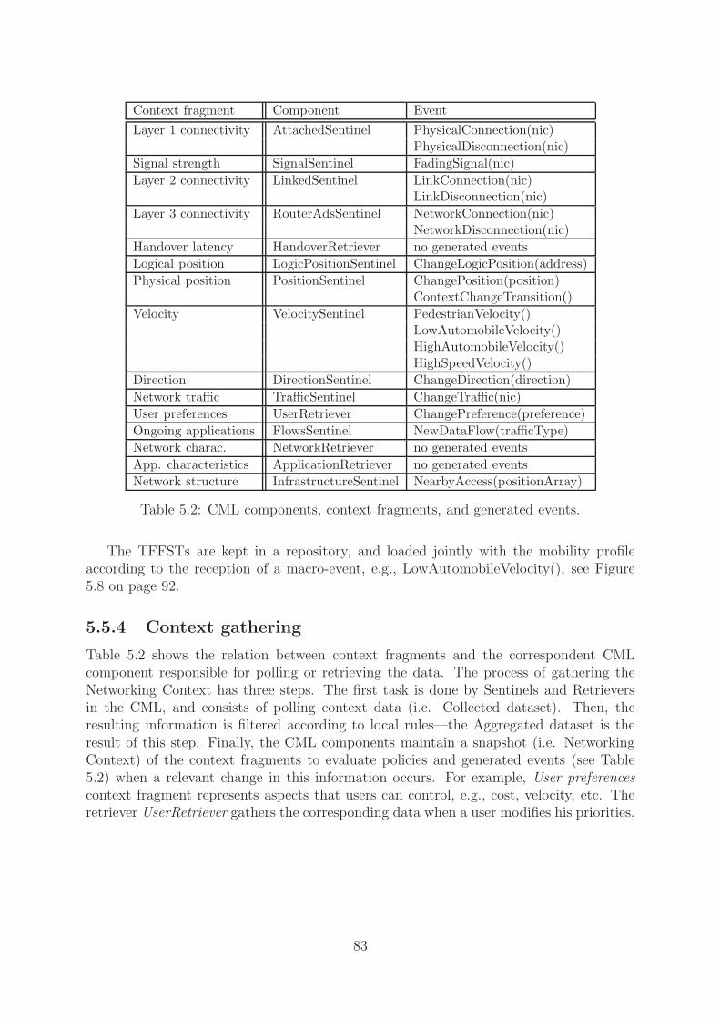
Context fragment Component Event
Layer 1 connectivity AttachedSentinel PhysicalConnection(nic)PhysicalDisconnection(nic)
Signal strength SignalSentinel FadingSignal(nic)
Layer 2 connectivity LinkedSentinel LinkConnection(nic)LinkDisconnection(nic)
Layer 3 connectivity RouterAdsSentinel NetworkConnection(nic)NetworkDisconnection(nic)
Handover latency HandoverRetriever no generated events
Logical position LogicPositionSentinel ChangeLogicPosition(address)
Physical position PositionSentinel ChangePosition(position)ContextChangeTransition()
Velocity VelocitySentinel PedestrianVelocity()LowAutomobileVelocity()HighAutomobileVelocity()HighSpeedVelocity()
Direction DirectionSentinel ChangeDirection(direction)
Network traffic TrafficSentinel ChangeTraffic(nic)
User preferences UserRetriever ChangePreference(preference)
Ongoing applications FlowsSentinel NewDataFlow(trafficType)
Network charac. NetworkRetriever no generated events
App. characteristics ApplicationRetriever no generated events
Network structure InfrastructureSentinel NearbyAccess(positionArray)
Table 5.2: CML components, context fragments, and generated events.
The TFFSTs are kept in a repository, and loaded jointly with the mobility profileaccording to the reception of a macro-event, e.g., LowAutomobileVelocity(), see Figure5.8 on page 92.
5.5.4 Context gathering
Table 5.2 shows the relation between context fragments and the correspondent CMLcomponent responsible for polling or retrieving the data. The process of gathering theNetworking Context has three steps. The first task is done by Sentinels and Retrieversin the CML, and consists of polling context data (i.e. Collected dataset). Then, theresulting information is filtered according to local rules—the Aggregated dataset is theresult of this step. Finally, the CML components maintain a snapshot (i.e. NetworkingContext) of the context fragments to evaluate policies and generated events (see Table5.2) when a relevant change in this information occurs. For example, User preferencescontext fragment represents aspects that users can control, e.g., cost, velocity, etc. Theretriever UserRetriever gathers the corresponding data when a user modifies his priorities.
83

5.5.5 Policy evaluation
Policy evaluation occurs in the TFFST model. As mentioned, the computational load ofdeterministic transducers does not depend on the size of the transducer but rather onlyon the length of the input. This is possible because the computation consists of followingthe only possible path corresponding to the input represented by an epoch or window ofevents, which are considered simultaneous for the purpose of detecting dynamic conflicts.
When evaluating the epoch, the transducer performs two tasks: it checks the currentepoch and decides if it contains a relevant event pattern in order to decide whether ornot to accept it; then it produces a sequence of actions for every accepted epoch, whichis sent to the Policy Enforcement component.
5.5.6 Tautness function computation
A fundamental process in the distribution of TFFST models is the appropriate computa-tion of tautness functions. The prototype handles each parameter individually with thecommon idea of expressing the probability of a condition. For example when computinga condition (related to bandwidth) such as:
...when t.effectiveBW([nic A]) <t.effectiveBW([nic B]);...
If nic A is connected to a hotspot and nic B uses Vodafone’s GSM/GPRS network,considering the maximum data rates presented in Table 3.1, and assuming their valueshave uniform distributions, when the condition to true is evaluated, its tautness functionis:
144kb/s
11Mb/s × 1000× 0.5 = 0.00654
This function shows the conditional probability of occurrence for a handover policy,based on bandwidth. The probability to handoff from a cellular system to a hotspot is onehalf. However, this value is affected by the difference in bandwidth. The function showsthat the probability of the maximum bandwidth of a GPRS network (144 kb/s) beingbigger than the bandwidth of a hotspot (11 Mb/s) is very small. In the cases where thishappens, the mobile node would handoff from the hotspot (without loosing connectivity)to the cellular system.
A value as close to zero as this one means a very strong condition. Hence, it is veryunlikely that this situation will occur and the manager must have had a very good reasonto specify a policy with this condition. Therefore, during the determinisation processthis condition will have a high priority. Nevertheless, at runtime each TF value will beevaluated according to the user profile.
84
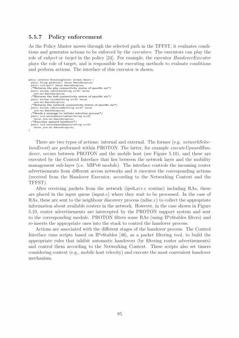
5.5.7 Policy enforcement
As the Policy Master moves through the selected path in the TFFST, it evaluates condi-tions and generates actions to be enforced by the executors. The executors can play therole of subject or target in the policy [24]. For example, the executor HandoverExecutorplays the role of target, and is responsible for executing methods to evaluate conditionsand perform actions. The interface of this executor is shown.
public interface NetworkingContext extends Remote {public String getStatus() throws RemoteException;
public void quit() throws RemoteException;
/*Returns the phy connectivity status of specific nic*/public boolean isAttached(String nicID) throws
java.rmi.RemoteException;
/*Returns the link connectivity status of specific nic*/public boolean isLinked(String nicID) throws
java.rmi.RemoteException;
/*Returns the network connectivity status of specific nic*/public boolean isReceivedRA(String nicID) throws
java.rmi.RemoteException;
/*Sends a message to initiate selection process*/public void networkSelectionEvent(String nicID)
throws java.rmi.RemoteException;
/*Executes upward handover*/public void executeUpwardHandover(String nicID)
throws java.rmi.RemoteException;
}
There are two types of actions: internal and external. The former (e.g. networkSelec-tionEvent) are performed within PROTON. The latter, for example executeUpwardHan-dover, occurs between PROTON and the mobile host (see Figure 5.10), and these areexecuted by the Control Interface that lies between the network layer and the mobilitymanagement sub-layer (i.e. MIPv6 module). The interface controls the incoming routeradvertisements from different access networks and it executes the corresponding actions(received from the Handover Executor, according to the Networking Context and theTFFST).
After receiving packets from the network (ipv6 rcv.c routine) including RAs, theseare placed in the input queue (input.c) where they wait to be processed. In the case ofRAs, these are sent to the neighbour discovery process (ndisc.c) to collect the appropriateinformation about available routers in the network. However, in the case shown in Figure5.10, router advertisements are intercepted by the PROTON support system and sentto the corresponding module. PROTON filters some RAs (using IPv6tables filters) andre-inserts the appropriate ones into the stack to control the handover process.
Actions are associated with the different stages of the handover process. The ControlInterface runs scripts based on IPv6tables [46], as a packet filtering tool, to build theappropriate rules that inhibit automatic handovers (by filtering router advertisements)and control them according to the Networking Context. These scripts also set timersconsidering context (e.g., mobile host velocity) and execute the most convenient handovermechanism.
85

4G Communication system
LAN GPRS 3GWLAN satellite4G Communication system
LAN GPRS 3GWLAN satellite
ipv6_rcv.c
ipv6_input.c
ROUTING
mipv6.c
ipv6_output
ROUTING
ipv6_fw.c
ipv6_xmit.c
ndisc.c
neighbourdiscovery
routerhookads
handover executor
(userspace)
PROTON SUPPORT
CONTROLINTERFACE
SYSTEM
Figure 5.10: Handover Executor implementation.
5.6 Remarks
In this Chapter, PROTON was presented, a policy-based system to support multi-modedevices. Motivation behind PROTON stems from the fact that future devices will havemulti-mode capability for connecting to different wireless networks. It is demonstratedhow PROTON can address several issues of future networking, and how it can cope withcomplexity and dynamics intrinsic to future environments.
As far as I know, PROTON is the first policy-based system that attempts to offercomplete mobility support for 4G mobile users. These heterogeneous environments posechallenges that remain open. Using a policy model based on TFFSTs, PROTON helpsusers in many decisions while hiding the added complexities.
It is also shown that concepts from autonomic computing can be applied to the designof novel solutions that brings us closer to the answer of open networking challenges suchas seamless roaming among heterogeneous technologies.
This project consolidates the idea of building the policy evaluation model on thenetwork, to enable devices with the capability to deal with complexities while keeping apowerful light-weight solution.
The Networking Context dataset presented is rich enough to allow well-informed de-cisions while roaming. However, the possibility of using a rich set in such a dynamicenvironment is empowered by the idea of having three levels of information according tothe dynamics of data elements.
86

PROTON’s architecture also reflects the concern of dealing with constraint devices,particularly in a constantly-changing environment. This is the main drive behind dividingPROTON into network- and host-side components. Every module that demands intensivecomputation work or high storage capacity is located in the network.
The mobile device deals, exclusively, with the evaluation of TFFSTs, a task that doesnot require much processing. Via the application of novel algorithms for the specificationand translation of policies, conflict resolution, and TFFST distribution and installation,I have implemented a complete system that supports seamless roaming in upcoming per-vasive networking environments, while representing a light-weight solution that is easy todeploy.
Powerful and more intelligent solutions are needed to support inter-networking in fu-ture communication systems. However, mobile devices and wireless environments willalways exhibit strong limitations in terms of memory capacity, processing power, andstability. Hence, the prior resolution of conflicts and TFFST distribution is a very appro-priate approach to overcome these constraints.
PROTON has demonstrated the potential of merging concepts of autonomic com-puting with the design and implementation of a policy-based system, together with anovel evaluation model and efficient conflict-resolution algorithms. The result: a solutionthat offers full mobility support, hides complexities, enables smart decision-making whileroaming, and deals with the intrinsic constraints of 4G environments.
87

88
Chapter 6
Evaluation
The deployment of a policy-based system such as PROTON in constrained devices suchas those used in mobile environments, represented a huge challenge with clear trade-offsbetween costs added into the network side, the link, and the end devices. Hence, a novelapproach was proposed to extend the advantages of policy-based solutions beyond thewired world; it includes all the benefits of complex policy-based systems, but within asimple abstraction deployable in the wireless world.
To evaluate this work, its most relevant aspects were examined. First, using theLCE-CL testbed, a test case was simulated to demonstrate the usefulness of the system.PROTON’s main goal is to improve users’ connectivity and thus augment their produc-tivity. It is important to ensure that the system takes appropriate decisions according toits purpose. Therefore, this was evaluated during the experiment; the outcome is reportedin Section 6.1.
Second, the departure from a complex policy-based system, centralised in powerfulcomputing devices, to a simple decision-making structure, distributable to mobile ter-minals, mandates low resource usage and overheads in terms of computational power,memory, and bandwidth. These were measured during the experiments, and the resultsare presented in Section 6.2.
Third, Section 6.3 discusses how feasible it is to deploy PROTON in a typical mobilephone examining the main constraints: the out-degree of TFFSTs and the number oftransitions (which determine the TFFSTs’ size) and the number of events.
Fourth, Section 6.4 shows the scalability of the system when increasing the threeelements that bound the complexity of a policy: number of events, context fragments(conditions), and actions.
Finally, a taxonomy of mobility management systems derived from a comparison be-tween PROTON and other similar systems is presented in Section 6.5, emphasising thecharacteristics that lead to a good solution for mobility management. In addition, thepractical advantages of PROTON are summarised at the end of this chapter.
89

user connected to LAN
starts data transfer
receivesNetworkDisconnection(eth0)
receivesContextChangeTransition(gps)
receivesNetworkConnection(hotspot)
Pedestrian Mobility Profile
High Speed Mobility Profile
Low Speed Mobility Profile
macro-eventHighAutomobileVelocity()
constraintNo DownwardHandover
macro-eventLowAutomobileVelocity()
receivesFaddingSignal(hotspot)
receivesNetworkConnection(hotspot)
time (s)
sequence number time sequence graph
receivesNetworkDisconnection(hotspot)
Figure 6.1: Testing PROTON in a simulated scenario.
6.1 Test case
Imagine Alice in her office using her PROTON-enabled laptop; she starts downloading alarge amount of data that she needs for an important business lunch in London’s financialdistrict. She decides to leave her office immediately and continue downloading the data on-the-move. When Alice disconnects her laptop from the local network, the first PROTONevent is generated: NetworkDisconnection(eth0). This initiates the policy evaluation, thelaptop connects to the Wi-Fi network available in the building and continues downloadingthe data without any disruptions to the connection.
When she leaves the building, the PositionSentinel cannot read the data from the in-door location system—e.g., the bat system [105]—hence generating the second event: Con-textChangeTransition(gps). The mobile device begins determining its location using itsGPS receiver, and connects to an available cellular system (e.g., Vodafone’s GSM/GPRSnetwork). As Alice approaches her car, PROTON detects a nearby hotspot and generatesthe event NetworkConnection(hotspot) and evaluates the appropriate set of policies todecide how to use this broadband network.
She starts driving on the highway towards the city centre, and as she drives accelerationis detected by GPS-receiver. This is monitored by PROTON that generates a macro-event: HighAutomobileVelocity()—this triggers the selection of a different mobility profilethat is loaded in the device. PROTON connects to the GPRS network when hotspotconnectivity is lost, and while Alice is driving on the highway no downward handoversare allowed. This is because of the constraint NoDownwardHandover specified in theHighAutomobileVelocity mobility profile and built into the corresponding TFFST. Thus,she stays connected to the GPRS system.
90

She reduces speed as she reaches congested traffic areas in the city centre. Thissituation is detected by the VelocitySentinel and the macro-event LowAutomobileVelocity()is sent. Another mobility profile is loaded. The NetworkConnection(hotspot) event isreceived: PROTON evaluates the TFFST and decides to continue with the data transferusing an available hotspot. A few minutes later, the signal from the current access pointstarts fading and the event FadingSignal(hotspot) is generated.
PROTON changes its attachment point without any disruption; it uses the mostappropriate execution method and the optimal initiation time, and adapts itself to thenew QoS conditions exploiting its policy model and Networking Context dataset. Alicearrives at her final destination, and PROTON connects to the restaurant’s hotspot todownload the last few bits of data, while Alice starts her meeting.
PROTON’s usefulness was tested through simulated cases such as the example de-scribed; these show how the system, autonomously, executes appropriate actions to en-hance users’ mobile experience. For example, Figure 6.1 shows how typical networkactivities would be efficiently performed in a real 4G system when using PROTON.
The system was installed in a multi-mode device (a Toshiba Satellite laptop) thatcan access multiple access networks, and a sequence of events was produced. This se-quence triggered the evaluation of a subset of policies and generated the execution of thecorresponding actions.
6.1.1 Test case inputs
For the test cases, several event sequences were generated. Due to the lack of experi-mental data to define the probability of each event occurring, these values were decidedconsidering the following assumptions:
• Macro-events are “special” events generated when there is a significant variation inan specific (marked) context fragment (e.g., velocity). Thus, these events are lesslikely to occur than normal events.
• The network-dependent events (e.g., NetworkDisconnection(nic), FadingSignal(nic),etc.) are most likely to occur because of the huge variety of access networks expectedto make up forthcoming 4G systems, and these represent the most probable ofevents.
• Changes in physical context such as position and velocity (collected dataset) are fil-tered (aggregated dataset) and despite the high frequency of variation, these changesdo not generate events particularly often.
Based on these principles, three probability levels are used during the generation ofevent sequences: low, medium, and high. The probability of a network-dependent eventis P (End) = 5/10 (high probability).
91

For a macro-event P (Em) = 3/10 (medium probability), and for any other eventP (E) = 2/10 (low probability). Then, depending on the event generated, two differentprocesses can be triggered: when a macro-event occurs the model distribution process isstarted and for any other event the policy evaluation process is performed.
6.1.2 Case discussion
During the above test case a sequence of events was generated and the events sent fromthe CML to the PML. For every situation, the event generation was successful and thePM evaluated the corresponding TFFST. To finish the process, the appropriate actionswere triggered and executed by the Handover Executor. The model distribution processwas also tested by generating a pair of macro-events. The first macro-event triggered thereplacement of the current set of policies with a new TFFST, and the second caused theoriginal TFFST to be reloaded—the “old” TFFST was already in the mobile device whilethe “new” transducer was requested from the network side.
The above scenario was simulated using the LCE-CL testbed and the results obtainedfrom an analysis of the collected traces. The estimated average throughput shows thatuser experience improved when using PROTON. Moreover, when devices are not enhancedwith this system, transparent mobility is not possible, terminals would be subject of blackouts in connectivity, and users would not be capable of continuing their tasks withoutsuffering network disconnections.
System performance is enhanced when using PROTON because mobile devices can ex-ploit “ubiquitous” network access. In addition, seamless roaming between heterogeneousnetworks is enabled and the impact of mobility on the networking stack minimised.
6.2 Resource usage and overheads
To transform a typical network-centric policy-based system into a terminal-based supportsolution represents a clear trade off between costs in the network and in the end device.The complete knowledge about associated costs for each and every process is fundamen-tal to evaluate the applicability, feasibility, and scalability of the system. This sectioncalculates these costs and overheads in terms of computing resources and time. All theexperiments were performed on the LCE-CL testbed for a complete description of theexperimental platform and the computational equipment used, refer to Chapter 3.
The decision that determined the location of each process (network or device) wasmade in the early stages of the system’s design. The main motivation behind such anarchitecture lies in the distinction between light policy-related processes such as TFFSTevaluation and policy enforcement, and heavy processes such as TFFST creation, that donot need to be co-located in the mobile device.
In order to deploy a policy-based solution in a resource-limited environment such as a4G system, it is necessary to shift processes with high computational cost from the mobiledevice to the network.
Figure 6.2 shows the location for each process and its computational costs. The archi-tecture supports the dissociation of the individual processes: complexity on the networkside and complexity involved in policy evaluation and enforcement on the host side. Theformer is of a considerably higher degree and involves policy selection and translation,
92

Context collection
Event generation
Policy evaluation
Policy enforcement
Σi=0
n
Σn
i=0
T( ex ) = t( a) i
T( c ) = T ( a ) + T ( t ) + T ( cr )
TFFST construction
Policydatabase
Policy translation
Conflict resolution
T( d )= P( s ) / BW + T( s )
Load/store TFFST
TFFST computation
iMem = TFFST(size)
T( e )= T ( g ) + T (tx)
TFFST transfer
T(cc)= T(cc1)+T(cc2)+T(f)+T(u)
TFFST distribution
T(eval) = E X T(trans) X Max (D )
Figure 6.2: Resource usage.
and conflict resolution algorithms. As stated previously, these tasks are accomplished bypowerful, centralised devices in the network, thus, they are not seen as an applicabilityissue.
6.2.1 TFFST construction
The construction of deployable abstractions of the policy model (TFFSTs) is done in thenetwork side. The total processing time required to build one transducer (Tc) depends onthe capacities of the computing device and includes: selecting and loading the policies fromthe central policy database (Ta), translating the policy set to an internal representation ortransducer (Tt), and resolving potential conflicts between the chosen policies (Tcr). Theapplication of these algorithms has a high computational cost and it is done a priori, inthe network, to the TFFST distribution.
6.2.2 TFFST distribution
The first deployment issue arises from the TFFST distribution process. After the comple-tion of the TFFST construction process, the created transducers need to be transferredto the mobile terminals. The cost of this process is twofold. The first overhead is causedby the time needed to transfer the TFFSTs to the MN using a particular access tech-nology (Ps/BW , where Ps represents policy size and BW access technology bandwidth).Additionally, the TFFST management in the mobile terminal causes the second overhead(Ts).
93

Description Ps[kB] BW[kb/s] Ts[s] (Mem%) Td[s]
Nokia 3300 connected to a GPRS accessnetwork, and storing the mobility profilesin internal memory (4.5 MB).
466 52.8 0(10%) 70.6
Nokia 3300 connected to a WLAN accessnetwork, and storing the mobility profilesin internal memory (4.5 MB).
466 600 0(10%) 6.2
Nokia 6670 connected to a GPRS accessnetwork, and storing the mobility profilesin internal memory (8M B).
466 52.8 0(6%) 70.6
Nokia 3300 connected to a GPRS accessnetwork, and storing the mobility profilesin external memory (64M B).
466 52.8 2.1(1%) 72.7
Table 6.1: Aggressive distribution policy.
The main constraints in this process are: limited memory in mobile devices, limitedbandwidth in wireless technologies, and limited time to operate the system. After ob-serving the costs and constraints in the TFFST distribution, three different strategies areproposed to control the process.
One strategy could be to download all the appropriate TFFSTs when the mobile deviceis powered on. For the scenario under consideration it means transferring 466 KB (seeTable 6.1), and depending on the technology used it could take 6 s if the MN is connectedto a WLAN, and up to 70 s for the case of a “4+1” GPRS link. 1 In addition, a delayof approximately 3 s needs to be assumed to manage the TFFSTs in the mobile device(load and store the transducers). 2
This strategy may be convenient when storage space is not an issue in the mobiledevice. The main disadvantages of this technique are the intensive use of the link duringinitialisation and the delay in the beginning to start operating. From the additionalexamples shown in Table 6.1 it is evident that this aggressive strategy would effectivelywork when the mobile device has enough memory and it is connected to a fast accessnetwork.
However, this is not always the case, as some mobile devices have less memory andmobility management support is only one of many activities demanding storage space inmodern phones. Hence, a conservative strategy could be applied in these situations; theMN downloads TFFSTs on-demand and only in response to a macro-event.
This second strategy does not depend on the total number of TFFSTs (total size).However, it is limited by the frequency with which macro-events occur and the individualTFFST’s size. Table 6.2 shows the worst case: a large-size TFFST(pedestrian mobilityprofile) downloaded using a slow access network(GPRS).
The conservative technique could be seen as appropriate for small-memory devices,very common in mobile environments. However there would be delays of approximately5s and up to 15 seconds every time that a macro-event occurs, during which the MNwould not be able to function properly. Therefore, the downloading of TFFSTs shouldbe minimised by modifying the conservative strategy.
1The average effective bandwidth considered for this analysis was the AirCard750 “4+1” phonecard,resulting in 52.8 kb/s for the downlink connection.
2For a Nokia mobile phone, the read/write latency to external memory is 1400 b/s.
94
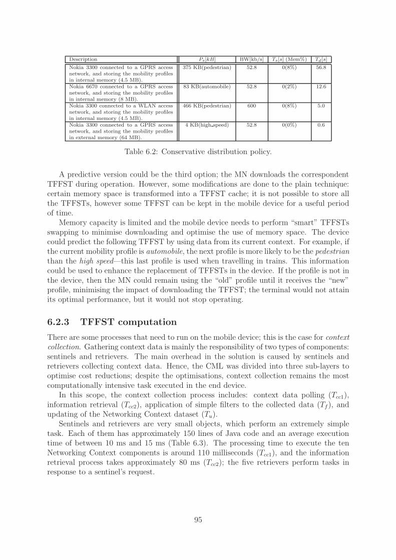
Description Ps[kB] BW[kb/s] Ts[s] (Mem%) Td[s]
Nokia 3300 connected to a GPRS accessnetwork, and storing the mobility profilesin internal memory (4.5 MB).
375 KB(pedestrian) 52.8 0(8%) 56.8
Nokia 6670 connected to a GPRS accessnetwork, and storing the mobility profilesin internal memory (8 MB).
83 KB(automobile) 52.8 0(2%) 12.6
Nokia 3300 connected to a WLAN accessnetwork, and storing the mobility profilesin internal memory (4.5 MB).
466 KB(pedestrian) 600 0(8%) 5.0
Nokia 3300 connected to a GPRS accessnetwork, and storing the mobility profilesin external memory (64 MB).
4 KB(high speed) 52.8 0(0%) 0.6
Table 6.2: Conservative distribution policy.
A predictive version could be the third option; the MN downloads the correspondentTFFST during operation. However, some modifications are done to the plain technique:certain memory space is transformed into a TFFST cache; it is not possible to store allthe TFFSTs, however some TFFST can be kept in the mobile device for a useful periodof time.
Memory capacity is limited and the mobile device needs to perform “smart” TFFSTsswapping to minimise downloading and optimise the use of memory space. The devicecould predict the following TFFST by using data from its current context. For example, ifthe current mobility profile is automobile, the next profile is more likely to be the pedestrianthan the high speed—this last profile is used when travelling in trains. This informationcould be used to enhance the replacement of TFFSTs in the device. If the profile is not inthe device, then the MN could remain using the “old” profile until it receives the “new”profile, minimising the impact of downloading the TFFST; the terminal would not attainits optimal performance, but it would not stop operating.
6.2.3 TFFST computation
There are some processes that need to run on the mobile device; this is the case for contextcollection. Gathering context data is mainly the responsibility of two types of components:sentinels and retrievers. The main overhead in the solution is caused by sentinels andretrievers collecting context data. Hence, the CML was divided into three sub-layers tooptimise cost reductions; despite the optimisations, context collection remains the mostcomputationally intensive task executed in the end device.
In this scope, the context collection process includes: context data polling (Tcc1),information retrieval (Tcc2), application of simple filters to the collected data (Tf), andupdating of the Networking Context dataset (Tu).
Sentinels and retrievers are very small objects, which perform an extremely simpletask. Each of them has approximately 150 lines of Java code and an average executiontime of between 10 ms and 15 ms (Table 6.3). The processing time to execute the tenNetworking Context components is around 110 milliseconds (Tcc1), and the informationretrieval process takes approximately 80 ms (Tcc2); the five retrievers perform tasks inresponse to a sentinel’s request.
95

Context data Tcc[ms] (polling)Tcc1[ms]
Layer 1 connectivity 27 5Signal strength 32 14Layer 2 connectivity 29 5Layer 3 connectivity 38 14Handover latency 32 10Logical position 43 16Physical position 73 19Velocity 9 4Direction 22 4Network traffic 45 17User profile 5 N/AOngoing applications 14 N/ANetwork characteristics 22 N/AApplication characteristics 16 N/ANetwork structure 18 N/A
Table 6.3: Processing time for three-level and polling tasks.
Additionally, several filters are applied to the collected data to form the aggregateddataset (Tf) and the Networking Context dataset is updated; these two tasks can take upto 200 ms. The total time taken for the context collection process to complete is between250 ms and 300 ms (left column in Figure 6.3, Tcc). It is critical for performance to definehow often the CML updates the Networking Context, and this frequency also depends onthe velocity of the terminal itself.
As updating the Networking Context dataset takes between 200 ms and 300 ms, itcannot be refreshed at a frequency higher than 5Hz. This is enough for most of themobility scenarios (e.g., pedestrians, cars, trains, and aeroplanes) under the assumptionthat as the MN velocity increases, less context data is relevant.
Figure 6.3 shows the distances that a mobile would have travelled between two updates,varying velocity and update frequency. For example, when a pedestrian carrying a laptopmoves, context changes will be detected every 4 m (for an update frequency of 0.25 Hz). AMN travelling at 120 km/h, and spending 200 ms collecting data, would observe contextchanges approximately every 33 m.
The complete execution of these tasks can consume a lot of processing time in suchresource constrained devices, and it will not be possible to have high update frequencies,therefore high-speed nodes would miss important context changes. However, as the veloc-ity increases the amount of relevant context data decreases—fewer sentinels and retrieversare examined—and small variations in the context fragments lose relevance for the policymodel (fewer events are generated).
Along with context collection, there are other processes taking place on the host:event generation, policy evaluation, and policy execution. As explained previously, inSection 5.3, not all the context changes generate events, in order to reduce processingload. However, if an event is generated, then the process initiates when the correspondentsentinel or retriever constructs a valid message [32], which is sent to the event-consumer,i.e. the Policy Master. This whole process takes around 150 ms, from the construction of
96

Figure 6.3: Travelled distances between updates.
Mobility profile Max. out-degree Evaluation time (ms)
Pedestrian 3165 396Automobile 316 108
High Automobile 39 24High Speed 39 24
Table 6.4: Run-time performance for policy evaluation.
the message to the instant it is consumed by the Policy Master.Following the reception of an event, the Policy Master initiates the policy evaluation
process. The evaluation time is linear with input length and it does not depend on thesize of the transducer. However, the final evaluation time does depend on the maximumnumber of outgoing transitions belonging to any state in the transducer (transducer’sout-degree. 3)
In each stage of the deterministic transducer evaluation, the valid transition must beselected from among all the transitions associated with the state. Thus, the maximumevaluation time for a set of events is: E × Ttrans × Maxi (Di), where E is the number ofevents inputed, Ttrans is the time of evaluating one transition’s TF and Di the number ofoutgoing transitions for the state i.
Table 6.4 shows the evaluation time for an input of two events using each of themobility profiles. The out-degree of the mobility-profile’s TFFST is also shown.
The outcome of the policy evaluation process (actions) must occur during the handoverperiod. Table 4.1 shows latencies measurements for the most common inter-network
3Maximum out-degree among all states in the TFFST. By definition, the number of outward directedgraph edges from a given graph vertex in a directed graph [60].
97

handovers. The policy enforcement process and corresponding actions should take placewithin this interval. According to the experiments, the Handover Executor needs toperform an average of five actions to control the complete roaming process. The possibleactions include: IPv6tables rule instantiation, modifications to the routing table, networkinterface control, and triggering other policies.
6.3 Feasibility of deployment
A possible disadvantage, during deployment, of using TFFSTs is the high complexityof their algorithms and the size of the final transducer. By utilising heuristics in PRO-TON strategies, the internal TFFST model size and complexity have been kept withinacceptable limits.
As described in Section 5.3, not every context fragment matters in every situation.In PROTON, important fragments are selected according to mobility profiles. Hence, atransducer is built for each profile, reducing the maximum size of each TFFST, avoidingprocessing overhead and minimising storage space in the mobile device.
The TFFST selection process, on the host side, can be seen as hot-reprogrammingof the device to optimise its behaviour dependent on the scenario. The current versionimplements four different mobility profiles according to the velocity context fragment thatproduces the following macro-events: PedestrianVelocity, LowAutomobileVelocity, High-AutomobileVelocity, and HighSpeedVelocity. Every time that one of these macro-events isgenerated, the corresponding mobility profile is loaded.
Experiments in different scenarios showed that the number of transitions for eachmobility profile’s TFFST was dependent on the quantity of relevant context fragments,possible events, and applied constraints. These variations correspond to the followingfacts:
• At lower velocities more context fragments can be considered in taking decisions,increasing the number of transitions.
• At the highest velocities more constraints can be applied to the policy model, re-ducing the number of transitions.
• At higher velocities, fewer events are relevant to making decisions, decreasing thenumber of transitions.
The number of transitions required for TFFSTs representing per-mobility-profile poli-cies was significantly smaller than per-device policies, because the conditional part ofthe policy is more specific (fewer context fragments are considered) and the number ofcombinations is lower.
98

Figure 6.4: Maximum number of transition for each mobility profile.
The maximum size of a single, per-mobility-profile, TFFST is reduced by severalconstraints [28]. Firstly, in FST terminology, the size of an input string is limited bynot allowing symbols, i.e. events, to repeat. Thus a maximum number of strings for analphabet of m symbols is given by:
m∑
i=1
Cmi
where Cmi represents all the possible combinations for a particular set of conditions.
As the maximum length of each of the strings is m, an upper bound on the number oftransitions in a TFFST is given by:
m ×m∑
i=1
Cmi
For example, the full size of a moderately simple policy such as the TFFST presentedin Figure 5.6 was 15 transitions and 8 states. Figure 6.4 shows the maximum numberof transitions for each mobility profile, which are formed by multiple policies. The ex-periments showed that the number of transitions for pedestrian velocities is much higher(around 9000 transitions per TFFST) compared to other mobility profiles: for automobilevelocity the number is around 2000 and approximately 100 for high speed profiles (Figure6.4). However, these numbers do not increase computational complexity, only the size ofthe TFFST.
Computation complexity of evaluation in deterministic FSTs, and thus TFFSTs, doesnot depend on the size of the transducer but on the length of the input (m). Hence, interms of computing cost and processing time the most relevant dimension of a TFFST isits out-degree, as a valid transition has to be selected out of all available transitions. Theout-degree is the maximum number of outgoing transitions belonging to one particularstate of the transducer. Figure 6.5 shows the maximum out-degree for different numberof conditions, which is the same as the order of the determinisation algorithm. An upperbound on the magnitude of the cost of evaluating a node i.e. state, is given by:
99

0
5000
10000
15000
20000
25000
30000
35000
1 2 3 4 5 6 7 8 9 10 11 12 13 14 15
Number of conditions
Max
imum
out
-deg
ree
Figure 6.5: Upper bound on the out-degree for different numbers of conditions.
O
(n∑
i=1
Cni
)
where n is the number of conditions that may be fulfilled at the same time, i.e. in a singleevent. Conditions as used in this context correspond to “when” statements in Ponder.This maximum bound obeys the fact that after applying the determinisation algorithmevery exclusive conditions’ combination must be computed.
The lower bound is simply linear with the number of conditions:
O (n)
The number of conditions was significantly reduced by grouping the policies in mobilityprofiles and defining macro-events. Other than any static conflicts, it is expected thatTFFSTs will be highly deterministic, inherently bringing the order of their states close toO(n) in the average case.
TFFST evaluation complexity will be impacted by complexity of the tautness functionsused to discriminate between actions, which are deployment-specific and should be tailoredto specific resource capacities of client devices.
Also relevant to the evaluation of the feasibility of deployment is the memory capacityneeded to allocate TFFSTs in mobile devices. Transducers’ transitions are implementedas simple objects with an average size of 40 bytes each. A TFFST can be seen as anarray of transitions that in the worst scenario (pedestrian profile) would require 332 KBof memory space. Table 6.5 shows the approximate size for each of the mobility profilesbuilt for the evaluation of the system.
This analysis discusses two important factors that affect PROTON’s applicability inmobile environments: out-degree and transitions. It is better to keep these two dimensionsas low as possible. Not all context fragments, i.e. conditions, are relevant at the sametime, thus the number of conditions can well be well below a critical number that increasesthe TFFST out-degree beyond mobile device capacities.
100

Profile Transitions Size[KB]
Pedestrian 9000 375Automobile 2000 83
High automobile 100 4High speed 100 4
Table 6.5: Size of each mobility profile.
The state with the maximum out-degree may also be split into more than one state,thus the these subsidiary states would have a lower out-degree. This method representsa clear trade off between input string length and out-degree. The out-degree may besmaller than before the event replication, however the number of transitions can increasesignificantly.
Finally, the manner in which macro-events reduce TFFST complexity is twofold. First,these special events force the application of constraints to lower the number of validpolicies in a particular context (mobility profile). Second, mobility profiles allow thecreation of more specific policies and, as a consequence, the reduction in the number ofconditions for each rule.
6.4 Scalability
The scalability of the system was analysed taking into consideration the costs and limita-tions mentioned in sections 6.2 and 6.3, respectively. It was observed in two operationalscenarios: when an average PROTON-enabled terminal (Nokia 3300) roams from a cel-lular network (GPRS) to a wireless LAN (hotspot) and vice versa. The policy modelcan be seen as a group of condition-action rules triggered by events. Hence, to evaluatescalability the varying dimensions are: the number of events, conditions, and actions.
PROTON is a mobile-based solution, thus scalability in terms of the number of clientsis not considered a problem; each terminal functions independently of others. Scalabil-ity issues arise when the MN’s capacities are stressed by changes in size or volume ineither of the dimensions mentioned in the previous paragraph in order to meet a userneed. The main problem is that the time required by the device—considering the con-straint capacities—must be acceptable for the dynamics of the environment. For example,scalability depends on how many decisions can be supported by PROTON in a 100 msinterval or how many operations can be triggered by PROTON in a 200 ms time-frame,considering a certain number of events and conditions.
• Events: Events affect the policy evaluation process, not by augmenting the TFFST’sout-degree, but by increasing the total time needed for the evaluation. Thus, thenumber of events that occur within an epoch make the evaluation process last forlonger by adding more steps, including other events, to the longest path of the so-lution. PROTON has been tested with a two-event epoch, two conditions, and oneaction per policy. However, following the values shown in Section 6.2, it is possibleto scale the number of events without much impact on the size or evaluation timeof a particular TFFST. The number of events is really limited by the duration ofthe epoch, which should be defined in relation to the MN’s velocity.
101

• Conditions: The number of conditions directly affects the out-degree of the TFFST,which in fact gives the maximum bound for the evaluation time. If the conditionalpart of the policy has eight or less elements, the evaluation time stays below 100ms. Hence, for real-time applications this decision-making delay would be tolerable.For the opposite case, where the number of conditions exceeds eight, the out-degreeis over 255 transitions, therefore the evaluation time goes beyond real-time require-ments. For example if the conditional part of the policy has 12 elements, the TFFSTout-degree is 4095 transitions, and the navigation of the transducer would take ap-proximately 400 ms.
• Actions: The duration of an action varies depending on its type and the availablecomputing resources. However, to address the scalability of the system in this sense,some example actions are mentioned. In a typical scenario the Handover Executormay perform between five and eight actions to manage mobility; most of theserelated to the network stack. Policy enforcement usually includes the execution ofisolated actions like the activation of IPv6tables filtering rules, or the execution ofscripts (i.e. sets of actions) such as the example shown in Section 5.5.7, which havean average execution time between 60 ms and 100 ms. The number of actions andtheir type affects the policy enforcement process, however, not every action needsto be executed in real time or with the same priority. Experiments have shown thatit is feasible to manage mobility and cope with the dynamics of the environment,and that the number of actions can scale to satisfy potential needs of 4G users.
Another scalability issue is the TFFST size. If the terminal does not have enoughmemory, then the transducers need to be downloaded from the network during operation(conservative strategy). The biggest TFFST size obtained during the evaluation was400 KB, which can be downloaded in less than 60 s using a 52.8 kb/s link (GPRS). Forbigger TFFST sizes, optimisation methods can be applied such as TFFST decomposition.Furthermore, if memory space is not limited, then the aggressive strategy can be used anddownloading would occur only during the terminal’s initialisation phase. Thus, TFFSTsize can scale when more complex policy models need to be deployed in order to fulfil userneeds.
6.5 Qualitative analysis
A wide body of research in mobile computing has resulted in a number of solutions tosupport mobility management. This section presents a taxonomy that derives from thecomparison between PROTON and some of these approaches.
In this discussion the following aspects are examined: scheme used by the solutionand its compatibility with current standards, system’s context awareness, quality of thesupport for decision-making, and other fundamental tasks such as network selection andhandover initiation and execution.
Every mobility management system should aim to fulfil as many of these aspects aspossible. Due to the popularity of IP-based services, the completeness of the solution mustbe inherently compatible with this protocol. Additionally, a complete solution should bepro-active and use context data to enhance decision-making and mobility managementsupport.
102

Finally, in any design, applicability and deployment constraints should be considered.In mobile environments, these limitations are closely related to the location of the entitiesinvolved in the implementation—the mobile terminal, the network, or both. Followingthese criteria, PROTON is compared to some similar solutions. Table 6.5 shows thetaxonomy obtained from this analysis.
Murray et al. [99] initiated the development of a network-assisted policy manage-ment system for hybrid networks, not specially focused on 4G systems in the beginning.However, this work continued as part of the CONTEXT IST project [47], in which theydescribe a context-aware system to control handover initiation in next generation net-works. The main difference between PROTON and these proposals is that they arenetwork-based and they affect the network infrastructure. Furthermore, as they requirenetwork data, they are not as dynamic as the mobile-based approach—in which decisionsare made just considering immediate context.
An extension of this work was published by Yang et al. [110], which introduces mobileagents to enable service delivery between the network and its clients. The deploymentof mobile agents in a wireless environment poses scalability problems due to an activeexchange of code that can overload the network.
In [4] a more similar solution to PROTON is presented, Fikouras et al. describePOLIMAND, a policy-based MIP handover decision method. The policy model in POLI-MAND considers only link layer data (essentially signal strength), which prevents thesolution from offering full handover support. It does not assist users during the networkselection or adaptation processes, mainly because of the lack of inputs from other layersor even physical context.
Other proposals such as Murray et al., [71] Makela et al., [57], and Chan et al., [14]explore the use of other decision methods. A policy-based approach could be sufficient tohandle complexities in 4G systems. Consequently, other schemes such as fuzzy logic andneural networks are over complex and add undesired overhead to the decision process.
Most situations in the handover process can be modelled using a linear system thatreceives precise inputs—in this scenario the use of fuzzy logic becomes excessive. Finally,the dynamics of 4G environments demand agile and appropriate decision-making, notnecessarily the optimal solution. Thus, complex decision models are not always the bestapproach to enable mobility support in 4G networks.
PROTON uses a policy-based decision scheme following the IETF PCIM specification[69]. The policy evaluation model builds on the concept of FSTs and it is intended toprovide both a fast evaluation model and effective conflict resolution algorithms. Algo-rithms developed for natural language processing [98] were used and extended. However,these methods [6] were adapted to mimic strategies that emerged from previous researchon static conflicts [56] and dynamic conflicts [16]. Additionally, a new metric called theTautness Function is used to abstract away from technology-dependent conditions andcontext variables [6].
The most common method of resolving conflicts is to explicitly assign priorities topolicies and decide on the one with higher value. A more complex method is using agoal-oriented strategy, which consists of assigning priorities to every possible system stateand moving to the state with a higher priority [51].
103

Authors Scheme IP-based Context Decision Initiation Selec. Exec. Adapt.H. Wang et al. Policy YES NO terminal NO YES YES NOJ. Makela et al. Neural nets. NO NO terminal YES NO NO NOP. Chan et al. Fuzzy logic NO NO terminal YES YES NO NOK. Jean et al. Policy NO YES network YES NO NO NOK. Yang et al. Policy NO YES network YES NO NO NON. Fikouras et al. Policy YES NO terminal YES NO YES NOK. Murray et al. Policy NO NO terminal NO YES NO NOK. Murray et al. Fuzzy logic NO NO terminal YES NO NO NOP. Vidales et al. Policy YES YES terminal YES YES YES YES
Table 6.6: Qualitative analysis.
The proposed conflict resolution module prioritises conditions automatically. Thisstrategy resolves policy conflicts in a simple manner and is powerful enough to solve mostsituations without human intervention.
Dunlop et al. [31] use conflicts databases. Their work is related to PROTON in thesense that both solutions consider every possible conflict beforehand. They only detectconflicts while PROTON has algorithms to perform detection and resolution. Further-more, conflicts databases can prove to be unsuitable for mobile environments whereasFinite State Machines represent a light-weight solution that is more feasible to deploy inmobile devices.
In summary, PROTON differs from previous schemes in the following concepts:
• PROTON is designed with highly-dynamic and complex 4G environments in mind.It is a mobile-based solution, keeping most of the computational load in the network.
• PROTON is a a context-aware system that considers not only network conditionsbut also other context fragments (e.g., physical environment and user preferences),which are equally important to properly solving handover-related problems.
• PROTON offers complete mobility support, which is a key advantage in 4G mobilesystems. Decisions before, during, and after handover execution will improve mobileusers’ experience.
• PROTON is entirely mobile-based; however, network knowledge can be transmittedto the wireless device through the model distribution process.
• PROTON exploits a novel policy model, based on TFFSTs, to adapt policy-basedsystems to resource-constraint environments.
6.5.1 System comparison
This Section discusses how PROTON would function in various potential scenarios, con-trasting the system with similar solutions. However, previous approaches considered onlythe very limited capacities of old mobile devices and less complex environments. Thereforebenchmarking such solutions that were designed within different operational frameworksis not possible.
104

Intense roaming and diversity: PROTON was designed to offer full mobilitysupport; it assists users in the whole roaming process and not only during one particulartask. In a mobile world where continuity in services is not possible unless MNs arecapable of roaming between different wireless technologies; the system surpasses all othersolutions. In previous approaches the lack of context data leads to the specification of poorpolicies. To maintain a simple solution some systems such as POLIMAND [4], have a verylimited policy set—based on insufficient data—that turns to be inefficient in handling 4Gsystems. PROTON has a complex policy model based on a rich networking context thatcan potentially manage every situation. Nevertheless, it has the disadvantage of addingmuch more functional overhead compared to POLIMAND. Overhead can be reduced byintroducing the concept of TFFSTs, but a highly optimised implementation is needed toovercome this issue.
Moderate roaming and diversity: If roaming is not taking place frequently, thenthe usefulness of the system lessens. However, the overhead of collecting context infor-mation continues and it becomes a problem. When there are not various technologiesavailable, a complex mobility support system like PROTON may be excessive. Roamingand heterogeneity are two prerequisites for PROTON to be fully effective. Otherwise, inenvironments where these conditions are not met, lighter solutions such as [104] may bemore convenient.
Soft roaming: PROTON can have a particular set of TFFSTs for less demandingenvironments, where roaming does not usually occur or horizontal handovers are morelikely to take place. The system may be adjusted by using less complex transducersand reducing the quantity of context data collected. However, there are processes thatneed to be executed and that overhead cannot be avoided. For this kind of environment,more traditional link-layer based mechanisms [74] are sufficiently smart and more efficientthan PROTON. There is no real niche for a broader system, which only increases theoperational cost.
No inter-domain roaming: In scenarios where inter-domain mobility does not oc-cur (for example, cellular systems) or this is less frequent than in other environments,approaches such as [9] and [88] are much more appropriate than PROTON. In this case,small modifications to MIPv6 can solve most of the mobility issues, without the deploy-ment of a completely additional system on top of it.
There is not a unique solution for every possible scenario and each environment posesspecific challenges. However, PROTON has proved to be flexible enough to cover many ofthe possible scenarios, maybe not showing the same level of usefulness and efficiency, butcoping with the different complexities. The idea of building TFFSTs based on a subsetof policies, constraints, and conditions leads to a highly flexible system.
105

106

Chapter 7
Conclusion
In this dissertation I have introduced a number of methods to facilitate transparent roam-ing between two independent and heterogeneous wireless access technologies. Experimen-tal evaluations demonstrate that my design enables roaming in integrated networks, re-duces latency, and retains transparency by hiding complexities from users. In this chapter,I summarise my contributions and describe potential avenues for future research.
7.1 Summary
In Chapter 1, I began by motivating the need for new solutions to support seamlessmobility in future integrated disparate networks. I then presented my thesis that the toolsand mechanisms in this dissertation allow transparent migration of data flows betweentwo access points belonging to independent heterogeneous technologies. Furthermore, ithas been proved that these practical mechanisms can be used in forthcoming 4G systemsto improve user experience.
In Chapter 2, I discussed terminology and related work in the fields of mobile com-puting and terminal mobility. The existing protocols described in this chapter are stillinadequate to handle macro-mobility between two disparate systems. Moreover, previousmobility support systems either do not focus on handling networking resources in 4Gsystems, or do not handle all the inherent complexities of future mobile environments.
In Chapter 3, I discussed the issues encountered when implementing a testbed thatintegrates independent disparate technologies (e.g., IEEE 802.11a/g, GPRS, and Ether-net). These issues have been frequently underestimated in previous projects. However,they must be solved to produce useful architectures that support transparent mobilityand ubiquitous access.
In Chapter 4, I presented a suite of optimisations for the current specification of MobileIP version 6. These modifications were tested using the architecture presented in Chapter3, and the results demonstrated an improvement in handover delays.
In Chapter 5, I presented a further major contribution of this dissertation: a novelsolution to support transparent mobility in 4G systems named PROTON. This systemmakes it possible to minimise disruptions when the mobile node changes its attachmentpoint to the Internet, and offers ubiquitous access via an integrated platform, while copingwith drastic variations in link-layer characteristics.
107

Finally, in Chapter 6, I described how I evaluated PROTON using the testbed asa simulation environment. The system feasibility and deployment is discussed, which isimportant when dealing with mobile environments and the constraints of wireless devices.Costs and overheads were measured, including scalability and run-time performance, byrunning PROTON in a constrained environment. These results demonstrate the prac-ticality of the solution. This chapter ended with a qualitative evaluation of PROTON,comparing it with similar approaches.
In conclusion, my thesis—that the transparent migration of data flows between twoaccess points belonging to independent heterogeneous technologies is achievable—is justi-fied as follows. I presented the design and deployment of an integration architecture thatenables vertical handovers between the most popular wireless technologies. This conver-gence poses challenging research issues such as the two topics that I tackled: (a) how tominimise mobility disruptions when roaming and (b) how to manage transparency in theoperation of future mobile devices. To address the former, a suite of Mobile IPv6 optimi-sation mechanisms is proposed and thoroughly evaluated. I therefore demonstrated thatit is possible to minimise the latency during heterogeneous handovers, enabling transpar-ent mobility. To address the latter, I described a software solution to enable completemobility support for nomadic users in 4G systems. The performance results show thatthe proposed design surpasses today’s insufficient policy-based approaches, handling thecomplexities whilst maintaining scalability, performance, and transparency. Therefore,using the solutions that I have presented and evaluated in this dissertation, it is practi-cal to deploy a suitable architecture that supports seamless mobility in forthcoming 4Gsystems.
7.2 Future research
This dissertation has raised various issues that have yet to be addressed. Several of themost interesting problems are discussed below, as well as potential avenues for furtherresearch.
• Many groups are working on the specification of new standards to cover particularneeds in the wireless world and new technologies are being added to the spectrum.It is challenging to design an integration architecture that could be extended toincorporate more access technologies. This architecture should consider the condi-tions posed by the addition of different networks, and it should have the appropriatemechanism to support them. The LCE-CL testbed can be regarded as an initialstage of a ubiquitous networking platform.
• The optimisations included in Chapter 4 suggest that a unified network-layer so-lution, based on Mobile IPv6, would need further support in order to sufficientlyhide the impact of handovers and mobility on overall performance. An open issueis how to add QoS support to mobility management protocols, rather than keepingthese features (QoS and mobility) dissociated. To enable seamless mobility, it isimportant to secure QoS when the MN roams to a new access router. Chaskar andKoodli [15] described a solution to perform QoS signalling along the new path in
108
the network, when an MN, using MIPv6, acquires a new CoA. This solution addsoverhead to the mobility management protocol. However, it minimises the mobil-ity impact by assuring a particular level of service across heterogeneous networks.Further investigation of cross-layer solutions and deeper analysis of the interactionbetween the layers of the network stack is required on this topic.
• Although the period of time when the mobile node is unable to receive packets bothdue to link-layer switching and the network-layer handover has an important impacton performance, this delay is not the only problem when dealing with mobilitybetween disparate technologies. Cottingham and I have made further progress inthis area: we have studied how the length of time a mobile terminal needs to adaptto the new link—coming from an extremely disparate technology, in terms of linkcharacteristics—affects overall performance [21].
• An interesting aspect of PROTON is the concept of deploying TFFSTs consideringother aspects such as the operator’s business model, strategies, or even mobile de-vice characteristics, and not only mobility aspects as evaluated in Chapter 5. Thebehaviour of the mobile device is driven by the TFFST evaluation, thus by imple-menting different automata we can explore more complex system responses. ThePROTON prototype is an early implementation and there are many performance is-sues that need to be solved. For example, the communication protocol used to installTFFSTs in the mobile device needs to be improved. The internal representation ofTFFSTs can be smaller, and faster evaluation algorithms can be deployed.
• PROTON supports the aggregation of new sets of policies to assist users in othertasks. For example, we have considered the implementation of a policy set forsecurity in such ubiquitous environments [29, 28]. Policies for data adaptation [77]are essential to achieve seamless roaming; these are interesting research topics thatneeds further work. I propose the inclusion of autonomic computing concepts intothe design of the software to support upcoming networking. The deployment of acomplete autonomic solution for mobile communications stands as a challenge inthe current research, and it represents a main avenue for future research.
Mobile communications are rapidly becoming the main method of personal remoteinteraction in society. Network operators talk about the vision “any service, via anydevice, over any network”. However, the prerequisites to this vision are clearly not inplace. Despite the progress in wireless networks genealogy—2G, 2.5G, and 3G—it hasnot been possible to enable full-transparent networking for nomadic users. The so-calledFourth Generation, as described in this dissertation, faces and proposes solutions for manyof the problems in previous generations. Forthcoming communication systems are in abetter position to offer seamless access to a broad variety of services. Important steps havebeen taken: an integrated architecture that overcomes the limitation in isolated wirelessnetworks, posed by the trade-off between coverage and bandwidth; an improved mobilitymanagement protocol that eliminates disruptions in the connection, and an autonomicsystem to offer the appropriate assistance to users in such a complex model. Nevertheless,these contributions represent a small step towards the fundamental goal of ubiquitousnetworking.
109

110
Appendix A
Glossary
A.1 Definition of terms and concepts
In order to understand the content of this dissertation, it is pertinent to define the mostimportant concepts related to mobile computing and networking. With this purpose, thebasic terminology is included in this appendix. The presented definitions are based onthe following sources: IETF-RFC Mobility support for IPv6 [48], IEEE 802.20 WorkingGroup documents [45], IETF Network Working Group Internet Drafts [58] and [91], andthe RFC [107].
Access routerAn access network router residing on the edge of an access network and connectedto one or more access points. An access router offers IP connectivity to mobilehosts. The access router may include intelligence beyond a simple forwardingservice offered by ordinary IP routers.
Base stationAlso called access point, it is the point of attachment of a mobile node to theInternet.
BindingThe association of the home address of a mobile node with the care-of address ofthat mobile node, along with the remaining lifetime of that association.
Break-before-make handoverDuring a break-before-make handover the mobile host does not communicatesimultaneously with the old and the new access router.
Care-of addressA unicast routable address associated with a mobile node visiting a foreign link;the subnet of this IP address is a foreign subnet prefix.
111

Context-aware handoverA handover that is governed by a certain specific requirement to be fulfilled whilehanding the connection between two access routers.
Correspondent nodeA peer node with which a mobile node is communicating.
Eager cell switchingNode should switch to the new access router as early as possible, or as soon asthee mobile node receives a router advertisement from the new access router.
Fast handoverA handover that aims primarily to minimise delay, with no explicit interest inpacket loss.
Foreign network prefixAny IP subnet prefix other than the mobile node’s home subnet.
Foreign linkAny link other than the home link.
HandoverThe act of changing the attachment point of a mobile node, switching the com-munications from one access point to another access point, also know as handoff.
Handover latencyHandover latency is the time difference between when a mobile host is last able tosend and/or receive an IP packet by way of the old access router, until when themobile host is able to send and/or receive an IP packet through the new accessrouter.
Hard handoverA hard handover is required where a mobile host is not able to receive or sendtraffic to two access points simultaneously. In order to move the traffic chan-nel from the old to the new access point the mobile host abruptly changes thefrequency/time-slot/code on which it is transmitting and listening to new valuesassociated with a new access point.
Home addressA unicast routable address assigned to a mobile node, used as the permanentaddress of the terminal.
Home agentA router on the mobile node’s home link with which the mobile node has registeredits current care-of address.
112
Home linkThe link on which a mobile node’s home subnet prefix is defined.
Home subnet prefixThe IP subnet prefix corresponding to a mobile node’s home network.
Horizontal handoverAlso know as intra-technology handover, a handover between two cells (or accesspoints) employing the same air interface technology.
Lazy cell switchingNode should stay connected to the same access router as long as possible.
Make-before-break handoverDuring a make-before-break handover the terminal can communicate simultane-ously with the old and new access routers. This should not be confused with”soft handover” which relies on macro diversity.
Mobile nodeA node that can change its point of attachment from one link to another, whilestill being reachable via its home address.
MovementA change in a mobile node’s point of attachment to the Internet.
Network domainA grouping of network objects, such as computers, that simplifies the naming ofnetwork services. Within a domain, all the names must be unique.
Policy actionIt is the changing of the configuration of one or more network elements in orderto achieve a desire policy state.
Policy agentIt is a software component that generates and responds to policy events, evaluatespolicies, and enforces policies.
Policy conditionIt consists of two parts, a policy condition type and a policy condition element.This structure is aimed at satisfying the need for a canonical representation of apolicy condition.
113

Policy conflictOccurs when the actions of two rules (that are both satisfied simultaneously)contradict each other. The entity implementing the policy would not be able todetermine which action to perform.
Policy core information modelAn information model describing the basic concepts of policy groups, rules, con-ditions, actions, repositories and their relationships.
Policy decision pointThe component responsible for the policy decision process. Policy decision is theabstraction of activating and evaluating one or more policy rules. Each policyrule is interpreted in the context of a specific request for accessing and/or usingone or more resources.
Policy enforcement pointThe component responsible for the policy enforcement process. Policy enforce-ment is the action of placing the network (or a part of the network) in a desiredpolicy state using a set of management commands.
Policy ruleA policy rule is comprised of a set of conditions and a corresponding set of actions.This combination in effect defines a sequence of actions to be initiated when thecorresponding set of conditions is either satisfied or not satisfied.
Policy translationThe transformation of a policy from a representation and/or level of abstraction,to another representation or level of abstraction.
Radio access technologyThe radio access technology (i.e. air interface) is the radio-frequency portion ofthe transmission path between the wireless terminal (usually portable or mobile)and the active base station or access point.
RegistrationThe process during which a mobile node sends a binding update to its home agentor a correspondent node, causing a binding for the mobile node to be registered.
Return routability procedureThe return routability procedure authorises binding procedures by the use ofcryptographic token exchange.
RoamingThe use of a communication device outside a specified administrative domain(home domain) defined by the service provider.
114

Seamless handoverA handover that is both smooth and fast, thus provides fast lossless handoverbetween two access routers.
Smooth handoverA handover that aims primarily to minimise packet loss, with no explicit concernfor additional delays in packet forwarding.
Soft handoverSupport for soft handover (in a single mode terminal) is characteristic of radiointerfaces which also require macro diversity (bicasting) for interference limitationbut the two concepts are logically independent.
SystemA collection of elements or components that are organised for a common purpose.In the scope of this work, a communication system consists of hardware andsoftware components that have been carefully selected so that they work welltogether.
Vertical handoverAlso called inter-technology handover, a handover between two cells employingdifferent air interface technologies.
A.2 Nomenclature
3G Third Generation wireless communication systems3GPP 3rd. Generation Partnership Project4G Fourth Generation wireless communication systems6Bone The 6Bone is an IPv6 testbed that is an outgrowth of the
IETF IPng projectAAA Authentication, Authorisation and AccountingACK Abbreviation for ACKnowledge in a TCP-connectionAR Access RouterATM Asynchronous Transfer ModeBARWAN Bay Area Research Wireless Access NetworkBluetooth A standard for short-range wireless communication between
computing devices and associated peripherals, including lap-top and mobile computers, personal digital assistants, andmobile phones
BTExact Advanced communications technologies, part of British Tele-com
CGSN Combined GPRS Support NodeCL Computer Laboratory
115

CMI Cambridge MIT InstituteDAD Duplicated Address DetectionDHCP A protocol by which a server automatically assigns IP ad-
dresses to clients so users do not have to configure them man-ually. DHCP stands for Dynamic Host Configuration Proto-col.
DNS Domain Name ServiceDVB-T Digital Video Broadcasting-TerrestrialEDGE Enhanced Data GSM EnvironmentEURESCOM European Institute for Research and Strategic Studies in
TelecommunicationsFMIPv6 Fast handovers for Mobile IP version 6FSA Finite State AutomataFSM Finite State MachineFSTs Finite State TransducersFTP File Transfer ProtocolG711 Codec: Encode linear, pulse code modulation (PCM) narrow-
band speech signals using A-law or mu-law encoders. Decodeindex values into quantised output values using A-law or mu-law decoders. Convert between A-law and mu-law index val-ues
G723.1 ITU-T speech coding and decoding through a combination ofoptimised C code
GGSN Gateway GPRS Support NodeGPRS General Packet Radio ServiceGPS Global Positioning SystemGSM Global System for Mobile CommunicationsHIPERLAN/2 HIPERLAN/ 2 is a flexible Radio LAN standard designed to
provide high speed access (up to 54 Mb/s) to a variety ofnetworks including 3G mobile core networks, ATM networksand IP based networks, and also for private use as a wirelesslocal area network system
HMIPv6 Hierarchical Mobile IP version 6HTTP HTTP stands for Hypertext Transfer ProtocolICMP Internet Control Message ProtocolICMPv6 Internet Control Message Protocol version 6IEEE 802.11a This is an extension to 802.11 that uses an orthogonal fre-
quency division multiplexing encoding schemeIEEE 802.11b 802.11b (also referred to as 802.11 High Rate or Wi-Fi)—an
extension to 802.11 that applies to wireless LANs and provides11 Mb/s transmission (with a fall-back to 5.5, 2 and 1 Mb/s)in the 2.4 GHz band. It was a 1999 ratification to the original802.11 standard, allowing wireless functionality comparableto Ethernet
IEEE 802.11g It applies to 802.11 wireless local area networks and provides20+ Mb/s in the 2.4 GHz band
116

IEEE 802.11x Refers to any type of wireless local area network technology(family)
IEEE 802.16a IEEE 802.16 is working group number 16 of IEEE 802, spe-cialising in point-to-multipoint broadband wireless access (italso is known as Wi-Max)
IEEE 802.20 This standard is under development. The goal is to providefully mobile broadband wireless access for native Internet Pro-tocol traffic
IEEE 802.3 The IEEE 802.3 Working Group develops standards forCSMA/CD (Ethernet) based local area networks
IETF Internet Engineering Task ForceIP Internet ProtocolIPSec One of two protocols (with PPTP) used for virtual private
networks. IPsec stands for IP securityIPv4 Internet Protocol version 4IPv6 Internet Protocol version 6IST Information Society TechnologiesL3 Layer three (also know as network layer)LAN Local Area NetworkLCE Laboratory for Communication EngineeringLCE-CL Laboratory for Communication Engineering and Computer
LaboratoryLPC10 Codec used for narrow bandwidth connections. The voice
signal is clear but sounds roboticM-DVB Mobile Digital Video BroadcastingMGEN The Multi-Generator (MGEN) is open source software by
the Naval Research Laboratory (NRL) PROTocol EngineeringAdvanced Networking (PROTEAN) Research Group. MGENprovides the ability to perform IP network performance testsand measurements using UDP/IP traffic (TCP is currentlybeing developed)
MHz MegahertzMIP Mobile IPMIPL Mobile IP for LinuxMIPv4 Mobile IP version 4MIPv6 Mobile IP version 6MTU Maximum Transmission UnitNAT Network Address TranslatorNIC Network Interface CardOSI Open System InterconnectionP2P Peer-to-PeerPAN Personal Area NetworkPCI Peripheral Component InterconnectPCMCIA Personal Computer Memory Card International AssociationPDA Personal Digital AssistantPDP Policy Decision Point
117

PEP Policy Enforcement PointP-II Pentium II processorP-III Pentium III processorPPP Point-to-Point ProtocolPPTP Point-to-Point Tunnelling ProtocolPROTON Policy-based system for ROaming Transparently among Over-
lay NetworksQoS Quality of ServiceRADIUS AAA server within a GPRS networkRADVD Router ADVertisement DaemonRAM Random Access MemoryRATs Radio Access TechnologiesRFC Request for CommentsRichonet Metricom Richonet technology for wireless wide area networksRNCs Radio Network ControllersRTO Retransmission Time OutRTP Real-Time Protocol for real-time data transmission over the
InternetRTT Round Trip TimeSACKs Selected ACKnowledgementsSeamoby IETF Seamless Mobility working groupSGSN Serving GPRS Support NodeSIP Session Initiation ProtocolSIT Simple Internet TranslationSND.NXT Send Sequence abbreviation in the TCP protocolSND.UNA Send Unacknowledged abbreviation in the TCP protocolSND.WND The send-window abbreviation in the TCP protocolstd standard deviationTCP Transmission Control ProtocolTCPDUMP Networking tool to collect TCP-tracesTCPTRACE Networking tool to obtain graphs from TCP-tracesTD-CDMA Time Division Code Division Multiple AccessTDD Time Division DuplexingTF Tautness FunctionTFFSTs Finite State Transducers with Tautness FunctionTRPR TRace Plot Real-time toolTSG EURESCOM Technical Specification GroupUDP User Datagram ProtocolUMTS Universal Mobile Telecommunications ServicesUWB Ultra WidebandVoIP Voice over Internet ProtocolVPN Virtual Private NetworkWANs Wide Area NetworksWaveLAN see WLANWCDMA Wideband Code Division Multiple AccessWG Working Group
118

Wi-Fi Wi-Fi is short for wireless fidelity and is another name forIEEE 802.11b. It is a trade term promulgated by the WirelessEthernet Compatibility Alliance (WECA).
Wi-Max Wi-Max is an acronym that stands for Worldwide Interoper-ability for Microwave Access
WLAN Wireless Local Area Network
119

120

Appendix B
Policy Evaluation and Conflict
Resolution
This appendix includes a description of the policy representation model based on FiniteState Transducers (FSTs) used in Chapter 5, and it is a short version of the work includedin [6]. The main focus of this appendix is to give a detailed introduction on the formalitiesof the model used to represent PROTON’s policy model in an unambiguous way.
In Section B.1, two important concepts are defined: transducers and the tautnessfunction as an abstraction of condition specificity. It is shown how these functions areplaced into classical transducers to give them the expressiveness needed to cope with 4Genvironments. Section B.2 describes the basic algebra related to the tautness function.Then, Section B.3 defines two new structures by merging the concepts of transducers andtautness function. Section B.4 summarises operations that apply to transducers extendedwith tautness functions, and explains the semantics of those operations. Finally, SectionB.5 details more about the conflict resolution method used in the PROTON policy model.
B.1 Transducers and Tautness functions
B.1.1 Recognisers
Finite State Recognisers (FSR) can be seen as a class of graphs and also as defininglanguages [81]. In the context of this work, the word “language” should be understood asa set of ordered sets of events triggered by changes in context.
Graphically, a recogniser is an oriented graph with a set of start states (nodes), a setof final states and labelled transitions (arcs) between nodes. A string is consumed symbolby symbol, and in each state, the process follows the transitions labelled with a matchingsymbol. The common terminology of automata theory uses the word “symbol” to refer towhat automata consume. However, in this field the word “event” it is more accurate—in
121

Figure B.1: Transducer representing division by 3 of binaries numbers
this dissertation, these words are used as synonyms. Common conventions when describ-ing an FSR graphically are as follows: final states are depicted by two concentric circles;ǫ represents the empty string; and, unless otherwise specified, the initial state (usuallylabelled 0) is the leftmost state appearing in the figure. In-depth information about finitestate machines can be found in [41, 81].
B.1.2 Transducers
Finite State Transducers (FSTs) can be interpreted as a class of graphs or a class ofrelations on strings. Under the first interpretation, an FST can be seen as an orientedgraph with a pair of symbols in each arc, for example Figure B.1 shows a transducer thatperforms a division by three of binaries numbers.
Deterministic transducers are a category of transducers that present no ambigu-ities. This means that at any state of such transducers, at most one outgoing arc has alabel with a given element of the alphabet. Output labels might be strings, including theempty string ǫ. However, the empty string is not allowed in input labels.
Deterministic transducers are computationally very interesting, because their compu-tation load does not depend on the size of the transducer but rather only on the length ofthe input since that computation consists of following the only possible path correspond-ing to the input string and in writing consecutive output labels along this path. Moreinformation on transducers can be found in [81].
B.1.3 Tautness functions
Some of the main strategies used for solving what are known as “modality conflicts” [56]are:
• priority is always given to negative policies;
• the policy with highest priority is the one that is at the shortest distance from themanaged object;
• the more specific a policy’s domain is, the more priority the policy has;
• explicit priorities are directly assigned.
122

The work presented in Section 5.5.2 covers the first three strategies. The idea ofcalculating distance between a rule or policy, and the objects on which it is being applied,has already been used in the network management context and object oriented databases.In the latter, priority is given to the policy applying to the closer class in the inheritancehierarchy when evaluating access to an object referenced in a query.
One particular case of distance to the rule is the specificity related to domain nesting(or in a more general way to condition nesting) as explained in [56]. A sub-domain ofobjects is created for a specific management purpose to specify a policy that differs fromthose applying to the objects in the parent domain. This work makes use of this idea,generalising it to any condition as follows:
A policy has a condition delimiting a region where a given event can or cannot lay in.When such an event is inside two or more overlapping regions, a modality conflict mayarise. The main concern is how tautly a condition fits on an event instead of how farfrom the border it is. Then, the preferred condition will be that which is the most “taut”around the event under consideration.
In order to quantitatively represent the aforementioned “tautness,” a metric calledtautness function (TF) was defined, so that the more taut a condition is, the closer itsTF is to zero–the formal description of TF appears in Definition 1. This follows theevent-condition-action (ECA) paradigm used, for example, in [16].
B.2 An Algebra for Tautness Functions
The logic used for tautness functions is inspired by the algebra used with fuzzy sets.Nevertheless, it does not mean that any kind of fuzzy logic is used to solve a policyconflict. However, the same logic behind fuzzy sets can be useful to decide how taut thecondition of a certain combination of policies is for an event.
Definition 3 Disjunction. The TF of the disjunction of two policy conditions A and B
with TFs τA and τB respectively is defined as the maximum of the two individual TFs:
τA∨B = max(τA, τB). This operation is the equivalent of the OR operation in boolean
algebra.
Definition 4 Conjunction. The TF of the conjunction of two policy conditions A and
B with TFs τAand τB respectively is defined as the minimum of the two individual TFs:
τA∧B = min(τA, τB). This operation is the equivalent of the AND operation in boolean
algebra. Please note that with this definition, when the event is inside the intersection
of both conditions, its TF has the value of the tautest, and if the event is outside the
intersection, the event is just as far outside as the one that is furthest outside.
123

Definition 5 Negation. The TF of the negation of a policy condition A with TFs τA, is
defined changing the sign of the specified TF: τ¬A = −τA. This operation is the equivalent
of the NOT operation in boolean algebra.
Definition 6 Tauter-than. The tauter-than operation (→τ) is an ad hoc operation cre-
ated to simplify the notation involved in the determinisation process which will be explained
in B.5.2. The TF of the tauter-than of two policy conditions A and B with TFs τAand
τB respectively is defined as:
τA→τ B =
τA, if τA < τB
−1, else
This operation is intended especially for the distance concept behind the TFs. It tells
when A fits more tautly around an event than B.
Definition 7 As-taut-as. The as-taut-as operation (⇄τ), like tauter-than, was created
to simplify the notation involved in the determinisation process. The TF of the as-taut-as
of two policy conditions A and B with TFs τAand τB respectively is defined as:
τA⇄τ B =
τA, if τA = τB
−1, else
B.3 Transducers with Tautness Functions and Iden-
tities
The main idea is to replace classic symbol labels on FSTs for TF labels. Thus, instead oftrying to match an incoming symbol with a label on a transition, a recogniser with TFswill evaluate the TF on a transition for the incoming event.
Therefore, the mechanics of processing an incoming stream of events with a TFFSR isas follows: starting at an initial state, an event is consumed if there is a transitionwith a positive (or zero) tautness function value evaluated for that event. Thenew current state will be the one at the end of the chosen transition. Then the process isrepeated.
The following two definitions (TFFSR and TFFST) are extensions of the definitionsfor predicate-augmented finite state recognisers (PFSR) and predicate-augmented finitestate transducers (PFST) introduced in [98].
124

Definition 8 A finite state recogniser with tautness functions (TFFSR) M is a tuple
(Q, E, T, Π, S, F ) where:
• Q is a finite set of states,
• E is a set of events,
• T is a set of tautness functions over E.
• Π is a finite set of transitions Q × T ∪ {ǫ} × Q.
• S ⊆ Q is a set of start states,
• F ⊆ Q is a set of final states.
The relation Π̂ ⊆ Q × E∗ × Q is defined inductively:
• for all q ∈ Q, (q, ǫ, q) ∈ Π̂.
• for all (p, ǫ, q) ∈ Π, (p, ǫ, q) ∈ Π̂.
• for all (q0, τ, q) ∈ Π and for all e ∈ E, if τ(e) ≥ 0 then (q0, e, q) ∈ Π̂.
• if (qo, x1, q1) ∈ Π̂ and (q1, x2, q) ∈ Π̂ then (q0, x1x2, q) ∈ Π̂.
The “language” of events L(M) accepted by M is defined to be {w ∈ E∗ | qs ∈ S, qf ∈
F, (qs, w, qf) ∈ Π̂}
An extension could be defined to allow the recogniser to deal with strings of events ineach transition, in order to make some operations easier and produce more compacttransducers.
A TFFSR is called ǫ-free if there are no (p, ǫ, q) ∈ Π. For any given TFFSR there isan equivalent ǫ-free TFFSR. It is straightforward to extend the corresponding algorithmfor classical automata to TFFSRs—this aspect is assumed.
Analogous substitution between symbol-labels and TF-labels is performed on finitestate transducers. Thus, the FSTs outgoing label is also substituted by a TF. This meansthat, following a transition produces an event with a positive (or zero) value for the TFin the outgoing label of the transition.
125

Definition 9 A finite state transducer 1 with tautness functions and identities (TFFST)
M is a tuple (Q, E, T, Π, S, F ) where:
• Q is a finite set of states,
• E is a set of symbols,
• T is a set of tautness functions over E.
• Π is a finite set of transitions Q × (T ∪ {ǫ}) × (T ∪ {ǫ}) × Q × {−1, 0, 1}. The
final component of a transition is a sort of “identity flag” used to indicate when an
incoming event must be replicated in the output2.
• S ⊆ Q is a set of start states.
• F ⊆ Q is a set of final states.
• For all transitions (p, d, r, q, 1) it must be the case that d = r 6= ǫ.
It is assumed that the input and output sets of tautness functions are the same, and
the same for input and output set of events.
The definition for the function str from T ∪ {ǫ} to 2E∗follows.
str(x) =
{ǫ} if x = ǫ
{s | s ∈ E, x(s) ≥ 0} if x ∈ T
If τ ∈ T andstr(x) is a singleton set, then the transitions (p, τ, τ, q, i) where i ∈ {−1, 0, 1}
are equivalent.
The relation Π̂ ⊆ Q × E∗ × E∗ × Q is defined inductively:
• for all p, (p, ǫ, ǫ, p) ∈ Π̂.
• for all (p, d, r, q, 0), x ∈ str(d), y ∈ str(r),
(p, x, y, q) ∈ Π̂.
1A simplify version of this definition is included in Chapter 5.2The negative identity value is to express the obligatory difference between input and output, this is
needed to compute the complement of a TFFST.
126

• for all (p, d, r, q,−1), x ∈ str(d), y ∈ str(r),
x 6= y, (p, x, y, q) ∈ Π̂.
• for all (p, τ, τ, q, 1) and x ∈ str(τ), (p, x, x, q) ∈ Π̂.
• if (qo, x1, y1, q1) ∈ Π̂ and (q1, x2, y2, q) ∈ Π̂ then (q0, x1x2, y1y2, q) ∈ Π̂.
The relation R(M) accepted by a TFFST M is defined to be {(wd, wr) | qs ∈ S, qf ∈
F, (qs, wd, wr, qf ) ∈ Π̂}.
An extension could be defined to let the transducer deal with strings of events in eachtransition. TFFSTs will be the base model for a policy rule. In the ECA paradigm theincoming label will model the condition part of a policy, and the outgoing label will modelthe triggered action.
B.4 Operations on TFFST
In several cases the operations on TFFSTs could be easily generalised from FSTs or fromPFSTs. In this section, the main operations and their new algorithms on TFFSTs arepresented, with special emphasis on the determinisation algorithm.
B.4.1 Identity
The identity relation for a given language of events L is id(L) = {(w, w) | w ∈ L}.Further on, it is shown that a right will be a identity relation applied to the incomingauthorised event. For a given TFFSR M = (Q, E, T, Π, S, F ), the identity relation isgiven by the TFFST M ′ = (Q, E, T, Π′, S, F ) where Π′ = {(p, τ, τ, q, 1) | (p, τ, q) ∈ Π}.Note that several events could be positive under τ so the “identity flag” is set to 1 in orderto force the event produced to be the same that the one that entered. A more in-depthexplanation of this can be found in [98] but one difference from the identity defined forPFSTs, is that a −1 value is define for the identity flag.
Symbols “¡” and “¿” around TFs in the labels express identity between the input andthe output, and symbols “[” and “]” express difference.
B.4.2 Union
The union of two transducers results in a transducer that defines the relation which isthe union of the relations defined by each of the two original transducers. This meansthat the new transducer Hill recognises the union of sets of “words” of events recognisedfor both original transducers and produces the same events that the original ones wouldproduce. The union algorithm for TFFSTs is simple and analogous to the one for classical
127

transducers. No ǫ labels should remain in the input part of transitions, thus an algorithmsuch as the one in [68] should be used to avoid those labels. That algorithm does notensure that the final transducer will be deterministic. It will be shown below how to solvethis using determinisation algorithm. Typically, adding a new policy will mean computingthe union of the TFFST modelling the new policy.
B.4.3 Intersection
The intersection of two transducers results in a transducer that defines the relation re-sulting from the intersection of the relations of the two original transducers. It is one ofthe most important and powerful operations on automata. As TFFSTs are not alwaysclosed under intersection, it is necessary to start thinking about recognisers instead oftransducers.
In the classic case, the intersection of two given automata M1 and M2 is constructed byconsidering the cross product of states of M1 and M2. A transition ((p1, p2), σ, (q1, q2)) ex-ists in the intersection iff the corresponding transition (p1, σ, q1) exists in M1 and (p2, σ, q2)exists in M2. In the case of TFFSR, instead of requiring that the symbol σ occur in thecorresponding transitions of M1 and M2, the resulting tautness function must be theconjunction of the corresponding tautness functions in M1 and M2.
Given two ǫ-free TFFSRs M1 = (Q1, E, T, Π1, S1F1) and M2 = (Q2, E, T, Π2, S2F2),the intersection L(M1)∩L(M2) is the language accepted by M = (Q1 ×Q2, E, T, Π, S1 ×S2, F1 × F2) and Π = {((p1, q1), τ1 ∧ τ2, (p, q)) | (p1, τ1, p) ∈ Π1, (q1, τ2, q) ∈ Π2}.
The transducers used in the model will always be analogous to the letter transducerspresented in [81]. Then it is possible to use this intersection definition on the underlyingTFFSRs, which will be defined below, to calculate the intersection of the transducersthemselves.
Definition 10 Underlying TFFSR. If M = (Q, E, T, Π, S, F ) is an TFFST, its underly-
ing TFFSR is M ′ = (Q, E, T, Π′, S, F ) where:
Π′ = {(p, (x, y), q) | (p, x, y, p, i) ∈ Π}
All properties of finite state automata apply to the underlying automaton of a transducer.For example, the intersection algorithm could be applied to the underlying TFFSR andin these conditions, properly interpreted as the intersection of two TFFSTs.
B.4.4 Complement
This is the complement of the relation defined by a transducer. This operation will beuseful to compute a subtraction between relations or sets of rules. As in basic sets theory,A − B will be expressed as A ∩ B.
Although it is true that transducers are not closed under complementation in allconditions, the “axiomatic” transducers will never accept ǫ as a valid input string nor ǫsymbols in the input part of loops. Therefore the complement of a policy/transducer can
128

be computed considering the transducer as a recogniser that consumes pairs x:y in theset E × E and computing the complementation algorithm on it as seen in [98]. To makethis possible it is required to include a “non-equal” flag into TFFST definition, althoughit makes no direct sense in expressing a policy.
B.5 Conflict resolution
This section aims to extend the description included in Section 5.5.2 of the conflict reso-lution process. The main operations related to this process are: Composition and Deter-minasion.
B.5.1 Composition
The meaning of composition here is the same as for any other binary relations: R1 ◦R2 ={(x, z) | (x, y) ∈ R1, (y, z) ∈ R2}. This can be seen as a chain of events processing: theevents outgoing from the first transducer are taken as input of the second one.
In the classic case, the composition of two transducers M1 and M2 is built consideringthe cross product between the states of M1 and M2. A transition ((p1, p2, σi, σo, (q1, q2))exists iff there is some σ such that (p1, σi, σ, q1) exists in M1 and (p2, σ, σo, q2) exists in M2.The case of TFFSTs is equal to that of PFSTs plus an extra condition for non-identity. Itis required that the conjunction of both TFs be positive. Identity is required in the newtransition only when it is required in both, and the same with the non-identity mark; itwill remain in the new transition only if it existed in both original ones. Transitions withǫ in the input or output should be handled differently.
Given two TFFST M1 = (Q1, E, T, Π1, S1, F1) and M2 = (Q2, E, T, Π2, S2, F2), therelation R1 ◦ R2 is defined by M = (Q1 × Q2, E, T, Π, S1 × S2, F1 × F2) where:
Π = {((p1, p2), d, r, (q1, q2), i) |(p1, d, τ1, q1, i1) ∈ Π1,(p2, τ2, r, q2, i2) ∈ Π2,τ1 ∧ τ2,i = 0 if i1 = 0 or i2 = 0 or i1 6= i2,i = 1 if i1 = 1 and i2 = 1,i = −1 if i1 = −1 and i2 = −1}
∪ {((p1, p2), ǫ, d, (q1, q2), 0) |(p1, ǫ, d
′, q1, i1) ∈ Π1, (p2, d′, d, q2, i2) ∈ Π2}
∪ {((p1, p2), r, ǫ, (q1, q2), 0) |(p1, r, d
′, q1, i1) ∈ Π1, (p2, d′, ǫ, q2, i2) ∈ Π2}
129

Figure B.2: Before determinisation
B.5.2 Determinisation
This is the most important operation for the objectives of the methodology, but also theone that exhibits the highest computational cost. To solve the conflicts between a setof rules, the transducer representing that set must be determinised in order to eliminateambiguities.
A TFFST M is deterministic if M has a single start state, if there are no statesp, q ∈ Q such that (p, ǫ, x, q, i) ∈ Π, and if for all states p and events e there is at mostone transition (p, τd, x, q, i) such that τd(e) is positive. If a TFFST M is deterministicthen the process of computing the output events for a given stream of events ω as definedby M , can be implemented efficiently. This process is linear in ω, and independent of thesize of M .
In order to extend the determinisation algorithm of PFST [98] to TFFST, the casewhere, although an event satisfies two conditions, one of these conditions fits more tautlythan the other must be considered. Additionally, the case where both conditions have thesame specificity needs to be considered. In this way, all possible combinations betweenTFs are computed as with PFSTs using the following operations: conjunction, tauter-thanand as-taut-as.
It is assumed that the output part of a transition contains a sequence of TFs; thisimplies an extension to the above-defined TFFSTs. It is also assumed that there are noǫ input functions, because an equivalent transducer without ǫ input functions could becomputed for a transducer which has these functions [81].
In this algorithm, outputs are delayed as much as possible. This is because a localambiguity may not be such if the whole transducer is considered, and realise that onlyone path would be possible until the final state. This is the case of the ambiguity shownin state 0 in Figure B.2.
The algorithm maintains sets of pairs Q × T ∗. Each of these sets corresponds to astate in the determinised transducer. In the example of Figure B.2, once an event thatsatisfies condition a is read, states 1 and 2 are possible, with pending outputs c and d,then P = {(1, c), (2, d)}. In order to compute the transitions leaving such a set of pairsP , computed (as in PFSTs) TransP (τd) = {(q, xy) | (p, x) ∈ P, (p, τd : y, q) ∈ Π}. In theexample, TransP (e) = {(3, cf)} and TransP (g) = {(3, df)}. Let T ′ be the TFs in thedomain of Transp. For each split of T ′ into τ1...τi and ¬τi+1...¬τn , and each possibleorder of τ1...τi we have a proto-transition with the operator →τ and another with theoperator ⇄τ between two consecutive TFs τj , τj+1:
130

Figure B.3: After determinisation procedure
(P, τ1...τj →τ τj+1...τi ∧ ¬τi+1 ∧ ...¬τn, A)(P, τ1...τj ⇄τ τj+1...τi ∧ ¬τi+1 ∧ ...¬τn, A)
where A is [TransP (τ1), ..., T ransP (τi)]. In the example the following proto-transitionsare derived:
(P, e ∧ ¬g, [(3, cf)])(P, g ∧ ¬e, [(3, df)])(P, e →τ g, [(3, cf), (3, df)])(P, g →τ e, [(3, df), (3, cf)])(P, e ⇆τ g, [(3, cf), (3, df)])(P, g ⇆τ e, [(3, cf), (3, df)])
The last two proto-transitions are equivalent and one should be erased.A transition is created from proto-transitions putting in their output the longest com-
mon prefix of TFs in the target pairs (ǫ in the example). Before removing the longestcommon prefix, the sequences of output TFs should be packed, putting together thesequences associated with the same target state. This is done using a combination ofconjunction and disjunction in the case of a tauter-than relation or including an xor withan error event in the case of a as-taut-as. This means that, in the case that no decisioncan be made, an error is marked 3. Thus, two pairs of target states and TF sequences(p, s1) and (p, s2) can be combined into a single pair (p, s) iff (p, s1) is in A[j] and (p, s1)is in A[j + 1] and s1 = τ1...τi...τn, s2 = τ1...τ
′i ...τn and s = τ1...(τi ∨ (τi ∧ τ ′
i))...τn if theoperator between τj and τj+1 is (→τ ), or s = τ1...(Error ⊕ (τi ∧ τ ′
i))...τn if the operatorbetween τj and τj+1 is (⇆τ ). In the example the third proto-transition is packed in
(P, e →τ g, {(3, (c ∨ (c ∧ d))f)})
and the fourth(P, e ⇆τ g, {(3, (Error ⊕ (c ∧ d))f)})
as can be seen in B.3.Despite the fact that a ∨ (a ∧ b) ≡ a, the expression on the left is chosen due to the
use of events that must sometimes be replicated in the output. This expression is closerto the behaviour of the actual implementation when computing identities.
3This would be useful to detect non resolvable conflicts and report them to an operator.
131

132

Bibliography
[1] 3GPP. 3rd Generation Partnership Project, Technical Specification Group Servicesand System Aspects. http://www.3gpp.org/TB/home.htm.
[2] 3GPP/TSG(2003). Feasibility Study on 3GPP System to Wireless Local Area Net-work (WLAN) Interworking (Release 6).
[3] 6BONE. Testbed for the Deployment of IPv6. http://www.6bone.net.
[4] S. Aust, N. A. Fikouras, D. Prtel, C. Grg, and C. Pampu. Pol-icy Based Mobile IP Handoff Decision (POLIMAND). Internet Draft,draft-iponair-dna-polimand-00.txt, work in progress, IETF, October 2003.
[5] M. Bagnulo, I. Soto, A. Garcia-Martinez, and A. Azcorra. Avoiding DAD for Im-proving Real-Time Communication in MIPv6 Environments. In Proceedings of theJoint International Workshops on Interactive Distributed Multimedia Systems andProtocols for Multimedia Systems, pages 73–79, October 2002.
[6] J. Baliosian and J. Serrat. Finite State Transducers for Policy Evaluation andConflict Resolution . In Proceedings of the Fifth IEEE International Workshopon Policies for Distributed Systems and Networks (POLICY 2004), pages 250–259,June 2004.
[7] C. J. Bernardos, I. Soto, J. I. Moreno, T. Melia, M. Liebsch, and R. Schmitz.Mobile Networks Experimental Evaluation of a Handover Optimization Solutionfor Multimedia Applications in a Mobile IPv6 Network. European Transactions onTelecommunications, 2004.
[8] M. Buddhikot, G. Chandranmenon, S. Han, Y. W. Lee, S. Miller, and L. Salgar-elli. Integration of 802.11 and Third-Generation Wireless Data Networks. In Pro-ceedings of Twenty-Second IEEE Conference on Computer and Communications(INFOCOM 2003), pages 503–512, March 2003.
[9] R. Caceres and V. N. Padmanabhan. Fast and Scalable Handoffs for Wireless Inter-networks. In Proceedings of the Second ACM International Conference on MobileComputing and Networking (MobiCom 1996), pages 55–66, 1996.
[10] A.T. Campbell, J. Gomez-Castellanos, S. Kim, A. Valko, C. Wan, and Z. Turanyi.Design, Implementation, and Evaluation of Cellular IP. IEEE Personal Communi-cations Magazine, 7(4):42–49, August 2000.
133

[11] A.T. Campbell, J. Gomez-Castellanos, C. Wan, S. Kim, Z. Turanyi, and A. Valko.Cellular IP. Internet Draft, draft-ietf-mobileip-cellularip-00.txt, work inprogress, IETF, January 2000.
[12] V. Cerf. The Catenet Model for Internetworking. DARPA Information ProcessingTechniques Office, IEN 48, July 1978.
[13] R. Chakravorty, P. Vidales, K. Subramanian, I. Pratt, and J. Crowcoft. PerformanceIssues with Vertical Handovers—Experiences from GPRS Cellular and WLAN Hot-Spots Integration. In Proceedings of the Second IEEE International Conference onPervasive Computing and Communications (PerCom 2004), pages 155–164, March2004.
[14] P.M.L. Chan, S. Re, and H. YF. Mobility Management Incorporating Fuzzy Logicto Heterogeneous IP Environment. IEEE Communications Magazine, 39(12):42–51,December 2001.
[15] H. Chaskar and R. Koodli. QoS Support in Mobile IP Version 6. In Proceedings ofthe IEEE Broadband Wireless Summit (Networld+Interop), May 2001.
[16] J. Chomicki, J. Lobo, and S. Naqvi. Conflict Resolution Using Logic Program-ming. IEEE Transactions on Knowledge and Data Engineering, 15(1):245–250,January/February 2003.
[17] A. Corradi, E. Lupu, R. Montanari, and C. Stefanelli. Policy Controlled Mobility.In the Workshop on Software Engineering and Mobility (ICSE). IEEE ComputerSociety, 2001.
[18] A. Corradi, R. Montanari, G. Tonti, and C. Stefanelli. How to Support AdaptiveMobile Applications. In Proceedings of the Workshop from Objects to Agents (WOA2001), pages 42–47, September 2001.
[19] X. P. Costa and H. Hartenstein. A Simulation Study on the Performance of Mo-bile IPv6 in a WLAN-based Cellular Network. Computer Networks, 40(1):191–204,September 2002.
[20] X. P. Costa, R. Schmitz, H. Hartenstein, and M. Liebsch. A MIPv6, FMIPv6 andHMIPv6 handover Latency Study: Analytical Approach. In Proceedings of the ISTMobile and Wireless Telecommunications Summit 2002, pages 100–105, June 2002.
[21] D. Cottingham and P. Vidales. Is Latency the Real Enemy in Next GenerationNetworks? In Proceedings of the First International Workshop on Convergence ofHeterogeneous Wireless Networks (ConWin 2005), July 2005. submitted.
[22] A. Cuevas, P. Serrano, C. J. Bernardos, J. I. Moreno, J. Jaehnert, K. Hyung-Woo,J. Zhou, D. Gomes, P. Gonalves, and R. Aguiar. Field Evaluation of a 4G True-IPNetwork. In Proceedings of the IST Mobile Summit 2004, 2004. Lyon, France.
[23] Daidalos(2004). EU-FP6 project: Designing Advanced Network Interfaces for theDelivery and Administration of Location Independent, Optimised Personal Services.
134

[24] N. Damianou, N. Dulay, E. Lupu, and M. Sloman. The Ponder Policy SpecificationLanguage. In Proceedings of the Second IEEE International Workshop on Policiesfor Distributed Systems (POLICY 2001), pages 18–39, January 2001.
[25] S. Dar, A. McAuley, A. Dutta, A. Misra, K. Chakraborty, and S. K. Das. IDMP:An Intradomain Mobility Management Protocol for Next Generation Wireless Net-works. IEEE Wireless Communications Magazine, 9(3):38–45, June 2002.
[26] S. Das, A. Misra, P. Agrawal, and S. K. Das. TeleMIP: Telecommunication-Enhanced Mobile IP Architecture for Fast Intra-Domain Mobility. IEEE PersonalCommunications Magazine, 7(4):50–58, August 2000.
[27] S. Deering and R. Hinden. Internet Protocol Version 6 (IPv6) Specification.RFC(2640), IETF, July 1999.
[28] B. Dragovic, J. Baliosian, P. Vidales, and J. Crowcroft. Autonomic System forContext-Aware Security in Ubiquitous Computing Environments. In Proceedingsof the Tenth European Symposium on Research in Computer Security (ESORICS2005), Milan, Italy, September 2005. Lecture Notes in Computer Science (submit-ted).
[29] B. Dragovic and J. Crowcroft. Context-Adaptive Information Security for UbiCompEnvironments. In Website of the Second UK-Ubinet Workshop: Security, trust,privacy and theory for ubiquitous computing, May 2004.
[30] R. Droms, J. Bound, B. Volz, T. Lemon, C. E. Perkins, and M. Carney. DynamicHost Configuration Protocol for IPv6 (DHCPv6). RFC(3315), IETF, July 2003.
[31] N. Dunlop, J. Indulska, and K. Raymond. Dynamic Conflict Detection in Policy-Based Management Systems . In Proceedings of the Enterprise Distributed ObjectComputing Conference (EDOC 2002), pages 15–26, September 2002.
[32] Elvin. Elvin for the Impatient.http://www.elvin.dstc.edu/doc/impatient.html.
[33] EURESCOM. European Institute for Research and Strategic Studies in Telecom-munications. http://www.eurescom.de.
[34] EURESCOM(P1013). First Steps Towards UMTS: Mobile IP Services, an EuropeanTestbed, 20034.
[35] EURESCOM(P1013-D1). Definition of Terminology for Mobile IP Definition of IPServices in the Mobility Context, September 20025.
[36] M. P. Fernandez, A. de C. P. Pedroza, and J. F. Rezende. Converting QoS Pol-icy Specification into Fuzzy Logic Parameters. Technical report, Departamento deElectronica, Universidad Federal Rio de Janeiro (UFRJ), 2003.
4http://www.eurescom.de/~ftproot/web-deliverables/public/P1000-series/P1013/5http://www.eurescom.de/public/projects/P1000-series/p1013/default.asp
135

[37] N. A. Fikouras, A. Udugama, C. Grg, W. Zirwas, and J. M. Eichinger. ExperimentalEvaluation of Load Balancing for Mobile Internet Real-Time Communications. InProceedings of the Sixth International Symposium on Wireless Personal MultimediaCommunications (WPMC), pages 173–179, October 2003.
[38] G. Fitzpatrick, S. Kaplan, T. Mansfield, D. Arnold, and B. Segal. Supporting PublicAvailability and Accessibility with Elvin: Experiences and Reflections. ComputerSupported Collaborative Work, 11(3–4):444–474, 2002.
[39] S. Gai. Internetworking IPv6 with Cisco Routers. The McGraw-Hill Companies,February 1998.
[40] P. H. Hartel, P. van Eck, S. Etalle, and R. J. Wieringa. Modelling Mobility Aspectsof Security Policies. In Proceedings of Construction and Analysis of Safe, Secureand Interoperable Smart cards (CASSIS), pages 172–191, March 2004.
[41] J. E. Hopcroft and J. D. Ullman. Introduction to Automata Theory, Languagesand Computation. . Addison Wesley, 1979.
[42] R. Hsieh and A. Seneviratne. A Comparison of Mechanisms for Improving MobileIP Handoff Latency for End-to-End TCP. In Proceedings of the Nineth ACM Inter-national Conference on Mobile Computing and Networking (MobiCom 2003), pages29–41, September 2003.
[43] R. Hsieh, Z. G. Zhou, and A. Seneviratne. S-MIP: A Seamless Handoff Architecturefor Mobile IP. In Proceedings of Twenty-Second IEEE Conference on Computer andCommunications (INFOCOM 2003), volume 3, pages 1774–1784, March 2003.
[44] IBM Research Headquarters (manifesto). Autonomic Computing: IBM’sPerspective on the State of Information Technology, October 2001.http://www.research.ibm.com/autonomic/overview/elements.html.
[45] IEEE 802.20. Mobile Broadband Wireless Access (MBWA).http://grouper.ieee.org/groups/802/20/.
[46] IP6tables. Manipulation of the IPv6 Netfilter.http://www.redhat.com.
[47] K. Jean, K. Yang, and A. Galis. A Policy Based Context-Aware Service for NextGeneration Networks. In Proceedings of the Eight IEE London CommunicationsSymposium, October 2003.
[48] D. B. Johnson, C. E. Perkins, and J. Arkko. Mobility Support in IPv6. RFC(3775),IETF, June 2004.
[49] R. H. Katz. Adaptation and Mobility in Wireless Information Systems. IEEEPersonal Communications, 1:6–17, May 1994.
[50] J. Kempf. Problem Description: Reasons for Doing Context Transfers BetweenNodes in an IP Access Network. RFC(3374), IETF, September 2002.
136

[51] J.O. Kephart and W.E. Walsh. An Artificial Intelligence Perspective on AutonomicComputing Policies . In Proceeding of the Fifth IEEE International Workshop onPolicies for Distributed Systems and Networks (POLICY 2004), pages 3–12, June2004.
[52] S. King, R. Fax, D. Haskin, W. Ling, T. Meehan, R. Fink, and S. Perkins. The Casefor IPv6. Internet Draft, draft-iab-case-for-ipv6-06.txt, work in progress,IETF, December 1999.
[53] R. Koodli. Fast Handovers for Mobile IPv6. Internet Draft,draft-ietf-mipshop-fast-mipv6-06.txt, work in progress, IETF, March2003.
[54] K. Kuladinithi, A. Konsgen, S. Aust, and N. A. Fikouras. Mobility Management foran Integrated Network Platform. In Proceedings of the Fourth IEEE InternationalWorkshop on Mobile and Wireless Communication Networks (MWCN 2002), pages621–625, September 2002.
[55] K. Lai, M. Roussopoulos, D. Tang, X. Zhao, and M. Baker. Experiences with a Mo-bile Testbed. In Proceedings of The Second International Conference on WorldwideComputing and its Applications (WWCA 1998), pages 222–237, March 1998.
[56] E.C. Lupu and M. Sloman. Conflicts in Policy-Based Distributed Systems Man-agement . IEEE Transactions on Software Engineering, 25(6):852–869, Novem-ber/December 1999.
[57] J. Makela. Handoff Decision in Multi-Service Networks. In Proceedings of theEleventh IEEE International Symposium on Personal, Indoor, and Mobile RadioCommunication (PIMRC 2000), pages 655–659, September 2000.
[58] J. Manner, M. Kojo, T. Suihko, P. Eardley, D. Wisely, R. Hancock,and N. Georganopoulos. Mobility Related Terminology. Internet Draft,draft-manner-seamoby-terms-00.txt, work in progress, IETF, January 2001.
[59] V. Marques, R.L. Aguiar, C. Garcia, J.I. Moreno, C. Beaujean, E. Melin, andM. Liebsch. An IP-Based QoS Architecture for 4G Operator Scenarios. IEEEWireless Communications Magazine, 10(3):54–62, June 2003.
[60] Mathworld. Mathematics Internet Resource.http://www.mathworld.worlfram.com/Outdegree.html.
[61] Y. Matsushita, T. Matsuda, and M. Yamamoto. TCP Congestion Control withACK-Pacing for Vertical Handover. In Proceedings of the IEEE Wireless Commu-nications and Networking Conference 2005, March 2005.
[62] S. McCreary and K. Claffy. Trends in Wide Area IP Traffic Patterns—A View fromAmes Internet Exchange. Technical report, CAIDA, 2000. http://www.caida.org.
[63] MGEN. The Multi-Generator Toolset.http://mgen.pf.itd.nrl.navy.mil/.
137

[64] MIND. Trials Final Report. Project Deliverable, IST, November 2002.
[65] Mind(2000). IST project: Mobile IP based Network Developments.
[66] MIPL. Mobile IP for Linux (MIPL). Developed by HUT Laboratory for TheoreticalComputer Science—GO/Core project. http://www.mobile-ipv6.org.
[67] A. Misra, S. Das, A. Dutta, and S. K. Das. IDMP-Based Fast Handoffs and Pag-ing in IP-Based 4G Mobile Networks. IEEE Wireless Communications Magazine,40(3):138–145, March 2002.
[68] Mehryar Mohri. Finite-State Transducers in Language and Speech Processing .Computational Linguistics, 23(2):269–311, 1997.
[69] B. Moore, E. Ellesson, J. Strassner, and A. Westerinen. Policy Core InformationModel. RFC(3060), IETF, February 2001.
[70] N. Moore. Optimistic Duplicated Address Detection for IPv6. Internet Draft,draft-ietf-ipv6-optimistic-dad-05.txt, work in progress, IETF, February2005.
[71] K. Murray, R. Mathur, and D. Pesch. Intelligent Access and Mobility Managementin Heterogeneous Wireless Networks Using Policy. In Proceedings of the First ACMInternational Workshop on Information and Communication technologies, pages181–186, May 2003.
[72] T. Narten, E. Nordmark, and W. Simpson. Neighbor Discovery for IP Version 6(IPv6). RFC(2461), IETF, December 1998.
[73] Nomad(2002). IST project: Integrated Networks for Seamless and TransparentService Discovery.
[74] L. Patanapongpibul and G. Mapp. A Client-Based Handoff Mechanism for Mo-bile IPv6 Wireless Networks. In Proceedings of the Eighth IEEE Symposium onComputers and Communications (ISCC), pages 563–568, July 2003.
[75] C. E. Perkins. IP Mobility Support for IPv4. RFC(3344), IETF, August 2002.
[76] P. Philippopoulos, P. Fournogerakis, I. Fikouras, N. Fikouras, and C. Grg. NOMAD:Integrated Networks for Seamless and Transparent Service Discovery. In Proceedingsof the IST Mobile Summit 2002, 2002.
[77] C. Policroniades, R. Chakravorty, and P. Vidales. A Data Repository for Fine-Grained Adaptation in Heterogeneous Environments. In Proceedings of the ThirdACM international workshop on Data engineering for wireless and mobile access,pages 51–55, June 2003.
[78] Ponder. Policy Research Group.http://www-dse.doc.ic.ac.uk/Research/policies/ponder.shtml.
[79] RADVD. Router ADVertisement Daemon.http://v6web.litech.org/radvd/.
138

[80] R. Ramjee, T. La Porta, S. Thuel, K. Varadhan, and S. Y Wang. HAWAII: ADomain-Based Approach for Supporting Mobility in Wide-Area Wireless Networks.In Proceedings of the Seventh International Conference on Network Protocols, pages283–292, October 1999.
[81] E. Roche and Y. Schabes. Finite-State Language Processing . Technical report,MIT Press, Cambridge, Massachusetts, 1997.
[82] P. Ruiz, E. Mitjana, and L. Burness. Advanced Services over Future Wireless andMobile Networks in the Framework of the MIND Project. In Proceedings of theTerena Networking Conference (TNC 2002), June 2002.
[83] A. Sanmateu, L. Morand, E. Bustos, S. Tessier, F. Paint, and A.M. Sollund. UsingMobile IP for Provision of Seamless Handoff between Heterogeneous Access Net-works, or How a Network can Support the Always-On Concept. In Proceedings ofthe EURESCOM Summit 2001, November 2001.
[84] M. Sloman and E. Lupu. Policy Specification for Programmable Networks. In Pro-ceedings of the First International Working Conference on Active Networks (IWAN1999), pages 73–84, July 1999.
[85] SNIA. Storage Networking Industry Association.http://www.snia.org/tech activities/workgroups/policy.
[86] A. C. Snoeren and H. Balakrishnan. An End-to-End Approach to Host Mobility. InProceedings of the Sixth ACM International Conference on Mobile Computing andNetworking (MobiCom 2000), pages 155–166, August 2000.
[87] A. C. Snoeren, H. Balakrishnan, and M. F. Kaashoek. Reconsidering Internet Mo-bility. In Proceedings of the Eighth Workshop on Hot Topics in Operating Systems(HotOS-VIII), pages 41–46, May 2001.
[88] H. Soliman, C. Castelluccia, K. E. Malki, and L. Bellier. Hier-archical Mobile IPv6 Mobility Management (HMIPv6). Internet Draft,draft-ietf-mipshop-hmipv6-04.txt, work in progress, IETF, December 2004.
[89] Frank Stajano. Security for Ubiquitous Computing. John Wiley and Sons, February2002.
[90] M. Stemm and R. H. Katz. Vertical Handoffs in Wireless Overlay Networks. MobileNetworks and Applications, 3(4):335–350, 1998.
[91] J. Strassner and E. Ellesson. Terminology for Describing Network Policy and Ser-vices. Internet Draft, draft-strassner-policy-terms-00.txt, work in progress,IETF, August 1998.
[92] W. Simpson T. Narten, E. Nordmark. Neighbor Discovery for IP Version 6 (IPv6).RFC(2461), IETF, August 1998.
[93] TCPDUMP. Sniffer to Collect Network Traffic.http://www.tcpdump.org.
139

[94] TCP/IP. Transmission Control Protocol and Internet Protocol Specifications.RFC(791/93), IETF, September 1981.
[95] TCPTRACE. Tool to Analyse TCP Dump Files.http://www.tcptrace.org.
[96] N. Tripathi, J. Reed, and H. Vanlandingham. Handoff in Cellular Systems. IEEEPersonal Communications Magazine, 5(6):26–37, December 1998.
[97] TRPR. TRace Plot Real-Time.http://proteantools.pf.itd.nrl.navy.mil/trpr.html.
[98] G. van Noord and D. Gerdemann. Finite State Transducers with Predicates andIdentities . Grammars, 4(3):263–286, December 2001.
[99] N. Vardalachos, J. Rubio, A. Galis, and J. Serrat. A Policy Management Systemfor Hybrid Networks. In Proceedings of The Seventh IEE London CommunicationsSymposium, September 2002.
[100] P. Vidales, J. Baliosian, J. Serrat, G. Mapp, F. Stajano, and A. Hopper. Auto-nomic Systems for Mobility Support in 4G Networks. Journal on Selected Areas inCommunications (J-SAC), 23(12), 2005.
[101] P. Vidales, R. Chakravorty, and C. Policroniades. PROTON: A Policy–Based So-lution for Future 4G devices. In Proceedings of Fifth IEEE International Workshopon Policies for Distributed Systems and Networks (POLICY 2004), pages 219–222,June 2004.
[102] P. Vidales and F. Stajano. The Sentient Car: Context-Aware Automotive Telemat-ics. In Proceedings of the First IEE European Workshop on Location Based Services(LBS-2002), September 2002.
[103] R. Wakikawa, K. Uehara, and Jun Murai. Multiple Network Interfaces Supportby Policy-Based Routing on Mobile IPv6. In Proceedings of the 2002 InternationalConference on Wireless Networks(ICWN), July 2002.
[104] H. J. Wang. Policy-Enabled Handoffs Across Heterogeneous Wireless Networks.Technical Report CSD-98-1027, UC BerKeley, 1998.
[105] A. Ward, A. Jones, and A. Hopper. A new location technique for the active office.IEEE Personal Communications Magazine, 4(5):42–47, October 1997.
[106] E. Wedlund and H. Schulzrinne. Mobility Support Using SIP. In Proceedings of theSecond ACM International Workshop on Wireless Mobile Multimedia (WOWMOM1999), pages 76–82, August 1999.
[107] A. Westerinen, J. Strassner, M. Scherling, B. Quinn, S. Herzog, A. Huynh, M. Carl-son, J. Perry, and S. Waldbusser. Terminology for Policy-Based Management.RFC(3198), IETF, November 2001.
140

[108] E. Wohlstadter, S. Tai, T. A. Mikalsen, I. Rouvellou, and P. T. Devanbu. GlueQoS:Middleware to Sweeten Quality-of-Service Policy Interactions. In Proceedings ofthe Twenty-Sixth International Conference on Software Engineering (ICSE), pages189–199, May 2004.
[109] G. Wu, P. Havinga, and M. Mizuno. Wireless Internet on Heterogeneous Networks.In Proceedings of the IEEE Global Telecommunications Conference (GLOBECOM2001), pages 1759–1765, November 2001.
[110] K. Yang, A. Galis, and C. Todd. Policy-Driven Mobile Agents for Context-AwareService in Next Generation Networks. In Proceedings of IFIP Fifth InternationalConference on Mobile Agents for Telecommunications (MATA 2003), pages 111–120, October 2003.
[111] M. Ylianttila, M. Pande, J. Makela, and P. Mahonen. Optimization Scheme for Mo-bile Users Performing Vertical Handoffs between IEEE 802.11 and GPRS/EDGENetworks. In Proceedings of the Thirteenth IEEE International Symposium onPersonal, Indoor, and Mobile Radio Communication (PIMRC 2002), pages 64–68,September 2002.
[112] Jukka Ylitalo, Tony Jokikyyny, Tero Kauppinen, Antti J. Tuominen, and JaakkoLaine. Dynamic Network Interface Selection in Multihomed Mobile Hosts. In Pro-ceedings of the Thirty-Sixth Hawaii International Conference on System Sciences(HICSS-36), Hawaii, United States, January 2003. University of Hawaii.
[113] T.B. Zahariadis, K.G. Vaxevanakis, C.P. Tsantilas, N.A. Zervos, and N.A. Nikolaou.Global Roaming in Next-Generation Networks. IEEE Communications Magazine,40(2):145–151, February 2002.
141