Seamax M-22 Serial Number: - SEAMAX AIRCRAFT · Aircraft Maintenance Manual - Seamax M-22 SW / FW...
86
AMM Aircraft Maintenance Manual Seamax M-22 Serial Number:________ Copy N 0
Transcript of Seamax M-22 Serial Number: - SEAMAX AIRCRAFT · Aircraft Maintenance Manual - Seamax M-22 SW / FW...

AMM Aircraft Maintenance Manual
Seamax M-22
Serial Number:________
Copy N0
Aircraft Maintenance Manual - Seamax M-22 SW / FW
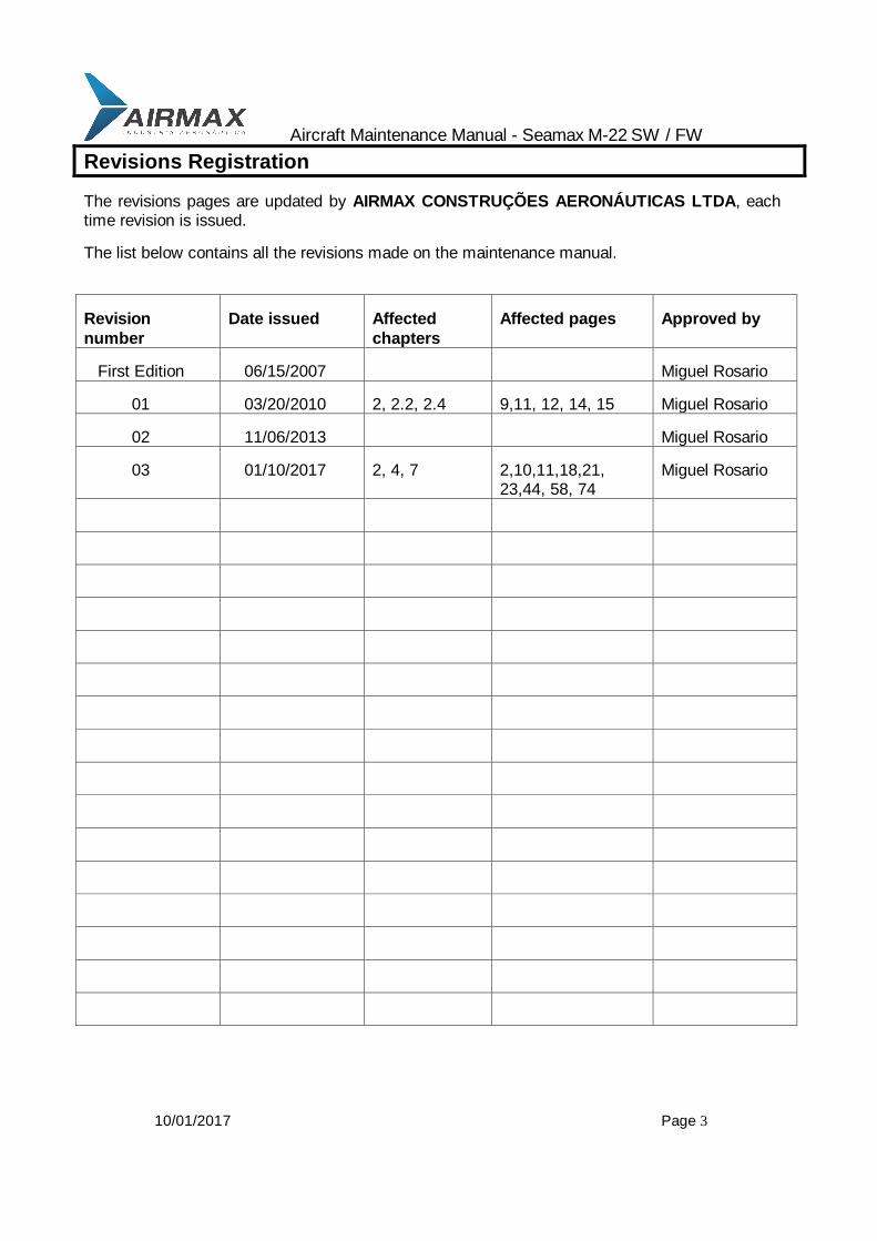
10/01/2017 Page 3
Revisions Registration
The revisions pages are updated by AIRMAX CONSTRUÇÕES AERONÁUTICAS LTDA, each time revision is issued.
The list below contains all the revisions made on the maintenance manual.
Revision
number
Date issued Affected
chapters
Affected pages Approved by
First Edition 06/15/2007 Miguel Rosario
01 03/20/2010 2, 2.2, 2.4 9,11, 12, 14, 15 Miguel Rosario
02 11/06/2013 Miguel Rosario
03 01/10/2017 2, 4, 7 2,10,11,18,21, 23,44, 58, 74
Miguel Rosario

Aircraft Maintenance Manual - Seamax M-22 SW / FW
10/01/2017 Page 4
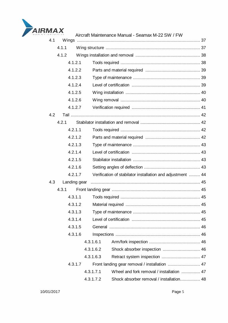
Table of Content
Seamax M-22 Aircraft Maintenance Manual front sheet ............................................................. 01
REVISIONS ............................................................................................................. 03
Table of Content .................................................................................................... 04
2 General .............................................................................................................. 11
2.1 Instructions for Reporting Possible Safety of Flight Concerns ................... 12
2.2 Views and dimensions ........................................................................... 13
2.3 List of Materials ...................................................................................... 14
2.4 List of equipments .................................................................................. 15
2.5 Sources to purchase parts ...................................................................... 16
2.6 List of disposable replacement parts ....................................................... 17
2.7 Engine specifications ............................................................................. 18
2.8 Weight and balance information ............................................................. 20
2.9 Tire inflation pressure ............................................................................. 22
2.10 Approved oils and capacities .................................................................. 23
2.11 Recommended fasteners torque values ................................................... 24
2.12 General safety information ...................................................................... 25
2.13 Instructions for reporting possible safety of flight concerns found during
inspection / maintenance ................................................................................... 26
3 Inspections ...................................................................................................... 27
3.1 Aircraft records ...................................................................................... 27
3.2 Start-up ................................................................................................. 28
3.3 Post run-up ............................................................................................ 29
3.4 Power plant ........................................................................................... 30
3.5 Wings ................................................................................................... 31
3.6 Fuselage ................................................................................................ 32
3.7 Tail ........................................................................................................ 33
3.8 Landing gear .......................................................................................... 33
3.9 Cabin .................................................................................................... 34
3.10 Inspection completion ............................................................................ 36
4 Structures ....................................................................................................... 37
Aircraft Maintenance Manual - Seamax M-22 SW / FW
10/01/2017 Page 5
4.1 Wings ................................................................................................... 37
4.1.1 Wing structure ............................................................................ 37
4.1.2 Wings installation and removal .................................................... 38
4.1.2.1 Tools required ................................................................ 38
4.1.2.2 Parts and material required ............................................ 39
4.1.2.3 Type of maintenance ...................................................... 39
4.1.2.4 Level of certification ....................................................... 39
4.1.2.5 Wing installation ............................................................ 40
4.1.2.6 Wing removal ................................................................ 40
4.1.2.7 Verification required ....................................................... 41
4.2 Tail ........................................................................................................ 42
4.2.1 Stabilator installation and removal ................................................ 42
4.2.1.1 Tools required ................................................................ 42
4.2.1.2 Parts and material required ............................................ 42
4.2.1.3 Type of maintenance ...................................................... 43
4.2.1.4 Level of certification ....................................................... 43
4.2.1.5 Stabilator installation ...................................................... 43
4.2.1.6 Setting angles of deflection ............................................. 43
4.2.1.7 Verification of stabilator installation and adjustment ......... 44
4.3 Landing gear ........................................................................................ 45
4.3.1 Front landing gear ....................................................................... 45
4.3.1.1 Tools required ................................................................ 45
4.3.1.2 Material required ............................................................ 45
4.3.1.3 Type of maintenance ...................................................... 45
4.3.1.4 Level of certification ....................................................... 45
4.3.1.5 General ......................................................................... 46
4.3.1.6 Inspections .................................................................... 46
4.3.1.6.1 Arm/fork inspection ......................................... 46
4.3.1.6.2 Shock absorber inspection .............................. 46
4.3.1.6.3 Retract system inspection ............................... 47
4.3.1.7 Front landing gear removal / installation .......................... 47
4.3.1.7.1 Wheel and fork removal / installation ............... 47
4.3.1.7.2 Shock absorber removal / installation................ 48

Aircraft Maintenance Manual - Seamax M-22 SW / FW
10/01/2017 Page 6
4.3.1.7.3 Arm removal / installation................................. 49
4.3.2 Main landing gear ....................................................................... 50
4.3.2.1 Tools required ................................................................ 50
4.3.2.2 Material required ............................................................ 50
4.3.2.3 Type of maintenance ...................................................... 50
4.3.2.4 Level of certification ....................................................... 50
4.3.2.5 General ......................................................................... 50
4.3.2.6 Inspections ......................................................................... 51
4.3.2.6.1 Arm inspection ............................................... 52
4.3.2.6.2 Shock absorber inspection .............................. 52
4.3.2.6.3 Retract system inspection ............................... 53
4.3.2.7 Main wheel and axle removal / installation ....................... 53
4.3.2.8 Triangle arm removal / installation .................................. 54
4.3.2.9 Shock absorber leg removal ........................................... 54
4.3.2.10 Retraction system tuning ................................................ 55
4.3.3 Brakes ........................................................................................ 56
4.3.3.1 Tools required ................................................................ 56
4.3.3.2 Materials required .......................................................... 56
4.3.3.3 Type of maintenance ...................................................... 56
4.3.3.4 Level of certification ....................................................... 56
4.3.3.5 General ......................................................................... 57
4.3.3.6 Inspection ...................................................................... 58
4.3.3.7 Filling system with oil ..................................................... 58
4.3.3.8 Brake pads replacement ................................................. 59
4.4 Control surfaces ..................................................................................... 61
4.4.1 Ailerons ...................................................................................... 61
4.4.1.1 Tools required ................................................................ 61
4.4.1.2 Materials required .......................................................... 61
4.4.1.3 Type of maintenance ...................................................... 61
4.4.1.4 Level of certification ....................................................... 61
4.4.1.5 General ......................................................................... 62
4.4.1.6 Inspection ...................................................................... 62
4.4.1.7 Aileron removal / installation ........................................... 62
Aircraft Maintenance Manual - Seamax M-22 SW / FW
10/01/2017 Page 7
4.4.1.8 Aileron setting ................................................................ 63
4.4.1.9 Aileron verification and adjustment ................................. 63
4.4.2 Flaps ........................................................................................ 64
4.4.2.1 Tools required ................................................................ 64
4.4.2.2 Material required ............................................................ 64
4.4.2.3 Type of maintenance ...................................................... 64
4.4.2.4 Level of certification ....................................................... 64
4.4.2.5 General ......................................................................... 64
4.4.2.6 Inspection ...................................................................... 65
4.4.2.7 Flaps removal / installation ............................................. 65
4.4.2.8 Flaps settings ................................................................ 66
4.4.2.9 Flaps verification and adjustment .................................... 66
4.4.3 Rudder ...................................................................................... 66
4.4.3.1 Tools required ................................................................ 66
4.4.3.2 Materials required .......................................................... 66
4.4.3.3 Type of maintenance ...................................................... 67
4.4.3.4 Level of certification ....................................................... 67
4.4.3.5 General ......................................................................... 67
4.4.3.6 Water rudder removal / installation ................................. 68
4.4.3.7 Rudder removal / installation .......................................... 69
4.4.3.8 Rudder adjustment ........................................................ 69
4.4.3.9 Rudder verification and adjustment ................................. 70
5 Engine .......................................................................................................... 71
6 Fuel system ..................................................................................................... 72
6.1 General ................................................................................................. 72
6.2 Tools required ........................................................................................ 72
6.3 Material required .................................................................................... 72
6.4 Type of maintenance .............................................................................. 72
6.5 Level of certification ................................................................................ 72
6.6 Fuel system inspection check list ............................................................ 73
6.7 Fuel filter ............................................................................................... 73
6.8 Fuel vents .............................................................................................. 73
Aircraft Maintenance Manual - Seamax M-22 SW / FW
10/01/2017 Page 8
6.9 Removal / installation of wing fuel tanks .................................................. 74
6.10 Header tank ........................................................................................... 75
7 Propeller
7.1 Type of maintenance ............................................................................ 76
7.2 Level of certification .............................................................................. 76
8 Instruments and avionics ............................................................................... 77
8.1 Tools required ...................................................................................... 77
8.2 Parts required ....................................................................................... 77
8.3 Type of maintenance ............................................................................ 77
8.4 Level of certification .............................................................................. 77
8.5 Maintenance ......................................................................................... 78
8.5.1 Airspeed .................................................................................... 78
8.5.2 Altimeter .................................................................................... 78
8.5.3 Vertical speed ............................................................................ 78
8.5.4 Compass ................................................................................... 79
8.5.5 Bank indicator ............................................................................ 79
8.5.6 RPM .......................................................................................... 79
8.5.7 Oil pressure ............................................................................... 79
8.5.8 Oil temperature .......................................................................... 79
8.5.9 Water temperature .................................................................... 80
8.5.10 Flap position indication lights ..................................................... 80
8.6 Pitot line and static port ........................................................................ 80
8.7 Special instruments and avionics ......................................................... 80
9 Electrical system ............................................................................................. 81
9.1 Tolls required ........................................................................................ 82
9.2 Materials required ................................................................................. 82
9.3 Type of maintenance ............................................................................ 82
9.4 Level of certification .............................................................................. 82
9.5 General ................................................................................................. 82
9.6 Inspection ............................................................................................. 82

Aircraft Maintenance Manual - Seamax M-22 SW / FW
10/01/2017 Page 9
9.7 Battery replacement .............................................................................. 83
2 9.8 Wiring diagram ..................................................................................... 84
10 Structural repairs ............................................................................................ 85
10.1 Type of maintenance ............................................................................ 85
10.2 Level of certification .............................................................................. 85
11 Painting and coating ..................................................................................... 86
11.1 Tools required ...................................................................................... 86
11.2 Materials required ................................................................................. 86
11.3 Type of maintenance ............................................................................ 86
11.4 Level of certification .............................................................................. 86
11.5 Putting .................................................................................................. 86
11.6 Priming .................................................................................................. 86
11.7 Painting ................................................................................................ 86
11.8 Polishing ............................................................................................... 87
11.9 Final verification ..................................................................................... 88
Aircraft Maintenance Manual - Seamax M-22 SW / FW
10/01/2017 Page 10
Empty Page

Aircraft Maintenance Manual - Seamax M-22 SW / FW
10/01/2017 Page 11
2. General
This is the first revision of the Seamax AMM manual, for the airplane version 2017. Minor modifications, as optional, are available to this version or earlier. Those modifications as new high performance wing tips and fins for elevator are described in this manual.
Seamax M-22 is a monohull seaplane, with a LSA-S certification, with composite fuselage / hull, elevator and wing tip floats, and an aluminum fabric covered wing, ailerons and flaps. Landing gear is a retractable tricycle configuration with differential breaking steering. One piece canopy, pusher engine and stabilator with anti servo tab are the main characteristics of this airplane.
NOTE: to accomplish the tasks described on this manual needed responsible person with following level of certification:
OWNER - responsible owner of the Light Sport Aircraft, which holds a sport pilot certificate, or higher rating.
REPAIRMAN – To make repairs on this aircraft, one must be a Light Sport Repairman Maintenance Aircraft (LSRMA) - which holds a FAA repairman certificate (LSA), with maintenance rating or equivalent (FAA A&P).
WARNING
To assure the receiving supplemental notification bulletins, and manuals revisions, is owner/operator responsibility, providing Airmax with current contact information, where they will be sent
Seamax Manufacturer is:
Airmax Construções Aeronáuticas Ltda. Aeroporto de São João da Boa Vista - SP Hangar 01 Rod. SP 344 Phone: (55) 19 99850-6810 E-mail: [email protected]
Site: www.seamaxaircraft.com
Aircraft Maintenance Manual - Seamax M-22 SW / FW
10/01/2017 Page 12
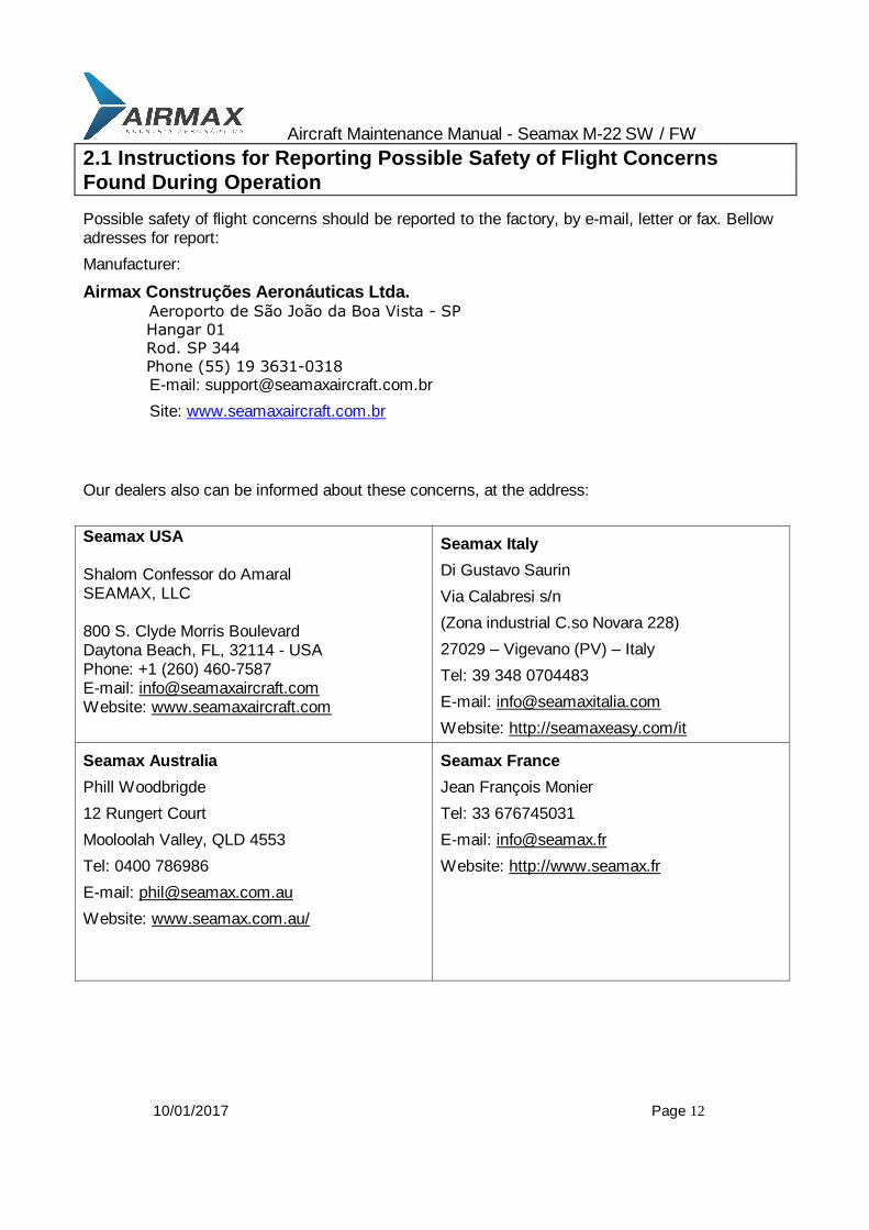
2.1 Instructions for Reporting Possible Safety of Flight Concerns
Found During Operation
Possible safety of flight concerns should be reported to the factory, by e-mail, letter or fax. Bellow adresses for report:
Manufacturer:
Airmax Construções Aeronáuticas Ltda. Aeroporto de São João da Boa Vista - SP Hangar 01 Rod. SP 344 Phone (55) 19 3631-0318 E-mail: [email protected]
Site: www.seamaxaircraft.com.br
Our dealers also can be informed about these concerns, at the address:
Seamax USA Shalom Confessor do Amaral SEAMAX, LLC 800 S. Clyde Morris Boulevard Daytona Beach, FL, 32114 - USA Phone: +1 (260) 460-7587 E-mail: [email protected] Website: www.seamaxaircraft.com
Seamax Italy
Di Gustavo Saurin
Via Calabresi s/n
(Zona industrial C.so Novara 228)
27029 – Vigevano (PV) – Italy
Tel: 39 348 0704483
E-mail: [email protected]
Website: http://seamaxeasy.com/it
Seamax Australia
Phill Woodbrigde
12 Rungert Court
Mooloolah Valley, QLD 4553
Tel: 0400 786986
E-mail: [email protected]
Website: www.seamax.com.au/
Seamax France
Jean François Monier
Tel: 33 676745031
E-mail: [email protected]
Website: http://www.seamax.fr

Aircraft Maintenance Manual - Seamax M-22 SW / FW
10/01/2017 Page 13
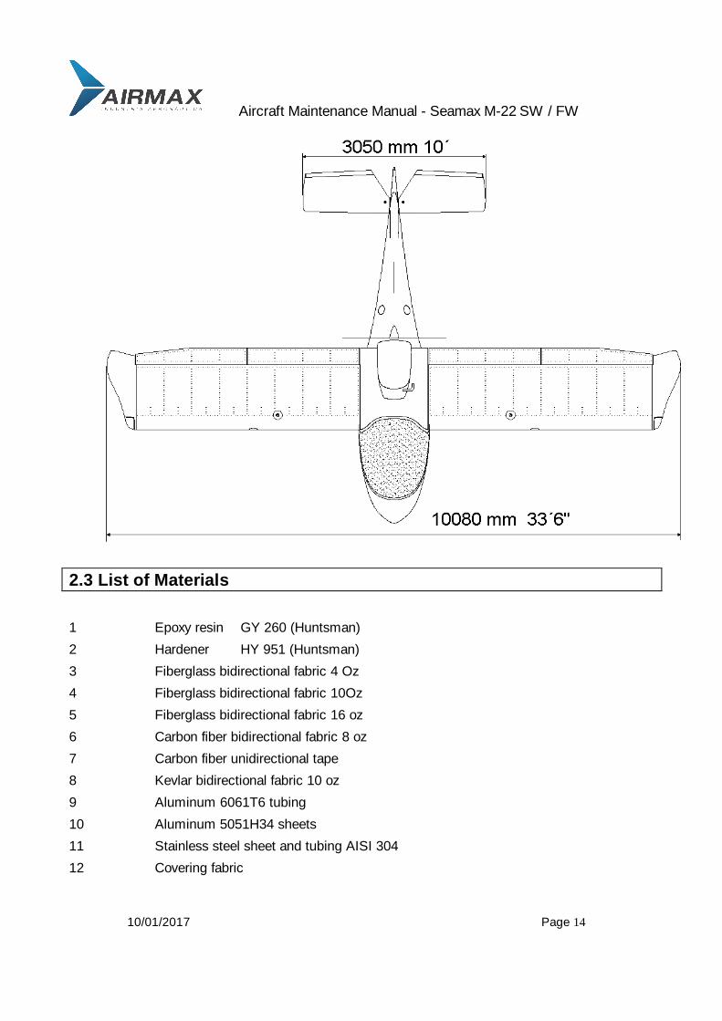
2.2 Views and Dimensions
Wing span 33, 07 ft 10, 08 m
Stabilator span 10, 09 ft 3, 07 m
Vertical fin 6, 4 ft 1905 m
Length 19, 8 ft 6,05 m
Wing area 129, 6 sqft 12, 04 sqm
Height 6, 2 ft 1, 9 m
Aircraft Maintenance Manual - Seamax M-22 SW / FW
10/01/2017 Page 14
2.3 List of Materials
1 Epoxy resin GY 260 (Huntsman)
2 Hardener HY 951 (Huntsman)
3 Fiberglass bidirectional fabric 4 Oz
4 Fiberglass bidirectional fabric 10Oz
5 Fiberglass bidirectional fabric 16 oz
6 Carbon fiber bidirectional fabric 8 oz
7 Carbon fiber unidirectional tape
8 Kevlar bidirectional fabric 10 oz
9 Aluminum 6061T6 tubing
10 Aluminum 5051H34 sheets
11 Stainless steel sheet and tubing AISI 304
12 Covering fabric

Aircraft Maintenance Manual - Seamax M-22 SW / FW
10/01/2017 Page 15
2.4 List of Equipments
Seamax M-22 S-LSA “ready to fly” seaplane
Standard Equipment
Outside paint, UV resistant, PU base white;
Outside decorative stripes in vinyl;
One piece canopy, tinted green with two snap vents;
Inside leather finishing;
Three point seat belts;
Adjustable seats, in leather cushions;
Carpets for both sides;
Front pockets in leather;
Central joystick mount;
Dual power levels;
Dual hydraulic brakes, differential for steering;
Electric pitch trim with level on dashboard;
Electric actuated flaps, with position lights on dashboard;
Two fuel valves, one for each tank;
Two wing tanks and a central heater tank;
Retractable, electric activated tricycle landing gear with position lights on dashboard;
Ignition switch with key;
Circuit brakes for all electric system;
Retractable water rudder;
Landing lights;
Strobe lights;
Navigation lights;
Electric fuel pump;
Electric bilge pump.
Engine
Rotax 912 ULS 100hp, equipped with clutch and stainless steel exhaust system.

Aircraft Maintenance Manual - Seamax M-22 SW / FW
10/01/2017 Page 16
Standard Flight Instruments
3 1/8 UMA altimeter
UMA Vertical speed indicator
UMA airspeed indicator
Magnetic compass
Optional Flight Instruments
Glass instruments Dynon D-100, or D-180
Engine Instruments
Mitchell 2 ¼ analogical instruments
Fuel pressure
Voltmeter
Oil pressure
Oil temperature
Cylinder head temperature
UMA 2 ¼ RPM
Propeller
Warp drive, three blades constant speed shape, with nickel protection leading edge, HPL-R hub
Fiberglass spinner is optional.
Communication & Navigation (optional)
VHF Radio X-com
Transponder Becker with “C” mode
ELT Ameri-king corporation model AK-450 per TSO-C91a and DO-160c Requirements.
Options
VHF radio, Xponder, GPS, EFIS, EMS, Auto pilot, Intercom, PCAS, GPS.
Aircraft Maintenance Manual - Seamax M-22 SW / FW
10/01/2017 Page 17
General Options
Canopy protection cover;
Jack for landing gear test;
Hardware for water operation;
Fins for elevator;
Wing tips model 2010.
2.5 Sources to Purchase Parts
All the spare parts can be purchased from the factory, AIRMAX CONSTRUÇÕES
AERONÁUTICAS LTDA. (www.seamaxaircraft.com.br) or from the official dealer, in France (www.seamax.fr), in Australia (www.seamax.com.au) and in Italy (www.seamaxeasy.com/it). Usual aircraft parts as bolts, nuts, rivets, turnbuckles, etc, can be purchase on any aviation supply company.
All parts can be checked and ordered, using the information’s and drawings along this maintenance manual.
2.6 List of Disposable Replacement Parts
Air filter KN
Fuel filter fuel filter
Oil filter oil filter
Main wheel tire 500X5
Main wheel tube 500X5 bent valve
Front wheel tire 350X4
Front wheel tube 350X4 bent valve
Brake pads brake pads
Engine Spark plugs spark plugs

Aircraft Maintenance Manual - Seamax M-22 SW / FW
10/01/2017 Page 18
2.7 Engine Specifications
NOTE: for complete information about engine specifications and limitation, read the
Maintenance Manual for Rotax 912 series, supplied with the aircraft
Manufacturer Rotax
Type 912
Model ULS/S
General Specifications:
4 stroke, 4 cylinders opposed, one central camshaft, push rods OHV
Liquid cooled heads
Ram air cooled cylinders
Dry sump forced lubrication
2 constant depression carburetors
Mechanical fuel pump
Propeller drive via reduction gear with shock absorber and clutch, ratio 2,43:1
Electric starter
Integrated AC generator with external rectifier/regulator
Operating Limits
Speed
Take off speed 5800 rpm/min (5 minutes)
Max. Continuous speed 5500 rpm/min
Idle speed 1400 rpm/min
Performance
Take off performance 73,5 KW @ 5800 rpm
Max. Continuous performance 69 KW @ 5500 rpm
Acceleration
Max. 5 seconds at max -0,5 g´s
Oil pressure
Max. 7 bar (short period, cold start)
Min. 0,8 bar (12 psi) below 3500 rpm
Normal 2,0-5,0 bar (29-7 psi) above 3500 rpm

Aircraft Maintenance Manual - Seamax M-22 SW / FW
10/01/2017 Page 19
Oil temperature
Max 130 C (266 F)
Min 50 C - 130 (120 F – 266 F)
Normal 90-110 C (190-230 F)
Cylinder head temperature
Normal 130 (266)
Attention 130 (266)–135 (275)
Max 135 C (275 F)
Engine start, operating temperature
Max 50 C (120 F)
Min -25 C (-13 F)
Fuel pressure
Max 0, 4 bar (5, 8 psi)
Min 0, 15 bar (2, 2 psi)
More detailed engine information is available in the Maintenance Manual for Rotax, type
912, supplied with the aircraft
Aircraft Maintenance Manual - Seamax M-22 SW / FW
10/01/2017 Page 20
2.8 Weight and Balance Information
Weights:
Minimum load with ballast on front seats, 122 lb 55 kg
Maximum load on front seats, w/o ballast 489 lb 220 kg
Maximum take off weight 1320 lb 600 kg
Baggage weight (limited by MTOW) 44 lb 20 kg
Empty weight (standard) 715 lb 325 kg
Datum line is wing leading edge
Level line is wing lower surface, at root section, with 4,6 degrees positive.
Baggage is located very close to CG position, so limit of baggage weight is only limited by maximum take off weight.
Leveling: The airplane should be leveled by the bottom of the wing with + 4, 6 degrees positive.
Main landing gear wheels should be positioned over level blocks. Depending on shock absorbers on main landing gear, those blocks probably will have different heights in different airplanes.
Measuring: Measurement should be taken with a bob weight, marked on ground and then measured.
Weighting: Using one or three scales, the airplane should stay on same level for weighting.
Aircraft Maintenance Manual - Seamax M-22 SW / FW
10/01/2017 Page 21
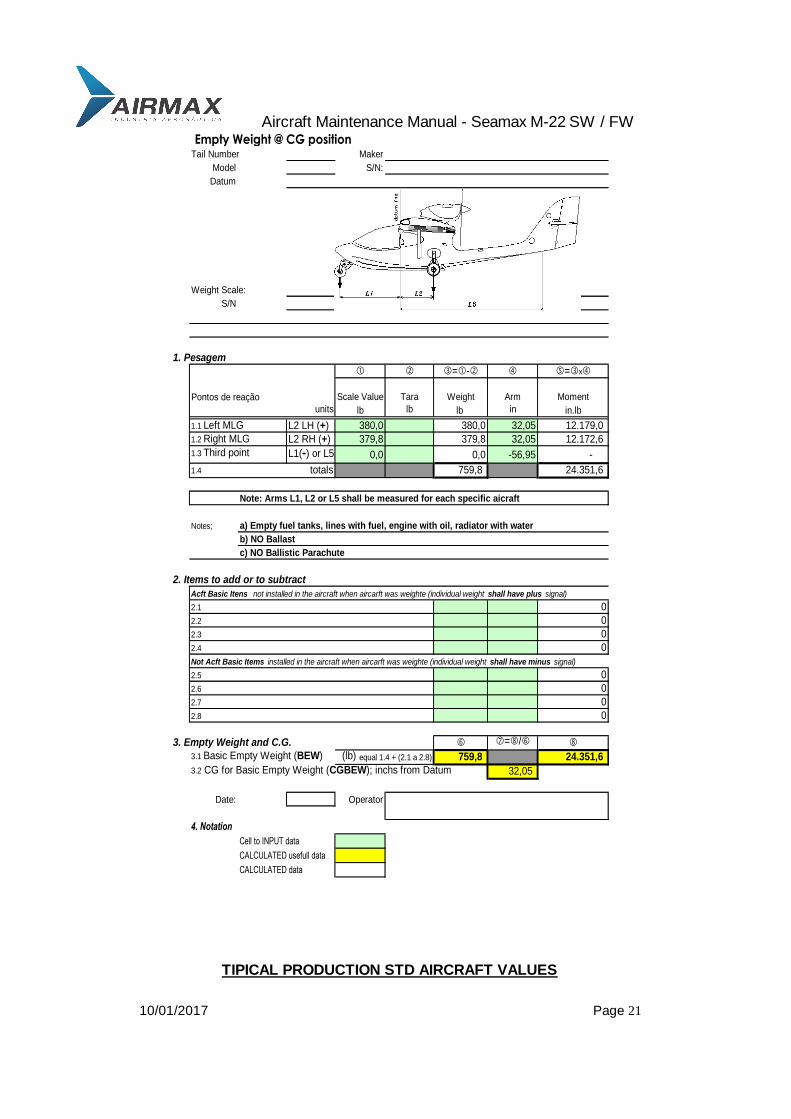
Empty Weight @ CG positionTail Number Maker
Model S/N:
Datum
Weight Scale: Model:
S/N Date last certfication:
1. Pesagem
=- =x
Pontos de reação Scale Value Tara Weight Arm Moment
units lb lb lb in in.lb
1.1 Left MLG L2 LH (+) 380,0 380,0 32,05 12.179,0
1.2 Right MLG L2 RH (+) 379,8 379,8 32,05 12.172,6
1.3 Third point L1(-) or L5(+) 0,0 0,0 -56,95 -
1.4 totals 759,8 24.351,6
Note: Arms L1, L2 or L5 shall be measured for each specific aicraft
Notes; a) Empty fuel tanks, lines with fuel, engine with oil, radiator with water
b) NO Ballast
c) NO Ballistic Parachute
2. Items to add or to subtract
2.1 0
2.2 0
2.3 0
2.4 0
2.5 0
2.6 0
2.7 0
2.8 0
3. Empty Weight and C.G. =/
3.1 Basic Empty Weight (BEW) (lb) equal 1.4 + (2.1 a 2.8) 759,8 24.351,6
3.2 CG for Basic Empty Weight (CGBEW); inchs from Datum 32,05
Date: Operator
4. Notation
Cell to INPUT data
CALCULATED usefull data
CALCULATED data
Acft Basic Itens not installed in the aircraft when aircarft was weighte (individual weight shall have plus signal)
Not Acft Basic Items installed in the aircraft when aircarft was weighte (individual weight shall have minus signal)
TIPICAL PRODUCTION STD AIRCRAFT VALUES

Aircraft Maintenance Manual - Seamax M-22 SW / FW
10/01/2017 Page 22
4.1 Fuel for Taxi, Climb and Cruise 5 gallons 29
4.2 Reserve Fuel (alternate) 0 gallons 0
4.3 Fuel for descent and hold gallons 0
4.44.4 Total Fuel (4.1+4.2+4.3) 5 gallons 29 55,00 1.614
4. Ramp Weight (equal to 3. + 4.4) 1.099 25.986
5.1 Fuel for taxi gal - 55,00 0
5. Take-off Weight item 4 + 5.1 1.099 25.986
CG Take-off (inch to DATUM) 23,64
6.1 Estimate fuel comsumption to destiny 5 29
6.2 Fuel at Landing (4.4 - 6.1) 0 0 55,00 0
6. Landing Weight (3. + 6.2) 1.070 24.372
CG Landing (inch to DATUM) 22,78
date operator
7. Design Limits
7.1 Maximum Take Off Weight 1320 lb
7.2 C.G limits front 17,70 rear 27,60 in
7.3 Solo Flight Requires 23 lb of ballast 23 at 46,85 ahead of datum
7.4 Maximum Fuel capacity 24,3 gallons
7.5 Maximum Bagagge capacity 10,0 lbs
7.6 Most aft weight & CGSeats (190 lb), Fuel (17 gal) 1085 lb 24,44 in
7.7 Most aft weight & CGSeats (180 lb), Fuel (18 gal) 1069 lb 27,44 in
7.8 Most aft weight & CGSeats (140 lb), Fuel (11 gal) 998 lb 27,60 in
7.9 Most Forward Weight & CGSeats (300 lb), Fuel (5 gal) 1099 lb 23,64 in
7.10 Most Forward Weight & CGSeats (300 lb), Fuel (0 gal) 1070 lb 22,78 in
7.11 Flight Test Weight lb in
8. Notation
Cell to INPUT data
CALCULATED usefull data
CALCULATED data
Factory average values XX

Aircraft Maintenance Manual - Seamax M-22 SW / FW
10/01/2017 Page 23
2.9 Tire Inflation Pressure
Front tire, 350X4 25 - 30 psi 1,8 – 2,1 bar
Main tires, 500X5 15 - 22 psi 1,0 – 1,5 bar
2.10 Approved Oils and Capacities
Fuel:
Wing tanks (each) 12, 5 us gal 46 l
Total wings 25,0 us gal 92 l
Heather tank 1, 6 us gal 6 l
Total fuel 26, 0 us gal 98 l
Usable fuel 24, 8 us gal 94 l
Fuel specification: Minimum RON 95; Minimum AKI 92 octane auto fuel
Usable types: EN 228 Premium; EN 228 Premium Plus, AVGAS 100LL
Oil:
NOTE: See Rotax Operator’s Manual, supplied with the aircraft, for correct oil information.
Use motorcycle oil of a registered brand, with gear additives.
Use only API classification “SF” or “SG”
Oil Capacity: 3 L (6.4 liq pt) minimum 2 L (4.2 liq pt) Oil Consumption: maximum 0.1 L/H (0.2 liq pt/h) Oil viscosity: See chapter 10 of Rotax operator’s manual For complete oil specification see the Rotax operator’s manual.
Cooling Fluid:
NOTE: See Rotax Operator’s Manual, supplied with the aircraft, for correct cooling liquid information.
Cooling liquid capacity 5, 3 liq pt 2,5 l
NOTE: Do not mix waterless cooling fluid with normal ethylene glycol fluids. Cooling systems must be washed before changing fluid type.

Aircraft Maintenance Manual - Seamax M-22 SW / FW
10/01/2017 Page 24
Braking Fluid:
Use automatic transmission oil type (ex. Mobil ATF ),
NOTE: do not use automotive brake fluid oil, usually used on brake systems.
Oil capacity 1.1 liq pt 0,5 l
2.11 Recommended Fasteners Torque Values
All torque values are in inch-pound
#10-32 #10-24 1/4- 28 1/4-20 5/16-24 5/16-18
Bolt 20-25 12-15 50-70 40-50 100-140 80-90
Nut 12-15 12-15 30-40 25-30 60-85 48-55
Over composite parts
6-7 6-7 15-20 12-15 30-42 24-27
NOTE: Engine torques are available on Rotax Operator’s Manual, supplied with the aircraft.
2.12 General Safety Information
Always remove the ignition key, when not inside the aircraft. Ignition key is located on rear part of the overhead panel. Use central console pocket to keep keys, on ground.
Check the landing gear switch position, before turn on the master switch.
Before leaving the airplane, check if all switches are off, specially the master switch.
Check oil level, water level and general engine conditions at least once a day, before the first flight, by removing the upper part of engine cowling, opening 11 “D-zuz” bolts.
Aircraft Maintenance Manual - Seamax M-22 SW / FW
10/01/2017 Page 25
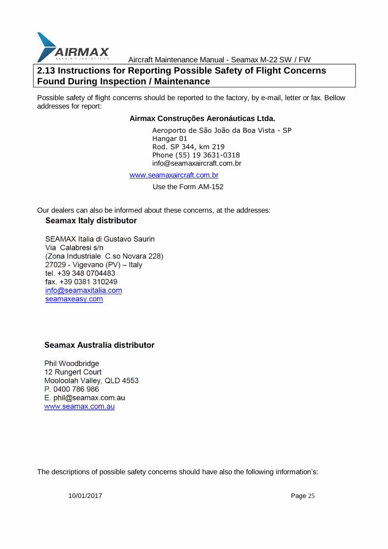
2.13 Instructions for Reporting Possible Safety of Flight Concerns
Found During Inspection / Maintenance
Possible safety of flight concerns should be reported to the factory, by e-mail, letter or fax. Bellow addresses for report:
Airmax Construções Aeronáuticas Ltda.
Aeroporto de São João da Boa Vista - SP Hangar 01 Rod. SP 344, km 219 Phone (55) 19 3631-0318 [email protected]
www.seamaxaircraft.com.br
Use the Form AM-152
Our dealers can also be informed about these concerns, at the addresses:
The descriptions of possible safety concerns should have also the following information’s:
Aircraft Maintenance Manual - Seamax M-22 SW / FW
10/01/2017 Page 26
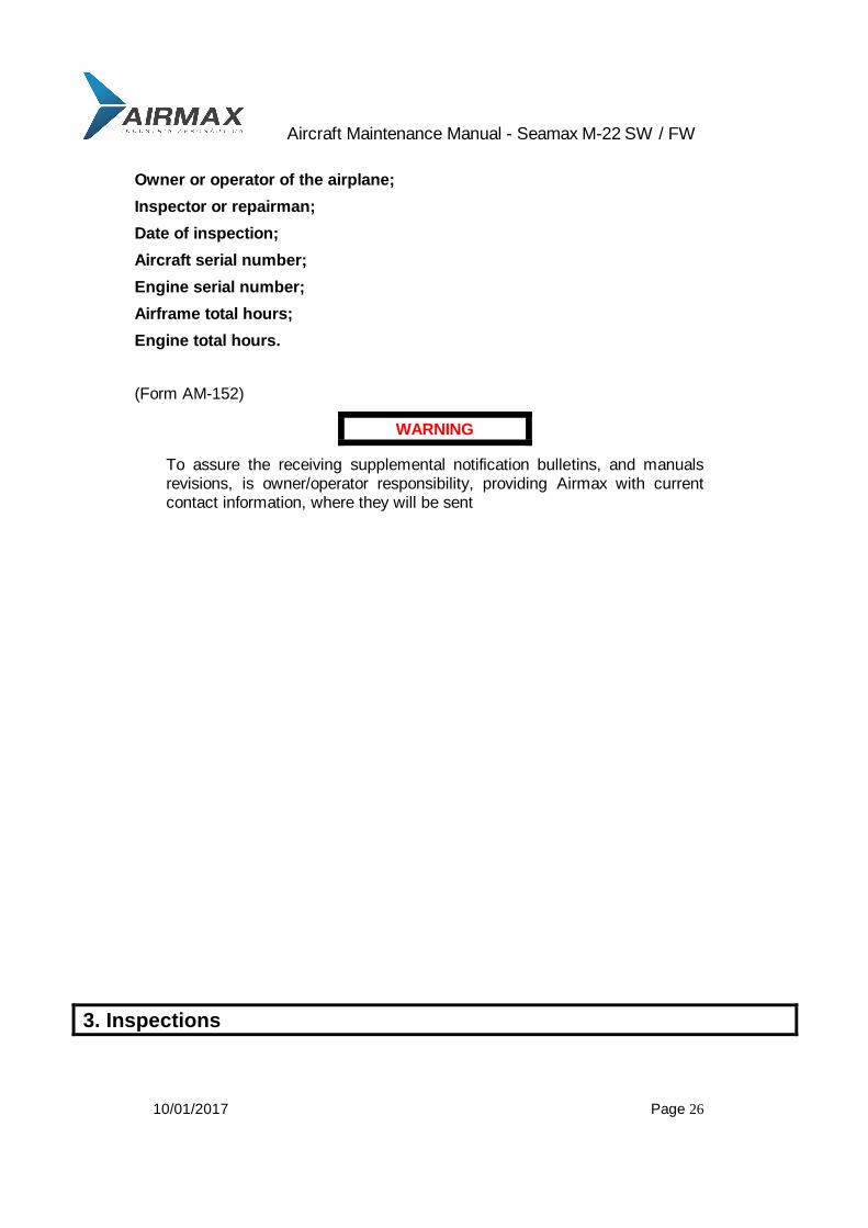
Owner or operator of the airplane;
Inspector or repairman;
Date of inspection;
Aircraft serial number;
Engine serial number;
Airframe total hours;
Engine total hours.
(Form AM-152)
WARNING
To assure the receiving supplemental notification bulletins, and manuals revisions, is owner/operator responsibility, providing Airmax with current contact information, where they will be sent
3. Inspections
Aircraft Maintenance Manual - Seamax M-22 SW / FW
10/01/2017 Page 27
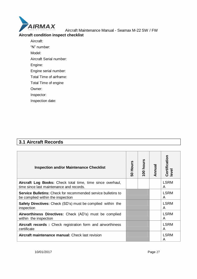
Aircraft condition inspect checklist
Aircraft:
“N” number:
Model:
Aircraft Serial number:
Engine:
Engine serial number:
Total Time of airframe:
Total Time of engine
Owner:
Inspector:
Inspection date:
3.1 Aircraft Records
Inspection and/or Maintenance Checklist
50 H
ou
rs
100 h
ou
rs
An
nu
al
Cert
ific
ati
on
level
Aircraft Log Books: Check total time, time since overhaul, time since last maintenance and records.
LSRMA
Service Bulletins: Check for recommended service bulletins to be complied within the inspection
LSRMA
Safety Directives: Check (SD’s) must be complied within the inspection
LSRMA
Airworthiness Directives: Check (AD’s) must be complied within the inspection
LSRMA
Aircraft records : Check registration form and airworthiness certificate
LSRMA
Aircraft maintenance manual: Check last revision LSRMA

Aircraft Maintenance Manual - Seamax M-22 SW / FW
10/01/2017 Page 28
Pilot’s Operating Handbook (POH): Check last revisions, check equipment list and Weight and balance forms.
LSRMA
3.2 Start-up
Inspection and/or Maintenance Check-list
50 Hours
100Hours
Annual
Before star-up
Pre-Inspection Post -Inspection
Battery
ELT battery test
Fuel valves
Start-up
Starter
Oil pressure
Instruments
Avionics
Ignition test
brakes
Before shut down
Oil pressure
Idle RPM
Oil temperature
Battery
Before leaving airplane
Switches off
Check fuel odors
Fuel valves off
NOTES:
Aircraft Maintenance Manual - Seamax M-22 SW / FW
10/01/2017 Page 29
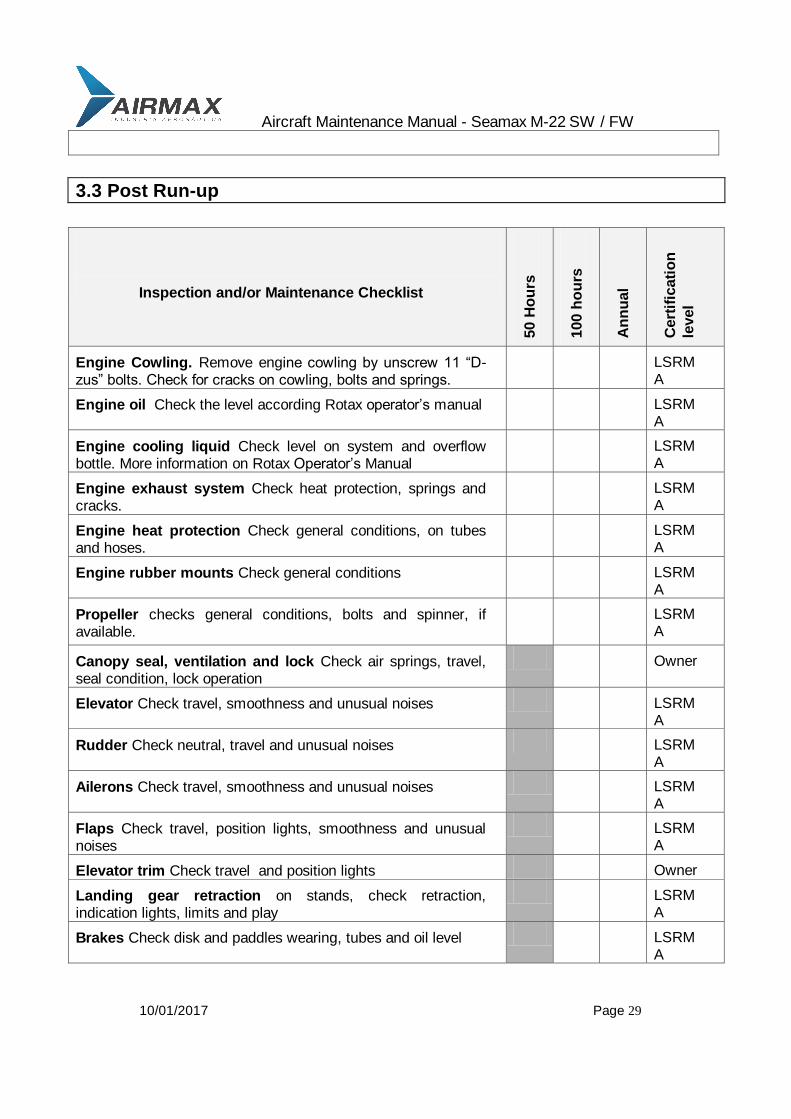
3.3 Post Run-up
Inspection and/or Maintenance Checklist
50 H
ou
rs
100 h
ou
rs
An
nu
al
Cert
ific
ati
on
level
Engine Cowling. Remove engine cowling by unscrew 11 “D-zus” bolts. Check for cracks on cowling, bolts and springs.
LSRMA
Engine oil Check the level according Rotax operator’s manual LSRMA
Engine cooling liquid Check level on system and overflow bottle. More information on Rotax Operator’s Manual
LSRMA
Engine exhaust system Check heat protection, springs and cracks.
LSRMA
Engine heat protection Check general conditions, on tubes and hoses.
LSRMA
Engine rubber mounts Check general conditions LSRMA
Propeller checks general conditions, bolts and spinner, if available.
LSRMA
Canopy seal, ventilation and lock Check air springs, travel, seal condition, lock operation
Owner
Elevator Check travel, smoothness and unusual noises LSRMA
Rudder Check neutral, travel and unusual noises LSRMA
Ailerons Check travel, smoothness and unusual noises LSRMA
Flaps Check travel, position lights, smoothness and unusual noises
LSRMA
Elevator trim Check travel and position lights Owner
Landing gear retraction on stands, check retraction, indication lights, limits and play
LSRMA
Brakes Check disk and paddles wearing, tubes and oil level LSRMA

Aircraft Maintenance Manual - Seamax M-22 SW / FW
10/01/2017 Page 30
Inspection window remove vinyl seals, remove inspection windows, clean it, and check all inside links and connections.
LSRMA
Inside fairings, remove all inside fairings to check all systems and equipments behind, also seats and carpets
LSRMA
Battery Check fixation, cables and general condition LSRMA
3.4 Power Plant
Inspection and/or Maintenance Checklist
50 H
ou
rs
100 h
ou
rs
An
nu
al
Cert
ific
ati
on
level
Engine check general conditions clean and Inspect it as required on Rotax Maintenance Manual.
Owner
Carburetors check carburetors fixation, leaks, throttle and choke cables and travel.
Owner
Air filters check fixation, general conditions and cleanliness Owner
Fuel lines check for general conditions, heat protection, proper fixation, leaks, bents, etc.
LSRMA
Propeller check for cracks, erosion, and corrosion on hub, re-torque fixation bolts if necessary. Check hub fixation and condition, if available.
LSRMA
Exhaust system check for broken springs, heat protection, cracks and gas leaking points
Owner
Water radiator checks fixation points and rubber conditions, hoses, heat protection and clamps.
LSRMA
Oil radiator check fixation points, hoses, heat protection and clamps.
LSRMA
Engine mounts check for corrosion points and cracks. LSRMA
Engine rubber mounts check general conditions of rubber Owner
Sensors and electric cables check general conditions, heat protection and fixation
Owner
General fire sleeve conditions check general conditions and fixation points
Owner
Vent lines check heat protection, fixation and general conditions
LSRMA
Aircraft Maintenance Manual - Seamax M-22 SW / FW
10/01/2017 Page 31
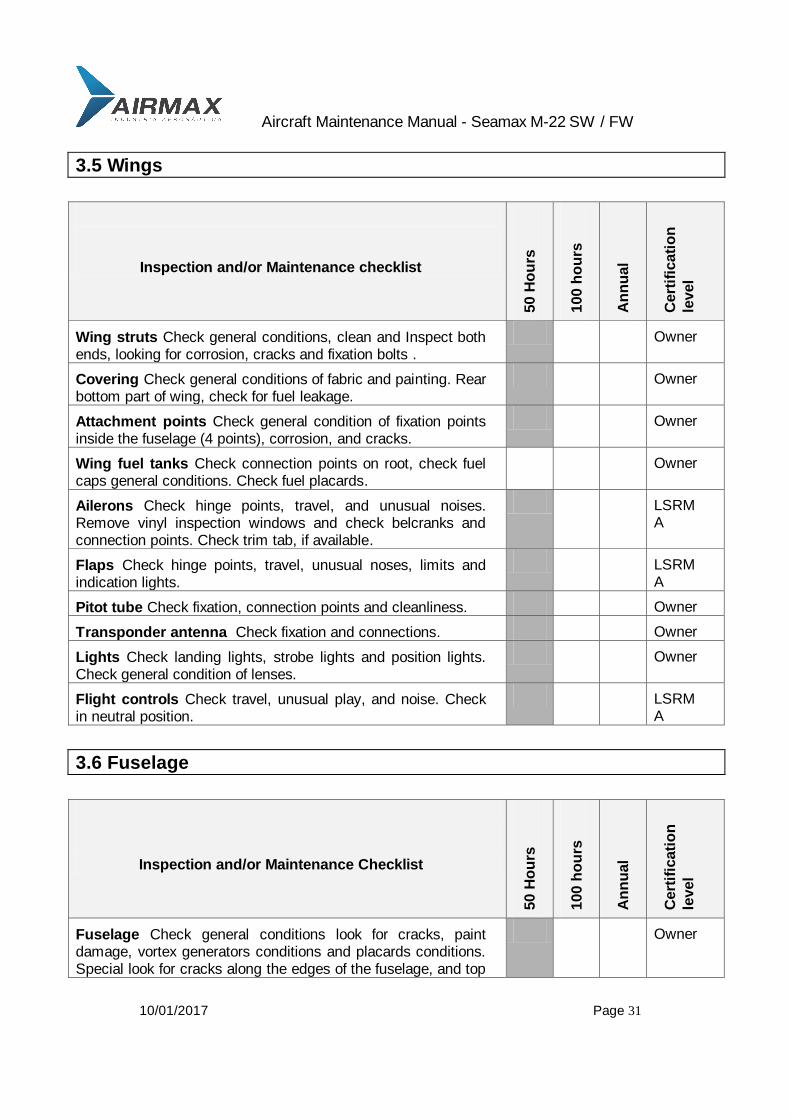
3.5 Wings
Inspection and/or Maintenance checklist
50 H
ou
rs
100 h
ou
rs
An
nu
al
Cert
ific
ati
on
level
Wing struts Check general conditions, clean and Inspect both ends, looking for corrosion, cracks and fixation bolts .
Owner
Covering Check general conditions of fabric and painting. Rear bottom part of wing, check for fuel leakage.
Owner
Attachment points Check general condition of fixation points inside the fuselage (4 points), corrosion, and cracks.
Owner
Wing fuel tanks Check connection points on root, check fuel caps general conditions. Check fuel placards.
Owner
Ailerons Check hinge points, travel, and unusual noises. Remove vinyl inspection windows and check belcranks and connection points. Check trim tab, if available.
LSRMA
Flaps Check hinge points, travel, unusual noses, limits and indication lights.
LSRMA
Pitot tube Check fixation, connection points and cleanliness. Owner
Transponder antenna Check fixation and connections. Owner
Lights Check landing lights, strobe lights and position lights. Check general condition of lenses.
Owner
Flight controls Check travel, unusual play, and noise. Check in neutral position.
LSRMA
3.6 Fuselage
Inspection and/or Maintenance Checklist
50 H
ou
rs
100 h
ou
rs
An
nu
al
Cert
ific
ati
on
level
Fuselage Check general conditions look for cracks, paint damage, vortex generators conditions and placards conditions. Special look for cracks along the edges of the fuselage, and top
Owner
Aircraft Maintenance Manual - Seamax M-22 SW / FW
10/01/2017 Page 32
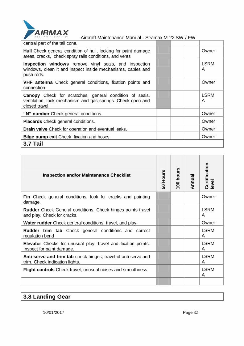
central part of the tail cone.
Hull Check general condition of hull, looking for paint damage areas, cracks, check spray rails conditions, and vents
Owner
Inspection windows remove vinyl seals, and inspection windows, clean it and inspect inside mechanisms, cables and push rods.
LSRMA
VHF antenna Check general conditions, fixation points and connection
Owner
Canopy Check for scratches, general condition of seals, ventilation, lock mechanism and gas springs. Check open and closed travel.
LSRMA
“N” number Check general conditions. Owner
Placards Check general conditions. Owner
Drain valve Check for operation and eventual leaks. Owner
Bilge pump exit Check fixation and hoses. Owner
3.7 Tail
Inspection and/or Maintenance Checklist
50 H
ou
rs
100 h
ou
rs
An
nu
al
Cert
ific
ati
on
level
Fin Check general conditions, look for cracks and painting damage.
Owner
Rudder Check General conditions. Check hinges points travel and play. Check for cracks.
LSRMA
Water rudder Check general conditions, travel, and play. Owner
Rudder trim tab Check general conditions and correct regulation bend
LSRMA
Elevator Checks for unusual play, travel and fixation points. Inspect for paint damage.
LSRMA
Anti servo and trim tab check hinges, travel of anti servo and trim. Check indication lights.
LSRMA
Flight controls Check travel, unusual noises and smoothness LSRMA
3.8 Landing Gear
Aircraft Maintenance Manual - Seamax M-22 SW / FW
10/01/2017 Page 33
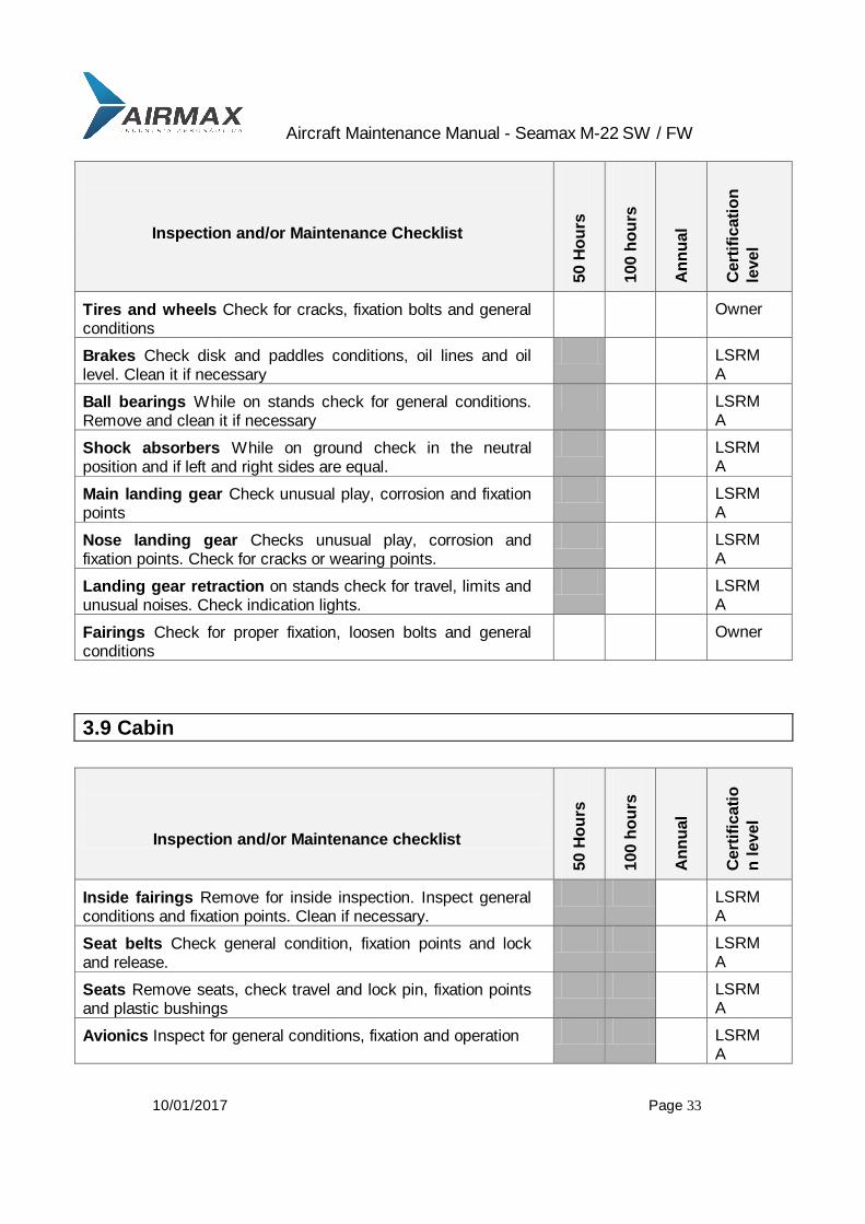
Inspection and/or Maintenance Checklist
50 H
ou
rs
100 h
ou
rs
An
nu
al
Cert
ific
ati
on
level
Tires and wheels Check for cracks, fixation bolts and general conditions
Owner
Brakes Check disk and paddles conditions, oil lines and oil level. Clean it if necessary
LSRMA
Ball bearings While on stands check for general conditions. Remove and clean it if necessary
LSRMA
Shock absorbers While on ground check in the neutral position and if left and right sides are equal.
LSRMA
Main landing gear Check unusual play, corrosion and fixation points
LSRMA
Nose landing gear Checks unusual play, corrosion and fixation points. Check for cracks or wearing points.
LSRMA
Landing gear retraction on stands check for travel, limits and unusual noises. Check indication lights.
LSRMA
Fairings Check for proper fixation, loosen bolts and general conditions
Owner
3.9 Cabin
Inspection and/or Maintenance checklist
50 H
ou
rs
100 h
ou
rs
An
nu
al
Cert
ific
ati
o
n l
evel
Inside fairings Remove for inside inspection. Inspect general conditions and fixation points. Clean if necessary.
LSRMA
Seat belts Check general condition, fixation points and lock and release.
LSRMA
Seats Remove seats, check travel and lock pin, fixation points and plastic bushings
LSRMA
Avionics Inspect for general conditions, fixation and operation LSRMA
Aircraft Maintenance Manual - Seamax M-22 SW / FW
10/01/2017 Page 34
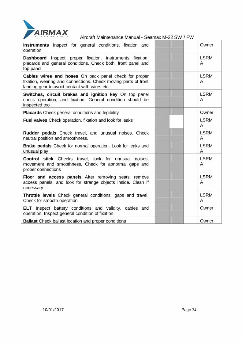
Instruments Inspect for general conditions, fixation and operation
Owner
Dashboard Inspect proper fixation, instruments fixation, placards and general conditions. Check both, front panel and top panel
LSRMA
Cables wires and hoses On back panel check for proper fixation, wearing and connections. Check moving parts of front landing gear to avoid contact with wires etc.
LSRMA
Switches, circuit brakes and ignition key On top panel check operation, and fixation. General condition should be inspected too.
LSRMA
Placards Check general conditions and legibility Owner
Fuel valves Check operation, fixation and look for leaks LSRMA
Rudder pedals Check travel, and unusual noises. Check neutral position and smoothness.
LSRMA
Brake pedals Check for normal operation. Look for leaks and unusual play
LSRMA
Control stick Checks travel, look for unusual noises, movement and smoothness. Check for abnormal gaps and proper connections
LSRMA
Floor and access panels After removing seats, remove access panels, and look for strange objects inside. Clean if necessary
LSRMA
Throttle levels Check general conditions, gaps and travel. Check for smooth operation.
LSRMA
ELT Inspect battery conditions and validity, cables and operation. Inspect general condition of fixation
Owner
Ballast Check ballast location and proper conditions Owner

Aircraft Maintenance Manual - Seamax M-22 SW / FW
10/01/2017 Page 35
3.10 Inspection Completion
Inspection and/or Maintenance Checklist
50 H
ou
rs
100 h
ou
rs
An
nu
al
Cert
ific
ati
on
level
Wings Check for foreign objects and tools, replace vinyl inspection windows
Owner
Fuselage Check for tools and foreign objects, glue inspection windows and apply vinyl seals
Owner
Engine Check fluid levels and general conditions before start it up. Check on Rotax Operator’s Manual for extra information.
Owner
Start up With out the engine cowling, start up, and let it warm. After shut off look for leaks and unusual conditions, before close the cowling
Owner
Cabin Reinstalls all fairings, seats belts and carpets. Look for tools or parts inside.
Owner
Aircraft Records Record all required entries on logbooks, and check for AD, SD and SB compliance
Owner
Aircraft Maintenance Manual - Seamax M-22 SW / FW
10/01/2017 Page 36
4 Structures
4.1 Wings
4.1.1 Wing Structure
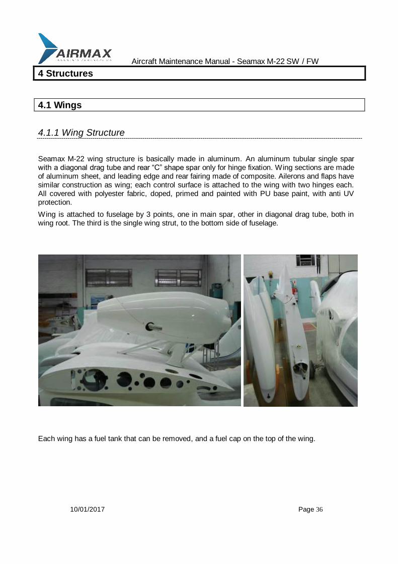
Seamax M-22 wing structure is basically made in aluminum. An aluminum tubular single spar with a diagonal drag tube and rear “C” shape spar only for hinge fixation. Wing sections are made of aluminum sheet, and leading edge and rear fairing made of composite. Ailerons and flaps have similar construction as wing; each control surface is attached to the wing with two hinges each. All covered with polyester fabric, doped, primed and painted with PU base paint, with anti UV protection.
Wing is attached to fuselage by 3 points, one in main spar, other in diagonal drag tube, both in wing root. The third is the single wing strut, to the bottom side of fuselage.
Each wing has a fuel tank that can be removed, and a fuel cap on the top of the wing.
Aircraft Maintenance Manual - Seamax M-22 SW / FW
10/01/2017 Page 37
4.1.2 Wings Installation and Removal
To install and remove the wings, be careful to disconnect or reconnect all the wires, cables and hoses, as described bellow. Be sure the fuel wing fuel tanks are empty, to avoid leaks during the installation or removal process.
4.1.2.1 Tools required
Wrench 7/16 02 required
Wrench ½ 02 required
Phillips screw dive ¼ 01 required help holes alignment
Allen wrench 5/32 01 required
4.1.2.2 Parts and material required
Multipurpose grease
Lock wire
4.1.2.3 Type of maintenance
Line
4.1.2.4 Level of certification
Light Sport Aircraft Repairman Maintenance Airplane (LSRMA)
4.1.2.5 Wing installation
The procedures, sequences and general instruction described for this operation, are only applicable for a normal wing installations or removal. For damage parts or repaired parts please contact Airmax or dealers. Three people are needed for this operation.
1- Prepare both wings, wing struts, bolts, nuts and fairings needed to this operation; apply some grease on the wing fitting points and on the same points in the fuselage. Bolts can be greased too.
Aircraft Maintenance Manual - Seamax M-22 SW / FW
10/01/2017 Page 38
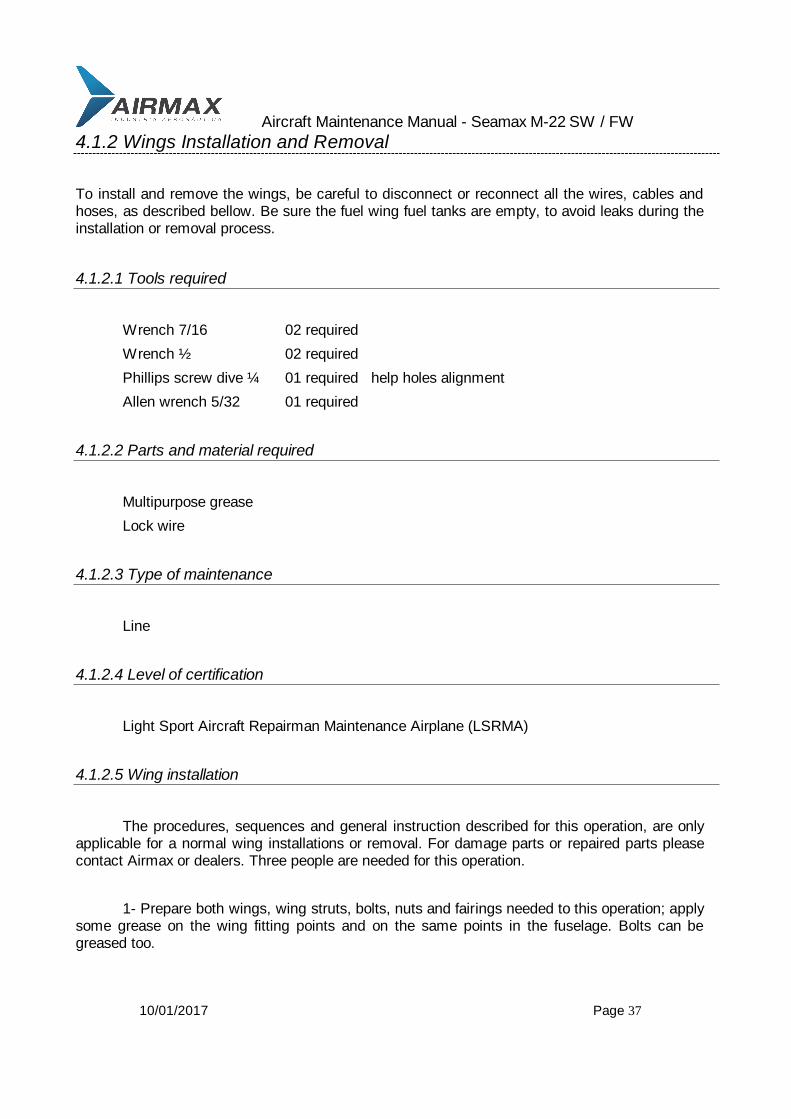
2- Place the fuselage, and block the wheels to avoid undesirable movements of the airplane during wing installation or removal;
3- Install on fuselage both wing struts, using the proper bolt and the plastic saddles between the fuselage fittings. Install the wing strut fairings on the other end of the wing struts, and lay down this end until wing installation.
4- Place the wing near the fuselage, and insert the main wing fitting only one inch inside the fuselage fitting, leaving a space between the wing root and the fuselage;
5- At this point we only need one person holding the wing tip, and other below the wing near the root, preparing all the hoses, cables and electric wires that come from the wing, to the respective holes on the fuselage. Right wing has wires for landing lights, wires for strobe and navigation lights, transponder cables and two steel cables for aileron mechanical system.

Aircraft Maintenance Manual - Seamax M-22 SW / FW
10/01/2017 Page 39
6- After al cables, hoses and wires are passing throw his correct places, force the wing to fit both connection on places, the front one already with one inch inside, and the rear one. Do not worry if wing does not seam to fit in fuselage, because of a gap between.
7- Connect the wing strut to the wing and install the bolt. Since there is a gap between the fuselage and wing, the wing should appear a negative dihedral.
8- Force the wing tip up, and the gap between the wing and the fuselage should be closed. From the inside part of the cabin, use (if necessary) the ¼ Philips screwdriver to align the holes of the main wing fitting, and place the bolt. Only this bolt and the wing strut will keep the wing in place. Be careful to avoid front movement on the wing tip. Install at the rear fitting point, threw the rear inspection holes on the top of fuselage. If necessary force the wing tip toward the and back.
9- Repeat the same procedures for the other side of the wing, and then install all the nuts in they bolts and torque them. Total of bolts to torque:
- 04 ¼, inside the fuselage, wing/fuselage attaching points
- 04 5/16, on each end of wing struts.
10- Start connecting aileron cables from inside the cabin. Connect the longest and rear ones to the torque tube belcranck arm, then thru pulleys located in the top of the cabin. The turnbuckles should be connected on the inside hole, using an AN3 bolt/nut.
NOTE: The right wing cable connects at the left belcranck arm after passing thru the pulley.

Aircraft Maintenance Manual - Seamax M-22 SW / FW
10/01/2017 Page 40
Connect both front ailerons cables to each other. Check proper ailerons cable and belcranck regulations. Check aileron neutral position. Use wire lock in all turnbuckles after the ailerons system is properly regulated.
11- Connect the strobe lights to the central unit located in the middle of the airplane. Connect the navigation light plugs to the cables with the same color located near the central unit. Connect the landing lights plugs.
After all connections are made, secure all cables along the structure tubes with tie-up clamps to avoid contact with any moving parts.
12- Connect the fuel hoses by feeding one line in each side, and two vent lines in each side. This gravitational fuel line can be secured on the connection with tie-up clamps. If necessary, affix with tie-ups to ensure that none of the fuel lines touch any part that can damaged.
13- Connect the transponder antenna cable at left side, and secure it with tie-ups.
14- Connect the pitot tube at right side of the cabin.
15- From outside the aircraft, reach through the rear top inspection window, and connect the ball joint to the ailerons after applying some grease. Connect one safety pin in each ball joint. Be sure to correctly install all safety pins. Check the flap alignment in a neutral position. Replace the inspection window by gluing it with silicon. Apply a vinyl seal over the seam.
16- Install the wing tip floats to their corresponding sides. Don’t forget to install the fairing on the float strut before installing it on the wing. Install the bolt and the nut.
17- Install the pitot tube inside the plastic base on the bottom part of the right wing.
18- With the fuel valves closed, put fuel in both fuel tanks. Check for leaks. Open one valve at a time, and check it is flowing to the heater tank. Fill the fuel system, and look for potential leaks.
4.1.2.6 Wing removal
The first step to removing the wings, is to empty the fuel tanks.
Once the fuel tanks are empty, proceed with the wing removal in the reverse sequence of installation.
4.1.2.7 Verification required
Check all bolts and nuts.
Check the fuel system, looking for leaks and odors.
Check the pitot and transponder antenna.
Check the landing, strobe, and navigation lights.
Check the flap and aileron control system.

Aircraft Maintenance Manual - Seamax M-22 SW / FW
10/01/2017 Page 41
4.2 Tail
The Seamax M-22 tail has a fin, rudder, and a stabilator installed on two half’s. The fin is made of composite. It is part of the fuselage, and where the stabilator mechanical system is fixed. The udder will be detailed later on control surfaces.
4.2.1 Stabilator Installation and Removal
4.2.1.1 Tools required
Wrench ½ 02
Allen wrench xx 01
Pliers 01
Aircraft Maintenance Manual - Seamax M-22 SW / FW
10/01/2017 Page 42
4.2.1.2 Parts and material required
Grease and Loctite 277
4.2.1.3 Type of maintenance
Line Airplane
4.2.1.4 Level of certification
Light Sport Repairman Maintenance (LSRMA)
4.2.1.5 Stabilator installation
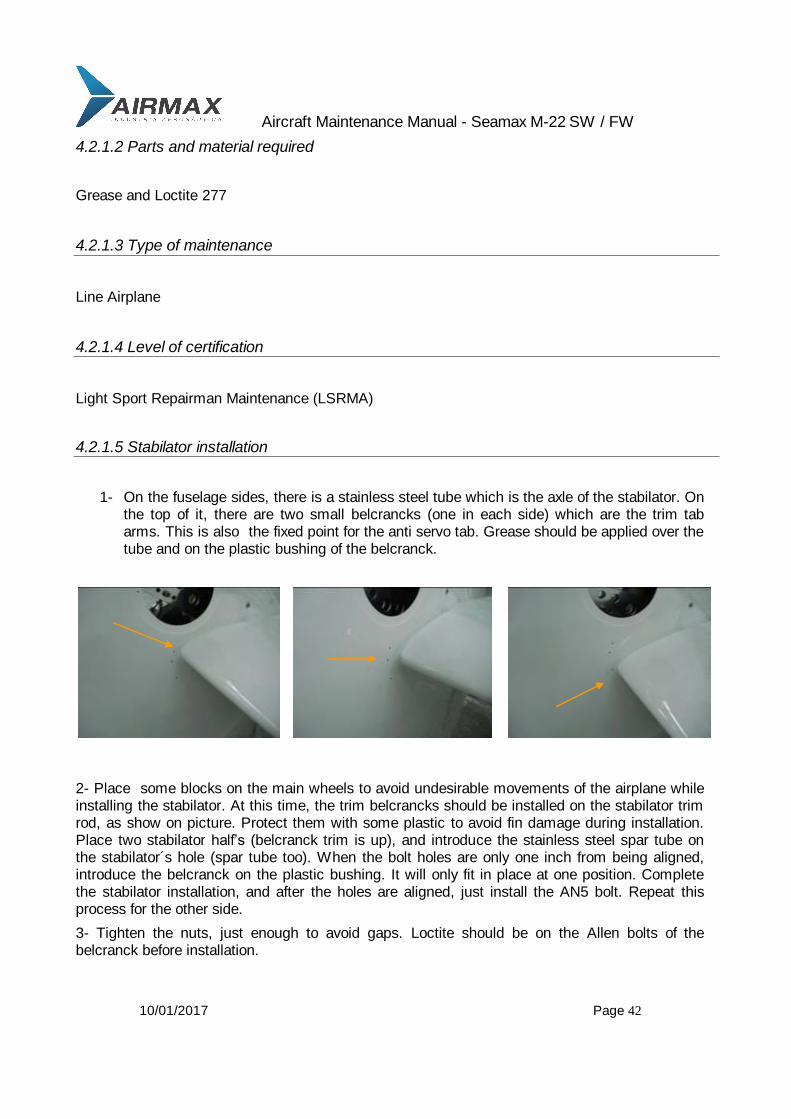
1- On the fuselage sides, there is a stainless steel tube which is the axle of the stabilator. On the top of it, there are two small belcrancks (one in each side) which are the trim tab arms. This is also the fixed point for the anti servo tab. Grease should be applied over the tube and on the plastic bushing of the belcranck.
2- Place some blocks on the main wheels to avoid undesirable movements of the airplane while installing the stabilator. At this time, the trim belcrancks should be installed on the stabilator trim rod, as show on picture. Protect them with some plastic to avoid fin damage during installation. Place two stabilator half’s (belcranck trim is up), and introduce the stainless steel spar tube on the stabilator´s hole (spar tube too). When the bolt holes are only one inch from being aligned, introduce the belcranck on the plastic bushing. It will only fit in place at one position. Complete the stabilator installation, and after the holes are aligned, just install the AN5 bolt. Repeat this process for the other side.
3- Tighten the nuts, just enough to avoid gaps. Loctite should be on the Allen bolts of the belcranck before installation.
Aircraft Maintenance Manual - Seamax M-22 SW / FW
10/01/2017 Page 43
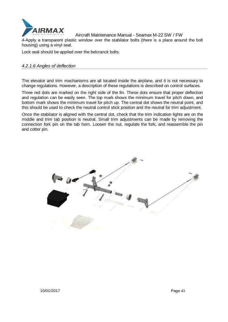
4-Apply a transparent plastic window over the stabilator bolts (there is a place around the bolt housing) using a vinyl seal.
Lock seal should be applied over the belcranck bolts.
4.2.1.6 Angles of deflection
The elevator and trim mechanisms are all located inside the airplane, and it is not necessary to change regulations. However, a description of these regulations is described on control surfaces.
Three red dots are marked on the right side of the fin. These dots ensure that proper deflection and regulation can be easily seen. The top mark shows the minimum travel for pitch down, and bottom mark shows the minimum travel for pitch up. The central dot shows the neutral point, and this should be used to check the neutral control stick position and the neutral for trim adjustment.
Once the stabilator is aligned with the central dot, check that the trim indication lights are on the middle and trim tab position is neutral. Small trim adjustments can be made by removing the connection fork pin on the tab horn. Loosen the nut, regulate the fork, and reassemble the pin and cotter pin.
Aircraft Maintenance Manual - Seamax M-22 SW / FW
10/01/2017 Page 44
4.2.1.7 Verification of stabilator installation and adjustment
Check the stabilator movement for play, smooth travel and unusual sounds. Check minimum and complete travel. Check neutral position of control stick and stabilator.
Check bolts and pins.
4.3 Landing Gear
As a sea plane, the Seamax M-22 landing gear is a repositionable tricycle that is activated powered by a electric motor. Lock down is made by an off center hinge located on the three legs. The electric system activates the three landing gears at the same time.
4.3.1 Front landing gear
4.3.1.1 Tools required
Allen wrench (5/16)
Allen wrench (1/4)
Allen wrench (3/16)
Allen wrench (5/32)
Wrench 7/16
Wrench 3/8
Pliers, fine point
Jack for retraction test
Philips screw driver
4.3.1.2 Materials required
Grease
Loctite 277
Vaseline
Safety wire
Aircraft Maintenance Manual - Seamax M-22 SW / FW
10/01/2017 Page 45
4.3.1.3 Type of maintenance
Line
4.3.1.4 Level of certification
Light Sport Repairman Maintenance Aircraft (LSRMA)
4.3.1.5 General
To remove, inspect, or install the front landing gear, the tail must be set down. Install some support just below the front wheel and below the keel to prevent the airplane from falling down on front wheel. Also install some blocks on the main wheels to avoid undesirable airplane movement.
If the landing gear retraction system will be inspected, place the entire aircraft on the special jack.
Install a support bellow the keel, and MAKE SURE that none of the wheels will touch the ground.
4.3.1.6 Inspections
Check for general conditions of the tires, tire pressure, and arm and shock absorber legs. Also check the fairing conditions.
4.3.1.6.1 Arm / fork inspection
Check for cracks or damaged points. Check the lateral play of the arm over the retraction hinge by forcing it sideways with your hand. Check the swivel travel of fork, movement, and neutral position by spring loading.

Aircraft Maintenance Manual - Seamax M-22 SW / FW
10/01/2017 Page 46
4.3.1.6.2 Shock absorber inspection
Before placing the airplane on a jack, inspect the position of the limit travel bolt with the Airplane on ground. With no load inside, the limit travel bolt should not be more than 3 mm after the bottom limit of the telescopic leg. Check the rubber/aluminum disks if it is more than 3 mm.
Force the nose down to check the telescopic movement.
4.3.1.6.3 Retract system inspection
With the airplane on jack, as described in 4.3.1.5, turn on the master switch, and place the landing gear switch up to the “on” position. Check for travel, unusual noises, and smooth movement. Check that the “up” and “down” positions are correct. Check for free movement of the hinges on the center lock by pulling gently with your hand. You must be able to move the hinge more than zero and less than ¼ inches. If not, tune the retraction limits as described on 4.3.2.10.

Aircraft Maintenance Manual - Seamax M-22 SW / FW
10/01/2017 Page 47
4.3.1.7 Front landing gear Removal / installation
Unless specified, the installation process will be the reverse sequence of removal. Special details on installation will be described.
4.3.1.7.1 Wheel and fork removal / installation
To remove the complete set of wheel and fork, first remove the front wheel fairing by unscrewing the four screws on the front wheel arm. Remove the neutral position spring.
Remove the bolt / nut on the top of the fork axle, and remove cap. Swivel it and push it down and the complete set of wheel and fork will come out.
Unscrew at least one of the two bolts on the top of the wheel axle. Pull from the side with the bolt /washer and the axle can be removed. The front wheel will be out of the fork.
4.3.1.7.2 Shock absorber removal / installation
Use needle nose pliers to remove the cotter pin that connects the telescopic leg to the carbon fiber arm.
From inside the cockpit, remove the four springs (for locking up and down position).
The teleflex cables should be removed from their place by cutting the safety wire. Then slide them out of the support.
Aircraft Maintenance Manual - Seamax M-22 SW / FW
10/01/2017 Page 48
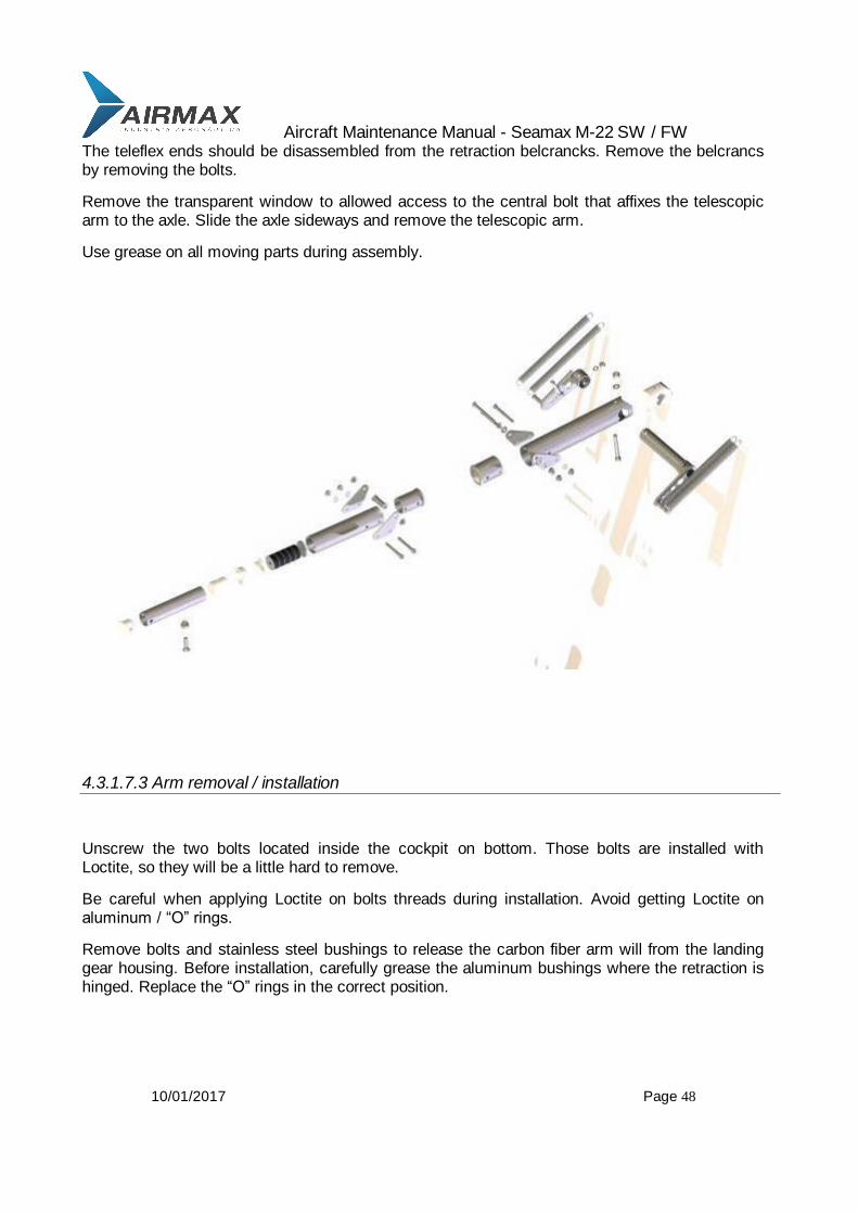
The teleflex ends should be disassembled from the retraction belcrancks. Remove the belcrancs by removing the bolts.
Remove the transparent window to allowed access to the central bolt that affixes the telescopic arm to the axle. Slide the axle sideways and remove the telescopic arm.
Use grease on all moving parts during assembly.
4.3.1.7.3 Arm removal / installation
Unscrew the two bolts located inside the cockpit on bottom. Those bolts are installed with Loctite, so they will be a little hard to remove.
Be careful when applying Loctite on bolts threads during installation. Avoid getting Loctite on aluminum / “O” rings.
Remove bolts and stainless steel bushings to release the carbon fiber arm will from the landing gear housing. Before installation, carefully grease the aluminum bushings where the retraction is hinged. Replace the “O” rings in the correct position.

Aircraft Maintenance Manual - Seamax M-22 SW / FW
10/01/2017 Page 49
4.3.2 Main landing gear
4.3.2.1 Tools required
Allen wrench (5/16)
Allen wrench (1/4)
Allen wrench (3/16)
Pliers
Wrench 5/16
Wrench 7/17
Wrench 3/8

Aircraft Maintenance Manual - Seamax M-22 SW / FW
10/01/2017 Page 50
4.3.2.2 Materials required
Grease
Loctite 277
Vaseline
Safety wire
4.3.2.3 Type of maintenance
Line
4.3.2.4 Level of certification
Light Sport Repairman Maintenance Aircraft (LSRMA)
4.3.2.5 General
To remove, inspect or install the main landing gear, place the aircraft on the special jack. Install a support bellow the keel, and make sure that none of the wheels will touch the ground, when the landing gear is deployed in a downward position.
4.3.2.6 Inspections
Perform a visual inspection to look for unscrewed bolts, oil brake leaks, general conditions of fairings, and position of travel limit of shock absorber leg.
A visual check of wheels position on ground can show main landing gear damage by looking for visual caster of main wheels. If the main wheels are with the negative caster, (more than 5 degrees) check the of limit travel or if the main landing gear arm is bent.
Aircraft Maintenance Manual - Seamax M-22 SW / FW
10/01/2017 Page 51
4.3.2.6.1 Arm inspection
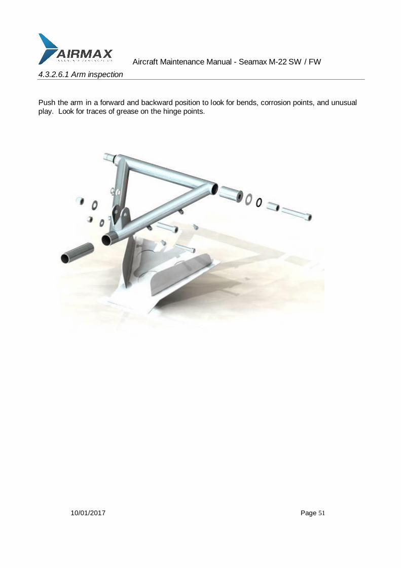
Push the arm in a forward and backward position to look for bends, corrosion points, and unusual play. Look for traces of grease on the hinge points.
Aircraft Maintenance Manual - Seamax M-22 SW / FW
10/01/2017 Page 52
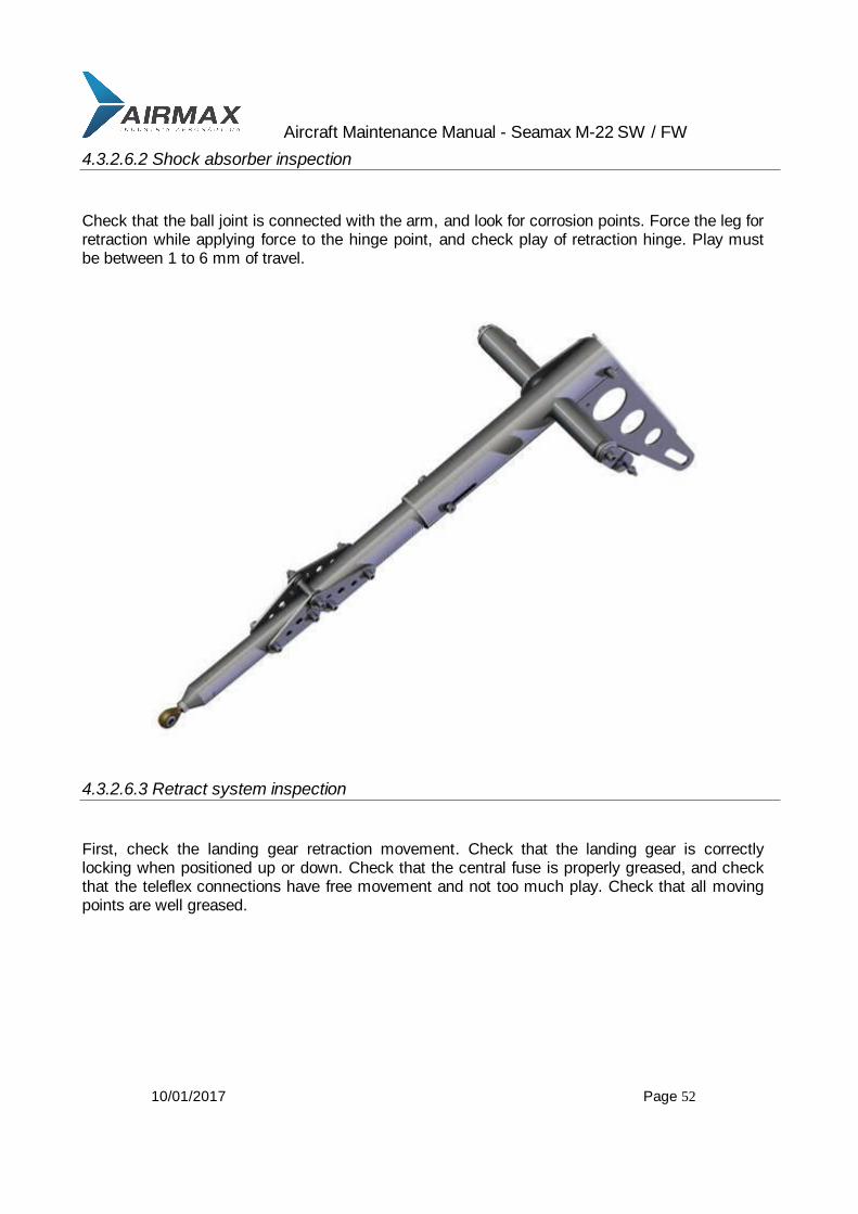
4.3.2.6.2 Shock absorber inspection
Check that the ball joint is connected with the arm, and look for corrosion points. Force the leg for retraction while applying force to the hinge point, and check play of retraction hinge. Play must be between 1 to 6 mm of travel.
4.3.2.6.3 Retract system inspection
First, check the landing gear retraction movement. Check that the landing gear is correctly locking when positioned up or down. Check that the central fuse is properly greased, and check that the teleflex connections have free movement and not too much play. Check that all moving points are well greased.
Aircraft Maintenance Manual - Seamax M-22 SW / FW
10/01/2017 Page 53
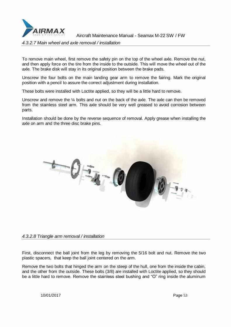
4.3.2.7 Main wheel and axle removal / installation
To remove main wheel, first remove the safety pin on the top of the wheel axle. Remove the nut, and then apply force on the tire from the inside to the outside. This will move the wheel out of the axle. The brake disk will stay in its original position between the brake pads.
Unscrew the four bolts on the main landing gear arm to remove the fairing. Mark the original position with a pencil to assure the correct adjustment during installation.
These bolts were installed with Loctite applied, so they will be a little hard to remove.
Unscrew and remove the ¼ bolts and nut on the back of the axle. The axle can then be removed from the stainless steel arm. This axle should be very well greased to avoid corrosion between parts.
Installation should be done by the reverse sequence of removal. Apply grease when installing the axle on arm and the three disc brake pins.
4.3.2.8 Triangle arm removal / installation
First, disconnect the ball joint from the leg by removing the 5/16 bolt and nut. Remove the two plastic spacers, that keep the ball joint centered on the arm.
Remove the two bolts that hinged the arm on the steep of the hull, one from the inside the cabin, and the other from the outside. These bolts (3/8) are installed with Loctite applied, so they should be a little hard to remove. Remove the stainless steel bushing and “O” ring inside the aluminum

Aircraft Maintenance Manual - Seamax M-22 SW / FW
10/01/2017 Page 54
base on the fuselage structure. The stainless steel should be very well greased, but avoid grease contact with bolts when assembling.
During the installation process, grease the bushings, apply Loctite to the bolts, screw in both bolts, and check travel for free swiveling.
4.3.2.9 Shock absorber leg removal/installation
Disconnect the ball joint from inside the cockpit as described in the last step. Then, disconnect the Teleflex fittings on both sides by removing the 3/16 bolts on the retraction aluminum arm.
Disconnect the end of the retraction arm from the retraction mechanism by removing the safety pin and washers. Remove the safety wire, and remove the four bolts that keep the big hinge pins on the leg hinge point. Twist the protection plates, and remove the two big aluminum pins from each side of the safety mechanical breaker axle. The leg will drop down by the hole of main landing gear arm. If necessary use the bolts to remove the big aluminum pins.
The landing gear arm is affixed to the leg by the safety mechanical breaker axle and a bolt with bushing that allows travel between the leg and arm. If necessary remove this bolt to completely bend the arm into leg direction.
Installation is exactly at the reverse sequence of removal.
Make sure to apply grease in all moving parts.
Teleflex connection on the retraction arm should allow a free travel with out much play
4.3.2.10 Retraction system tuning
First disconnect both Teleflex on the main landing gear retraction arm or on the front landing gear belcranck. (These Teleflex will synchronize the front landing gear with main landing gear.
With the airplane on a jack, move the main landing gear to and up and down position to check the landing gear lock. The lock positions are determined by the position of the micro switch on the retraction mechanism. Lock down should allow a travel from 1 to 8 mm on the main landing gear legs, forcing the leg hinge to the inside. Values greater or lower than limits, requires a micro switch adjust tuning.
Check travel and lock position of the main landing gear before proceeding to the front landing gear tuning.
With the landing gear down, connect Teleflex with grease. The hinge bolt should allow a free movement of the fitting. Screw the bolt to the limit and then unscrew a half turn.
Adjust the Teleflex fitting at proper length, to assure front landing gear lock down.
Forcing the front landing gear retraction hinge, a free movement should be allowed from 1 to 5 mm.

Aircraft Maintenance Manual - Seamax M-22 SW / FW
10/01/2017 Page 55
Adjust the Teleflex fitting length to have those limits.
After all systems are connected, recheck movements, and lock up and down.
4.3.3 Brakes
4.3.3.1 Tools required
Allen wrench (1/4)
Allen wrench (3/16)
Wrench 7/16

Aircraft Maintenance Manual - Seamax M-22 SW / FW
10/01/2017 Page 56
4.3.3.2 Materials required
Fluid for brake system, (not braking fluid)
Loctite 277
Nylon ¼ high pressure tubing
4.3.3.3 Type of maintenance
Line
4.3.3.4 Level of certification
Light Sport aircraft Repairman Maintenance Aircraft (LSRMA)
4.3.3.5 General
The Seamax M-22 braking system consists of two independent hydraulic lines; one for the right wheel, and other for the left wheel. It is a differential brake system which allows you to make turns with the airplane on ground.
The brake pedals and toe brakes can be controlled by both the pilot and passenger.
The brake system has two brakes cylinders for each wheel. These can also be controlled by both the pilot and the passenger.
The oil tank feeds both hydraulic lines, and it is located behind the panel in the middle of the cockpit.

Aircraft Maintenance Manual - Seamax M-22 SW / FW
10/01/2017 Page 57
4.3.3.6 Inspection
A visual inspection can be done on the complete system checking for:
- Check for leaks on the tubing ends and fittings and over the brake cylinders.
-Check the oil level in the tank.
- Check the general conditions of the nylon tubing, especially near the main landing gear which is the articulated system for retraction. Check protection and fixation points.
- Check the general conditions of disk brakes. Check for corrosion, and make sure there is free movement along the axle direction on the three point of connection.
While taxiing the airplane, check for unusual noises and correct brake response while turning left and right.
Aircraft Maintenance Manual - Seamax M-22 SW / FW
10/01/2017 Page 58
4.3.3.7 Filling the system with oil
After replacing the nylon tubing, follow these steps to fill all system with oil:
- Place the airplane on a jack so that the main wheels are off the ground. The front wheel can stay on ground.
- Remove the main landing gear fairing and axle fixation bolt (see sequence 4.3.2.7) to allow the axle to swivel. It just needs to rotate to be enabling easier oil filling.
- Rotate the axle 180 degrees to keep the oil filling cap up (original position is down).
- Remove the oil cap (1/8 NPT cap) and insert the filling terminal to feed the hydraulic line.
- Return the axle to the original position, and with filling cap down, insert a syringe to fill oil. The oil should be filled with the terminal at down position to allow all the air be removed from the line with new oil.
- Fill the oil until it arrives at the central oil tank.
- Once all system is filled, turn axle to place the fill fitting to up an position again. Remove the fill fitting. Complete with oil, and install the oil cap always with this side up.
- Replace with oil cap down and proceed to the assembly process.
- Check all system for leaks, air bubbles in oil line, and system operation.
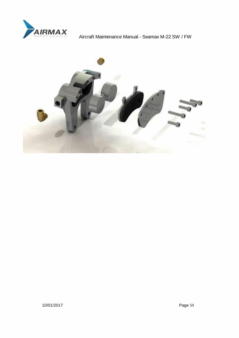
4.3.3.8 Brake pad replacement
To change the brake pads, place the airplane on the jack, to prevent the main wheels from touching ground. The front wheel can stay on ground.
Remove the wheel as described on 4.3.2.7. The disk brake will stay in between the brake calipers.
Remove the six 3/16 bolts on brake calipers, to release the disc brake and the disk pads.
Replace the disk pads and reassemble in the reverse way.
Aircraft Maintenance Manual - Seamax M-22 SW / FW
10/01/2017 Page 59
Aircraft Maintenance Manual - Seamax M-22 SW / FW
10/01/2017 Page 60
4.4 Control Surfaces
4.4.1 Ailerons
4.4.1.1 Tools required
Allen wrench (3/16)
Allen wrench (1/4)
Wrench 7/16
Wrench 3/8
Wire cutter pliers
4.4.1.2 Materials required
Grease
Safety wire
Lock seal
Vinyl inspection window seal
4.4.1.3 Type of maintenance
Heavy
4.4.1.4 Level of certification
Light Sport aircraft Repairman Maintenance Aircraft (LSRMA)
Aircraft Maintenance Manual - Seamax M-22 SW / FW
10/01/2017 Page 61
4.4.1.5 General
The aileron control system consists of two different mechanisms:
-The first part is made of stainless steel cables and closed circuit pulleys which run from the torque tube to the belcrancks inside the wing. The ailerons are connected to the belcrancks by a push-pull tube with two rods ends in each end. These rods ends have left and right, to fine adjustments.
If necessary, first adjust the close circuit control cables by adjusting the three turnbuckles. Two of turnbuckles are connected on the torque tube, and other on the top of the cockpit. This adjustment must keep the two wings belcrancks parallel to each other, and maintain a constant tension on the cable circuit.
The aileron neutral position is adjusted by turning the connection rods, after unscrewing the lock nuts. The vinyl inspection window should be removed for this operation
4.4.1.6 Inspection
Inspect the general condition of aileron, fabric, and paint conditions. Check the hinge brackets, hinge plastic bushings, and hinge bolts.
Check the connection rods conditions to see if they have a normal travel, and are properly greased.
Check also the cable circuit, turnbuckles, and pulleys. Check cable tension.
4.4.1.7 Aileron removal/installation
To remove the aileron from the wing, first remove the ¼ bolt that connects the rod to the aileron. After, cut the safety wires on the hinge bolts, and remove them. Assembly is done in the reverse sequence. Check that there is no metal to metal movement on the aileron hinge. A plastic bushing should always contact the metal parts. Properly greases, and use safety wire on hinge bolts.
If the wing needs to be removed, disconnect the three turnbuckles inside the cockpit, and remove them from the pulleys located on top of the cockpit.

Aircraft Maintenance Manual - Seamax M-22 SW / FW
10/01/2017 Page 62
4.4.1.8 Aileron setting
As described on 4.4.1.5, close circuit of control cables should be adjusted at first.
The wing belcrancks should be parallel to the centerline of the fuselage, regarding the two pins holes where cables are attached. This adjustment is done by twisting the turnbuckles up to achieve the correct position. The turnbuckles on the tube should be connected on the inside holes.
Put the control stick in neutral position, and then turn the connection rods up so that the ailerons are aligned with the bottom surface of the wing. Use a ruler near the first hinge point to find the correct position.
Then set the ailerons on a correct position, and screw the lock nuts on the rods ends. Use lock
seal to perform a visual check.
In-flight fine tuning can be made by bending or installing a tab that can be glued to the aileron’s trailing edge. Bend it up to have an in flight aileron neutral position.
4.4.1.9 Aileron verification and adjustment
Check all mechanical circuits for unscrewed bolts or nuts, and missing safety wire.
Check free and smooth travel, and look for unusual noises.
Check the hinges and hinge brackets. Check that all moving parts are well greased and locked.
Check the ailerons neutral point with neutral control stick.
Aircraft Maintenance Manual - Seamax M-22 SW / FW
10/01/2017 Page 63
4.4.2 Flaps
4.4.2.1 Tools required
Allen wrench (3/16)
Wrench 3/8
Wire cutter pliers
Pliers
Small screwdriver
4.4.2.2 Materials required
Grease
Safety wire
Lock seal
Silicon
Vinyl plastic seal for inspection windows
4.4.2.3 Type of maintenance
Heavy
4.4.2.4 Level of certification
Light Sport aircraft Repairman Maintenance Aircraft (LSRMA)

Aircraft Maintenance Manual - Seamax M-22 SW / FW
10/01/2017 Page 64
4.4.2.5 General
The Seamax M-22 flaps are activated by a single electric motor.
The flap’s deflection limits are made by two micro switches (big ones), one on the top and other
on the bottom of the flap activator.
Small micro switches are used to provide the position information on the dashboard. It is indicated by five LED lights, one red on the top, and four greens on the bottom.
The red led indicates flap negative positions, the four green led lights indicates flap deflection from 0 degrees to 35 degrees. If there is no led light, it indicates a neutral position.
The flaps deflection can also been seen through the lateral window during flight.
If the micro switches malfunction, the electric activator has a clutch to avoid over load.
4.4.2.6 Inspection
Inspect the general condition of flaps, fabric, and paint. Check the hinge brackets, plastic bushings, and bolts.
Check travel, limits, and led light indicators. Check for unusual play and noises during flap travel.

Aircraft Maintenance Manual - Seamax M-22 SW / FW
10/01/2017 Page 65
4.4.2.7 Flaps removal/installation
Remove the four inspections windows on the top of fuselage to allow access to the flap connection.
Remove the safety clip on the flap ball joint.
Remove the safety wire on flap hinges, and then remove the flaps.
Assembly is done the reverse sequence .Use grease on the ball joint connection.
4.4.2.8 Flaps setting
The Seamax M-22 flap has a negative position for cruise. In a negative position a red LED will light in the flap indicator on the instrument panel. A negative deflection should not be more than 5 degrees. This adjustment is made by repositioning the bottom micro switch on the activator.
The neutral point is set when the flap trailing edge is aligned with fuselage trailing edge. This negative point is zero degrees, and no led lights should be lit.
The full flap limit is also set by the upper activator micro switch. The full flap should not be more than 35 degrees.

Aircraft Maintenance Manual - Seamax M-22 SW / FW
10/01/2017 Page 66
4.4.2.9 Flaps verification and adjustment
Check travel and flap limits.
If the flaps are not at the same position, remove one of the ball joint connections. Then unscrew the lock nut on the female ball joint part, and twist it or untwist as desirable for adjustments.
Once at the correct position, screw the lock nut, re-grease, and install the safety clip.
Check the hinges and hinge brackets.
4.4.3 Rudder
4.4.3.1 Tools required
Allen wrench (3/16)
Allen wrench (1/8)
Wrench 3/8
Pliers
4.4.3.2 Materials required
Grease
Torque seal
Safety wire
Vinyl inspection window seal
4.4.3.3 Type of maintenance
Heavy

Aircraft Maintenance Manual - Seamax M-22 SW / FW
10/01/2017 Page 67
4.4.3.4 Level of certification
Light Sport aircraft Repairman Maintenance Aircraft (LSRMA)
4.4.3.5 General
The rudder is activated by stainless steel control cables. The control cables are connected to the rudder pedals with turnbuckles that provide a fine adjustment.
A central fairing inside the cockpit should be removed to access the two turnbuckles.
With normal use, those turnbuckles should be adjusted to the normal cable tension, and the rudder pedals should be in the correct position.
4.4.3.6 Water rudder removal / installation
To remove the water rudder, first remove inspection window located ion the left side, in the rear part of the fuselage.
Hold the water rudder in the retracted position with some tape, and then set the lever to the down position (on central console). Unscrew the two allen bolts, and disconnect the fitting though the inspection window.
Carefully unscrew the four bolts on the aluminum fittings inside the lower part of the rudder that
keep the retraction bushings in place. Pay ATTENTION to the spring load pressure.
Remove the two fittings and the water rudder can be removed. Gently pull the retraction cable.
Assembly is done in the reverse sequence. Grease the retraction cable, and be careful of the spring pressure when assembling the two fittings with bolts.

Aircraft Maintenance Manual - Seamax M-22 SW / FW
10/01/2017 Page 68
Start inserting the water rudder in a down position so that it fits in the housing. Turn it on in the retracted position and keep the pressure to prevent spring loading.
4.4.3.7 Rudder removal / installation
Remove or disconnect the water rudder retraction cable, as described on 4.4.3.6. It is not necessary to fully remove the water rudder unless it is necessary to perform maintenance or make an inspection.
To ease the removal of the rudder cables, disconnect the four springs on the rudder pedals.
Remove the clevis pins and pins on the rudder bracket. Pay attention to the plastic bushings.
Remove the safety wires and nuts on the hinge bolts.
Remove the bolts and rudder. Pay attention to the plastic hinge bushings.
Assembly is made the reverse sequence. Make sure to place the plastic bushing between to prevent metal to metal movements.

Aircraft Maintenance Manual - Seamax M-22 SW / FW
10/01/2017 Page 69
4.4.3.8 Rudder adjustment
To adjust the rudder to neutral position, put the rudder pedals in neutral position, and adjust the two turnbuckles.
The pedals must be aligned and be at least one inch far from the front wheel housing.
In-flight adjustments should be made by bending the trim tab located at the end of the rudder.
4.4.3.9 Rudder verification and Adjustments
Check the general rudder condition for cracks and damage to the paint.
Check free travel, make sure there is grease on the hinges and control cables, and that the pedals are in neutral position.
Check for smooth travel and unusual sounds.
Aircraft Maintenance Manual - Seamax M-22 SW / FW
10/01/2017 Page 70
5. Engine
The engine manuals for the Rotax engine are issued by Rotax, and supplied with the Seamax M-22. These manuals are: - The Operator’s Manual for all versions of Rotax 912 - The Maintenance Manual for Rotax 912 series (Line maintenance). - The Maintenance Manual II for Rotax 912 series (Heavy maintenance). NOTE: Removal and installation of the engine can only be done by a Seamax authorized service center, or by an authorized A&P mechanic. Since the Seamax M-22 has a pusher engine, one must be very careful to avoid forgetting any tools, parts, or objects loose inside the engine cowling. This is especially important because while the engine runs, these objects can move toward the turning propeller, and cause damage or accidents.

Aircraft Maintenance Manual - Seamax M-22 SW / FW
10/01/2017 Page 71
6 Fuel System
6.1 General
The fuel system inspection should be performed in a well ventilated area away from heaters or flames.
The Seamax M-22 fuel system consists in two wing fuel tanks and one central header tank.
Both wing fuel tanks feed the central header tank by gravity. From the heater tank, the fuel goes to the engine mechanical fuel pump through a fuel filter and an electric fuel pump as shown in fig 26. The header tank is located behind the luggage compartment.
Aircraft Maintenance Manual - Seamax M-22 SW / FW
10/01/2017 Page 72
6.2 Tools Required
Cutting pliers
Wrench 7/16
Knife
Philips screwdriver
Allen wrench (1/4)
6.3 Materials Required
Transparent silicon fuel hose
½ metallic clamps
Plastic clamp
Tire ups
Silicon rubber
6.4 Type of Maintenance
Line
6.5 Level of Certification
Light Sport Aircraft Repairman Maintenance Airplane (LSRMA)
6.6 Fuel System Inspection Check List
1 Inspect fuel caps, check fuel cap seals and key operation, check for smoothness. Check the general conditions of the fuel cap.
2 From inside the cockpit, inspect all the plastic connections to the fuel tanks, and look for leaks and loose clamps.
Aircraft Maintenance Manual - Seamax M-22 SW / FW
10/01/2017 Page 73
3 Inspect all the fuel hoses for general conditions, cracks, and hose rigidity. Check that the hoses are well fixed to avoid contact with other parts and moving parts
4 Check the fuel filter. Empty the header tank, close both fuel valves from the wing tanks, and open the drain valve before removing the fuel filter. Replace each year or each 100 H.
5 Drain the header tank to check the water and fuel quality.
6 Check the fuel pump, fuel pump connections, and fuel pump fixation.
7 Inside the engine cowling, check the fire sleeve protection on fuel hoses. Check the fuel circuit inside the cowling.
8 Check the fuel vents inside the engine cowling.
6.7 Fuel Filter
Check the fuel filter for foreign objects and cleanliness. Replace each 100 h or each year. Do not use paper fuel filters. Consult the Rotax manual for fuel filter information.
6.8 Fuel Vents
The Seamax has five fuel vents; two for each wing’s tank, one in each side of fuel tank, and one from the header tank.
All the five fuel vents go to the engine cowling, the highest part of the airplane, protected inside with fire sleeve.
6.9 Removal / Installation of Wing Fuel Tanks
Before removing a wing fuel tank, first empty the entire fuel system by opening both fuel valves and drain the fuel.
Disconnect the fuel line and the two fuel vents from each fuel tank.
Remove the wing following the instruction described in 4.1.2.5.
Use a knife to cut the silicon that goes between the side of the fuel tank and the wing.
Remove the fuel cap and unscrew the six Philips screws on the tank intake. Remove the tank intake and be careful to prevent the “O” ring from falling inside the tank .
Through the inspection window on the bottom of the wing, disconnect the fuel drain.
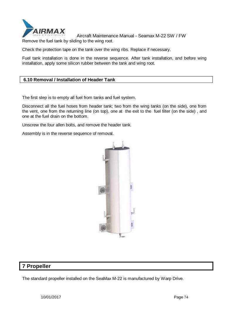
Aircraft Maintenance Manual - Seamax M-22 SW / FW
10/01/2017 Page 74
Remove the fuel tank by sliding to the wing root.
Check the protection tape on the tank over the wing ribs. Replace if necessary.
Fuel tank installation is done in the reverse sequence. After tank installation, and before wing installation, apply some silicon rubber between the tank and wing root.
6.10 Removal / Installation of Header Tank
The first step is to empty all fuel from tanks and fuel system.
Disconnect all the fuel hoses from header tank; two from the wing tanks (on the side), one from the vent, one from the returning line (on top), one at the exit to the fuel filter (on the side) , and one at the fuel drain on the bottom.
Unscrew the four allen bolts, and remove the header tank.
Assembly is in the reverse sequence of removal.
7 Propeller
The standard propeller installed on the SeaMax M-22 is manufactured by Warp Drive.
Aircraft Maintenance Manual - Seamax M-22 SW / FW
10/01/2017 Page 75
The leading edges of the blades are protected with a metallic strip to minimize erosion due to water spray contact.
Manufacturer ..................................................... WarpDrive Diameter ........................................................... 68” - 172 cm (maximum) Number of Blades .............................................. 3 Type.................................................................. ground adjustable Maximum RPM .................................................. 2800
7.1 Type of Maintenance
Line and repair
Check on the manufacturer maintenance manual to check what maintenance must be performed on the propeller.
7.2 Level of Certification
Light Sport Repairman Maintenance Aircraft (LSRMA) - which holds a FAA repairman certificate (LSA), with maintenance rating or equivalent (FAA A&P).
8 Instruments and Avionics
Seamax M-22 standard instruments are:

Aircraft Maintenance Manual - Seamax M-22 SW / FW
10/01/2017 Page 76
Airspeed
Altimeter
Vertical speed
Compass
Bank indicator
RPM
Oil pressure
Oil temperature
Water temperature
8.1 Tools Required
Screwdriver
Philips screwdriver
8.2 Parts Required
Tags (For marking wires if they are disconnected)
8.3 Type of Maintenance
Line
8.4 Level of Certification
Light Sport Aircraft Repairman Maintenance Airplane (LSRMA)
8.5 Maintenance
No special maintenance is required on the aircraft instruments. Instruments errors depend on operating conditions, as described in FAA-H-8083-15, chapter 3.

Aircraft Maintenance Manual - Seamax M-22 SW / FW
10/01/2017 Page 77
For particular maintenance, malfunction and special instructions, contact an instrument dealer, according to the specifications on the instruments manuals, supplied with the airplane.
Malfunction instruments can also be changed by other type or other manufacturer, by a Light Sport Aircraft Repairman Maintenance Airplane (LSRMA)
8.5.1 Airspeed
This instrument does not require maintenance. If required a special repair is needed, check instrument manuals for procedures on how to return the instrument to the manufacturer or authorized dealer.
An annual leak test should be performed on pitot lines.
Check proper fixation, and perform a visual check for general conditions.
8.5.2 Altimeter
This instrument does not require maintenance. If special repairs are required, check the instrument manuals for procedures on how to return the instrument to the manufacturer or authorized dealer.
Check proper fixation, and perform a visual check for general conditions.
8.5.3 Vertical Speed
This instrument does not require maintenance. If special repairs are required, check the instrument manuals for procedures how on to return the instrument to the manufacturer or authorized dealer.
Check proper fixation, and perform a visual check for general conditions.
8.5.4 Compass
Check the compass for proper fixation, and perform a visual check for general conditions. Check the liquid for air bubbles and leaks.
Aircraft Maintenance Manual - Seamax M-22 SW / FW
10/01/2017 Page 78
Check for deviation card and seal.
8.5.5 Bank Indicator
Check for proper fixation, and perform a visual check for general conditions.
8.5.6 RPM
Check for proper fixation, and perform a visual check for general conditions.
Check the accuracy once a year by measuring the propeller rpm with an optical device.
8.5.7 Oil Pressure
Check for proper fixation, and perform a visual check for general conditions.
Check the electric connections on the instrument and engine sensors.
8.5.8 Oil Temperature
Check for proper fixation, and perform a visual check for general conditions.
Check the electric connections on the instrument and engine sensors.
8.5.9 Water Temperature
Check for proper fixation, and perform a visual check for general conditions.
Check the electric connections on the instrument and engine sensors.

Aircraft Maintenance Manual - Seamax M-22 SW / FW
10/01/2017 Page 79
8.5.10 Flap Position Indication Light
Check the operation of the indication lights and micro switches on the flap motor. These lights are only for indication purposes, and are activated by the small micro switches.
8.6 Pitot Line and Static Port
The pitot line located on airspeed instrument should be inspected for obstruction at least once year.
The aluminum pitot tube located on the right wing can be easily removed from its plastic base by gentle pulling and turning. Check its fixation and position. Check the connection point near the wing root, where the line is disassembled during wing removal.
The static ports and the airspeed, altimeter and vertical speed have no special connection, and the static port is open to cockpit environment.
8.7 Special Instruments and Avionics
Special instruments and avionics, as a radio, transponder, GPS, glass instruments, gyro,
autopilot, etc, should follow special instruction described on the manufacturer manual that is
supplied with the airplane.
9 Electrical System
The wiring supplies electrical energy across the airplane inside a conduit tubing. This system, starting from the battery which is placed behind right seat. The wires run to the rear fuselage section to feed electric landing gear, electric flap, fuel pump and voltage regulator. One bilge pump, on the lower part of the hull has its own wiring.

Aircraft Maintenance Manual - Seamax M-22 SW / FW
10/01/2017 Page 80
A wiring enclosed in a conduit runs to the tail to feed electric trim and lights.
The basic electric panel is located on an upper console with switches and circuit breakers. The ignition key and master switch are also located on this console in the top between the seats.
Another electrical cable goes to the instrument panel where the electrical connection terminals for avionics and instruments are placed.
Inside, the engine cowling electric cables are protected with a fire sleeve.
9.1 Tools Required
Cutter pliers
6mm wrench
8 mm wrench
Philips screwdriver
Aircraft Maintenance Manual - Seamax M-22 SW / FW
10/01/2017 Page 81
9.2 Materials Required
plastic clamps
9.3 Type of Maintenance
Line
9.4 Level of Certification
Light Sport Aircraft Repairman Maintenance Airplane (LSRMA)
9.5 General
Remove the cockpit fairings to easily access the electrical cables. If necessary, remove any desirable inspection windows.
The top central panel can be removed by unscrewing bolts.
Disconnect the battery terminal if the airplane will be parked or stored in the hangar for a long period of time.
9.6 Inspection
Check the general condition of wires and cables.
Check the proper cables fixation to avoid contact with moving parts or sharp edges.
Check the electrical connection on studs, nuts, and bolts.
Perform a visual check for corrosion or damage on insulation points.
9.7 Battery Replacement
Remove the right seat to easily access the battery, open the battery case, disconnect the terminals, and replace the old battery with a new one.
Use only sealed batteries, which can fit inside the battery case.
Before replacing with a different type of battery, first consult Airmax or dealers for technical information.

Aircraft Maintenance Manual - Seamax M-22 SW / FW
10/01/2017 Page 82

Aircraft Maintenance Manual - Seamax M-22 SW / FW
10/01/2017 Page 83
9.8 Wiring diagram
1 1Monday, November 06, 2006
Title
Size Document Number Rev
Date: Sheet of
MASTER
SENSOR
S5
rpm
TURN COORDINATOR
water temp
NAV. TL.
RETIFIER
LANDING GEAR
PICK UP
SENSOR
S3
S6
BILDGE PUMP
oil pressure
S1
oil temp
LANDING LIGHTS
INST.
FUEL PUMP
SENSOR
S2
S4
VHF
TRANP.
STROB
RELE
STARTER
30A
BAT.
LAMP.
Wiring diagram
S7
GPS
5A
10A
5A
5A
10A
10A
5A
5A
10A
BAT
S R
LGNDMODULE
IGNITION
40A
G
G L
+B
C
ILUM.PAINEL
R
G
DIODE

Aircraft Maintenance Manual - Seamax M-22 SW / FW
10/01/2017 Page 84
10 Structural Repairs
10.1 Type of Maintenance
Repair
10.2 Level of Certification
Task can be completed only by a responsible individual who holds an FAA Repairman Certificate and who has gone through a structural repairing course by Airmax Construções Aeronáuticas Ltda.
Otherwise all structural repairs must be done at Seamax authorized service centers.

Aircraft Maintenance Manual - Seamax M-22 SW / FW
10/01/2017 Page 85
11 Painting and Coating
The Seamax M-22 uses polyurethane base paint and primer. Both are UV resistant and protect fiberglass and fabric against UV rays. Scratches or others defects on the paint over fiberglass parts, should be sanded up to the fiberglass. If the fiberglass is also damaged, refer to structural repairs. Parts covered with fabric including the wings, ailerons and flaps can be repaired with paint only if the fabric is not damaged.
11.1 Tools Required
Spray gun
11.2 Materials Required
Sand paper 320, 400, 600 and 1200
Putting PPG 1800
Primer PPG D830 FL
Primer catalyze PPG DF 863
Paint PPG Delfleet PE1AERM060
Paint catalyze PPG F 361
Solvent PPG 372
Polishing paste
11.3 Type of Maintenance
Heavy.
11.4 Level of Certification
Tasks can be completed only by a responsible individual who holds an FAA Repairman
Certificate and has received a painting training course by AIRMAX CONSTRUÇÕES
AERONÁUTICAS LTDA.
11.5 Putting
Aircraft Maintenance Manual - Seamax M-22 SW / FW
10/01/2017 Page 86
The surface must be prepared with sand paper grade 320 or up, on the area being repaired. Do not use sand paper to exposed fiberglass.
Use putting PPG 1800, use mixture 100 to 1 up to 100 to 3, depending of the cure time desired.
Let putting dry at least 30 to 50 minutes at 20 degrees C.
Use sand paper to smooth the surface, starting with 320 and finishing with 600.
11.6 Priming
After preparation, be sure that the surface is free of oil or dirty prior to primer application.
Apply one coat of primer PPG D8390 FL and catalyze with D 863. Let it dry at least 20 minutes. If another coat is needed, apply it after 20 minutes.
Let it dry for 3 hours before starting with sand paper. Use sand paper up to 600, and make the surface as smooth as possible.
11.7 Painting
After preparation, be sure that surface is free of oil or dirt, prior to paint application.
Use F 361 catlyser at ratio 1 to 3 with paint. Use 10% of solvent 372.
Apply a fine coat, and let it dry for 30 minutes, and apply another coat.
Let it dry for 4 hours before starting to polish. Use a 1200 sand paper if necessary before polishing.
11.8 Polishing
Use a polishing paste to get a nice finished surface. A polishing machine can be used.
11.9 Final Verification
Aircraft Maintenance Manual - Seamax M-22 SW / FW
10/01/2017 Page 87
The surface must be smooth with no orange peel appearance, scratched, or pealing.
Perform a visual check from different positions and angles.
You must get the same shiny result from adjacent areas.