SEALIN - CANDU Owners Group Library/20052205.pdf · Reground to 600 m2/Kg (Blaine) Silica Fume ......
32
• SEALIN .
Transcript of SEALIN - CANDU Owners Group Library/20052205.pdf · Reground to 600 m2/Kg (Blaine) Silica Fume ......
• SEALIN
. ~·.SEALa
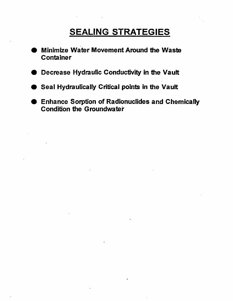
SEALING STRATEGIES
• Minimize Water Movement Around the WasteContainer
• Decrease Hydraulic Conductivity in the Vault
• Seal Hydraulically Critical points in the Vault
• Enhance Sorption of Radionuclides and ChemicallyCondition the Groundwater


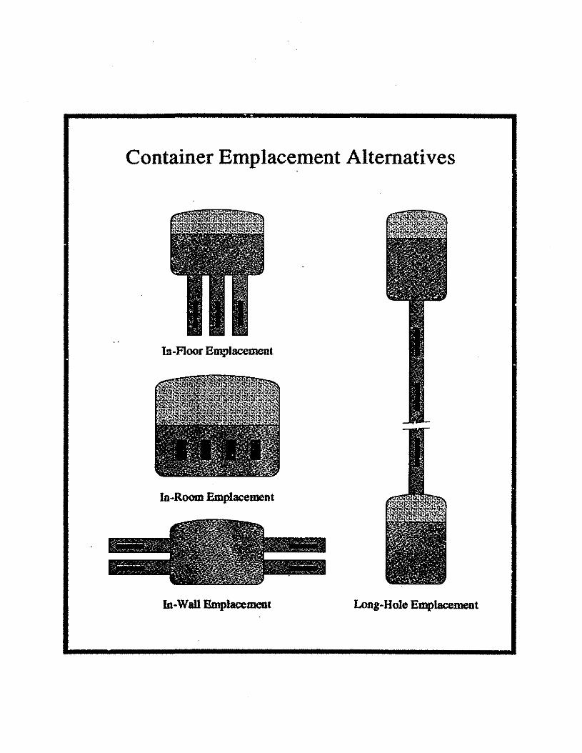
Container Emplacement Alternatives
In-Floor Emplacement
In-Room Emplacement
In-Wall Emplacement Long-Hole Emplacement
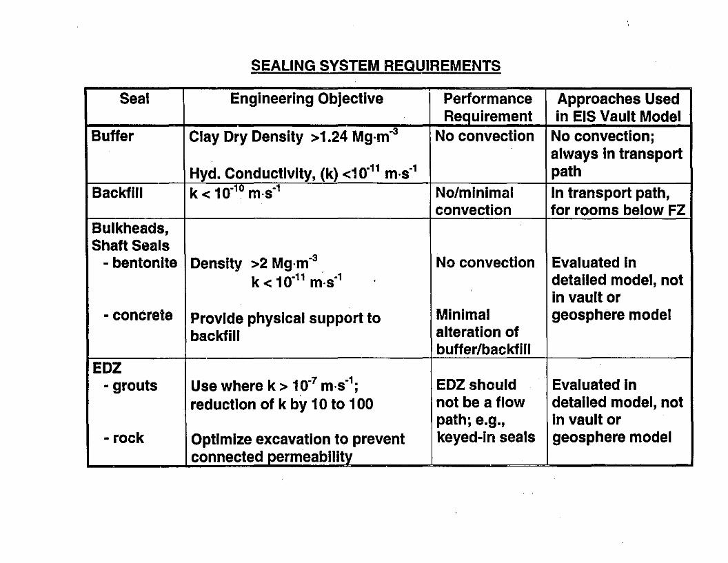
SEALING SYSTEM REQUIREMENTS
Seal Engineering Objective Performance Approaches UsedRequirement in EIS Vault Model
Buffer Clay Dry Density >1.24 Mg·m-3 No convection No convection;always In transport
Hyd. Conductivity, (k) <10-11 m·s-1 pathBackfill k < 10-10 m·s-1 No/minimal In transport path,
convection for rooms below FZBulkheads,Shaft Seals
- bentonite Density >2 Mg·m-3. No convection Evaluated In
k < 10-11 m·s-1 detailed model, not,in vault or
- concrete Provide physical support to Minimal geosphere modelbackfill alteration of
buffer/backfillEDZ
- grouts Use where k > 10-7 m·s-1; EDZ should Evaluated In
reduction of k by 10 to 100 not be a flow detailed model, notpath; e.g., in vault or
- rock Optimize excavation to prevent keyed-In seals geosphere modelconnected oermeabllitv
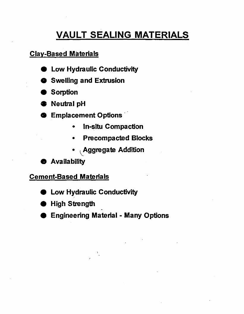
VAULT SEALING MATERIALS
Q!!v-Based Materials
• Low Hydraulic Conductivity
• Swelling and Extrusion
• Sorption
• Neutral pH
• Emplacement Options'
• In-situ Compaction
• Precompacted Blocks
• ,--Aggregate Addition
• Availability
Cement-Based Materials
• Low Hydraulic Conductivity
• High Strength
• Engineering Material - Many Options
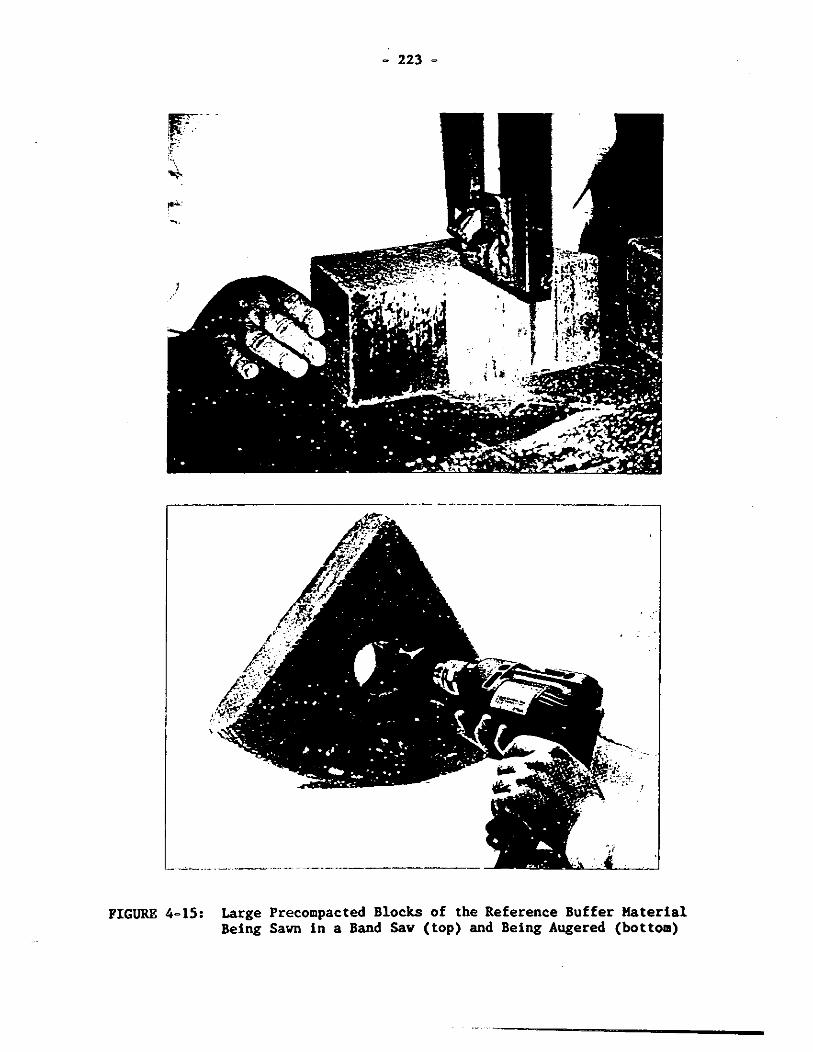
- 223 -
IT-- -!f~.·· ,"r:4-!*'"""
--
,----------------------
-'
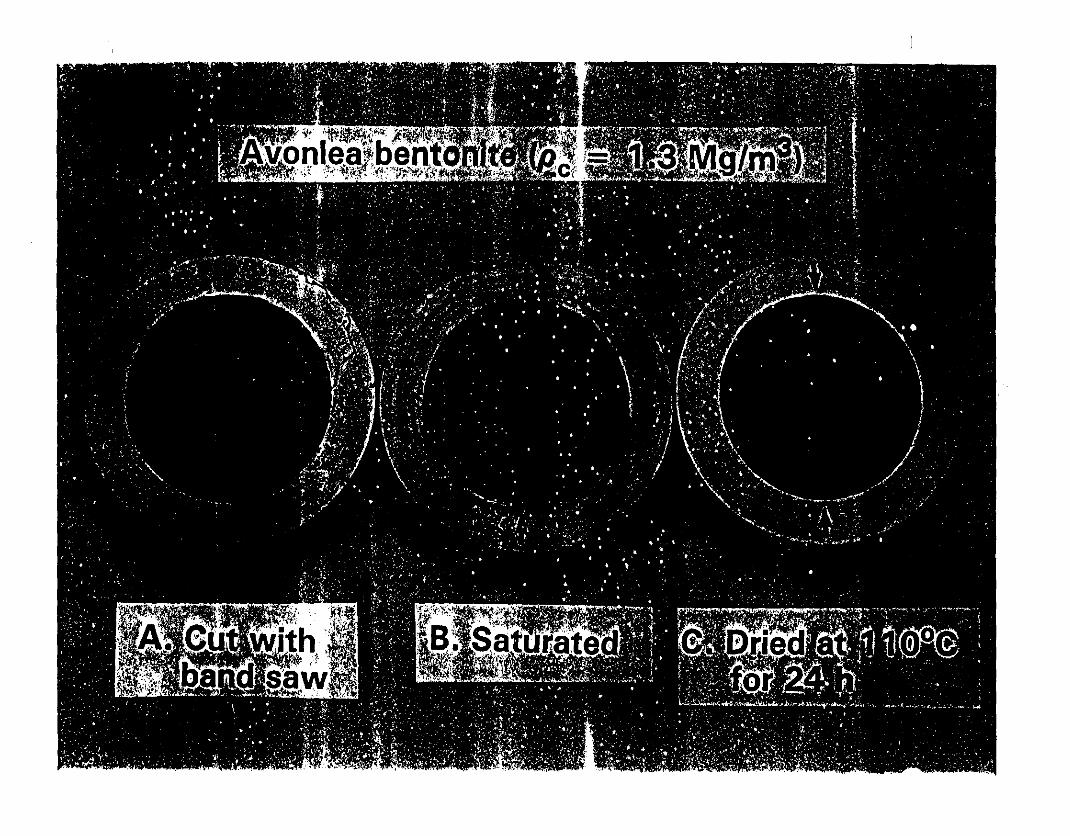
FIGURE 4-15: Large Precompacted Blocks of the Reference Buffer MaterialBeing Sawn in a Band Saw (top) and Being Augered (bottom)
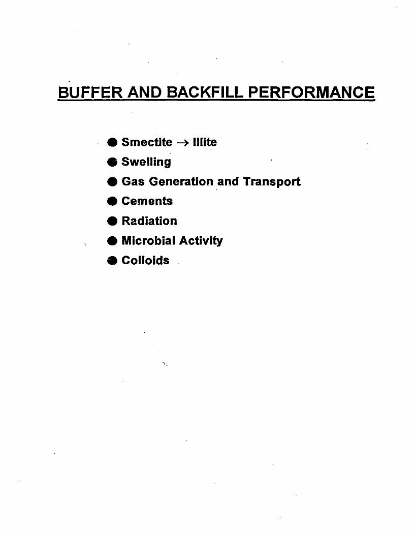
BUFFER AND BACKFILL PERFORMANCE
• Smectite ~ Illite
• Swelling
• Gas Generation and Transport
• Cements
• Radiation
• Microbial Activity
• Colloids
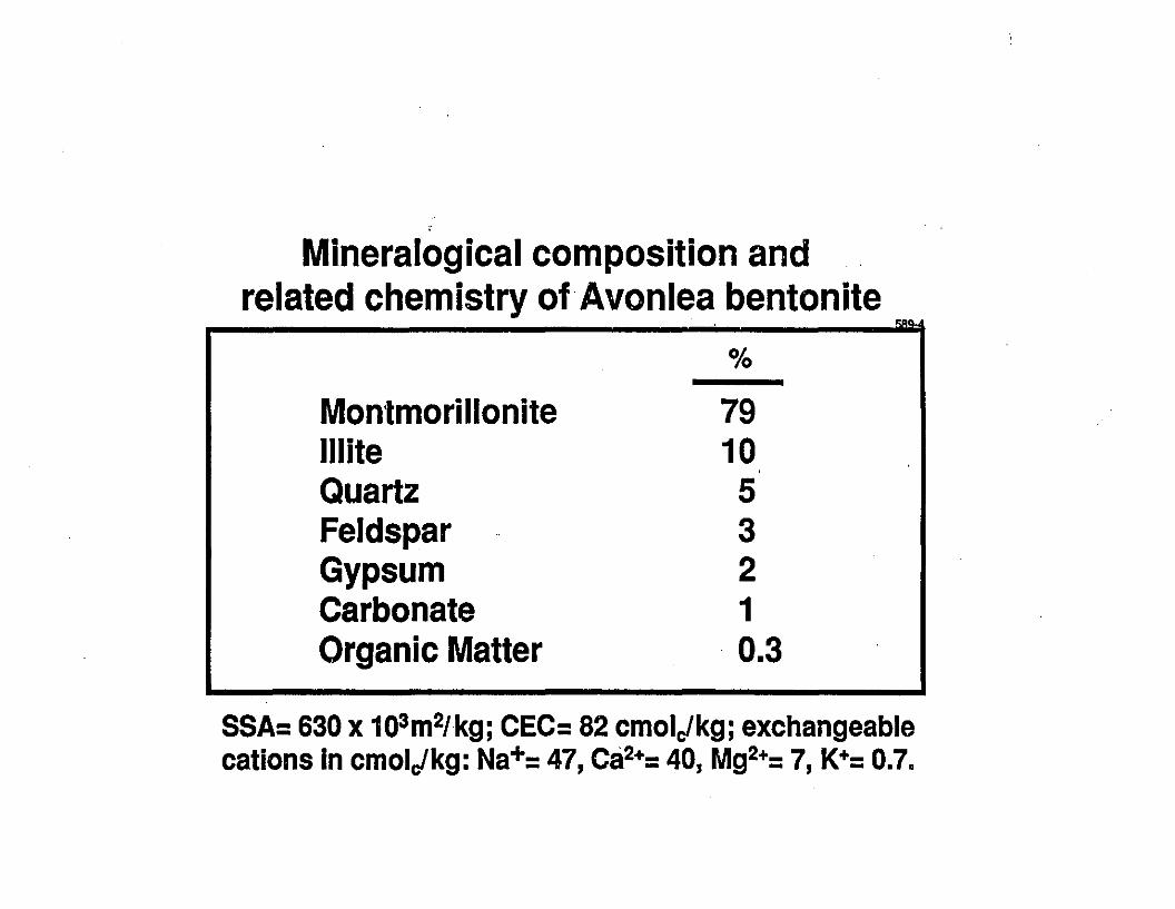
Mineralogical composition andrelated chemistry ofAvonlea bentonite
%
Montmorillonite 79Illite 10Quartz 5Feldspar 3Gypsum 2Carbonate 1Organic Matter 0.3
SSA= 630 x 103m21kg; CEC= 82 cmolJkg; exchangeablecations in cmolJkg: Na+= 47, Ca2+= 40, Mg2+= 7, K+= 0.7.
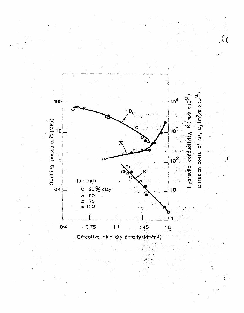
,'.-.•.
"<t"<t
100 104 ""0....0........ xx
f/)
.~ (\I'~ E E<tl ~ ~
Q.\~ f/)
~ 10 103 0
~>: -" ....
';'- (f)- >Q) -.... .....:J ·.,0 0lIJ :JlIJ
~. ,:.-- ;;.".,:, '0 .,.:Q) .c: - J....
102 0 Q)a. 1 . 0 00
Ol 0c: c::J .Q
Q) <tl f/).... :J:5: legend: '0 -C/) >. -0-1 25% clay
:x: 00 10h. 50[J. 750100
0-4 0-75 1045
Effect ive clay dry density (MgAn3)
( ,
.'..., .
.,
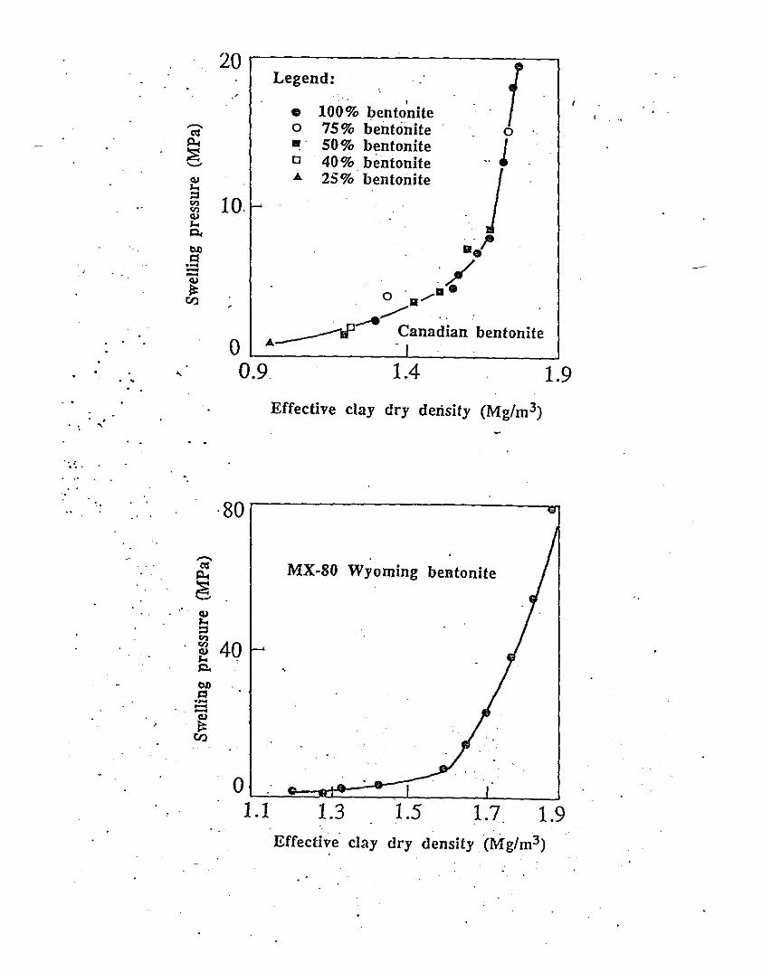
20
fLegend:, , ,
• 100 % I;>entonite---.. 0 75% bentonite 0c<:
50% bentonite IPo< ••~ a 40% bentonite •••'-'
jOJ A 25%· bentonite.....= 10.." I---'"OJ.....~ 11/l>Dl:l ./.....--OJ~ . .8
v.l o .. ""'"---,../"' " .
~ Canadian bentonite0 A • I
.. 0.9 1.4 1.9
Effective clay dry density (Mg/m 3)
·80
---..c<: MX·80 Wyoming bentonitePo<~'-'
.' .OJ.....=."." 40OJ.....~ ,l>Dl:l.---'"~
v.l
01.1 1.3 1.5 1.7 1.9
Effective clay dry density (Mg/m3)
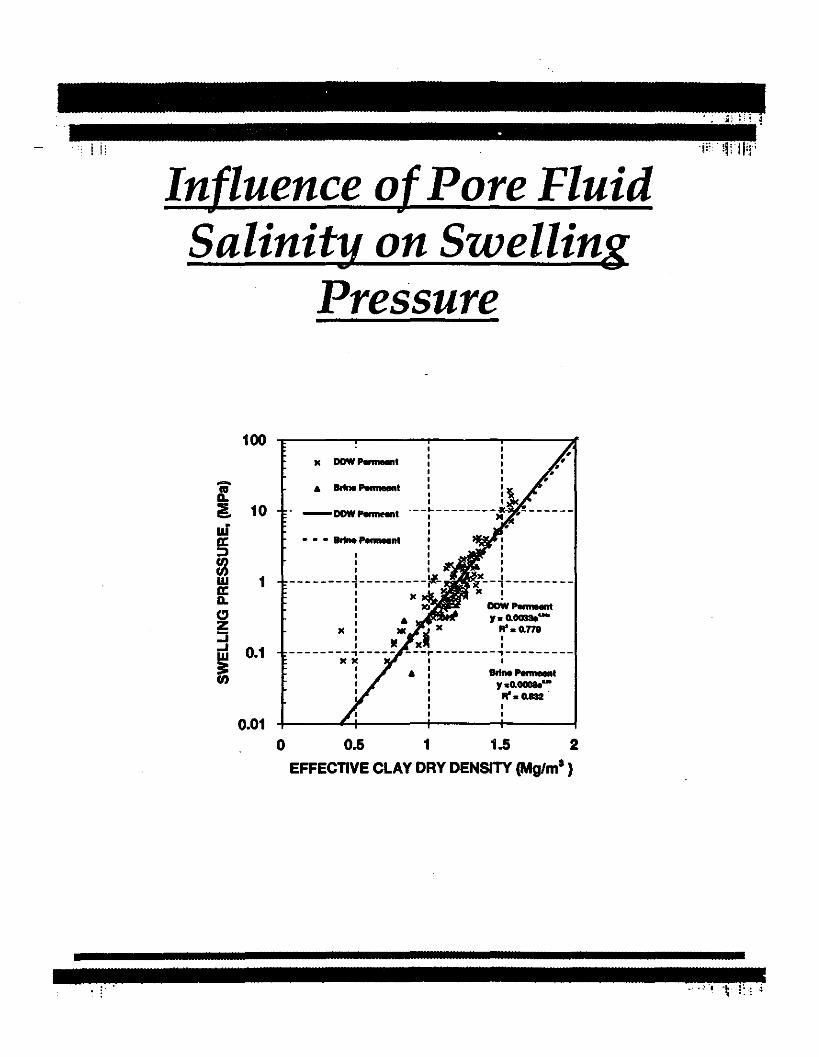
Influence ofPore FluidSalinity on Swelling
Pressure
100
::i§. 10
0.01
I
Ie DOW~t :II
& -- :~I 1
-DOW".,.., ._-~--------:
II
••• BrIne"""'nt IIII
I I
--------~---------~-: xI XI DOW Perrne-.t:. .,. o.OO33e~
J( : ,. 'l x ft.G.778
I If xII :--------,----- ---~--------,---------x X I I
: • : Brtne PMneent: I .,.o.~-
: .... G.882 .I II I
o 0.5 1 1.5 2
EFFECTIVE CLAY DRY DENSITY (Mg/ml)
. :
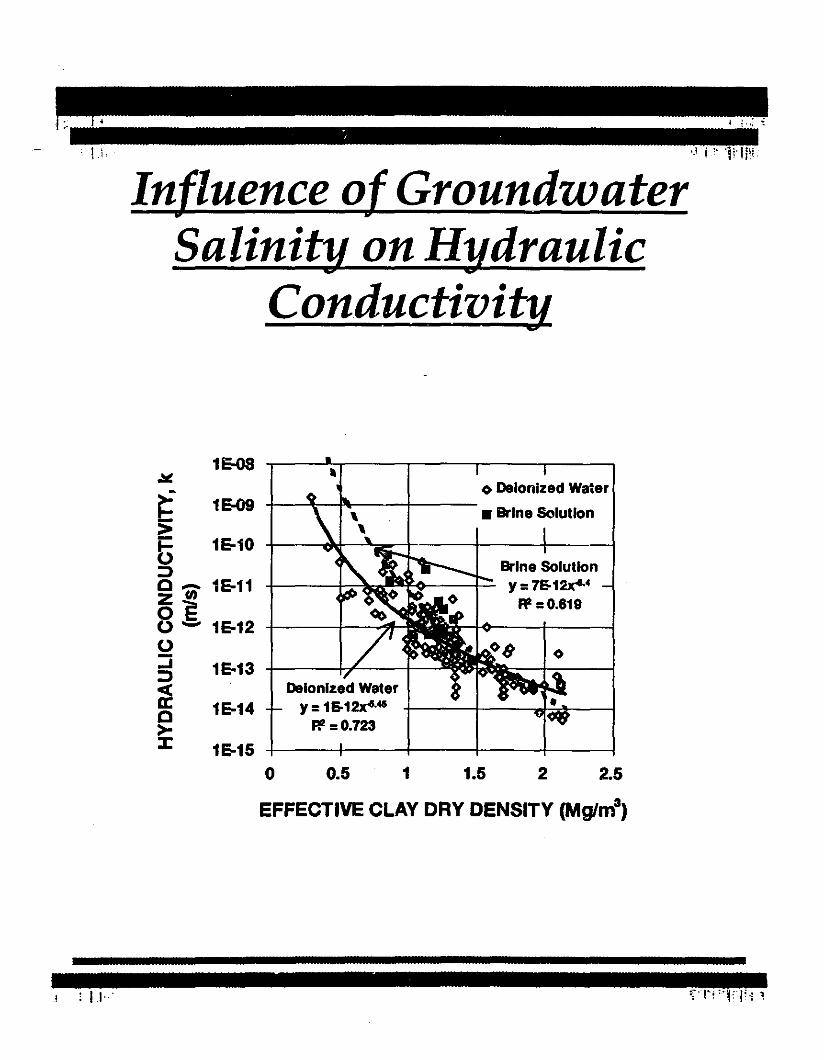
Influence of GroundwaterSalinity on Hydraulic
Conductivity-
1~ ~-..L.,---~-~--~-~II
2.521.50.5 1
Deionized Wlltery =1&12lr'-45
p,z =0.723
1&15 -1---+--+-------t---l-------j
o
1&14
<> Deionized Wa~erg 1E-09 -!-.....:{--Plo--\--+---. Brine Solution
f3 1&10:;) Brine SolutionC 0' 1&11 -I----J.~~il¥<l~_____l.::::. y =7&12lr'-4
~ E "=0.819o - 1&12 -1---+--4o:::i 1&13 -l-----++---+--:;)
~C>:I:
EFFECTIVE CLAY DRY DENSITY (Mglm3)
I ; II'"
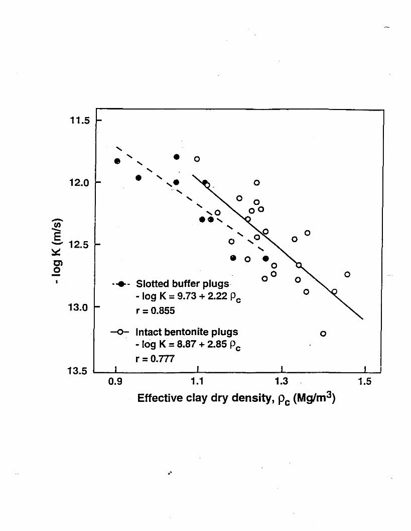
11.5
, , • 0• .... ,12.0 • .... ..... 0., , 0,
,0- .. ,en ,- , 0 0E o ,0 0- 12.5~
,en e 0 •00
00 0- 0• -+- Slotted buffer plugs- log K =9.73 + 2.22 Pc 0
13.0 r =0.855
-0- Intact bentonite plugs 0-log K =8.87 + 2.85 Pcr =0.777
13.50.9 1.1 1.3 1.5
Effective clay dry density, Pc (Mg/m3)
.'

Gas BreakthroughResistance in Bentonite
lechanisms that may createathways through porous media
- Diffusion
- Capillarity
- Pathway Dilatancy
- Tensile Fracturing
)ossible gas pressure conditions
- gas pressure < pore water (PWP)
- gas pressure >PWP but < total soilpressure
- gas pressure> total soil pressure
II '

GAS FLOW MECHANISMS, -
DIFFUSIONDISSOLUTION OF GASES IN
THE WATER PHASE
2-PHASE FLOW
WATER IS PUSHED THROUGH
SOME PORES BY INVADING GAS
PORE DILATIONDEFORMATION OF SOIL FABRIC
CREATING LARGER PORES TO
ACCOMODATE GAS FLOW
FISSURING
CREATION OF NEW PORES
TO ACCOMODATE GAS FLOW

BUFFER GAS-BREAKTHROUGH
TEST RESULTS
10 ,-----,------,----.-----,------.
2.52.0
Gas-breakthrough
= 9.4 MPa
1.5
Gas inflow.... ~~. "
Gas
collection
1.00.5
Test BT3 (buffer)
8 Pdry ~ 1.67 Mg/m3
w = 11.2%
8=49%
2
oM::::===:::r:::::::===:::c:::===r:::==~-~0.0
Elapsed time (hours)

Diffusion in Buffer and Backfill
k < 10.10 mts - diffusion dominant
0, Total Intrinsic Diffusion Coefficient from
J = -0 (8 c t 8 x); 0 = Do't&
Da , Apparent Diffusion Coefficient from
r = Capacity Factor (& + p~)
o and r from - Laboratory Experiments
- Literature
- Expert Judgement
r
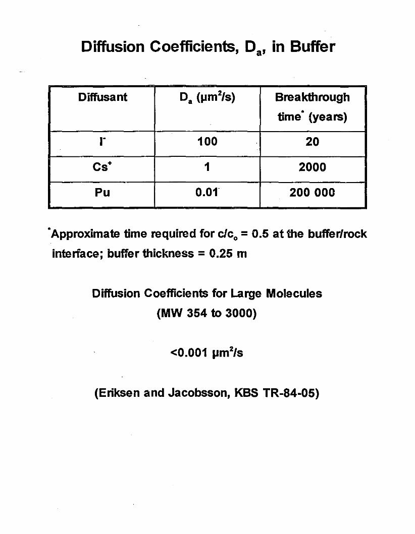
Diffusion Coefficients, Da, in Buffer
Diffusant Da (JJm2/s) Breakthrough
time· (years)
r 100 20
Cs+ 1 2000
Pu O.Of 200000
•Approximate time required for clco = 0.5 at the buffer/rock
interface; buffer thickness = 0.25 m
Diffusion Coefficients for Large Molecules
(MW 354 to 3000)
(Eriksen and Jacobsson, KBS TR-84-05)

Total intrinsic diffusion coefficients, OJ' for r inintact and defected bentonite plugs
110
.90
-~N 70E.;!,G):2 50't:JoC
C 30
10
o Intact plugs• slotted plugs
Io BCXplugs
~ -
--0
c-
Ol range specifIedIn vault model- for buffer andbackfill'
l-
•- 0
0 0
• 041 §
r- --
I I I I I
0.9 1.0 1.1 1.2 1.3 1.5
Effective clay dry density (Mglm3)
AK-58-01

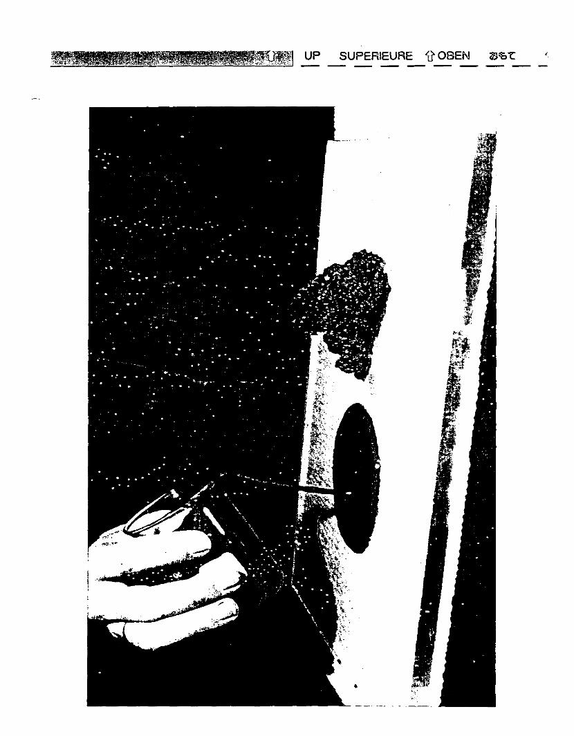
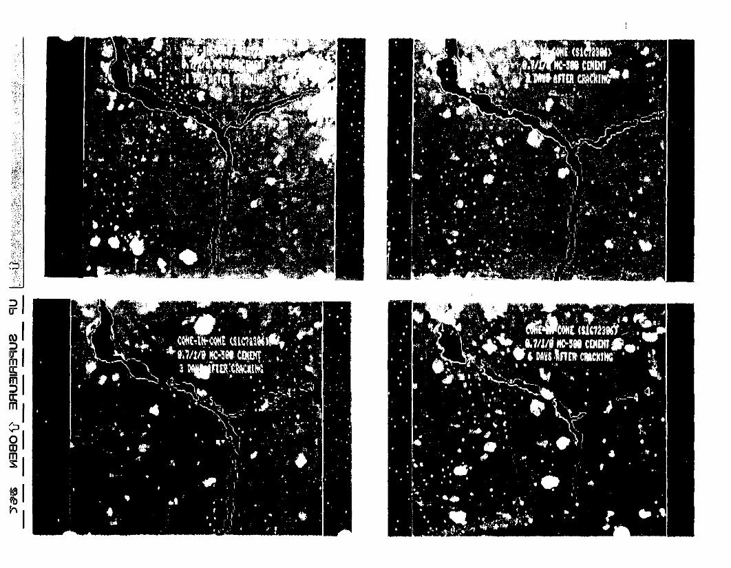
Cement-based Materials
- For high-level waste disposal, generallyrestricted to grouting, shaft seal andconstruction applications (e.g., bulkheads,floors)
- Low pH concretes have been developed thatare more compatible with clay buffers andbackfills
page 8
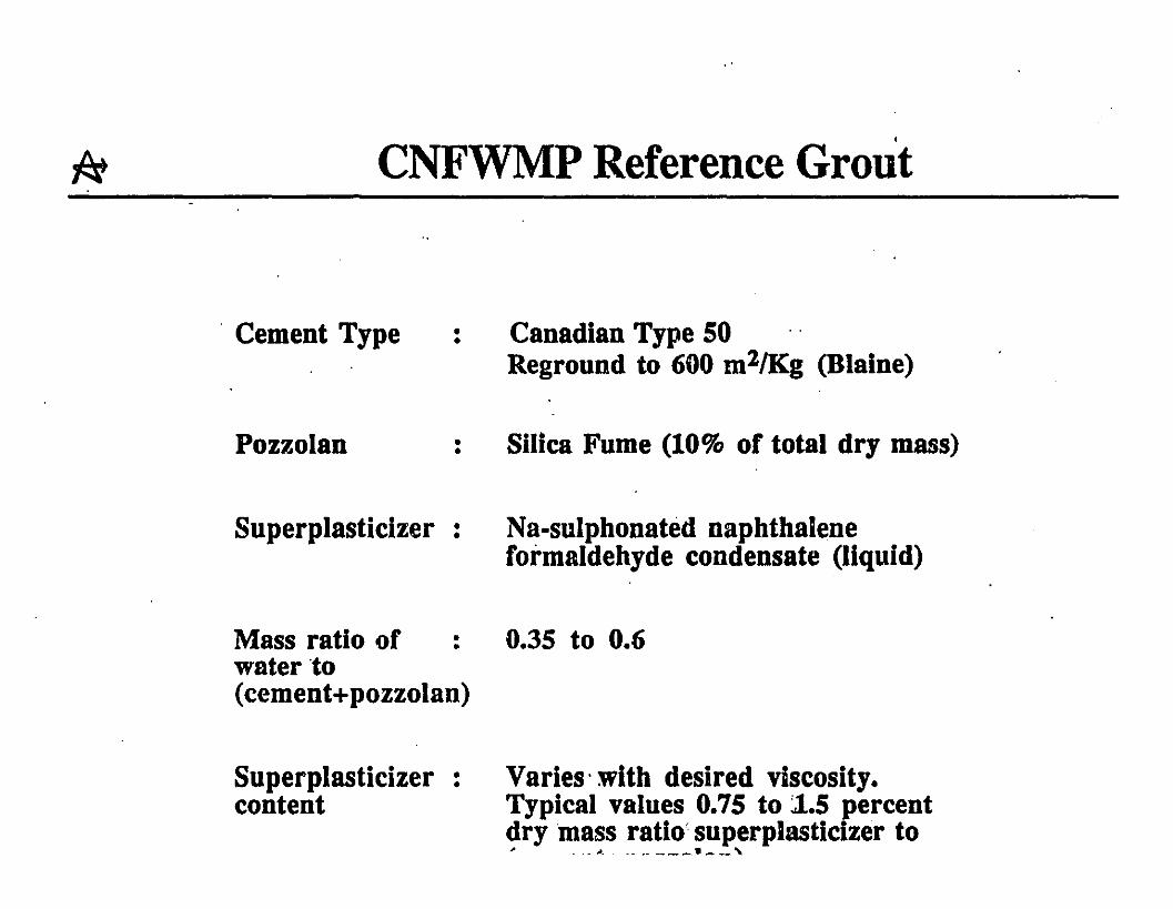
CNFWMP Reference Grout
. Cement Type
Pozzolan
••
••
Canadian Type 50Reground to 600 m2/Kg (Blaine)
Silica Fume (10% of total dry mass)
Superplasticizer :
Mass ratio of :water ·to(cement+pozzolan)
Superplasticizer :content
Na-sulphonated naphthaleneformaldehyde condensate (liquid)
0.35 to 0.6
Varies' with desired viscosity.Typical values 0.75 to ~.5 percentdry mass ratio'superplasticizer to~ . -~. -- .. ---_ ........._,
UP SUPEFlIEURE "d' OSEN ~'OL,

1.61.20.4 0.8
w/cm
EFFECT OF WATE~/CEMENTITIOUS MATERIALRATIOS ON THE HYDRAUUC CONDUCTIVITY
OF GROUTS
10-16 L..-.L--'-_...J.......-'-'''--'---L-__''"'''--.a--l__a_ -o.-I
0.0
- 10-9...I
ID
S 10-10-~e 10-11
&-!t.)
bQ 10-12Z0r.,)
U 10-13::s~= 10-14,
~10-15

I./
/"/
//
I.-"
- BEFORETEST- - AFTER TEST
0.40-...IbO 0.35.!:Ill
II')
80.30-
~0.25:3
0> 0.20rz:IP::0
0.15Clt
~ 0.10
; 0.050u 0.00
1000 100 10 1 0.1 0.01 0.001
PORE DIAMETER ( p;m )
CHANGE IN PORE-SIZE DISTRIBUTION OF CEMENT-BASEDGROUT (W/CJl=O.4, TWO PARTICLE SIZES: t = 1.~~ mm AND
t = 0.30 mm) COMPACTED AT p = 1.6 Mg m .

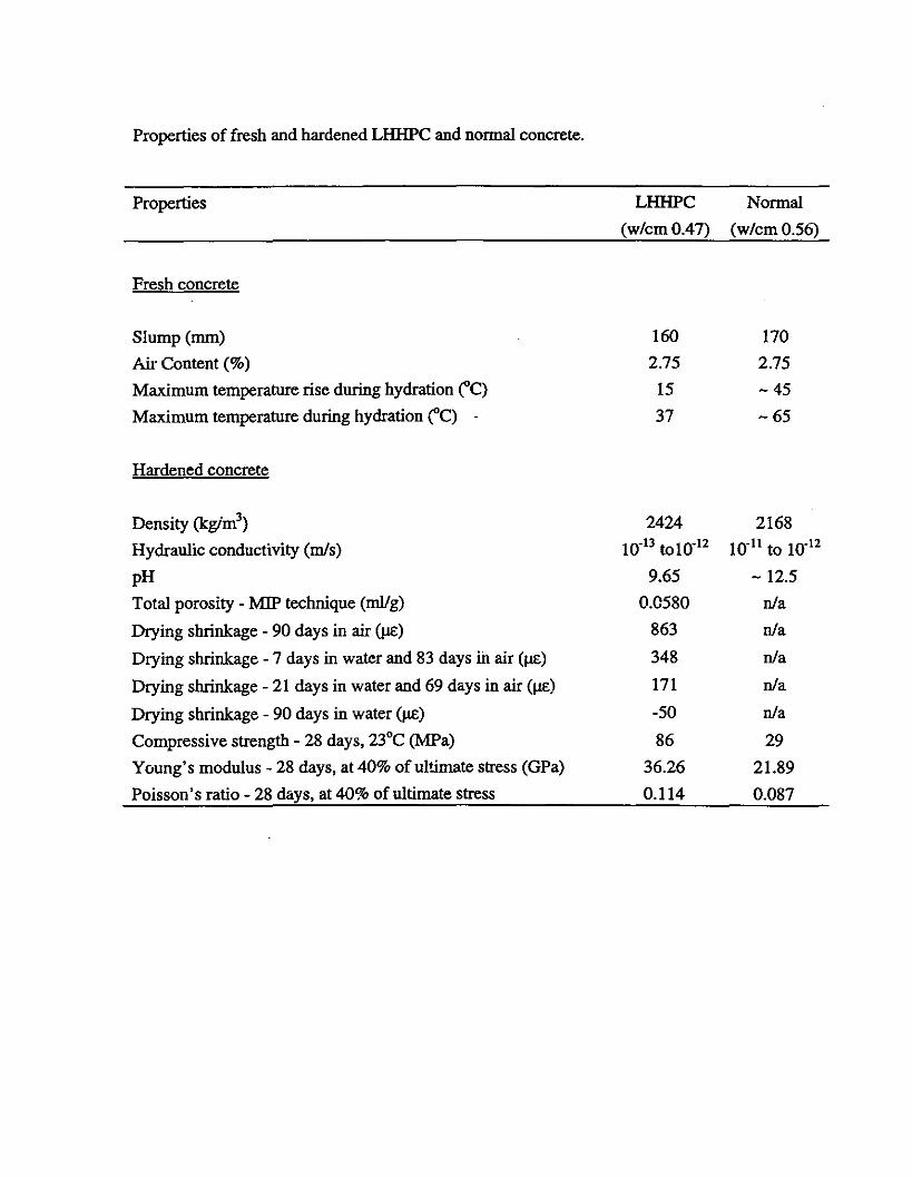
Properties of fresh and hardened LHHPC and nonna! concrete.
Properties LHHPC Nonna!
(w/cmO.47) (w/cmO.56)
Fresh concrete
Slump(mm) 160 170
Air Content (%) 2.75 2.75
Maximum temperature rise during hydration ("C) 15 -45
Maximum temperature during hydration ("C) 37 -65
Hardened concrete
Density (kgim3) 2424 2168
Hydraulic conductivity (m1s) 10-13 to10-12 10-11 to 10-12
pH 9.65 -12.5
Total porosity - MIP technique (mlIg) 0.0580 nla
Drying shrinkage - 90 days in air (J.I£) 863 nla
Drying shrinkage - 7 days in water and 83 days in air (J.I£) 348 nla
Drying shrinkage - 21 days in water and 69 days in air (J.I£) 171 nla
Drying shrinkage - 90 days in water (J.I£) -50 nla
Compressive strength - 28 days, 23°C (MPa) 86 29
Young's modulus - 28 days, at 40% of ultimate stress (GPa) 36.26 21.89
Poisson's ratio - 28 days, at 40% of ultimate stress 0.114 0.087