Seagate® Nytro™ XP3000 Flash Series Accelerator Cards ... · Seagate IronWolf 110 SSD Product...
30
Seagate® IronWolf™ 110 SSD Product Manual 100841919, Rev B August 2019, ZA240NM10001 ZA480NM10001 ZA960NM10001 ZA1920NM10001 ZA3840NM10001
Transcript of Seagate® Nytro™ XP3000 Flash Series Accelerator Cards ... · Seagate IronWolf 110 SSD Product...
Seagate® IronWolf™ 110 SSD
Product Manual
100841919, Rev BAugust 2019,
ZA240NM10001ZA480NM10001ZA960NM10001ZA1920NM10001ZA3840NM10001
© 2019, Seagate Technology LLC All rights reserved. Publication number: 100847099, Rev. B , August 2019 .
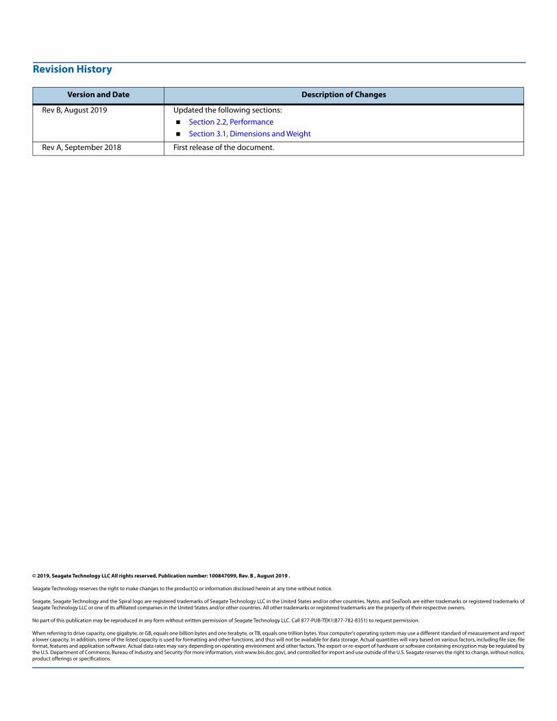
Revision History
Version and Date Description of Changes
Rev B, August 2019 Updated the following sections: Section 2.2, Performance Section 3.1, Dimensions and Weight
Rev A, September 2018 First release of the document.
Seagate Technology reserves the right to make changes to the product(s) or information disclosed herein at any time without notice.
Seagate, Seagate Technology and the Spiral logo are registered trademarks of Seagate Technology LLC in the United States and/or other countries. Nytro, and SeaTools are either trademarks or registered trademarks ofSeagate Technology LLC or one of its affiliated companies in the United States and/or other countries. All other trademarks or registered trademarks are the property of their respective owners.
No part of this publication may be reproduced in any form without written permission of Seagate Technology LLC. Call 877-PUB-TEK1(877-782-8351) to request permission.
When referring to drive capacity, one gigabyte, or GB, equals one billion bytes and one terabyte, or TB, equals one trillion bytes. Your computer’s operating system may use a different standard of measurement and reporta lower capacity. In addition, some of the listed capacity is used for formatting and other functions, and thus will not be available for data storage. Actual quantities will vary based on various factors, including file size, fileformat, features and application software. Actual data rates may vary depending on operating environment and other factors. The export or re-export of hardware or software containing encryption may be regulated bythe U.S. Department of Commerce, Bureau of Industry and Security (for more information, visit www.bis.doc.gov), and controlled for import and use outside of the U.S. Seagate reserves the right to change, without notice,product offerings or specifications.
Seagate IronWolf 110 SSD Product Manual, Rev B 3
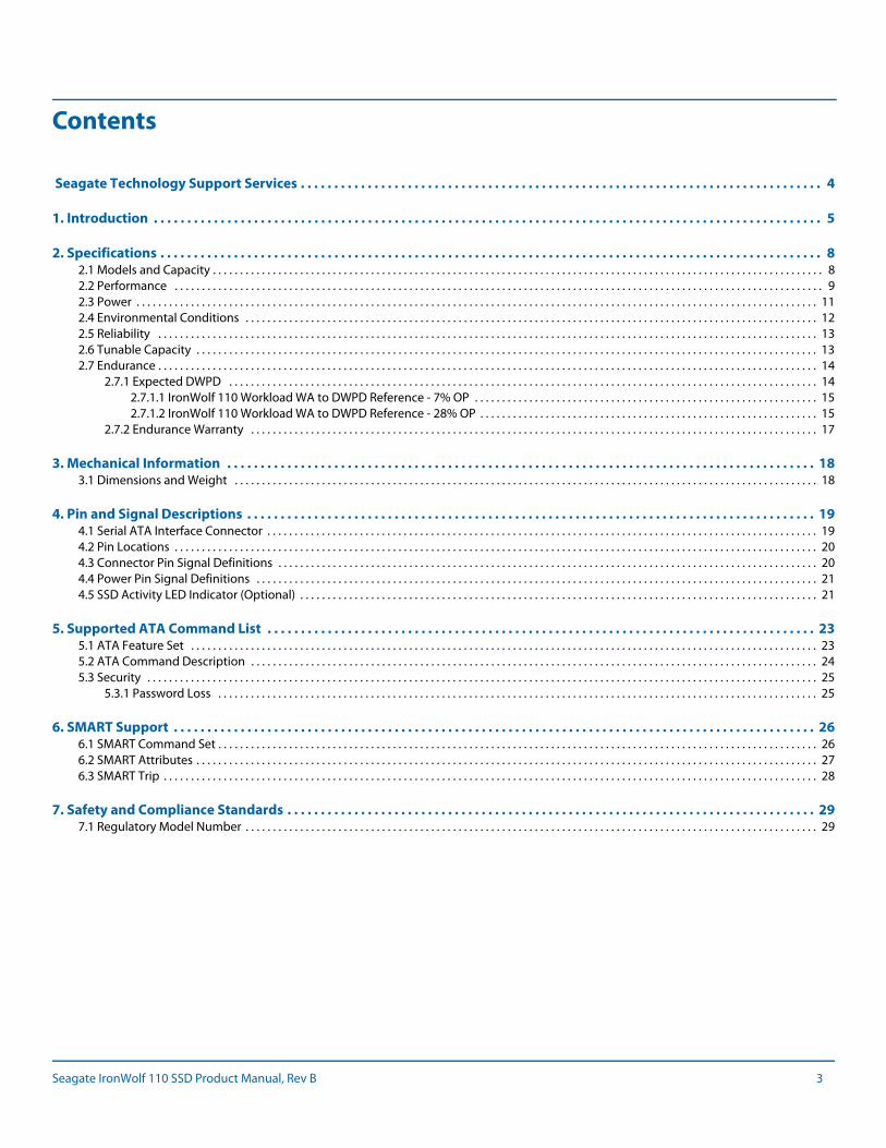
Contents
Seagate Technology Support Services . . . . . . . . . . . . . . . . . . . . . . . . . . . . . . . . . . . . . . . . . . . . . . . . . . . . . . . . . . . . . . . . . . . . . . . . . . . . . . 4
1. Introduction . . . . . . . . . . . . . . . . . . . . . . . . . . . . . . . . . . . . . . . . . . . . . . . . . . . . . . . . . . . . . . . . . . . . . . . . . . . . . . . . . . . . . . . . . . . . . . . . . . . . 5
2. Specifications . . . . . . . . . . . . . . . . . . . . . . . . . . . . . . . . . . . . . . . . . . . . . . . . . . . . . . . . . . . . . . . . . . . . . . . . . . . . . . . . . . . . . . . . . . . . . . . . . . . 82.1 Models and Capacity . . . . . . . . . . . . . . . . . . . . . . . . . . . . . . . . . . . . . . . . . . . . . . . . . . . . . . . . . . . . . . . . . . . . . . . . . . . . . . . . . . . . . . . . . . . . . . . . . . . . . . . . . . . . . . . . 82.2 Performance . . . . . . . . . . . . . . . . . . . . . . . . . . . . . . . . . . . . . . . . . . . . . . . . . . . . . . . . . . . . . . . . . . . . . . . . . . . . . . . . . . . . . . . . . . . . . . . . . . . . . . . . . . . . . . . . . . . . . . . 92.3 Power . . . . . . . . . . . . . . . . . . . . . . . . . . . . . . . . . . . . . . . . . . . . . . . . . . . . . . . . . . . . . . . . . . . . . . . . . . . . . . . . . . . . . . . . . . . . . . . . . . . . . . . . . . . . . . . . . . . . . . . . . . . . . 112.4 Environmental Conditions . . . . . . . . . . . . . . . . . . . . . . . . . . . . . . . . . . . . . . . . . . . . . . . . . . . . . . . . . . . . . . . . . . . . . . . . . . . . . . . . . . . . . . . . . . . . . . . . . . . . . . . . . 122.5 Reliability . . . . . . . . . . . . . . . . . . . . . . . . . . . . . . . . . . . . . . . . . . . . . . . . . . . . . . . . . . . . . . . . . . . . . . . . . . . . . . . . . . . . . . . . . . . . . . . . . . . . . . . . . . . . . . . . . . . . . . . . . 132.6 Tunable Capacity . . . . . . . . . . . . . . . . . . . . . . . . . . . . . . . . . . . . . . . . . . . . . . . . . . . . . . . . . . . . . . . . . . . . . . . . . . . . . . . . . . . . . . . . . . . . . . . . . . . . . . . . . . . . . . . . . . 132.7 Endurance . . . . . . . . . . . . . . . . . . . . . . . . . . . . . . . . . . . . . . . . . . . . . . . . . . . . . . . . . . . . . . . . . . . . . . . . . . . . . . . . . . . . . . . . . . . . . . . . . . . . . . . . . . . . . . . . . . . . . . . . . 14
2.7.1 Expected DWPD . . . . . . . . . . . . . . . . . . . . . . . . . . . . . . . . . . . . . . . . . . . . . . . . . . . . . . . . . . . . . . . . . . . . . . . . . . . . . . . . . . . . . . . . . . . . . . . . . . . . . . . . . . . . 142.7.1.1 IronWolf 110 Workload WA to DWPD Reference - 7% OP . . . . . . . . . . . . . . . . . . . . . . . . . . . . . . . . . . . . . . . . . . . . . . . . . . . . . . . . . . . . . . . 152.7.1.2 IronWolf 110 Workload WA to DWPD Reference - 28% OP . . . . . . . . . . . . . . . . . . . . . . . . . . . . . . . . . . . . . . . . . . . . . . . . . . . . . . . . . . . . . . 15
2.7.2 Endurance Warranty . . . . . . . . . . . . . . . . . . . . . . . . . . . . . . . . . . . . . . . . . . . . . . . . . . . . . . . . . . . . . . . . . . . . . . . . . . . . . . . . . . . . . . . . . . . . . . . . . . . . . . . . 17
3. Mechanical Information . . . . . . . . . . . . . . . . . . . . . . . . . . . . . . . . . . . . . . . . . . . . . . . . . . . . . . . . . . . . . . . . . . . . . . . . . . . . . . . . . . . . . . . . 183.1 Dimensions and Weight . . . . . . . . . . . . . . . . . . . . . . . . . . . . . . . . . . . . . . . . . . . . . . . . . . . . . . . . . . . . . . . . . . . . . . . . . . . . . . . . . . . . . . . . . . . . . . . . . . . . . . . . . . . 18
4. Pin and Signal Descriptions . . . . . . . . . . . . . . . . . . . . . . . . . . . . . . . . . . . . . . . . . . . . . . . . . . . . . . . . . . . . . . . . . . . . . . . . . . . . . . . . . . . . . 194.1 Serial ATA Interface Connector . . . . . . . . . . . . . . . . . . . . . . . . . . . . . . . . . . . . . . . . . . . . . . . . . . . . . . . . . . . . . . . . . . . . . . . . . . . . . . . . . . . . . . . . . . . . . . . . . . . . . 194.2 Pin Locations . . . . . . . . . . . . . . . . . . . . . . . . . . . . . . . . . . . . . . . . . . . . . . . . . . . . . . . . . . . . . . . . . . . . . . . . . . . . . . . . . . . . . . . . . . . . . . . . . . . . . . . . . . . . . . . . . . . . . . 204.3 Connector Pin Signal Definitions . . . . . . . . . . . . . . . . . . . . . . . . . . . . . . . . . . . . . . . . . . . . . . . . . . . . . . . . . . . . . . . . . . . . . . . . . . . . . . . . . . . . . . . . . . . . . . . . . . . 204.4 Power Pin Signal Definitions . . . . . . . . . . . . . . . . . . . . . . . . . . . . . . . . . . . . . . . . . . . . . . . . . . . . . . . . . . . . . . . . . . . . . . . . . . . . . . . . . . . . . . . . . . . . . . . . . . . . . . . 214.5 SSD Activity LED Indicator (Optional) . . . . . . . . . . . . . . . . . . . . . . . . . . . . . . . . . . . . . . . . . . . . . . . . . . . . . . . . . . . . . . . . . . . . . . . . . . . . . . . . . . . . . . . . . . . . . . . 21
5. Supported ATA Command List . . . . . . . . . . . . . . . . . . . . . . . . . . . . . . . . . . . . . . . . . . . . . . . . . . . . . . . . . . . . . . . . . . . . . . . . . . . . . . . . . . 235.1 ATA Feature Set . . . . . . . . . . . . . . . . . . . . . . . . . . . . . . . . . . . . . . . . . . . . . . . . . . . . . . . . . . . . . . . . . . . . . . . . . . . . . . . . . . . . . . . . . . . . . . . . . . . . . . . . . . . . . . . . . . . 235.2 ATA Command Description . . . . . . . . . . . . . . . . . . . . . . . . . . . . . . . . . . . . . . . . . . . . . . . . . . . . . . . . . . . . . . . . . . . . . . . . . . . . . . . . . . . . . . . . . . . . . . . . . . . . . . . . 245.3 Security . . . . . . . . . . . . . . . . . . . . . . . . . . . . . . . . . . . . . . . . . . . . . . . . . . . . . . . . . . . . . . . . . . . . . . . . . . . . . . . . . . . . . . . . . . . . . . . . . . . . . . . . . . . . . . . . . . . . . . . . . . . 25
5.3.1 Password Loss . . . . . . . . . . . . . . . . . . . . . . . . . . . . . . . . . . . . . . . . . . . . . . . . . . . . . . . . . . . . . . . . . . . . . . . . . . . . . . . . . . . . . . . . . . . . . . . . . . . . . . . . . . . . . . 25
6. SMART Support . . . . . . . . . . . . . . . . . . . . . . . . . . . . . . . . . . . . . . . . . . . . . . . . . . . . . . . . . . . . . . . . . . . . . . . . . . . . . . . . . . . . . . . . . . . . . . . . 266.1 SMART Command Set . . . . . . . . . . . . . . . . . . . . . . . . . . . . . . . . . . . . . . . . . . . . . . . . . . . . . . . . . . . . . . . . . . . . . . . . . . . . . . . . . . . . . . . . . . . . . . . . . . . . . . . . . . . . . . 266.2 SMART Attributes . . . . . . . . . . . . . . . . . . . . . . . . . . . . . . . . . . . . . . . . . . . . . . . . . . . . . . . . . . . . . . . . . . . . . . . . . . . . . . . . . . . . . . . . . . . . . . . . . . . . . . . . . . . . . . . . . . 276.3 SMART Trip . . . . . . . . . . . . . . . . . . . . . . . . . . . . . . . . . . . . . . . . . . . . . . . . . . . . . . . . . . . . . . . . . . . . . . . . . . . . . . . . . . . . . . . . . . . . . . . . . . . . . . . . . . . . . . . . . . . . . . . . 28
7. Safety and Compliance Standards . . . . . . . . . . . . . . . . . . . . . . . . . . . . . . . . . . . . . . . . . . . . . . . . . . . . . . . . . . . . . . . . . . . . . . . . . . . . . . . 297.1 Regulatory Model Number . . . . . . . . . . . . . . . . . . . . . . . . . . . . . . . . . . . . . . . . . . . . . . . . . . . . . . . . . . . . . . . . . . . . . . . . . . . . . . . . . . . . . . . . . . . . . . . . . . . . . . . . . 29
Seagate IronWolf 110 SSD Product Manual, Rev B 4
Seagate Technology Support Services
For Internal SSD Support, visit: https://www.seagate.com/support/products/
For Firmware Download and Tools Download for Secure Erase, visit: https://www.seagate.com/support/downloads/
For information regarding online support and services, visit: http://www.seagate.com/contacts/
For information regarding Warranty Support, visit: http://www.seagate.com/support/warranty-and-replacements/
For information regarding data recovery services, visit: http://www.seagate.com/services-software/seagate-recovery-services/recover/
For Seagate OEM and Distribution partner and Seagate reseller portal, visit: http://www.seagate.com/partners
www.Seagate.com
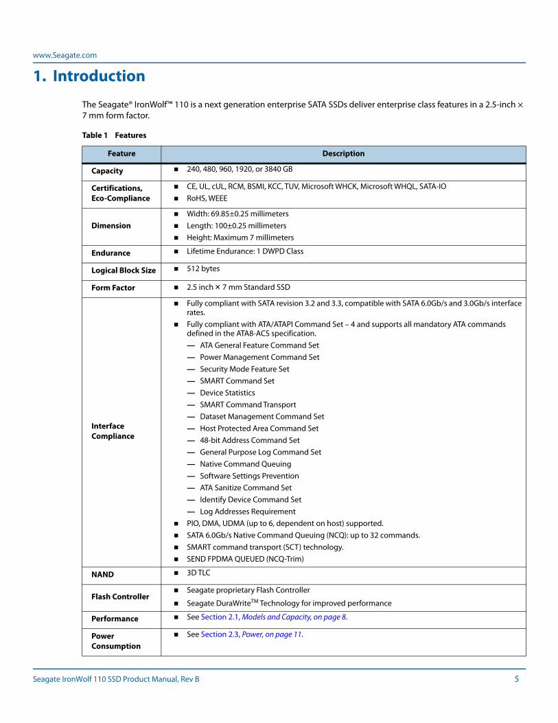
1. Introduction
The Seagate® IronWolf™ 110 is a next generation enterprise SATA SSDs deliver enterprise class features in a 2.5-inch × 7 mm form factor.
Table 1 Features
Feature Description
Capacity 240, 480, 960, 1920, or 3840 GB
Certifications, Eco-Compliance
CE, UL, cUL, RCM, BSMI, KCC, TUV, Microsoft WHCK, Microsoft WHQL, SATA-IO RoHS, WEEE
Dimension Width: 69.85±0.25 millimeters Length: 100±0.25 millimeters Height: Maximum 7 millimeters
Endurance Lifetime Endurance: 1 DWPD Class
Logical Block Size 512 bytes
Form Factor 2.5 inch × 7 mm Standard SSD
Interface Compliance
Fully compliant with SATA revision 3.2 and 3.3, compatible with SATA 6.0Gb/s and 3.0Gb/s interface rates.
Fully compliant with ATA/ATAPI Command Set – 4 and supports all mandatory ATA commands defined in the ATA8-ACS specification.— ATA General Feature Command Set— Power Management Command Set— Security Mode Feature Set — SMART Command Set— Device Statistics— SMART Command Transport— Dataset Management Command Set— Host Protected Area Command Set— 48-bit Address Command Set— General Purpose Log Command Set— Native Command Queuing— Software Settings Prevention— ATA Sanitize Command Set— Identify Device Command Set— Log Addresses Requirement
PIO, DMA, UDMA (up to 6, dependent on host) supported. SATA 6.0Gb/s Native Command Queuing (NCQ): up to 32 commands. SMART command transport (SCT) technology. SEND FPDMA QUEUED (NCQ-Trim)
NAND 3D TLC
Flash Controller Seagate proprietary Flash Controller
Seagate DuraWriteTM Technology for improved performance
Performance See Section 2.1, Models and Capacity, on page 8.
Power Consumption
See Section 2.3, Power, on page 11.
Seagate IronWolf 110 SSD Product Manual, Rev B 5
www.Seagate.com
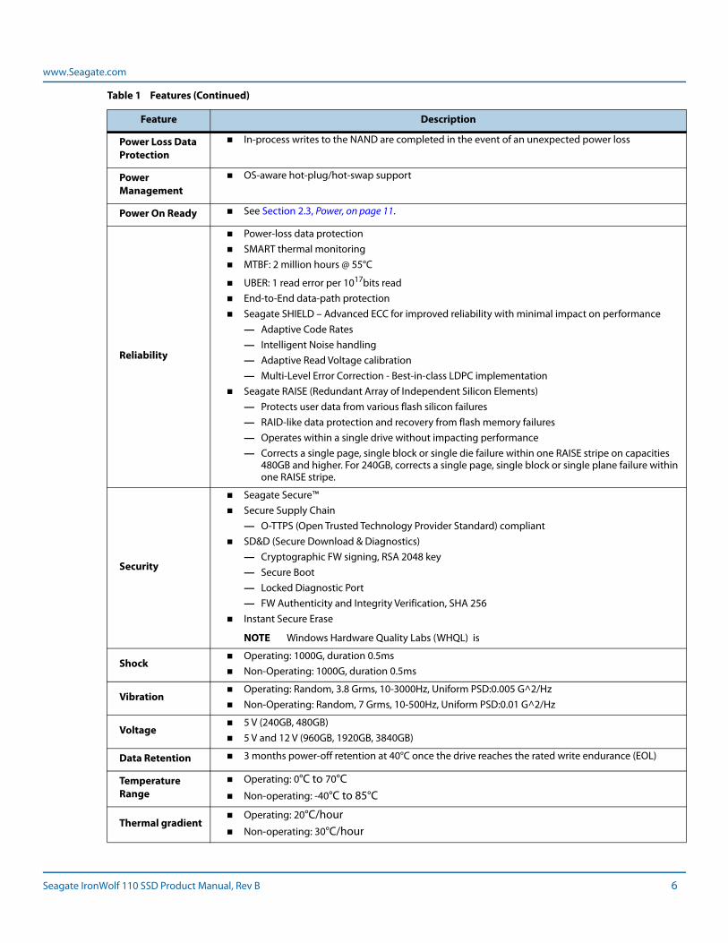
Power Loss Data Protection
In-process writes to the NAND are completed in the event of an unexpected power loss
Power Management
OS-aware hot-plug/hot-swap support
Power On Ready See Section 2.3, Power, on page 11.
Reliability
Power-loss data protection SMART thermal monitoring MTBF: 2 million hours @ 55°C
UBER: 1 read error per 1017bits read End-to-End data-path protection Seagate SHIELD – Advanced ECC for improved reliability with minimal impact on performance
— Adaptive Code Rates— Intelligent Noise handling— Adaptive Read Voltage calibration— Multi-Level Error Correction - Best-in-class LDPC implementation
Seagate RAISE (Redundant Array of Independent Silicon Elements)— Protects user data from various flash silicon failures— RAID-like data protection and recovery from flash memory failures— Operates within a single drive without impacting performance— Corrects a single page, single block or single die failure within one RAISE stripe on capacities
480GB and higher. For 240GB, corrects a single page, single block or single plane failure within one RAISE stripe.
Security
Seagate Secure™ Secure Supply Chain
— O-TTPS (Open Trusted Technology Provider Standard) compliant SD&D (Secure Download & Diagnostics)
— Cryptographic FW signing, RSA 2048 key— Secure Boot— Locked Diagnostic Port— FW Authenticity and Integrity Verification, SHA 256
Instant Secure Erase
NOTE Windows Hardware Quality Labs (WHQL) is
Shock Operating: 1000G, duration 0.5ms Non-Operating: 1000G, duration 0.5ms
Vibration Operating: Random, 3.8 Grms, 10-3000Hz, Uniform PSD:0.005 G^2/Hz Non-Operating: Random, 7 Grms, 10-500Hz, Uniform PSD:0.01 G^2/Hz
Voltage 5 V (240GB, 480GB) 5 V and 12 V (960GB, 1920GB, 3840GB)
Data Retention 3 months power-off retention at 40°C once the drive reaches the rated write endurance (EOL)
Temperature Range
Operating: 0°C to 70°C Non-operating: -40°C to 85°C
Thermal gradient Operating: 20°C/hour Non-operating: 30°C/hour
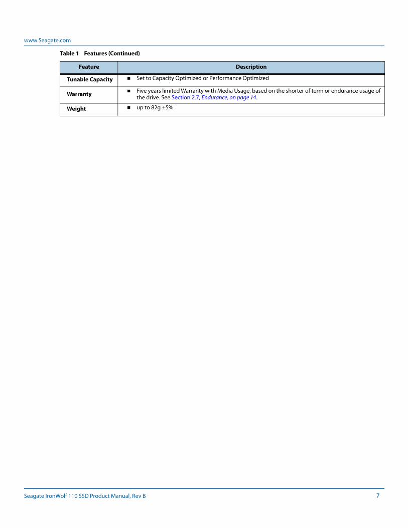
Table 1 Features (Continued)
Feature Description
Seagate IronWolf 110 SSD Product Manual, Rev B 6
www.Seagate.com
Tunable Capacity Set to Capacity Optimized or Performance Optimized
Warranty Five years limited Warranty with Media Usage, based on the shorter of term or endurance usage of the drive. See Section 2.7, Endurance, on page 14.
Weight up to 82g ±5%
Table 1 Features (Continued)
Feature Description
Seagate IronWolf 110 SSD Product Manual, Rev B 7
www.Seagate.com Models and Capacity
2. Specifications
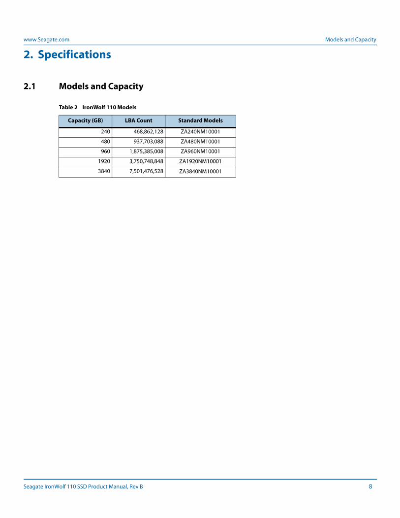
2.1 Models and Capacity
Table 2 IronWolf 110 Models
Capacity (GB) LBA Count Standard Models
240 468,862,128 ZA240NM10001
480 937,703,088 ZA480NM10001
960 1,875,385,008 ZA960NM10001
1920 3,750,748,848 ZA1920NM10001
3840 7,501,476,528 ZA3840NM10001
Seagate IronWolf 110 SSD Product Manual, Rev B 8
www.Seagate.com Performance
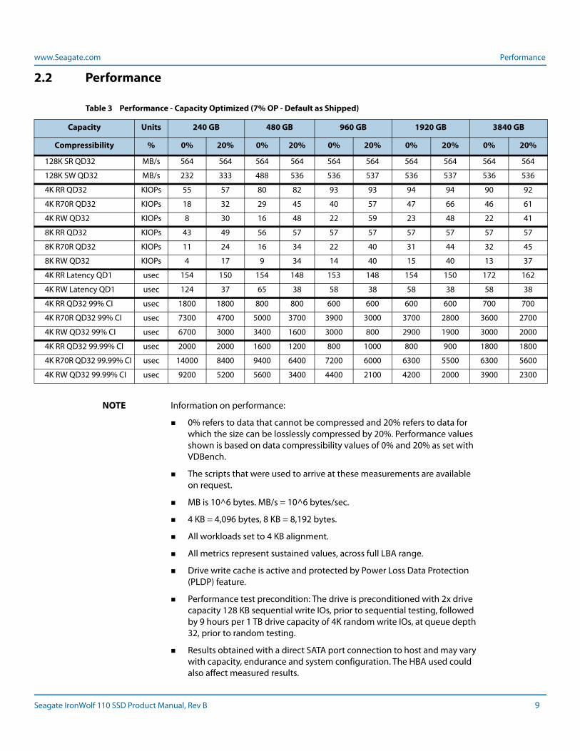
2.2 Performance
NOTE Information on performance:
0% refers to data that cannot be compressed and 20% refers to data for which the size can be losslessly compressed by 20%. Performance values shown is based on data compressibility values of 0% and 20% as set with VDBench.
The scripts that were used to arrive at these measurements are available on request.
MB is 10^6 bytes. MB/s = 10^6 bytes/sec.
4 KB = 4,096 bytes, 8 KB = 8,192 bytes.
All workloads set to 4 KB alignment.
All metrics represent sustained values, across full LBA range.
Drive write cache is active and protected by Power Loss Data Protection (PLDP) feature.
Performance test precondition: The drive is preconditioned with 2x drive capacity 128 KB sequential write IOs, prior to sequential testing, followed by 9 hours per 1 TB drive capacity of 4K random write IOs, at queue depth 32, prior to random testing.
Results obtained with a direct SATA port connection to host and may vary with capacity, endurance and system configuration. The HBA used could also affect measured results.
Table 3 Performance - Capacity Optimized (7% OP - Default as Shipped)
Capacity Units 240 GB 480 GB 960 GB 1920 GB 3840 GB
Compressibility % 0% 20% 0% 20% 0% 20% 0% 20% 0% 20%
128K SR QD32 MB/s 564 564 564 564 564 564 564 564 564 564
128K SW QD32 MB/s 232 333 488 536 536 537 536 537 536 536
4K RR QD32 KIOPs 55 57 80 82 93 93 94 94 90 92
4K R70R QD32 KIOPs 18 32 29 45 40 57 47 66 46 61
4K RW QD32 KIOPs 8 30 16 48 22 59 23 48 22 41
8K RR QD32 KIOPs 43 49 56 57 57 57 57 57 57 57
8K R70R QD32 KIOPs 11 24 16 34 22 40 31 44 32 45
8K RW QD32 KIOPs 4 17 9 34 14 40 15 40 13 37
4K RR Latency QD1 usec 154 150 154 148 153 148 154 150 172 162
4K RW Latency QD1 usec 124 37 65 38 58 38 58 38 58 38
4K RR QD32 99% CI usec 1800 1800 800 800 600 600 600 600 700 700
4K R70R QD32 99% CI usec 7300 4700 5000 3700 3900 3000 3700 2800 3600 2700
4K RW QD32 99% CI usec 6700 3000 3400 1600 3000 800 2900 1900 3000 2000
4K RR QD32 99.99% CI usec 2000 2000 1600 1200 800 1000 800 900 1800 1800
4K R70R QD32 99.99% CI usec 14000 8400 9400 6400 7200 6000 6300 5500 6300 5600
4K RW QD32 99.99% CI usec 9200 5200 5600 3400 4400 2100 4200 2000 3900 2300
Seagate IronWolf 110 SSD Product Manual, Rev B 9
www.Seagate.com Performance
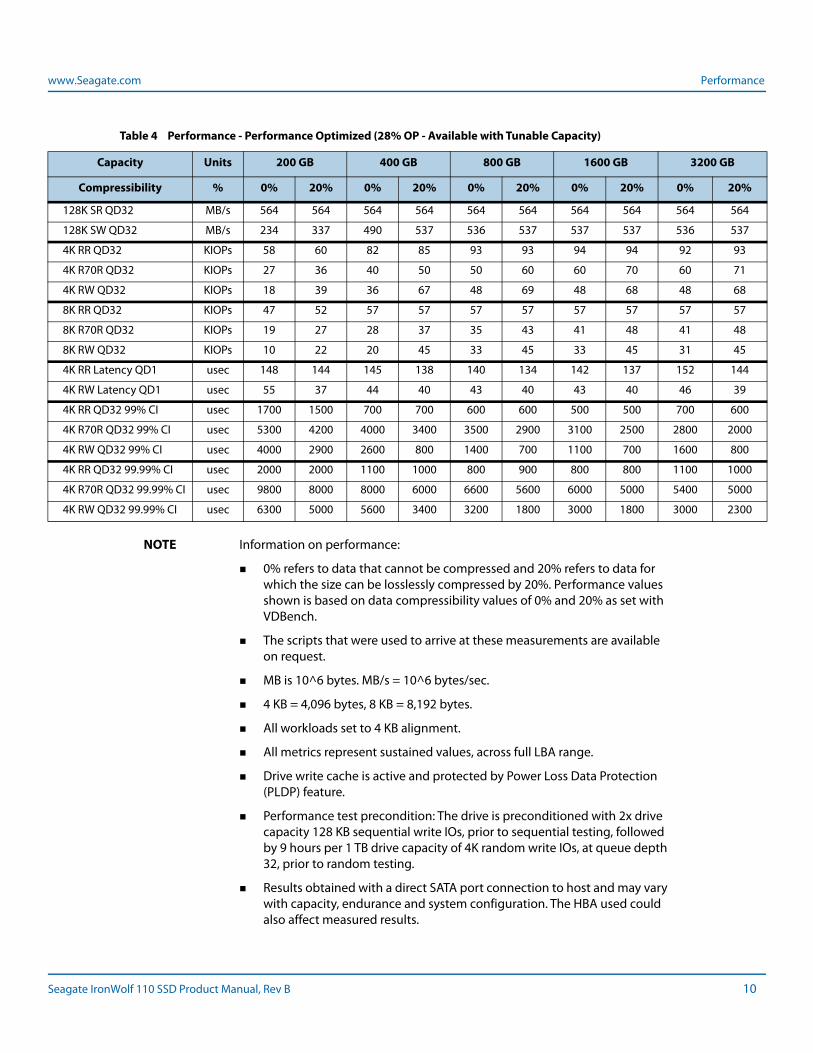
NOTE Information on performance:
0% refers to data that cannot be compressed and 20% refers to data for which the size can be losslessly compressed by 20%. Performance values shown is based on data compressibility values of 0% and 20% as set with VDBench.
The scripts that were used to arrive at these measurements are available on request.
MB is 10^6 bytes. MB/s = 10^6 bytes/sec.
4 KB = 4,096 bytes, 8 KB = 8,192 bytes.
All workloads set to 4 KB alignment.
All metrics represent sustained values, across full LBA range.
Drive write cache is active and protected by Power Loss Data Protection (PLDP) feature.
Performance test precondition: The drive is preconditioned with 2x drive capacity 128 KB sequential write IOs, prior to sequential testing, followed by 9 hours per 1 TB drive capacity of 4K random write IOs, at queue depth 32, prior to random testing.
Results obtained with a direct SATA port connection to host and may vary with capacity, endurance and system configuration. The HBA used could also affect measured results.
Table 4 Performance - Performance Optimized (28% OP - Available with Tunable Capacity)
Capacity Units 200 GB 400 GB 800 GB 1600 GB 3200 GB
Compressibility % 0% 20% 0% 20% 0% 20% 0% 20% 0% 20%
128K SR QD32 MB/s 564 564 564 564 564 564 564 564 564 564
128K SW QD32 MB/s 234 337 490 537 536 537 537 537 536 537
4K RR QD32 KIOPs 58 60 82 85 93 93 94 94 92 93
4K R70R QD32 KIOPs 27 36 40 50 50 60 60 70 60 71
4K RW QD32 KIOPs 18 39 36 67 48 69 48 68 48 68
8K RR QD32 KIOPs 47 52 57 57 57 57 57 57 57 57
8K R70R QD32 KIOPs 19 27 28 37 35 43 41 48 41 48
8K RW QD32 KIOPs 10 22 20 45 33 45 33 45 31 45
4K RR Latency QD1 usec 148 144 145 138 140 134 142 137 152 144
4K RW Latency QD1 usec 55 37 44 40 43 40 43 40 46 39
4K RR QD32 99% CI usec 1700 1500 700 700 600 600 500 500 700 600
4K R70R QD32 99% CI usec 5300 4200 4000 3400 3500 2900 3100 2500 2800 2000
4K RW QD32 99% CI usec 4000 2900 2600 800 1400 700 1100 700 1600 800
4K RR QD32 99.99% CI usec 2000 2000 1100 1000 800 900 800 800 1100 1000
4K R70R QD32 99.99% CI usec 9800 8000 8000 6000 6600 5600 6000 5000 5400 5000
4K RW QD32 99.99% CI usec 6300 5000 5600 3400 3200 1800 3000 1800 3000 2300
Seagate IronWolf 110 SSD Product Manual, Rev B 10
www.Seagate.com Power
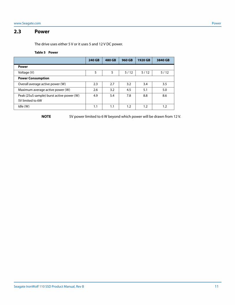
2.3 Power
The drive uses either 5 V or it uses 5 and 12 V DC power.
NOTE 5V power limited to 6 W beyond which power will be drawn from 12 V.
Table 5 Power
240 GB 480 GB 960 GB 1920 GB 3840 GB
Power
Voltage (V) 5 5 5 / 12 5 / 12 5 / 12
Power Consumption
Overall average active power (W) 2.3 2.7 3.2 3.4 3.5
Maximum average active power (W) 2.6 3.2 4.5 5.1 5.0
Peak (25uS sample) burst active power (W)5V limited to 6W
4.9 5.4 7.8 8.8 8.6
Idle (W) 1.1 1.1 1.2 1.2 1.2
Seagate IronWolf 110 SSD Product Manual, Rev B 11
www.Seagate.com Environmental Conditions
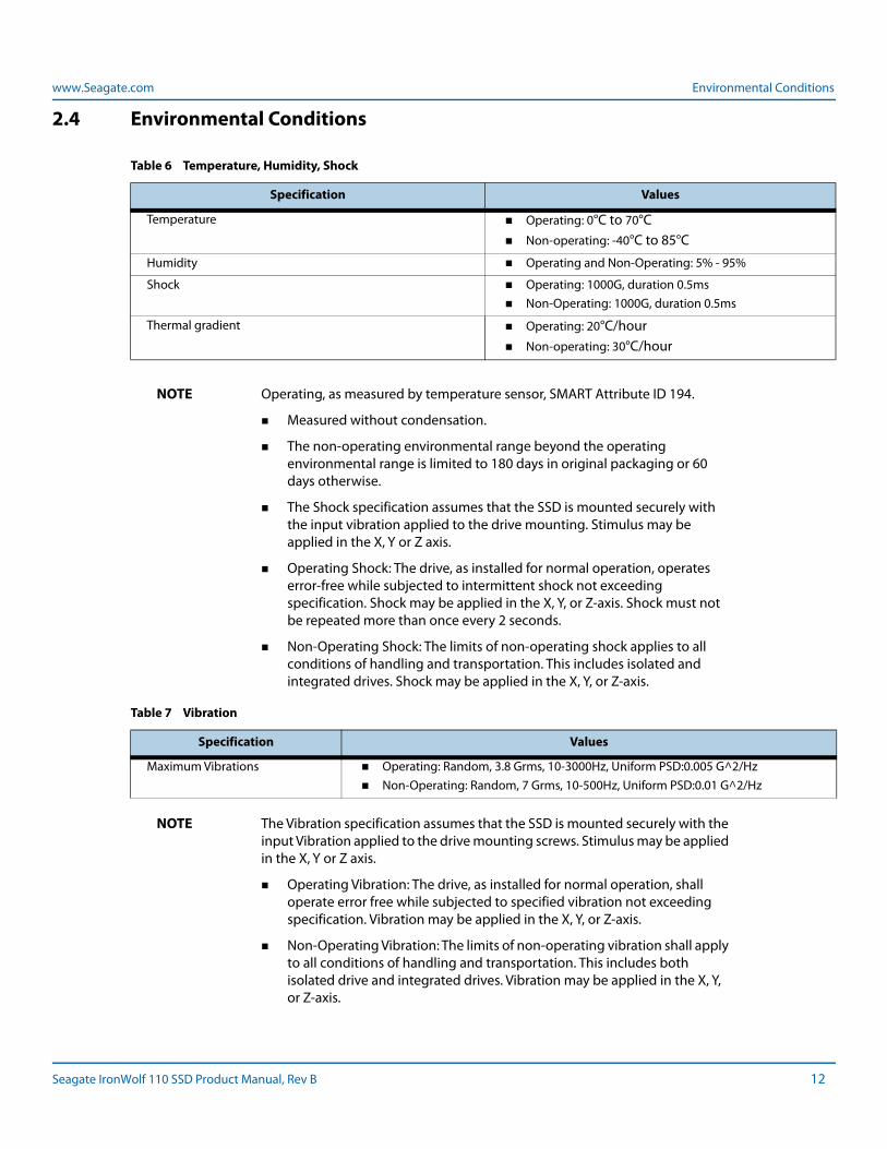
2.4 Environmental Conditions
NOTE Operating, as measured by temperature sensor, SMART Attribute ID 194.
Measured without condensation.
The non-operating environmental range beyond the operating environmental range is limited to 180 days in original packaging or 60 days otherwise.
The Shock specification assumes that the SSD is mounted securely with the input vibration applied to the drive mounting. Stimulus may be applied in the X, Y or Z axis.
Operating Shock: The drive, as installed for normal operation, operates error-free while subjected to intermittent shock not exceeding specification. Shock may be applied in the X, Y, or Z-axis. Shock must not be repeated more than once every 2 seconds.
Non-Operating Shock: The limits of non-operating shock applies to all conditions of handling and transportation. This includes isolated and integrated drives. Shock may be applied in the X, Y, or Z-axis.
NOTE The Vibration specification assumes that the SSD is mounted securely with the input Vibration applied to the drive mounting screws. Stimulus may be applied in the X, Y or Z axis.
Operating Vibration: The drive, as installed for normal operation, shall operate error free while subjected to specified vibration not exceeding specification. Vibration may be applied in the X, Y, or Z-axis.
Non-Operating Vibration: The limits of non-operating vibration shall apply to all conditions of handling and transportation. This includes both isolated drive and integrated drives. Vibration may be applied in the X, Y, or Z-axis.
Table 6 Temperature, Humidity, Shock
Specification Values
Temperature Operating: 0°C to 70°C Non-operating: -40°C to 85°C
Humidity Operating and Non-Operating: 5% - 95%
Shock Operating: 1000G, duration 0.5ms Non-Operating: 1000G, duration 0.5ms
Thermal gradient Operating: 20°C/hour Non-operating: 30°C/hour
Table 7 Vibration
Specification Values
Maximum Vibrations Operating: Random, 3.8 Grms, 10-3000Hz, Uniform PSD:0.005 G^2/Hz Non-Operating: Random, 7 Grms, 10-500Hz, Uniform PSD:0.01 G^2/Hz
Seagate IronWolf 110 SSD Product Manual, Rev B 12
www.Seagate.com Reliability
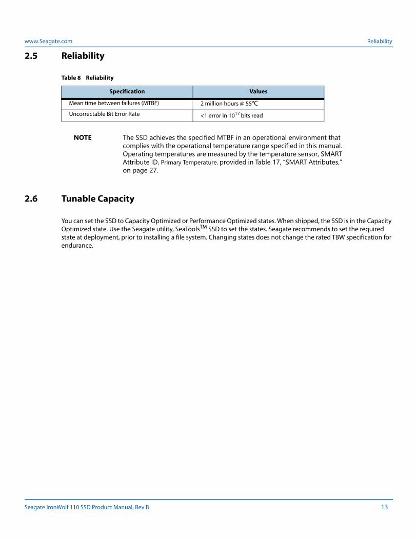
2.5 Reliability
NOTE The SSD achieves the specified MTBF in an operational environment that complies with the operational temperature range specified in this manual. Operating temperatures are measured by the temperature sensor, SMART Attribute ID, Primary Temperature, provided in Table 17, “SMART Attributes,” on page 27.
2.6 Tunable Capacity
You can set the SSD to Capacity Optimized or Performance Optimized states. When shipped, the SSD is in the Capacity Optimized state. Use the Seagate utility, SeaToolsTM SSD to set the states. Seagate recommends to set the required state at deployment, prior to installing a file system. Changing states does not change the rated TBW specification for endurance.
Table 8 Reliability
Specification Values
Mean time between failures (MTBF) 2 million hours @ 55°C
Uncorrectable Bit Error Rate <1 error in 1017 bits read
Seagate IronWolf 110 SSD Product Manual, Rev B 13
www.Seagate.com Endurance
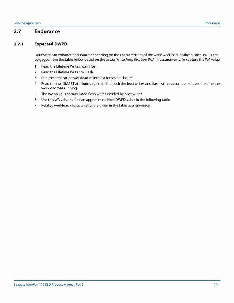
2.7 Endurance
2.7.1 Expected DWPD
DuraWrite can enhance endurance depending on the characteristics of the write workload. Realized Host DWPD can be gaged from the table below based on the actual Write Amplification (WA) measurements. To capture the WA value:
1. Read the Lifetime Writes from Host.
2. Read the Lifetime Writes to Flash.
3. Run the application workload of interest for several hours.
4. Read the two SMART attributes again to find both the host writes and flash writes accumulated over the time the workload was running.
5. The WA value is accumulated flash writes divided by host writes.
6. Use this WA value to find an approximate Host DWPD value in the following table.
7. Related workload characteristics are given in the table as a reference.
Seagate IronWolf 110 SSD Product Manual, Rev B 14
www.Seagate.com Endurance
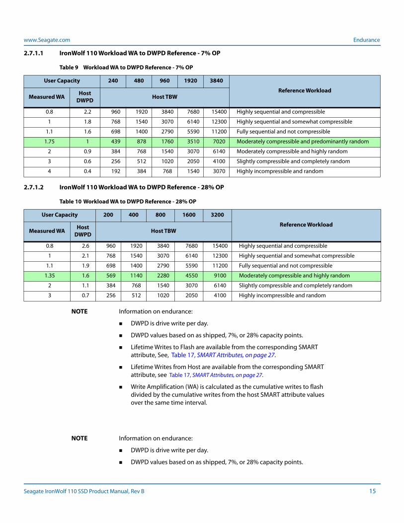
2.7.1.1 IronWolf 110 Workload WA to DWPD Reference - 7% OP
2.7.1.2 IronWolf 110 Workload WA to DWPD Reference - 28% OP
NOTE Information on endurance:
DWPD is drive write per day.
DWPD values based on as shipped, 7%, or 28% capacity points.
Lifetime Writes to Flash are available from the corresponding SMART attribute, See, Table 17, SMART Attributes, on page 27.
Lifetime Writes from Host are available from the corresponding SMART attribute, see Table 17, SMART Attributes, on page 27.
Write Amplification (WA) is calculated as the cumulative writes to flash divided by the cumulative writes from the host SMART attribute values over the same time interval.
NOTE Information on endurance:
DWPD is drive write per day.
DWPD values based on as shipped, 7%, or 28% capacity points.
Table 9 Workload WA to DWPD Reference - 7% OP
User Capacity 240 480 960 1920 3840
Reference WorkloadMeasured WA Host
DWPD Host TBW
0.8 2.2 960 1920 3840 7680 15400 Highly sequential and compressible
1 1.8 768 1540 3070 6140 12300 Highly sequential and somewhat compressible
1.1 1.6 698 1400 2790 5590 11200 Fully sequential and not compressible
1.75 1 439 878 1760 3510 7020 Moderately compressible and predominantly random
2 0.9 384 768 1540 3070 6140 Moderately compressible and highly random
3 0.6 256 512 1020 2050 4100 Slightly compressible and completely random
4 0.4 192 384 768 1540 3070 Highly incompressible and random
Table 10 Workload WA to DWPD Reference - 28% OP
User Capacity 200 400 800 1600 3200
Reference WorkloadMeasured WA Host
DWPD Host TBW
0.8 2.6 960 1920 3840 7680 15400 Highly sequential and compressible
1 2.1 768 1540 3070 6140 12300 Highly sequential and somewhat compressible
1.1 1.9 698 1400 2790 5590 11200 Fully sequential and not compressible
1.35 1.6 569 1140 2280 4550 9100 Moderately compressible and highly random
2 1.1 384 768 1540 3070 6140 Slightly compressible and completely random
3 0.7 256 512 1020 2050 4100 Highly incompressible and random
Seagate IronWolf 110 SSD Product Manual, Rev B 15
www.Seagate.com Endurance
Lifetime Writes to Flash are available from the corresponding SMART attribute, See, Table 17, SMART Attributes, on page 27.
Lifetime Writes from Host are available from the corresponding SMART attribute, see Table 17, SMART Attributes, on page 27.
Write Amplification (WA) is calculated as the cumulative writes to flash divided by the cumulative writes from the host SMART attribute values over the same time interval.
Seagate IronWolf 110 SSD Product Manual, Rev B 16
www.Seagate.com Endurance
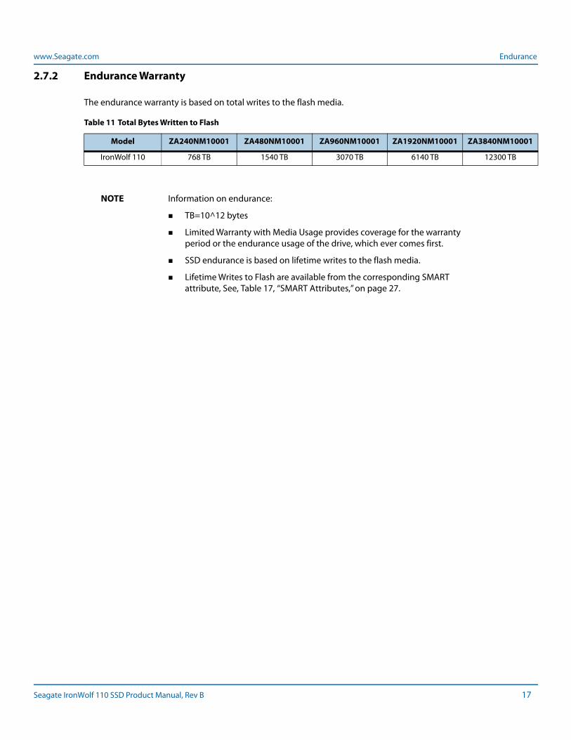
2.7.2 Endurance Warranty
The endurance warranty is based on total writes to the flash media.
NOTE Information on endurance:
TB=10^12 bytes
Limited Warranty with Media Usage provides coverage for the warranty period or the endurance usage of the drive, which ever comes first.
SSD endurance is based on lifetime writes to the flash media.
Lifetime Writes to Flash are available from the corresponding SMART attribute, See, Table 17, “SMART Attributes,” on page 27.
Table 11 Total Bytes Written to Flash
Model ZA240NM10001 ZA480NM10001 ZA960NM10001 ZA1920NM10001 ZA3840NM10001
IronWolf 110 768 TB 1540 TB 3070 TB 6140 TB 12300 TB
Seagate IronWolf 110 SSD Product Manual, Rev B 17
www.Seagate.com Dimensions and Weight
3. Mechanical Information
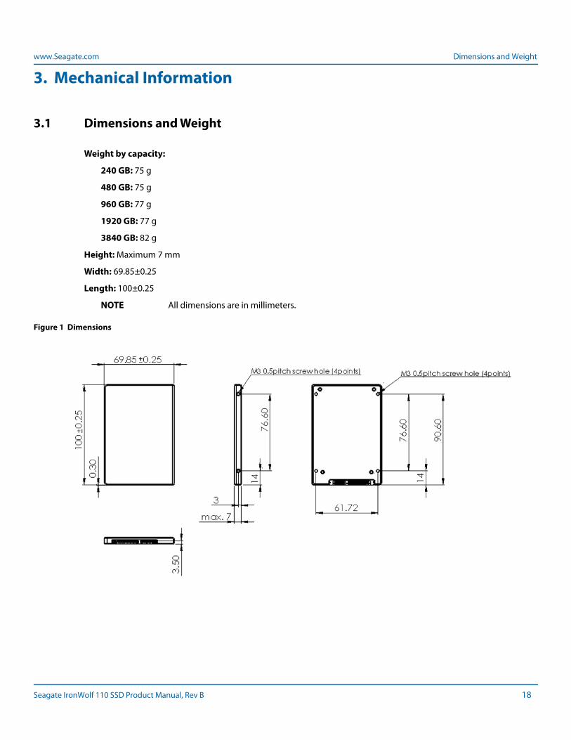
3.1 Dimensions and Weight
Weight by capacity:
240 GB: 75 g
480 GB: 75 g
960 GB: 77 g
1920 GB: 77 g
3840 GB: 82 g
Height: Maximum 7 mm
Width: 69.85±0.25
Length: 100±0.25
NOTE All dimensions are in millimeters.
Figure 1 Dimensions
Seagate IronWolf 110 SSD Product Manual, Rev B 18
www.Seagate.com Serial ATA Interface Connector
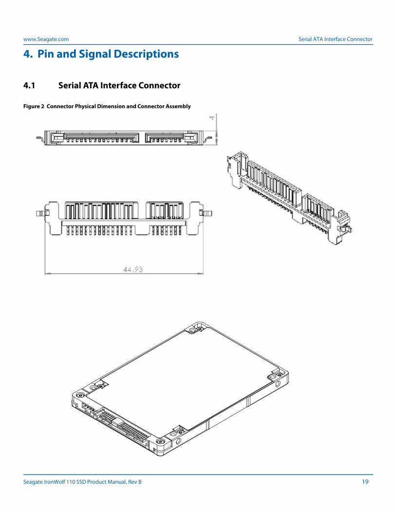
4. Pin and Signal Descriptions
4.1 Serial ATA Interface Connector
Figure 2 Connector Physical Dimension and Connector Assembly
Seagate IronWolf 110 SSD Product Manual, Rev B 19
www.Seagate.com Pin Locations
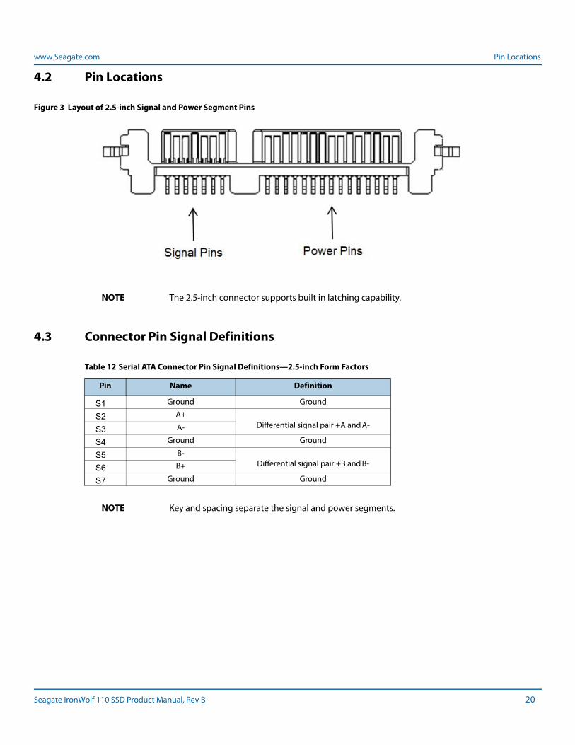
4.2 Pin Locations
Figure 3 Layout of 2.5-inch Signal and Power Segment Pins
NOTE The 2.5-inch connector supports built in latching capability.
4.3 Connector Pin Signal Definitions
NOTE Key and spacing separate the signal and power segments.
Table 12 Serial ATA Connector Pin Signal Definitions—2.5-inch Form Factors
Pin Name Definition
S1 Ground Ground
S2 A+Differential signal pair +A and A-S3 A-
S4 Ground Ground
S5 B-Differential signal pair +B and B-S6 B+
S7 Ground Ground
Seagate IronWolf 110 SSD Product Manual, Rev B 20
www.Seagate.com Power Pin Signal Definitions
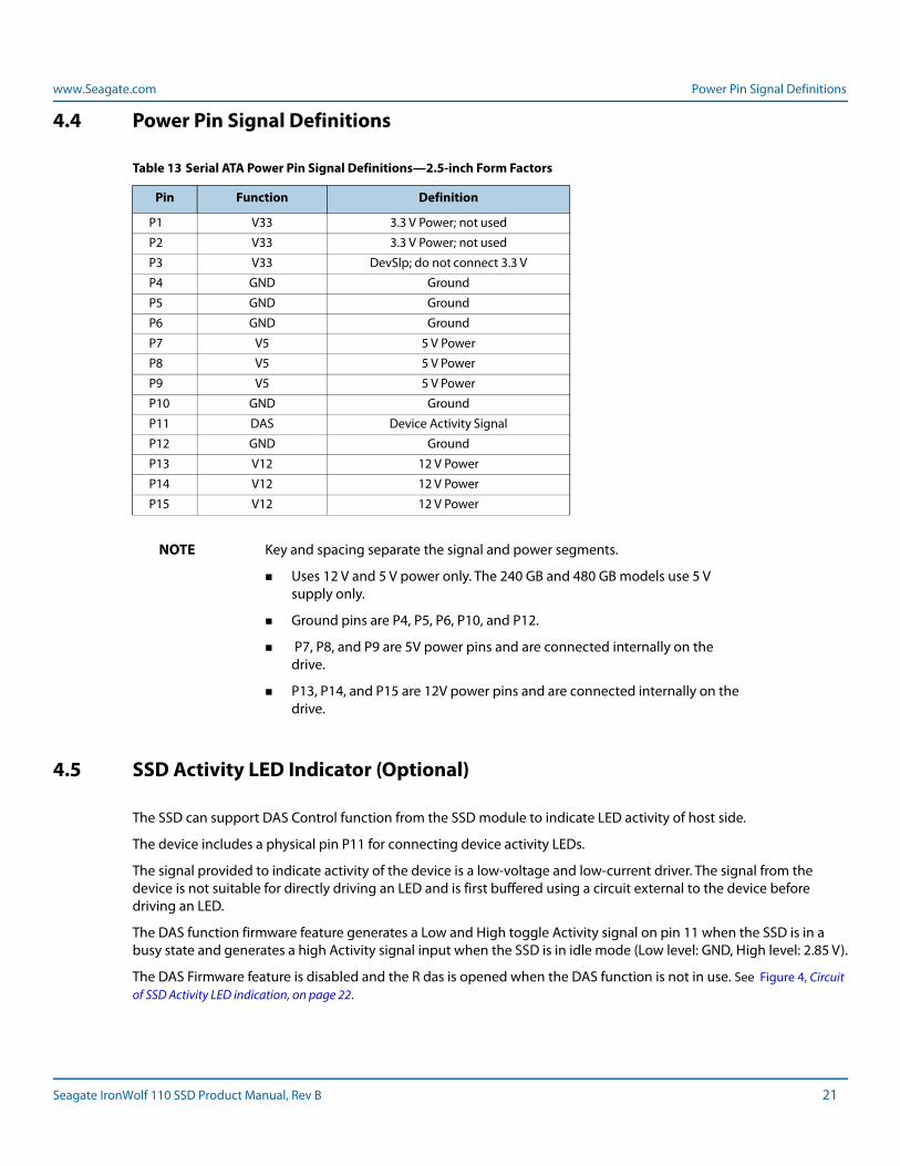
4.4 Power Pin Signal Definitions
NOTE Key and spacing separate the signal and power segments.
Uses 12 V and 5 V power only. The 240 GB and 480 GB models use 5 V supply only.
Ground pins are P4, P5, P6, P10, and P12.
P7, P8, and P9 are 5V power pins and are connected internally on the drive.
P13, P14, and P15 are 12V power pins and are connected internally on the drive.
4.5 SSD Activity LED Indicator (Optional)
The SSD can support DAS Control function from the SSD module to indicate LED activity of host side.
The device includes a physical pin P11 for connecting device activity LEDs.
The signal provided to indicate activity of the device is a low-voltage and low-current driver. The signal from the device is not suitable for directly driving an LED and is first buffered using a circuit external to the device before driving an LED.
The DAS function firmware feature generates a Low and High toggle Activity signal on pin 11 when the SSD is in a busy state and generates a high Activity signal input when the SSD is in idle mode (Low level: GND, High level: 2.85 V).
The DAS Firmware feature is disabled and the R das is opened when the DAS function is not in use. See Figure 4, Circuit of SSD Activity LED indication, on page 22.
Table 13 Serial ATA Power Pin Signal Definitions—2.5-inch Form Factors
Pin Function Definition
P1 V33 3.3 V Power; not used
P2 V33 3.3 V Power; not used
P3 V33 DevSlp; do not connect 3.3 V
P4 GND Ground
P5 GND Ground
P6 GND Ground
P7 V5 5 V Power
P8 V5 5 V Power
P9 V5 5 V Power
P10 GND Ground
P11 DAS Device Activity Signal
P12 GND Ground
P13 V12 12 V Power
P14 V12 12 V Power
P15 V12 12 V Power
Seagate IronWolf 110 SSD Product Manual, Rev B 21
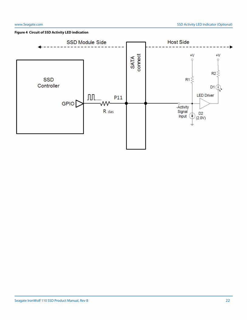
www.Seagate.com SSD Activity LED Indicator (Optional)
Figure 4 Circuit of SSD Activity LED indication
Seagate IronWolf 110 SSD Product Manual, Rev B 22
www.Seagate.com ATA Feature Set
5. Supported ATA Command List
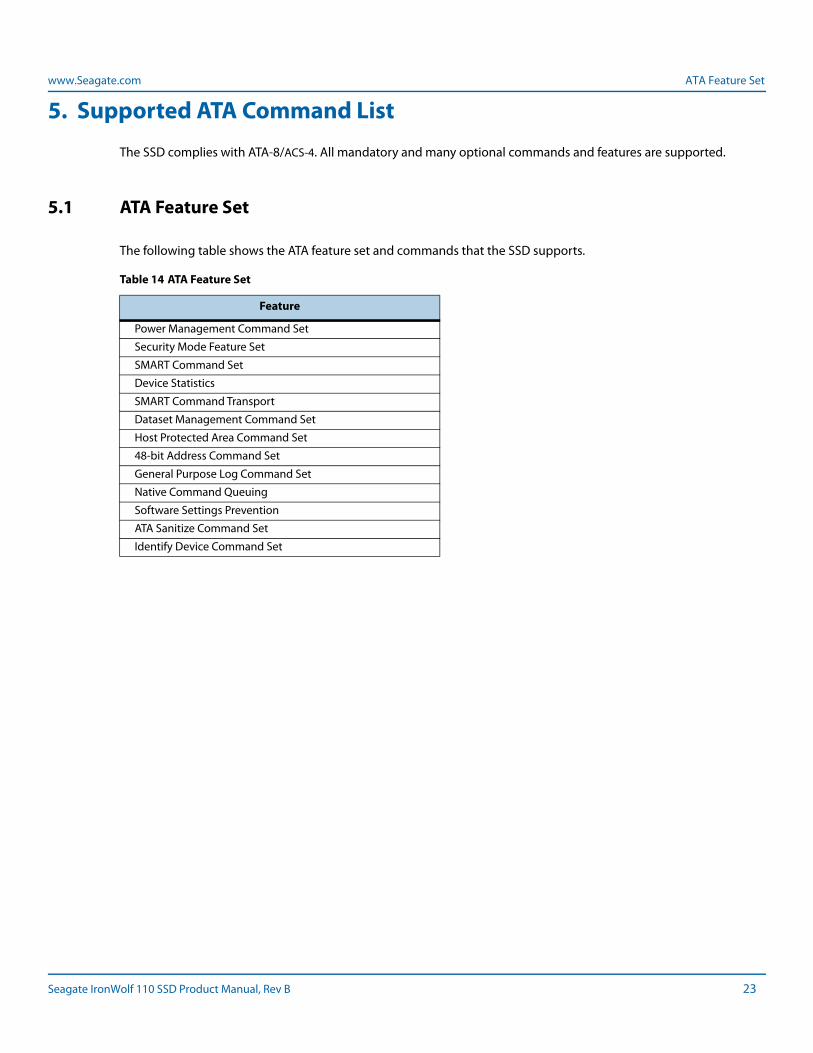
The SSD complies with ATA-8/ACS-4. All mandatory and many optional commands and features are supported.
5.1 ATA Feature Set
The following table shows the ATA feature set and commands that the SSD supports.
Table 14 ATA Feature Set
Feature
Power Management Command Set
Security Mode Feature Set
SMART Command Set
Device Statistics
SMART Command Transport
Dataset Management Command Set
Host Protected Area Command Set
48-bit Address Command Set
General Purpose Log Command Set
Native Command Queuing
Software Settings Prevention
ATA Sanitize Command Set
Identify Device Command Set
Seagate IronWolf 110 SSD Product Manual, Rev B 23
www.Seagate.com ATA Command Description
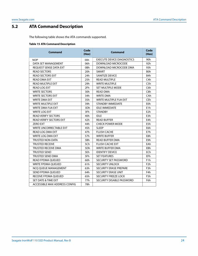
5.2 ATA Command Description
The following table shows the ATA commands supported.
Table 15 ATA Command Description
Command Code (Hex) Command Code
(Hex)
NOP 00h EXECUTE DEVICE DIAGNOSTICS 90hDATA SET MANAGEMENT 06h DOWNLOAD MICROCODE 92hREQUEST SENSE DATA EXT 0Bh DOWNLOAD MICROCODE DMA 93hREAD SECTORS 20h SMART B0hREAD SECTORS EXT 24h SANITIZE DEVICE B4hREAD DMA EXT 25h READ MULTIPLE C4hREAD MULTIPLE EXT 29h WRITE MULTIPLE C5hREAD LOG EXT 2Fh SET MULTIPLE MODE C6hWRITE SECTORS 30h READ DMA C8hWRITE SECTORS EXT 34h WRITE DMA CAhWRITE DMA EXT 35h WRITE MULTIPLE FUA EXT CEhWRITE MULTIPLE EXT 39h STANDBY IMMEDIATE E0hWRITE DMA FUA EXT 3Dh IDLE IMMEDIATE E1hWRITE LOG EXT 3Fh STANDBY E2hREAD VERIFY SECTORS 40h IDLE E3hREAD VERIFY SECTORS EXT 42h READ BUFFER E4hZERO EXT 44h CHECK POWER MODE E5hWRITE UNCORRECTABLE EXT 45h SLEEP E6hREAD LOG DMA EXT 47h FLUSH CACHE E7hWRITE LOG DMA EXT 57h WRITE BUFFER E8hTRUSTED NON-DATA 5Bh READ BUFFER DMA E9hTRUSTED RECEIVE 5Ch FLUSH CACHE EXT EAhTRUSTED RECEIVE DMA 5Dh WRITE BUFFER DMA EBhTRUSTED SEND 5Eh IDENTIFY DEVICE EChTRUSTED SEND DMA 5Fh SET FEATURES EFhREAD FPDMA QUEUED 60h SECURITY SET PASSWORD F1hWRITE FPDMA QUEUED 61h SECURITY UNLOCK F2hNCQ QUEUE MANAGEMENT 63h SECURITY ERASE PREPARE F3hSEND FPDMA QUEUED 64h SECURITY ERASE UNIT F4hRECEIVE FPDMA QUEUED 65h SECURITY FREEZE LOCK F5hSET DATE & TIME EXT 77h SECURITY DISABLE PASSWORD F6hACCESSIBLE MAX ADDRESS CONFIG 78h
Seagate IronWolf 110 SSD Product Manual, Rev B 24
www.Seagate.com Security
5.3 Security
The user/master password is supported.
When the device receives a normal SECURITY ERASE UNIT command, the device erases all data blocks including unallocated (hidden) blocks.
You can download firmware regardless of the security state.
Other security features:
Crypto-erase sanitization
Block-level sanitization
Secure update of firmware
5.3.1 Password Loss
If you lose the user password, you can access the device using the master password. If both passwords are lost, there is no way to access the device.
Seagate IronWolf 110 SSD Product Manual, Rev B 25
www.Seagate.com SMART Command Set
6. SMART Support
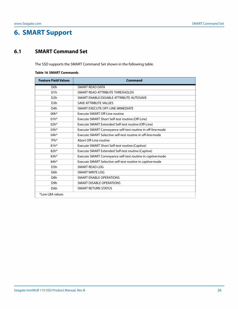
6.1 SMART Command Set
The SSD supports the SMART Command Set shown in the following table.
Table 16 SMART Commands
Feature Field Values Command
D0h SMART READ DATA
D1h SMART READ ATTRIBUTE THRESHOLDS
D2h SMART ENABLE/DISABLE ATTRIBUTE AUTOSAVE
D3h SAVE ATTRIBUTE VALUES
D4h SMART EXECUTE OFF-LINE IMMEDIATE
00h* Execute SMART Off-Line routine
01h* Execute SMART Short Self-test routine (Off-Line)
02h* Execute SMART Extended Self-test routine (Off-Line)
03h* Execute SMART Conveyance self-test routine in off-line mode
04h* Execute SMART Selective self-test routine in off-line mode
7Fh* Abort Off-Line routine
81h* Execute SMART Short Self-test routine (Captive)
82h* Execute SMART Extended Self-test routine (Captive)
83h* Execute SMART Conveyance self-test routine in captive mode
84h* Execute SMART Selective self-test routine in captive mode
D5h SMART READ LOG
D6h SMART WRITE LOG
D8h SMART ENABLE OPERATIONS
D9h SMART DISABLE OPERATIONS
DAh SMART RETURN STATUS
*Low LBA values
Seagate IronWolf 110 SSD Product Manual, Rev B 26
www.Seagate.com SMART Attributes
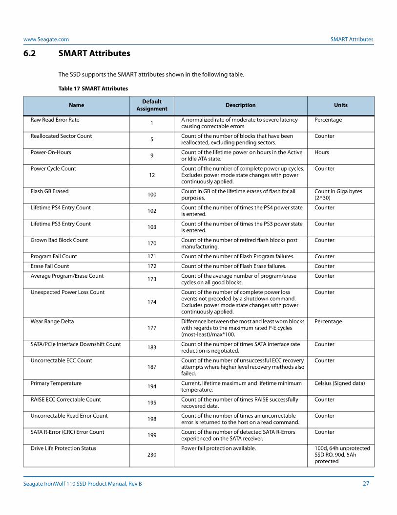
6.2 SMART Attributes
The SSD supports the SMART attributes shown in the following table.
Table 17 SMART Attributes
Name Default Assignment Description Units
Raw Read Error Rate 1 A normalized rate of moderate to severe latency causing correctable errors.
Percentage
Reallocated Sector Count 5 Count of the number of blocks that have been reallocated, excluding pending sectors.
Counter
Power-On-Hours 9 Count of the lifetime power on hours in the Active or Idle ATA state.
Hours
Power Cycle Count12
Count of the number of complete power up cycles. Excludes power mode state changes with power continuously applied.
Counter
Flash GB Erased 100 Count in GB of the lifetime erases of flash for all purposes.
Count in Giga bytes (2^30)
Lifetime PS4 Entry Count 102 Count of the number of times the PS4 power state is entered.
Counter
Lifetime PS3 Entry Count 103 Count of the number of times the PS3 power state is entered.
Counter
Grown Bad Block Count 170 Count of the number of retired flash blocks post manufacturing.
Counter
Program Fail Count 171 Count of the number of Flash Program failures. Counter
Erase Fail Count 172 Count of the number of Flash Erase failures. Counter
Average Program/Erase Count 173 Count of the average number of program/erase cycles on all good blocks.
Counter
Unexpected Power Loss Count
174
Count of the number of complete power loss events not preceded by a shutdown command. Excludes power mode state changes with power continuously applied.
Counter
Wear Range Delta177
Difference between the most and least worn blocks with regards to the maximum rated P-E cycles (most-least)/max*100.
Percentage
SATA/PCIe Interface Downshift Count 183 Count of the number of times SATA interface rate reduction is negotiated.
Counter
Uncorrectable ECC Count187
Count of the number of unsuccessful ECC recovery attempts where higher level recovery methods also failed.
Counter
Primary Temperature 194 Current, lifetime maximum and lifetime minimum temperature.
Celsius (Signed data)
RAISE ECC Correctable Count 195 Count of the number of times RAISE successfully recovered data.
Counter
Uncorrectable Read Error Count 198 Count of the number of times an uncorrectable error is returned to the host on a read command.
Counter
SATA R-Error (CRC) Error Count 199 Count of the number of detected SATA R-Errors experienced on the SATA receiver.
Counter
Drive Life Protection Status230
Power fail protection available. 100d, 64h unprotected SSD RO, 90d, 5Ah protected
Seagate IronWolf 110 SSD Product Manual, Rev B 27
www.Seagate.com SMART Trip
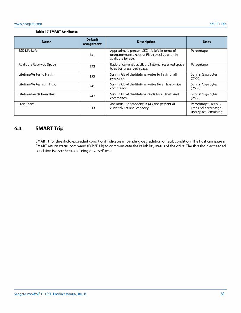
6.3 SMART Trip
SMART trip (threshold exceeded condition) indicates impending degradation or fault condition. The host can issue a SMART return status command (B0h/DAh) to communicate the reliability status of the drive. The threshold-exceeded condition is also checked during drive self tests.
SSD Life Left231
Approximate percent SSD life left, in terms of program/erase cycles or Flash blocks currently available for use.
Percentage
Available Reserved Space 232 Ratio of currently available internal reserved space to as built reserved space.
Percentage
Lifetime Writes to Flash 233 Sum in GB of the lifetime writes to flash for all purposes.
Sum in Giga bytes (2^30)
Lifetime Writes from Host 241 Sum in GB of the lifetime writes for all host write commands.
Sum in Giga bytes (2^30)
Lifetime Reads from Host 242 Sum in GB of the lifetime reads for all host read commands.
Sum in Giga bytes (2^30)
Free Space243
Available user capacity in MB and percent of currently set user capacity.
Percentage User MB Free and percentage user space remaining
Table 17 SMART Attributes
Name Default Assignment Description Units
Seagate IronWolf 110 SSD Product Manual, Rev B 28
www.Seagate.com Regulatory Model Number
7. Safety and Compliance Standards
Each Hard Drive and Solid State Drive ("device") has a product label that includes certifications that apply to
that specific drive. The following information provides an overview of requirements that may apply to the
drive.
The Seagate HDD and SSD Regularity Compliance and Safety document contains the latest regulations and standards
that Seagate complies with. To see this document, go online here:
https://www.seagate.com/files/www-content/forms/compliance/regulatory-compliance-and-safety-100838899-A.pdf
7.1 Regulatory Model Number
The following regulatory model number represents all features and configurations within the series:
NOTE STA010
Seagate IronWolf 110 SSD Product Manual, Rev B 29
Seagate Technology LLCAMERICAS Seagate Technology LLC 10200 South De Anza Boulevard, Cupertino, California 95014, United States, 408-658-1000ASIA/PACIFIC Seagate Singapore International Headquarters Pte. Ltd. 7000 Ang Mo Kio Avenue 5, Singapore 569877, 65-6485-3888EUROPE, MIDDLE EAST, AND AFRICA Seagate Technology SAS 16-18 rue du Dôme, 92100 Boulogne-Billancourt, France, 33 1-4186 10 00Publication Number: 100841919, Rev BAugust 2019,