SE310 Analysis and Design of Software...
22
March 21, 2018 Sam Siewert SE310 Analysis and Design of Software Systems Lecture 11 – Presentation of Analysis and Design [Level-0,1,2,3]
Transcript of SE310 Analysis and Design of Software...
March 21, 2018 Sam Siewert
SE310 Analysis and Design of Software
Systems
Lecture 11 – Presentation of Analysis and Design
[Level-0,1,2,3]

Reminders Assignment #5
Assignment #5 & #6 Posted – Questions? Exercise #6 is your Final Report No Exam #2 - Study Notes for Quizzes and Use in Design Final Exam – Your Group Presentation – http://mercury.pr.erau.edu/~siewerts/se310/assignments/SWE-
310-Design-Teams.pdf – All Materials Found HERE
Sam Siewert 2

Design Walkthrough - Strategy Top N Capability Oriented Requirements
– State and Explain – Hold Q&A and Ask for Reviewer Input on Completeness, Errors and Omissions
Single Page High Level Block Diagram of Software System
– Show End-to-End Elements and Dataflow – Source to Sink (Top Left Corner to Bottom Right)
Use Case(s), Component (Module) Diagram, CRC Classes [Level 0] CFD/DFD [Level 1] Domain Class Diagram [Level 1] OIM Sequence Diagram [Level 2] State Machines, Activity Diagrams, Flowcharts [Level 3]
Sam Siewert 3
Team Status Reports – Level-0 Roles – Scrum Leader for Sprint on Assignment #4 – Brief Statement of Role by Each Team Member this Sprint
Status – Capability Requirements – High Level Block Diagram, CFD/DFD, Other …
Roadblocks Next Steps …
Sam Siewert 4

Level 0 - Analysis From Concept to Analysis prior to Architecture Requirements – First Cut Use Cases Tracing of UC to Requirements CRC – Class Responsibility Collaborator Model
Sam Siewert 5

Level 1 - Architecture From Analysis to Architecture prior to System Design Requirements – Refinement based on L0 Reviews Use Cases – Refinement and Acceptance Tests Major Components (Modules) and Component, Package, Deployment Diagrams Class Diagram – Methods and Attribute Refinement with Emphasis on Relationships
– Association (1…*, 1…1, 0…n, *…*) – Inheritance (Sub-class refines parent class attributes and methods) – Container (Class contains class or classes) – Aggregation (Class comprises part of another class)
OIM Sequence Diagrams – First Cut
– Class instantiation and methods for objects to communicate, synchronize and complete a UC
– Positive and Negative – Focus on Positive – Supports further Class method refinement – Defines Processing Sam Siewert 6
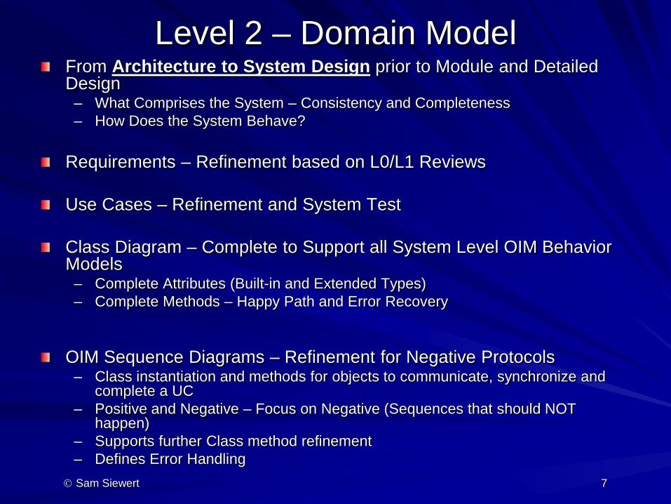
Level 2 – Domain Model From Architecture to System Design prior to Module and Detailed Design
– What Comprises the System – Consistency and Completeness – How Does the System Behave?
Requirements – Refinement based on L0/L1 Reviews Use Cases – Refinement and System Test Class Diagram – Complete to Support all System Level OIM Behavior Models
– Complete Attributes (Built-in and Extended Types) – Complete Methods – Happy Path and Error Recovery
OIM Sequence Diagrams – Refinement for Negative Protocols – Class instantiation and methods for objects to communicate, synchronize and
complete a UC – Positive and Negative – Focus on Negative (Sequences that should NOT
happen) – Supports further Class method refinement – Defines Error Handling
Sam Siewert 7
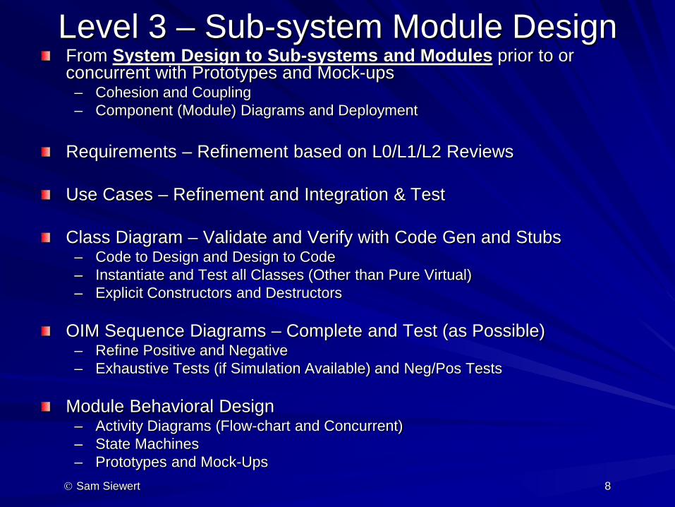
Level 3 – Sub-system Module Design From System Design to Sub-systems and Modules prior to or concurrent with Prototypes and Mock-ups
– Cohesion and Coupling – Component (Module) Diagrams and Deployment
Requirements – Refinement based on L0/L1/L2 Reviews Use Cases – Refinement and Integration & Test Class Diagram – Validate and Verify with Code Gen and Stubs
– Code to Design and Design to Code – Instantiate and Test all Classes (Other than Pure Virtual) – Explicit Constructors and Destructors
OIM Sequence Diagrams – Complete and Test (as Possible) – Refine Positive and Negative – Exhaustive Tests (if Simulation Available) and Neg/Pos Tests
Module Behavioral Design
– Activity Diagrams (Flow-chart and Concurrent) – State Machines – Prototypes and Mock-Ups
Sam Siewert 8
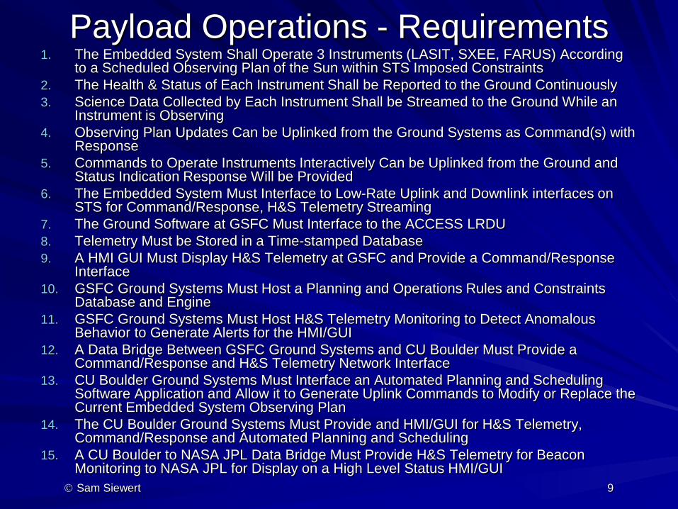
Payload Operations - Requirements 1. The Embedded System Shall Operate 3 Instruments (LASIT, SXEE, FARUS) According
to a Scheduled Observing Plan of the Sun within STS Imposed Constraints 2. The Health & Status of Each Instrument Shall be Reported to the Ground Continuously 3. Science Data Collected by Each Instrument Shall be Streamed to the Ground While an
Instrument is Observing 4. Observing Plan Updates Can be Uplinked from the Ground Systems as Command(s) with
Response 5. Commands to Operate Instruments Interactively Can be Uplinked from the Ground and
Status Indication Response Will be Provided 6. The Embedded System Must Interface to Low-Rate Uplink and Downlink interfaces on
STS for Command/Response, H&S Telemetry Streaming 7. The Ground Software at GSFC Must Interface to the ACCESS LRDU 8. Telemetry Must be Stored in a Time-stamped Database 9. A HMI GUI Must Display H&S Telemetry at GSFC and Provide a Command/Response
Interface 10. GSFC Ground Systems Must Host a Planning and Operations Rules and Constraints
Database and Engine 11. GSFC Ground Systems Must Host H&S Telemetry Monitoring to Detect Anomalous
Behavior to Generate Alerts for the HMI/GUI 12. A Data Bridge Between GSFC Ground Systems and CU Boulder Must Provide a
Command/Response and H&S Telemetry Network Interface 13. CU Boulder Ground Systems Must Interface an Automated Planning and Scheduling
Software Application and Allow it to Generate Uplink Commands to Modify or Replace the Current Embedded System Observing Plan
14. The CU Boulder Ground Systems Must Provide and HMI/GUI for H&S Telemetry, Command/Response and Automated Planning and Scheduling
15. A CU Boulder to NASA JPL Data Bridge Must Provide H&S Telemetry for Beacon Monitoring to NASA JPL for Display on a High Level Status HMI/GUI
Sam Siewert 9

Hardware End-to-End System DATA Hitchhiker Payload, flown STS-85, Summer 1997 Designed, Built and Operated by U. of Colorado Students
Sam Siewert 10

Software End-to-End System
Sam Siewert 11
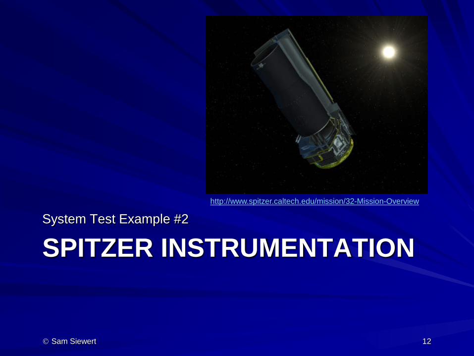
SPITZER INSTRUMENTATION System Test Example #2
Sam Siewert 12
http://www.spitzer.caltech.edu/mission/32-Mission-Overview
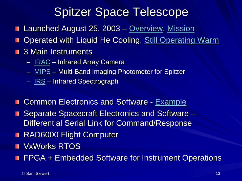
Spitzer Space Telescope Launched August 25, 2003 – Overview, Mission Operated with Liquid He Cooling, Still Operating Warm 3 Main Instruments – IRAC – Infrared Array Camera – MIPS – Multi-Band Imaging Photometer for Spitzer – IRS – Infrared Spectrograph
Common Electronics and Software - Example Separate Spacecraft Electronics and Software – Differential Serial Link for Command/Response RAD6000 Flight Computer VxWorks RTOS FPGA + Embedded Software for Instrument Operations
Sam Siewert 13

Discussion and Q&A System Testing – Entrance Criteria [When is I&T Complete?] – Of All Recognized System Test Types, Which are Critical to My
Organization? Wikipedia on System Test Types Select Focus in System Testing Based on System Requirements and Product
– Exit Criteria SQA Process – Documentation, Audits, Improvement – Certifications for QA and SQA Process
ISO 9000 QA SEI CMM Levels 3 … 5, Etc. as determined by CMMI, Companies at each Level
– Is Process Documented? Repeatable? Can it Be Improved? Automated? Verifiable Criteria? [E.g. Code Coverage Tool Records]
– Does Certification Matter? Who Does Audits? – Current Issue – How are Auditors Accountable?
Sam Siewert 14

DRONE NET - SMALL UAS DETECTION AND TRACKING
System Test Example #3
Sam Siewert 15
IEEE Aerospace Drone Net System Architecture
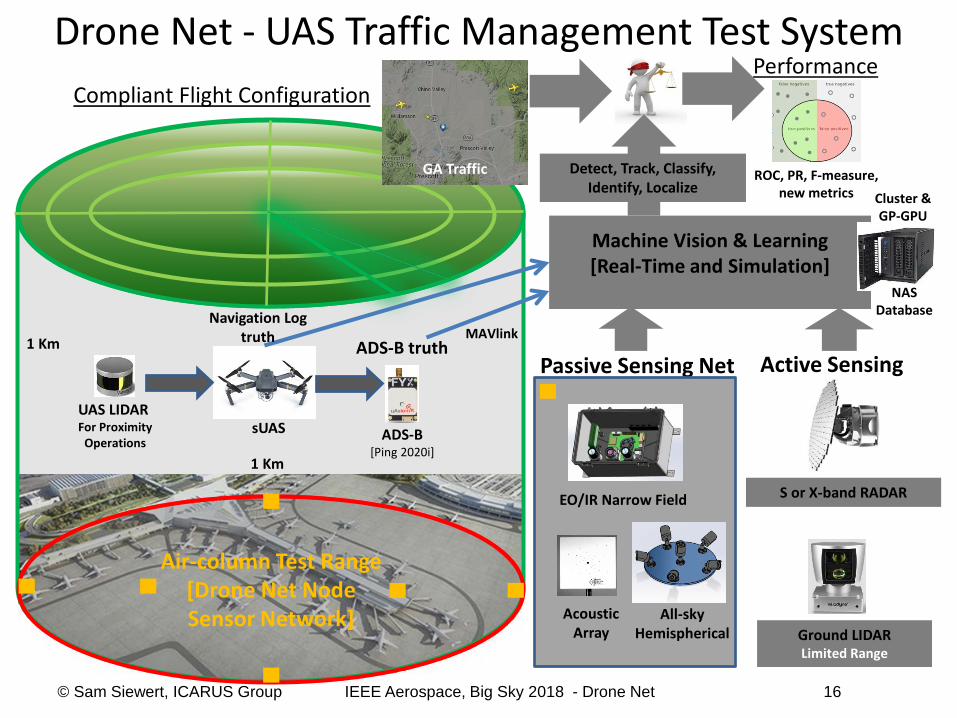
Drone Net - UAS Traffic Management Test System
Air-column Test Range [Drone Net Node Sensor Network]
1 Km
1 Km
ADS-B [Ping 2020i]
ADS-B truth
Machine Vision & Learning [Real-Time and Simulation]
sUAS
Compliant Flight Configuration
Passive Sensing Net
Acoustic Array
EO/IR Narrow Field
Performance
ROC, PR, F-measure, new metrics
S or X-band RADAR
Active Sensing
Ground LIDAR Limited Range
Detect, Track, Classify, Identify, Localize
Cluster & GP-GPU
GA Traffic
MAVlink
UAS LIDAR For Proximity
Operations
NAS Database
All-sky Hemispherical
Navigation Log truth
© Sam Siewert, ICARUS Group IEEE Aerospace, Big Sky 2018 - Drone Net 16

System Interconnection Schematic
© Sam Siewert IEEE Aerospace, Big Sky 2018 - Drone Net 17

GPS
DSRC Wireless
Access Point
Non-compliant sUAS
All-sky Hemispherical
Local Drone Net Machine Learning Server
Drone Net Master DBMS
Acoustic array
ADS-B Tx/Rx Compliant sUAS
LIDAR
EO/IR with IMU
EO/IR with IMU
All-sky Hemispherical
Acoustic array
EO/IR with IMU
ADS-B Rx ADS-B Rx
Drone Net - Flight/Ground Elements
© Sam Siewert, ICARUS Group IEEE Aerospace, Big Sky 2018 - Drone Net 18

617.5 meters [diagonal measure of cell that is 437m2]
Mavic Pro [335mm diagonal size]
FreeFly ALTA6 [1.126 m diameter]
Drone Net - Feasibility Test Range
© Sam Siewert, ICARUS Group IEEE Aerospace, Big Sky 2018 - Drone Net 19
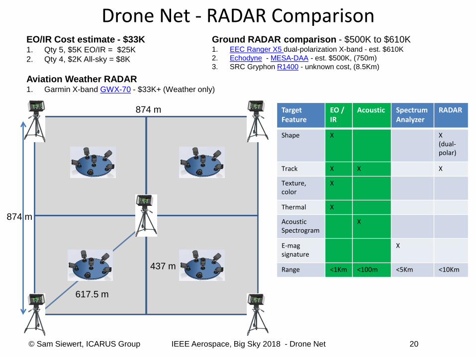
874 m
874 m
EO/IR Cost estimate - $33K 1. Qty 5, $5K EO/IR = $25K 2. Qty 4, $2K All-sky = $8K
Aviation Weather RADAR 1. Garmin X-band GWX-70 - $33K+ (Weather only)
Ground RADAR comparison - $500K to $610K 1. EEC Ranger X5 dual-polarization X-band - est. $610K 2. Echodyne - MESA-DAA - est. $500K, (750m) 3. SRC Gryphon R1400 - unknown cost, (8.5Km)
Target Feature
EO / IR
Acoustic Spectrum Analyzer
RADAR
Shape X X (dual-polar)
Track X X X
Texture, color
X
Thermal X
Acoustic Spectrogram
X
E-mag signature
X
Range <1Km <100m <5Km <10Km
Drone Net - RADAR Comparison
© Sam Siewert, ICARUS Group IEEE Aerospace, Big Sky 2018 - Drone Net 20
617.5 m
437 m

© Sam Siewert, ICARUS Group IEEE Aerospace, Big Sky 2018 - Drone Net 21
Cover ERAU Campus 5 EO/IR Nodes 4 All-sky Cameras Acoustic (TBD) 874m x 874m Approximately 1Km Grid Imagined for ATC VLOS from Physics to DLC Parking lot VLOS from AXFAB to DLC Parking lot
300m
300m

http://www.vision-doctor.com/en/optical-calculations https://www.nikonians.org/reviews/fov-tables
66 degree - 18mm lens [B=24mm, f’=18mm, g=617.5m] G=24mm * (617500mm - 18mm)/18mm G=823.31 meters 823.31 meters / 6000 pixels = 137.22 mm/ pixel 4.5 degree - 300mm lens [Nikon DX, APS-C] G=B * (g-f’) / f’ G=24mm * (617500mm - 300mm)/300mm G=49.38 meters 6000 pixels x 4000 pixels 49.38 meters / 6000 pixels = 8.23 mm / pixel
16.67x
Nikon DX DSLR Test Images 18mm [23%]
300mm [23%]
304%
80%
© Sam Siewert, ICARUS Group IEEE Aerospace, Big Sky 2018 - Drone Net 22
1x