SDT SERIES USER MANUAL - GoodWe
12
340-00352-00-PC Note: The information above is subject to change without prior motice, details refer to www.goodwe.com SDT SERIES USER MANUAL SOLAR INVERTER GoodWe (Germany) Fürstenrieder Str. 279a 81377 München, Germany T: +49 8974120210 +49 421 83570-170 (service) [email protected] [email protected] GoodWe (Brazil) Rua Abelardo 45, Recife/PE, 52050-310 T: +55 81 991239286 [email protected] [email protected] GoodWe (Netherlands) Franciscusdreef 42C, 3565AC Utrecht, the Netherlands T: +31 (0) 30 737 1140 [email protected] [email protected] GoodWe (UK) 6 Dunhams Court, Dunhams Lane, Letchworth Garden City, SG6 1WB UK T:+ 44 (0) 333 358 3184 [email protected] / [email protected] GoodWe (India) 1202, G-Square Business Park, Sector 30A, Opp. Sanpada Railway Stn., Vashi, Navi Mumbai- 400703 T: +91 (0) 2249746788 [email protected] / [email protected] GoodWe (Italy) Via Cesare Braico 61, 72100 Brindisi, Italy T: +39 338 879 38 81; +39 831 162 35 52 [email protected] (sales) [email protected]; [email protected] (service) GoodWe (Turkey) Adalet Mah. Megapol Tower K: 9 No: 110 Bayraklı - Izmir T: +90 (232) 935 68 18 [email protected] [email protected] GoodWe (Australia) Level 14, 380 St. Kilda Road, Melbourne, Victoria, 3004, Australia T: +61 (0) 3 9918 3905 [email protected] / [email protected] GoodWe (Mexico) Oswaldo Sanchez Norte 3615, Col. Hidalgo, Monterrey, Nuevo Leon, Mexico, C.P. 64290 T: +52 1 81 2871 2871 [email protected] / [email protected] GoodWe (Korea) 8F Invest Korea Plaza, 7 Heoleung-ro Seocho-gu Seoul Korea (06792) T: 82 (2) 3497 1066 [email protected] / [email protected] GoodWe (China) No. 90 Zijin Rd., New District, Suzhou, 215011, China T: +86 (0) 512 6958 2201 [email protected] (sales) [email protected] (service) SEMS Portal APP SolarGo APP SEMS Portal website www.semsportal.com LinkedIn Sitio web ofical
Transcript of SDT SERIES USER MANUAL - GoodWe

340-
0035
2-00
-PC
Note: The information above is subject to change without prior motice, details refer to www.goodwe.com
SDT SERIES USER MANUAL
SOLAR INVERTER
GoodWe (Germany)
Fürstenrieder Str. 279a 81377 München, GermanyT: +49 8974120210 +49 421 83570-170 (service)[email protected]@goodwe.com
GoodWe (Brazil)
Rua Abelardo 45, Recife/PE, 52050-310T: +55 81 [email protected]@goodwe.com
GoodWe (Netherlands)
Franciscusdreef 42C, 3565AC Utrecht, the NetherlandsT: +31 (0) 30 737 [email protected]@goodwe.com
GoodWe (UK)
6 Dunhams Court, Dunhams Lane, LetchworthGarden City, SG6 1WB UKT:+ 44 (0) 333 358 [email protected] / [email protected]
GoodWe (India)
1202, G-Square Business Park, Sector 30A, Opp. SanpadaRailway Stn., Vashi, Navi Mumbai- 400703T: +91 (0) [email protected] / [email protected]
GoodWe (Italy)
Via Cesare Braico 61, 72100 Brindisi, ItalyT: +39 338 879 38 81; +39 831 162 35 [email protected] (sales)[email protected]; [email protected] (service)
GoodWe (Turkey)
Adalet Mah. Megapol Tower K: 9 No: 110 Bayraklı - IzmirT: +90 (232) 935 68 [email protected]@goodwe.com.tr
GoodWe (Australia)
Level 14, 380 St. Kilda Road, Melbourne,Victoria, 3004, AustraliaT: +61 (0) 3 9918 [email protected] / [email protected]
GoodWe (Mexico)
Oswaldo Sanchez Norte 3615, Col. Hidalgo, Monterrey,Nuevo Leon, Mexico, C.P. 64290T: +52 1 81 2871 [email protected] / [email protected]
GoodWe (Korea)
8F Invest Korea Plaza, 7 Heoleung-roSeocho-gu Seoul Korea (06792)T: 82 (2) 3497 [email protected] / [email protected]
GoodWe (China)
No. 90 Zijin Rd., New District, Suzhou, 215011, ChinaT: +86 (0) 512 6958 [email protected] (sales)[email protected] (service)
SEMS Portal APPSolarGo APP SEMS Portal websitewww.semsportal.com
LinkedIn Sitio web ofical

02
02
02
03
05
3 Installation3.1 Mounting instruction
3.2 Inverter Overview and Package
3.3 Inverter Installation
3.4 Electrical Connection
11
11
12
16
16
16
4 System Operation4.1 Indicator Lights
4.2 User Interface and Use of the Display
4.3 Error message
4.4 Wi-Fi Reset & Wi-Fi Reload
4.5 Special Adjustable Setpoints
175 Troubleshooting
186 Technical Parameters
207 Certificates
208 Maintenance
012 Safety measures
011 Symbols

SDT4~6KW
8
Risk of injury due to improperhandling of the device Recyclable naterials
Danger of high voltage & electric shock Keep upward
Don't touch, hot surface! Stack no more than 8
Special disposal instructions Fragile
Refer to operation instructions
Wait at least 5 minutes after disconnecting the inverter before touching internal parts
Keep Dry
CE mark.
2 Safety measures
1 Symbols
The SDT series inverter of Jiangsu GoodWe Power Technolgy Co., Ltd. (hereinafter referred to as GoodWe) strictly conforms to related safety rules in design and test. Safety regulation relevant to the location shall be followed during installation, commission-ing, operation and maintenance. Improper operation may have a risk of electric shock or damage to equipment and property.(SDT: Dual-MPPT, Three - Phase.)• Installation, maintenance and connection of inverters must be performed by qualified personnel, in commpliance with local
electrical standards,regulations and the requirements of local power authorites and/or companies.• To avoid electric shock, DC input and AC output of the inverter must be disconnected .Wait at least 5 minutes before performing
any installation or maintenance.• The temperature of some parts of the inverter may exceed 60℃ during operation. To avoid being burnt, do not touch the inverter
during operation. Let it cool before touching it.• Keep children away from inverter.• Do not open the front cover of the inverter. Apart from performing work at the wiring terminal (as instructed in this manual),
touching or changing components without authorization may cause injury to people, damage to inverters and annulment of the warranty.
• Static electricity may damage electronic components. Appropriate methods must be adopted to prevent such damage to the inverter, otherwise may cause damage to inverters and annulment of the warranty.
• Ensure that the output voltage of the proposed PV array is lower than the maximum rated input voltage of the inverter; otherwise the inverter may be damaged and the warranty will be annulled.
• When exposed to sunlight, the PV array will generate dangerous high DC voltage.Please operate according to our instructions, or it will result in danger to life.
• PV modules should have an IEC61730 class A rating.
• If the equipment is used in a manner not specified by the manufacturer, the protection provided by the equipment will be impaired.
• Te way to completely isolate the equipment: switch off the DC switch, disconnect the DC terminal, and disconnect the AC terminal or AC breaker.
• Do not insert or pull the AC or DC terminals when the inverter is electrified.• If there are more than 3 PV strings on input side, an additional fuse installationwill be suggested.• An earthing photovoltaic system needs to be connected with an Arc fault detecotr on DC side.• The inverter can exclude the possibility of DC residual currents to 6mA in the system, where an external RCD is required in addition
to the built-in RCMU, type A RCD must be used to avoid tripping.• The PV is not grounded as default configuration.
To ensure IP65, inverters must be sealed well.Please install the inverters in one day after unpacking. Otherwise please seal all unused terminals/holes.Not allowed to keep any terminals/holes open,.Please confirm there is no risk to have water&dust in.
3 Installation3.1 Mounting Instruction• In order to achieve optimal performance, the ambient temperature should be lower than 45℃.• For the convenience maintenance activities, please install the inverter at eye level.• Inverters should NOT be installed near flammable and explosive items. Any strong electromag-
netic should be kept away from installation site.• Product lable and warning symbol shall be read clearly after installation.• Please install inverter in the place where is not exposed to direct sunlight, rain and snow.
3.2 Inverter Overview and PackageCheck if the scope of delivery is complete and if there is any visible damage.
3.2.1 Inverter OverviewPlease refer to Figure3.2.1-1 for SDT4~6KW.Please Refer to Figure3.2.1-2 for SDT8~15KW.
1. PV input terminals
2. DC Switch (Optional)
3. Com Module
4. AC output terminal
5. Indicator lights
6. Button
Figure 3.2.1-1
COM
COM
0201
Accmulated snowKeep away from sunlight Keep dry Keep it clear of snow Sun Rain
4321
5
6

Max15°
3.3 Inverter Installation3.3.1 Selecting the installation locationThe following must be considered when selecting the best location for an inverter:• The mount and installation method must be appropriate for the inverter's weight and
dimensions.• The location must be well ventilated and sheltered from direct sunlight.• The inverter must be installed vertically or with a backward tilt less than 15℃.No sideways tilt is
allowed. The connection area must point downwards. Refer to Figure 3.3.1-1.
3.3.2 Mounting Procedure(1) Use the wall-mounted bracket as a template and drill holes in the wall, 10 mm in diameter and
80mm deep. Please referred Figure 3.3.2-1.(2) Fix the wall-mounted bracket on the wall by using the expansion bolts in the accessories bag.(3) Hold the inverter by the side groove as Figure 3.3.2-2.(4) Install the inverter on the wall-mounted bracket. Please refer to Figure 3.3.2-3.
For dissipation of heat and convenience of dismantling, clearnaces around the inverter at least must met the standard as below :The installation position should not prevent access to the disconnection means.
1. PV input terminals(SDT12~15KW PV *3pair)
2. DC Switch (Optional)
3.2.2 Package
Figure 3.3.1-2
Figure 3.3.2-1
Figure 3.2.1-2
Figure 3.3.1-1
COM
COM
SDT8~15KW
6. Indicator lights7. Button
3. Com Module4. AC output terminal5. Fan
0403
200mm
100mm
45mm
UpwardDownwardFrontBoth sides
-------------300mm---------500mm
----------------300mm----------200mm
200mm 300mm200mm
500mm
500mm
Wall-mounted Bracket DC Plug
&
AC Connector Screw
PE Terminal
User's Guide ofSolarGo APP
Inverter
Com ModuleExpansion Bolts User ManualPin Terminal
SolarGo
Other certificatedInformation
Certificated
6
75
4321

3.4 Electrical Connection3.4.1 Connection to grid (AC side Connection)1. Check the grid voltage and frequency if it can comply with the required voltage and frequency
of inverter connection.2. Add breaker or fuse to AC side, the specification should be more than 1.25 times of rated AC
output current.3. The PE line of inverter should be connected the earth, make sure the impedance of neutral wire
and earth wire is less than 10ohm. 4. Disconnect the breaker or fuse between the inverter and the utility.5. Connect the inverter to the gird as follows: There are two AC connector brands for inverter,
VACONN AND Exceedconn. Please refer to Figure 3.4.1-1.6. The AC line construction shall be such that if the cord should slip in its anchorage, placing a
strain on condutors, the protective earthing conductor will be the last to take the strain,such as the PE line is longger than L and N.
Note: Multiple inverters are not allowed to share a circuit breaker.The integrated leakage current detection device of the inverter can detect external leakage current in real time. When the detected leakage current exceeds the limit value, inverter will quickly disconnect with the grid, If the leakage current protection device is installed externally, the action current should be 300mA or higher.
* Neutral conductor shall be blue, line conductor shall be black or brown(preferred,protective earth bonding line shall be yellow-green.
* Fix(moment:0.6N.m)the connector of AC cable to the corresponding terminals.
3.4.2 AC circuit breaker and leakage current protection device In order to ensure that the inverter can be safely and reliably disconnected from the power grid, please install an independent two pole circuit breaker to protect the inverter.
Please refer to figure 3.4.1-2 for installation instruction of VACONN series.
Please refer to Figure 3.4.1-4 for cable specification of AC side .
VACONN Series Exceedconn Series
Figure 3.3.2-2 Figure 3.3.2-3
Figure 3.4.1-1
Figure 3.4.1-2
Recommended circuit breaker specifications
16A
25A
32A
Inverter model
GW4KL-DT / GW5KL-DT / GW6KL-DTGW4K-DT / GW5K-DT / GW6K-DT
GW8K-DT / GW10K-DT
GW12K-DT / GW15K-DT
Figure 3.4.1-4
0605
Annealed copper wire
A B CGrade
A
B
C
Description
O.D.
Conductor Material Sectional Area
Bare Wire Length
Value
10~12mm
2.5~6mm2
10mm around
fasten screw cap clockwise fasten screw cap clockwise10mm
Inverter
Fastening three screws toensure each screw head isnot exceeding the surface
Material (Annealed copper wire)Pin1 ------ R phasePin2 ------ S phasePinL ------ T phasePinN ------ T phasePinPE ----- PE phase
Please refer to figure 3.4.1-3 for installation instruction of Exceedconn series.
Figure 3.4.1-3
7-9mm
Torque 0.7~0.9N.m
unlock
lock
When unplugging the AC terminals, press the
button and hold it to unlock
Make sure the terminal is rotated to the lock position before the inverter is started

DC Cable specification is showed as Figure 3.4.2-2.
DC Cable should use dedicated PV cable(Suggest using 4mm PV1-F wire).
Please refer to Figure 3.4.3-3 for installation instruction of DC connector .
3.4.4 Earth Terminal Connection
The earth terminal should be added accord-ing to the requirement of EN 50178. It is neces-sary that installation person must connect the terminal to earthing wire.
The earth connecting terminal is on the side of inverter, illustrated as Figure 3.4.4-1. The customer should select the right place to grounding based on site condition.
3.4.5 Wi-Fi CommunicationThe Wi-Fi communication function is only applied to WiFi module.The detailed configuration instruction can refer to Wi-Fi Configuration in the accessory box.After configuration, please browse http://www.goodwe-power.com to create PV station.
Figure 3.4.3-1
Figure 3.4.4-1
Figure 3.4.3-2
Figure 3.4.3-4Special tools are used to stitching.
MC4 series & QC4.10 series DEVALAN series & AMPHENOL series
Limit buckle can notcrimping the wire
Negative connector
Positive connector
DEVALAN SERIES MC4 SERIES
AMPHENOL SERIES QC4.10 SERIES
There are four types of DC connectors, DEVALAN, SUNCLIX/MC4, AMPHENDL H4 and QC4.10 series. Please refer to Figure 3.4.3-1.
0807
Grade
A
B
C
Description
O.D.
Conductor Material Sectional Area
Bare Wire Length
Value
4~5mm
2.5~4mm2
7mm around
A B
C
3.4.3 DC Side Connection1. Before connecting the PV strings, please ensure the plug connectors have the correct polarity.
Incorrect polarity could permanently damage the unit. 2. The open circuit voltage of the PV strings cannot exceed the maximum input voltage of the
inverter.3. Only DC connectors provided by us are permitted to use.4. The positive and negative pole is forbid to connect PE wire(Ground wire).Otherwise, it will
damage the unit.5. Don't connect positive or negative pole of PV string to PE wire. Otherwise , it will cause damage
to inverter.6. Positive cable shall be red, negative cable shall be black.7. The minimum insulation resistance to ground of the PV panels for SDT series must exceed 33.4K
Ω(R=1000/30mA).There is a risk of shock hazard if the requirements of minimum resistance are not met.
3.4.7 DRED / Remote shutdown / Meter connection
DRED(demand response enabling device) is only for Australian and New Zealand installations, in compliance with Australian and New Zealand safety requirements. And DRED is not provided by GoodWe.
Remote shutdown is only for Europe installations, in compliance with Europe safety require-ments. And Remote shutdown device is not provided by GoodWe.
Detailed operation is shown as below:
10
COM
COM
COM
COM
6.5mm
25mm
3.4.6 SMART METER & CT connection diagramPlease refer to Figure 3.4.6-1 for connection methods of Smart Meter and CT.
Step 1:Plug out the terminal and dismantle the resistor / short wire on it, if you want use the DRED and Remote shutdown function.Note:
DRED should be connected through " 6-pin COM port" as the figure shows.
Remote Shutdown device should be connected through " 2-pin COM port" as the figure shows.
Step 2-1 For DRED:Put the cable through the plate.
3.4.7 Earth Fault AlarmThe inverter complies with IEC62109-2 chapter 13.9. When earth fault occurs, the fault indicator LED on the front cover will light up. For none wifi inverter, the buzzer in inverter will keep ringing 1 minute and ring again after half an hour unless the fault is resolved (This function is only available for Australia/New Zealand).
Tightening the screws and thescrews are not over the surface
CablesThe insulator
Screw cap
Single hole seal ring6-Pin terminal
Step 3:Connect the terminal to the right position onto the inverter.
FunctionDRM1/5DRM2/6DRM3/7DRM4/8REFGen
Com/DRM0
NO.123456
6.5mm
25mm
Step 2-2 For Remote shutdown:Put the cable through the plate.
Tightening the screws and thescrews are not over the surface
CablesThe insulator
Screw cap
Single hole seal ring2-Pin terminal
FunctionDRM4/8REFGen
NO.12
6.5mm
25mm
Step 2-3 For Meter:Put the cable through the plate.
Tightening the screws and thescrews are not over the surface
CablesThe insulator
Screw cap
Single hole seal ring2-Pin terminal
FunctionMeter +Meter -
NO.12
Remote shutdown(optional)
DRED(optional)
Figure 3.4.6-1
CT A connect to L1
CT B connect to L2
CT C connect to L3
Power Meter
PV
Inverter
“To Smart Meter”
Loads
Grid
PENL3L2L1
Grid
House→Grid
Smart M
eter
N
L
Reset
SMART METER
US
B
METERMETER
DRED Remote shutdown
09

2. Display areaLine 1---Working status information
This area displays the status information. "Waiting Pac=0.0W" indicates the inverter is standing by for power generation; "Checking**S Pac=0.0W" (checking time is based on safety, and varies from country to country) indicates the inverter is self-checking, counting down and preparing for power generation. "Normal Pac=6000.0W" indicates the inverter is generating power. If any condition of the system is abnormal, the screen will display an error message. Refer to Table 4.3.
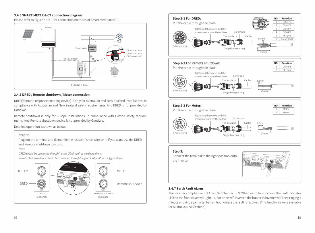
Through key operation, the screen can display different information such as operation parame-ters and power generation status in this area. There are two levels of menus, and the flow chart of first level menu is shown as the diagram.
3. Use of the displayThere are 2 modes of button operation: short press and long press.
4. Use of the display and LCD display
The display allows accessing the configuration of the basic parameters. All the language, All the language, time and country setting can be configured by buttons. The menu, shown in the LCD display area has two levels of menu. Short and long key presses will take you to different menus and through each menu. Items in the first level menu will be locked if the second level menu doesn't show. For these items, when the key is pressed for two second, the LCD will display the word "Lock" followed by data relating to the first level menu item. The locked menu can only be unlocked under system mode switching, fault occurrence or key operation.
In all levels of menu, if no action is taken for 20 seconds, the backlight of the LCD display will be switched off, and the display will automatically revert to the first item of the first level menu, and then any modifications made to the data will be stored into internal memory.
4.2 User interface and use of the displaySet Safety Country:If display shows "GW6K-DT Pac=6000.0W", then long press (2S) the key to enter the second level menu. Short press to browse the safety country available. Please wait for 10s after choosing the suitable safety country ,then display will show "setting..." and jump to "Set OK" or "Set Fail".
1. A schematic of the display screen is shown as below:
Display area is divided as follows:
4 System Operation4.1 Indicator Lights
NormalPac=6000.0W
Line 1Line 2
Inverter with LCD, indicator lights in Yellow/Green/Red correspondently refer to
ON = WiFi CONNECTED / ACTIVEBLINK 1 = WiFi SYSTEM RESETTINGBLINK 2 = WiFi ROUTER PROBLEMBLINK 4 = WiFi SERVER PROBLEMOFF = WiFi NOT ACTIVEON = INVER TER IS FEEDING POWEROFF= INVER TER IS NOT FEEDING POWERATTHE MOMENTON = FAULT OCCURREDOFF = NO FAULT
POWER
RUN
FAULT
1211
For inverters without LCD, indicator lights in Green/Green/Green/Red correspondently refer to
ON = EQUIPMENT POWER-ONOFF= EQUIPMENT POWER-OFFON = INVERTER IS FEEDING POWEROFF= INVERTER IS NOT FEEDING POWESINGLE SLOW FLASH = SELF CHECK BEFORE GRID CONNECTSINGLE FALSH = WILL CONNECT WITH GRIDON = WiFi CONNECTED / ACTIVEBLINK 1 = WIRELESS SYSTEM RESETTINGBLINK 2 = WIRELESS ROUTRE PROBLEMBLINK 4 = WIRELESS SERVER PROBLEMOFF = WIRELESS NOT ACTIVEON = FAULT OCCURREDOFF = NO FAULTFAULT
RUN
POWER
SEMS
5. Menu Introduction• When the PV panel is feeding power to the inverter, the screen will show the first-level menu.• The initial display is the the first item of the first level menu, and the interface displays the
current status of the system, It shows "Waiting Pac=0.0W" in the initial state; it shows "Normal Pac=6000.0W" during power generation mode; if there is something wrong with the system, an error message is shown. Please refer to chapter 5.The way to view PV voltage, PV current, grid voltage, current and frequency:
• Short press the key to enter the E-Today menu which displays the total power generation for today.
• Short press the key to enter the E-Total menu which displays the total power generation up to today.
• Short press the key to enter the Vpv menu which displays the PV voltage in "V".• Short press the key to enter the Ipv menu which display sthe PV current in "A".• Short press the key to enter the Vac menu which displays the grid voltage in "V".• Short press the key once more to enter the Iav menu which displays the grid current in "A".• Short press the key once more to enter the Frequency menu which displays the grid frequen-
cy in HZ.• View Error massage
Short press the key once more to enter the Error Massage History menu.Long press (2s) the key to enter the second level menu of error detection. The last three inverter error massage will be shown by short pressing the key in this second level menu. The records include error massage and error times (190520 15:30). Error massage can be found in Table 4.3.
• The way to view model name and reconfigure safety country:From the error massage history item in the first level menu, short press the key once to see model name.If you want to change the safety country, please hold the key for 2 seconds, then the LCD screen will go to the second level menu.In the second level menu, short press the key can change the safety country. If you change nothing in second level menu and without pressing button in 20 seconds ,then the backlight of LCD will power off and return to the first level menu. If you change the safety country ,the LCD screen will show: "Setting..." after 10 seconds then show : "Set Fail" or "Set OK".
• View software versionFrom the model name item in the first level menu, short press the key once to see software version.The current software version can be shown in this menu.Setting:
• Set language:Short press the button to enter the Set Language menu. Long press(2s)the key to enter the second level menu. Short press to browse the available languages. If you change nothing in second level menu and without pressing button in 20 seconds , then the backlight of LCD will power off and screen return to the first level menu. If you change the Language,the LCD screen will show:"Setting..." after 10 seconds then show :
1413
50Hz GridDefault
Lock
No Error
Utility Loss190520 05 :21
50Hz GridDefault
Language
Portuguese
Ipv= 4.1/ 4.1APac=6000W
Vpv=325.5/325.5VPac=6000W
E-Total=533.17KWhPac=6000W
E-Today= 15.2KWhPac=6000W
NormalPac=6000W
First Level menu
Short press
Short press
Short press
Short press
Short press
Error HistoryPac=6000W
GW 6K-DTPac=6000W
Ver :V 1.XX .XX .XX
Set LanguagePac=2595.5W
Set TimePac=6000W
WiFi ResetPac=6000W
Short press
Short press
Short press
Short press
Short press
Short press
WIFI
WiFi ReloadPac=6000W
Long press 2SSecond Level menu
Long press 2S
Long press 2S
Long press 2S Short press forsafety country select
Long press 2S
Short press
Short press
2000-00-00 00 :00
2000-00-00 00 :00
���
2000-00-00 00 :00
Short press to setThe second numberLong press 2S
Long press 2S
Long press 2S
Long press 2S
Long press 2S
Short press to setThe third number
Short press to setThe last number
WiFi Resetting
Long press 2S
WiFi Reset OK
WiFi Reset Fail
Wait 25s
WiFi Reloading
Long press 2S
WiFi Reload OK
WiFi Reload Fail
Wait 25s
PF AdjustPac=6000W
Short press
Short press
Shadow MPPT OFFPac=6000W
Shadow MPPT ONPac =6000W
Power Limit OFFPac=6000W
Power Limit ONPac =6000W
Set Power LimitXXX %
Set Modbus AddrPac =6000W
Disable
lagging 0.95
lagging 0.95
lagging 0.95
Short press to select Leading Or lagging
Long press 2S
Long press 2S Long press 2SShort press to select
Number 8 or 9
Short press to selectNumber 0~9
Set Power LimitXXX %
Set Power LimitX XX %
Set Power LimitXX X%
Long press 2S
Long press 2S Long press 2S
Long press 2S
Short press Short press
Set Addr :XXX
Set Addr :X XX
Set Addr :XX X
Long press 2S
Long press 2S Long press 2S
Short press to selectNumber 0~9
Short press to selectNumber 0~9
Short press to selectNumber 0 or 1
Short press to selectNumber 0~2
Short press to selectNumber 0~9
Short press to selectNumber 0~9
Short press
OrLong press 2S
Short pressShort press
OrLong press 2S
Short press
Short press
Long press 2S
Set time
Set MOBUS adress
Vac =230/230/230V
Iac=11.1/11.1/11.1A
Fac=50.02HZ
Short press
Short press
Wait 10s Set OK
Set FailWait 10s
Wait 10s
Wait 10s
Wait 10s
Wait 10s
Wait 10s
Wait 10s
Wait 10s
Wait 10s
Wait 10s
Wait 10s
Wait 10s
Wait 10s
Wait 10s
LVRT ONPac =6000W
Short press
Long press 2S
Set OK
Set Fail
LVRT OFFPac =6000WLong press 2S
Or
Setting ...
Setting ...
Setting ...
Setting ...
Set OK
Set Fail
Setting ...
Set OK
Set Fail
Set OK
Set Fail
Set OK
Set Fail
Setting ...
Wait 10s
RSSI : 0% Pac=6000W
Grid TypePac =6000W Delta Grid
Star Grid
Set OK
Set Fail
Setting ...
Short pressLong press 2S
Short press
Wait 10s
Wait 10sLong press 2S to set password,the default password is "1111"
Pac=6000W

Note:
If the power limiting function is ON, the maximum output power of the inverter will be limited at the power limiting
setting value while the inverter is without the power limmiting device
4.4 Wi-Fi Reset & Wi-Fi ReloadThe two functions are only available for Wi-Fi model inverters.
Wi-Fi reload function is used to change the Wi-Fi configuration to default value.
Please configure the Wi-Fi again as 3.4.5 after using the function.
Press the key until the LCD displays "Wi-Fi Reload", then long press (2S) until the LCD displays "Wi-Fi Resetting...". Stop pressing and wait for the screen showing "Wi-Fi Reset OK" or "Wi-Fi Reset Failed".
Press the key until the LCD displays "Wi-Fi Reload", then long press (2S) until the LCD displays "Wi-Fi Reloading...". Stop pressing and wait for the screen showing "Wi-Fi Reloading OK" or "Wi-Fi Reloading Failed".
4.5 Special Adjustable SetpointsThe inverter has a field where the user could set functions, such as trip point, trip time, time of reconnection, active and invalid of QU curve and PU curve. Fuctions can be adjusted through special software. If insterested, please contact After-Sales. The software instructions are available on the offical website. Alternatively, please contact after-sales for more information.
4.3 Error messageAn error message will be displayed on the LCD if a fault occurs.
Error messFac FailIsolation FailVac FailPV Over VoltageOver TemperatureUtility Loss
DescriptionGrid frequency out of pemissible range.Grund insulation impedance is too low.Grid voltage out of permissible range.Overvoltage at DC input.Over temperature on the case.Utility is unavailable.
Long press 2S
Long press 2SLong press 2S
Long press 2S
Long press 2S Set Power LimitXXX %
Short press to selectNumber 0 or 1
Short press to selectNumber 0~9
Short press to selectNumber 0~9
Short press
Or
Short pressShort press
Or
Short press
Short press
Set OK
Set Fail
Wait 10s
Wait 10s
Wait 10s
Setting...
PF AdjustPac = 6000W
Shadow MPPT OFFPac = 6000W
Power Limit OFFPac = 6000W
Power Limit ONPac = 6000W
Set Power LimitXXX %
Shadow MPPT ONPac = 6000W
Set Power LimitXXX %
Set Power LimitXXX %
Long press 2S
1615
(such as a CT/Meter) or the power limiting device is out of work.You need to enter a password before setting up power limit . The default password is "1111".(only for Australian security regulations)
"Set OK" or "Set Fail".• Set time:
From the first level Set language menu, short press the key to enter the Set Time menu.Long press(2s)the key to enter the second level menu. The initial display is "2019-00-00 00:00", in which the first four numbers represents the year (e.g 2000-2099); the fifth and sixth number represent the month (e.g 01-12); the seventh and the eighth numbers represent the data(e.g 01-31). The remaining number represents the time.Short press to increase the number in current location, and long press to move the cursor to next position. The inverter will store the time after 20 seconds if there's no key operation, and the LCD will automatically return to the main menu and the backlight will switch off.
• Set protocol:The function is only opened for service personnel, set wrong protocol could lead to commu-nication failure.From the first level Set Time menu, short press the key once to enter protocol display menu. Press the Key for 2s to enter submenu. The circulatory submenu including two protocols can be found. The protocol can be chosen by short pressing the key. The inverter will store the chosen protocol without any action within 10s and LCD display will automatically return to main menu when the backlight is off.
• MPPT function for Shadow:The default setting for shadow optimizer is disabled.Please do not enable the function when there's no shadow on panel. Otherwise it could lead to generate less power.Press the key to enter Shadow Optimize menu. When it shows "Shadow MPPT OFF", it means the shadow optimizer is on. Press the key for 2s to disable the function.
6. Power limiting function settingThe Operations that the ON/OFF of power limiting function (the default is OFF) and the power limiting settings (the default is 2% rated) are shown below:
(7) Operation of Display when commissioning.When the input voltage reaches the inverter turn-on voltage, the LCD starts to work, the yellow light is on and the LCD displays "Waiting". More information will be displayed within a few second. If the inverter is connected to the grid, "Checking XXs" will be displayed and a count-down will commence from 30 seconds. When it shows "00S", you will hear the relay triggered 4 times. ThenThe LCD will display "Normal". The instant power output will be shown at the left bottom of the LCD.

6 Technical Parameters5 TroubleshootingIn most situations, the inverter requires few maintenance. However, if the inverter is not working properly, please try the following troubleshooting solutions;• When a problem occurs, the red (fault) LED indicator on the front panel will light up and the LCD
screen will display the type of the fault.The following table lists error messages and the solutions for associated faults.
Note: When sunlight is insufficient, the PV inverter may continuously start up and shut down automati-cally due to insufficient power generated by the PV panels, which would not lead to inverter damage. If the problem still exists, please call the local service office.
1. Disconnect DC switch, take off DC connector.Check the impedance between PV (+) & PV (-) to earth.2. If impedance is less than 100KΩ, please check the insulation of PV string wiring to the earth.3. If impedance is larger than 100KΩ, please contact local service office.4. Take off AC connector, measure the impedance between neutral and PE. If it is larger than 10 KΩ,
please check AV wiring.
1. Disconnect the DC switch, take off AC connector, and then measure the voltage between line and neutral no connector. Check if it conforms to the grid-connected specification of inverter.2. If not, please check if the distribution switch is connected and the grid is normal.3. If conforming to the specification, reconnect AC connector and DC connector. If the problem still exists, please call the local service office.
1. Disconnect the DC switch , take off DC connector,and then check PV string voltage. Check if it exceeds the input voltage in inverter specification.2. If it does, please reconfigurate PV panel string.3. If the problem still exists, please call the local service office.
1. Please check if the installation position conforms to the specification.2. Try to lower the surrounding temperature.3. Move the inverter to the vent or change the installation position.4. If the problem still exists, please call the local service office.
1. Disconnect the DC connector.2. Reconnect the DC connector.3. If the problem still exists, please call the local service office.
1. Disconnect the DC connector.2. Reconnect the DC connector.3. If the problem still exists, please call the local service office.
1. Disconnect the DC switch, take off DC connector, and then measure the voltage of PV string. 2. Plug in DC connector and reconnect DC switch.3. If the voltage is less than 70V, please check the PV string configuration.4. If the voltage is higher than 125V and still no display, please contact local service office.
1. Disconnect the DC switch, check the insulation of PV string wiring to earth.2. Reconnect the DC switch again.3. If the problem still exists, please call the local service office.
1. Disconnect DC switch, take off the AC connector, and then measure the voltage between line and neutral in connector. Check if it conforms to the grid-connected specification of inverter.2. If not, please check grid wiring.3. If conforming to the specification, please connect AC connector, reconnect DC switch.The inverter will connect grid automatically. If the probiem still exists, please call the local service office.
1.The PV inverter will automatically restart if the Fac returns to normal.2.If the problem still exists, please call the local service office.
Others No display
Vac Fail
Fac Fail
Display Troubleshooting
Ground I Fail
Isolation Fail
GFCI FailDC Bus HighSPI FailEEPROM R/W Fail
Relay-Check Fail
Over Temperature
PV Over Voltage
Utility Loss
Systemfailure
Systemfailure
Inverterfailure
DCI High
1817
~1 (Adjustable from 0.8 leading to 0.8 lagging)<3%
Technical DataPV Input DataMax. DC Power (W)Max. DC Input Voltage (V)[1]
MPPT Range (V)Starting Voltage (V)Max. Input Current (A)Max. Short Current (A)No. of MPP TrackersNo. of Input Strings per TrackerAC Output DataNominal Output Power (W)Max. Output Apparent Power (VA)Nominal Output Voltage (V)Nominal Ouput Frequency (Hz)Max. Output Current (A)Output Power FactorOutput THDi (@Nominal Output)EfficiencyMax. EfficiencyEurope EfficiencyProtectionAnti-islanding ProtectionInput Reverse Polarity ProtectionInsulation monitoringDC Surge ProtectioinAC Surge ProtectioinResidual Current Monitoring UnitAC Over Current ProtectionAC Short ProtectionAC Over Voltage ProtectionArc Fault Detection On PV Side Terminal Temperature DetectionGeneral DataOperating Temperature Range (℃)Relative HumidityOperating Altitude (m)CoolingUser InterfaceCommunicationWeight (kg)Size (Width*Height*Depth mm)Protection DegreeNight Self Consumption (W)TopologyCertifications & StandardsGrid RegulationSafety RegulationEMC
GW6K-DT
90001000
180~850160
12.5/12.515.6/15.6
21/1
60006600
400, 3L/N/PE50/60
9.6
98.2%>97.6%
IntegratedIntegratedIntegrated
Integrated(Type III)Integrated(Type III)
IntegratedIntegratedIntegratedIntegratedOptionalOptional
-30~600~100%≤4000
LED or LCD
IP65<1
Transformerless
GW5K-DT
75001000
180~850160
12.5/12.515.6/15.6
21/1
50005500
400, 3L/N/PE50/60
8
98.2%>97.6%
Natural Cooling
15354*433*147
GW5KL-DT
7500600
180~850160
12.5/12.515.6/15.6
21/1
50005500
400, 3L/N/PE50/60
8
98.0%>97.5%
GW4K-DT
60001000
180~850160
12.5/12.515.6/15.6
21/1
40004400
400, 3L/N/PE50/60
6.4
98.2%>97.6%
GW4KL-DT
6000600
180~550160
12.5/12.515.6/15.6
21/1
40004400
400, 3L/N/PE; 50/60
6.4
98.0%>97.5%
WiFi or LAN(Optional)
VDE-AR-N 4105,EN 50549/VDE0126-1-1,AS/NZS 4777.2,CEI-021,IEC61727IEC62109-1&2
EN 61000-6-1, EN 61000-6-2, EN 61000-6-3, EN 61000-6-4,EN 61000-4-16, EN 61000-4-18, EN 61000-4-29

IEC62109-1/-2 VDE-AR-N 4105
Moisture parameters
Temperature RangeHumidity Range
3K30~+40℃
5%~85%
4K2-33~+40℃
15%~100%
4K4H-20~+55℃4%~100%
Level
7 Certificates
8 Maintenance
VDE0126-1-1
EN50549 AS4777.2 IEC62116 IEC61727
Note:Overvoltage category definitionCategory I: applies to equipment connected to a circuit where measures have been taken to reduce transient
overvoltage to a low level.Category II: applies to equipment not permanently connected to the installation. For example, appliances,
portable tools and other plug-connected equipment;Category III: applies to fixed downstream equipment, including the main distribution board. For
example,switchgear and other equipment in an industrial installation;Category IV: applies to equipment permanently connected at the origin of an installation (upstream of the main
distribution board).For example, electricity meters, primary overcurrent protection equipment and other equipment connected directly to outdoor open lines.
Moisture location category definition
Environment category definitionOutdoor : the ambient air temperature is -20~50℃.Relative humidity range is from 4% to 100%, applied to PD3.Indoor unconditioned: the ambient air temperature is -20~50 ℃. Relative humidity range is from 5% to 95%,
applied to PD3.Indoor conditioned: the ambient air temperature is 0~40 ℃. Relative humidity range is from 5% to 85%, applied
to PD2.
Pollution degree definitionPollution degree 1: No pollution or only dry, non-conductive pollution occurs. The pollution has no influence.Pollution degree 2: Normally only non-conductive pollution occurs. However, a temporary conductivity
occasionally caused by condensation must be expected.Pollution degree 3: Conductive pollution occurs. Or dry, non-conductive pollution becomes conductive due to
condensation, which is expected.Pollution degree 4: Persistent conductive pollution occurs. For example, the pollution cause by conductive
dust, rain and snow.
Regular maintenance ensures a long operating life and optimal efficiency of the entire PV plant.
Caution: Before maintenance, please disconnect the AC breaker firstly and then disconnect DC breaker. Wait 5 minutes until the residual voltage has been drained.[1]Please make sure the voltage of PV string will not exceed the Max. DC voltage.
2019
GW12KT-DT
180001000
180~850160
12.5/2515.6/31.2
21/2
1200014000
400, 3L/N/PE50/6020.3
98.3%>97.7%
Fan Cooling
18354*433*155
GW15KT-DT
225001000
180~850160
12.5/2515.6/31.2
21/2
1500016500
400, 3L/N/PE50/60
24
98.3%>97.7%
Fan Cooling
18354*433*155
GW10KT-DT
150001000
180~850160
12.5/12.515.6/15.6
21/1
1000011000
400, 3L/N/PE50/60
16
98.3%>97.7%
IntegratedIntegratedIntegrated
Integrated(Type III)Integrated(Type III)
IntegratedIntegratedIntegratedIntegratedOptionalOptional
-30~600~100%≤4000
Fan Cooling
LED or LCD16
354*433*155IP65<1
Transformerless
GW8K-DT
120001000
180~850160
12.5/12.515.6/15.6
21/1
80008800
400, 3L/N/PE50/6012.8
98.2%>97.6%
Fan Cooling
16354*433*155
~1 (Adjustable from 0.8 leading to 0.8 lagging)<3%
Technical DataPV Input DataMax. DC Power (W)Max. DC Input Voltage (V)[1]
MPPT Range (V)Starting Voltage (V)Max. Input Current (A)Max. Short Current (A)No. of MPP TrackersNo. of Input Strings per TrackerAC Output DataNominal Output Power (W)Max. Output Apparent Power (VA)Nominal Output Voltage (V)Nominal Ouput Frequency (Hz)Max. Output Current (A)Output Power FactorOutput THDi (@Nominal Output)EfficiencyMax. EfficiencyEurope EfficiencyProtectionAnti-islanding ProtectionInput Reverse Polarity ProtectionInsulation monitoringDC Surge ProtectioinAC Surge ProtectioinResidual Current Monitoring UnitAC Over Current ProtectionAC Short ProtectionAC Over Voltage ProtectionArc Fault Detection On PV Side Terminal Temperature DetectionGeneral DataOperating Temperature Range (℃)Relative HumidityOperating Altitude (m)CoolingUser InterfaceCommunicationWeight (kg)Size (Width*Height*Depth mm)Protection DegreeNight Self Consumption (W)TopologyCertifications & StandardsGrid RegulationSafety RegulationEMC
GW6KL-DT
9000600
180~850160
12.5/12.515.6/15.6
21/1
60006600
400, 3L/N/PE50/60
9.6
98.0%>97.5%
Naturl Cooling
15354*433*147
WiFi or LAN(Optional)
VDE-AR-N 4105,EN 50549/VDE0126-1-1,AS/NZS 4777.2,CEI-021,IEC61727IEC62109-1&2
EN 61000-6-1, EN 61000-6-2, EN 61000-6-3, EN 61000-6-4,EN 61000-4-16, EN 61000-4-18, EN 61000-4-29