
SDRC-7 Installation and Open-Loop Tests of FLM Equipment
99
Page 1 of 22 SDRC-7 Installation and Open-Loop Tests of FLM Equipment SDRC-7 Installation and Open-Loop Tests of FLM Equipment 14.12.2015
Transcript of SDRC-7 Installation and Open-Loop Tests of FLM Equipment

Page 1 of 22
SDRC-7 Installation and Open-Loop Tests of FLM Equipment
SDRC-7 Installation and Open-Loop Tests of FLM Equipment 14.12.2015

Page 2 of 22
SDRC-7 Installation and Open-Loop Tests of FLM Equipment
Document Control
Name Company
Prepared by: Jonathan Berry WPD
Reviewed by: Roger Hey WPD
Approved by: Roger Hey WPD
Revision History
Date Issue Status
02.11.2015 0.1 First Draft
14.12.2015 1.0 FINAL
Report Title : SDRC-7
Report Status : FINAL
Project Ref : FlexDGrid
Date : 14.12.2015

Page 3 of 22
SDRC-7 Installation and Open-Loop Tests of FLM Equipment
Contents 1 Introduction ........................................................................................................................................ 4
2 Device .................................................................................................................................................. 4
3 Functional Requirements .................................................................................................................... 6
4 Testing ................................................................................................................................................. 7
4.1 Short Circuit Withstand.............................................................................................................. 7
4.2 Insulation Requirements ............................................................................................................ 7
4.3 Fault Level Prediction Accuracy ................................................................................................. 7
5 Installation ........................................................................................................................................10
6 Lessons Learnt ...................................................................................................................................11
6.1 Design and Installation ............................................................................................................. 11
6.2 Commissioning ......................................................................................................................... 12
6.3 Post commissioning ................................................................................................................. 13
7 Data Captured ...................................................................................................................................15
8 Next Steps .........................................................................................................................................20
8.1 Model Updates......................................................................................................................... 20
8.2 Network Management Centre ................................................................................................. 20
8.3 Customer Connections ............................................................................................................. 21
9 Appendices ........................................................................................................................................21
DISCLAIMER Neither WPD, nor any person acting on its behalf, makes any warranty, express or implied, with respect to the use of any information, method or process disclosed in this document or that such use may not infringe the rights of any third party or assumes any liabilities with respect to the use of, or for damage resulting in any way from the use of, any information, apparatus, method or process disclosed in the document. © Western Power Distribution 2015 No part of this publication may be reproduced, stored in a retrieval system or transmitted, in any form or by any means electronic, mechanical, photocopying, recording or otherwise, without the written permission of the Future Networks Manager, Western Power Distribution, Herald Way, Pegasus Business Park, Castle Donington. DE74 2TU. Telephone +44 (0) 1332 827446. E-mail [email protected]

Page 4 of 22
SDRC-7 Installation and Open-Loop Tests of FLM Equipment
1 Introduction FlexDGrid offers an improved solution to the problem of the timely and cost-effective integration of customers' generation and demand within urban high voltage (HV) electricity networks. The project seeks to explore the potential benefits arising from trials of three complementary methods: (Alpha) Enhanced Fault Level Assessment; (Beta) Real-time Management of Fault Level; and (Gamma) Fault Level Mitigation Technologies. The project location is Birmingham. This project aims to deliver a highly transferrable system-level solution, using real-time knowledge of the fault level status of the electricity network and application of fault level mitigation technologies, to manage multiple generation and demand connections. The learning will be transferrable to all Great Britain (GB) networks. The FlexDGrid solution has the potential to deliver £1Bn savings across GB through the avoidance of network reinforcement and safeguarding of electricity network assets. This could facilitate 6 GW of generation connections and offset 5.05 MtCO2 / year. As part of the project successful delivery reward criteria (SDRC) 7 was to install 10 fault level monitors (FLM) by the 31st December 2015. Following a competitive tender for 10 FLMs S&C Electric were successful. Once the contract was finalised the process of final design, testing and installation took place. This document describes the process followed and evidence of the installation of the 10 FLMs.
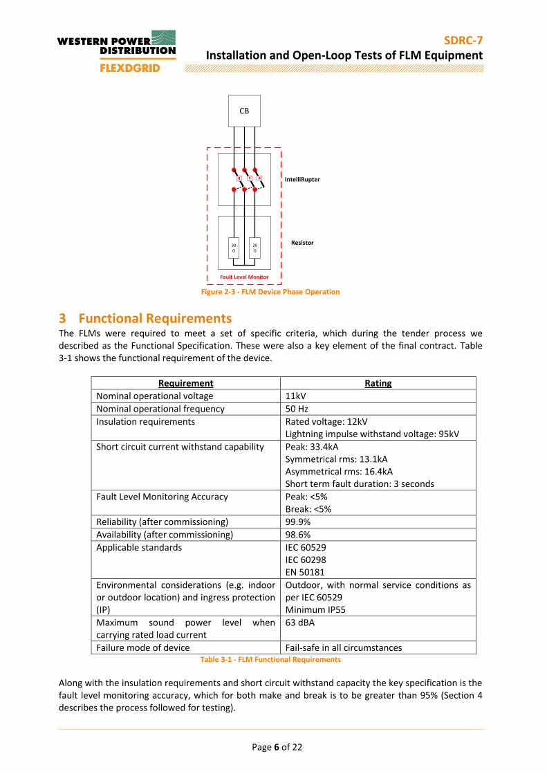
2 Device S&C Electric were the successful tenderer for the provision of 10 FLMs. The S&C Electric device is made up of four distinct components, Pad-Mounted IntelliRupter (PMIR), Resistor, PM7000 and Envoy. These four devices provide the following functions: PMIR – Pulse closing operation to create phase to phase connection; Resistor – Damping effect on current and minimisation of voltage disturbance; PM7000 – Power quality monitor to generate fault level values; and Envoy – Control and data capture system. The S&C Electric FLMs generate make and break fault level values by pulse-closing the PMIR between two phases on the 11kV network, which is subsequently dampened through a resistor, to generate a maximum current of 600A and a 1.5% voltage deviation for a period of 5ms. This voltage and current change is then captured within the PM7000, which uses the current and voltage disturbances to generate the real-time system fault levels. This information is then, through the Envoy, captured and stored in the iHost database. The Envoy device also controls the frequency of the pulse-closing activity. The operation described above is the Artificial Disturbance (AD) element of the device. The device can also extrapolate make and break fault level values based on Natural Disturbances (ND). NDs are disturbances caused on the network by such activities as tap-changing, switching load and / or generation off and on to the network and changing the arrangement of the network. Typically an ND is of a smaller current and voltage disturbance than an AD, however, lasts considerably longer, in the region of 200ms to 500ms. Finally, the device can also detect whether a substation is operating in split or parallel operation. This is performed by comparing the current and voltage waveform characteristics through each transformer. This is specifically used to quantify fault level results based on network arrangement. Below is a selection of photographs of the FLM components.

Page 5 of 22
SDRC-7 Installation and Open-Loop Tests of FLM Equipment
Figure 2-1 - PMIR and Resistor installed at Nechells West Substation
Figure 2-2 - 3 off PM7000s and Envoy installed in FLM Control Cubicle
Page 6 of 22
SDRC-7 Installation and Open-Loop Tests of FLM Equipment
CB
Fault Level Monitor
30Ω
20Ω
RYB IntelliRupter
Resistor
Figure 2-3 - FLM Device Phase Operation
3 Functional Requirements The FLMs were required to meet a set of specific criteria, which during the tender process we described as the Functional Specification. These were also a key element of the final contract. Table 3-1 shows the functional requirement of the device.
Requirement Rating
Nominal operational voltage 11kV
Nominal operational frequency 50 Hz
Insulation requirements Rated voltage: 12kV Lightning impulse withstand voltage: 95kV
Short circuit current withstand capability Peak: 33.4kA Symmetrical rms: 13.1kA Asymmetrical rms: 16.4kA Short term fault duration: 3 seconds
Fault Level Monitoring Accuracy Peak: <5% Break: <5%
Reliability (after commissioning) 99.9%
Availability (after commissioning) 98.6%
Applicable standards IEC 60529 IEC 60298 EN 50181
Environmental considerations (e.g. indoor or outdoor location) and ingress protection (IP)
Outdoor, with normal service conditions as per IEC 60529 Minimum IP55
Maximum sound power level when carrying rated load current
63 dBA
Failure mode of device Fail-safe in all circumstances Table 3-1 - FLM Functional Requirements
Along with the insulation requirements and short circuit withstand capacity the key specification is the fault level monitoring accuracy, which for both make and break is to be greater than 95% (Section 4 describes the process followed for testing).

Page 7 of 22
SDRC-7 Installation and Open-Loop Tests of FLM Equipment
4 Testing The three key elements to test, prior to installation on the 11kV network, were the short circuit withstand, insulation requirements and the device’s accuracy in relation to fault level prediction accuracy.
4.1 Short Circuit Withstand As per Section 3 it is required that the complete device can withstand 33.4kA Peak and 13.1kA Symmetrical rms fault current. The PMIR has already been tested and certified that it met these requirements. The Resistor, manufactured by HVR, which is made up of several smaller ceramic resistors to make one complete resistance, was tested in HVR’s high current testing facility in Jarrow, England.
4.2 Insulation Requirements The device must have a lightning impulse rating of 95kV and a voltage withstand rating of 28kV for one minute. As with the short circuit withstand requirements the PMIR had already been tested and certified against both of these requirements, however, the Resistor needed, for the purposes of satisfying the functional requirements, to be tested. These tests, which were carried out in S&C’s HV laboratory in Chicago, USA, were performed on the complete 11kV system, i.e. with the PMIR and Resistor in place. The standard approach to 11kV switchgear testing was taken, where the device was subjected to 15 positive and 15 negative lightning impulses and each phase with 28kV for one minute. In order to satisfy this test no breakdown must been seen during or after the testing; this is proven through insulation resistance tests being performed pre and post-tests with no difference being identified. Following these tests being performed no insulation breakdown was observed.
4.3 Fault Level Prediction Accuracy In order to fully test the accuracy of the fault levels provided by the PM7000 a high power laboratory was required. S&C, at their manufacturing facility in Chicago, have a laboratory that is capable of providing, at the same time, 11kV and in excess of 33.4kA. As this was the first time this configuration of system had been tested as to its accuracy of fault level prediction it was imperative that a selection of both peak (10ms) and rms (90ms) values were chosen to ensure the device was suitable for connection on a variety of systems. Figure 4-1 shows the laboratory setup in schematic format and Figure 4-2 shows the series of tests carried out to verify the accuracy of the system.
Figure 4-1 - Test Lab Schematic

Page 8 of 22
SDRC-7 Installation and Open-Loop Tests of FLM Equipment
Figure 4-2 - FL Test Schedule
Prior to the test of the FLM being carried a 3-phase bolted fault was carried out in the laboratory, tests 1, 6 and 11. These tests enabled a clear understanding of both the make and break fault levels of the laboratory network created. A series of artificial disturbances were created, through different resistance values, 20Ω, 30Ω and 50Ω, and the results were captured. A photograph of the laboratory can be seen in Figure 4-3 and the results are presented in Figure 4-4.
Figure 4-3 - Test Lab during FL Tests

Page 9 of 22
SDRC-7 Installation and Open-Loop Tests of FLM Equipment
Figure 4-4 - FL Test Results
The results for both make (Peak @ 10ms) and break (RMS and 90ms) fault levels are illustrated in Figure 4-4. The three distinct sections of results demonstrate three separate laboratory configurations, described in Figure 4-2, where each configuration has a different X/R ratio and fault level values. It was identified during testing that the 50Ω impedance operations did not give the required accuracy, therefore have not been considered in the results. This also informed key learning that a smaller impedance value, meaning greater current generated, produces a more accurate value. It can be seen through the figures identified in the yellow boxes, which is the overall percentage error, based on a number of tests carried out and repeated for the same system, are within the 5% limits set up at the start of the project. The fault level values given in Figure 4-4 that are shaded red are values that, on their own, are above the allowable limit. However, these values have been identified to have been caused by the unique environments associated with test environments. The two causes were that of frequency drop off that would not happen on a network and sequence closing issues of the laboratory equipment.

Page 10 of 22
SDRC-7 Installation and Open-Loop Tests of FLM Equipment
5 Installation The 10 FLMs have been installed between 2014 and 2015. Table 5-1 details the exact energisation date of each FLM. Appendices A to J provide a detailed document on the design, commissioning and energisation of each FLM.
Substation Date of energisation
Elmdon 22/10/2014
Chad Valley 02/12/2014
Castle Bromwich 12/02/2015
Shirley 04/03/2015
Kitts Green 04/03/2015
Hall Green 01/04/2015
Nechells West 29/07/2015
Chester Street 13/08/2015
Bartley Green 03/09/2015
Bournville 28/10/2015 Table 5-1 - Energisation dates of FLMs

Page 11 of 22
SDRC-7 Installation and Open-Loop Tests of FLM Equipment
6 Lessons Learnt
6.1 Design and Installation Through the process of design, installation, commissioning and operation of the FLM at ten substations, many lessons were learnt. Below is a series of issues and lessons learnt through the installation of the units. During the design stage for each substation and through the FLM installation works the following key lessons were learnt.
Where Issue Lesson Learnt
Various Existing drawing records not complete and in some cases not matching site. This meant more time was spent carrying out site surveys than planned and the production of as built drawings to ensure any design work was correct.
Extra allowance required to ensure records are corrected. Ensure that as built drawings are uploaded onto the system.
Elmdon Civil design included cable ducts running through the intellirupter foundation for HV cables. Civil contractor believed that this would be difficult to achieve.
Foundation redesigned with a cut-out for the HV cables. This would make the “boxing out” simpler and also enable greater flexibility when bending the cables into place
Elmdon Two Fibre Optic cables damaged during or post initial installation and before any commissioning works had taken place. Investigation of the damaged cable attributed the main cause to rodents eating the outer sheath of the cable, however damage was also caused when cable ties were over tightened, crushing the cable.
Ensure substations are suitably maintained with anti-rodent devices. Armoured Fibre Optic cables to be specified for all sites to minimise the risk of damage during cable installation and from 3rd parties post installation.
Various The wiring inside the cabinet for connection to the WPD CTs was undersized compared to the standard wiring used inside the switchgear. The wiring was rated for normal current however it would potentially not withstand currents experienced during a fault.
All CT wiring was changed in each control cabinet before any commissioning works commenced.
Chad Valley
Following site surveys and initial design work, it was discovered on a visit to the site that works had been carried out that affected the cable route design. A re-routing of the HV cables was carried out, removing any clashes.
Ensure all future works are known before commencement of design works. This will ensure that minimum alterations are required when work starts on site.

Page 12 of 22
SDRC-7 Installation and Open-Loop Tests of FLM Equipment
Shirley The IntelliRupter, after installation on site, showed signs of water ingress in the form of condensation inside the cable termination compartment and also the device itself. After investigation by the supplier it was determined that, despite visiting multiple previous installations, the device was not installed correctly and required caulking to the foundation.
All previous sites checked for water ingress and where appropriate remedial actions carried out. Installation contractors also made fully aware of installation manual for the device to ensure installation as per manufacturer’s full instructions.
Bartley Green
Following site works, the contractor highlighted that they installed a different sized earth bar to that specified. The bar installed is the size typically used in 11kV applications, however as the FLM was positioned within a 132kV compound, this earth bar size was inadequate requiring the contractor replace
Greater emphasis to be provided on drawings where designs may differ from previous installations. Construction supervisors should also carry out more checks during site works to ensure that designs are being followed.
6.2 Commissioning Through the commissioning process at each substation the following lessons were learnt.
Site Issue Lesson Learnt
Elmdon GPRS signal strength using antenna built into the FLM control cabinet is too low inside the switchroom due to proximity to other equipment and thickness of walls.
External antenna to be used and where possible placed on outside of the building or if not possible, as close as, and as high as possible.
Elmdon The different CT ratios between the transformer incomers and the FLM breaker were not appreciated at design stage by the manufacturer. This required the CT wiring to be double looped round the measuring CT to minimise the amount of additional gain required inside the PM7000
Length of CT wiring to be extended to allow easy installation of additional loops
Chad Valley
The circuit breaker status signals wired to the FLM controller were installed the wrong way round by the contractor. This was caused by a confusion of labelling on the wiring diagram.
Terminations reversed on site. Supplier updated drawings with a clearer terminology to assist installation contractors.
Chad Valley
The PM7000 manufacturer, following analysis of other FLM data, had produced the next version of firmware and wanted to use this on the day of commissioning without any prior testing carried out to ensure integration with the other elements of the FLM.
Proven firmware installed and an offline test bed created to prove any revisions to firmware before installation at any live site.
Page 13 of 22
SDRC-7 Installation and Open-Loop Tests of FLM Equipment
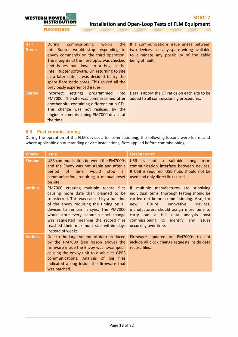
Hall Green
During commissioning works the IntelliRupter would stop responding to envoy commands on the third operation. The integrity of the fibre optic was checked and issues put down to a bug in the IntelliRupter software. On returning to site at a later date it was decided to try the spare fibre optic cores. This solved all the previously experienced issues.
If a communications issue arises between two devices, use any spare wiring available to eliminate any possibility of the cable being at fault.
Shirley Incorrect settings programmed into PM7000. The site was commissioned after another site containing different ratio CTs. This change was not realised by the engineer commissioning PM7000 device at the time.
Details about the CT ratios on each site to be added to all commissioning procedures.
6.3 Post commissioning During the operation of the FLM device, after commissioning, the following lessons were learnt and where applicable on outstanding device installations, fixes applied before commissioning.
Where Issue Lesson Learnt
Elmdon USB communication between the PM7000s and the Envoy was not stable and after a period of time would stop all communication, requiring a manual reset on site.
USB is not a suitable long term communication interface between devices. If USB is required, USB hubs should not be used and only direct links used.
Various PM7000 creating multiple record files causing more data than planned to be transferred. This was caused by a function of the envoy requiring the timing on all devices to remain in sync. The PM7000 would store every instant a clock change was requested meaning the record files reached their maximum size within days instead of weeks.
If multiple manufactures are supplying individual items, thorough testing should be carried out before commissioning. Also, for new future innovative devices, manufacturers should assign more time to carry out a full data analysis post commissioning to identify any issues occurring over time.
Various Due to the large volume of data produced by the PM7000 (see lesson above) the firmware inside the Envoy was “swamped” causing the envoy unit to disable its GPRS communications. Analysis of log files indicated a bug inside the firmware that was patched.
Firmware updated on PM7000s to not include all clock change requests inside data record files.
Page 14 of 22
SDRC-7 Installation and Open-Loop Tests of FLM Equipment
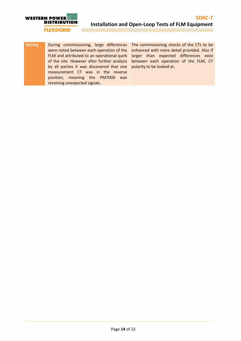
Shirley During commissioning, large differences were noted between each operation of the FLM and attributed to an operational quirk of the site. However after further analysis by all parties it was discovered that one measurement CT was in the reverse position, meaning the PM7000 was receiving unexpected signals.
The commissioning checks of the CTs to be enhanced with more detail provided. Also if larger than expected differences exist between each operation of the FLM, CT polarity to be looked at.
Page 15 of 22
SDRC-7 Installation and Open-Loop Tests of FLM Equipment
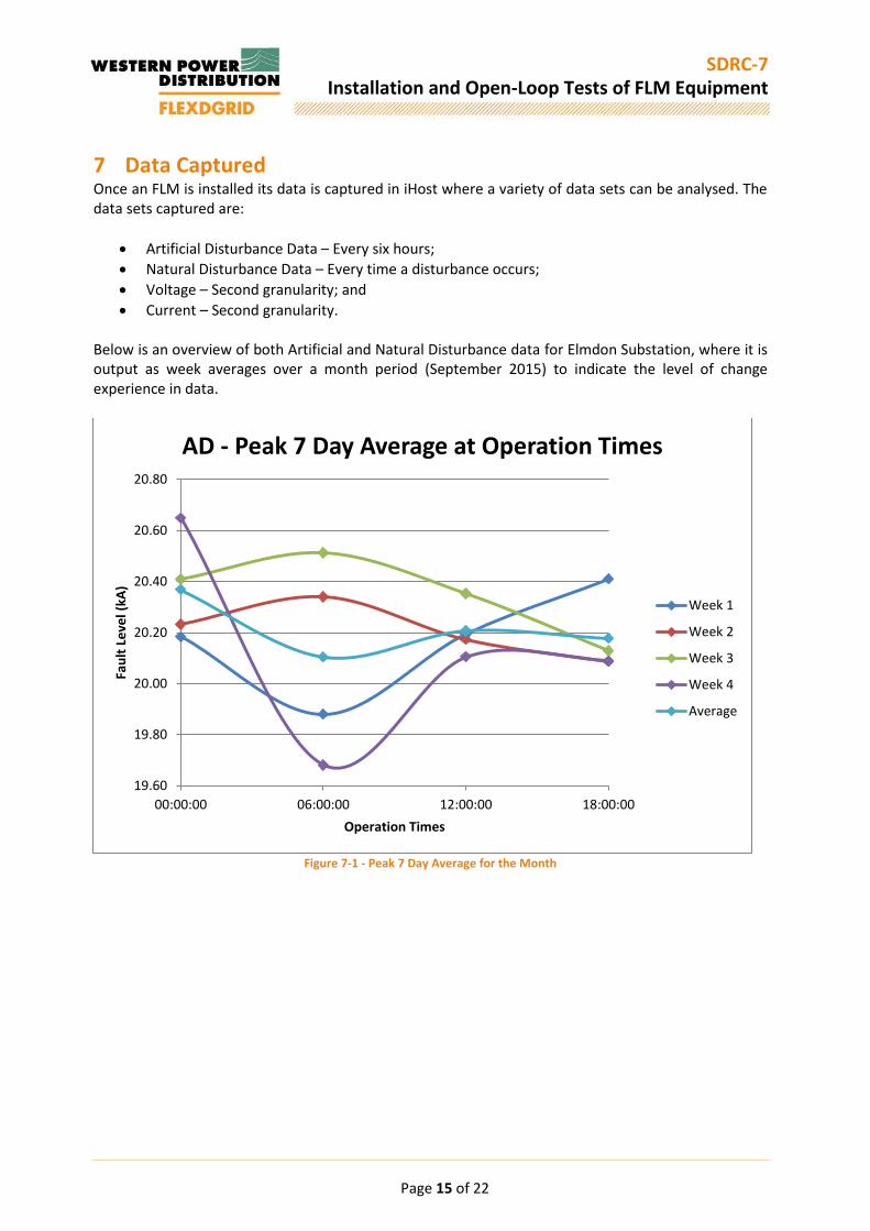
7 Data Captured Once an FLM is installed its data is captured in iHost where a variety of data sets can be analysed. The data sets captured are:
Artificial Disturbance Data – Every six hours;
Natural Disturbance Data – Every time a disturbance occurs;
Voltage – Second granularity; and
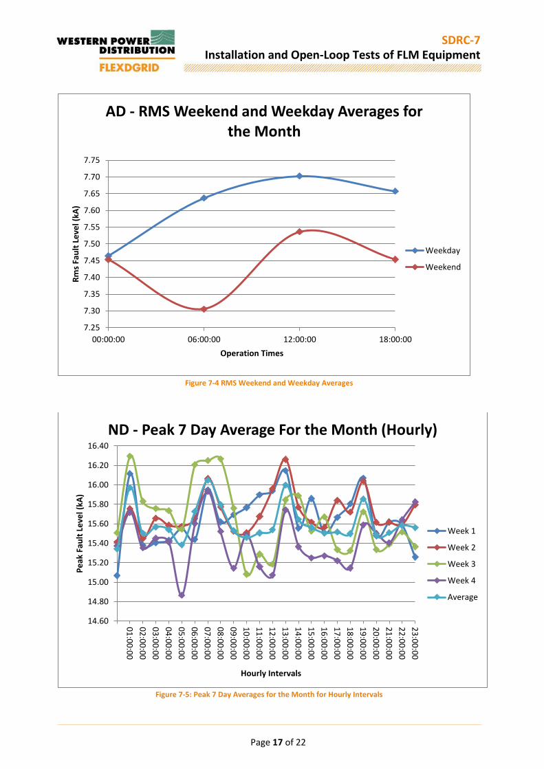
Current – Second granularity. Below is an overview of both Artificial and Natural Disturbance data for Elmdon Substation, where it is output as week averages over a month period (September 2015) to indicate the level of change experience in data.
Figure 7-1 - Peak 7 Day Average for the Month
19.60
19.80
20.00
20.20
20.40
20.60
20.80
00:00:00 06:00:00 12:00:00 18:00:00
Fau
lt L
eve
l (kA
)
Operation Times
AD - Peak 7 Day Average at Operation Times
Week 1
Week 2
Week 3
Week 4
Average

Page 16 of 22
SDRC-7 Installation and Open-Loop Tests of FLM Equipment
Figure 7-2: RMS 7 Day Averages for the Month
Figure 7-3: Peak Weekend and Weekday Averages
7.35
7.40
7.45
7.50
7.55
7.60
7.65
7.70
7.75
00:00:00 06:00:00 12:00:00 18:00:00
Fau
lt L
eve
l (kA
)
Operation Times
AD - RMS 7 Day Averages at Operation Times
Week 1
Week 2
Week 3
Week 4
Average
19.20
19.40
19.60
19.80
20.00
20.20
20.40
20.60
00:00:00 06:00:00 12:00:00 18:00:00
Pe
ak F
ault
Le
vel (
kA)
Operation Times
AD - Peak Weekend and Weekday Average for the Month
Weekday
Weekend
Page 17 of 22
SDRC-7 Installation and Open-Loop Tests of FLM Equipment
Figure 7-4 RMS Weekend and Weekday Averages
Figure 7-5: Peak 7 Day Averages for the Month for Hourly Intervals
7.25
7.30
7.35
7.40
7.45
7.50
7.55
7.60
7.65
7.70
7.75
00:00:00 06:00:00 12:00:00 18:00:00
Rm
s Fa
ult
Le
vel (
kA)
Operation Times
AD - RMS Weekend and Weekday Averages for the Month
Weekday
Weekend
14.60
14.80
15.00
15.20
15.40
15.60
15.80
16.00
16.20
16.40
01
:00
:00
02
:00
:00
03
:00
:00
04
:00
:00
05
:00
:00
06
:00
:00
07
:00
:00
08
:00
:00
09
:00
:00
10
:00
:00
11
:00
:00
12
:00
:00
13
:00
:00
14
:00
:00
15
:00
:00
16
:00
:00
17
:00
:00
18
:00
:00
19
:00
:00
20
:00
:00
21
:00
:00
22
:00
:00
23
:00
:00
Pe
ak F
ault
Le
vel (
kA)
Hourly Intervals
ND - Peak 7 Day Average For the Month (Hourly)
Week 1
Week 2
Week 3
Week 4
Average
Page 18 of 22
SDRC-7 Installation and Open-Loop Tests of FLM Equipment
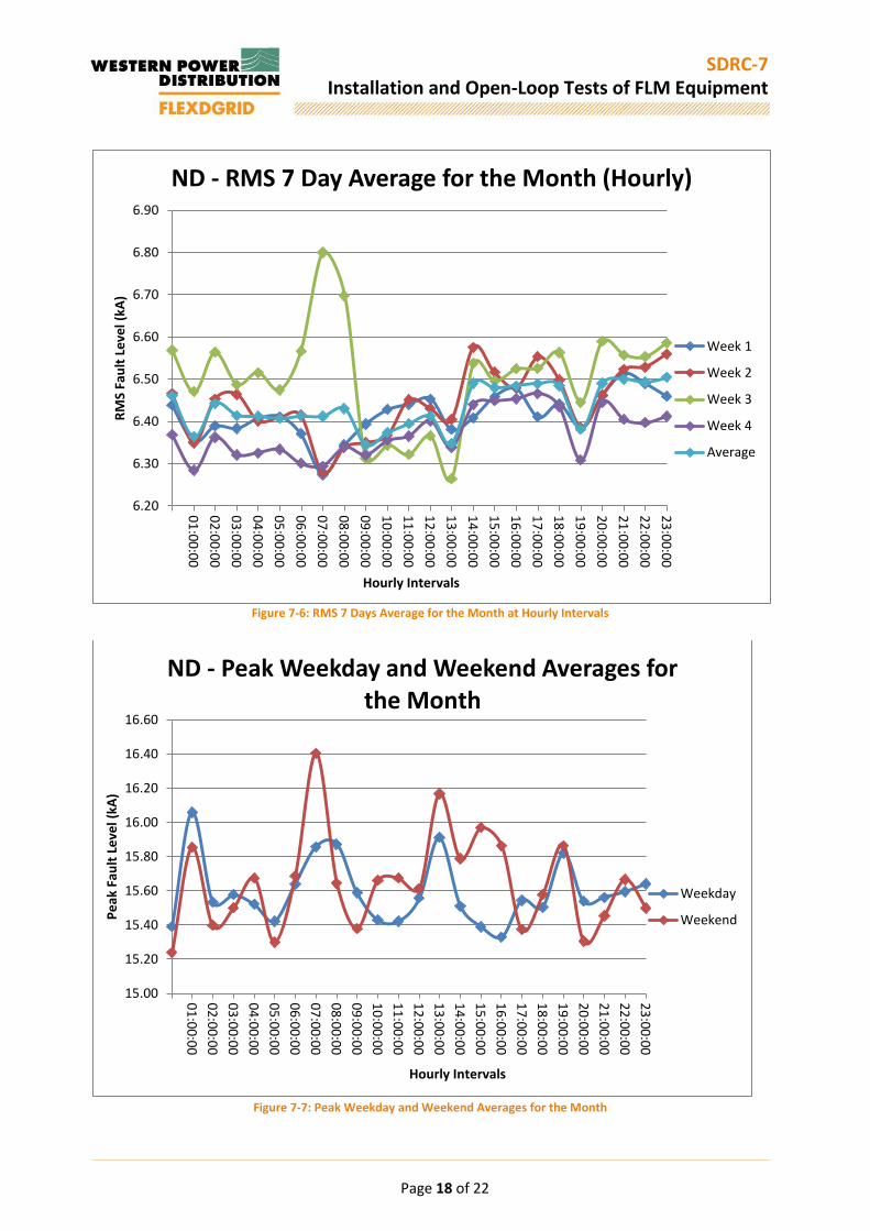
Figure 7-6: RMS 7 Days Average for the Month at Hourly Intervals
Figure 7-7: Peak Weekday and Weekend Averages for the Month
6.20
6.30
6.40
6.50
6.60
6.70
6.80
6.90
01
:00
:00
02
:00
:00
03
:00
:00
04
:00
:00
05
:00
:00
06
:00
:00
07
:00
:00
08
:00
:00
09
:00
:00
10
:00
:00
11
:00
:00
12
:00
:00
13
:00
:00
14
:00
:00
15
:00
:00
16
:00
:00
17
:00
:00
18
:00
:00
19
:00
:00
20
:00
:00
21
:00
:00
22
:00
:00
23
:00
:00
RM
S Fa
ult
Le
vel (
kA)
Hourly Intervals
ND - RMS 7 Day Average for the Month (Hourly)
Week 1
Week 2
Week 3
Week 4
Average
15.00
15.20
15.40
15.60
15.80
16.00
16.20
16.40
16.60
01
:00
:00
02
:00
:00
03
:00
:00
04
:00
:00
05
:00
:00
06
:00
:00
07
:00
:00
08
:00
:00
09
:00
:00
10
:00
:00
11
:00
:00
12
:00
:00
13
:00
:00
14
:00
:00
15
:00
:00
16
:00
:00
17
:00
:00
18
:00
:00
19
:00
:00
20
:00
:00
21
:00
:00
22
:00
:00
23
:00
:00
Pe
ak F
ault
Le
vel (
kA)
Hourly Intervals
ND - Peak Weekday and Weekend Averages for the Month
Weekday
Weekend
Page 19 of 22
SDRC-7 Installation and Open-Loop Tests of FLM Equipment
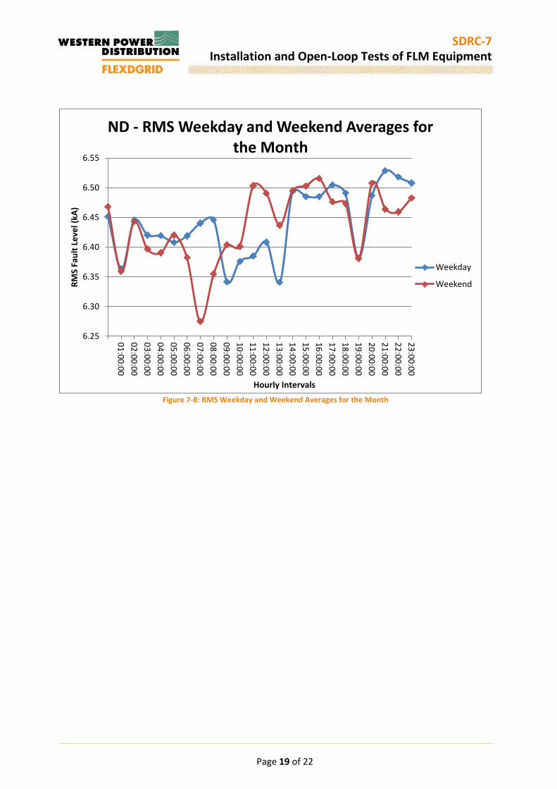
Figure 7-8: RMS Weekday and Weekend Averages for the Month
6.25
6.30
6.35
6.40
6.45
6.50
6.55
01
:00
:00
02
:00
:00
03
:00
:00
04
:00
:00
05
:00
:00
06
:00
:00
07
:00
:00
08
:00
:00
09
:00
:00
10
:00
:00
11
:00
:00
12
:00
:00
13
:00
:00
14
:00
:00
15
:00
:00
16
:00
:00
17
:00
:00
18
:00
:00
19
:00
:00
20
:00
:00
21
:00
:00
22
:00
:00
23
:00
:00
RM
S Fa
ult
Le
vel (
kA)
Hourly Intervals
ND - RMS Weekday and Weekend Averages for the Month
Weekday
Weekend

Page 20 of 22
SDRC-7 Installation and Open-Loop Tests of FLM Equipment
8 Next Steps Following the successful installation of the 10 FLMs the next steps are to use the data provided, as described in Section 7, for closed loop operation. In this section the three elements of closed loop operation will be described.
8.1 Model Updates Through the learning generated to date and moving forwards in to the final year of the project, the focus of the FLM data, in relation to the Power System Analysis (PSA) software modelling updates, is to use the data to inform the updated fault level MVA/MVA infeed. G74 currently states that in the absence of monitored and / or measured values to represent the LV network on the 11kV network a value of 1MVA/MVA should be used. Through the use of actual, monitored, data values are to be proposed for each of the monitored substation as a more accurate representation of the fault level infeed, due to the varying load and generation connection types at each primary substation. Initial work has begun to understand what the revised fault level infeed values may be. A variety of examples are provided for Elmdon below, where different times of day and week are considered.
Figure 8-1 - Elmdon MVA/MVA Analysis
It can be seen that for each considered condition the MVA/MVA infeed is always significantly greater than that proposed in G74 (1MVA/MVA). This work will be considered for all substations over a period of time to propose updated values. These values will then be used to more fully understand the fault level of the substation considered. The final aim is to be able to categorise substation fault level infeed by the type of load connected (domestic, industrial and commercial), which will allow a wider role out of an updated fault level infeed methodology.
8.2 Network Management Centre Currently there is no fault level information captured in the Network Management Centre (NMC), which is the live operational centre for the network. Throughout the remainder of the project the role and value of real time fault levels in the NMC will be investigated. A key element of this is presenting the live, make and break, fault levels in WPD’s NMC software, PowerOn Fusion. Through the presentation of fault level data the aim is to enable greater optimisation of the existing network, more information to allow control engineers to make operation decisions and the effects of network configuration changes on fault level.
MVA/MVA per 00:00 06:00 12:00 18:00 Average
1 month 2.1 2.2 2.5 2.3 2.3
weekdays of 1 month 2.2 2.3 2.5 2.6 2.4
weekends of 1 month 2.1 1.8 3.0 1.8 2.2
week 1 2.4 2.5 2.8 2.5 2.6
week 2 1.6 2.2 2.4 2.0 2.1
week 3 2.8 2.6 2.7 2.5 2.7
week 4 1.9 2.0 2.3 2.5 2.2
weekdays of week 1 2.6 3.3 2.4 2.0 2.6
weekdays of week 2 1.7 2.0 2.5 2.3 2.1
weekdays of week 3 2.9 2.8 2.8 2.9 2.9
weekdays of week 4 1.6 2.3 2.2 2.8 2.2
Average 2.2 2.4 2.6 2.4
Elmdon

Page 21 of 22
SDRC-7 Installation and Open-Loop Tests of FLM Equipment
8.3 Customer Connections Along with the information described in Section 8.1 to enable more accurate fault levels to be modelled to support customer connections, the final key element of closed loop operation is to determine and document a process to enable flexible customer connections through the use of FLM data. The element of work will be supported by the previous WPD learning through the development of thermal and voltage based alternative connections. The aim is to use the real-time FLM data to support additional customer connections, where possible, by understanding the actual fault level at any specific point in time to make a decision to enable a load or generator to operate.
9 Appendices A – Kitts Green Installation Report B – Castle Bromwich Installation Report C – Chester Street Installation Report D – Bournville Installation Report E – Bartley Green Installation Report F – Hall Green Installation Report G – Elmdon Installation Report H – Chad Valley Installation Report I – Shirley Installation Report J – Nechells West Installation Report

Page 22 of 22
SDRC-7 Installation and Open-Loop Tests of FLM Equipment
Check List
Analysis Methodology
Page 1 of 1
SDRC-7 Installation and Open-Loop Tests of FLM Equipment
Appendix A - Kitts Green Installation Report

FLM Installation Report Kitts Green

FLM Installation Report Kitts Green
Document Control
Name Date Prepared by: Paul Edwards 02.10.2015
Reviewed by: Jonathan Berry 19.11.2015
Approved (WPD): Jonathan Berry 19.11.2015
Revision History
Date Issue Status 02.10.2015 D01 Draft
19.11.2015 V01 FINAL
Report Title : FLM Installation Report Kitts Green
Report Status : FINAL
Project Ref : WPDT2004 - FlexDGrid
Date : 19.11.2015
Page 2 of 6

FLM Installation Report Kitts Green
1 Introduction The following report details the design, installation and commissioning of the Fault Level Monitor at Kitts Green 132/11kV Substation. This was the fourth Fault Level Monitor commissioned as part of FlexDGrid. The report aims to disseminate information about the installation and commissioning of the FLM at this substation and the learning taken forward to the subsequent FLM installations. 2 Substation Overview Kitts Green 132/11kV Substation is located around 5 miles east of Birmingham City Centre. The substation is normally supplied from Lea Marston G.S.P and consists of 3 no. 132/11/11kV 60MVA transformers with each winding supplying a section on 11kV switchboard. The substation was commissioned in 2008 with all equipment located inside a brick building.
GT1
MESH CORNER 1/LEA MARSTON
BS U-VSECU
SECV
GT1A GT1B
BS V-W
GT2
MESH CORNER 2/LEAMARSTON
BS W-X SECX
GT2A
BS X-Y
GT2B
SECW
GT3
BOUGHTONROAD
BS Y-Z SECZ
GT3A GT3B
SECY3RM 51RM4RM
VT VT VT VT VT VT
SPAR
E
9x630mm²
132/11/11kV60/30/30MVA
132/11/11kV60/30/30MVA
132/11/11kV60/30/30MVA
2000A
2000A
2000A
2000A
Figure 2-1 - Original Kitts Green SLD 3 Connection and Design Due to the availability of a suitable spare breaker on the existing 11kV switchboard, this was selected as the preferred HV connection method. A large area of land, within the substation boundary, was available to the east of the switch-house so it was decided that the FLM was to be positioned inside its own compound in this area. Records indicated that the majority of the 11kV feeder cables run through this area, so a ground radar survey was carried out to locate all the cables so the compound could be safely positioned without impacting any existing cables.
Page 3 of 6

FLM Installation Report Kitts Green
GT1
MESH CORNER 1/LEA MARSTON
BS U-VSECU
SECV
GT1A GT1B
BS V-W
GT2
MESH CORNER 2/LEAMARSTON
BS W-X SECX
GT2A
BS X-Y
GT2B
SECW
GT3
BOUGHTONROAD
BS Y-Z SECZ
GT3A GT3B
SECY3RM 51RM4RM
FLM
VT VT VT VT VT VT
9x630mm²
132/11/11kV60/30/30MVA
132/11/11kV60/30/30MVA
132/11/11kV60/30/30MVA
2000A
2000A
2000A
2000A
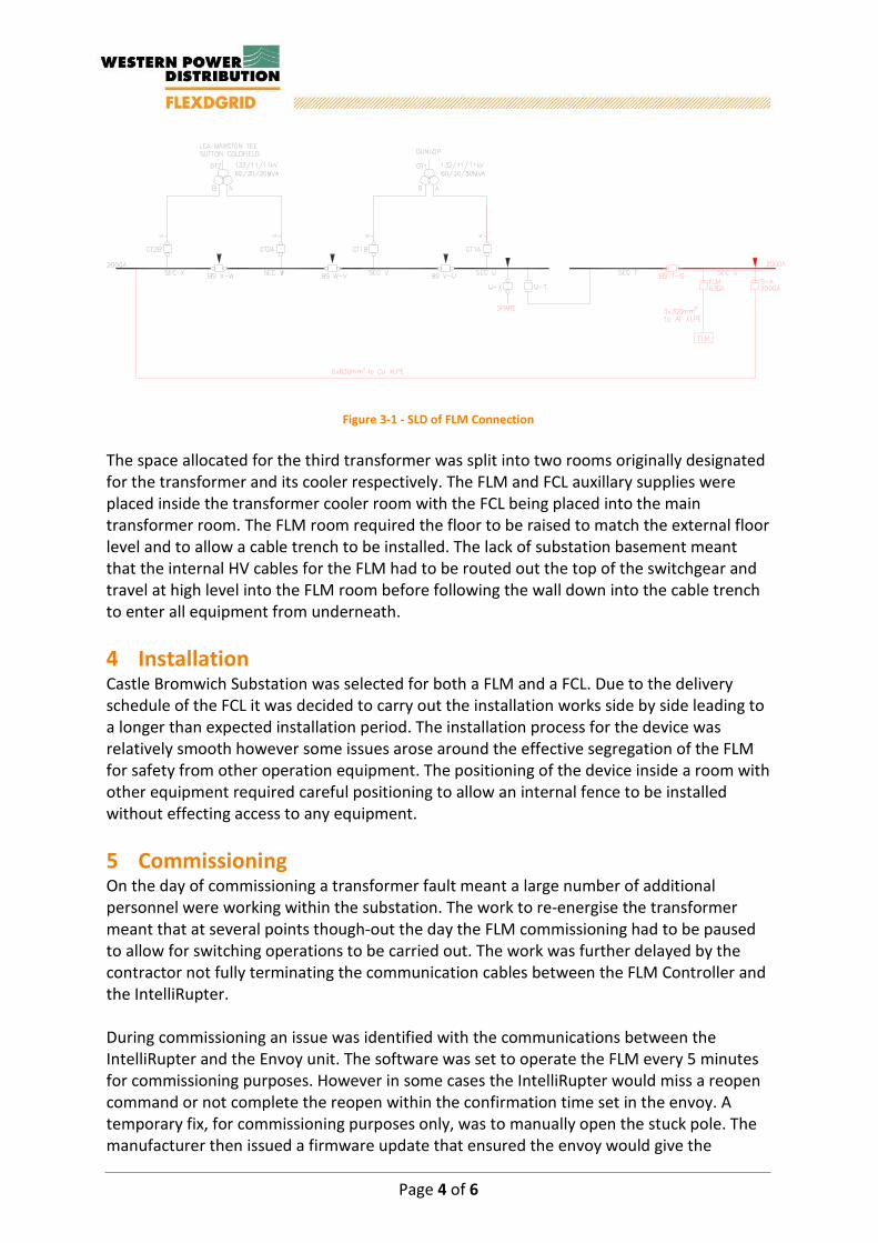
Figure 3-1 - SLD of FLM Connection
The FLM control cabinet was to be positioned at the end of the switchboard, close to the FLM feeder panel. The normal running arrangement of the substation is with each winding of the double wound transformer in parallel. Due to this arrangement, a unique wiring design was required for the controller to be able to accept 4 no. transformer CT inputs instead of the usual two. The large excavation carried out during the original substation construction meant that the soil structure at the substation is very weak and therefore a specialist foundation design was required. This required a foundation around twice as deep as required at other substations with ducts contained within the foundation for the HV cables. 4 Installation The installation works on site began in September 2014 with commencement of the civil works, installing the foundations for the IntelliRupter and Resistor and installation of the new compound fence. Due to the short cable length it was decided that the cable would be laid direct and jointed into the existing cable from the spare breaker. The existing cable was around 50m in length with the joint location at around 10m along the cable. The cable was capped and therefore earthed at the circuit breaker and in order to make the cable safe following the cutting and jointing onto the new cable, the capped end would have to be removed and the cable earthed. However, the end of the cable was difficult for the contractors to locate and this lead to delays in the installation. The installation works were also affected by the availability of transformer outages. This site required CT connections from four transformer windings. Due to the time of the year, the organisation of transformer outages was restricted and affected by other network issues. This meant that outages could not be organised to coincide with the electrical programme of works delaying the final commissioning of the site.
Page 4 of 6

FLM Installation Report Kitts Green
5 Commissioning During the commissioning of the substation it was identified that the measurement CT’s installed were of the incorrect ratio so were swapped with ones capable of handling the larger input currents. Another issue identified was that in order to effectively measure disturbances when transformers are paralleled the current from all the transformers needs to be measured by the same CT to create a single input to the PM7000. At this site, with the potential to parallel four transformer windings, the combined current at maximum load would be 20 amps. The largest measurement CTs are only capable of handling 10 amps so therefore two CTs instead of the usual one were used and then connected in series so their outputs are combined. Post commissioning the communications network was interrupted with the unit going offline with no data being transmitted. Upon visiting site the unit appeared to be working correctly with no visible signs that things were wrong. After resetting the device everything went back to normal again so at the time the issue was attributed to a one off external event. However, the same thing occurred at a second site following this and a deeper investigation confirmed that the issue was caused by the device trying to transmit a large amount of data at the same time leading to the network being overloaded and effectively shutting down. A firmware update was applied following this and no further issues were experienced. 6 Photos
Figure 6-1 - FLM Compound Figure 6-2 - FLM 11kV Circuit Breaker
Figure 6-3 - FLM Control Cubicle Figure 6-4 - FLM Antenna
Page 5 of 6


Page 1 of 1
SDRC-7 Installation and Open-Loop Tests of FLM Equipment
Appendix B – Castle Bromwich Installation Report

FLM Installation Report Castle Bromwich

FLM Installation Report Castle Bromwich
Document Control
Name Date Prepared by: Paul Edwards 02.10.2015
Reviewed by: Jonathan Berry 19.11.2015
Approved (WPD): Jonathan Berr 19.11.2015
Revision History
Date Issue Status 02.10.2015 D01 Draft
19.11.2015 V01 FINAL
Report Title : FLM Installation Report Castle Bromwich
Report Status : FINAL
Project Ref : WPDT2004 - FlexDGrid
Date : 19.11.2015
Page 2 of 6

FLM Installation Report Castle Bromwich
1 Introduction The following report details the design, installation and commissioning of the Fault Level Monitor at Castle Bromwich 132/11kV Substation. This was the third Fault Level Monitor commissioned as part of FlexDGrid. The report aims to disseminate information about the installation and commissioning of the FLM at this substation and the learning taken forward to the subsequent FLM installations. 2 Substation Overview Castle Bromwich 132/11kV substation is located on the edge of a residential area approximately 6 miles north east of Birmingham City Centre. The substation consists of 2 no. 132/11/11kV 60MVA transformers with GT1 supplied from Nechalls East 400/132kV GSP and GT2 from Lea Marston 400/132kV GSP. The substation is contained within a single building with internal space available which was previously allocated to a future third transformer.
Figure 2-1 - Original Castle Bromwich SLD
3 Connection and Design There were no spare circuit breakers available on the existing switchboard for the connection of the FLM so it was decided to extend a previous switchgear extension. Due to the installation of a Fault Current Limiter and to increase operational flexibility, it was decided to also install a new interconnector panel next to the FLM feeder. The FLM controller would be placed next to this extension with CT and VT inputs required from the existing switchboard and the new FCL switchboard.
Page 3 of 6
FLM Installation Report Castle Bromwich
Figure 3-1 - SLD of FLM Connection
The space allocated for the third transformer was split into two rooms originally designated for the transformer and its cooler respectively. The FLM and FCL auxillary supplies were placed inside the transformer cooler room with the FCL being placed into the main transformer room. The FLM room required the floor to be raised to match the external floor level and to allow a cable trench to be installed. The lack of substation basement meant that the internal HV cables for the FLM had to be routed out the top of the switchgear and travel at high level into the FLM room before following the wall down into the cable trench to enter all equipment from underneath. 4 Installation Castle Bromwich Substation was selected for both a FLM and a FCL. Due to the delivery schedule of the FCL it was decided to carry out the installation works side by side leading to a longer than expected installation period. The installation process for the device was relatively smooth however some issues arose around the effective segregation of the FLM for safety from other operation equipment. The positioning of the device inside a room with other equipment required careful positioning to allow an internal fence to be installed without effecting access to any equipment. 5 Commissioning On the day of commissioning a transformer fault meant a large number of additional personnel were working within the substation. The work to re-energise the transformer meant that at several points though-out the day the FLM commissioning had to be paused to allow for switching operations to be carried out. The work was further delayed by the contractor not fully terminating the communication cables between the FLM Controller and the IntelliRupter. During commissioning an issue was identified with the communications between the IntelliRupter and the Envoy unit. The software was set to operate the FLM every 5 minutes for commissioning purposes. However in some cases the IntelliRupter would miss a reopen command or not complete the reopen within the confirmation time set in the envoy. A temporary fix, for commissioning purposes only, was to manually open the stuck pole. The manufacturer then issued a firmware update that ensured the envoy would give the Page 4 of 6
FLM Installation Report Castle Bromwich
IntelliRupter maximum time to operate and also re-issue commands to ensure that the IntelliRupter returns to its default position before the next operation. 6 Photos
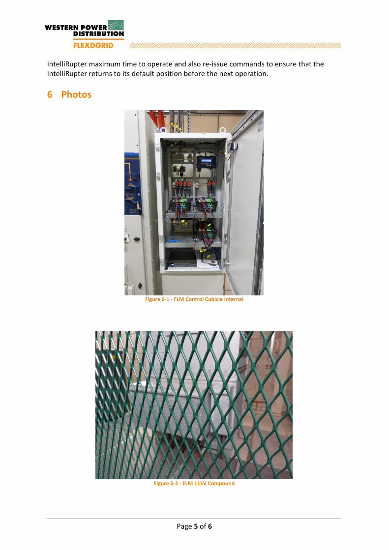
Figure 6-1 - FLM Control Cubicle Internal
Figure 6-2 - FLM 11kV Compound
Page 5 of 6


Page 1 of 1
SDRC-7 Installation and Open-Loop Tests of FLM Equipment
Appendix C – Chester Street Installation Report

FLM Installation Report Chester Street

FLM Installation Report Chester Street
Document Control
Name Date Prepared by: Paul Edwards 02.10.2015
Reviewed by: Jonathan Berry 19.11.2015
Approved (WPD): Jonathan Berry 19.11.2015
Revision History
Date Issue Status 02.10.2015 D01 Draft
19.11.2015 V01 FINAL
Report Title : FLM Installation Report Chester Street
Report Status : FINAL
Project Ref : WPDT2004 - FlexDGrid
Date : 19.11.2015
Page 2 of 7
FLM Installation Report Chester Street
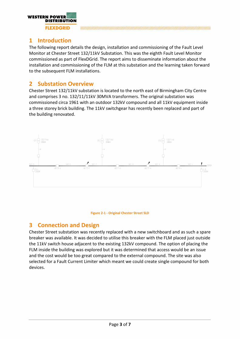
1 Introduction The following report details the design, installation and commissioning of the Fault Level Monitor at Chester Street 132/11kV Substation. This was the eighth Fault Level Monitor commissioned as part of FlexDGrid. The report aims to disseminate information about the installation and commissioning of the FLM at this substation and the learning taken forward to the subsequent FLM installations. 2 Substation Overview Chester Street 132/11kV substation is located to the north east of Birmingham City Centre and comprises 3 no. 132/11/11kV 30MVA transformers. The original substation was commissioned circa 1961 with an outdoor 132kV compound and all 11kV equipment inside a three storey brick building. The 11kV switchgear has recently been replaced and part of the building renovated.
Figure 2-1 - Original Chester Street SLD
3 Connection and Design Chester Street substation was recently replaced with a new switchboard and as such a spare breaker was available. It was decided to utilise this breaker with the FLM placed just outside the 11kV switch house adjacent to the existing 132kV compound. The option of placing the FLM inside the building was explored but it was determined that access would be an issue and the cost would be too great compared to the external compound. The site was also selected for a Fault Current Limiter which meant we could create single compound for both devices.
Page 3 of 7

FLM Installation Report Chester Street
Figure 3-1 - SLD of FLM Connection
As with the design for Shirley Substation, the Transformer Incomers do not contain metering CTs typically used for the current inputs to the FLM. Therefore, to get the CT inputs, the back-up protection CT wiring will be diverted to loop inside the FLM controller. For the FLM compound, existing drawings and Ground Radar Survey indicated that the 132kV cable ran through the middle of the proposed FLM compound location. The individual items of the FLM were designed to be positioned in such a way that no excavation works would take place near this cable and therefore remove all risks of any damage occurring to it. During the design works and site surveys it was discovered that the existing drawings concerning the earthing arrangement of the 11kV switch house and the 132kV compound were not up to date. Therefore an earthing survey was required for the complete site to ensure that the earthing for the FLM and FCL could be safely connected to the existing. 4 Installation Installation works were staged to fit around the installation and commissioning of the new switchboard and cabling works. This meant there would be a delay between the civil and electrical installation works. Upon the start of the electrical works, asbestos was discovered inside the switch house basement leading to further delays until the area was made safe. During the installation, the site team decided that they could locally manage the risk of excavation around the 132kV cable so re-positioned the FLM equipment to provide a better access arrangement into the compound but meant that the FLM equipment now straddled the cable. 5 Commissioning The FLM was commissioned in July 2015. The commissioning was delayed on the day due to the removal of equipment from the site to assist with the testing of the FLM device. On the items return from testing they were not identified correctly and therefore placed back with the rest of the equipment designated for this site.
Page 4 of 7

FLM Installation Report Chester Street
The CT ratios used on the site are different from the majority of the other sites. This was not made clear enough to the supplier during the commissioning and as such the wrong settings were programmed into the system. This meant that the currents being recorded are a factor of 10 above the actual values. With works continuing on the site and various outages of LV supplies the FLM Controller reverted to its battery supply. Around a week after the commissioning the battery supply failed. This underwent replacement alongside the correction to the FLM CT settings. 6 Photos
Figure 6-1 - FLM 11kV Compound
Page 5 of 7
FLM Installation Report Chester Street
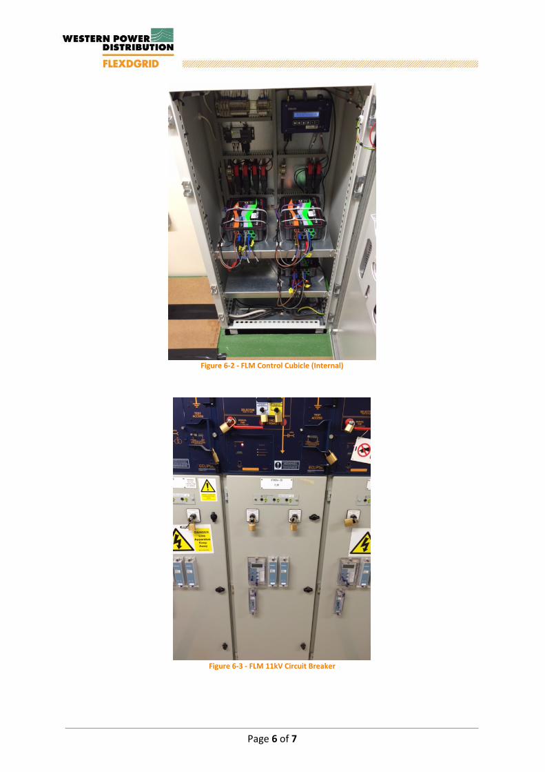
Figure 6-2 - FLM Control Cubicle (Internal)
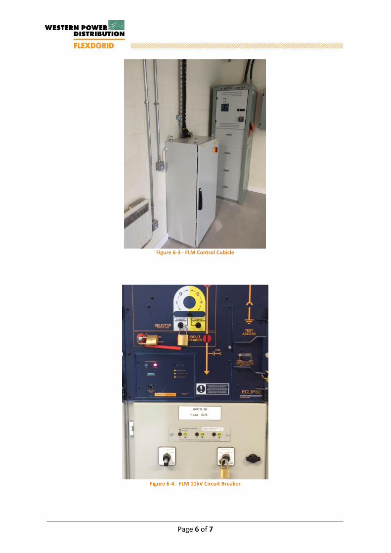
Figure 6-3 - FLM 11kV Circuit Breaker
Page 6 of 7


Page 1 of 1
SDRC-7 Installation and Open-Loop Tests of FLM Equipment
Appendix D – Bournville Installation Report

FLM Installation Report Bournville
FLM Installation Report Bournville
Document Control
Name Date Prepared by: Paul Edwards 02.10.2015
Reviewed by: Jonathan Berry 19.11.2015
Approved (WPD): Jonathan Berry 19.11.2015
Revision History
Date Issue Status 02.10.2015 D01 Draft
19.11.15 V01 FINAL
Report Title : FLM Installation Report Bournville
Report Status : FINAL
Project Ref : WPDT2004 - FlexDGrid
Date : 19.11.2015
Page 2 of 7
FLM Installation Report Bournville
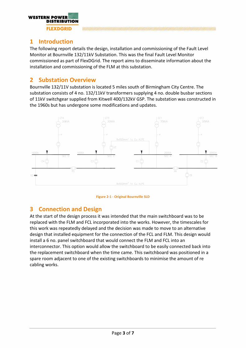
1 Introduction The following report details the design, installation and commissioning of the Fault Level Monitor at Bournville 132/11kV Substation. This was the final Fault Level Monitor commissioned as part of FlexDGrid. The report aims to disseminate information about the installation and commissioning of the FLM at this substation. 2 Substation Overview Bournville 132/11V substation is located 5 miles south of Birmingham City Centre. The substation consists of 4 no. 132/11kV transformers supplying 4 no. double busbar sections of 11kV switchgear supplied from Kitwell 400/132kV GSP. The substation was constructed in the 1960s but has undergone some modifications and updates.
Figure 2-1 - Original Bournville SLD
3 Connection and Design At the start of the design process it was intended that the main switchboard was to be replaced with the FLM and FCL incorporated into the works. However, the timescales for this work was repeatedly delayed and the decision was made to move to an alternative design that installed equipment for the connection of the FCL and FLM. This design would install a 6 no. panel switchboard that would connect the FLM and FCL into an interconnector. This option would allow the switchboard to be easily connected back into the replacement switchboard when the time came. This switchboard was positioned in a spare room adjacent to one of the existing switchboards to minimise the amount of re cabling works.
Page 3 of 7

FLM Installation Report Bournville
Figure 3-1 - SLD of FLM Connection
The substation contains two areas suitable for the installation of an FLM. These were externally in a compound between the 11kV building and the 132kV compound, or internally on the first floor in one of the old switchrooms. The internal solution was chosen as this would have a minimal impact on any future works at the substation. The room is directly above the position of the new switchboard so new cables 4 Installation The installation works began in March 2015 with modifications made to the switchroom to facilitate the installation of the new switchboard that was placed into the substation in April 2015. 5 Commissioning The FLM was commissioned on the 27th October 2015 and was the final FLM to be commissioned. The IntelliRupter and the Resistor are situated on the first floor of the switchroom building; besides the installation challenges of siting the equipment no other issues were encountered due to this. The commissioning of the device ran smoothly and benefited from the learning of all other FLM installations. Page 4 of 7

FLM Installation Report Bournville
6 Photos
Figure 6-1 - 11kV S/Gear for FLM and FCL
Figure 6-2 - FLM 11kV Compound
Page 5 of 7
FLM Installation Report Bournville
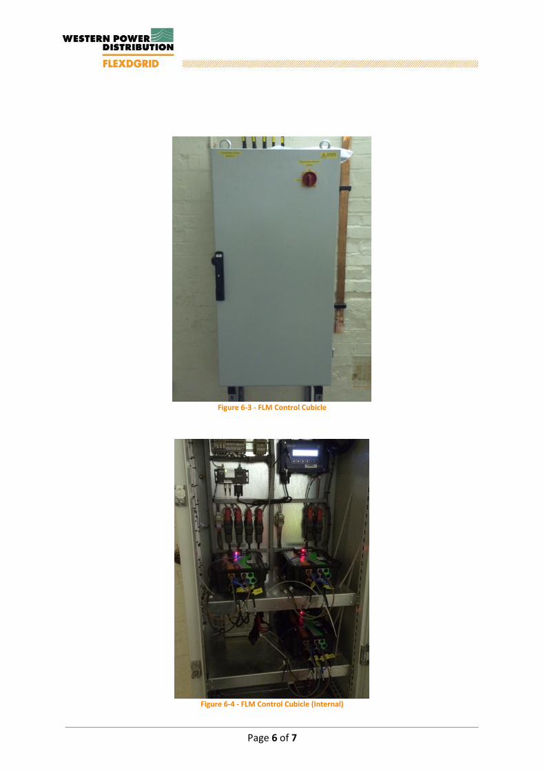
Figure 6-3 - FLM Control Cubicle
Figure 6-4 - FLM Control Cubicle (Internal)
Page 6 of 7


Page 1 of 1
SDRC-7 Installation and Open-Loop Tests of FLM Equipment
Appendix E – Bartley Green Installation Report

FLM Installation Report Bartley Green

FLM Installation Report Bartley Green
Document Control
Name Date Prepared by: Paul Edwards 02.10.2015
Reviewed by: Jonathan Berry 19.11.2015
Approved (WPD): Jonathan Berry 19.11.2015
Revision History
Date Issue Status 02.10.2015 D01 Draft
19.11.2015 V01 FINAL
Report Title : FLM Installation Report Bartley Green
Report Status : FINAL
Project Ref : WPDT2004 - FlexDGrid
Date : 19.11.2015
Page 2 of 7

FLM Installation Report Bartley Green
1 Introduction The following report details the design, installation and commissioning of the Fault Level Monitor at Bartley Green 132/11kV Substation. This was the ninth Fault Level Monitor commissioned as part of FlexDGrid. The report aims to disseminate information about the installation and commissioning of the FLM at this substation and the learning taken forward to the final FLM installation. 2 Substation Overview Bartley Green 132/11kV Substation is located around 5 miles to the south west of Birmingham City Centre. The substation comprises 2 no. 132/11kV 30MVA transformers fed from Kitwell 400/132kV GSP via Chad Valley Substation. The 11kV switchgear has recently been replaced and brand new switch-house constructed within the 132kV compound.
SEC VSEC W SEC X
GT2GT1 132/11kV30MVA
132/11kV30MVA
SEC U
BS W-X BS X-V BSV-U U-WW-U2000A 2000A
2000A
VT VT
Figure 2-1 - Original Bartley Green SLD
3 Connection and Design With the installation of a new switchboard, a spare feeder breaker was available for the connection of the FLM. Due to the large size of the 132kV compound space available, the site was chosen for the connection of a Fault Current Limiter also. With this in mind the FLM had to be positioned in conjunction with the FCL to minimise the operational area used and not impact on normal operations within the substation. An area was selected in a corner of the compound opposite one of the grid transformers that is unlikely to be used for any potential upgrades on the 132kV equipment.
Page 3 of 7

FLM Installation Report Bartley Green
SEC VSEC W SEC X
GT2GT1 132/11kV30MVA
132/11kV30MVA
SEC U
FLM
FLM
3x300mm²1c Al XLPE
BS W-X BS X-V BSV-U U-WW-U2000A 2000A 2000A
2000A
VT VT
Figure 3-1 - SLD of FLM Connection
The new switchgear installed on the site was without spare metering CTs inside the transformer incomers. Therefore the backup protection CT’s were used as per the Chester Street and Shirley installations. 4 Installation The installation of the FLM was carried out in July and August 2015. The civil works were completed without issue, with only slight delays caused by resourcing issues with the contractor. The electrical contractor had few issues with the installation with main issues revolving around the diversion of existing CT wiring to the FLM controller which they had of not carried out before. The contractor was in control of the programme and the organisation of the commissioning was in their control. Despite this, on the day of commissioning the installation of the earthing was not complete leading to long delays in the commissioning process. 5 Commissioning The commissioning of the FLM took longer than all the other sites due to the contractor still working on site to complete the installation works. This limited the supplier to carrying out offline checks and tests for a large proportion of the day. Once the contractor had completed their works the final energisation of the FLM went smoothly. Following commissioning, once as built drawings were produced, it was discovered that through an administration error by the contractor a different sized earth tape to the one specified was installed in the FLM compound. As the compound was connected to the same grid as the 132kV compound the risk of undersized earth bar could not be accepted and works carried out to replace the installed earthing with tape of the correct size.
Page 4 of 7

FLM Installation Report Bartley Green
6 Photos
Figure 6-1 - FLM 11kV Compound
Figure 6-2 - FLM Control Cubicle (Internal)
Page 5 of 7
FLM Installation Report Bartley Green
Figure 6-3 - FLM Control Cubicle
Figure 6-4 - FLM 11kV Circuit Breaker
Page 6 of 7

Page 1 of 1
SDRC-7 Installation and Open-Loop Tests of FLM Equipment
Appendix F – Hall Green Installation Report

FLM Installation Report Hall Green

FLM Installation Report Hall Green
Document Control
Name Date Prepared by: Paul Edwards 02.10.2015
Reviewed by: Jonathan Berry 19.11.2015
Approved (WPD): Jonathan Berry 19.11.2015
Revision History
Date Issue Status 02.10.2015 D01 Draft
19.11.2015 V01 FINAL
Report Title : FLM Installation Report Hall Green
Report Status : FINAL
Project Ref : WPDT2004 - FlexDGrid
Date : 19.11.2015
Page 2 of 7

FLM Installation Report Hall Green
1 Introduction The following report details the design, installation and commissioning of the Fault Level Monitor at Hall Green 132/11kV Substation. This was the sixth Fault Level Monitor commissioned as part of FlexDGrid. The report aims to disseminate information about the installation and commissioning of the FLM at this substation and the learning taken forward to the subsequent FLM installations. 2 Substation Overview Hall Green 132/11kV Substation is located in a residential area around 4 miles south of Birmingham City Centre. The substation consists of 2 no. 132/11/11kV transformers supplied from Kitwell 400/132kV GSP and contains 4 no. sections of double busbar 11kV switchgear. The substation was originally commissioned circa 1964 and has reduced in size since that date.
Figure 2-1 - Original Hall Green SLD
3 Connection and Design The existing switchboard is not suitable for the direct connection of an FLM due to its type and age. To facilitate the connection of the FLM, a new switchboard was required and due to a lack of spare circuit breakers on the existing board, it was decided to move a normally open point from the existing switchboard to the new FLM switchboard. This switchboard was placed in a spare switchroom at the far end of the 11kV building that required a complete M&E fit out.
Page 3 of 7

FLM Installation Report Hall Green
Figure 3-1 - SLD of FLM Connection
The FLM device was placed in the 132kV compound below the 11kV switchrooms which had a large amount of space that was originally designated for future transformers. The FLM was positioned in the bay for a fourth transformer which positions the device at the furtest location possible from any live 132kV equipment and ensures bay three remains available for the future. 4 Installation Installation works at the site started in July 2014 with the installation of the foundations for the FLM and the fit out of the new switchroom. Delays to the program where encountered when a 132kV fault occurred causing the failure of one of the 11kV transformer incomers and all LV supplies due to the battery charger blowing up. This event stopped all but essential staff from being on site for a period of time while the issue was investigated and repairs made to all effected equipment. Once work restarted the civil works were completed and the electrical contractor started on site installing the new switchboard. However, an old oil leak from decommissioned switchgear was discovered in the cable trench where the new HV cables were required to run. Before the continuation of the installation works an environmental clean-up was required to remove the oil and to also remove the old equipment to prevent any further issues. The installation works were finally completed in March 2015 when outages were carried out on the transformer incomers to connect onto the existing metering CTs.
Page 4 of 7

FLM Installation Report Hall Green
5 Commissioning The commissioning works were carried out in April 2015. During commissioning an error was occurring on the fibre optic communications between the control device and the IntelliRupter. Despite every effort on the day the issue could not be resolved and this meant that after a couple of operations the control device would lose awareness of the IntelliRupter and for safety lock out. A possible cause of this was iron filings found inside the control device which occurred when the contractors drilled the cabinet to install the CT and communication cables. After a couple of weeks the suppliers returned to site with replacement to ensure that no equipment was faulty. Before starting any work the communications were swapped onto the two spare fibre optic cables. Despite the original two cables being intact and transmitting data, this swap led to stable communication between the equipment with no reoccurrence of the original issue. 6 Photos
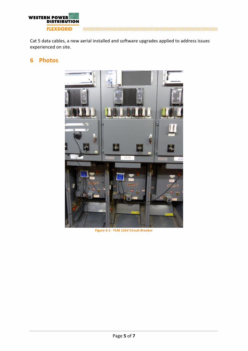
Figure 6-1 - FLM 11kV Circuit Breakers
Page 5 of 7

FLM Installation Report Hall Green
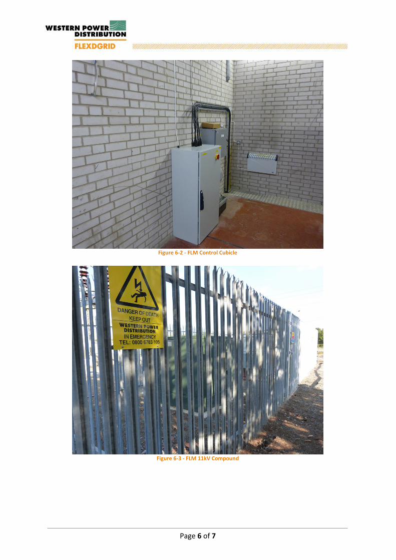
Figure 6-2 - FLM Control Cubicle
Figure 6-3 - FLM Control Cubicle (Internal)
Page 6 of 7


Page 1 of 1
SDRC-7 Installation and Open-Loop Tests of FLM Equipment
Appendix G – Elmdon Installation Report

FLM Installation Report Elmdon

FLM Installation Report Elmdon
Document Control
Name Date Prepared by: Paul Edwards 11.08.2015
Reviewed by: Jonathan Berry 19.11.2015
Approved (WPD): Jonathan Berry 19.11.2015
Revision History
Date Issue Status 11.08.2015 D01 Draft
19.11.2015 V01 FINAL
Report Title : FLM Installation Report, Elmdon
Report Status : Draft
Project Ref : WPDT2004 - FlexDGrid
Date : 19.11.2015
Page 2 of 7

FLM Installation Report Elmdon
1 Introduction The following report details the design, installation and commissioning of the Fault Level Monitor at Elmdon 132/11kV Substation. This was the first Fault Level Monitor commissioned as part of FlexDGrid. The report aims to disseminate information about the installation and commissioning of the FLM at this substation and the learning taken forward to the subsequent FLM installations. 2 Substation Overview Elmdon 132/11kV Substation is located in close proximity to the NEC Birmingham and only a short distance from Birmingham International Airport. The substation is supplied from Lea Marston 400/132kV GSP and consists of 1 no. 132/11kV 30 MVA transformer and 2 no. 132/11/11kV 60 MVA transformers supplying 7 no. sections of 11kV switchgear.
Figure 2-1 - Original Elmdon SLD
3 Connection and design The availability of a spare breaker on the existing 11kV switchboard was selected as the preferred HV connection method. The FLM was positioned inside the 132kV compound adjacent to the existing LV unit substation to minimise the operational impact and reduce the risk of hampering potential future removal/installation of transformers or 132kV equipment.
Figure 3-1 - SLD of FLM connection The FLM Control cabinet was positioned adjacent to the 11kV switchboard containing the FLM breaker to keep the length of the CT wiring to a minimum, reducing the effect of any wiring modifications on the existing protection circuits. This positioning also enabled the LV cable and fibre optic communications cable to easily enter the HV cable trench out to the
Page 3 of 7
FLM Installation Report Elmdon
FLM compound. The cables were designed to exit the substation at the rear of the 11kV substation building entering cable ducts that follow the perimeter of the substation building and into the 132kV compound before entering the FLM compound. 4 Installation The installation works on site began in July 2014 with commencement of the civil works, installing the foundations for the IntelliRupter and Resistor, installation of the new compound fence and cable ducts. During the works it was noted that the proposed methodology for the bending of the cables into the IntelliRupter HV cable box using ducts through the concrete foundation may present difficulties. A redesign of the base was carried out to replace the ducts with a “cut-out enabling the cables to be easily manipulated into place. This design was subsequently adopted for all future outdoor applications. The contractor installed the cables ready for termination and initially used an unarmoured fibre optic cable. This sustained rodent damage due to the type of UPVC that the fibres were wrapped in. This was replaced however further damage was sustained to the replacement prior to commissioning so a temporary cable was installed at high level on the substation compound fence until a suitable armoured cable could be installed. The electrical installation works began in September 2014 with an upgrade to the existing protection and termination of all cabling. 5 Commissioning The FLM was initially commissioned on the 14th October 2014. Once all the equipment was set up and fully connected the FLM was tested. As this was the first FLM installation for FlexDGrid, following commissioning several issues were identified. The first issue was that the data connection between the Envoy and PM7000s was not stable; meaning that after a period of time the communications link would drop out and require a manual restart. The other issue was that for the safety of the system the Envoy requires a constant communications link with the IntelliRupter and confirmation that the commands sent have been completed and a confirmation signal has been received. The way that the IntelliRupter responds to commands was not immediate causing the Envoy to stop operation believing that control of the IntelliRupter has been lost. The final issue was that the positioning of the control cabinet meant the built-in GPRS aerial was next to another wall mounted box causing the signal strength to be outside the optimum working range. It was proposed to install an external aerial in its place that would move aerial outside of the building in order to minimise interference from walls and other equipment. Following off site testing and work by suppliers the site was re-commissioned on the 13th November 2014 with an armoured fibre optic cable installed, USB data cables replaced by
Page 4 of 7
FLM Installation Report Elmdon
Cat 5 data cables, a new aerial installed and software upgrades applied to address issues experienced on site. 6 Photos
Figure 6-1 - FLM 11kV Circuit Breaker
Page 5 of 7
FLM Installation Report Elmdon
Figure 6-2 - FLM Control Cubicle
Figure 6-3 - FLM 11kV Compound
Page 6 of 7


Page 1 of 1
SDRC-7 Installation and Open-Loop Tests of FLM Equipment
Appendix H – Chad Valley Installation Report

FLM Installation Report Chad Valley
FLM Installation Report Chad Valley
Document Control
Name Date Prepared by: Paul Edwards 11.08.2015
Reviewed by: Jonathan Berry 19.11.2015
Approved (WPD): Jonathan Berry 19.11.2015
Revision History
Date Issue Status 11.08.2015 D01 Draft
19.11.2015 V01 FINAL
Report Title : FLM Installation Report, Chad Valley
Report Status : Draft
Project Ref : WPDT2004 - FlexDGrid
Date : 19.11.2015
Page 2 of 8

FLM Installation Report Chad Valley
1 Introduction The following report details the design, installation and commissioning of the Fault Level Monitor at Chad Valley 132/11kV Substation. This was the second Fault Level Monitor commissioned as part of FlexDGrid. The report aims to disseminate information about the installation and commissioning of the FLM at this substation and the learning taken forward to the subsequent FLM installations. 2 Substation Overview Chad Valley substation is located approximately 3.5km west of Birmingham City Centre. The substation is supplied by Kitwell 400/132kV GSP and consists of 2 no. 132/11/11kV transformers supplying 4 no. sections of 11kV switchgear.
Figure 2-1 - Original Chad Valley SLD
Page 3 of 8

FLM Installation Report Chad Valley
3 Connection and design The existing switchgear at Chad Valley is oil filled KN type, and due to its age, not deemed suitable for the connection of an FLM. Therefore it was proposed to install a new 2 panel switchboard and connect this to a spare circuit breaker on the existing switchboard.
Figure 3-1 - SLD of FLM connection
For the installation of the new switchboard the spare switchroom required complete refurbishment including a new floor and lighting. The switchgear selected was FKI Eclipse as the switchgear was to be installed over a large basement. The FLM control cabinet required inputs from the transformer circuit breakers at opposite corners of the 11kV switch house. To try and keep all the cable lengths to a minimum the cabinet was placed in a central location. The FLM at Chad Valley was located in a former transformer oil tank bay adjacent to the 132kV building. Due to the size of the site and the number of cable tunnels running between the 132 and 11kV buildings it was decided that the cost of reforming the existing foundations for the FLM was not cost effective. Therefore it was decided that the IntelliRupter and Resistor would be raised on a steel frame allowing all HV cables to be run underneath.
Page 4 of 8
FLM Installation Report Chad Valley
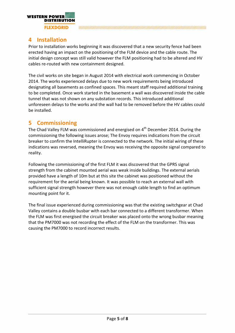
4 Installation Prior to installation works beginning it was discovered that a new security fence had been erected having an impact on the positioning of the FLM device and the cable route. The initial design concept was still valid however the FLM positioning had to be altered and HV cables re-routed with new containment designed. The civil works on site began in August 2014 with electrical work commencing in October 2014. The works experienced delays due to new work requirements being introduced designating all basements as confined spaces. This meant staff required additional training to be completed. Once work started in the basement a wall was discovered inside the cable tunnel that was not shown on any substation records. This introduced additional unforeseen delays to the works and the wall had to be removed before the HV cables could be installed. 5 Commissioning The Chad Valley FLM was commissioned and energised on 4th December 2014. During the commissioning the following issues arose; The Envoy requires indications from the circuit breaker to confirm the IntelliRupter is connected to the network. The initial wiring of these indications was reversed, meaning the Envoy was receiving the opposite signal compared to reality. Following the commissioning of the first FLM it was discovered that the GPRS signal strength from the cabinet mounted aerial was weak inside buildings. The external aerials provided have a length of 10m but at this site the cabinet was positioned without the requirement for the aerial being known. It was possible to reach an external wall with sufficient signal strength however there was not enough cable length to find an optimum mounting point for it. The final issue experienced during commissioning was that the existing switchgear at Chad Valley contains a double busbar with each bar connected to a different transformer. When the FLM was first energised the circuit breaker was placed onto the wrong busbar meaning that the PM7000 was not recording the effect of the FLM on the transformer. This was causing the PM7000 to record incorrect results.
Page 5 of 8

FLM Installation Report Chad Valley
6 Photos
Figure 6-1 - FLM Control Cubicle (Internal)
1 Figure 6-2 - FLM 11kV Circuit Breakers
Page 6 of 8

FLM Installation Report Chad Valley
Figure 6-3 - FLM 11kV Compound
Figure 6-4 - FLM 11kV Compound Access
Page 7 of 8

Page 1 of 1
SDRC-7 Installation and Open-Loop Tests of FLM Equipment
Appendix I – Shirley Installation Report

FLM Installation Report Shirley

FLM Installation Report Shirley
Document Control
Name Date Prepared by: Paul Edwards 02.10.2015
Reviewed by: Jonathan Berry 19.11.2015
Approved (WPD): Jonathan Berry 19.11.2015
Revision History
Date Issue Status 02.10.2015 D01 Draft
19.11.2015 V01 FINAL
Report Title : FLM Installation Report Shirley
Report Status : FINAL
Project Ref : WPDT2004 - FlexDGrid
Date : 19.11.2015
Page 2 of 6
FLM Installation Report Shirley
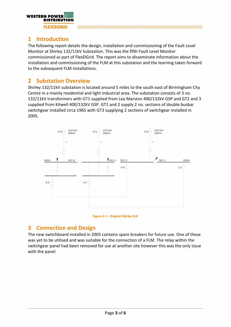
1 Introduction The following report details the design, installation and commissioning of the Fault Level Monitor at Shirley 132/11kV Substation. This was the fifth Fault Level Monitor commissioned as part of FlexDGrid. The report aims to disseminate information about the installation and commissioning of the FLM at this substation and the learning taken forward to the subsequent FLM installations. 2 Substation Overview Shirley 132/11kV substation is located around 5 miles to the south east of Birmingham City Centre in a mainly residential and light industrial area. The substation consists of 3 no. 132/11kV transformers with GT1 supplied from Lea Marston 400/132kV GSP and GT2 and 3 supplied from Kitwell 400/132kV GSP. GT1 and 2 supply 2 no. sections of double busbar switchgear installed circa 1965 with GT3 supplying 2 sections of switchgear installed in 2005.
SEC D SEC CSEC B SEC A
A-C
D-B
2000A1600A
B-D
C-A
GT1 132/11kV30MVA
VT
GT2 132/11kV30MVA
VT
GT3 132/11kV30MVA
VT
Figure 2-1 - Original Shirley SLD
3 Connection and Design The new switchboard installed in 2005 contains spare breakers for future use. One of these was yet to be utilised and was suitable for the connection of a FLM. The relay within the switchgear panel had been removed for use at another site however this was the only issue with the panel.
Page 3 of 6

FLM Installation Report Shirley
SEC D SEC CSEC B SEC A
FLM
FLM630A
A-C
D-B
2000A1600A
B-D
C-A
GT1 132/11kV30MVA
VT
GT2 132/11kV30MVA
VT
GT3 132/11kV30MVA
VT
Figure 3-1 - SLD of FLM Connection
The positioning of the FLM compound was restricted due to the positioning of the 11kV feeder cables and a 132kV overhead line. Following a ground radar survey a suitable area that avoided lifting operations near the overhead line and with minimal requirement for cable diversions was selected. The FLM compound arrangement enabled the cables to enter the cable between the IntelliRupter and Resister. This would lead to an easier installation as the foundations would not require any ducts running underneath them. 4 Installation At the start of installation the team on site suggested a potential move of the FLM compound to a new location next to the 11kV switchroom, underneath the 132kV overhead line. The onsite SAP decided that the risk of installation under the OHL was negligible and the height of the lift could be managed so as not to be an issue. This installation reduced the length of the cable installation but required a deeper cable trench as the distance between the switchroom and compound is not long enough for the cables to be brought upto a shallower depth before termination into the FLM equipment. 5 Commissioning The site was commissioned in March 2015. The commissioning was extremely smooth with no issues identified at the time. However, once the system had settled, the Fault Level results being recorded were not consistent. This was initially attributed to an incorrect CT gain settings within the PM7000 that the supplier identified following their review of commissioning notes. This however did not solve the issue and the equipment supplier believed this was being caused by the characteristics of the site. After a period of time further investigations were carried out into the current waveforms being recorded and it showed that the CT on the blue phase was reversed. Once the CT was reversed the results became consistent and in-line with the results being produced from other sites. Page 4 of 6
FLM Installation Report Shirley
6 Photos
Figure 6-1 - FLM Control Cubicle
Figure 6-2 - FLM 11kV Compound
Page 5 of 6

Page 1 of 1
SDRC-7 Installation and Open-Loop Tests of FLM Equipment
Appendix J – Nechells West Installation Report

FLM Installation Report Nechells West

FLM Installation Report Nechells West
Document Control
Name Date Prepared by: Paul Edwards 02.10.2015
Reviewed by: Jonathan Berry 19.11.2015
Approved (WPD): Jonathan Berry 19.11.2015
Revision History
Date Issue Status 02.10.2015 D01 Draft
19.11.2015 V01 FINAL
Report Title : FLM Installation Report Nechells West
Report Status : FINAL
Project Ref : WPDT2004 - FlexDGrid
Date : 19.11.2015
Page 2 of 6

FLM Installation Report Nechells West
1 Introduction The following report details the design, installation and commissioning of the Fault Level Monitor at Nechells West 132/11kV Substation. This was the seventh Fault Level Monitor commissioned as part of FlexDGrid. The report aims to disseminate information about the installation and commissioning of the FLM at this substation and the learning taken forward to the subsequent FLM installations. 2 Substation Overview Nechells West Substation is located around 2 miles to the North of Birmingham City Centre adjacent to a large leisure complex and industrial area. The substation is fed from Nechells East 400/132kV GSP and consists of 3 no. 132/11/11kV transformers supplying 7 no. sections of 11kV switchgear. The substation was original commissioned circa 1969 and underwent 11kV replacement works in 2003.
Figure 2-1 - Original Nechells West SLD
Page 3 of 6
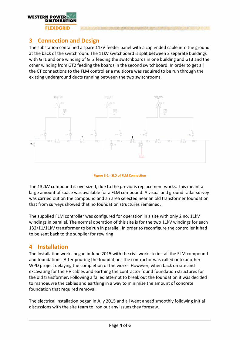
FLM Installation Report Nechells West
3 Connection and Design The substation contained a spare 11kV feeder panel with a cap ended cable into the ground at the back of the switchroom. The 11kV switchboard is split between 2 separate buildings with GT1 and one winding of GT2 feeding the switchboards in one building and GT3 and the other winding from GT2 feeding the boards in the second switchboard. In order to get all the CT connections to the FLM controller a multicore was required to be run through the existing underground ducts running between the two switchrooms.
Figure 3-1 - SLD of FLM Connection The 132kV compound is oversized, due to the previous replacement works. This meant a large amount of space was available for a FLM compound. A visual and ground radar survey was carried out on the compound and an area selected near an old transformer foundation that from surveys showed that no foundation structures remained. The supplied FLM controller was configured for operation in a site with only 2 no. 11kV windings in parallel. The normal operation of this site is for the two 11kV windings for each 132/11/11kV transformer to be run in parallel. In order to reconfigure the controller it had to be sent back to the supplier for rewiring 4 Installation The Installation works began in June 2015 with the civil works to install the FLM compound and foundations. After pouring the foundations the contractor was called onto another WPD project delaying the completion of the works. However, when back on site and excavating for the HV cables and earthing the contractor found foundation structures for the old transformer. Following a failed attempt to break out the foundation it was decided to manoeuvre the cables and earthing in a way to minimise the amount of concrete foundation that required removal. The electrical installation began in July 2015 and all went ahead smoothly following initial discussions with the site team to iron out any issues they foresaw. Page 4 of 6

FLM Installation Report Nechells West
5 Commissioning The commissioning of the site was carried out in August 2015. The process on the day went smoothly with no issues identified by the supplier. However following the commissioning day, it was identified that the wiring on inputs to the CTs was incorrect. Due to the large secondary currents two CTs were required to be connected in series. Due to a miss communication during the redesign of the cabinet, the measurement CTs were wired up incorrectly and though this was identified on site during the commissioning it was not corrected. This meant the currents being recorded by the measurement devices were too high. A further visit to site was carried out to correct the wiring and to ensure that all recorded currents were as expected. 6 Photos
Figure 6-1 - FLM 11kV Circuit Breaker
Figure 6-2 - FLM 11kV Compound
Page 5 of 6


![?a^SdRc ;XbcX]V](https://static.fdocuments.us/doc/165x107/588efea21a28ab84438b5b70/asdrc-xbcxv.jpg)


