Sdp Lte Sooka Kl Sentral v1.0
38
CELCOM LTE PROJECT Site Name: Loc ID: Date: Page: Sooka Sentral W00651 04 th June 2013 Page 1 of 32 In‐Building Site Survey Report Building: Sooka Sentral, Kuala Lumpur. Proposal v1.0
-
Upload
gio-zakradze -
Category
Documents
-
view
33 -
download
0
description
Sdp Lte Sooka Kl Sentral v1.0
Transcript of Sdp Lte Sooka Kl Sentral v1.0

CELCOM LTE PROJECT
Site Name: Loc ID: Date: Page: Sooka Sentral W00651 04th June 2013 Page 1 of 32
In‐Building Site Survey Report
Building: Sooka Sentral, Kuala Lumpur.
Proposal v1.0

CELCOM LTE PROJECT
Site Name: Loc ID: Date: Page: Sooka Sentral W00651 04th June 2013 Page 2 of 32
TABLE OF CONTENTS
1. SITE IDENTIFICATION INFORMATION
1.1 ACCESS ROUTE TO SITE
1.2 ACCESS TO EQUIPMENT ROOM
2. COVERAGE AREA
2.1 PROPOSED COVERAGE AREA
3. SITE DESIGN
3.1 EQUIPMENT ROOM LAYOUTS
3.2 OVERALL SYSTEM
3.3 SYSTEM MODULE
3.4 RF MODULE
3.5 ANTENNA LOCATION (PHOTO)
3.6 PROPOSED ANTENNA LOCATION (FLOOR PLAN)
3.7 COMBINING CIRCUIT
3.8 COMBINING CIRCUIT (IF APPLICABLE)

CELCOM LTE PROJECT
Site Name: Loc ID: Date: Page: Sooka Sentral W00651 04th June 2013 Page 3 of 32
1. SITE IDENTIFICATION INFORMATION
Customer Name: Celcom Complete Site Address:
Location ID: W00651 Sooka Sentral,
2G Site ID: Jalan Stesen Sentral 5
3G Site ID: 50470 Kuala Lumpur
BSC ID: Stesen Sentral Kuala Lumpur
Site Survey Date: 31st May 2013
ACCESS ROUTE TO SITE
Latitude/Longitude: 3° 08’ 00.99""N / 101° 41’ 06.56"E
Site Survey Team: Mohd Jeffry Shariff
Verified by: Muhammad Najwan B Sidi Omar
Checked by: ____________________
Celcom
CELCOM LTE PROJECT
Site Name: Loc ID: Date: Page: Sooka Sentral W00651 04th June 2013 Page 4 of 32
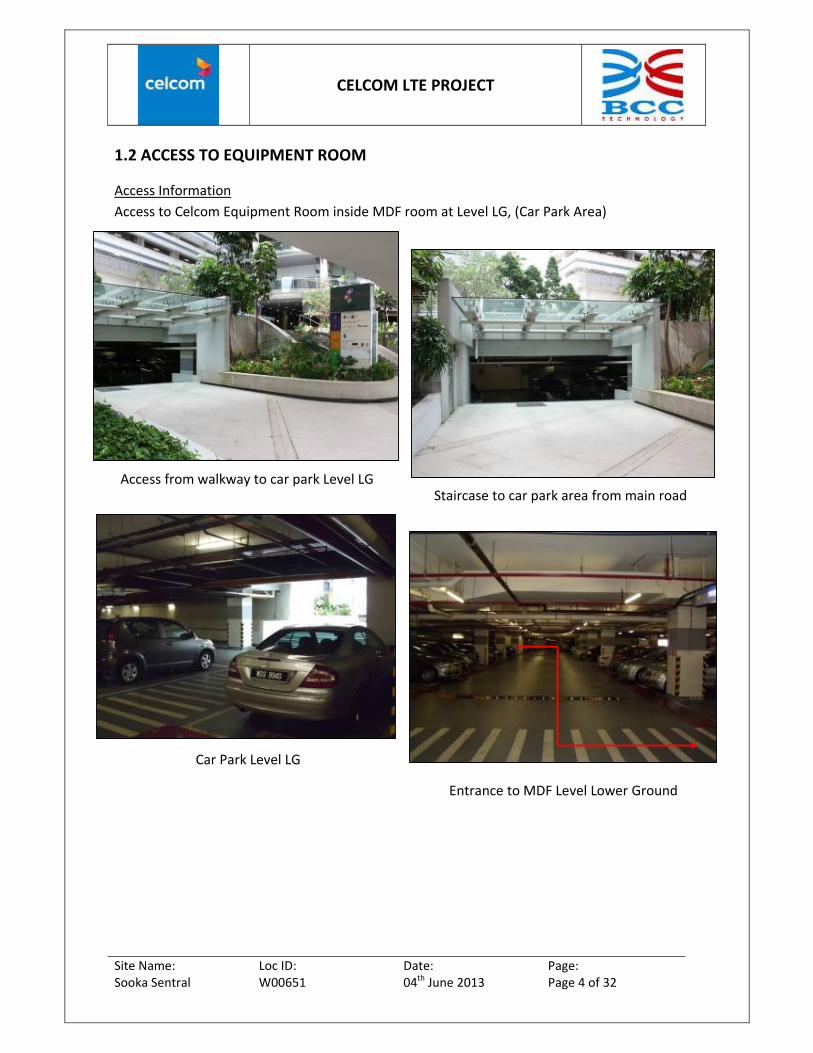
1.2 ACCESS TO EQUIPMENT ROOM
Access Information
Access to Celcom Equipment Room inside MDF room at Level LG, (Car Park Area)
Access from walkway to car park Level LGStaircase to car park area from main road
Car Park Level LG
Entrance to MDF Level Lower Ground

CELCOM LTE PROJECT
Site Name: Loc ID: Date: Page: Sooka Sentral W00651 04th June 2013 Page 5 of 32
Car Park Level Lower Ground
Celcom equipment room inside MDF room
MDF Room door access Level LG
Entrance
CELCOM LTE PROJECT
Site Name: Loc ID: Date: Page: Sooka Sentral W00651 04th June 2013 Page 6 of 32
2. COVERAGE AREA
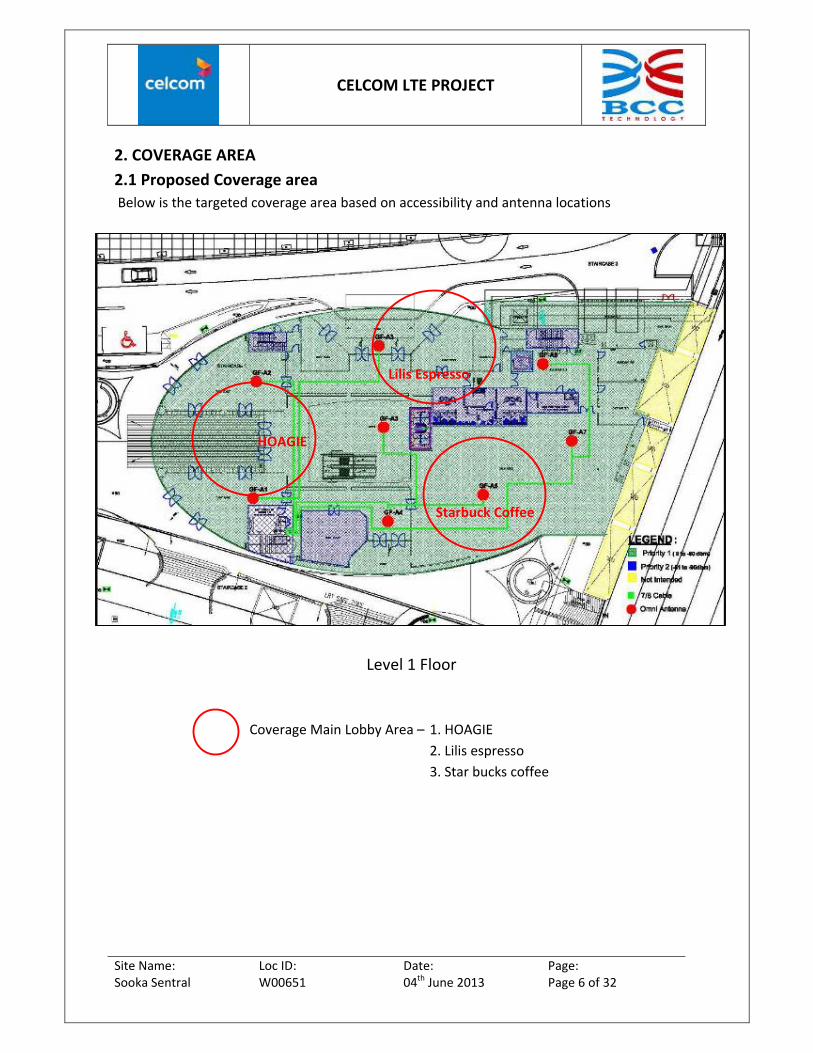
2.1 Proposed Coverage area
Below is the targeted coverage area based on accessibility and antenna locations
Level 1 Floor
Coverage Main Lobby Area – 1. HOAGIE
2. Lilis espresso
3. Star bucks coffee
HOAGIE
Starbuck Coffee
Lilis Espresso

CELCOM LTE PROJECT
Site Name: Loc ID: Date: Page: Sooka Sentral W00651 04th June 2013 Page 7 of 32
Level 2 Floors
Coverage Area – 1. Kelantan Delight
2. Restaurant Area
3. Meals Station
Kelantan Delight
Restaurant Area
Meals Station
CELCOM LTE PROJECT
Site Name: Loc ID: Date: Page: Sooka Sentral W00651 04th June 2013 Page 8 of 32
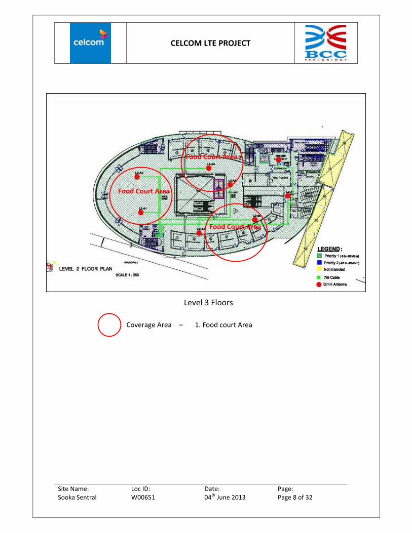
Level 3 Floors
Coverage Area – 1. Food court Area
Food Court Area
Food Court Area
Food Court Area

CELCOM LTE PROJECT
Site Name: Loc ID: Date: Page: Sooka Sentral W00651 04th June 2013 Page 9 of 32
3. SITE DESIGN
3.1 EQUIPMENT ROOM
Existing celcom equipment inside MDF Room
Level Lower Ground
Door Access from parking lot. Get key from
MRCB Technical department
CELCOM LTE PROJECT
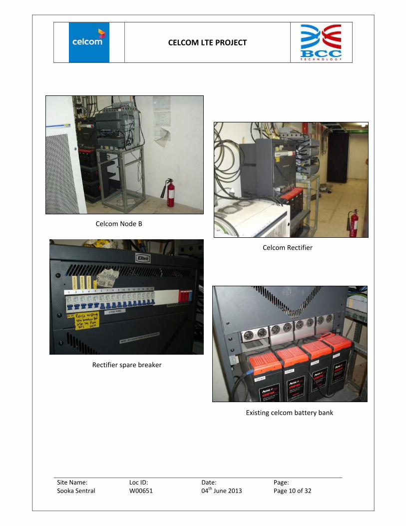
Site Name: Loc ID: Date: Page: Sooka Sentral W00651 04th June 2013 Page 10 of 32
Celcom Node B
Celcom Rectifier
Existing celcom battery bank
Rectifier spare breaker

CELCOM LTE PROJECT
Site Name: Loc ID: Date: Page: Sooka Sentral W00651 04th June 2013 Page 11 of 32
3.2 OVERALL SYSTEM
For System 1:
Power Cable Length : 15 m
Grounding Cable Length : 30 m
Transmission Length : 20m
Transmission Type : CAT‐5E
Antenna Label Antenna Type Remark
CLCM‐LTESys1‐Sec1‐1 Omni Locate at ceiling Main Lobby Area
CLCM‐LTESys1‐Sec1‐2 Omni Locate at ceiling Main Lobby Area
CLCM‐LTESys1‐Sec1‐3 Omni Locate at ceiling opposite Lilis espressor
CLCM‐LTESys1‐Sec1‐4 Omni Locate at ceiling opposite Lilis espressor
CLCM‐LTESys1‐Sec1‐5 Omni Locate at ceiling beside star bucks coffe
CLCM‐LTESys1‐Sec1‐6 Omni Locate at ceiling beside star bucks coffe
CLCM‐LTESys1‐Sec2‐1 Omni Locate at ceiling opposite Kelantan Delight
CLCM‐LTESys1‐Sec2‐2 Omni Locate at ceiling opposite Kelantan Delight
CLCM‐LTESys1‐Sec2‐3 Omni Locate at ceiling opposite restaurant
CLCM‐LTESys1‐Sec2‐4 Omni Locate at ceiling opposite restaurant
CLCM‐LTESys1‐Sec2‐5 Omni Locate at ceiling opposite meal station
CLCM‐LTESys1‐Sec2‐6 Omni Locate at ceiling opposite meal station
CLCM‐LTESys1‐Sec3‐1 Omni Locate at ceiling inside food court
CLCM‐LTESys1‐Sec3‐2 Omni Locate at ceiling inside food court
CLCM‐LTESys1‐Sec3‐3 Omni Locate at ceiling inside food court
CLCM‐LTESys1‐Sec3‐4 Omni Locate at ceiling inside food court
CLCM‐LTESys1‐Sec3‐5 Omni Locate at ceiling inside food court counter
CLCM‐LTESys1‐Sec3‐6 Omni Locate at ceiling inside food court counter

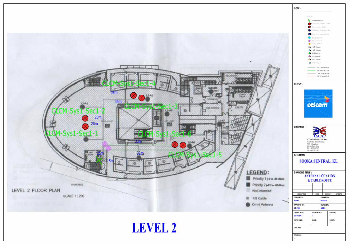
LEVEL 2
default 0.06
20 m 22.5 25.5 CLCM-Sys1-Sec3-1
default 0.06
20 m 22.5default 0.06 25.5 CLCM-Sys1-Sec3-228.9 23.9
15 m default 0.06
35 m 21.5 24.5 CLCM-Sys1-Sec3-3
default 0.06
35 m 21.5default 0.06 24.5 CLCM-Sys1-Sec3-4
30 dBm 28.9 23.915 m
120 m default 0.06
33 m 21.624.6 CLCM-Sys1-Sec3-5
default 0.06
33 m 21.624.6 CLCM-Sys1-Sec3-6
LEVEL 1
default 0.06
15 m 22.8 25.8 CLCM-Sys1-Sec2-1
default 0.06
15 m 22.8default 0.06 25.8 CLCM-Sys1-Sec2-228.9 23.9
15 mdefault 0.06
18 m 22.6 25.6 CLCM-Sys1-Sec2-3
default 0.06
18 m 22.6default 0.06 25.6 CLCM-Sys1-Sec2-4
30 dBm 28.9 23.915 m
100 m default 0.06
45 m 20.9 23.9 CLCM-Sys1-Sec2-5
default 0.06
45 m 20.9 23.9 CLCM-Sys1-Sec2-6
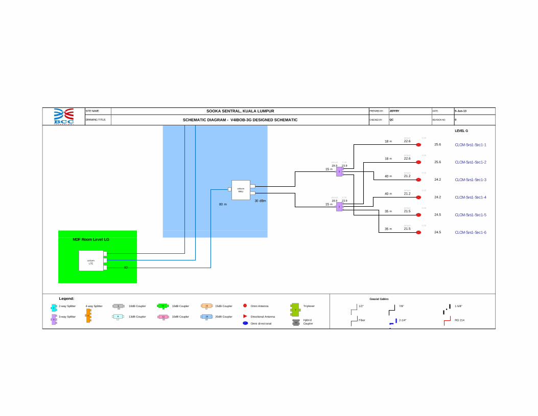
SOOKA SENTRAL, KUALA LUMPURSITE NAME:
DRAWING TITLE: SCHEMATIC DIAGRAM - V4IBOB-3G DESIGNED SCHEMATIC
5-Jun-13
CHECKED BY: QC REVISION NO: 0
JEFFRY DATE:PREPARED BY:
33
33
celcomRRU
33
33
celcomRRU
SOOKA SENTRAL, KUALA LUMPURSITE NAME:
DRAWING TITLE: SCHEMATIC DIAGRAM - V4IBOB-3G DESIGNED SCHEMATIC
5-Jun-13
CHECKED BY: QC REVISION NO: 0
JEFFRY DATE:PREPARED BY:
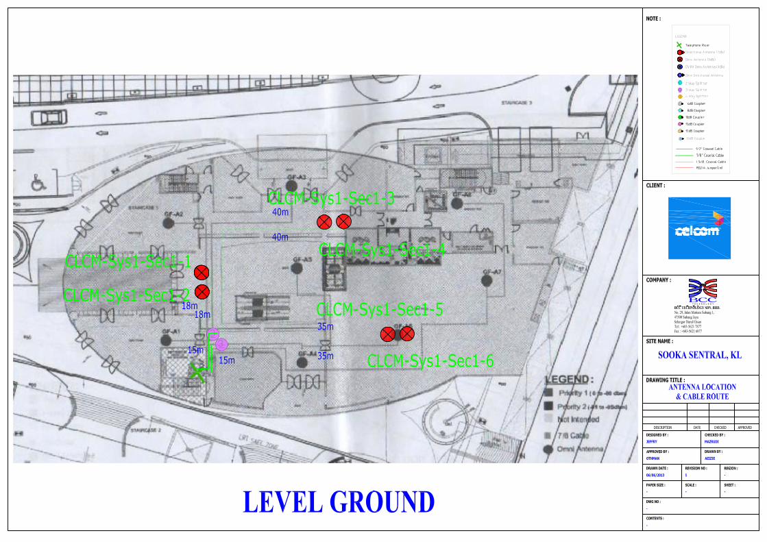
LEVEL G
default 0.06
18 m 22.6 25.6 CLCM-Sys1-Sec1-1
default 0.06
18 m 22.6default 0.06 25.6 CLCM-Sys1-Sec1-2
28.9 23.9 15 m
default 0.06
40 m 21.2 24.2 CLCM-Sys1-Sec1-3
default 0.06
40 m 21.2default 0.06 24.2 CLCM-Sys1-Sec1-4
30 dBm 28.9 23.980 m 15 m
default 0.06
35 m 21.524.5 CLCM-Sys1-Sec1-5
default 0.06
35 m 21.5 24.5 CLCM-Sys1-Sec1-6
MDF Room Level LG
60
Legend: Coaxial Cables
2-way Splitter 4-way Splitter 10dB Coupler 10dB Coupler 15dB Coupler Omni Antenna Triplexer 1/2" 7/8" 1-5/8"
3-way Splitter 13dB Coupler 10dB Coupler 20dB Coupler Directional AntennaHybrid Fiber 2-1/4" RG 214
Omni directional Coupler
26
4
3
8 20
15
13
10
T
H
33
33
celcomRRU
celcom
LTE
CELCOM LTE PROJECT
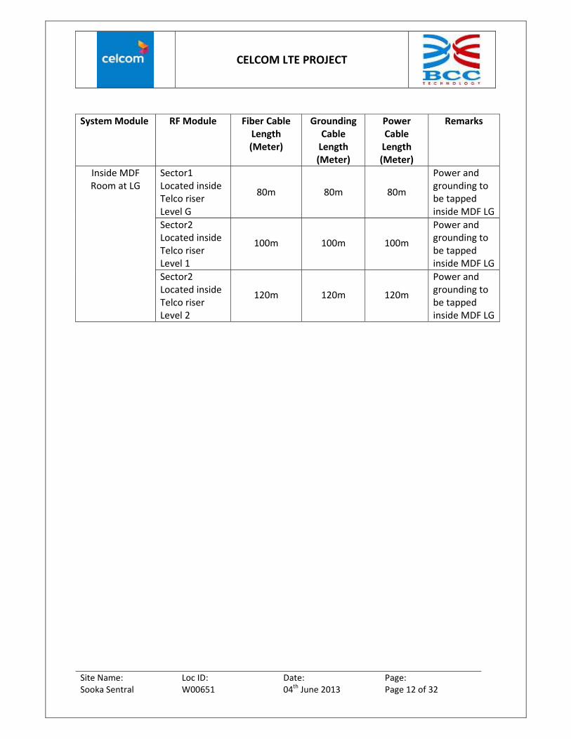
Site Name: Loc ID: Date: Page: Sooka Sentral W00651 04th June 2013 Page 12 of 32
System Module RF Module Fiber Cable Length (Meter)
Grounding Cable Length (Meter)
Power Cable Length (Meter)
Remarks
Sector1 Located inside Telco riser Level G
80m 80m 80m
Power and grounding to be tapped inside MDF LG
Sector2 Located inside Telco riser Level 1
100m 100m 100m
Power and grounding to be tapped inside MDF LG
Inside MDF Room at LG
Sector2 Located inside Telco riser Level 2
120m 120m 120m
Power and grounding to be tapped inside MDF LG
CELCOM LTE PROJECT
Site Name: Loc ID: Date: Page: Sooka Sentral W00651 04th June 2013 Page 13 of 32
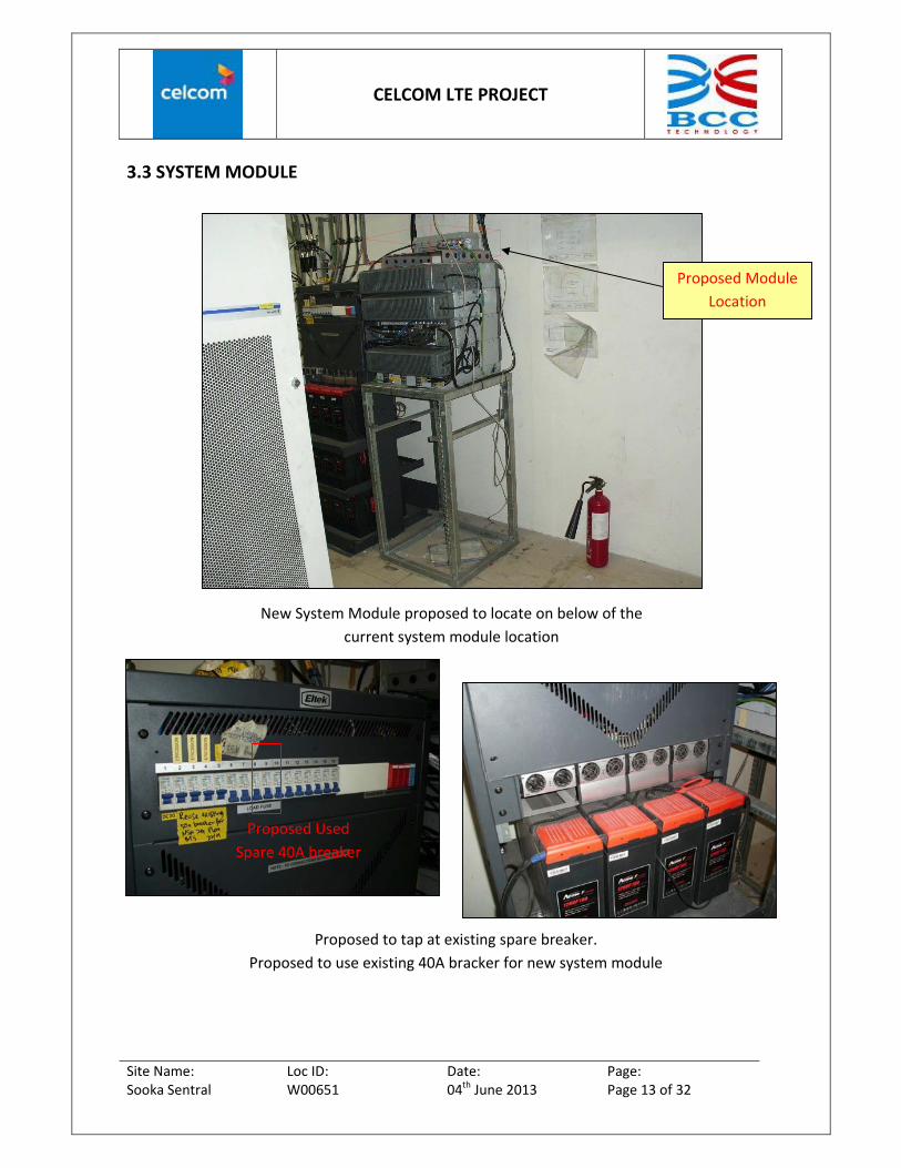
3.3 SYSTEM MODULE
Proposed to tap at existing spare breaker.
Proposed to use existing 40A bracker for new system module
New System Module proposed to locate on below of the
current system module location
Proposed Module
Location
Proposed Used
Spare 40A breaker

CELCOM LTE PROJECT
Site Name: Loc ID: Date: Page: Sooka Sentral W00651 04th June 2013 Page 14 of 32
TRANSMISSION SYSTEM
Existing Celcom 19’’ Rack
Existing celcom transmission patching system
CELCOM LTE PROJECT
Site Name: Loc ID: Date: Page: Sooka Sentral W00651 04th June 2013 Page 15 of 32
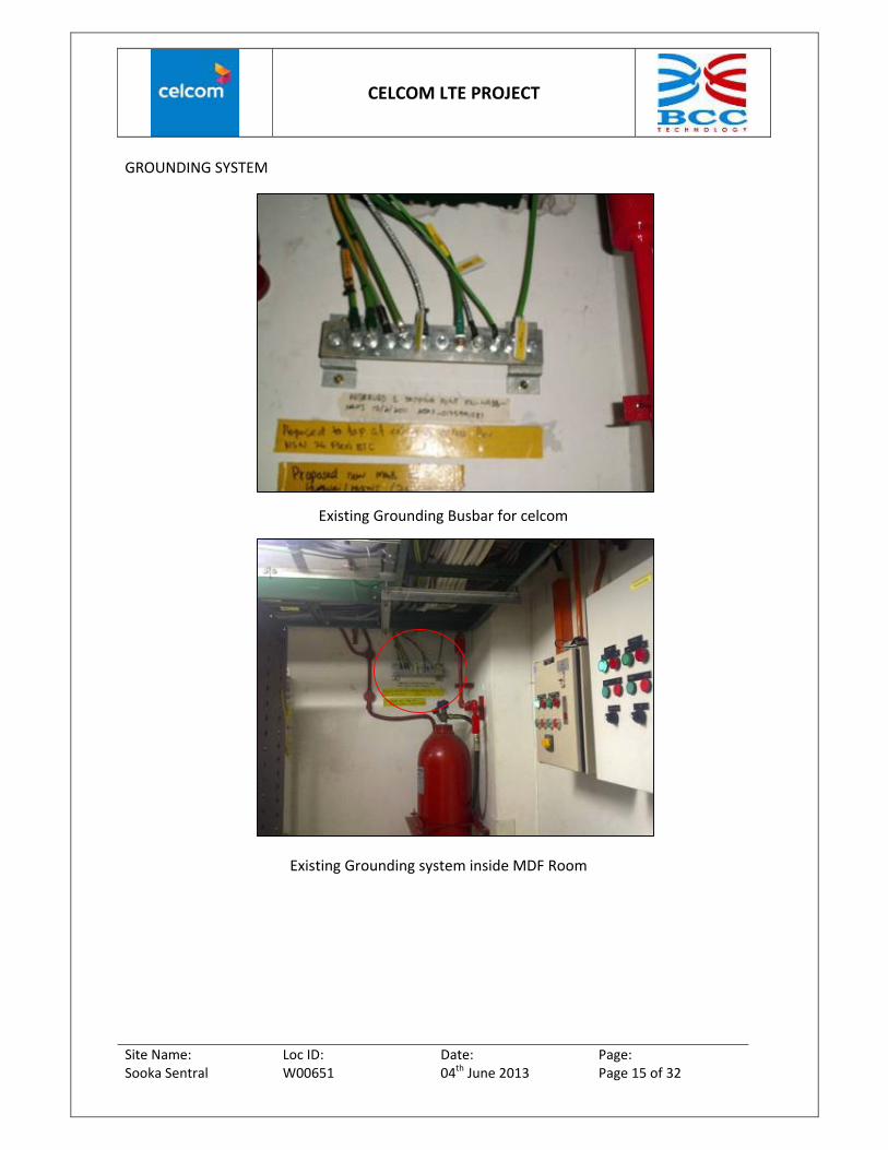
GROUNDING SYSTEM
Existing Grounding system inside MDF Room
Existing Grounding Busbar for celcom

CELCOM LTE PROJECT
Site Name: Loc ID: Date: Page: Sooka Sentral W00651 04th June 2013 Page 16 of 32
EQUIPMENT LAYOUT SYSTEM
Celcom layout inside MDF Room level Lower Ground
Existing Celcom
Equipment
Existing Celcom
Rectifier

CELCOM LTE PROJECT
Site Name: Loc ID: Date: Page: Sooka Sentral W00651 04th June 2013 Page 17 of 32
3.4 RF MODULE
Sector 1 2 & 3 RF Module with Fibres Route (Side View)

CELCOM LTE PROJECT
Site Name: Loc ID: Date: Page: Sooka Sentral W00651 04th June 2013 Page 18 of 32
Proposed RF module sector 1 inside telephone riser Level G
Sec 1
RF Module
Proposed RF module sec 1 inside
Telephone riser Level G
Proposed RF module with wall mounted structure

CELCOM LTE PROJECT
Site Name: Loc ID: Date: Page: Sooka Sentral W00651 04th June 2013 Page 19 of 32
Proposed RF module sector 2 inside telephone riser Level 1
Sec 2
RF Module
Proposed RF module with wall mounted structure
Proposed RF module sec 2 inside
Telephone riser Level 1

CELCOM LTE PROJECT
Site Name: Loc ID: Date: Page: Sooka Sentral W00651 04th June 2013 Page 20 of 32
Proposed RF module sector 3 inside telephone riser Level 2
Proposed RF module sec 3 inside
Telephone riser Level 1
Proposed RF module with wall mounted structure
Sec 3
RF Module

CELCOM LTE PROJECT
Site Name: Loc ID: Date: Page: Sooka Sentral W00651 04th June 2013 Page 21 of 32
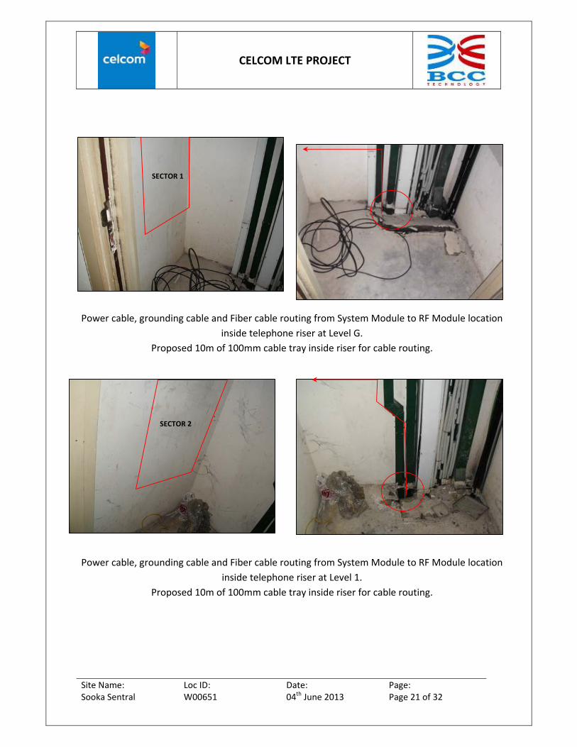
Power cable, grounding cable and Fiber cable routing from System Module to RF Module location
inside telephone riser at Level G.
Proposed 10m of 100mm cable tray inside riser for cable routing.
Power cable, grounding cable and Fiber cable routing from System Module to RF Module location
inside telephone riser at Level 1.
Proposed 10m of 100mm cable tray inside riser for cable routing.
SECTOR 1
SECTOR 2

CELCOM LTE PROJECT
Site Name: Loc ID: Date: Page: Sooka Sentral W00651 04th June 2013 Page 22 of 32
Power cable, grounding cable and Fiber cable routing from System Module to RF Module location
inside telephone riser at Level 2.
Proposed 10m of 100mm cable tray inside riser for cable routing.
SECTOR 3
CELCOM LTE PROJECT
Site Name: Loc ID: Date: Page: Sooka Sentral W00651 04th June 2013 Page 23 of 32
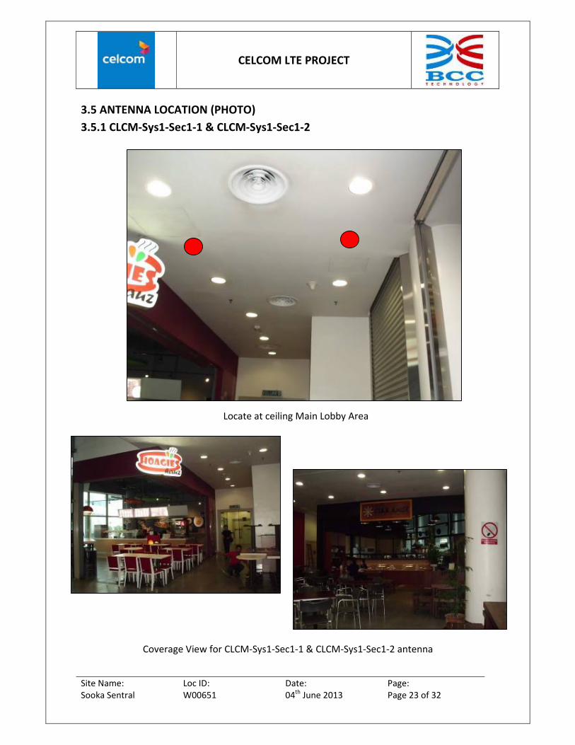
3.5 ANTENNA LOCATION (PHOTO)
3.5.1 CLCM‐Sys1‐Sec1‐1 & CLCM‐Sys1‐Sec1‐2
Coverage View for CLCM‐Sys1‐Sec1‐1 & CLCM‐Sys1‐Sec1‐2 antenna
Locate at ceiling Main Lobby Area

CELCOM LTE PROJECT
Site Name: Loc ID: Date: Page: Sooka Sentral W00651 04th June 2013 Page 24 of 32
3.5.2 CLCM‐Sys1‐Sec1‐3 & CLCM‐Sys1‐Sec1‐4
Locate at ceiling opposite Lilis espresso
Coverage View for CLCM‐Sys1‐Sec1‐3 & CLCM‐Sys1‐Sec1‐4 antenna
CELCOM LTE PROJECT
Site Name: Loc ID: Date: Page: Sooka Sentral W00651 04th June 2013 Page 25 of 32
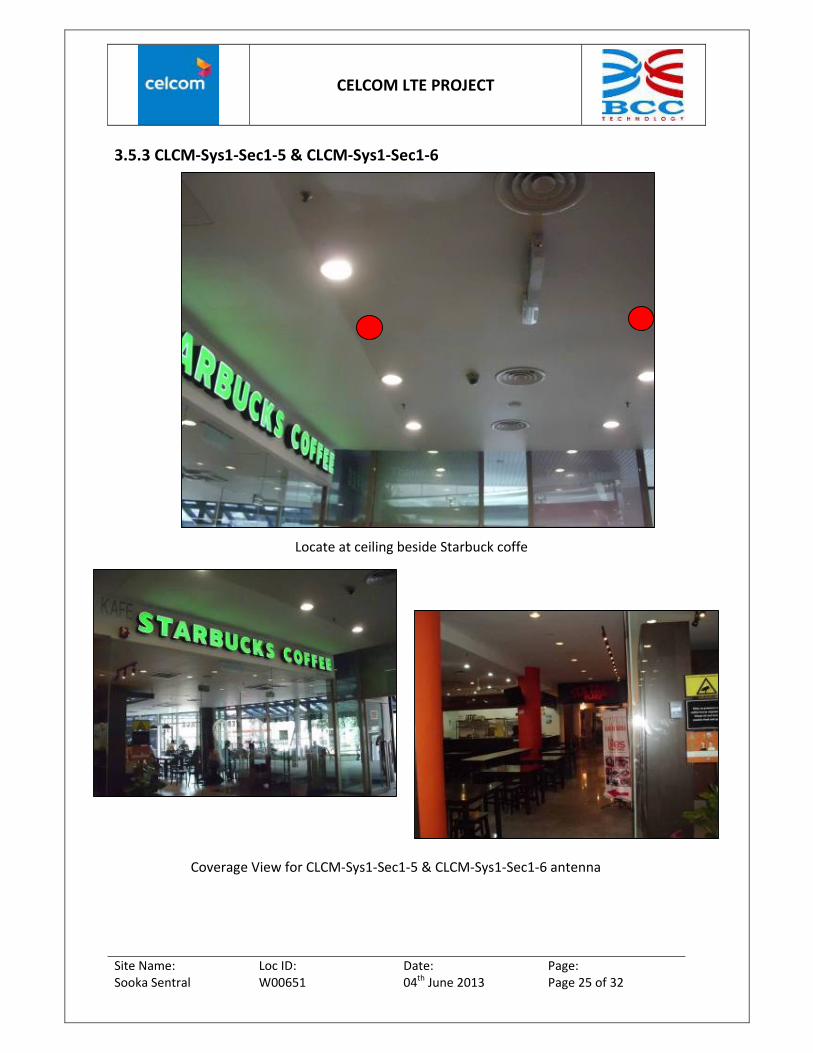
3.5.3 CLCM‐Sys1‐Sec1‐5 & CLCM‐Sys1‐Sec1‐6
Locate at ceiling beside Starbuck coffe
Coverage View for CLCM‐Sys1‐Sec1‐5 & CLCM‐Sys1‐Sec1‐6 antenna

CELCOM LTE PROJECT
Site Name: Loc ID: Date: Page: Sooka Sentral W00651 04th June 2013 Page 26 of 32
3.5.4 CLCM‐Sys1‐Sec2‐1 & CLCM‐Sys1‐Sec2‐2
Locate at ceiling opposite Kelantan delight
Coverage View for CLCM‐Sys1‐Sec2‐1 & CLCM‐Sys1‐Sec2‐2 antenna

CELCOM LTE PROJECT
Site Name: Loc ID: Date: Page: Sooka Sentral W00651 04th June 2013 Page 27 of 32
3.5.5 CLCM‐Sys1‐Sec2‐3 & CLCM‐Sys1‐Sec1‐4
Locate at ceiling opposite Restaurant
Coverage View for CLCM‐Sys1‐Sec2‐3 & CLCM‐Sys1‐Sec2‐4 antenna

CELCOM LTE PROJECT
Site Name: Loc ID: Date: Page: Sooka Sentral W00651 04th June 2013 Page 28 of 32
3.5.6 CLCM‐Sys1‐Sec2‐5 & CLCM‐Sys1‐Sec2‐6
Locate at ceiling opposite Meals Station
Coverage View for CLCM‐Sys1‐Sec2‐5 & CLCM‐Sys1‐Sec2‐6 antenna

CELCOM LTE PROJECT
Site Name: Loc ID: Date: Page: Sooka Sentral W00651 04th June 2013 Page 29 of 32
3.5.7 CLCM‐Sys1‐Sec3‐1 & CLCM‐Sys1‐Sec3‐2
Locate at ceiling at Food court
Coverage View for CLCM‐Sys1‐Sec3‐1 & CLCM‐Sys1‐Sec3‐2 antenna
CELCOM LTE PROJECT
Site Name: Loc ID: Date: Page: Sooka Sentral W00651 04th June 2013 Page 30 of 32
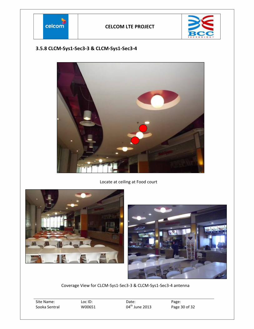
3.5.8 CLCM‐Sys1‐Sec3‐3 & CLCM‐Sys1‐Sec3‐4
Locate at ceiling at Food court
Coverage View for CLCM‐Sys1‐Sec3‐3 & CLCM‐Sys1‐Sec3‐4 antenna

CELCOM LTE PROJECT
Site Name: Loc ID: Date: Page: Sooka Sentral W00651 04th June 2013 Page 31 of 32
3.5.8 CLCM‐Sys1‐Sec3‐5 & CLCM‐Sys1‐Sec3‐6
Locate at ceiling at Food court
Coverage View for CLCM‐Sys1‐Sec3‐5 & CLCM‐Sys1‐Sec3‐6 antenna

CELCOM LTE PROJECT
Site Name: Loc ID: Date: Page: Sooka Sentral W00651 04th June 2013 Page 32 of 32
3.6 PROPOSED ANTENNA LOCATION (FLOOR PLAN)