SDM-CD8S 8 Channel Solid State DC Control Module1 SDM-CD8S 8 Channel Solid State DC Control Module...
32
SDM-CD8S 8 Channel Solid State DC Control Module User Manual Issued 11.6.12 Copyright © 2009-2012 Campbell Scientific Inc. Printed under licence by Campbell Scientific Ltd. CSL 800
Transcript of SDM-CD8S 8 Channel Solid State DC Control Module1 SDM-CD8S 8 Channel Solid State DC Control Module...

SDM-CD8S 8 Channel Solid State
DC Control Module
User Manual
Issued 11.6.12
Copyright © 2009-2012 Campbell Scientific Inc. Printed under licence by Campbell Scientific Ltd.
CSL 800


Guarantee This equipment is guaranteed against defects in materials and workmanship. This guarantee applies for twelve months from date of delivery. We will repair or replace products which prove to be defective during the guarantee period provided they are returned to us prepaid. The guarantee will not apply to:
• Equipment which has been modified or altered in any way without the written permission of Campbell Scientific
• Batteries
• Any product which has been subjected to misuse, neglect, acts of God or damage in transit.
Campbell Scientific will return guaranteed equipment by surface carrier prepaid. Campbell Scientific will not reimburse the claimant for costs incurred in removing and/or reinstalling equipment. This guarantee and the Company’s obligation thereunder is in lieu of all other guarantees, expressed or implied, including those of suitability and fitness for a particular purpose. Campbell Scientific is not liable for consequential damage.
Please inform us before returning equipment and obtain a Repair Reference Number whether the repair is under guarantee or not. Please state the faults as clearly as possible, and if the product is out of the guarantee period it should be accompanied by a purchase order. Quotations for repairs can be given on request. It is the policy of Campbell Scientific to protect the health of its employees and provide a safe working environment, in support of this policy a “Declaration of Hazardous Material and Decontamination” form will be issued for completion.
When returning equipment, the Repair Reference Number must be clearly marked on the outside of the package. Complete the “Declaration of Hazardous Material and Decontamination” form and ensure a completed copy is returned with your goods. Please note your Repair may not be processed if you do not include a copy of this form and Campbell Scientific Ltd reserves the right to return goods at the customers’ expense.
Note that goods sent air freight are subject to Customs clearance fees which Campbell Scientific will charge to customers. In many cases, these charges are greater than the cost of the repair.
Campbell Scientific Ltd, Campbell Park, 80 Hathern Road,
Shepshed, Loughborough, LE12 9GX, UK Tel: +44 (0) 1509 601141 Fax: +44 (0) 1509 601091
Email: [email protected] www.campbellsci.co.uk


PLEASE READ FIRST About this manual
Please note that this manual was originally produced by Campbell Scientific Inc. primarily for the North American market. Some spellings, weights and measures may reflect this origin.
Some useful conversion factors:
Area: 1 in2 (square inch) = 645 mm2 Length: 1 in. (inch) = 25.4 mm 1 ft (foot) = 304.8 mm 1 yard = 0.914 m 1 mile = 1.609 km
Mass: 1 oz. (ounce) = 28.35 g 1 lb (pound weight) = 0.454 kg Pressure: 1 psi (lb/in2) = 68.95 mb Volume: 1 UK pint = 568.3 ml 1 UK gallon = 4.546 litres 1 US gallon = 3.785 litres
In addition, while most of the information in the manual is correct for all countries, certain information is specific to the North American market and so may not be applicable to European users.
Differences include the U.S standard external power supply details where some information (for example the AC transformer input voltage) will not be applicable for British/European use. Please note, however, that when a power supply adapter is ordered it will be suitable for use in your country.
Reference to some radio transmitters, digital cell phones and aerials may also not be applicable according to your locality.
Some brackets, shields and enclosure options, including wiring, are not sold as standard items in the European market; in some cases alternatives are offered. Details of the alternatives will be covered in separate manuals.
Part numbers prefixed with a “#” symbol are special order parts for use with non-EU variants or for special installations. Please quote the full part number with the # when ordering.
Recycling information At the end of this product’s life it should not be put in commercial or domestic refuse but sent for recycling. Any batteries contained within the product or used during the products life should be removed from the product and also be sent to an appropriate recycling facility.
Campbell Scientific Ltd can advise on the recycling of the equipment and in some cases arrange collection and the correct disposal of it, although charges may apply for some items or territories.
For further advice or support, please contact Campbell Scientific Ltd, or your local agent.
Campbell Scientific Ltd, Campbell Park, 80 Hathern Road, Shepshed, Loughborough, LE12 9GX, UK Tel: +44 (0) 1509 601141 Fax: +44 (0) 1509 601091
Email: [email protected] www.campbellsci.co.uk


i
Contents PDF viewers note: These page numbers refer to the printed version of this document. Use the Adobe Acrobat® bookmarks tab for links to specific sections.
1. Function ....................................................................... 1
2. Specifications .............................................................. 2
3. Power Considerations ................................................. 2
4. Installation .................................................................... 3 4.1 Wiring ...................................................................................................... 4
4.1.1 SDM-CD8S Power and Control Connections ................................ 4 4.1.2 Controlled Device Connections ...................................................... 4
5. Address Selection Switch ........................................... 5
6. Datalogger Instructions .............................................. 6 6.1 CRBasic Dataloggers (CR800, CR850, CR1000, CR3000, CR5000,
CR9000(X)) ........................................................................................... 6 6.2 Datalogger Instructions 104 (CR10/10X, CR23X, 21X, CR7) and 29
(older CR7s) .......................................................................................... 7
7. Theory of Operation .................................................... 8
8. Program Examples ...................................................... 8 8.1 Control Temperature and Fans – CR1000................................................ 8 8.2 Control Temperature and Fans – CR10X ............................................... 11 8.3 Control Gas Sampling Based on Time – CR1000 .................................. 15
8.3.1 Terminology ................................................................................. 15 8.3.2 Data Tables ................................................................................... 16 8.3.3 Initialization Section (between BeginProg and Scan) .................. 16
8.4 Control Gas Sampling with Timing in Measurement Task – CR1000... 19 8.4.1 The Purpose of this Example ........................................................ 19 8.4.2 Pipeline vs Sequential .................................................................. 19 8.4.3 TimedControl Instruction ............................................................. 20
Figures 1. SDM-CD8S Face Panel.............................................................................. 1 2. Connection Block Diagrams ...................................................................... 4 3. Typical Wiring Application ....................................................................... 5
Tables 1. Datalogger to SDM-CD8S Connections .................................................... 4 2. Switch Position and Addresses .................................................................. 5

ii

1
SDM-CD8S 8 Channel Solid State DC Control Module
Figure 1. SDM-CD8S Face Panel
1. Function The SDM-CD8S has 8 DC voltage outputs and returns that can be switched on and off manually or under datalogger control. The “switch” is in the power return. The power Input (6-26 VDC) powers both the outputs and the SDM-CD8 logic. LEDs allow a visual indicator of active outputs.
The outputs can be controlled by a datalogger or controlled manually with an override switch and individual rocker switches for each of the outputs.
When the manual control switch is in the ON position, outputs are controlled by the position of the individual rocker switches. In the OFF position the state of the relays is controlled by the SDM commands from the datalogger.
The SDM-CD8S is a synchronously addressed datalogger peripheral. Datalogger control ports 1, 2, and 3 are used to address the SDM-CD8S, then clock out the desired state of each of the 8 control ports. Up to 15 SDM-CD8Ss may be addressed, making it possible to control a maximum of 120 ports from

SDM-CD8S 8 Channel Solid State DC Control Module
2
the datalogger’s first three control ports. The SDM-CD16AC instruction is used to control the SDM-CD8S in CRBasic dataloggers. In Edlog dataloggers that support SDM-CD16 devices, I/O Instruction 104 is used (some old CR7s may use Instruction 29).
In addition to SDM control, the SDM-CD8S has the option of being operated in a shift register mode. To operate in the shift register mode the address switch is set to 15.
Ensure that the datalogger contains the appropriate instruction and test your datalogger program before going in the field.
2. Specifications Compatible dataloggers: CR9000(X), CR5000, CR3000,
CR1000, CR850, CR800, CR23X, CR10, 21X, and CR7.
Supply voltage: 8 to 26 VDC
Logic current drain at 12 VDC: 15 mA quiescent; 2.5 mA per active LED (manual or auto)
Maximum cable length: 20 ft total to all SDM devices. Consult CSL if longer lengths are necessary.
Toggle switch: MANUAL, OFF, AUTO Individual dip switches for manual
Maximum current per channel: 1 Amp
Maximum current all channels total: 6 Amps
Actuation/release times: 8 μs/200 μs
Operating temperature: -40° to 70°C
Dimensions: 11.1 x 8.6 x 2.4 cm (4.4 x 3.4 x 0.9 in)
3. Power Considerations The SDM-CD8S power requirements may be large compared to most CSL products. For most applications, an external power supply (see Figure 2) is recommended to power the SDM-CD8S.
For some applications, it may be convenient to use the datalogger supply to power the SDM-CD8S (see Figure 2). For long-term applications, the lead acid power supply available with CSL dataloggers should be used, allowing the batteries to be float charged. It is not recommended that the datalogger alkaline supply be used to power the SDM-CD8S for long-term applications.
If the datalogger lead acid supply is used, the current available from the wall charger limits the continuous output current.
If the 21X power supply is used to power the SDM-CD8S Load Power, all low level analogue measurements (thermocouples, pyranometers, thermopiles, etc.) must be made differentially. This is a result of slight ground potentials created along the 21X analogue terminal strip when the 12 V supply is used to power peripherals. This limitation reduces the number of available analogue input channels and may mandate an external supply for the SDM-CD8S.
NOTE
User Manual
3
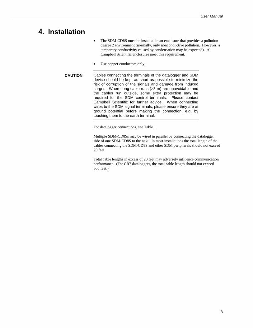
4. Installation • The SDM-CD8S must be installed in an enclosure that provides a pollution
degree 2 environment (normally, only nonconductive pollution. However, a temporary conductivity caused by condensation may be expected). All Campbell Scientific enclosures meet this requirement.
• Use copper conductors only.
Cables connecting the terminals of the datalogger and SDM device should be kept as short as possible to minimize the risk of corruption of the signals and damage from induced surges. Where long cable runs (>3 m) are unavoidable and the cables run outside, some extra protection may be required for the SDM control terminals. Please contact Campbell Scientific for further advice. When connecting wires to the SDM signal terminals, please ensure they are at ground potential before making the connection, e.g. by touching them to the earth terminal.
For datalogger connections, see Table 1.
Multiple SDM-CD8Ss may be wired in parallel by connecting the datalogger side of one SDM-CD8S to the next. In most installations the total length of the cables connecting the SDM-CD8S and other SDM peripherals should not exceed 20 feet.
Total cable lengths in excess of 20 feet may adversely influence communication performance. (For CR7 dataloggers, the total cable length should not exceed 600 feet.)
CAUTION
SDM-CD8S 8 Channel Solid State DC Control Module
4
4.1 Wiring
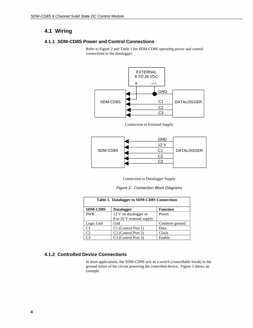
4.1.1 SDM-CD8S Power and Control Connections Refer to Figure 2 and Table 1 for SDM-CD8S operating power and control connections to the datalogger.
EXTERNAL8 TO 26 VDC
+ —
SDM-CD8S DATALOGGER
GND
C1C2C3
Connection to External Supply
SDM-CD8S DATALOGGER
GND12 VC1C2C3
Connection to Datalogger Supply
Figure 2. Connection Block Diagrams
Table 1. Datalogger to SDM-CD8S Connections
SDM-CD8S Datalogger Function PWR 12 V on datalogger or
8 to 26 V external supplyPower
Logic Gnd Gnd Common ground C1 C1 (Control Port 1) DataC2 C2 (Control Port 2) Clock C3 C3 (Control Port 3) Enable
4.1.2 Controlled Device Connections In most applications, the SDM-CD8S acts as a switch (controllable break) in the ground return of the circuit powering the controlled device. Figure 3 shows an example.

User Manual
5
DC Power
Supply
+ GND
SDM_CD8S
PWR +
G _
Load Power
Out Device
Figure 3. Typical Wiring Application
5. Address Selection Switch Each SDM-CD8S can have 1 of 16 addresses. Shipped from the factory, the address is set at 00. Table 2 shows switch position and the corresponding address.
Table 2. Switch Position and Addresses
Switch Setting
Base 10 Address CRBasic Dataloggers
Base 4 Address Edlog Dataloggers
0 0 00 1 1 01 2 2 02 3 3 03 4 4 10 5 5 11 6 6 12 7 7 13 8 8 20 9 9 21 A 10 22 B 11 23 C 12 30 D 13 31 E 14 32 F 15 33
SDM-CD8S 8 Channel Solid State DC Control Module
6
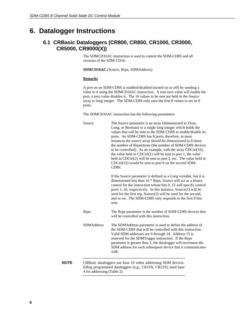
6. Datalogger Instructions 6.1 CRBasic Dataloggers (CR800, CR850, CR1000, CR3000,
CR5000, CR9000(X)) The SDMCD16AC instruction is used to control the SDM-CD8S and all versions of the SDM-CD16.
SDMCD16AC (Source, Reps, SDMAddress)
Remarks
A port on an SDM-CD8S is enabled/disabled (turned on or off) by sending a value to it using the SDMCD16AC instruction. A non-zero value will enable the port; a zero value disables it. The 16 values to be sent are held in the Source array or long integer. The SDM-CD8S only uses the first 8 values to set its 8 ports.
The SDMCD16AC instruction has the following parameters:
Source The Source parameter is an array (dimensioned as Float, Long, or Boolean) or a single long integer which holds the values that will be sent to the SDM-CD8S to enable/disable its ports. An SDM-CD8S has 8 ports; therefore, in most instances the source array should be dimensioned to 8 times the number of Repetitions (the number of SDM-CD8S devices to be controlled). As an example, with the array CDCtrl(16), the value held in CDCtrl(1) will be sent to port 1, the value held in CDCtrl(2) will be sent to port 2, etc. The value held in CDCtrl(32) would be sent to port 8 on the second SDM-CD8S. If the Source parameter is defined as a Long variable, but it is dimensioned less than 16 * Reps, Source will act as a binary control for the instruction whose bits 0..15 will specify control ports 1..16, respectively. In this instance, Source(1) will be used for the first rep, Source(2) will be used for the second, and so on. The SDM-CD8S only responds to the first 8 bits sent.
Reps The Reps parameter is the number of SDM-CD8S devices that will be controlled with this instruction.
SDMAddress The SDMAddress parameter is used to define the address of the SDM-CD8S that will be controlled with this instruction. Valid SDM addresses are 0 through 14. Address 15 is reserved for the SDMTrigger instruction. If the Reps parameter is greater than 1, the datalogger will increment the SDM address for each subsequent device that it communicates with.
CRBasic dataloggers use base 10 when addressing SDM devices. Edlog programmed dataloggers (e.g., CR10X, CR23X) used base 4 for addressing (Table 2).
NOTE

User Manual
7
CRBasic dataloggers also have the TimedControl instruction which allows a timed sequence of settings to be managed by the measurement task avoiding possible processing delays to cause delayed switching (pipeline mode only). See an example in Section 8.4.
6.2 Datalogger Instructions 104 (CR10/10X, CR23X, 21X, CR7) and 29 (older CR7s)
The CR10/10X, CR23X, CR7 and 21X use instruction 104 to control the SDM-CD8S. Instruction 29 is used by older CR7s. The Instruction descriptions are shown below.
Instruction 104 – SDM-CD8S used with CR10/10X, CR23X, CR7and 21X dataloggers
Parameter Type Description 1 2 Reps (No. of modules sequentially addressed) 2 2 Starting Address (base 4: 00..33) 3 4 Starting Input Location
Execution Time = 2ms per Rep for the CR10/10X and CR23X 3.5ms per Rep for the 21X and CR7
Instruction 29 – SDM-CD8S used with older CR7s
Parameter Type Description 1 2 Reps (No. of modules sequentially addressed) 2 2 Device (2 = SDM-CD8S) 3 2 Starting Address (base 4: 00..33) 4 2 Card (Excitation card No.) 5 4 Starting Input Location
Execution Time = 150ms to 190ms per Rep
The number of SDM-CD8Ss to be addressed is defined by the Reps (repetitions) parameter. Each Rep sequentially addresses (00, 01, 02,...32, 33) SDM-CD8Ss, starting with the address specified in parameter 2 (parameter 3 for Instruction 29).
For each repetition, the 8 ports of the addressed SDM-CD8S are set according to 16 sequential input locations starting at the input location specified in parameter 3 (parameter 5 for Instruction 29). Any non-zero value stored in an input location activates (sets HI 5V) the associated SDM-CD8S port. A value of zero (0) de-activates the port (sets LO 0V). For example, assuming two repetitions and a starting input location of 33, outputs 1 to 16 of the first SDM-CD8S are set according to input locations 33 to 48, and outputs 1 to 16 of the second SDM-CD8S are set according to input locations 49 to 64.
For older CR7s with Instruction 29, the Device (parameter 2) specifies what type of synchronously addressed peripheral is to be addressed. The Device code for an SDM-CD8S is 2.
For Instruction 29 only (older CR7s), the Card parameter (parameter 4) specifies which 725 Excitation Card is being used for the control port signals. The Reps parameter does not advance beyond the specified Card, requiring another Instruction 29 for each 725 Excitation Card used.

SDM-CD8S 8 Channel Solid State DC Control Module
8
7. Theory of Operation The SDM-CD8S is a synchronously addressed peripheral. C2 and C3, driven high by the datalogger, initiate a cycle. While holding C3 high, the datalogger drives C2 as a clock line and C1 as a serial data line. The datalogger shifts out a data bit on C1 (LSB first) on the falling edge of the C2 clock. The SDM-CD8S shifts in the C1 data bit on the rising edge of the C2 clock.
The first 8 bits clocked out represent the SDM-CD8S address. If the address matches the SDM-CD8S's address, the SDM-CD8S is enabled. If enabled, the next 16 bits are shifted into the SDM-CD8S, each bit controlling one port, the first of which controls OUT 1. (Only the first 8 bits are used by the SDM-CD8S.)
When the 16 control bits are clocked in, C2 is held high while C3 is pulsed low then high to latch the control bits. The datalogger then lowers both C3 and C2 to complete the cycle.
8. Program Examples 8.1 Control Temperature and Fans – CR1000
In this example, the SDM-CD8S is used to control the temperature between 23° and 28°C in 2 greenhouses. In each greenhouse the SDM-CD8S controls a heating unit, a refrigerating unit, and an air-mixing fan according to the following conditions.
Heating unit: Activate when temperature < 23.5°C. Deactivate when temperature > 25.5°C
Cooling unit: Activate when temperature > 27.5°C. Deactivate when temperature < 24.5°C
Mixing fan: Activate whenever the heating or cooling units are activated. Activate for 5 minutes out of every 15 minutes.
The program assumes the temperature measurements have been made, and the average temperature for each greenhouse is computed and residing in the appropriate variable

User Manual
9
Input Location assignments are as follows:
Variable Array Description
Temp(2) Avg temp, greenhouse 1 & 2
Heat(2) Heater control, greenhouse 1 & 2 SDM-CD8S Port 1 & 2
Cool(2) Cooler control, greenhouse 1 & 2 SDM-CD8S Port 3 & 4
Fan(2) Fan control, greenhouse 1 & 2 SDM-CD8S Port 5 & 6.
CD16_Output(16) EXAMPLE 1: the actual values used to control the SDM-CD8S: CD16_Output(I), I = 1 to 2 are for Heat, I = 3 to 4 are for Cooling, I= 5 to 6 are for Fans
CD16_Output as Long EXAMPLE 2: the actual value used to control SDMCD the CD16_Output bits set the SDM-CD8S ports. bits 0 & 1 are for Heat, 3 & 4 are for Cooling, 5 & 6 are for Fans

SDM-CD8S 8 Channel Solid State DC Control Module
10
The Example 1 program uses an array of values to set the SDM-CD8S control outputs:
'Program name: SDMCD8Example.CR1 'Date written: 3/25/2008 '\\\\\\\\\\\\\\\\\\\\\\\\\ DECLARATIONS ///////////////////////// Public Flag(8) As Boolean Public I Public Temp(2) Public Heat(2) Public Cool(2) Public Fan(2) ' Note CD16_Output(I), I = 1 & 2 are for Heat, I = 3 & 4 are for Cooling, I= 5 & 6 are for Fans Dim CD16_Output(16) '\\\\\\\\\\\\\\\\\\\\\\\\\\\ PROGRAM //////////////////////////// BeginProg Scan(5,Sec, 3, 0) For I = 1 To 2 If (Temp(I) < 23.5) Then Heat(I) = 1 ElseIf (Temp(I) >= 25.5) Then Heat(I) = 0 EndIf If (Temp(I) >= 27.5) Then Cool(I) = 1 ElseIf (Temp(I) < 24.5) Then Cool(I) = 0 EndIf If (Heat(I) <> 0) OR (Cool(I) <> 0) Then Fan(I) = 1 Else Fan(I) = 0 EndIf Next I If TimeIntoInterval(10,15,Min) Then Flag(2) = True If TimeIntoInterval(0,15,Min) Then Flag(2) = False If Flag(2) = True Then For I = 1 To 2 Fan(I) = 1 Next I EndIf For I = 1 To 2 CD16_Output(I) = Heat(I) CD16_Output(I+2) = Cool(I) CD16_Output(I+4) = Fan(I) Next I SDMCD16AC(CD16_Output(), 1, 0) NextScan EndProg
User Manual
11
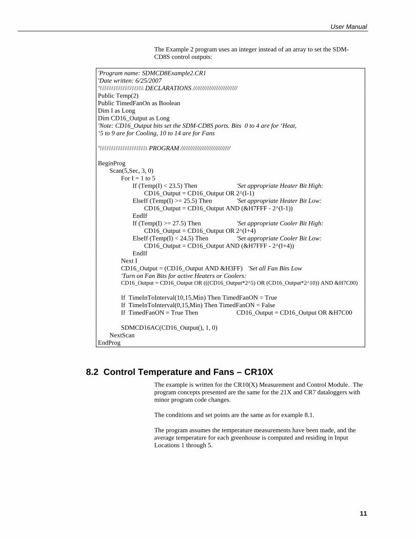
The Example 2 program uses an integer instead of an array to set the SDM-CD8S control outputs:
'Program name: SDMCD8Example2.CR1 'Date written: 6/25/2007 '\\\\\\\\\\\\\\\\\\\\\\\\\ DECLARATIONS ///////////////////////// Public Temp(2) Public TimedFanOn as Boolean Dim I as Long Dim CD16_Output as Long 'Note: CD16_Output bits set the SDM-CD8S ports. Bits 0 to 4 are for ‘Heat, ‘5 to 9 are for Cooling, 10 to 14 are for Fans '\\\\\\\\\\\\\\\\\\\\\\\\\\\ PROGRAM //////////////////////////// BeginProg Scan(5,Sec, 3, 0) For I = 1 to 5 If (Temp(I) < 23.5) Then 'Set appropriate Heater Bit High: CD16_Output = CD16_Output OR 2^(I-1) ElseIf (Temp(I) >= 25.5) Then 'Set appropriate Heater Bit Low: CD16_Output = CD16_Output AND (&H7FFF - 2^(I-1)) EndIf If (Temp(I) >= 27.5) Then 'Set appropriate Cooler Bit High: CD16_Output = CD16_Output OR 2^(I+4) ElseIf (Temp(I) < 24.5) Then 'Set appropriate Cooler Bit Low: CD16_Output = CD16_Output AND (&H7FFF - 2^(I+4)) EndIf Next I CD16_Output = (CD16_Output AND &H3FF) 'Set all Fan Bits Low 'Turn on Fan Bits for active Heaters or Coolers: CD16_Output = CD16_Output OR (((CD16_Output*2^5) OR (CD16_Output*2^10)) AND &H7C00) If TimeInToInterval(10,15,Min) Then TimedFanON = True If TimeInToInterval(0,15,Min) Then TimedFanON = False If TimedFanON = True Then CD16_Output = CD16_Output OR &H7C00 SDMCD16AC(CD16_Output(), 1, 0) NextScan EndProg
8.2 Control Temperature and Fans – CR10X The example is written for the CR10(X) Measurement and Control Module. The program concepts presented are the same for the 21X and CR7 dataloggers with minor program code changes.
The conditions and set points are the same as for example 8.1.
The program assumes the temperature measurements have been made, and the average temperature for each greenhouse is computed and residing in Input Locations 1 through 5.
SDM-CD8S 8 Channel Solid State DC Control Module
12
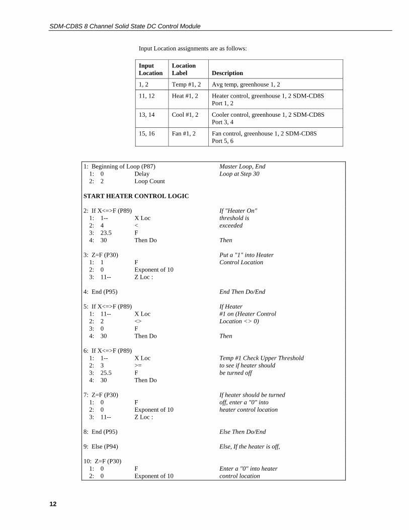
Input Location assignments are as follows:
Input Location
Location Label
Description
1, 2 Temp #1, 2 Avg temp, greenhouse 1, 2
11, 12 Heat #1, 2 Heater control, greenhouse 1, 2 SDM-CD8S Port 1, 2
13, 14 Cool #1, 2 Cooler control, greenhouse 1, 2 SDM-CD8S Port 3, 4
15, 16 Fan #1, 2 Fan control, greenhouse 1, 2 SDM-CD8S Port 5, 6
1: Beginning of Loop (P87) Master Loop, End 1: 0 Delay Loop at Step 30 2: 2 Loop Count START HEATER CONTROL LOGIC 2: If X<=>F (P89) If "Heater On" 1: 1-- X Loc threshold is 2: 4 < exceeded 3: 23.5 F 4: 30 Then Do Then 3: Z=F (P30) Put a "1" into Heater 1: 1 F Control Location 2: 0 Exponent of 10 3: 11-- Z Loc : 4: End (P95) End Then Do/End 5: If X<=>F (P89) If Heater 1: 11-- X Loc #1 on (Heater Control 2: 2 <> Location <> 0) 3: 0 F 4: 30 Then Do Then 6: If X<=>F (P89) 1: 1-- X Loc Temp #1 Check Upper Threshold 2: 3 >= to see if heater should 3: 25.5 F be turned off 4: 30 Then Do 7: Z=F (P30) If heater should be turned 1: 0 F off, enter a "0" into 2: 0 Exponent of 10 heater control location 3: 11-- Z Loc : 8: End (P95) Else Then Do/End 9: Else (P94) Else, If the heater is off, 10: Z=F (P30) 1: 0 F Enter a "0" into heater 2: 0 Exponent of 10 control location

User Manual
13
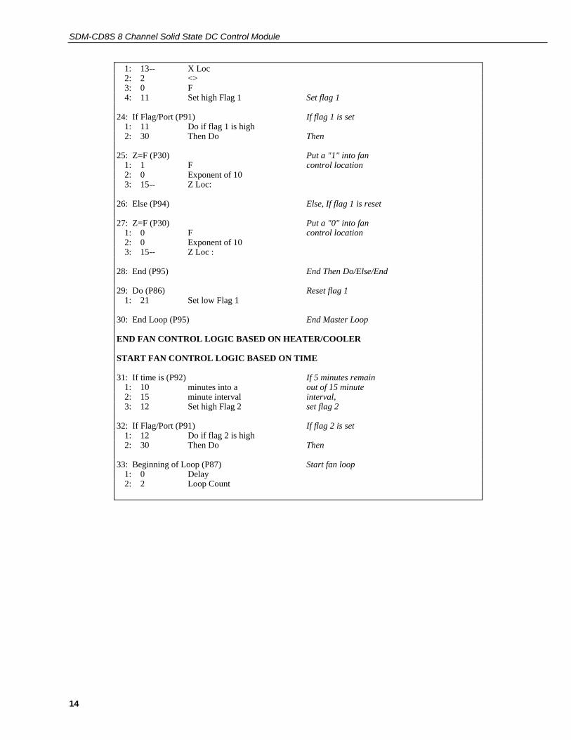
3: 11-- Z Loc : 11: End (P95) End Then Do/Else/End END HEATER CONTROL LOGIC START COOLER CONTROL LOGIC 12: If X<=>F (P89) If "Cooler" on 1: 1-- X Loc threshold is 2: 3 >= exceeded 3: 27.5 F 4: 30 Then Do Then 13: Z=F (P30) Put a "1" into cooler 1: 1 F Control Location 2: 0 Exponent of 10 3: 13-- Z Loc : 14: End (P95) End Then Do/End 15: If X<=>F (P89) If cooler is on 1: 13-- X Loc (Cooler control 2: 2 <> Location <>0) 3: 0 F 4: 30 Then Do Then 16: If X<=>F (P89) Check lower threshold to 1: 1-- X Loc see if cooler should be 2: 4 < turned off 3: 24.5 F 4: 30 Then Do 17: Z=F (P30) If cooler should be turned 1: 0 F off, put a "0" into cooler 2: 0 Exponent of 10 control location 3: 13-- Z Loc : 18: End (P95) End Then Do/End 19: Else (P94) Else if cooler is off 20: Z=F (P30) 1: 0 F Put a "0" into cooler 2: 0 Exponent of 10 control location 3: 13-- Z Loc : 21: End (P95) End Then Do/Else/End END COOLER CONTROL LOGIC START FAN CONTROL LOGIC BASED ON HEATER/COOLER 22: If X<=>F (P89) If heater is on 1: 11-- X Loc 2: 2 <> 3: 0 F 4: 11 Set high Flag 1 Set flag 1 23: If X<=>F (P89) If cooler is on
SDM-CD8S 8 Channel Solid State DC Control Module
14
1: 13-- X Loc 2: 2 <> 3: 0 F 4: 11 Set high Flag 1 Set flag 1 24: If Flag/Port (P91) If flag 1 is set 1: 11 Do if flag 1 is high 2: 30 Then Do Then 25: Z=F (P30) Put a "1" into fan 1: 1 F control location 2: 0 Exponent of 10 3: 15-- Z Loc: 26: Else (P94) Else, If flag 1 is reset 27: Z=F (P30) Put a "0" into fan 1: 0 F control location 2: 0 Exponent of 10 3: 15-- Z Loc : 28: End (P95) End Then Do/Else/End 29: Do (P86) Reset flag 1 1: 21 Set low Flag 1 30: End Loop (P95) End Master Loop END FAN CONTROL LOGIC BASED ON HEATER/COOLER START FAN CONTROL LOGIC BASED ON TIME 31: If time is (P92) If 5 minutes remain 1: 10 minutes into a out of 15 minute 2: 15 minute interval interval, 3: 12 Set high Flag 2 set flag 2 32: If Flag/Port (P91) If flag 2 is set 1: 12 Do if flag 2 is high 2: 30 Then Do Then 33: Beginning of Loop (P87) Start fan loop 1: 0 Delay 2: 2 Loop Count
User Manual
15
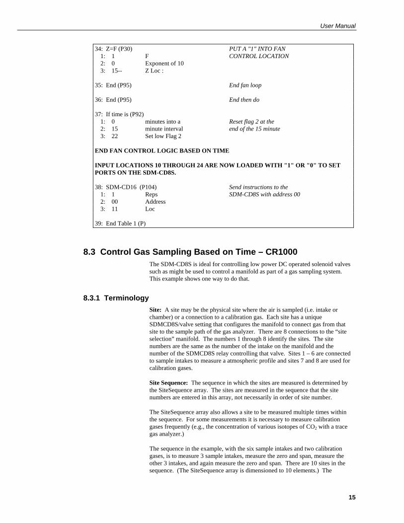
34: Z=F (P30) PUT A "1" INTO FAN 1: 1 F CONTROL LOCATION 2: 0 Exponent of 10 3: 15-- Z Loc : 35: End (P95) End fan loop 36: End (P95) End then do 37: If time is (P92) 1: 0 minutes into a Reset flag 2 at the 2: 15 minute interval end of the 15 minute 3: 22 Set low Flag 2 END FAN CONTROL LOGIC BASED ON TIME INPUT LOCATIONS 10 THROUGH 24 ARE NOW LOADED WITH "1" OR "0" TO SET PORTS ON THE SDM-CD8S. 38: SDM-CD16 (P104) Send instructions to the 1: 1 Reps SDM-CD8S with address 00 2: 00 Address 3: 11 Loc 39: End Table 1 (P)
8.3 Control Gas Sampling Based on Time – CR1000 The SDM-CD8S is ideal for controlling low power DC operated solenoid valves such as might be used to control a manifold as part of a gas sampling system. This example shows one way to do that.
8.3.1 Terminology Site: A site may be the physical site where the air is sampled (i.e. intake or chamber) or a connection to a calibration gas. Each site has a unique SDMCD8S/valve setting that configures the manifold to connect gas from that site to the sample path of the gas analyzer. There are 8 connections to the “site selection” manifold. The numbers 1 through 8 identify the sites. The site numbers are the same as the number of the intake on the manifold and the number of the SDMCD8S relay controlling that valve. Sites 1 – 6 are connected to sample intakes to measure a atmospheric profile and sites 7 and 8 are used for calibration gases.
Site Sequence: The sequence in which the sites are measured is determined by the SiteSequence array. The sites are measured in the sequence that the site numbers are entered in this array, not necessarily in order of site number.
The SiteSequence array also allows a site to be measured multiple times within the sequence. For some measurements it is necessary to measure calibration gases frequently (e.g., the concentration of various isotopes of CO2 with a trace gas analyzer.)
The sequence in the example, with the six sample intakes and two calibration gases, is to measure 3 sample intakes, measure the zero and span, measure the other 3 intakes, and again measure the zero and span. There are 10 sites in the sequence. (The SiteSequence array is dimensioned to 10 elements.) The

SDM-CD8S 8 Channel Solid State DC Control Module
16
sequence is 1, 2, 3, 7, 8, 4, 5, 6, 7, 8. Thirty seconds is spent on each site the sequence. Thus it takes 5 minutes to run through the sequence of 10 sites (10 sites x 30 seconds/site). This sequence is repeated again and again.
OmitCounts: When the manifold is switched to a new site, it is necessary to purge the line before the analyzer measurement represents the new site. The program includes a counter that is incremented by one each scan. The omit counts is number of measurements to exclude from an average for the site after switching to the site.
The program records averages for each time the manifold is set to a site. The average does not include values measured while the count is less that the omit count. The count is reset to 0 when the program switches to a new site. In this program there is a constant omitcounts that is used for all sites. If it was necessary to set the Omit Counts independently for each site, OmitCounts could be a variable array instead of a constant.
8.3.2 Data Tables There are two data tables, RawData and SiteAvg. RawData holds samples of every measurement. SiteAvg holds averages that are calculated for a site when the manifold is switched to the next site.
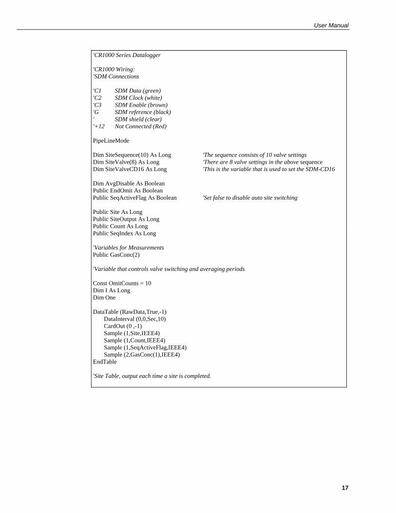
8.3.3 Initialization Section (between BeginProg and Scan) Manifold/SDMCD8S Settings: This section defines the bit pattern for each valve setting.
Site Sequence: Edit the SiteSequence array assignment for the sequence desired. For example, the 10 element SiteSequence array described in the Terminology section above can be loaded with the code:
'Load SiteSequence SiteSequence(1) = 1 SiteSequence(2) = 2 SiteSequence(3) = 3 SiteSequence(4) = 7 SiteSequence(5) = 8 SiteSequence(6) = 4 SiteSequence(7) = 5 SiteSequence(8) = 6 SiteSequence(9) = 7 SiteSequence(10) = 8
User Manual
17
'CR1000 Series Datalogger 'CR1000 Wiring: 'SDM Connections 'C1 SDM Data (green) 'C2 SDM Clock (white) 'C3 SDM Enable (brown) 'G SDM reference (black) ' SDM shield (clear) '+12 Not Connected (Red) PipeLineMode Dim SiteSequence(10) As Long 'The sequence consists of 10 valve settings Dim SiteValve(8) As Long 'There are 8 valve settings in the above sequence Dim SiteValveCD16 As Long 'This is the variable that is used to set the SDM-CD16 Dim AvgDisable As Boolean Public EndOmit As Boolean Public SeqActiveFlag As Boolean 'Set false to disable auto site switching Public Site As Long Public SiteOutput As Long Public Count As Long Public SeqIndex As Long 'Variables for Measurements Public GasConc(2) 'Variable that controls valve switching and averaging periods Const OmitCounts = 10 Dim I As Long Dim One DataTable (RawData,True,-1) DataInterval (0,0,Sec,10) CardOut (0 ,-1) Sample (1,Site,IEEE4) Sample (1,Count,IEEE4) Sample (1,SeqActiveFlag,IEEE4) Sample (2,GasConc(1),IEEE4) EndTable 'Site Table, output each time a site is completed.
SDM-CD8S 8 Channel Solid State DC Control Module
18
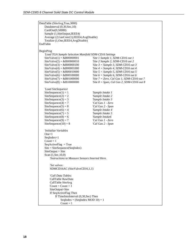
DataTable (SiteAvg,True,3000) DataInterval (0,30,Sec,10) CardOut(0,50000) Sample (1,SiteOutput,IEEE4) Average (2,GasConc(1),IEEE4,AvgDisable) Totalize (1,One,IEEE4,AvgDisable) EndTable BeginProg 'Load TGA Sample Selection Manifold SDM-CD16 Settings SiteValve(1) = &B00000001 'Site 1 Sample 1, SDM-CD16 out 1 SiteValve(2) = &B00000010 'Site 2 Sample 2, SDM-CD16 out 2 SiteValve(3) = &B00000100 'Site 3 = Sample 3, SDM-CD16 out 3 SiteValve(4) = &B00001000 'Site 4 = Sample 4, SDM-CD16 out 4 SiteValve(5) = &B00010000 'Site 5 = Sample 5, SDM-CD16 out 5 SiteValve(6) = &B00100000 'Site 6 = Sample 6, SDM-CD16 out 6 SiteValve(7) = &B01000000 'Site 7 = Zero, Cal Gas 1, SDM-CD16 out 7 SiteValve(8) = &B10000000 'Site 8 = Span, Cal Gas 2, SDM-CD16 out 8 'Load SiteSequence SiteSequence(1) = 1 'Sample Intake 1 SiteSequence(2) = 2 'Sample Intake 2 SiteSequence(3) = 3 'Sample Intake 3 SiteSequence(4) = 7 'Cal Gas 1 - Zero SiteSequence(5) = 8 'Cal Gas 2 - Span SiteSequence(6) = 4 'Sample Intake 4 SiteSequence(7) = 5 'Sample Intake 5 SiteSequence(8) = 6 'Sample Intake6 SiteSequence(9) = 7 'Cal Gas 1 - Zero SiteSequence(10) = 8 'Cal Gas 2 - Span 'Initialize Variables One=1 SeqIndex=1 Count = 1 SeqActiveFlag = True Site = SiteSequence(SeqIndex) SiteOutput = Site Scan (1,Sec,10,0) 'Instructions to Measure Sensors Inserted Here. 'Set valves: SDMCD16AC (SiteValveCD16,1,1) 'Call Data Tables: CallTable RawData CallTable SiteAvg Count = Count + 1 SiteOutput=Site If SeqActiveFlag Then If TimeIntoInterval (0,30,Sec) Then SeqIndex = (SeqIndex MOD 10) + 1 Count = 1

User Manual
19
EndIf Site = SiteSequence(SeqIndex) EndIf SiteValveCD16 = SiteValve(Site) EndOmit = Count > OmitCounts AvgDisable = NOT (EndOmit AND SeqActiveFlag) NextScan EndProg
8.4 Control Gas Sampling with Timing in Measurement Task – CR1000
8.4.1 The Purpose of this Example This example illustrates an instruction that can be used if:
1) There is a requirement for precisely timed switching in a known timing sequence.
2) The time required in the datalogger program for processing tasks is close to the scan interval.
If the processing occasionally takes longer than the scan interval, there could be skipped measurements (sequential mode) or the measurements could be made but the switching would take place later than expected (pipeline mode).
This program has the same timing and valve control as the example in Section 8.2, however, instead of the logic in the program determining when to switch the valves, it makes use of the TimedControl instruction to control when valves switch as part of the measurement task (pipeline mode only).
8.4.2 Pipeline vs Sequential The Pipeline mode is more efficient than the Sequential mode. In the Sequential mode, all processing is completed before advancing to the next instruction. The Pipeline mode separates the measurement and processing tasks. Not only does this separation of tasks allow the datalogger to complete both tasks in less time than the sequential mode, it allows the processing task to briefly fall behind the measurement task without skipping any measurements.
In the pipeline mode the results of the measurement task are stored in a buffer for the processing task. The processing task starts after the first measurement task is complete and can take place at the same time as the next measurement task. If the processing task has something that temporarily prevents it from finishing before the next measurement scan is complete, it can fall behind the measurement scan. Later when the processing is less intensive, the processing can run faster than the measurements and process the buffered measurement data and catch up to the measurement scan. Operations that may temporarily increase the processing are intensive calculations for final output processing, extra communications overhead, or initializing a new compact flash card.
In the example in Section 8.3, the logic that controls the SDM-CD8S is in the processing task. In the pipeline mode the measurements continue to occur at the proper time. If the processing falls behind the measurement the values used to set the SDM-CD8S will be updated only when the processing task gets to that point. This will be later than would be expected if the processing task were not falling behind.

SDM-CD8S 8 Channel Solid State DC Control Module
20
The TimedControl instruction allows the timing of when to switch SDMCD16 settings to be part of the measurement task rather than the processing task.
8.4.3 TimedControl Instruction TimedControl: This instruction allows a sequence of fixed values and durations (number of scans) to be controlled by the measurement task. It allows a series of SDM-CD16 settings to be defined so that the switching sequence occurs at the proper times even if processing is lagging behind the measurement task.
TimedControl(Size,Sync_interval, Interval_Units,Default_Value, Index_dest, Source_Array, ClockResetOpt)
Size: The number of values in the sequence.
Sync_interval: When the program is compiled and starts running or when the TimedControl is reset the program will wait until an even multiple of this interval to start the sequence. Enter 0 to start immediately. See Clock/Reset Option for more information on what happens prior to the start.
Interval_Units: The time units for the Sync_Interval.
Default_Value: The value to set the output to prior to starting the sequence.
Index_dest: A variable in which to store the index of the value that is currently being used in the source_array. This instruction will load 0 for the index if the instruction is waiting for the Sync_interval to start.
Source_Array: A two dimension array that contains the values to use and the duration (in number of scans) for which that value is to remain in use. For Example, arrayname(x,2) where the array must be dimensioned to have at least as many variables in the x dimension as the Size parameter requires. For any variable pair i, arrayname(i,1) = the value to set, and arrayname(i,2) = the duration in number of scans to use that value before moving to the next value in the array.
ClockResetOpt: When the TimedControl instruction occurs before BeginProg this option is used to set how the instruction behaves when the dataloggers clock is changed:
1. If the datalogger clock is changed, the instruction behaves as if it were just started after compile and the input to the SDMCD16 goes to the default.
2. The sequence continues running as if nothing happened until the next occurrence of the sync interval (synced to the current clock) and then restarts.
3. Ignore the change in the clock, keep the current count and index proceeding as if nothing happened.
User Manual
21
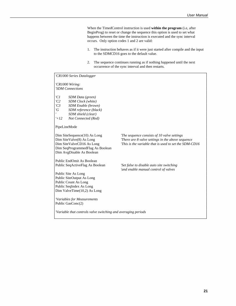
When the TimedControl instruction is used within the program (i.e, after BeginProg) to reset or change the sequence this option is used to set what happens between the time the instruction is executed and the sync interval occurs. Only option codes 1 and 2 are valid:
1. The instruction behaves as if it were just started after compile and the input to the SDMCD16 goes to the default value.
2. The sequence continues running as if nothing happened until the next occurrence of the sync interval and then restarts.
'CR1000 Series Datalogger 'CR1000 Wiring: 'SDM Connections 'C1 SDM Data (green) 'C2 SDM Clock (white) 'C3 SDM Enable (brown) 'G SDM reference (black) ' SDM shield (clear) '+12 Not Connected (Red) PipeLineMode Dim SiteSequence(10) As Long 'The sequence consists of 10 valve settings Dim SiteValve(8) As Long 'There are 8 valve settings in the above sequence Dim SiteValveCD16 As Long 'This is the variable that is used to set the SDM-CD16 Dim SeqProgrammedFlag As Boolean Dim AvgDisable As Boolean Public EndOmit As Boolean Public SeqActiveFlag As Boolean 'Set false to disable auto site switching 'and enable manual control of valves Public Site As Long Public SiteOutput As Long Public Count As Long Public SeqIndex As Long Dim ValveTime(10,2) As Long 'Variables for Measurements Public GasConc(2) 'Variable that controls valve switching and averaging periods

SDM-CD8S 8 Channel Solid State DC Control Module
22
Public OmitCounts(8) As Long Dim I As Long Dim One DataTable (RawData,True,-1) DataInterval (0,0,Sec,10) CardOut (0 ,-1) Sample (1,Site,IEEE4) Sample (1,Count,IEEE4) Sample (1,SeqActiveFlag,IEEE4) Sample (2,GasConc(1),IEEE4) EndTable 'Site Table, output each time a site is completed. DataTable (SiteAvg,True,3000) DataInterval (0,30,Sec,10) CardOut(0,50000) Sample (1,SiteOutput,IEEE4) Average (2,GasConc(1),IEEE4,AvgDisable) Totalize (1,One,IEEE4,AvgDisable) EndTable 'A TimedControl instruction must be placed before the BeginProg to set up for the instruction TimedControl(10,2,Min,1,SeqIndex,ValveTime,2) BeginProg 'Load TGA Sample Selection Manifold SDM-CD16 Settings SiteValve(1) = &B00000001 'Site 1 Sample 1, SDM-CD16 out 1 SiteValve(2) = &B00000010 'Site 2 Sample 2, SDM-CD16 out 2 SiteValve(3) = &B00000100 'Site 3 = Sample 3, SDM-CD16 out 3 SiteValve(4) = &B00001000 'Site 4 = Sample 4, SDM-CD16 out 4 SiteValve(5) = &B00010000 'Site 5 = Sample 5, SDM-CD16 out 5 SiteValve(6) = &B00100000 'Site 6 = Sample 6, SDM-CD16 out 6 SiteValve(7) = &B01000000 'Site 7 = Zero, Cal Gas 1, SDM-CD16 out 7 SiteValve(8) = &B10000000 'Site 8 = Span, Cal Gas 2, SDM-CD16 out 8 'Load SiteSequence SiteSequence(1) = 1 'Sample Intake 1 SiteSequence(2) = 2 'Sample Intake 2 SiteSequence(3) = 3 'Sample Intake 3 SiteSequence(4) = 7 'Cal Gas 1 - Zero SiteSequence(5) = 8 'Cal Gas 2 - Span SiteSequence(6) = 4 'Sample Intake 4 SiteSequence(7) = 5 'Sample Intake 5 SiteSequence(8) = 6 'Sample Intake6 SiteSequence(9) = 7 'Cal Gas 1 - Zero SiteSequence(10) = 8 'Cal Gas 2 - Span

User Manual
23
'Load Sequence Timing Array For I = 1 To 10 'Load the Valve and Timing Array with the valve Settings: ValveTime(I,1) = SiteValve(SiteSequence(I)) 'Load the Valve and Timing Array with the number of scans at each setting: ValveTime(I,2) = 30 Next I 'Initialize Variables One=1 SeqIndex=1 Count = 1 SeqActiveFlag = True Site = SiteSequence(SeqIndex) SiteOutput = Site Scan (1,Sec,10,0) 'Instructions to Measure Sensors Inserted Here. 'Set valves: SDMCD16AC (ValveTime(1,1),1,1) 'Call Data Tables: CallTable RawData CallTable SiteAvg Count = Count + 1 SiteOutput=Site If SiteAvg.Output(1,1) Then Count = 1 'Reset Count when the 'Site average is output If SeqActiveFlag Then Site = SiteSequence(SeqIndex) 'Show the site number set by 'the Timed Control If SeqProgrammedFlag = False Then 'Reset the first valve to 'the automatic value ValveTime(1,1) = SiteValve(1) ValveTime(1,2) = 30 TimedControl(10,2,Min,1,SeqIndex,ValveTime,2) TimedControl(10,2,Min,1,SeqIndex,ValveTime,2) SeqProgrammedFlag = True EndIf Else 'Set the first valve setting to that for the current Site 'The Site number may be changed by user to switch sites. ValveTime(1,1) = SiteValve(Site) ValveTime(1,2) = 0 If SeqProgrammedFlag = True Then 'Set the timed control to only 'use The first value TimedControl(1,0,Min,SiteValve(Site),SeqIndex,ValveTime,1) SeqProgrammedFlag = False EndIf EndIf SiteValveCD16 = SiteValve(Site) EndOmit = Count > OmitCounts(Site) AvgDisable = NOT (EndOmit AND SeqActiveFlag) NextScan EndProg

CAMPBELL SCIENTIFIC COMPANIES
Campbell Scientific, Inc. (CSI) 815 West 1800 North Logan, Utah 84321 UNITED STATES
www.campbellsci.com • [email protected]
Campbell Scientific Africa Pty. Ltd. (CSAf) PO Box 2450
Somerset West 7129 SOUTH AFRICA
www.csafrica.co.za • [email protected]
Campbell Scientific Australia Pty. Ltd. (CSA) PO Box 8108
Garbutt Post Shop QLD 4814 AUSTRALIA
www.campbellsci.com.au • [email protected]
Campbell Scientific do Brazil Ltda. (CSB) Rua Luisa Crapsi Orsi, 15 Butantã
CEP: 005543-000 São Paulo SP BRAZIL www.campbellsci.com.br • [email protected]
Campbell Scientific Canada Corp. (CSC)
11564 - 149th Street NW Edmonton, Alberta T5M 1W7
CANADA www.campbellsci.ca • [email protected]
Campbell Scientific Centro Caribe S.A. (CSCC)
300N Cementerio, Edificio Breller Santo Domingo, Heredia 40305
COSTA RICA www.campbellsci.cc • [email protected]
Campbell Scientific Ltd. (CSL)
Campbell Park 80 Hathern Road
Shepshed, Loughborough LE12 9GX UNITED KINGDOM
www.campbellsci.co.uk • [email protected]
Campbell Scientific Ltd. (France) 3 Avenue de la Division Leclerc
92160 ANTONY FRANCE
www.campbellsci.fr • [email protected]
Campbell Scientific Spain, S. L. Avda. Pompeu Fabra 7-9
Local 1 - 08024 BARCELONA SPAIN
www.campbellsci.es • [email protected]
Campbell Scientific Ltd. (Germany) Fahrenheitstrasse13, D-28359 Bremen
GERMANY www.campbellsci.de • [email protected]
Please visit www.campbellsci.com to obtain contact information for your local US or International representative.