SDL, A Graphical Language Useful to Describe Social Simulation Models
20
SDL, a graphical language useful to describe social simulation models Pau Fonseca i Casas 1 1 Universitat Politècnica de Catalunya. Campus Nord. Jordi Girona 1-3 08034, Catalunya, España {[email protected]} Abstract. Simulation, and specifically social simulation, is a discipline that usually involves professionals with different formation. This implies that the modeling languages, tools and infrastructures used to model can be diverse. This paper has the main objective of show a graphical language, widely used in the engineering field, which allows a complete graphical and no ambiguous description of a simulation model. The language, named SDL (Specification and Description Language) is defined by the ITU-T (on the Z.100 recommendation). Since SDL is a standard different tools understand the language, allowing a simulation or an automatic code generation from the SDL description of the model. This paper has two main sections, first we describe the rudiments of the language, and second we shown an example of a multi- agent system description using SDL language. Keywords: Social simulation, MAS, SDL language, formalization. 1. Introduction The construction of a simulation model sometimes lacks in the formalization process, needed to understand the structure and the behavior of the model before any specific implementation. Different advantages exist related with the conceptual model use. Among them we remark five. (i) Textual specification is less precise than formalization. (ii) Formalization represents in a detailed way, the existing dynamic relations between the different key elements of the process. (iii) This knowledge of the model behavior helps in the implementation process, keeping the independency between the model and the tool selected to carry out the implementation. (iv) Formalism improves the communication channels between the personnel related with the construction of the simulation model. (v) Some authors, like Brade [1] suggest that the a formalization of a simulation model can be considered a product by itself, empathizing the idea that the formalization process helps in the complete understanding of the relations derived from the system observation. This problem, which has been discussed largely in the simulation area, now is discussed in the more specific area of the social simulation [2], with some semi formal approximations like the Agent Modelling Language of Trencansky and Cervenka [3] among others.
Transcript of SDL, A Graphical Language Useful to Describe Social Simulation Models

SDL, a graphical language useful to describe social
simulation models
Pau Fonseca i Casas1
1 Universitat Politècnica de Catalunya. Campus Nord. Jordi Girona 1-3
08034, Catalunya, España
Abstract. Simulation, and specifically social simulation, is a discipline that
usually involves professionals with different formation. This implies that the
modeling languages, tools and infrastructures used to model can be diverse.
This paper has the main objective of show a graphical language, widely used in
the engineering field, which allows a complete graphical and no ambiguous
description of a simulation model. The language, named SDL (Specification
and Description Language) is defined by the ITU-T (on the Z.100
recommendation). Since SDL is a standard different tools understand the
language, allowing a simulation or an automatic code generation from the SDL
description of the model. This paper has two main sections, first we describe
the rudiments of the language, and second we shown an example of a multi-
agent system description using SDL language.
Keywords: Social simulation, MAS, SDL language, formalization.
1. Introduction
The construction of a simulation model sometimes lacks in the formalization process,
needed to understand the structure and the behavior of the model before any specific
implementation. Different advantages exist related with the conceptual model use.
Among them we remark five. (i) Textual specification is less precise than
formalization. (ii) Formalization represents in a detailed way, the existing dynamic
relations between the different key elements of the process. (iii) This knowledge of
the model behavior helps in the implementation process, keeping the independency
between the model and the tool selected to carry out the implementation. (iv)
Formalism improves the communication channels between the personnel related with
the construction of the simulation model. (v) Some authors, like Brade [1] suggest
that the a formalization of a simulation model can be considered a product by itself,
empathizing the idea that the formalization process helps in the complete
understanding of the relations derived from the system observation.
This problem, which has been discussed largely in the simulation area, now is
discussed in the more specific area of the social simulation [2], with some semi
formal approximations like the Agent Modelling Language of Trencansky and
Cervenka [3] among others.

Because the purpose of a model is not only to predict the behavior of the system,
but also explain and understand its behavior or perceive new questions [4], the
formalization process can be an inestimable tool in order to obtain these benefits.
This paper proposes the use of a well known language, SDL, to represent a
simulation model, and specifically a social simulation model.
In the simulation area other formalisms exists, like Petri Nets [5], [6], [7] or DEVS
[8], [9] among others. More specifically in the area of multi-agent simulation some
efforts have been done to develop a formalism [10],[11], [3], [12].
The proposed language, SDL [13],[14],[15],[16], (acronym of Specification and
Description Language), is a well known standard widely use in the engineering and
telecommunications area. Since SDL allows the definition of distributed systems, the
model defined with SDL is ready to be executed over different computers without the
need of modify its structure. Of course the platform selected to perform the simulation
must allow this feature.
Fig. 1. The formalization of a simulation model can be considered a product by itself, since
allows a better understanding of the system behavior [1].
Why SDL? SDL is a powerful and modern language used in different areas, not
only in the simulation area. It was been standardized by the International
Telecommunications Union (ITU) on the Z.100 recommendation, and can be used
easily in combination with other standard languages, like UML.
Anyway is not our intention to say what is the best language or formalism to be
used to represent social models, we think that a language is good if it is useful to
simplify, document and understand better the modeling process. As Vangheluwe [17]
say, the specification language must be comprehensible and unambiguous, helping
personnel without technical formation it’s quickly understanding. Nevertheless, the
language must be powerful to allow the model complexity representation.

With this objective we present a methodology easy to use but completely formal,
which allows acquiring a deeper understanding of the model behavior and helps in its
implementation process, keeping the independency between the model and the tool
selected to implement the model.
In the next section we describe the more important elements of the SDL language.
2. SDL language
SDL is an object oriented formal language defined by the International
Telecommunications Union–Telecommunications Standardization Sector (ITU–T)
(the Comité Consultatif International Telegraphique et Telephonique [CCITT]) on the
Z. 100 recommendation. The language was designed for the specification of event
oriented, real time and interactive complex systems. These systems can involucres
different concurrent activities that use signals to perform the communication [14],
[16], [15]. SDL is based in the definition of four levels (one kind of diagram for each
level) to describe the structure and the behavior of the models: system, blocks,
processes and procedures. In SDL blocks and processes are named agents, and the
outermost block, the system block is an agent itself. In the next figure this hierarchy is
shown.
Fig. 2. An structural vision of an SDL model. 4 main different levels exist (source:
http://www.iec.org/online/tutorials/sdl/topic04.html)
The different concepts that the SDL language covers are:
1. The structure: through the system, the blocks and the processes and its
related hierarchy.
2. The communication: through the signals, the communication paths (the
channels), and the parameters that can be carried by the signals.
3. The behavior: defined with the different process.
4. The data: based in ADT (Abstract Data Types).
5. The inheritance: useful to describe relations between objects and its
specializations.

A textual SDL exists, this paper is focused in the graphical representation of the
language (named SDL/GR), however all the discussion is valid for its textual
representation too (named SDL/PR), since both are equivalents [15].
process P;
start;
nextstate idle;
state idle;
input s;
output t;
nextstate idle;
endstate idle;
endprocess P;
Fig. 3. The same model represented by GS-SDL and PR-SDL.
To know more about the SDL language the recommendation Z.100 [15] can be
consulted, or the web site www.sdl-forum.org. The next sub sections have a brief
description of each one of the different levels of SDL.
2.1. System diagram
This is the outermost agent. As we said is unique and represented in the first level of
model decomposition. Here you can find the basic elements that constitute the model
and the communication channels between them and the exterior. The next figure
shows an example of a system diagram containing three blocks [18].
Fig. 4. System diagram. In this example the system is formed by three blocks, named block1,
block2 and block3. The behavior of these blocks is not represented here; we must wait to see
this behavior in the next diagrams. As you can see DLCaSU channel (and DLCbSU channel for
the block2) are receiving and sending signals from and to the exterior of the model (the signals
are dlc2su and su2dlc for both blocks).
Each rectangle represents an agent (in this case a block). Usually these blocks
represent elements of the system that can be decomposed in other SDL elements
(blocks or process). The lines between the blocs are communication channels; in this
idle
t
s
idle
idle
1(1)process P

case (as we can see in the next sub section) the channels are bidirectional and
delaying channels. Each one of the channels joins the objects through the ports, and
may have a name (in this case all the channels have a name). The name of the
channels and the ports are important to define the final destination of the different
signals, for instance if the path that can follow a specific signal is not unique.
For each one of the different blocks (or process) represented in this first diagram a
new diagram (block or process diagram) is build, defining the division of the model in
smaller components (the model structure).
2.1. SDL communication channels
The SDL communication channels that can be found in the SDL diagram are delaying
and non delaying channels.
The non delaying channels allow the automatic transmission of the information
(signals). There is no delay in the signal transmission. The representation of these
channels is shown in Fig. 5 and Fig. 6.
Fig. 5. SDL representation for non delaying channels. The name of the channel is C1 and C2,
the signals that can carry the channels are S1, S2, S3 and S4.
Fig. 6. SDL representation of delaying channels.
In a simulation model the time related to each signal belongs to the model
behavior, hence this time must be represented in the specification of the model. A
problem exists regarding this with SDL, since there is no way to define the duration
of a delay in a delaying channel [15]. In the next section, reviewing the adaptation of
SDL for a social simulation model we analyze this problem and show the proposed
solution.
2.2. SDL block diagrams
For each one of the different blocks defined in the system diagram is needed to define
a block diagram. In the next figure is shown the definition of two of the blocks of the
Fig. 6.
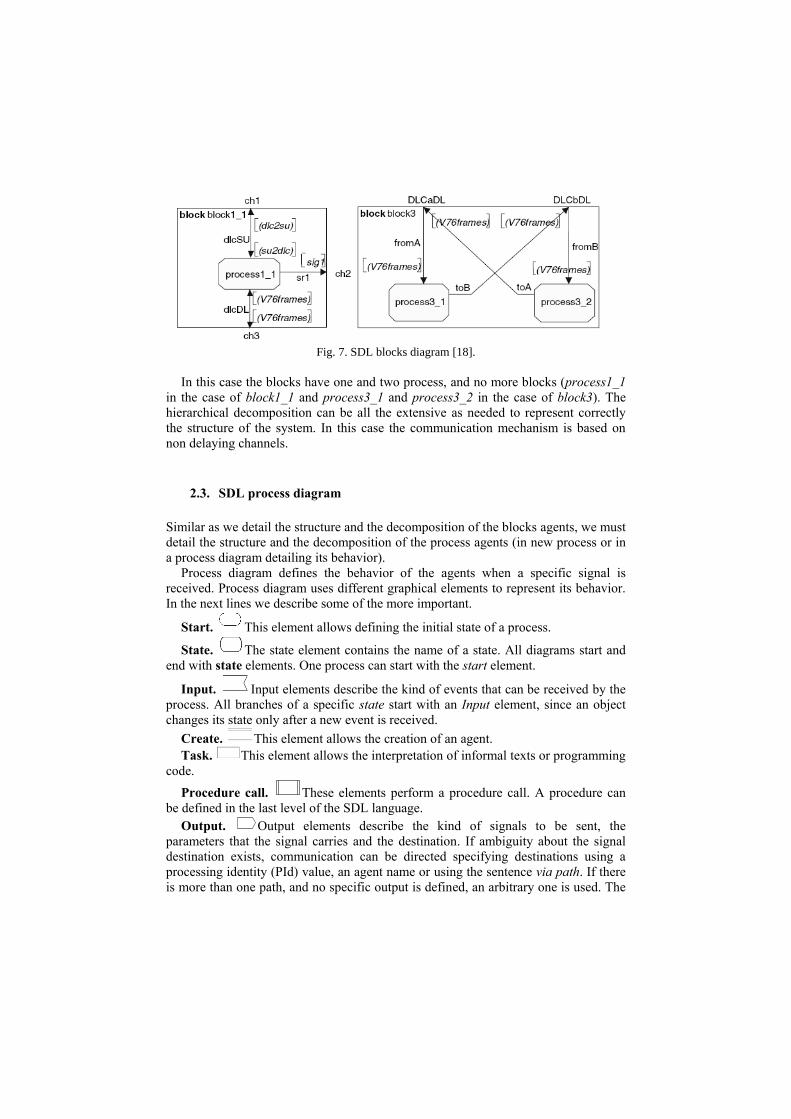
Fig. 7. SDL blocks diagram [18].
In this case the blocks have one and two process, and no more blocks (process1_1
in the case of block1_1 and process3_1 and process3_2 in the case of block3). The
hierarchical decomposition can be all the extensive as needed to represent correctly
the structure of the system. In this case the communication mechanism is based on
non delaying channels.
2.3. SDL process diagram
Similar as we detail the structure and the decomposition of the blocks agents, we must
detail the structure and the decomposition of the process agents (in new process or in
a process diagram detailing its behavior).
Process diagram defines the behavior of the agents when a specific signal is
received. Process diagram uses different graphical elements to represent its behavior.
In the next lines we describe some of the more important.
Start. This element allows defining the initial state of a process.
State. The state element contains the name of a state. All diagrams start and
end with state elements. One process can start with the start element.
Input. Input elements describe the kind of events that can be received by the
process. All branches of a specific state start with an Input element, since an object
changes its state only after a new event is received.
Create. This element allows the creation of an agent.
Task. This element allows the interpretation of informal texts or programming
code.
Procedure call. These elements perform a procedure call. A procedure can
be defined in the last level of the SDL language.
Output. Output elements describe the kind of signals to be sent, the
parameters that the signal carries and the destination. If ambiguity about the signal
destination exists, communication can be directed specifying destinations using a
processing identity (PId) value, an agent name or using the sentence via path. If there
is more than one path, and no specific output is defined, an arbitrary one is used. The

destination value can be stored in a variable for later use [14]. Four PId expressions
can be used:
self an agent’s own identity;
parent the agent that created the agent (Null for initial agents).
offspring the most recent agent created by the agent.
sender the agent that sent the last signal input (null before any signal
received).
Decision. These elements describe bifurcations. Their behavior depends on how
the related question is answered.
In the next figure a process diagram is shown.
Fig. 8. SDL process diagram for the ready state of the process process1_1 [18].
2.4. SDL procedures diagram
The last level of the SDL language allows the description of the procedures that can
be used in the process diagrams through the procedure calls . These diagrams are
very similar to the process diagrams, with the exception that they don’t need the states
definition. The next figure shows an example of a procedure.
Fig. 9. Description of the procedure sendFrame [18].

3. Using SDL for the representation of social models
To use SDL to represent social models first is needed to understand the particularities
that these models can have.
A system is a set of entities, (machines, people, etc), interacting with a common
objective [19]. This objective can be explicit or implicit; hence, all system offers
resistance to the change. In practical, the definition of what is and what is not a
system depends on the object of study. To simplify the study of the system through
the model the concept of model state is defined from a set of model variables. This set
of variables allows the description of how the system is in a specific time instant.
Analyzing the evolution of the variables that define the state of the model we can
establish a first classification of the simulation models, continuous simulation models
and discrete simulation models.
Models can also be classified depending on the evolution of the rules that defines
its behavior. The models that modify its behavior during the execution of the
simulation are evolutionary models; the models that never modify its rules are the
interactive models [20]. In interactive models the results are obtained from the
interaction of the different model elements1.
Table 1. Systems classification depending on time and evolving rules usage [20].
Static systems Dynamic systems
Interactive Static interactions. The
only changes are in the
composition. For instance,
systems that are not modified
over time. Through Monte
Carlo simulations, an
approximate value can be
obtained.2
System interaction.
Changes in the interactions
between the different model
components. For instance,
an industrial plant.
Evolutionary Evolutionary selection.
Random acquisition of
variations that change the
composition of types.
Evolutionary system
feedback that influences the
supply of variation and the
speed of evolution. Changes
in type depend on the history
of the system. For instance,
the evolution of a society or
wildfire with the interaction
of an extinction model.
1 “The interest of the interactionist perspective is usually focusing on the emergence of
aggregated patterns of behavior and its effect in larger systems.” [20]. 2 One example of an interactive static system is pi-calculus using Monte Carlo simulations. In
this example, there is no time but the composition is modified during the simulation because
the procedure produces an increasing number of points (with more points, the value is closer
to the value of pi).

Models can also be classified depending on time variable. If the model is static (the
time variable is not modified, or is not taken in consideration) or is dynamic (time is
one of the variables that must be analyzed). Table 1 shows a classification of the
models depending on the static/dynamic and interactive/evolutionist criteria. The
classification of a system as interactive or evolutionary depends on the temporal
scope of the problem being studied. For instance, if the lifetime of the simulation
model is short in relation with the feedback derived from the entities behavior
modifications (this feedback has no effects on the model execution), then an
interactive model should suffice.
SDL has been used for years to represent interactive dynamic systems. In order to
use it to represent social phenomenon SDL must be capable to represent an
evolutionary system.
Evolutionary norms can be represented in different ways, but usually multi agent
systems (MAS) allow the definition of models capable to implement some kind of
evolution. Focusing the attention in the representation and the implementation of
dynamic evolutionary models, different algorithms can be used, for instance [21]
discuss the use of genetic algorithms, genetic programming and systems of
classification to be used in social systems. The key in the evolutionary models is the
capacity to learn. Different learning models exists [22], the evolutionary learning,
learning along the live and cultural learning. Usually these learning methods can be
implemented in two levels, in the individual level these methods can be represented
with an approximation founded in the behavior based learning. In the population level
can be represented using genetic algorithms [23].
Intelligent agents can implement procedures to allow knowledge acquisition,
allowing a modification of its behavior. Since these procedures can belong to each
agent, the specific learning methods of each agent are independent of the state of the
whole agent colony. Also procedures managing a genetic pool can be defined, sharing
information between all the agents of the colony. MAS are good candidates to
represent an evolutionary and dynamic simulation model; hence the SDL language
must be capable to represent intelligent agents. In a theoretical level, an intelligent
agent can be represented like the next figure shows.
Fig. 10. Schematic representation of an intelligent agent.

An intelligent agent receives information using its sensors. According with the
received information executes actions with the effectors or actuators. An intelligent
agent adds evolutionary capacity to the whole model, since, as we said before, can
implement algorithms to allow a learning capacity causing the modification of its
behavior. Different intelligent agents exist depending on how the information is
processed. Cortés et. alt. [24] proposes the next classification.
1. Simple reflexive agents: this kind of agents does not have states. Its
actions are answers to the perceptions received. The connection between
perceptions and actions are based in condition-action rules.
2. Model based reflexive agents: these agents have states. This allows the
use of more information to give an answer. They are based in the idea that
the sensors do not give all the information needed. The agent stores
important information to complete the sensors information in order to
perform the correct action.
3. Goal based agents: the agents have goals to be achieved. These goals
allow the discrimination of the actions to be done.
4. Utility based agents: goals not guarantee that the agent conduct is useful.
For that, the utility function is defined. This function allows choosing the
actions that maximize this function.
The next figure shows a schema representing the simple reflexive agent.
Fig. 11. Schematic representation of a simple reflexive agent.

The behavior of this agent can be summarized in the next steps:
1. The agent is waiting, until some information of the environment is received.
2. The agent process the environment information received and uses the
condition/action rules to determine what to do.
3. The agent can initiate different actions to answer to the stimulus it receives.
When all the actions have been done, the agent returns to the waiting state.
With these considerations in the next section, we propose a specification of a
simple reflexive agent using the SDL language.
The representation of the other kind of agents can also be done using this language.
Only to mention that we can also represent the agent goals or its utility functions,
since SDL language allows the definition of procedures (in the last level of the
language, as we can see in the section 2.4).
4. SDL simple reflexive intelligent agent representation
In a simulation model, the signals represent the events that rule the model evolution.
Since the simulation engine is the structure that manages the delays of the model
usually all the signals are send to this structure who decides what the next event to be
processed is and what must be the element that process it. Since the delays are related
to the signals the first problem is how we can represent this with SDL language.
Delaying channels cannot be used, since the delay cannot be specified [15]3. For that
the channels used will be always non-delaying channels as we see in the section 2.1.
To solve the problem and allow the complete definition of the time related to the
signals delays, all the signals must carry a parameter named event. This parameter (a
structure represented in the Fig. 12) at least has three attributes (creation time,
execution time and priority). Thanks to this parameter we can specify completely all
the needed elements of the simulation model4.
3 Also the delays can be defined with timers, but this solution complicates the specification of
the model. 4 To implement this approximation different alternative exists, for instance the implementation
of an event scheduling simulation engine.

Fig. 12. SDL SIM package containing the structure event. Only CreationTime, ExecutionTime
and Priority are always needed in order to define a simulation model. However other
parameters can be contained in this structure as is shown in this figure.
With these considerations the formalization of a simple reflexive intelligent agent
is shown in the next figures. The first level of the SDL diagram defines the blocks or
process that composes the system. In this example only one typology of agents (in
MAS sense) are used, enclosed in the Population block.
Fig. 13. System diagram of MAS model.
As is represented in the diagram, agents composing Population block receive only
two kinds of events EnviromentInformation or Begin. EnviromentInformation signal
have two parameters event (containing the information previously described) and info,
a structure containing the information that can be perceived by the agents. In the next
figure is shown an example of INFO package containing the structure info with the
definition of the different environmental elements that can be perceived by the agent.

Fig. 14. Package “info”; this package is an example of environmental information that can be
perceived by the agent (and representing what the agent can modify).
The great advantage of defining a package containing the info structure is again the
modularity, since allows the definition of what can be perceiver and what can be
modified in a single structure. This simplifies the validation and verification process.
As we can see, no behavior is defined yet in this first level of the model structure.
To define the behavior of the model (hence the behavior of the agents), is needed to
define the next levels of the SDL language.
Detailing the characterization of Population block, we define its hierarchical
segmentation in the next diagram. Its composition is basically defined by a single
process named PSimpleRAgent. The numbers (1,10) define the minimum number of
agents (at the beginning of the model execution) and the maximum number of agents
allowed in the model (usually created by a create operation).
Fig. 15. The processes contained in the Population block are PSimpleRAgent process
representing the intelligent agents.
At this point the structure of the Population block is fully defined, and we can start
the definition of the model behavior through the PSimpleRAgent process diagram.
A simple reflexive agent reacts to the stimulus using its condition/action rules.
However some ambiguities exists in the textual description we done in the previous
section. As an example we don’t know what happens if an agent that is executing an
action receives a new stimulus from the environment (can the agent execute both

actions in parallel? Or the agent must wait to process the new stimulus until finish its
action?. Or the agent must ignore the new stimulus?).
The next figures (Fig. 16, Fig. 17 and Fig. 18) details the SDL process diagram for
a reflexive intelligent agent with the next assumptions about its behavior
(assumptions that are represented in the diagrams).
Fig. 16. Reflexive agent Inactive state process diagram. In Inactive state the agent
ignores all the signals except begin.
First the agent is Inactive, ignoring the entire external stimulus until begin signal is
received. When begin is received, the agent changes its state to Waiting or
ExecutingAction, depending on its memory. This memory stores the state of the agent
before become Inactive, (initialized Waiting by default in the Initialize procedure).
When EnviromentInformation signal is received the agent starts to process this
information, and changes the state to ExecutingAction. Once the information is
processed, depending on the time defined in the procedure ReactionTime (defined in
the last level of the SDL), the agent starts its actions (generating a new signal with the
time defined in the procedure ExecutionTime).
As we can see this agent can perform different actions in parallel, since admits the
reception of new EnviromentInformation signals when is in the state ExecutingAction
(no EnviromentInformation signal is discarded). If this behavior is correct for more
than one project we can reuse it and redefine only the last level of the SDL language

defining the ReactionTime and ExecutionTime procedure. This allows the creation of
simulation objects collections.
Fig. 17. Reflexive agent Waiting state process diagram. In the Waiting state, the
intelligent agent is not performing any action. Only a new EnvironmentInformation
event can modify its state (the agent is a simple reflexive agent, only reacts to the
environment stimulus, but do not make automatic actions). When a sensor obtains
new information, the agent goes to the ExecutingAction state. The attribute
E.ExecutionTime stores the time that the agent needs to process this information. Note
that the function ReactionTime depends on the agent behavior and is specified on the
fourth level of SDL language. An output event is produced and send to itself,
InformationProcessed, with two parameters, the event structure E, and the info
structure I that defines the information received by the sensor.

Fig. 18. Reflexive agent ExecutingAction state process diagram. For each
EnviromentInformation signal received, the agent starts new actions, as we see in the previous
diagrams. When the agent receives the ActionExecuted signal the agent has finish the action.

5. The procedures
Two main procedures exists in this example however we only shown, as an example,
ActionEffects procedure (the structure of both is very similar). This procedure allows
defining what are the actions that the agent do when a specific information is received
from the environment. In this case the agent creates a new agent and sends an
EnviromentInformation signal to the Enviroment block.
Fig. 19. SDL ActionEffects procedure diagram. In this example the action that the agent
performs is the creation of a new agent.
Of course, depending on the specific behavior that the agent must have we can add
code contained in a task block, decisions, or any other of the elements defined in the
SDL language.
6. Concluding remarks
In this paper we describe the common benefits resulting from formalize a social
simulation model and in particular, the benefits from use SDL as a formalization
language. We propose the use of event structure to represent the time, and the info
structure to define the environmental information perceived by the agent. Also we
show a description of a simple reflexive intelligent agent using SDL.
The formalization of a simulation model is an important step that often is not done
with the needed detail. Since social simulation is a discipline where different actors

are related with the simulation model construction (with different formation and
languages), this step will be a must. Formalization allows not only to acquire a deeper
understanding of how the model behaves (and them how the system behaves), but
helps in the reuse of simulation elements and in the validation and verification
process. Also formalization helps to keep the model independent from the final tool
selected to perform the implementation. This is a very interesting feature, since allows
a complete understanding of the model without the need of know nothing about the
tool used to perform the implementation. This helps in the separation of the roles
involved in the model construction (the roles of the personnel involved in the model
definition and the roles of the personnel involved in the model implementation). Also
a formalism allows to establish a no ambiguous communication framework for the
different personnel that are related with the construction of the model. Other
interesting feature of formalization is the capacity to detect some problems related to
the model (and maybe real system problems) before any implementation, this feature
makes a formalization a product by itself.
Using SDL language to represent social systems has inherent advantages for the
modelers, despite of the advantages reviewed before. First SDL is a standard, that
means that a real consensus about its syntax exists allowing the understanding of the
model for a wide range of professionals. Secondly, different tools understand SDL
language, simplifying the implementation task. Some tools allow the automatic
generation of code, and other allows the automatic simulation of the SDL models. As
an example of tools that understand SDL language we can find ConTraSt [25],
Cindarella (http://www.cinderella.dk/) or SDLPS [26] among others. Third, the
graphical representation of SDL simplifies the understanding of the model (as we see,
SDL also allow a textual representation). Fourth, SDL structure is based in different
levels, with different diagrams allowing that the personnel focus its attention in the
appropriate level of the description, without the need of understand the whole model.
Following the example, in the first levels we are depicting the structure of the model
(system, and the blocs and processes decomposition). In the next’s levels we represent
how the agents perform the actions (the process diagrams), and finally in the last level
we detail what are the actions that the agent do (procedures diagrams). Five, since
SDL can be used to represent interactive simulation models allows the interaction and
integration of social models with other existing models easily. Finally, remark that
since SDL allows representing the parallelism and synchronization concepts, helps in
the distributed implementation of the model.
References
1. Brade, D.: Enhancing modeling and simulation accreditation by structuring
verification and validation results. In : Winter Simulation Conference (2000)
2. Schmidt, Bernd: The Modelling of Human Behaviour. Erlangen: SCS
Publications (2000)
3. Trencansky, Ivan, Cervenka, Radovan: Agent Modeling Language (AML): A
Comprehensive Approach to Modeling MAS. Informatica 29, 391–400 (2005)
4. Epstein, Joshua: Why Model?'. Journal of Artificial Societies and Social
Simulation 11(4), (2008)

5. Murata, T.: Petri nets: Properties, analysis and applications. In : Proceedings of
the IEEE, pp.541-580 (1989)
6. Peterson, J.: Petri Net Theory and the Modeling of Systems. Prentice-Hall (1981)
7. Silva Suárez, Manuel: Las Redes de Petri: en la Automática y la Informática.
Editorial AC, D.L., Madrid (1985)
8. Zeigler, b.p., Praehofer, h., Kim, d.: Theory of Modeling and Simulation.
Academic Press (2000)
9. Ameghino, J, Tróccoli, A., Wainer, G.: Models of Complex Physical Systems
using Cell-DEVS. In : Proceedings of the Annual Simulation Symposium, Seattle,
Washington (2001)
10. Martelli m., mascardi: Specification and Simulation of Multi-Agent Systems in
CaseLP. In : In Proc. of Appia--Gulp--Prode 1999, L'Aquila, Italy,
p.http://citeseer.ist.psu.edu/martelli99specification.html (accessed 29 january
2006) (1999)
11. Sansores C., Pavón: Visual Modeling for Complex Agent-Based Simulation
Systems. In : Sixth International Workshop on Multi-Agent-Based Simulation
(MASB'05),Multi-Agent Systems and Agent-Based Simulation, LNAI 3891, 16
pp. (2006)
12. Hilaire, V, Koukam A., A., Gruer, P., Muller, J.: Formal Specification and
Prototyping of Multi-Agent Systems. In : Engineering Societies in the Agents'
World (ESAW'00) (2000)
http://lia.deis.unibo.it/confs/ESAW00/pdf/ESAW11.pdf. (accessed 29 january
2006).
13. Faergemand, O.,: Introduction to SDL 92. Computer Networks and ISDN System.
26, 1143-1167 (1994)
14. Reed, Rick: SDL-2000 form New Millenium Systems. Telektronikk 4.2000, 20-
35 (2000)
15. Telecommunication standardization sector of ITU: Specification and Description
Language (SDL). In: Series Z: Languages and general software aspects for
telecommunication systems. (Accessed 1999) Available at:
http://www.itu.int/ITU-T/studygroups/com17/languages/index.html
16. SDL Tutorial. In: IEC International Enginyeriing Consortium. Available at:
http://www.iec.org/online/tutorials/sdl/
17. Vangheluwe, Hans: DEVS as a Common Denominator for Multi-formalism
Hybrid Systems Modelling. (2000)
18. Doldi, Lauren: Validation of Communications Systems with SDL: The Art of
SDL Simulation and Reachability Analysis. Ed. Wiley. (2003)
19. Law, Averill, Kelton, W.: Simulation Modeling and Analysis. McGraw-Hill
(2000)
20. Henning Reschke, Carl: Evolutionary perspectives on simulations of social
systems. Journal of Artificial Societies and Social Simulation 4(4) (2001)
http://jasss.soc.surrey.ac.uk/4/4/8.html.
21. Chattoe, Edmund: Just How (Un)realistic are Evolutionary Algorithms as

Representations of Social Processes? Journal of Artificial Societies and Social
Simulation vol. 1, no. 3 1(3) (1998)
http://www.soc.surrey.ac.uk/JASSS/1/3/2.html.
22. Curran, dara: Cultural Learning in a Dynamic Environment: an Analysis of Both
Fitness and Diversity in Populations of Neural Network Agents. Journal of
Artificial Societies and Social Simulation 10(4)3 10(4), (2007)
23. Fischer, Ilan: Evolutionary Development and Learning: Two Facets of Strategy
Generation. Journal of Artificial Societies and Social Simulation 6(1) (January
2003) http://jasss.soc.surrey.ac.uk/6/1/7.html.
24. Cortés, U., Béjar, J, Moreno, A: Inteligencia Artificial. Edicions UPC, Barcelona
(1994)
25. Fliege, Ingmar, Grammes, Rüdiger, Weber, Christian: ConTraST - A
Configurable SDL Transpiler and Runtime Environment. In : System Analysis
and Modeling: Language Profiles. Springer Berlin / Heidelberg (2006) 216-228
http://www.springerlink.com/content/a6n158217674q0gj/.
26. Fonseca i Casas, Pau: SDL distributed simulator. In : Winter Simulation
Conference 2008, Miami (2008)
http://wintersim.org/abstracts08/POS.htm#fonsecaicasasp84590.