Is Baidu’s $1 Billion Share Buyback Program a Good Deal for Shareholders?
SDF: Software-Defined Flashfor Web-Scale Internet Storage Systems
Jian Ouyang Shiding LinBaidu, Inc.
{ouyangjian, linshiding}@baidu.com
Song Jiang ∗
Peking University andWayne State University
Zhenyu Hou Yong WangYuanzheng Wang
Baidu, Inc.{houzhenyu, wangyong03,
wangyuanzheng}@baidu.com
AbstractIn the last several years hundreds of thousands of SSDs havebeen deployed in the data centers of Baidu, China’s largestInternet search company. Currently only 40% or less of theraw bandwidth of the flash memory in the SSDs is deliveredby the storage system to the applications. Moreover, becauseof space over-provisioning in the SSD to accommodate non-sequential or random writes, and additionally, parity codingacross flash channels, typically only 50-70% of the rawcapacity of a commodity SSD can be used for user data.Given the large scale of Baidu’s data center, making the mosteffective use of its SSDs is of great importance. Specifically,we seek to maximize both bandwidth and usable capacity.
To achieve this goal we propose software-defined flash(SDF), a hardware/software co-designed storage system tomaximally exploit the performance characteristics of flashmemory in the context of our workloads. SDF exposes in-dividual flash channels to the host software and eliminatesspace over-provisioning. The host software, given direct ac-cess to the raw flash channels of the SSD, can effectivelyorganize its data and schedule its data access to better real-ize the SSD’s raw performance potential.
Currently more than 3000 SDFs have been deployed inBaidu’s storage system that supports its web page and im-age repository services. Our measurements show that SDFcan deliver approximately 95% of the raw flash bandwidthand provide 99% of the flash capacity for user data. SDF
∗ This work was performed during his visiting professorship at PekingUniversity.
Permission to make digital or hard copies of all or part of this work for personal orclassroom use is granted without fee provided that copies are not made or distributedfor profit or commercial advantage and that copies bear this notice and the full citationon the first page. Copyrights for components of this work owned by others than ACMmust be honored. Abstracting with credit is permitted. To copy otherwise, or republish,to post on servers or to redistribute to lists, requires prior specific permission and/or afee. Request permissions from [email protected] ’14, March 01 - 05 2014, Salt Lake City, UT, USA.Copyright c© 2014 ACM 978-1-4503-2305-5/14/03. . . $15.00.http://dx.doi.org/10.1145/2541940.2541959
increases I/O bandwidth by 300% and reduces per-GB hard-ware cost by 50% on average compared with the commodity-SSD-based system used at Baidu.
Categories and Subject Descriptors B.3.2 [Memory Struc-tures]: Design Styles - mass storage (e.g., magnetic, optical,RAID)
Keywords Solid-State Drive (SSD), Flash Memory, DataCenter.
1. IntroductionTo accommodate ever-increasing demand on I/O perfor-mance in Internet data centers, flash-memory-based solid-state drives (SSDs) have been widely deployed for theirhigh throughput and low latency. Baidu was one of the firstlarge-scale Internet companies to widely adopt SSDs in theirstorage infrastructures and has installed more than 300,000SSDs in its production system over the last seven years tosupport I/O requests from various sources including index-ing services, online/offline key-value storage, table storage,an advertisement system, mySQL databases, and a contentdelivery network. Today SSDs are widely used in data cen-ters, delivering one order of magnitude greater through-put, and two orders of magnitude greater input/output op-erations per second (IOPS), than conventional hard disks.Given SSD’s much higher acquisition cost per unit capac-ity, achieving its full performance and storage potential is ofparticular importance, but we have determined that both rawbandwidth and raw storage capacity of commodity SSDs, ina range of performance categories, are substantially under-utilized.
In the investigation of bandwidth utilization we chosethree commodity SSDs—Intel 320, Huawei Gen3, andMemblaze Q520—as representative low-end, mid-range,and high-end SSD products currently on the market. Theraw bandwidth of an SSD is obtained by multiplying itschannel count, number of flash planes in each channel, andeach plane’s bandwidth. The raw bandwidth of each planeis mainly determined by the flash feature size and was dis-

SSD Type Interface NAND Type Channels Planes/ NAND speed Raw R/W Measured R/Wchannel Bandwidths (MB/s) Bandwidths (MB/s)
Low-end SATA 2.0 25nm MLC 10 4 ONFI 2.x 300/300 219/153Mid-range PCIe 1.1 x8 25nm MLC 44 4 40MHz async 1600/950 1200/460High-end PCIe 1.1 x8 34nm MLC 32 16 ONFI1.x async 1600/1500 1300/620
Table 1. Specifications and bandwidths of different types of SSDs. “NAND speed” specifies the NAND flash interface, whichindicates the flash speed.
closed to us by the respective vendors. To obtain a device’speak read and write bandwidths we read or write data se-quentially in erase-block units. Table 1 lists specificationsand read/write bandwidths of the SSDs with 20% over-provisioning. As shown, the measured bandwidths rangefrom 73% to 81% for read, and 41% to 51% for write, ofthe corresponding raw bandwidths. Interestingly, these ra-tios are relatively constant ranging from the low-end drivewith the SATA 2.0 interface with maximum transfer rate of300 MB/s, to the mid-range and high-end drives that cost4-8 times more per unit capacity and use the PCIe 1.1 x8interface with maximum transfer rate of 1.6GB/s. In prac-tice the effective bandwidth received at the storage systemserving real-world workloads can be much lower becauseI/O requests from upper-level software, such as file systems,databases, and key-value stores, are usually not optimized togenerate SSD-friendly access patterns. The consequence isthat the realized I/O bandwidth of Baidu’s storage system isonly 50% of the raw bandwidth of the flash hardware.
Another challenge in Baidu’s web-scale storage systemis the large amount of reserved flash space unavailable forstoring user data. Space is reserved for two purposes: storingparity coding across channels for data loss protection, whichaccounts for approximately 10% of the flash space, and over-provisioning for accommodating random writes. In the con-ventional SSD architecture the amount of over-provisionedspace can be critical to performance. Figure 1 shows ran-dom write throughput as a function of the over-provisioningratio for the low-end SSD that has been widely deployed inBaidu’s data centers. Though 50% over-provisioning seemsto be excessive, 25% over-provisioning may be justified inthis SSD architecture because it can improve throughputby 21% relative to 7% over-provisioning and by more than400% relative to 0% over-provisioning. In our productionsystem the over-provisioning is usually configured between10% and 40% depending on the workload characteristicsand performance requirements. For a workload with mixedrandom writes and sequential reads, raising the ratio from22% to 30% can result in an increase of sustained through-put from less than 100MB/s to 400MB/s (more than 400%)because the read throughput can be greatly degraded byrandom writes triggering more frequent garbage collectionwhen there is less over-provisioning.
0
2
4
6
8
10
12
0% 7% 25% 50%
Thro
ughp
ut (
MB
/s)
Over-provisioning Ratio
Figure 1. Throughput of the low-end SSD (Intel 320) withrandom writes of 4KB pages when various fractions of itsraw capacity are allocated as over-provisioned space.
Significant under-utilization of resources in a large datacenter with hundreds of thousands of servers can have se-vere implications in terms of both initial and recurring costs.First, the hardware cost increases substantially because ad-ditional device acquisition is required to make up for un-exploited performance and capacity potential. Second, theenergy cost associated with additional hardware, such asservers and cooling equipment, increases. Third, physicalspace requirement increases. Finally, all of these contributeto increased maintenance costs.
In building a large-scale data center on a limited budgetthe common practice at major Internet companies such asGoogle, Facebook, and Baidu has been to use a large numberof inexpensive commodity parts and servers that collectivelymeet the performance and storage requirements. With in-creasing performance requirements the system is expandedby adding more parts and servers and consequently push-ing hardware, energy, and maintenance costs ever higher. Amore economical strategy is to better exploit existing (andfuture) resources wherever possible. This is especially ef-fective for devices that are relatively expensive and whosepotential is significantly under-exploited, such as the SSD.However, current software, including system software, usu-ally has been extensively optimized for managing the de-vices and extracting their maximum potentials as far as theirstandard interfaces allow. To unlock their full potential thedevices need to be modified to provide an interface suchthat the software can more directly access the devices’ in-
ternal operations, and interact with the devices in a mannermore friendly to their performance characteristics. This cus-tomization has a cost barrier because new design and man-ufacturing are needed. However, if the device is deployed inlarge numbers (100,000+), the additional cost could be eas-ily recouped. Accordingly, we should rethink the design andimplementation of SSDs used in a data center with its partic-ular workload characteristics as opposed to general-purposeuse in, e.g., desktop and portable devices.
Baidu’s Software Defined Flash (SDF) project is such aneffort. By exposing the channels in commodity SSD hard-ware to software and requiring the write unit to be of theflash erase-block size, we can match the workload concur-rency with the hardware parallelism provided by the multi-ple channels and minimize the interference in a flash channelserving requests from different threads, thereby exploitingindividual flash’s raw bandwidth. SDF requires the softwareto explicitly initiate block erasure operations, and requiresthe software erasure of a block before writing into it so thatthe drive does not need to reserve space for internal garbagecollection. At the same time the system software can sched-ule the erasures during a flash’s idle period to minimize theireffect on the service quality of regular requests. In addition,we remove the parity coding across channels and, to min-imize the possibility of data loss, rely on the system-leveldata replication that is already in place for data persistence.Together these make almost all raw flash space available forstoring user data.
In addition to the concerns about the performance andcost of SSD, the SDF project is also motivated and enabledby a significant workload characteristic in data centers sup-porting Internet-wide services. Specifically, most write re-quests are sequential and are issued in a unit much largerthan what conventional block devices assume (e.g., 4KB).At one extreme, write requests by some major services canbe naturally sequential. For example, there are over 10,000servers at Baidu for generating a large volume of index datathat is not subject to later modification, and sequentiallywriting it to storage. At the other extreme, because servingsmall write requests can be unacceptably slow and subse-quent reads can be expensive due to an unmanageably largebody of metadata in a conventional file system, a commonpractice is to direct small-write traffic to a storage systemmanaged as a log-structured merge (LSM) tree [16] such asGoogle’s BigTable or Baidu’s CCDB. In such systems writesare served in a unit as large as several megabytes. As a con-sequence, imposing a write unit of erase-block size in SDFdoes not demand significant software changes to accommo-date the device’s new interface.
In summary, in this paper we make three major contribu-tions:
• We propose SDF (Software Defined Flash), an SSD de-vice with a customized architecture and interface sup-ported by an FPGA-based controller, to allow the soft-
ware to realize its raw bandwidth and storage capacity.This represents an effort to customize hardware to specif-ically meet the requirements of the data center with re-spect to system performance, cost, and maintenance, andis distinct from today’s common practice of relying onlyon the large number of commodity devices for system ca-pability.
• To ensure that the raw bandwidth and space are fullydelivered to the applications, we deploy SDF mainly toserve a major class of workloads involving large writes,including dumping sequential index files into storage andaccessing storage for LSM-tree-style data management.We demonstrate that for these major applications thepotential I/O performance can be attained with unso-phisticated request scheduling strategies. Because of thehigh concurrency exhibited by the workloads the exposedmultiple channels in SDF can be effectively exploitedfor much higher bandwidth. In this sense SDF is moti-vated by, and receives its name from, the software-shapedworkloads.
• We have implemented the SDF controller using theXilinx Spartan-6 FPGA in place of the commodity SSDflash translation layer (FTL), and using the Xilinx virtex-5 to implement its PCIe interface. SDF is installed inmore than 3000 servers now running in Baidu’s data cen-ter and supporting the web page and image repositoryservices. Measurements on the production system showthat the SDF can deliver up to 95% of the raw bandwidthwhile the commodity SSDs with a similar configurationcan only deliver less than 50% on these real-world work-loads, and that the bandwidth is comparable to that of thehigh-end PCIe-interfaced SSDs. In addition, SDF pro-vides 99% of the raw flash capacity for user data, andits per-GB cost is about 50% less than that of high-endcommodity SSDs used at Baidu.
The remainder of this paper is organized as follows. Sec-tion 2 describes the SDF design, including the hardware andinterface designs. Section 3 presents and analyzes experi-mental results. Related work is presented in Section 4 andSection 5 concludes.
2. Design of SDFEach SDF consists of a customized flash device wrappedwith a layer of software providing an asymmetric block ac-cess interface (8 MB write/erase unit and 8 KB read unit).While the device provides multiple independent channels forparallel access, it is the software layer that makes this func-tionality accessible to applications and translates the hard-ware parallelism into significantly improved throughput de-livered to the applications. Next we describe SDF’s hardwarestructure including its FPGA-based controller design, designchoices to reduce hardware cost, the design of the SDF in-terface, and the use of SDF in Baidu’s storage system.

PCIEx8
Virtex-5
Spartan-6 Spartan-6 Spartan-6 Spartan-6
11 channels 11 channels 11 channels 11 channels
Figure 2. The hardware architecture of SDF.
Figure 3. Photograph of the SDF board.
2.1 SDF Hardware StructureThe SDF controller is composed of five FPGAs. A XilinxVirtex-5 FPGA is used as a data path controller to implementPCIe DMA and chip-to-chip bridging as shown in Figure 2.It connects to four Xilinx Spartan-6 FPGAs. Each Spartan-6 FPGA implements an independent flash translation layer(FTL) for each of its 11 channels. Each of the 44 channelscontrols two Micron 25nm MLC flash chips—mainstreamNAND chips currently used in a wide range of commoditySSDs. Each flash chip has two planes supporting parallelaccess, and each chip has 8 GB capacity giving the SDFdevice a raw capacity of 704GB.
To expose individual flash channels as independent de-vices to applications, each flash channel has a dedicatedchannel engine providing FTL functionality including block-level address mapping, dynamic wear leveling, and badblock management, as well as logic for the flash data path.The block mapping table and erase count table for dynamicwear leveling are stored in an on-chip SRAM exclusively ac-cessed by the FPGA. A lookup into the block mapping tablerequires only one clock cycle. The SRAM memory consistsof four SRAM banks that can be independently accessed.Because the operation on the erase-count table is a time-consuming search for the smallest count value, we distributethe table across the banks to allow a parallel search. Figure 3is a photograph of an SDF hardware board.
LB_IFDDRCTRL
DDR3
BCH
CH1_ENGINEDDR3
Data_Path NAND_CTRL
LA2PA BBM DWL
CH0_ENGINE
CH9_ENGINE
CH10_ENGINE
NAND
......
NAND
NAND
NAND
Figure 4. Logic diagram of a Spartan-6 FPGA for accessinga group of 11 channels in an SDF.
Figure 4 shows the logic diagram of the Spartan-6 FPGAthat manages the data path between the NAND flash and theSDF interface. As shown, the local bus interface (“LB IF”)is a chip-to-chip bus connecting to the Virtex-5 FPGA chip-to-chip bridge. The bandwidth of the chip-to-chip bus is 16times that available from each of the 11 channel engines.To fully utilize the chip-to-chip bandwidth all the channelengines share the same high-bandwidth data path, and datainto and out of each channel is buffered in a DRAM togive more leeway in data transmission scheduling. Specif-ically, we have two 512 MB DDR3 16-bit DRAMs run-ning at 533 MHz under the management of a DDR mem-ory controller between the LB IF and the channel engine. Ineach channel’s dedicated controller (“CH ENGINE”) thereare modules for translating logical addresses to physical ad-dresses (“LA2PA”), bad block management (“BBM”), anddynamic wear leveling (“DWL”). To support applications de-manding high IOPS, SDF adopts an interrupt reduction tech-nique to reduce CPU load and thereby improve IOPS. SDFmerges interrupts for channel engines in the same Spartan-6and then merges interrupts from all of the Spartan-6s in theVirtex-5. With this merging, the rate of interrupts is only 1/5to 1/4 of the maximum IOPS.
In the SDF, 59% of the logic area of each Spartan-6 isused to implement its functionalities, of which 42% (25%of total) is used for BCH codec for individual flash chips.The Huawei Gen3 is a conventional SSD whose structureis the same as that of SDF as described in Figure 2 and socan be considered the predecessor of SDF. In comparison,the Huawei Gen3 uses 70% of the logic area of the Spartan-6. By removing logic for garbage collection, inter-chip par-ity coding, and static wear leveling, SDF reduces the use oflogic space on the Spartan-6 FPGAs by 16%. The remainingFPGA logic capacity in our design can be used for “comput-ing in storage” as demonstrated elsewhere [17].
2.2 Reducing Hardware CostWe have expended significant effort to reduce the hardwarecost of the SDF device by including features and function-alities only when they are proven truly necessary in the en-vironment for which they were designed. This is in contrastwith the design of commodity SSD intended for serving vari-ous workloads covering a large spectrum of characteristics interms of request operation (read or write), request size, andrequest locality. In particular, because of flash’s out-of-placedata update, in the design of commodity SSD substantial at-tention has been paid to the optimization of logic for effec-tively serving small writes, which are associated with ex-pensive garbage collection operations and carry a significantperformance implication. In favor of reduced cost, stream-lined design, and much improved performance over versa-tility, we omit a number of features implemented by con-ventional SSDs from the SDF design. This simplificationalso enabled a complete production-quality design in onlyseven months by two engineers. These simplifications andtheir motivation are detailed following.
The capacity provided by the SDFs is small relative tothe total storage requirement, so the SDFs are mainly usedas cache for hard disks. For this reason, data that is rarelyaccessed is not expected to reside in the cache for a longperiod of time, so the SDF does not conduct static wearleveling wherein blocks that have experienced relatively fewwrites have their data migrated elsewhere within the deviceto free them for future writes. This not only simplifies thehardware design but also reduces the performance variationcaused by the associated sporadic data movement.
The SDF hardware does not include a DRAM cache.Conventional SSDs usually include a large DRAM cachefor reducing access latency. However, with DRAM cachedata consistency can be compromised by a power failureso a battery or capacitor must be employed to prevent dataloss. The cache and the battery (or capacitor) add to thehardware cost. In Baidu’s storage infrastructure, recentlyaccessed data have been cached in the host memory, andthe access patterns experienced by a storage device are notexpected to have such strong temporal locality that reuseddata is likely to be retained in an SSD’s internal DRAMcache. Therefore SDF does not provide such a cache at allto save cost. Write requests are acknowledged only after thedata is actually stored on the flash so all writes in SDF areeffectively synchronous operations.
SSDs consist of multiple NAND flash chips, and conven-tional SSDs provide data protection by using RAID 5 paritycoding across the flash chips in addition to powerful BCHECC protection within individual flash chips for fault de-tection and correction with attendant cost, complexity, andreduced flash space available for user data. However, in ourlarge-scale Internet service infrastructure, data reliability isprovided by data replication across multiple racks. There-fore SDF excludes the parity-based data protection and re-
lies on BCH ECC and software-managed data replication.Our experience has shown that even without the parity-basedprotection, failures reported by SDF are rare in our system:during the six months since over 2000 704GB SDFs weredeployed in Baidu’s storage system there has been only onedata error that could not be corrected by BCH ECC on theflash chips and had to be reported to the software for datarecovery. Besides the benefits of smaller controller logicand removed performance penalty, elimination of the par-ity code also saves substantial space. For example, assumingthat every 10 flash channels are protected by one flash chan-nel storing parity in a conventional SSD, SDF increases theusable flash capacity by 10% relative to conventional prac-tice. In Baidu’s previous SSD-based storage system, over-provisioning was usually about 25% to maintain sustainedthroughput for the regular workloads. However, when theSSD was almost full and served very intensive writes, itwas sometimes necessary to raise over-provisioning to 40%.By removing the over-provisioned space and other hard-ware costs, SDF achieves 20% to 50% cost reduction perunit capacity, mainly as a function of the amount of over-provisioning in systems used for comparison. In Baidu’sCCDB storage systems, where most SDFs are currently em-ployed to support performance-critical services such as on-line construction of inverted indices for hot webpages, thecost reduction is around 50% after eliminating the need ofhaving 40% over-provisioning space in its SSD devices.
2.3 SDF Interface DesignA major concern in the effort to tap the raw performanceof SSD is the cost of write amplification and its associatedcost for garbage collection operations. In flash data cannotbe over-written in place. Instead, logically over-written datais first invalidated and the space later reclaimed by garbagecollection. Then the data needs to be erased before the spacecan be re-used for writing new data. There is an asymmetryin the flash’s read/write/erase operations, where read andwrite are in the unit of page size, usually 8 KB, and erase isin the unit of block size, usually 2 MB, i.e., 256 times larger.To reclaim a block, the FTL must copy all of the valid datain a block to an erased block before the erase operation canbe carried out, resulting in amplified write operations. It iswell known that amplified writes, though necessary with theasymmetry between write and erase units, can significantlydegrade the device’s performance and demand a substantialportion of the device’s raw space to accommodate out-of-place writes to achieve acceptable performance, as well asreduce the life of the flash by the amplification factor. Thiseffect is more strongly exhibited when a workload containsa large number of small random writes. To alleviate thesenegative effects on SSD’s performance and longevity wemake three optimizations in the SDF interface, as follows.
First, we expose the asymmetry in the read/write/eraseoperations to the software. Current SSDs provide a symmet-ric interface, where both read and write use the same unit

............Flash ch_0
Flash CH_0
Flash ch_0
Flash CH_1
Flash ch_0
Flash CH_N
SSD Controller
/dev/sda
Flash ch_0
Flash CH_0
Flash ch_0
Flash CH_1
Flash ch_0
Flash CH_N
SSD Ctrl
/dev/sda0 ~/dev/sdaN
Conventional SSDConventional SSD SDFSDF
SSD Ctrl SSD Ctrl
Figure 5. Comparison of (a) conventional SSD’s structure(b) and SDF’s structure.
size, which is one or a few flash pages (usually 4 KB). Wekeep the small read unit but greatly increase the write unitsize to be a multiple of the flash erase block size and requirewrite addresses to be block-aligned. Thus write amplifica-tion is eliminated because no flash block can contain bothvalid and invalided data pages at the time of garbage collec-tion.
Second, we expose the device’s internal parallelism to theworkloads. As mentioned, each of the 44 channels of an SDFhas its own controller or FTL engine. As shown in Figure 5,unlike a conventional SSD where there is only one controllerfor the entire device, and the device is software mounted as asingle logical device (such as /dev/sda—partitioning a con-ventional SSD is only notional), SDF presents each chan-nel to the applications as an independent device, such as/dev/sda0 through /dev/sda43. This exposure of parallelismis an innovation in maintaining high service concurrency toexploit the device’s raw bandwidth without losing the benefitof writing in the erase-block unit in individual flash chips forminimal garbage collection overhead. In a conventional SSDservice concurrency is maintained by striping data across thechannels so that one request can be served by multiple chan-nels. However, using this approach to achieving high band-width is in conflict with the goal of eliminating write ampli-fication, which requires writes into individual flash chips tobe in the unit of erase block units. There are two flash chips,or four planes, in a channel, and each channel needs an 8 MBwrite in service of one request to exploit the in-channel par-allelism. To have high service concurrency in the whole de-vice, a request would have to be excessively long (tens ofMB). This requirement on workloads would be too demand-ing and unlikely to be met in a data center environment. Byexposing SDF’s 44 channels individually to the software wecan leave the task of exploiting the parallelism on the chan-nels to the software, which can employ multiple threads toconcurrently issue requests to different channels. To exploitthe parallelism (four flash planes) within one channel, we setSDF’s write unit at 8 MB and data are striped over the flash
chips in a channel with a stripe size of 2 MB, the per-chiperase unit size.
Third, we expose the erase operation as a new commandto the device that is invoked by the software. The erase oper-ation is much more expensive than read or write: for exam-ple, erasing a 2 MB block takes approximately 3 ms. Whenan erase operation is in process in a channel the servic-ing of regular requests to the channel can be significantlydelayed. Erase operations scheduled by an SSD’s internallogic at times unknown to the applications can cause unpre-dictable service quality variation, which is especially prob-lematic for performance-critical workloads. Furthermore, ifthe erase operation were not exposed, SDF would still needto over-provision space to accommodate out-of-place over-writing of data. To be ready to quickly serve bursts of writes,SDF would have to provision a high percentage of raw spacefor this purpose. By providing applications the erase com-mand, SDF does not need to reserve any space for out-of-place writes and garbage collection. Instead, SDF exposes allof its raw space to the software and moves the responsibilityfor garbage collection to the software. Either programs or anI/O scheduler are required to conduct an erase operation ona block before it can write data into it. With the software incontrol of the garbage collection operation it can schedulethese operations in the background, or at lower priority thanthe servicing of high-priority requests.
2.4 SDF in Baidu’s Storage SystemBaidu’s data centers store hundreds of petabytes of data witha daily data processing volume reaching dozens of petabytes.With an ever-increasing performance requirement on thestorage system, hard disks, and even conventional SSDs, arebecoming inadequate. SDF represents Baidu’s latest effortto increase performance. There are different types of data inBaidu’s storage systems, including web pages and their in-dices, images, data in cloud storage, and various system logdata. For operational convenience and efficiency, applica-tions prefer to present and access different data to the storagesystem in a variety of formats including database tables, filesin a file system, or simple key-value pairs. Accordingly, thestorage system includes three data management subsystems,namely Table, FS, and KV, to serve the aforementioned dataformats. Internally all three are treated as key-value pairs. Inthe Table system, the key is the index of a table row, and thevalue is the remaining fields of the row. In the FS system,the path name of a file is the key and the data or a segmentof data of the file is the value.
Each of the subsystems is hosted on a cluster of storageservers. According to their keys, requests from clients arehashed into different hash buckets called slices in our sys-tem. A slice uses Baidu’s CCDB system to manage its KVpairs using a log-structured merge (LSM) tree [16]. Simi-larly to Google’s BigTable [5], CCDB uses a container forreceiving KV items arriving in write requests. The containerhas a maximum capacity of 8 MB. Data that are being accu-

11111111111111111111111111111111111111111111111111111
VFSVFS
Generic Block LayerGeneric Block Layer
IO SchedulerIO Scheduler
PC
IE
SCSI Mid-layer
SATA and SAS Translation
Block DeviceFile System
Low Level Device Driver
Conventional SSD
User Space
IOCTRLIOCTRLKernel SpaceKernel Space
User SpaceUser Space
Buffered IOBuffered IODirect IODirect IO
(a) (b)
PCIE Driver
SDF
PageCache
1
Figure 6. Comparison of (a) conventional SSD’s I/O stackand (b) SDF’s I/O stack supporting its block interfaces.
mulated in the in-memory container are immediately savedin a log in an SSD or a hard disk to prevent data loss. Whena container is full, a patch is formed, and the patch is writteninto the SDF device on the server. Patches on the storage ex-perience multiple merge-sorts, or multiple reads and writesbefore they are placed in the final large log. All write re-quests in CCDB are to store patches to the SDF and matchthe 8 MB SDF write unit. By managing data in the LSMtree, all metadata of the KV pairs can be accommodatedin DRAM memory, and a read request from clients can beserved with only one SDF read.
Underneath the slice abstraction is a unified user-spaceblock layer for processing and passing I/O requests from theslices to the SDF device. Currently this layer dictates a fixed8 MB write size and requires that each write request arrivewith a 128-bit ID. At this time only the low 64 bits of anID is used to uniquely identify a write or the block of datainvolved in a write. A client requests the 64-bit part of anID, to serve as a key, from a server that maintains a counterfor generating unique IDs. The block layer uniformly hashesthe ID to determine a channel to serve the write. Specifically,blocks with consecutive IDs are written to the 44 channelsin a round-robin fashion. This arrangement abstracts thetasks of managing storage space, such as determining whichchannels to write, what physical spaces have been erased andare ready for receiving new data, and what spaces are not. Infuture work we will introduce more intelligent schedulingpolicies to balance the load across the channels should askewed workload occur, and coordinate timings for the SDFto serve different types of requests so that on-demand readstake priority over writes and erasures.
For Google’s BigTable, a distributed file system (GFS [9])is responsible for its I/O requests as well as data replicationfor reliability. For Baidu’s CCDB, data is replicated overslices. Since slices reside on individual server nodes, a ques-
CPU Intel E5620x2 2.4 GHzMemory 32 GB
OS Linux 2.6.32 kernelNIC Intel 82599
Table 2. Client and server node configuration.
tion arises of whether we should retain the local file systembetween the slices and the SDF. A general-purpose operat-ing system such as Linux, as well as the file system part of it,performs functionalities such as access authorization, nameparsing, address space protection between different users,and data caching and prefetching. On our servers operationsin this software layer impose as much as 12µs additionaltime spent on a single I/O request. This overhead can besubstantial relative to the high-speed flash data access. Cur-rently SDF is used exclusively by the CCDB data manage-ment software on a local server, so most of the file system’sfunctionalities are unnecessary. For efficiency, we open thedevice as a raw device file and use the IOCTRL interfaceto largely bypass the kernel and directly access its low-levelPCIE driver. Some basic file system functionalities, such asblock allocation and logical-to-physical address translation,are implemented in the block layer. A comparison of the I/Ostacks of SDF and a conventional SSD is depicted in Fig-ure 6. The resulting latency of SDF’s software stack is onlyabout 2-4µs, which is mostly used for handling messagesignaled interrupts (MSIs) from the PCIe interface.
3. Performance EvaluationIn this section we evaluate SDF’s performance in Baidu’sstorage infrastructure. Currently there are more than 3000SDFs deployed in the production system. The SDFs havebeen in use for over six months and a large amount of per-formance data has been collected from the monitoring andprofiling system. We first describe the experimental setup,then the evaluation results for both microbenchmarks andBaidu’s production workloads.
3.1 Experimental SetupFor the experiments we set up a number of client nodes tosend KV read and write requests to a server node. The clientand server nodes have the same configuration as described inTable 2, and are in the same cluster. The server is connectedto a switch by two 10 Gbps NICs, and the clients each useone 10 Gbps NIC. The SDF is installed on the server, andits specification is given in Table 3. The specification of theHuawei Gen3, the predecessor of SDF, is the same. In theevaluation we use the Huawei Gen3 and the SATA-based In-tel 320 for comparison. We will focus our comparison pri-marily on the Huawei Gen3 to examine the performance im-plications of SDF’s architectural changes. In the experimentwe leave 25% of the raw capacity of the Huawei Gen3 asover-provisioned space for internal use such as garbage col-
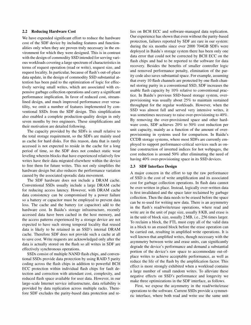
Host Interface PCIe 1.1x8Channel Count 44
Flash Chips per Channel 2Planes per Flash Chip 2
Channel Interface Asynchronous 40 MHzFlash Capacity per Channel 16 GB
NAND Type 25 nm MLCPage Size 8 KBBlock Size 2 MB
Table 3. Device configuration for both the Baidu SDF andthe Huawei Gen3.
lection. In the Huawei Gen3 data is striped over its 44 chan-nels with a striping unit size of 8 KB. The Intel 320 uses25 nm MLC NAND flash and the SATA 2.0 interface. TheIntel 320 has 10 channels, and 20 GB (12.5%) of its rawcapacity of 160 GB is reserved for internal use includinggarbage collection.
3.2 Experiments with MicrobenchmarksSDF is designed to deliver I/O service with high throughputand low latency to applications with high concurrency. Toreveal the storage devices’ performance, in the evaluationwe first generate synthetic workloads on the server. For SDFwe send requests to the SDF as a raw device, bypassing thekernel I/O stack. For the Intel and Huawei SSDs the requestsare sent to the respective devices via the Linux I/O stack.
In the experiments we first run microbenchmarks that is-sue random read requests of different sizes (8 KB, 16 KB,and 64 KB) and 8 MB write requests to each of the three de-vices. For SDF we use 44 threads—one for each channel—to exploit its hardware parallelism. For the other two devicesonly one thread is used because they expose only one chan-nel, and the thread issues asynchronous requests. For SDF allrequests are synchronously issued and the benchmarks issuerequests as rapidly as possible to keep all channels busy. Theresults are reported in Table 4. Because SDF does not allowwrites smaller than 8 MB we use only 8 MB writes in thetest.
To put SDF’s performance in perspective we need toknow the throughout limits imposed by the PCIe interfaceand the flash itself. The maximum PCIe throughputs when itis used for data read and write are 1.61 GB/s and 1.40 GB/s,respectively, and SDF’s aggregate flash raw read/write band-widths are 1.67 GB/s and 1.01 GB/s, respectively. From thetable we can see that SDF enables throughput close to thearchitectural limits: for read its 8 MB-request throughout of1.59 GB/s is 99% of the bandwidth limit imposed by thePCIe interface, and for write, 0.96 GB/s throughout is 94%of the flash’s raw bandwidth. Even for reads with requestsas small as 8 KB the throughout is 76% or more of the PCIebandwidth limit. The expensive erasure operation can reacha 40 GB/s throughput in SDF (not shown in the table).
0
200
400
600
800
1000
1200
1400
1600
4 8 12 16 20 24 28 32 36 40 44
Thro
ugh
pu
t (M
B/s
)
Channel Count(a)
0
100
200
300
400
500
600
700
800
900
1000
4 8 12 16 20 24 28 32 36 40 44Th
rou
ghp
ut
(MB
/s)
Channel Count(b)
Figure 7. Throughputs of SDF with sequential reads (a) andwrites (b) when different numbers of channels are used.
Though the Huawei Gen3 has the same number of chan-nels, type and count of flash chips, and FPGA controllerhardware, its throughput is consistently lower than that ofSDF. In particular, with a request size of 64 KB or smallerits throughput is substantially lower. In SDF, as long as a re-quest is not larger than 8 MB it is serviced by one channel.In contrast, in the Huawei Gen3 the logical address space isstriped over 44 channels with an 8 KB striping unit. A largerequest is split into multiple sub-requests, which are servicedin different channels. Accordingly, requested data has to besplit (for write) or merged (for read) in the request service,and each channel serves a larger number of smaller requests.This adds to the overhead and reduces throughput.
We also experimented with the SDF when only limitednumbers of channels are concurrently accessed, still witheach channel receiving requests from a dedicated thread.Figures 7(a) and 7(b) show the throughput of the SDF withsequential 8 MB read and write requests when different num-bers of channels are employed. As shown, the throughputincreases almost linearly with the number of channels be-fore the PCIe’s bandwidth limit or the flash’s raw bandwidthis reached, demonstrating that the SDF architecture scaleswell.
Because performance predictability can be important ina data center, especially for on-line service, we evaluate la-tency variation for write requests on the Huawei Gen3 and
Operations 8 KB Read 16 KB Read 64 KB Read 8 MB Read 8 MB WriteBaidu SDF (GB/s) 1.23 1.42 1.51 1.59 0.96
Huawei Gen3 (GB/s) 0.92 1.02 1.15 1.20 0.67Intel 320 (GB/s) 0.17 0.20 0.22 0.22 0.13
Table 4. Throughputs of the Baidu SDF, Huawei Gen3, and Intel 320 devices with different request sizes for read and writeoperations. Because the SDF’s write unit is 8 MB, only write throughputs for 8 MB are reported.
.
0
100
200
300
400
500
600
700
800
900
1 8
15
22
29
36
43
50
57
64
71
78
85
92
99
10
6
11
3
12
0
12
7
13
4
14
1
14
8
15
5
16
2
16
9
17
6
18
3
19
0
19
7
Late
ncy
(ms)
Time (# of Writes)
Huawei Gen3, 8MB Writes
0
500
1000
1500
2000
2500
3000
3500
4000
4500
1 8
15
22
29
36
43
50
57
64
71
78
85
92
99
10
6
11
3
12
0
12
7
13
4
14
1
14
8
15
5
16
2
16
9
17
6
18
3
19
0
19
7
Late
ncy
(ms)
Time (# of Writes)
Huawei Gen3, 8*44MB Writes
0
100
200
300
400
500
600
700
800
900
1 8
15
22
29
36
43
50
57
64
71
78
85
92
99
10
6
11
3
12
0
12
7
13
4
14
1
14
8
15
5
16
2
16
9
17
6
18
3
19
0
19
7
Late
ncy
(ms)
Time (# of Writes)
Baidu SDF, 8MB Erases and Writes
Figure 8. Latencies of write requests on the Huawei Gen3 and the Baidu SDF when writes with an aggregate total of 28 GBdata are in progress. The Huawei Gen3 serves write requests of either 8 MB or 352 MB. The Baidu SDF serves write requestsof 8 MB simultaneously on its 44 channels. By design these devices were almost full at the beginning of the experiments.
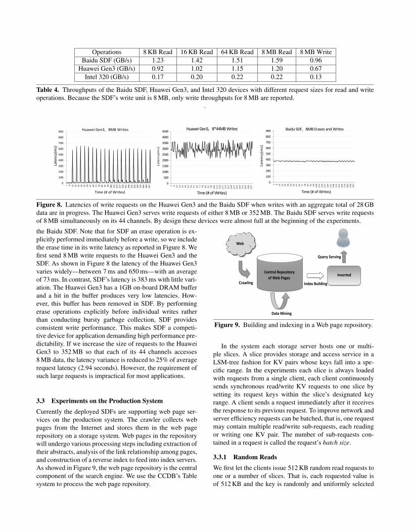
the Baidu SDF. Note that for SDF an erase operation is ex-plicitly performed immediately before a write, so we includethe erase time in its write latency as reported in Figure 8. Wefirst send 8 MB write requests to the Huawei Gen3 and theSDF. As shown in Figure 8 the latency of the Huawei Gen3varies widely—between 7 ms and 650 ms—with an averageof 73 ms. In contrast, SDF’s latency is 383 ms with little vari-ation. The Huawei Gen3 has a 1GB on-board DRAM bufferand a hit in the buffer produces very low latencies. How-ever, this buffer has been removed in SDF. By performingerase operations explicitly before individual writes ratherthan conducting bursty garbage collection, SDF providesconsistent write performance. This makes SDF a competi-tive device for application demanding high performance pre-dictability. If we increase the size of requests to the HuaweiGen3 to 352 MB so that each of its 44 channels accesses8 MB data, the latency variance is reduced to 25% of averagerequest latency (2.94 seconds). However, the requirement ofsuch large requests is impractical for most applications.
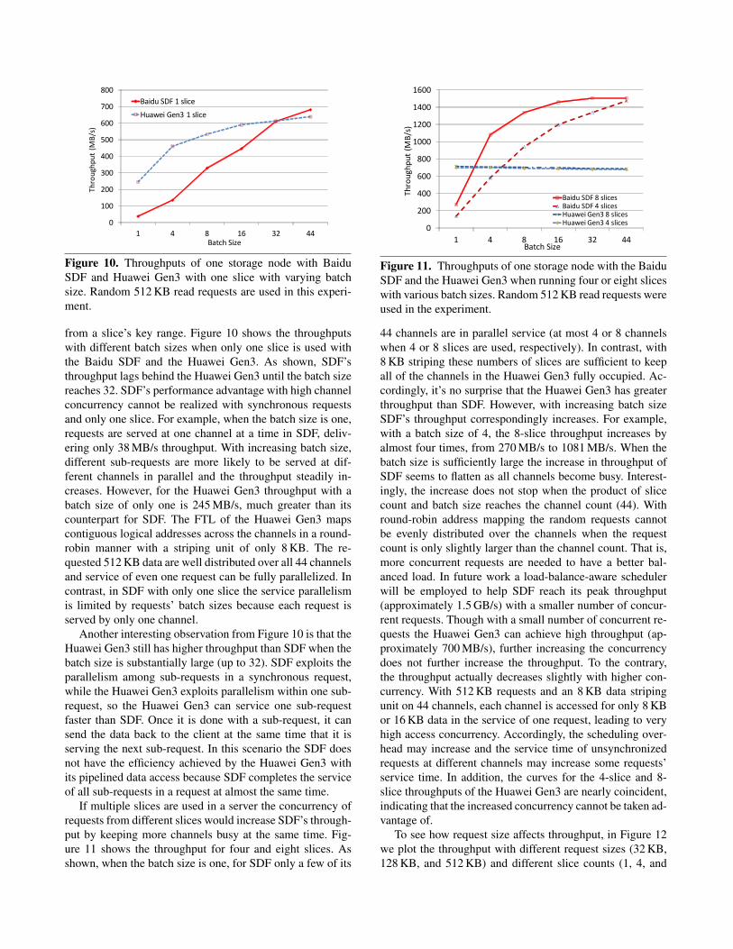
3.3 Experiments on the Production SystemCurrently the deployed SDFs are supporting web page ser-vices on the production system. The crawler collects webpages from the Internet and stores them in the web pagerepository on a storage system. Web pages in the repositorywill undergo various processing steps including extraction oftheir abstracts, analysis of the link relationship among pages,and construction of a reverse index to feed into index servers.As showed in Figure 9, the web page repository is the centralcomponent of the search engine. We use the CCDB’s Tablesystem to process the web page repository.
Index Building
Web
Crawling
Data Mining
Query Serving
Inverted
Index
Central Repository
of Web Pages
Figure 9. Building and indexing in a Web page repository.
In the system each storage server hosts one or multi-ple slices. A slice provides storage and access service in aLSM-tree fashion for KV pairs whose keys fall into a spe-cific range. In the experiments each slice is always loadedwith requests from a single client, each client continuouslysends synchronous read/write KV requests to one slice bysetting its request keys within the slice’s designated keyrange. A client sends a request immediately after it receivesthe response to its previous request. To improve network andserver efficiency requests can be batched, that is, one requestmay contain multiple read/write sub-requests, each readingor writing one KV pair. The number of sub-requests con-tained in a request is called the request’s batch size.
3.3.1 Random ReadsWe first let the clients issue 512 KB random read requests toone or a number of slices. That is, each requested value isof 512 KB and the key is randomly and uniformly selected
0
100
200
300
400
500
600
700
800
1 4 8 16 32 44
Baidu SDF 1 slice
Huawei Gen3 1 slice
Th
rou
ghp
ut
(MB
/s)
Batch Size
Figure 10. Throughputs of one storage node with BaiduSDF and Huawei Gen3 with one slice with varying batchsize. Random 512 KB read requests are used in this experi-ment.
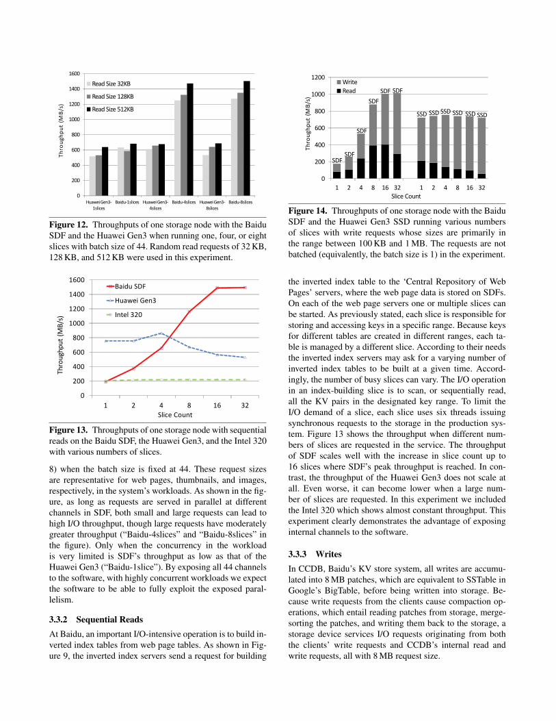
from a slice’s key range. Figure 10 shows the throughputswith different batch sizes when only one slice is used withthe Baidu SDF and the Huawei Gen3. As shown, SDF’sthroughput lags behind the Huawei Gen3 until the batch sizereaches 32. SDF’s performance advantage with high channelconcurrency cannot be realized with synchronous requestsand only one slice. For example, when the batch size is one,requests are served at one channel at a time in SDF, deliv-ering only 38 MB/s throughput. With increasing batch size,different sub-requests are more likely to be served at dif-ferent channels in parallel and the throughput steadily in-creases. However, for the Huawei Gen3 throughput with abatch size of only one is 245 MB/s, much greater than itscounterpart for SDF. The FTL of the Huawei Gen3 mapscontiguous logical addresses across the channels in a round-robin manner with a striping unit of only 8 KB. The re-quested 512 KB data are well distributed over all 44 channelsand service of even one request can be fully parallelized. Incontrast, in SDF with only one slice the service parallelismis limited by requests’ batch sizes because each request isserved by only one channel.
Another interesting observation from Figure 10 is that theHuawei Gen3 still has higher throughput than SDF when thebatch size is substantially large (up to 32). SDF exploits theparallelism among sub-requests in a synchronous request,while the Huawei Gen3 exploits parallelism within one sub-request, so the Huawei Gen3 can service one sub-requestfaster than SDF. Once it is done with a sub-request, it cansend the data back to the client at the same time that it isserving the next sub-request. In this scenario the SDF doesnot have the efficiency achieved by the Huawei Gen3 withits pipelined data access because SDF completes the serviceof all sub-requests in a request at almost the same time.
If multiple slices are used in a server the concurrency ofrequests from different slices would increase SDF’s through-put by keeping more channels busy at the same time. Fig-ure 11 shows the throughput for four and eight slices. Asshown, when the batch size is one, for SDF only a few of its
0
200
400
600
800
1000
1200
1400
1600
1 4 8 16 32 44
Baidu SDF 8 slicesBaidu SDF 4 slicesHuawei Gen3 8 slicesHuawei Gen3 4 slices
Thro
ugh
pu
t (M
B/s
)
Batch Size
Figure 11. Throughputs of one storage node with the BaiduSDF and the Huawei Gen3 when running four or eight sliceswith various batch sizes. Random 512 KB read requests wereused in the experiment.
44 channels are in parallel service (at most 4 or 8 channelswhen 4 or 8 slices are used, respectively). In contrast, with8 KB striping these numbers of slices are sufficient to keepall of the channels in the Huawei Gen3 fully occupied. Ac-cordingly, it’s no surprise that the Huawei Gen3 has greaterthroughput than SDF. However, with increasing batch sizeSDF’s throughput correspondingly increases. For example,with a batch size of 4, the 8-slice throughput increases byalmost four times, from 270 MB/s to 1081 MB/s. When thebatch size is sufficiently large the increase in throughput ofSDF seems to flatten as all channels become busy. Interest-ingly, the increase does not stop when the product of slicecount and batch size reaches the channel count (44). Withround-robin address mapping the random requests cannotbe evenly distributed over the channels when the requestcount is only slightly larger than the channel count. That is,more concurrent requests are needed to have a better bal-anced load. In future work a load-balance-aware schedulerwill be employed to help SDF reach its peak throughput(approximately 1.5 GB/s) with a smaller number of concur-rent requests. Though with a small number of concurrent re-quests the Huawei Gen3 can achieve high throughput (ap-proximately 700 MB/s), further increasing the concurrencydoes not further increase the throughput. To the contrary,the throughput actually decreases slightly with higher con-currency. With 512 KB requests and an 8 KB data stripingunit on 44 channels, each channel is accessed for only 8 KBor 16 KB data in the service of one request, leading to veryhigh access concurrency. Accordingly, the scheduling over-head may increase and the service time of unsynchronizedrequests at different channels may increase some requests’service time. In addition, the curves for the 4-slice and 8-slice throughputs of the Huawei Gen3 are nearly coincident,indicating that the increased concurrency cannot be taken ad-vantage of.
To see how request size affects throughput, in Figure 12we plot the throughput with different request sizes (32 KB,128 KB, and 512 KB) and different slice counts (1, 4, and
0
200
400
600
800
1000
1200
1400
1600
Huawei Gen3-1slices
Baidu-1slices Huawei Gen3-4slices
Baidu-4slices Huawei Gen3-8slices
Baidu-8slices
Read Size 32KB
Read Size 128KB
Read Size 512KB
Th
rou
gh
pu
t (M
B/s
)
Figure 12. Throughputs of one storage node with the BaiduSDF and the Huawei Gen3 when running one, four, or eightslices with batch size of 44. Random read requests of 32 KB,128 KB, and 512 KB were used in this experiment.
0
200
400
600
800
1000
1200
1400
1600
1 2 4 8 16 32
Baidu SDF
Huawei Gen3
Intel 320
Thro
ugh
pu
t (M
B/s
)
Slice Count
Figure 13. Throughputs of one storage node with sequentialreads on the Baidu SDF, the Huawei Gen3, and the Intel 320with various numbers of slices.
8) when the batch size is fixed at 44. These request sizesare representative for web pages, thumbnails, and images,respectively, in the system’s workloads. As shown in the fig-ure, as long as requests are served in parallel at differentchannels in SDF, both small and large requests can lead tohigh I/O throughput, though large requests have moderatelygreater throughput (“Baidu-4slices” and “Baidu-8slices” inthe figure). Only when the concurrency in the workloadis very limited is SDF’s throughput as low as that of theHuawei Gen3 (“Baidu-1slice”). By exposing all 44 channelsto the software, with highly concurrent workloads we expectthe software to be able to fully exploit the exposed paral-lelism.
3.3.2 Sequential ReadsAt Baidu, an important I/O-intensive operation is to build in-verted index tables from web page tables. As shown in Fig-ure 9, the inverted index servers send a request for building
SDFSDF
SDF
SDF
SDF SDF
SSD SSD SSD SSD SSD SSD
0
200
400
600
800
1000
1200
1 2 4 8 16 32 1 2 4 8 16 32
Write
Read
Slice Count
Th
rou
ghp
ut
(MB
/s)
Figure 14. Throughputs of one storage node with the BaiduSDF and the Huawei Gen3 SSD running various numbersof slices with write requests whose sizes are primarily inthe range between 100 KB and 1 MB. The requests are notbatched (equivalently, the batch size is 1) in the experiment.
the inverted index table to the ‘Central Repository of WebPages’ servers, where the web page data is stored on SDFs.On each of the web page servers one or multiple slices canbe started. As previously stated, each slice is responsible forstoring and accessing keys in a specific range. Because keysfor different tables are created in different ranges, each ta-ble is managed by a different slice. According to their needsthe inverted index servers may ask for a varying number ofinverted index tables to be built at a given time. Accord-ingly, the number of busy slices can vary. The I/O operationin an index-building slice is to scan, or sequentially read,all the KV pairs in the designated key range. To limit theI/O demand of a slice, each slice uses six threads issuingsynchronous requests to the storage in the production sys-tem. Figure 13 shows the throughput when different num-bers of slices are requested in the service. The throughputof SDF scales well with the increase in slice count up to16 slices where SDF’s peak throughput is reached. In con-trast, the throughput of the Huawei Gen3 does not scale atall. Even worse, it can become lower when a large num-ber of slices are requested. In this experiment we includedthe Intel 320 which shows almost constant throughput. Thisexperiment clearly demonstrates the advantage of exposinginternal channels to the software.
3.3.3 WritesIn CCDB, Baidu’s KV store system, all writes are accumu-lated into 8 MB patches, which are equivalent to SSTable inGoogle’s BigTable, before being written into storage. Be-cause write requests from the clients cause compaction op-erations, which entail reading patches from storage, merge-sorting the patches, and writing them back to the storage, astorage device services I/O requests originating from boththe clients’ write requests and CCDB’s internal read andwrite requests, all with 8 MB request size.
In the experiment each client continuously sends syn-chronous write requests to a slice. Figure 14 shows the readand write throughput of the Baidu SDF and the HuaweiGen3. Because only the compaction operation incurs reads,the read throughput shown in Figure 14 represents the in-tensity of the internal data cleanup operation. At the begin-ning of the experiment, all patches on the storage have beensorted. Therefore, the volume of new written data is corre-lated to the demand on the compaction operation. Requestsfrom the clients take priority over compaction-incurred re-quests.
As shown, SDF’s throughput continues to increase un-til the slice count reaches 16 where the throughput peaksat around 1 GB/s. When the slice count is small, the lim-ited concurrency leads to SDF’s low throughout in serv-ing client write requests. Accordingly, the compaction in-tensity, indicated by the read throughput, is also low. How-ever, SDF can take good advantage of high concurrencywhere its peak throughput reaches a value between the de-vice’s peak write throughput (approximately 0.95 GB/s) andits peak read throughput (approximately 1.50 GB/s). Con-sidering the presence of erasure operations, SDF achievesexcellent peak throughput. When the slice count increasesfrom 16 to 32 the percentage of the throughput attributableto reads is reduced because the increased demand from theclients’ write requests pushes the compaction load lower.In contrast, the Huawei Gen3 exploits channel parallelismfor individual 8 MB-patch accesses so it can achieve muchhigher throughout when the slice count is small, but itsthroughput does not increase with increasing slice count.Furthermore, because of its limited throughput, the HuaweiGen3 compaction throughput decreases with increasing slicecount. With 32 slices the throughput is less than 15% of theaggregate throughput, indicating that most of new writtendata is left unsorted. This would significantly compromiseperformance of subsequent read requests from clients.
4. Related WorkWe organize our discussion of related work as addressing thereduction of the overhead of random writes, the support ofhigh I/O concurrency, and the reduction of access latency.
4.1 Reducing the Overhead of Random WritesThough SSD’s random-write throughput is higher thanthat of hard disks, it is much less than its sequential-write throughput [15]. Even for modern high-end SSDs thethroughput of random write is only about 1/10 to 1/7 of se-quential writes [15]. Further, random writes can cause inter-nal fragmentation and lead to performance degradation by anorder of magnitude and can significantly reduce lifetime ofthe device because write amplification is much greater thanfor sequential write [15]. To address these issues researchershave tried to transform random writes to sequential writes ateither the file system level or at the FTL level.
At the file system level, Min proposed a log-structuredfile system (SFS) to transform random writes in the filesystem into sequential writes at the SSD [15]. Other log-based file systems, such as JFFS2 [19], YAFFS2 [4], andUBIFS [3], are designed by considering NAND flash char-acteristics and are used widely, especially in mobile and em-bedded domains. The log-based file system can eliminaterandom writes to the flash memory. By requiring a largewrite unit, SDF essentially forces the software to batch writedata as a log. On top of SDF, at Baidu a user-space dis-tributed log-based storage system is implemented. It knowsthe data types and how actively particular data is accessed,so it can implement a more intelligent block cleaning schemecompared to a log-based file system.
At the FTL level some researchers have used a log bufferat the FTL level to reduce the overhead of random writes.Kawaguchi et al. proposed a flash memory driver that uses alog-based FTL and provides a block interface to the flash thatsequentially writes data to the flash memory in a way sim-ilar to log-structured file system [11]. Kim et al. proposedBAST, a hybrid FTL scheme [12]. It uses page-level map-ping for random writes and block-level mapping for sequen-tial writes [13]. The FAST FTL improves on BAST with aflexible address mapping in the log buffer to improve spaceutilization. Some FTLs reduce the overhead caused by ran-dom writes by considering data access characteristics. LASTreduces the garbage collection overhead by exploiting datalocality [14]. CAFTL reduces write traffic to the flash mem-ory by eliminating duplicate writes and redundant data [7].Both the file-system-level and the FTL-level efforts cannotcompletely eliminate the garbage collection overhead causedby random writes. SDF eliminates random writes by set-ting the write size to a multiple of the size of NAND phys-ical erase block. Thus SDF’s FTL does not need to conductgarbage collection, and write amplification ratio is kept atone.
4.2 Supporting High I/O ConcurrencySSDs may be deployed in an environment with a large num-ber of applications or threads simultaneously issuing re-quests to them, that is, with workloads of high concurrency,and it is necessary to exploit parallelism at multiple layersof the I/O stack to achieve high throughput. Here there arethree layers that are most relevant. The first is the Linux I/Osubsystem, which includes VFS, the file system, the genericblock layer, the scheduler layer, the SCSI mid-layer, andthe SATA/SAS translation layer. The second is the devicedriver, which includes command queues, interrupt handlers,and a hardware register interface. The third is in the SSDitself, including the host interface, on-device DRAM, inter-nal data paths, and multiple NAND channels. Many pre-vious works have investigated parallelism at each of thesethree layers. Seppanen et al. suggest exploiting the paral-lelism of the Linux I/O subsystem with multiple AIO re-quests or by using multiple threads issuing synchronous I/O

requests [18]. To take advantage of this parallelism appli-cations need to use AIO or be multi-threaded, necessitatingmodification of legacy programs. SDF uses multiple threadswith synchronous I/O requests to exploit Linux I/O subsys-tem parallelism because synchronous I/O is easier to imple-ment and is compatible with many legacy applications.
Modern drivers support multiple deep command queuessuch as NCQ [18] for SATA II, and NVM Express [2] whichis designed to address the challenges of system scalability.NVM Express provides optimized command issuance mech-anisms and multiple deep queues. Using multiple queues cansupport concurrent operations and help to improve scala-bility. Moreover, when the queues are operated on multipleCPU cores, interrupt handling can be more efficient. Follow-ing the same principle, SDF creates a queue for each chan-nel. Hahn et al. consider issues with the request schedulingwhen SSD channels are exposed [10]. We leave studies onintelligent request scheduling on SDF as future work.
Chen et al. investigated the performance implications ofSSD’s internal parallelism [6]. As we have demonstrated, theaggregate channel-level bandwidth of a commodity SSD canbe greater than that made available at the host interface bya significant factor, implying that the internal parallelism inan SSD is far from fully exploited. By exposing flash chan-nels to applications, SDF can effectively increase availablechannel-level parallelism, and applications can manage datalayout among channels or among planes in a channel.
4.3 Reducing Access latencyFoong et al. break down the latency overhead for a request atthe granularity of the layers of the I/O stack [8]. As reported,the Linux I/O subsystem takes about 9100 CPU cycles toissue a request to the device and about 21900 CPU cycles toprocess I/O completion. The total time spent in the Linux I/Osubsystem for one I/O request is about 12.9µs on a 2.4GHzmainstream server processor. In contrast, reading a NANDpage from the cell to the host interface takes only about75µs for 25nm MLC flash [1], so the software I/O stack isresponsible for about 17% of the total request service timefor a page read request, which we regards as substantial. Oursolution is to simply bypass the Linux I/O subsystem andtraditional driver layer, using instead an ultra-light-weightuser-space interface and thin driver. The SDF driver providesa register interface and a message signaled interrupt handler.Thus the software layer of SDF is able to significantly reducethe software overhead compared with conventional systems.
5. Conclusions and Future WorkIn the paper we present SDF, a software-defined SSD, forweb-scale Internet storage infrastructures. SDF is a high-performance and low-cost SSD architecture with high uti-lization of raw bandwidth and storage space and with pre-dictable performance. It has successfully replaced traditionalSSDs at Baidu’s Internet storage infrastructure with 3000
SDFs deployed and more scheduled. SDF’s success derivesfrom its hardware-software co-design. In SDF, the hardwareexposes the internal channels to the applications throughcustomized FTL controllers. Dovetailing with the hard-ware design, the software layer enforces large-granularitywrites and provides primitive and light-weight functionali-ties through kernel bypass. Our experimental measurementsshow that SDF can deliver about 95% of the raw flash band-width and provide 99% of the flash capacity for user data.SDF increases the I/O bandwidth by 3 times and reducesper-GB hardware cost by 50% on average compared withBaidu’s commodity-SSD-based system.
The success of the SDF at Baidu is highly dependenton two key workload characteristics that we believe arealso prevalent in most data centers supporting Internet ser-vices. One is large sequential writes. Because write requestshave been mostly served in log-structured storage systems,such as Google’s LevelDB and Facebook’s Haystack, SDF’sperformance advantage on write can be realized withoutre-writing or re-structuring existing software. The otheris high concurrency for exploiting SDF’s exposed chan-nels. Because Internet service is mostly multi-threaded andtransaction-based for supporting millions of users, high con-currency in the I/O workload is expected and is the reality inmost cases.
The Baidu SDF research is ongoing on multiple fronts.First, as previously described we will implement a load-balance-aware scheduler to help SDF reach its peak through-put with a smaller number of concurrent requests. Also, tofurther pursue our hardware/software co-design approach,we intend to further investigate the possibility of “movingcompute to the storage,” that is, integrating specialized com-putational functionality into the storage devices themselvesto minimize I/O traffic; an initial success has already beenreported [17]. Finally, recognizing that flash memory has fi-nite write endurance, we believe that that it would be bothpossible and useful to incorporate, and expose, a data relia-bility model for flash memory in our infrastructure.
AcknowledgmentsThe SDF project has benefited greatly from constructiveinput from many engineers and interns at Baidu, in particularGuangjun Xie, Wei Qi, Hao Tang, and Bo Peng. We wouldlike to thank Kei Davis for constructive input on the finalcomposition of this paper. We are also thankful to JasonCong for his support and suggestions on the paper.
References[1] “Micron 25nm MLC Product Datasheet.”
http://www.micron.com.
[2] “NVMe: Non-volatile Memory Express.”http://www.nvmexpress.org/.
[3] “UBIFS: Unsorted Block Image File System.”http://www.linux-mtd.infradead.org/doc/ubifs.html/.

[4] “YFFS: Yet Another Flash File System.”http://www.yaffs.net/.
[5] F. Chang, J. Dean, S. Ghemawat, W. C. Hsieh, D. A. Wallach,M. Burrows, T. Chandra, A. Fikes, and R. E. Gruber.“Bigtable: A Distributed Storage System for StructuredData.” In Seventh Symposium on Operating System Designand Implementation, 2006.
[6] F. Chen, R. Lee, and X. Zhang. “Essential Roles of ExploitingInternal Parallelism of Flash Memory based Solid State Drivesin High-speed Data Processing.” In IEEE 17th InternationalSymposium on High Performance Computer Architecture,2011.
[7] F. Chen, T. Luo, and X. Zhang, “CAFTL: A Content-Aware Flash Translation Layer Enhancing the Lifespan ofFlash Memory based Solid State Drives.” In 9th USENIXConference on File and Storage Technologies, 2011.
[8] A. Foong, B. Veal, and F. Hady. “Towards SSD-readyEnterprise Platforms.” In 1st International Workshop onAccelerating Data Management Systems Using ModernProcessor and Storage Architectures, 2010.
[9] S. Ghemawat, H. Gobioff, and S.-T. Leung. “The GoogleFile System” In 19th ACM Symposium on Operating SystemsPrinciples, 2003.
[10] S. S. Hahn, S. Lee, and J. Kim. “SOS: Software-based Out-of-order Scheduling for High-performance NAND Flash-basedSSDs.” In IEEE 29th Symposium on Mass Storage Systemsand Technologies, 2013.
[11] A. Kawaguchi, S. Nishioka, and H. Motoda. “A Flash-memory based File System.” In Winter USENIX TechnicalConference, 1995.
[12] J. Kim, J. M. Kim, S. H. Noh, S. L. Min, and Y. Cho. “ASpace-efficient Flash Translation Layer for Compact-flashSystems.” In IEEE Transactions on Consumer Electronics,2002.
[13] S. W. Lee, D. J. Park, T. S. Chung, D. H. Lee, S. Park, andH. J. Song. “A Log Buffer-based Flash Translation LayerUsing Fully-associative Sector Translation.” In Trans. onEmbedded Computing Systems, 2007.
[14] S. Lee, D. Shin, Y. J. Kim, and J. Kim. “LAST: Locality-awareSector Translation for NAND Flash Memory-based StorageSystems.” In SIGOPS Operating Systems Review, 2008.
[15] C. Min, K. Kim, H. Cho, S. Lee, and Y. Eom. “SFS: RandomWrite Considered Harmful in Solid State Drives,” In 10thUSENIX Conference on File and Storage Technologies, 2012.
[16] P. O’Neil, E. Cheng, D. Gawlick, and E. O’Neil. “TheLog-structured Merge-tree (LSM-tree).” In Acta Informatica33(4):351-385, 1996.
[17] J. Ouyang, S. Lin, Z. Hou, P. Wang, Y. Wang, and G. Sun.“Active SSD Design for Energy-efficiency Improvement ofWeb-scale Data Analysis.” In International Symposium onLow Power Electronics and Design, 2013.
[18] E. Seppanen, M. T. O’Keefe, and D. J. Lilja. “High Perfor-mance Solid State Storage under Linux.” In IEEE 26th Sym-posium on Mass Storage Systems and Technologies, 2010.
[19] D. Woodhouse. “JFFS: The Journaling Flash File System.” InOttowa Linux symposium, 2012.


![[Flash] Modul Flash Sadana Production](https://static.fdocuments.us/doc/165x107/5571f80f49795991698c8ba3/flash-modul-flash-sadana-production.jpg)