SD2504SN - WaterFurnace
27
500RO11 Outdoor Split Geothermal Heat Pump 2-6 ton (dual capacity) Submittal Data English Language/IP Units SD2504SN 04/17
Transcript of SD2504SN - WaterFurnace

500RO11Outdoor Split Geothermal Heat Pump
2-6 ton (dual capacity)
Submittal Data
English Language/IP Units
SD2504SN 04/17

WaterFurnace works continually to improve its products. As a result, the design and specifi cations of each product at the time of order may be changed without notice. Please contact WaterFurnace at 1-888-929-2837 for latest design and specifi cations. Purchaser’s approval of this data set signifi es that the equipment is acceptable under the provisions of the job specifi cation. Statements and other information contained herein are not express warranties and do not form the basis of any bargain between the parties, but are merely WaterFurnace’s opinion or commendation of its products. The latest version of this document is available at www.waterfurnace.com.
Contractor: P.O.:
Engineer:
Project Name: Unit Tag:
SD2504SN 04/17 2 Page _____ of ____z
5 Series 500RO112-6 Ton 60Hz
Model Nomenclature
All 5 Series Series product is safety listed under UL1995 thru ETL and performance listed with AHRI in accordance with standard 13256-1. The 5 Series is also ENERGY STAR® rated.
N D S 049 * 1 0 A C N N 0 A1 2 3 4-6 7 8 9 10 11 12 13 14 15
ModelN – 5 Series
StageD – Dual Capacity
Cabinet ConfigurationS – Outdoor Split
Unit Capacity026, 038, 049, 064, 072
Vintage* - Factory Use Only
Voltage1 – 208-230/60/1
Hot Water Generation 0 - None
IntelliStart OptionN – NoneA - IntelliStart
ControlsA – AuroraTM Base Control (ABC)B – Aurora Advanced Control
(ABC & AXB)C – Aurora Performance Package2
D – Aurora Performance andRefrigeration Package2
Future Options0 – None
Future OptionsN – None
Future OptionsN – None
Water Coax OptionC – CopperN – CuproNickel
Flow CenterA – NoneB – FC1-GL Flow Center1
C – FC2-GL Flow Center
Rev.: 1/24/2017
N16
Note:1 – FC1-GL Not Available on 064-072 Units2 – Performance Package just includes water temperature monitoring.
WaterFurnace works continually to improve its products. As a result, the design and specifi cations of each product at the time of order may be changed without notice. Please contact WaterFurnace at 1-888-929-2837 for latest design and specifi cations. Purchaser’s approval of this data set signifi es that the equipment is acceptable under the provisions of the job specifi cation. Statements and other information contained herein are not express warranties and do not form the basis of any bargain between the parties, but are merely WaterFurnace’s opinion or commendation of its products. The latest version of this document is available at www.waterfurnace.com.
Contractor: P.O.: Engineer:
Project Name: Unit Tag:
SD2504SN 04/17 3 Page _____ of ____z
5 Series 500RO112-6 Ton 60Hz
AHRI Data
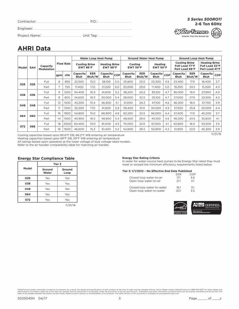
Cooling capacities based upon 80.6°F DB, 66.2°F WB entering air temperatureHeating capacities based upon 68°F DB, 59°F WB entering air temperatureAll ratings based upon operation at the lower voltage of dual voltage rated models.Refer to the air handler compatibility table for matching air handler.
11/21/16
Energy Star Compliance Table
Model
Tier 3
Ground Water
Ground Loop
026 Yes Yes
038 Yes Yes
049 Yes Yes
064 Yes Yes
072 Yes Yes
11/21/16
Energy Star Rating CriteriaIn order for water-source heat pumps to be Energy Star rated they must meet or exceed the minimum efficiency requirements listed below. Tier 3: 1/1/2012 – No Effective End Date Published EER COP
Closed loop water-to-air 17.1 3.6Open loop water-to-air 21.1 4.1 Closed loop water-to-water 16.1 3.1Open loop water-to-water 20.1 3.5
Model SAHCapacity
Modulation
Flow Rate
Water Loop Heat Pump Ground Water Heat Pump Ground Loop Heat Pump
Cooling Brine EWT 86°F
Heating Brine EWT 68°F
Cooling EWT 59°F
Heating EWT 50°F
Cooling Brine Full Load 77°F Part Load 68°F
Heating Brine Full Load 32°F Part Load 41°F
gpm cfm Capacity
Btuh EER
Btuh/W Capacity
Btuh COP
Capacity Btuh
EER Btuh/W
Capacity Btuh
COP Capacity
Btuh EER
Btuh/W Capacity
Btuh COP
026 026Full 8 850 22,500 15.0 28,100 5.0 25,800 23.0 23,300 4.6 23,400 17.5 18,400 3.7
Part 7 750 17,400 17.0 21,200 6.0 20,000 29.0 17,400 5.0 19,200 24.5 15,500 4.3
038 036Full 9 1200 34,400 16.3 41,600 5.2 38,200 24.2 35,100 4.7 36,000 19.0 27,900 4.0
Part 8 800 24,600 18.3 30,000 5.4 28,000 32.5 25,100 4.7 27,000 27.0 22,500 4.2
049 048Full 12 1500 43,200 15.4 56,300 5.1 51,000 24.2 47,100 4.6 46,300 18.0 37,700 3.9
Part 11 1300 32,500 17.0 41,600 5.9 39,400 31.0 34,000 4.9 37,500 25.8 30,000 4.4
064 060Full 16 1800 54,800 15.0 66,900 4.8 63,200 22.5 56,000 4.4 57,400 17.0 45,200 3.7
Part 14 1500 40,900 16.5 48,900 5.4 48,500 29.0 40,100 4.6 46,300 24.5 35,600 4.1
072 066Full 18 2000 60,400 14.0 81,000 4.5 70,000 22.0 67,500 4.1 62,800 16.0 53,500 3.5
Part 16 1600 46,600 15.3 61,400 5.2 54,600 26.5 50,800 4.2 51,900 22.0 45,300 3.9

WaterFurnace works continually to improve its products. As a result, the design and specifi cations of each product at the time of order may be changed without notice. Please contact WaterFurnace at 1-888-929-2837 for latest design and specifi cations. Purchaser’s approval of this data set signifi es that the equipment is acceptable under the provisions of the job specifi cation. Statements and other information contained herein are not express warranties and do not form the basis of any bargain between the parties, but are merely WaterFurnace’s opinion or commendation of its products. The latest version of this document is available at www.waterfurnace.com.
Contractor: P.O.: Engineer:
Project Name: Unit Tag:
SD2504SN 04/17 4 Page _____ of ____z
5 Series 500RO112-6 Ton 60Hz
Dimensional Data
L
A
C
B
K
J
H
F
G
DE
TOP VIEW
FRONT VIEW
SIDE VIEW
SIDE VIEWREAR VIEW
Suction Line Connection
Water In Water Out
Liquid Line Connection
Cabinet Dimensions and Refrigerant Piping Connections
Model A B C D E F G H J K L
026 thru 072in 36.0 23.9 26.7 5.4 6.0 8.2 10.8 14.0 9.0 20.2 7.2
[cm] [91.4] [60.7] [67.8] [13.7] [15.2] [20.8] [27.4] [35.6] [22.9] [51.3] [18.3]
WaterFurnace works continually to improve its products. As a result, the design and specifi cations of each product at the time of order may be changed without notice. Please contact WaterFurnace at 1-888-929-2837 for latest design and specifi cations. Purchaser’s approval of this data set signifi es that the equipment is acceptable under the provisions of the job specifi cation. Statements and other information contained herein are not express warranties and do not form the basis of any bargain between the parties, but are merely WaterFurnace’s opinion or commendation of its products. The latest version of this document is available at www.waterfurnace.com.
Contractor: P.O.: Engineer:
Project Name: Unit Tag:
SD2504SN 04/17 5 Page _____ of ____z
5 Series 500RO112-6 Ton 60Hz
Electrical Data
Physical Data
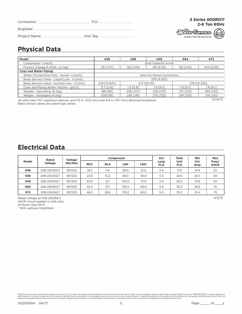
All units have TXV expansion devices, and 1/2 in. [12.2 mm] and 3/4 in. [19.1 mm] electrical knockouts. Brass service valves are sweat type valves.
Model 026 038 049 064 072
Compressor (1 each) Dual Capacity Scroll
Factory Charge R-410A, oz [kg] 52 [1.47] 56 [1.59] 90 [2.55] 92 [2.61] 104 [2.95]
Coax and Water Piping
Water Connections Size - Swivel- in [mm] GeoLink Swivel Connectors
Brass Service Valve - Liquid Line - in [mm] 3/8 [9.525]
Brass Service Valve - Suction Line - in [mm] 5/8 [15.875] 3/4 [19.05] 7/8 [22.225]
Coax and Piping Water Volume - gal [l] 0.7 [2.6] 1.3 [4.9] 1.6 [6.1] 1.6 [6.1] 1.6 [6.1]
Weight - Operating, lb [kg] 189 [86] 236 [107] 250 [113] 271 [123] 290 [132]
Weight - Packaged, lb [kg] 209 [95] 256 [116] 270 [122] 291 [132] 310 [141]
5/24/13
ModelRated
VoltageVoltageMin/Max
Compressor ExtLoopFLA
TotalUnitFLA
MinCircAmp
MaxFuse/HACRMCC RLA LRA LRA*
026 208-230/60/1 187/253 18.2 11.6 58.3 21.0 5.4 17.0 19.9 30
038 208-230/60/1 187/253 23.8 15.2 83.0 30.0 5.4 20.6 24.4 40
049 208-230/60/1 187/253 33.0 21.1 104.0 37.0 5.4 26.5 31.8 50
064 208-230/60/1 187/253 42.3 27.1 152.9 54.0 5.4 32.5 39.3 70
072 208-230/60/1 187/253 46.3 29.6 179.2 63.0 5.4 35.0 42.4 75
4/3/13Rated voltage of 208-230/60/1.HACR circuit breaker in USA only.All fuses Class RK-5* With optional IntelliStart
WaterFurnace works continually to improve its products. As a result, the design and specifi cations of each product at the time of order may be changed without notice. Please contact WaterFurnace at 1-888-929-2837 for latest design and specifi cations. Purchaser’s approval of this data set signifi es that the equipment is acceptable under the provisions of the job specifi cation. Statements and other information contained herein are not express warranties and do not form the basis of any bargain between the parties, but are merely WaterFurnace’s opinion or commendation of its products. The latest version of this document is available at www.waterfurnace.com.
Contractor: P.O.: Engineer:
Project Name: Unit Tag:
SD2504SN 04/17 6 Page _____ of ____z
5 Series 500RO112-6 Ton 60Hz
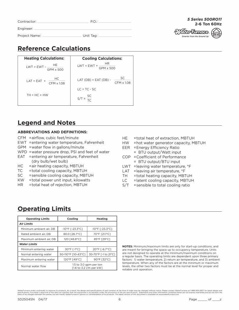
Reference Calculations
Heating Calculations: Cooling Calculations:
LWT = EWT +
LAT (DB) = EAT (DB) -
LC = TC - SC
S/T =
HR
GPM x 500
SC
CFM x 1.08
SC
TC
LWT = EWT -
LAT = EAT +
TH = HC + HW
HE
GPM x 500
HC
CFM x 1.08
Legend and NotesABBREVIATIONS AND DEFINITIONS:
CFM = airfl ow, cubic feet/minuteEWT = entering water temperature, FahrenheitGPM = water fl ow in gallons/minuteWPD = water pressure drop, PSI and feet of waterEAT = entering air temperature, Fahrenheit (dry bulb/wet bulb)HC = air heating capacity, MBTUHTC = total cooling capacity, MBTUHSC = sensible cooling capacity, MBTUHKW = total power unit input, kilowattsHR = total heat of rejection, MBTUH
HE = total heat of extraction, MBTUHHW = hot water generator capacity, MBTUHEER = Energy Effi ciency Ratio = BTU output/Watt inputCOP = Coeffi cient of Performance = BTU output/BTU inputLWT = leaving water temperature, °FLAT = leaving air temperature, °FTH = total heating capacity, MBTUHLC = latent cooling capacity, MBTUHS/T = sensible to total cooling ratio
Operating Limits Cooling Heating
Air Limits
Minimum ambient air, DB -10°F [-23.3°C] -10°F [-23.3°C]
Rated ambient air, DB 80.0 [26.7°C] 70°F [21.1°C]
Maximum ambient air, DB 120 [48.8°C] 85°F [29°C]
Water Limits
Minimum entering water 30°F [-1°C] 20°F [-6.7°C]
Normal entering water 50-110°F [10-43°C] 30-70°F [-1 to 21°C]
Maximum entering water 120°F [49°C] 90°F [32°C]
Normal water flow1.5 to 3.0 gpm per ton[1.6 to 3.2 l/m per kW]
Operating Limits
NOTES: Minimum/maximum limits are only for start-up conditions, and are meant for bringing the space up to occupancy temperature. Units are not designed to operate at the minimum/maximum conditions on a regular basis. The operating limits are dependent upon three primary factors: 1) water temperature, 2) return air temperature, and 3) ambient temperature. When any of the factors are at the minimum or maximum levels, the other two factors must be at the normal level for proper and reliable unit operation.

WaterFurnace works continually to improve its products. As a result, the design and specifi cations of each product at the time of order may be changed without notice. Please contact WaterFurnace at 1-888-929-2837 for latest design and specifi cations. Purchaser’s approval of this data set signifi es that the equipment is acceptable under the provisions of the job specifi cation. Statements and other information contained herein are not express warranties and do not form the basis of any bargain between the parties, but are merely WaterFurnace’s opinion or commendation of its products. The latest version of this document is available at www.waterfurnace.com.
Contractor: P.O.: Engineer:
Project Name: Unit Tag:
SD2504SN 04/17 7 Page _____ of ____z
5 Series 500RO112-6 Ton 60Hz
Correction Factor Tables
Heating Capacity Corrections
Ent Air DB °FHeating Corrections
Htg Cap Power Heat of Ext
45 1.062 0.739 1.158
50 1.050 0.790 1.130
55 1.037 0.842 1.096
60 1.025 0.893 1.064
65 1.012 0.945 1.030
68 1.005 0.976 1.012
70 1.000 1.000 1.000
75 0.987 1.048 0.970
80 0.975 1.099 0.930
1/5/17
Air Flow Corrections (Dual Capacity Part Load)Airflow Cooling Heating
cfm Per Ton of Clg
% of Nominal Total Cap Sens Cap Power Heat of Rej Htg Cap Power Heat of Ext
240 60 0.922 0.778 0.956 0.924 0.943 1.239 0.879
275 69 0.944 0.830 0.962 0.944 0.958 1.161 0.914
300 75 0.957 0.866 0.968 0.958 0.968 1.115 0.937
325 81 0.970 0.900 0.974 0.970 0.977 1.075 0.956
350 88 0.982 0.933 0.981 0.980 0.985 1.042 0.972
375 94 0.991 0.968 0.991 0.991 0.993 1.018 0.988
400 100 1.000 1.000 1.000 1.000 1.000 1.000 1.000
425 106 1.007 1.033 1.011 1.008 1.007 0.990 1.010
450 113 1.013 1.065 1.023 1.015 1.012 0.987 1.018
475 119 1.017 1.099 1.037 1.022 1.018 0.984 1.025
500 125 1.020 1.132 1.052 1.027 1.022 0.982 1.031
520 130 1.022 1.159 1.064 1.030 1.025 0.979 1.034
1/5/17
Air Flow Corrections (Dual Capacity Full Load and Single Speed)Airflow Cooling Heating
cfm Per Ton of Clg
% of Nominal Total Cap Sens Cap Power Heat of Rej Htg Cap Power Heat of Ext
240 60 0.922 0.786 0.910 0.920 0.943 1.150 0.893
275 69 0.944 0.827 0.924 0.940 0.958 1.105 0.922
300 75 0.959 0.860 0.937 0.955 0.968 1.078 0.942
325 81 0.971 0.894 0.950 0.967 0.977 1.053 0.959
350 88 0.982 0.929 0.964 0.978 0.985 1.031 0.973
375 94 0.992 0.965 0.982 0.990 0.993 1.014 0.988
400 100 1.000 1.000 1.000 1.000 1.000 1.000 1.000
425 106 1.007 1.034 1.020 1.010 1.007 0.990 1.011
450 113 1.012 1.065 1.042 1.018 1.013 0.983 1.020
475 119 1.017 1.093 1.066 1.026 1.018 0.980 1.028
500 125 1.019 1.117 1.092 1.033 1.023 0.978 1.034
520 130 1.020 1.132 1.113 1.038 1.026 0.975 1.038
1/5/17
Cooling Capacity Corrections
Entering Air WB °F
TotalClg Cap
Sensible Cooling Capacity Multipliers - Entering DB °FPower Input
Heat of Rejec-
tion60 65 70 75 80 80.6 85 90 95 100
55 0.898 0.723 0.866 1.048 1.185 * * * * * * 0.985 0.913
60 0.912 0.632 0.880 1.078 1.244 1.260 * * * * 0.994 0.927
63 0.945 0.768 0.960 1.150 1.175 * * * * 0.996 0.954
65 0.976 0.694 0.881 1.079 1.085 1.270 * * * 0.997 0.972
66.2 0.983 0.655 0.842 1.040 1.060 1.232 * * * 0.999 0.986
67 1.000 0.616 0.806 1.000 1.023 1.193 1.330 1.480 * 1.000 1.000
70 1.053 0.693 0.879 0.900 1.075 1.205 1.404 * 1.003 1.044
75 1.168 0.687 0.715 0.875 1.040 1.261 1.476 1.007 1.141
NOTE: * Sensible capacity equals total capacity at conditions shown. 1/5/17
WaterFurnace works continually to improve its products. As a result, the design and specifi cations of each product at the time of order may be changed without notice. Please contact WaterFurnace at 1-888-929-2837 for latest design and specifi cations. Purchaser’s approval of this data set signifi es that the equipment is acceptable under the provisions of the job specifi cation. Statements and other information contained herein are not express warranties and do not form the basis of any bargain between the parties, but are merely WaterFurnace’s opinion or commendation of its products. The latest version of this document is available at www.waterfurnace.com.
Contractor: P.O.: Engineer:
Project Name: Unit Tag:
SD2504SN 04/17 8 Page _____ of ____z
5 Series 500RO112-6 Ton 60Hz
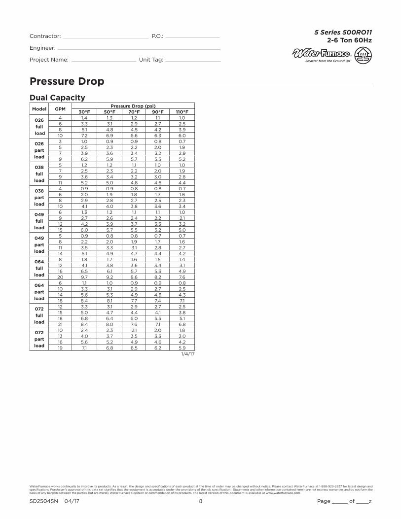
Pressure Drop
Dual CapacityModel GPM
Pressure Drop (psi)30°F 50°F 70°F 90°F 110°F
026
full
load
4 1.4 1.3 1.2 1.1 1.06 3.3 3.1 2.9 2.7 2.58 5.1 4.8 4.5 4.2 3.910 7.2 6.9 6.6 6.3 6.0
026
part
load
3 1.0 0.9 0.9 0.8 0.75 2.5 2.3 2.2 2.0 1.97 3.9 3.6 3.4 3.2 2.99 6.2 5.9 5.7 5.5 5.2
038
full
load
5 1.2 1.2 1.1 1.0 1.07 2.5 2.3 2.2 2.0 1.99 3.6 3.4 3.2 3.0 2.811 5.2 5.0 4.8 4.6 4.4
038
part
load
4 0.9 0.9 0.8 0.8 0.76 2.0 1.9 1.8 1.7 1.68 2.9 2.8 2.7 2.5 2.310 4.1 4.0 3.8 3.6 3.4
049
full
load
6 1.3 1.2 1.1 1.1 1.09 2.7 2.6 2.4 2.2 2.112 4.2 3.9 3.7 3.3 3.215 6.0 5.7 5.5 5.2 5.0
049
part
load
5 0.9 0.8 0.8 0.7 0.78 2.2 2.0 1.9 1.7 1.611 3.5 3.3 3.1 2.8 2.714 5.1 4.9 4.7 4.4 4.2
064
full
load
8 1.8 1.7 1.6 1.5 1.412 4.1 3.8 3.6 3.4 3.116 6.5 6.1 5.7 5.3 4.920 9.7 9.2 8.6 8.2 7.6
064
part
load
6 1.1 1.0 0.9 0.9 0.810 3.3 3.1 2.9 2.7 2.514 5.6 5.3 4.9 4.6 4.318 8.4 8.1 7.7 7.4 7.1
072
full
load
12 3.3 3.1 2.9 2.7 2.515 5.0 4.7 4.4 4.1 3.818 6.8 6.4 6.0 5.5 5.121 8.4 8.0 7.6 7.1 6.8
072
part
load
10 2.4 2.3 2.1 2.0 1.813 4.0 3.7 3.5 3.3 3.016 5.6 5.2 4.9 4.6 4.219 7.1 6.8 6.5 6.2 5.9
1/4/17

WaterFurnace works continually to improve its products. As a result, the design and specifi cations of each product at the time of order may be changed without notice. Please contact WaterFurnace at 1-888-929-2837 for latest design and specifi cations. Purchaser’s approval of this data set signifi es that the equipment is acceptable under the provisions of the job specifi cation. Statements and other information contained herein are not express warranties and do not form the basis of any bargain between the parties, but are merely WaterFurnace’s opinion or commendation of its products. The latest version of this document is available at www.waterfurnace.com.
Contractor: P.O.: Engineer:
Project Name: Unit Tag:
SD2504SN 04/17 9 Page _____ of ____z
5 Series 500RO112-6 Ton 60Hz
NDS026 - Performance Data
Multiple Flow Rates (for EWT) are shown in the table above. The lowest fl ow rate shown is used for geothermal open loop/well water systems with a minimum 50° F. The
second fl ow rate shown is the minimum geothermal closed loop fl ow rate. The third fl ow rate shown is optimum for geothermal closed loop and the suggested fl ow rate
for boiler tower applications.
NDS026 - Dual Capacity Low Speed
EWT °F
Flow gpm
WPD HEATING - EAT 70°F COOLING - EAT 80/67 °F
PSI FTAirflow
cfmHC
MBtuhPower
kWHE
MBtuhLAT °F
COPAirflow
cfmTC
MBtuhSC
MBtuhS/T
RatioPower
kWHR
MBtuhEER
20
3.0 1.0 2.3Operation not recommended
Operation not recommended5.0 2.6 5.9
7.0 4.0 9.2500 11.7 1.22 7.6 91.7 2.82700 11.9 1.17 7.9 85.7 2.98
30
3.0 1.0 2.3 Operation not recommended Operation not recommended
5.0 2.5 5.8500 12.5 1.12 8.7 93.2 3.28 500 17.2 10.2 0.60 0.63 19.3 27.4700 13.1 1.15 9.1 87.3 3.32 700 17.5 11.2 0.64 0.66 19.7 26.4
7.0 3.9 8.9500 13.7 1.23 9.5 95.4 3.26 500 17.3 10.2 0.59 0.61 19.4 28.3700 13.9 1.18 9.9 88.4 3.45 700 17.7 11.2 0.63 0.64 19.9 27.7
40
3.0 1.0 2.2 Operation not recommended Operation not recommended
5.0 2.4 5.6500 14.9 1.14 11.0 97.5 3.80 500 18.6 12.3 0.66 0.68 21.0 27.2700 15.4 1.17 11.4 90.3 3.86 700 19.0 13.5 0.71 0.72 21.4 26.4
7.0 3.7 8.7500 15.7 1.17 11.7 99.0 3.91 500 18.8 12.3 0.66 0.66 21.0 28.3700 16.2 1.20 12.1 91.4 3.97 700 19.2 13.5 0.70 0.70 21.6 27.6
50
3.0 0.9 2.1500 16.6 1.17 12.6 100.7 4.16 500 19.6 13.8 0.70 0.76 22.2 25.8700 17.1 1.18 13.1 92.6 4.23 700 20.2 15.2 0.75 0.78 22.8 26.0
5.0 2.3 5.4500 17.2 1.17 13.2 101.8 4.31 500 19.8 13.8 0.70 0.74 22.3 26.7700 17.7 1.18 13.6 93.4 4.38 700 20.4 15.3 0.75 0.76 22.9 26.9
7.0 3.6 8.4500 18.0 1.20 13.9 103.3 4.40 500 20.1 14.2 0.70 0.74 22.7 27.4700 18.5 1.21 14.4 94.5 4.48 700 20.7 15.7 0.76 0.75 23.3 27.6
60
3.0 0.9 2.1500 18.8 1.19 14.7 104.7 4.60 500 19.1 13.6 0.71 0.86 22.1 22.1700 19.2 1.20 15.1 95.4 4.68 700 19.6 15.1 0.77 0.88 22.6 22.3
5.0 2.3 5.3500 19.5 1.19 15.4 106.1 4.80 500 19.3 13.7 0.71 0.84 22.2 22.9700 20.0 1.20 15.9 96.4 4.88 700 19.8 15.2 0.76 0.86 22.7 23.1
7.0 3.5 8.1500 20.2 1.22 16.0 107.4 4.86 500 19.6 14.0 0.72 0.83 22.5 23.5700 20.7 1.23 16.5 97.3 4.94 700 20.2 15.6 0.77 0.85 23.1 23.7
70
3.0 0.9 2.0500 20.9 1.22 16.8 108.8 5.02 500 18.6 13.5 0.73 0.97 21.9 19.3700 21.3 1.22 17.2 98.2 5.12 700 19.1 14.9 0.78 0.98 22.5 19.4
5.0 2.2 5.1500 21.8 1.22 17.7 110.5 5.26 500 18.8 13.6 0.72 0.94 22.0 20.0700 22.2 1.22 18.1 99.4 5.37 700 19.3 15.0 0.78 0.96 22.6 20.1
7.0 3.4 7.9500 22.4 1.24 18.2 111.5 5.29 500 19.1 13.9 0.73 0.93 22.3 20.5700 22.8 1.24 18.6 100.2 5.39 700 19.6 15.4 0.79 0.95 22.8 20.6
80
3.0 0.8 1.9500 23.1 1.25 18.8 112.8 5.42 500 17.2 12.1 0.70 1.09 20.9 15.7700 23.4 1.24 19.2 101.0 5.53 700 17.6 13.4 0.76 1.11 21.4 15.9
5.0 2.1 4.9500 24.2 1.24 20.0 114.8 5.72 500 17.3 12.2 0.70 1.06 21.0 16.3700 24.5 1.23 20.3 102.4 5.83 700 17.8 13.5 0.76 1.08 21.5 16.4
7.0 3.3 7.6500 24.5 1.27 20.2 115.5 5.68 500 17.6 12.5 0.71 1.05 21.2 16.7700 24.8 1.26 20.5 102.8 5.79 700 18.1 13.8 0.76 1.08 21.8 16.8
90
3.0 0.8 1.9500 25.3 1.28 20.9 116.8 5.80 500 15.7 10.7 0.68 1.22 19.9 12.9700 25.5 1.26 21.2 103.7 5.92 700 16.2 11.8 0.73 1.24 20.4 13.0
5.0 2.0 4.7500 26.6 1.27 22.2 119.2 6.15 500 15.9 10.7 0.68 1.19 20.1 13.4700 26.7 1.25 22.5 105.4 6.28 700 16.3 11.9 0.73 1.21 20.5 13.5
7.0 3.2 7.3500 26.7 1.29 22.3 119.4 6.06 500 16.2 11.0 0.68 1.18 20.2 13.7700 26.8 1.27 22.5 105.4 6.18 700 16.6 12.2 0.73 1.20 20.7 13.8
100
3.0 0.8 1.8
Operation not recommended
Operation not recommended
5.0 2.0 4.6500 14.9 11.5 0.77 1.38 19.6 10.8700 15.3 12.7 0.83 1.41 20.1 10.9
7.0 3.1 7.1500 15.1 11.8 0.78 1.37 19.8 11.1700 15.6 13.1 0.84 1.40 20.3 11.1
110
3.0 0.7 1.7 Operation not recommended
5.0 1.9 4.4500 13.9 12.2 0.88 1.57 19.2 8.8700 14.3 13.6 0.95 1.60 19.7 8.9
7.0 2.9 6.8500 14.1 12.6 0.89 1.56 19.4 9.0700 14.5 13.9 0.96 1.59 19.9 9.1
120
3.0 0.7 1.7 Operation not recommended
5.0 1.8 4.2500 13.1 12.2 0.93 1.81 19.3 7.2700 13.3 13.2 0.99 1.86 19.7 7.2
7.0 2.8 6.5500 13.2 12.2 0.92 1.75 19.2 7.5700 13.5 13.2 0.98 1.81 19.7 7.5
1/4/17
WaterFurnace works continually to improve its products. As a result, the design and specifi cations of each product at the time of order may be changed without notice. Please contact WaterFurnace at 1-888-929-2837 for latest design and specifi cations. Purchaser’s approval of this data set signifi es that the equipment is acceptable under the provisions of the job specifi cation. Statements and other information contained herein are not express warranties and do not form the basis of any bargain between the parties, but are merely WaterFurnace’s opinion or commendation of its products. The latest version of this document is available at www.waterfurnace.com.
Contractor: P.O.: Engineer:
Project Name: Unit Tag:
SD2504SN 04/17 10 Page _____ of ____z
5 Series 500RO112-6 Ton 60Hz
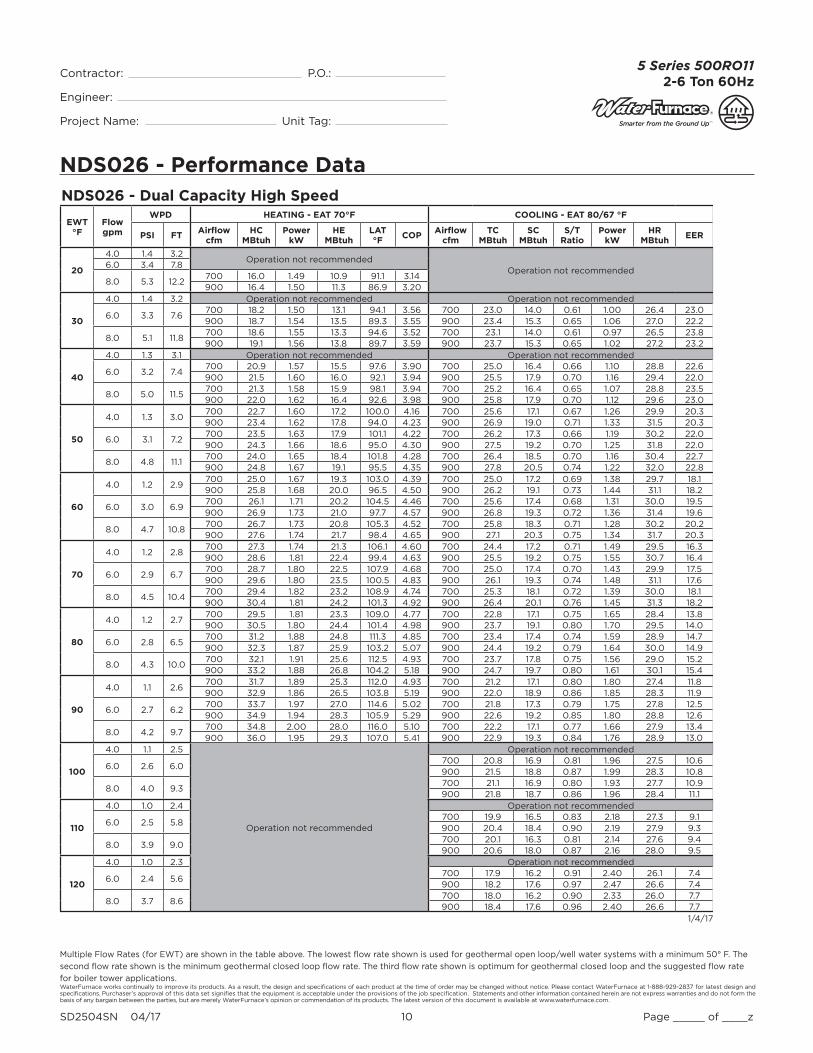
NDS026 - Performance Data
Multiple Flow Rates (for EWT) are shown in the table above. The lowest fl ow rate shown is used for geothermal open loop/well water systems with a minimum 50° F. The
second fl ow rate shown is the minimum geothermal closed loop fl ow rate. The third fl ow rate shown is optimum for geothermal closed loop and the suggested fl ow rate
for boiler tower applications.
NDS026 - Dual Capacity High Speed
EWT °F
Flow gpm
WPD HEATING - EAT 70°F COOLING - EAT 80/67 °F
PSI FTAirflow
cfmHC
MBtuhPower
kWHE
MBtuhLAT °F
COPAirflow
cfmTC
MBtuhSC
MBtuhS/T
RatioPower
kWHR
MBtuhEER
20
4.0 1.4 3.2Operation not recommended
Operation not recommended6.0 3.4 7.8
8.0 5.3 12.2700 16.0 1.49 10.9 91.1 3.14900 16.4 1.50 11.3 86.9 3.20
30
4.0 1.4 3.2 Operation not recommended Operation not recommended
6.0 3.3 7.6700 18.2 1.50 13.1 94.1 3.56 700 23.0 14.0 0.61 1.00 26.4 23.0900 18.7 1.54 13.5 89.3 3.55 900 23.4 15.3 0.65 1.06 27.0 22.2
8.0 5.1 11.8700 18.6 1.55 13.3 94.6 3.52 700 23.1 14.0 0.61 0.97 26.5 23.8900 19.1 1.56 13.8 89.7 3.59 900 23.7 15.3 0.65 1.02 27.2 23.2
40
4.0 1.3 3.1 Operation not recommended Operation not recommended
6.0 3.2 7.4700 20.9 1.57 15.5 97.6 3.90 700 25.0 16.4 0.66 1.10 28.8 22.6900 21.5 1.60 16.0 92.1 3.94 900 25.5 17.9 0.70 1.16 29.4 22.0
8.0 5.0 11.5700 21.3 1.58 15.9 98.1 3.94 700 25.2 16.4 0.65 1.07 28.8 23.5900 22.0 1.62 16.4 92.6 3.98 900 25.8 17.9 0.70 1.12 29.6 23.0
50
4.0 1.3 3.0700 22.7 1.60 17.2 100.0 4.16 700 25.6 17.1 0.67 1.26 29.9 20.3900 23.4 1.62 17.8 94.0 4.23 900 26.9 19.0 0.71 1.33 31.5 20.3
6.0 3.1 7.2700 23.5 1.63 17.9 101.1 4.22 700 26.2 17.3 0.66 1.19 30.2 22.0900 24.3 1.66 18.6 95.0 4.30 900 27.5 19.2 0.70 1.25 31.8 22.0
8.0 4.8 11.1700 24.0 1.65 18.4 101.8 4.28 700 26.4 18.5 0.70 1.16 30.4 22.7900 24.8 1.67 19.1 95.5 4.35 900 27.8 20.5 0.74 1.22 32.0 22.8
60
4.0 1.2 2.9700 25.0 1.67 19.3 103.0 4.39 700 25.0 17.2 0.69 1.38 29.7 18.1900 25.8 1.68 20.0 96.5 4.50 900 26.2 19.1 0.73 1.44 31.1 18.2
6.0 3.0 6.9700 26.1 1.71 20.2 104.5 4.46 700 25.6 17.4 0.68 1.31 30.0 19.5900 26.9 1.73 21.0 97.7 4.57 900 26.8 19.3 0.72 1.36 31.4 19.6
8.0 4.7 10.8700 26.7 1.73 20.8 105.3 4.52 700 25.8 18.3 0.71 1.28 30.2 20.2900 27.6 1.74 21.7 98.4 4.65 900 27.1 20.3 0.75 1.34 31.7 20.3
70
4.0 1.2 2.8700 27.3 1.74 21.3 106.1 4.60 700 24.4 17.2 0.71 1.49 29.5 16.3900 28.6 1.81 22.4 99.4 4.63 900 25.5 19.2 0.75 1.55 30.7 16.4
6.0 2.9 6.7700 28.7 1.80 22.5 107.9 4.68 700 25.0 17.4 0.70 1.43 29.9 17.5900 29.6 1.80 23.5 100.5 4.83 900 26.1 19.3 0.74 1.48 31.1 17.6
8.0 4.5 10.4700 29.4 1.82 23.2 108.9 4.74 700 25.3 18.1 0.72 1.39 30.0 18.1900 30.4 1.81 24.2 101.3 4.92 900 26.4 20.1 0.76 1.45 31.3 18.2
80
4.0 1.2 2.7700 29.5 1.81 23.3 109.0 4.77 700 22.8 17.1 0.75 1.65 28.4 13.8900 30.5 1.80 24.4 101.4 4.98 900 23.7 19.1 0.80 1.70 29.5 14.0
6.0 2.8 6.5700 31.2 1.88 24.8 111.3 4.85 700 23.4 17.4 0.74 1.59 28.9 14.7900 32.3 1.87 25.9 103.2 5.07 900 24.4 19.2 0.79 1.64 30.0 14.9
8.0 4.3 10.0700 32.1 1.91 25.6 112.5 4.93 700 23.7 17.8 0.75 1.56 29.0 15.2900 33.2 1.88 26.8 104.2 5.18 900 24.7 19.7 0.80 1.61 30.1 15.4
90
4.0 1.1 2.6700 31.7 1.89 25.3 112.0 4.93 700 21.2 17.1 0.80 1.80 27.4 11.8900 32.9 1.86 26.5 103.8 5.19 900 22.0 18.9 0.86 1.85 28.3 11.9
6.0 2.7 6.2700 33.7 1.97 27.0 114.6 5.02 700 21.8 17.3 0.79 1.75 27.8 12.5900 34.9 1.94 28.3 105.9 5.29 900 22.6 19.2 0.85 1.80 28.8 12.6
8.0 4.2 9.7700 34.8 2.00 28.0 116.0 5.10 700 22.2 17.1 0.77 1.66 27.9 13.4900 36.0 1.95 29.3 107.0 5.41 900 22.9 19.3 0.84 1.76 28.9 13.0
100
4.0 1.1 2.5
Operation not recommended
Operation not recommended
6.0 2.6 6.0700 20.8 16.9 0.81 1.96 27.5 10.6900 21.5 18.8 0.87 1.99 28.3 10.8
8.0 4.0 9.3700 21.1 16.9 0.80 1.93 27.7 10.9900 21.8 18.7 0.86 1.96 28.4 11.1
110
4.0 1.0 2.4 Operation not recommended
6.0 2.5 5.8700 19.9 16.5 0.83 2.18 27.3 9.1900 20.4 18.4 0.90 2.19 27.9 9.3
8.0 3.9 9.0700 20.1 16.3 0.81 2.14 27.6 9.4900 20.6 18.0 0.87 2.16 28.0 9.5
120
4.0 1.0 2.3 Operation not recommended
6.0 2.4 5.6700 17.9 16.2 0.91 2.40 26.1 7.4900 18.2 17.6 0.97 2.47 26.6 7.4
8.0 3.7 8.6700 18.0 16.2 0.90 2.33 26.0 7.7900 18.4 17.6 0.96 2.40 26.6 7.7
1/4/17

WaterFurnace works continually to improve its products. As a result, the design and specifi cations of each product at the time of order may be changed without notice. Please contact WaterFurnace at 1-888-929-2837 for latest design and specifi cations. Purchaser’s approval of this data set signifi es that the equipment is acceptable under the provisions of the job specifi cation. Statements and other information contained herein are not express warranties and do not form the basis of any bargain between the parties, but are merely WaterFurnace’s opinion or commendation of its products. The latest version of this document is available at www.waterfurnace.com.
Contractor: P.O.: Engineer:
Project Name: Unit Tag:
SD2504SN 04/17 11 Page _____ of ____z
5 Series 500RO112-6 Ton 60Hz
NDS038 - Performance Data
Multiple Flow Rates (for EWT) are shown in the table above. The lowest fl ow rate shown is used for geothermal open loop/well water systems with a minimum 50° F. The
second fl ow rate shown is the minimum geothermal closed loop fl ow rate. The third fl ow rate shown is optimum for geothermal closed loop and the suggested fl ow rate
for boiler tower applications.
NDS038 - Dual Capacity Low Speed
EWT °F
Flow gpm
WPD HEATING - EAT 70°F COOLING - EAT 80/67 °F
PSI FTAirflow
cfmHC
MBtuhPower
kWHE
MBtuhLAT °F
COPAirflow
cfmTC
MBtuhSC
MBtuhS/T
RatioPower
kWHR
MBtuhEER
20
4.0 1.0 2.2Operation not recommended
Operation not recommended6.0 2.1 4.9
8.0 3.1 7.2800 17.2 1.69 11.4 89.9 2.971000 17.5 1.70 11.7 86.2 3.02
30
4.0 0.9 2.2 Operation not recommended Operation not recommended
6.0 2.0 4.7800 18.3 1.65 12.7 91.2 3.25 800 23.4 13.6 0.58 0.84 26.3 27.71000 19.1 1.70 13.3 87.7 3.29 1000 23.8 14.9 0.63 0.89 26.8 26.7
8.0 3.0 7.0800 19.9 1.73 14.0 93.0 3.37 800 23.5 13.6 0.58 0.82 26.6 28.71000 20.3 1.74 14.4 88.8 3.42 1000 24.1 14.9 0.62 0.86 27.0 28.0
40
4.0 0.9 2.1 Operation not recommended Operation not recommended
6.0 2.0 4.6800 21.6 1.68 15.9 95.1 3.77 800 26.2 16.9 0.65 0.93 29.4 28.31000 22.4 1.71 16.6 90.7 3.83 1000 26.7 18.5 0.69 0.97 30.0 27.5
8.0 2.9 6.7800 22.8 1.72 16.9 96.4 3.88 800 26.4 16.9 0.64 0.90 29.5 29.41000 23.6 1.76 17.6 91.9 3.94 1000 27.0 18.5 0.69 0.94 30.2 28.7
50
4.0 0.9 2.0800 24.1 1.71 18.3 97.9 4.14 800 28.4 19.4 0.68 1.04 31.9 27.41000 24.9 1.73 19.0 93.0 4.21 1000 29.2 21.4 0.73 1.06 32.8 27.6
6.0 1.9 4.4800 25.0 1.71 19.1 98.9 4.28 800 28.6 19.5 0.68 1.01 32.1 28.41000 25.7 1.73 19.8 93.8 4.35 1000 29.4 21.5 0.73 1.03 32.9 28.6
8.0 2.8 6.5800 26.1 1.75 20.2 100.2 4.38 800 29.1 20.0 0.69 1.00 32.5 29.11000 26.9 1.77 20.9 94.9 4.45 1000 29.9 22.1 0.74 1.02 33.4 29.3
60
4.0 0.9 2.0800 27.3 1.75 21.3 101.6 4.56 800 27.9 19.6 0.70 1.18 31.9 23.61000 28.0 1.77 21.9 95.9 4.64 1000 28.7 21.7 0.76 1.21 32.8 23.8
6.0 1.9 4.3800 28.4 1.75 22.4 102.9 4.75 800 28.1 19.7 0.70 1.15 32.1 24.41000 29.1 1.76 23.1 96.9 4.83 1000 28.9 21.8 0.75 1.18 32.9 24.6
8.0 2.7 6.3800 29.4 1.79 23.3 104.0 4.81 800 28.6 20.2 0.71 1.14 32.5 25.01000 30.1 1.80 23.9 97.8 4.89 1000 29.4 22.4 0.76 1.17 33.4 25.2
70
4.0 0.8 1.9800 30.5 1.80 24.3 105.3 4.96 800 27.4 19.8 0.72 1.33 32.0 20.61000 31.1 1.81 24.9 98.8 5.04 1000 28.2 21.9 0.78 1.36 32.8 20.8
6.0 1.8 4.2800 31.8 1.79 25.7 106.8 5.19 800 27.7 19.9 0.72 1.30 32.1 21.31000 32.4 1.79 26.3 100.0 5.29 1000 28.4 22.0 0.78 1.32 32.9 21.5
8.0 2.7 6.1800 32.6 1.83 26.4 107.8 5.22 800 28.1 20.4 0.73 1.29 32.5 21.91000 33.2 1.83 27.0 100.7 5.32 1000 28.9 22.6 0.78 1.31 33.4 22.1
80
4.0 0.8 1.9800 33.3 1.83 27.1 108.6 5.34 800 25.6 19.4 0.76 1.53 30.8 16.81000 33.8 1.82 27.6 101.3 5.44 1000 26.3 21.5 0.82 1.56 31.6 16.9
6.0 1.7 4.0800 34.9 1.82 28.7 110.4 5.63 800 25.8 19.5 0.76 1.49 30.9 17.41000 35.4 1.81 29.2 102.7 5.74 1000 26.6 21.6 0.81 1.52 31.7 17.5
8.0 2.6 5.9800 35.4 1.86 29.1 111.0 5.59 800 26.3 20.0 0.76 1.48 31.3 17.81000 35.8 1.84 29.5 103.1 5.70 1000 27.0 22.2 0.82 1.51 32.1 17.9
90
4.0 0.8 1.8800 36.2 1.86 29.9 111.9 5.71 800 23.8 19.0 0.80 1.73 29.7 13.81000 36.5 1.84 30.2 103.8 5.82 1000 24.5 21.0 0.86 1.76 30.5 13.9
6.0 1.7 3.9800 38.1 1.84 31.8 114.1 6.05 800 24.0 19.1 0.80 1.68 29.8 14.31000 38.3 1.82 32.1 105.5 6.18 1000 24.7 21.2 0.86 1.72 30.5 14.4
8.0 2.5 5.7800 38.2 1.88 32.0 114.2 5.96 800 24.2 19.3 0.80 1.65 30.0 14.71000 38.4 1.85 32.1 105.6 6.08 1000 25.1 21.7 0.86 1.70 30.9 14.8
100
4.0 0.7 1.7
Operation not recommended
Operation not recommended
6.0 1.6 3.7800 22.5 18.5 0.82 1.93 29.1 11.71000 23.2 20.5 0.89 1.96 29.9 11.8
8.0 2.4 5.5800 22.9 19.0 0.83 1.91 29.4 12.01000 23.6 21.1 0.89 1.95 30.2 12.1
110
4.0 0.7 1.7 Operation not recommended
6.0 1.6 3.6800 21.1 18.0 0.85 2.17 28.5 9.71000 21.6 19.9 0.92 2.21 29.2 9.8
8.0 2.3 5.3800 21.4 18.4 0.86 2.15 28.7 10.01000 22.0 20.4 0.93 2.19 29.5 10.0
120
4.0 0.7 1.6 Operation not recommended
6.0 1.5 3.5800 18.8 16.2 0.86 2.49 27.3 7.51000 19.2 17.6 0.92 2.56 27.9 7.5
8.0 2.2 5.1800 19.0 16.2 0.85 2.41 27.2 7.91000 19.4 17.6 0.91 2.49 27.9 7.8
1/4/17

WaterFurnace works continually to improve its products. As a result, the design and specifi cations of each product at the time of order may be changed without notice. Please contact WaterFurnace at 1-888-929-2837 for latest design and specifi cations. Purchaser’s approval of this data set signifi es that the equipment is acceptable under the provisions of the job specifi cation. Statements and other information contained herein are not express warranties and do not form the basis of any bargain between the parties, but are merely WaterFurnace’s opinion or commendation of its products. The latest version of this document is available at www.waterfurnace.com.
Contractor: P.O.: Engineer:
Project Name: Unit Tag:
SD2504SN 04/17 12 Page _____ of ____z
5 Series 500RO112-6 Ton 60Hz
NDS038 - Performance Data
Multiple Flow Rates (for EWT) are shown in the table above. The lowest fl ow rate shown is used for geothermal open loop/well water systems with a minimum 50° F. The
second fl ow rate shown is the minimum geothermal closed loop fl ow rate. The third fl ow rate shown is optimum for geothermal closed loop and the suggested fl ow rate
for boiler tower applications.
NDS038 - Dual Capacity High Speed
EWT °F
Flow gpm
WPD HEATING - EAT 70°F COOLING - EAT 80/67 °F
PSI FTAirflow
cfmHC
MBtuhPower
kWHE
MBtuhLAT °F
COPAirflow
cfmTC
MBtuhSC
MBtuhS/T
RatioPower
kWHR
MBtuhEER
20
5.0 1.3 3.0Operation not recommended
Operation not recommended7.0 2.6 5.9
9.0 3.7 8.71000 24.3 2.22 16.7 92.5 3.211200 24.9 2.24 17.3 89.2 3.26
30
5.0 1.2 2.9 Operation not recommended Operation not recommended
7.0 2.5 5.81000 28.2 2.29 20.4 96.1 3.62 1000 30.4 18.5 0.61 1.41 35.2 21.51200 29.0 2.36 21.0 92.4 3.61 1200 30.9 20.2 0.65 1.49 36.0 20.7
9.0 3.6 8.41000 28.9 2.36 20.8 96.8 3.59 1000 30.6 18.5 0.61 1.37 35.4 22.31200 29.6 2.38 21.5 92.8 3.65 1200 31.3 20.2 0.65 1.44 36.2 21.7
40
5.0 1.2 2.8 Operation not recommended Operation not recommended
7.0 2.4 5.61000 31.9 2.39 23.8 99.6 3.91 1000 33.6 20.5 0.61 1.56 38.9 21.61200 32.9 2.44 24.6 95.4 3.95 1200 34.2 22.4 0.65 1.63 39.8 21.0
9.0 3.5 8.21000 32.6 2.41 24.3 100.2 3.95 1000 33.8 20.5 0.61 1.51 39.0 22.41200 33.6 2.47 25.2 95.9 3.99 1200 34.6 22.4 0.65 1.58 40.0 21.9
50
5.0 1.2 2.71000 34.4 2.44 26.1 101.9 4.14 1000 34.9 20.5 0.59 1.78 41.0 19.61200 35.4 2.47 27.0 97.3 4.20 1200 36.7 22.8 0.62 1.87 43.1 19.6
7.0 2.3 5.41000 35.7 2.49 27.1 103.0 4.19 1000 35.7 20.7 0.58 1.68 41.4 21.21200 36.8 2.53 28.2 98.4 4.27 1200 37.5 23.0 0.61 1.76 43.5 21.3
9.0 3.4 7.91000 36.5 2.52 27.9 103.8 4.25 1000 36.0 22.1 0.62 1.64 41.6 22.01200 37.6 2.55 28.9 99.0 4.32 1200 37.9 24.6 0.65 1.72 43.8 22.0
60
5.0 1.1 2.61000 37.2 2.53 28.6 104.5 4.32 1000 35.5 22.7 0.64 1.96 42.2 18.11200 38.4 2.54 29.7 99.6 4.43 1200 37.2 25.2 0.68 2.04 44.2 18.2
7.0 2.3 5.31000 38.9 2.60 30.0 106.0 4.39 1000 36.3 22.9 0.63 1.86 42.7 19.51200 40.2 2.61 31.2 101.0 4.50 1200 38.1 25.4 0.67 1.94 44.7 19.7
9.0 3.3 7.61000 39.8 2.62 30.9 106.9 4.45 1000 36.7 24.2 0.66 1.81 42.9 20.21200 41.2 2.64 32.2 101.8 4.58 1200 38.5 26.8 0.70 1.90 45.0 20.3
70
5.0 1.1 2.51000 40.1 2.61 31.2 107.1 4.50 1000 36.1 24.9 0.69 2.13 43.4 16.91200 42.7 2.67 33.6 102.9 4.69 1200 37.7 27.7 0.73 2.21 45.2 17.0
7.0 2.2 5.11000 42.1 2.70 32.9 109.0 4.58 1000 37.0 25.2 0.68 2.04 44.0 18.21200 43.5 2.70 34.3 103.6 4.73 1200 38.6 27.9 0.72 2.11 45.8 18.3
9.0 3.2 7.41000 43.2 2.73 33.9 110.0 4.64 1000 37.4 26.2 0.70 1.99 44.2 18.81200 44.7 2.72 35.4 104.5 4.82 1200 39.1 29.0 0.74 2.07 46.2 18.9
80
5.0 1.1 2.51000 43.3 2.73 34.0 110.1 4.65 1000 34.8 24.6 0.71 2.34 42.8 14.81200 44.8 2.71 35.6 104.6 4.85 1200 36.2 27.3 0.76 2.41 44.4 15.0
7.0 2.1 4.91000 45.8 2.84 36.1 112.4 4.73 1000 35.7 24.9 0.70 2.26 43.4 15.81200 47.3 2.81 37.7 106.5 4.94 1200 37.2 27.6 0.74 2.33 45.1 16.0
9.0 3.1 7.11000 47.1 2.87 37.3 113.6 4.80 1000 36.1 25.5 0.71 2.21 43.7 16.31200 48.7 2.83 39.0 107.6 5.04 1200 37.6 28.3 0.75 2.28 45.4 16.5
90
5.0 1.0 2.41000 46.5 2.84 36.8 113.0 4.79 1000 33.4 24.3 0.73 2.55 42.1 13.11200 48.1 2.80 38.6 107.1 5.04 1200 34.6 27.0 0.78 2.62 43.5 13.2
7.0 2.0 4.71000 49.4 2.97 39.2 115.7 4.87 1000 34.4 24.6 0.71 2.48 42.9 13.91200 51.1 2.92 41.2 109.5 5.14 1200 35.7 27.3 0.76 2.54 44.4 14.0
9.0 3.0 6.91000 50.9 3.01 40.7 117.2 4.95 1000 35.2 25.2 0.72 2.37 43.3 14.91200 52.7 2.94 42.7 110.7 5.25 1200 36.1 27.5 0.76 2.49 44.6 14.5
100
5.0 1.0 2.3
Operation not recommended
Operation not recommended
7.0 2.0 4.61000 31.6 24.0 0.76 2.77 41.0 11.41200 32.6 26.7 0.82 2.81 42.2 11.6
9.0 2.9 6.61000 31.9 24.0 0.75 2.72 41.2 11.71200 33.0 26.5 0.80 2.76 42.4 11.9
110
5.0 1.0 2.2 Operation not recommended
7.0 1.9 4.41000 28.7 23.4 0.82 3.05 39.1 9.41200 29.5 26.0 0.88 3.07 40.0 9.6
9.0 2.8 6.41000 29.0 23.1 0.80 3.00 39.2 9.71200 29.8 25.5 0.86 3.03 40.1 9.8
120
5.0 0.9 2.1 Operation not recommended
7.0 1.8 4.21000 26.9 22.8 0.85 3.38 38.4 8.01200 27.4 24.7 0.90 3.46 39.2 7.9
9.0 2.7 6.11000 27.1 22.8 0.84 3.27 38.3 8.31200 27.7 24.7 0.89 3.37 39.2 8.2
1/4/17

WaterFurnace works continually to improve its products. As a result, the design and specifi cations of each product at the time of order may be changed without notice. Please contact WaterFurnace at 1-888-929-2837 for latest design and specifi cations. Purchaser’s approval of this data set signifi es that the equipment is acceptable under the provisions of the job specifi cation. Statements and other information contained herein are not express warranties and do not form the basis of any bargain between the parties, but are merely WaterFurnace’s opinion or commendation of its products. The latest version of this document is available at www.waterfurnace.com.
Contractor: P.O.: Engineer:
Project Name: Unit Tag:
SD2504SN 04/17 13 Page _____ of ____z
5 Series 500RO112-6 Ton 60Hz
NDS049 - Performance Data
Multiple Flow Rates (for EWT) are shown in the table above. The lowest fl ow rate shown is used for geothermal open loop/well water systems with a minimum 50° F. The
second fl ow rate shown is the minimum geothermal closed loop fl ow rate. The third fl ow rate shown is optimum for geothermal closed loop and the suggested fl ow rate
for boiler tower applications.
NDS049 - Dual Capacity Low Speed
EWT °F
Flow gpm
WPD HEATING - EAT 70°F COOLING - EAT 80/67 °F
PSI FTAirflow
cfmHC
MBtuhPower
kWHE
MBtuhLAT °F
COPAirflow
cfmTC
MBtuhSC
MBtuhS/T
RatioPower
kWHR
MBtuhEER
20
5.0 0.9 2.1Operation not recommended
Operation not recommended8.0 2.2 5.1
11.0 3.6 8.41200 21.1 2.25 13.4 86.3 2.751400 21.6 2.28 13.8 84.3 2.78
30
5.0 0.9 2.1 Operation not recommended Operation not recommended
8.0 2.2 5.01200 25.1 2.28 17.3 89.3 3.22 1200 34.3 22.1 0.64 1.22 38.4 28.21400 25.8 2.30 18.0 87.1 3.29 1400 34.8 24.1 0.69 1.28 39.2 27.2
11.0 3.5 8.21200 26.0 2.30 18.2 90.1 3.31 1200 34.5 22.1 0.64 1.18 38.5 29.21400 26.6 2.33 18.7 87.6 3.35 1400 35.3 24.1 0.68 1.24 39.5 28.5
40
5.0 0.9 2.0 Operation not recommended Operation not recommended
8.0 2.1 4.81200 30.9 2.34 22.9 93.8 3.86 1200 37.4 25.5 0.68 1.35 42.0 27.81400 32.0 2.34 24.0 91.2 4.00 1400 38.1 27.8 0.73 1.41 42.9 27.0
11.0 3.4 7.91200 31.9 2.36 23.9 94.6 3.96 1200 37.7 25.5 0.68 1.31 42.1 28.91400 33.0 2.38 24.9 91.8 4.07 1400 38.5 27.8 0.72 1.37 43.2 28.2
50
5.0 0.8 2.01200 34.1 2.33 26.1 96.3 4.29 1200 39.4 26.6 0.68 1.74 45.3 22.71400 35.2 2.33 27.2 93.3 4.43 1400 40.6 31.4 0.77 1.81 46.8 22.4
8.0 2.0 4.71200 36.7 2.40 28.5 98.4 4.48 1200 40.2 26.7 0.66 1.50 45.4 26.71400 38.1 2.39 30.0 95.2 4.68 1400 41.5 31.5 0.76 1.58 46.8 26.3
11.0 3.3 7.71200 38.1 2.42 29.9 99.4 4.62 1200 40.5 26.7 0.66 1.42 45.6 28.61400 39.4 2.42 31.1 96.1 4.77 1400 41.7 31.5 0.76 1.49 46.8 28.0
60
5.0 0.8 1.91200 36.3 2.40 28.1 98.0 4.43 1200 37.0 26.2 0.71 1.91 43.5 19.31400 37.6 2.38 29.4 94.8 4.62 1400 38.2 30.9 0.81 2.00 45.0 19.1
8.0 2.0 4.51200 39.2 2.46 30.8 100.3 4.68 1200 37.6 26.4 0.70 1.70 43.4 22.11400 40.8 2.43 32.5 97.0 4.92 1400 38.8 31.1 0.80 1.78 44.8 21.8
11.0 3.2 7.41200 40.9 2.48 32.4 101.6 4.83 1200 38.0 26.5 0.70 1.61 43.5 23.61400 42.4 2.45 34.0 98.0 5.07 1400 39.2 31.2 0.79 1.69 44.9 23.3
70
5.0 0.8 1.81200 38.5 2.47 30.1 99.7 4.57 1200 34.6 25.8 0.75 2.09 41.8 16.61400 42.0 2.46 33.6 97.8 5.00 1400 35.7 30.4 0.85 2.19 43.2 16.3
8.0 1.9 4.41200 41.8 2.51 33.2 102.2 4.88 1200 35.0 26.1 0.75 1.89 42.0 18.51400 43.4 2.47 35.0 98.7 5.16 1400 36.1 30.7 0.85 1.98 42.8 18.2
11.0 3.1 7.21200 43.7 2.54 35.0 103.7 5.04 1200 35.6 26.2 0.74 1.81 42.3 19.71400 45.3 2.48 36.8 100.0 5.35 1400 36.7 30.8 0.84 1.88 43.1 19.5
80
5.0 0.8 1.81200 41.3 2.50 32.7 101.9 4.83 1200 32.4 24.7 0.76 2.33 40.4 13.91400 42.9 2.46 34.5 98.4 5.11 1400 33.4 29.1 0.87 2.43 41.7 13.8
8.0 1.8 4.21200 44.8 2.53 36.2 104.6 5.19 1200 32.6 25.0 0.77 2.16 40.0 15.11400 46.7 2.47 38.2 100.9 5.54 1400 33.6 29.4 0.88 2.25 41.2 14.9
11.0 3.0 6.91200 47.1 2.56 38.4 106.4 5.39 1200 33.3 25.2 0.76 2.07 40.4 16.11400 49.0 2.49 40.5 102.4 5.77 1400 34.4 29.6 0.86 2.16 41.7 15.9
90
5.0 0.7 1.71200 44.1 2.54 35.4 104.0 5.08 1200 30.2 23.6 0.78 2.56 38.3 11.81400 45.8 2.49 37.3 100.3 5.40 1400 31.2 27.7 0.89 2.67 40.3 11.7
8.0 1.8 4.11200 47.9 2.56 39.2 107.0 5.50 1200 30.2 23.9 0.79 2.43 38.5 12.41400 49.9 2.47 41.5 103.0 5.92 1400 31.0 28.1 0.91 2.52 39.6 12.3
11.0 2.9 6.71200 50.6 2.58 41.8 109.0 5.74 1200 31.5 26.3 0.83 2.35 39.5 13.41400 52.7 2.50 44.2 104.9 6.18 1400 32.0 28.4 0.89 2.43 40.3 13.2
100
5.0 0.7 1.6
Operation not recommended
Operation not recommended
8.0 1.7 3.91200 27.5 22.4 0.81 2.73 36.9 10.11400 28.4 26.4 0.93 2.84 38.1 10.0
11.0 2.8 6.51200 28.6 22.7 0.80 2.64 37.6 10.81400 29.4 26.7 0.91 2.75 38.8 10.7
110
5.0 0.7 1.6 Operation not recommended
8.0 1.6 3.81200 24.9 20.9 0.84 3.04 35.3 8.21400 25.7 24.6 0.96 3.16 36.5 8.1
11.0 2.7 6.21200 26.1 21.3 0.82 2.94 36.1 8.91400 26.8 25.0 0.93 3.07 37.3 8.7
120
5.0 0.7 1.5 Operation not recommended
8.0 1.6 3.61200 23.9 21.4 0.90 3.45 35.6 6.91400 24.3 23.2 0.95 3.54 36.4 6.9
11.0 2.6 6.01200 24.1 21.4 0.89 3.34 35.5 7.21400 24.6 23.2 0.94 3.44 36.3 7.2
1/4/17
WaterFurnace works continually to improve its products. As a result, the design and specifi cations of each product at the time of order may be changed without notice. Please contact WaterFurnace at 1-888-929-2837 for latest design and specifi cations. Purchaser’s approval of this data set signifi es that the equipment is acceptable under the provisions of the job specifi cation. Statements and other information contained herein are not express warranties and do not form the basis of any bargain between the parties, but are merely WaterFurnace’s opinion or commendation of its products. The latest version of this document is available at www.waterfurnace.com.
Contractor: P.O.: Engineer:
Project Name: Unit Tag:
SD2504SN 04/17 14 Page _____ of ____z
5 Series 500RO112-6 Ton 60Hz
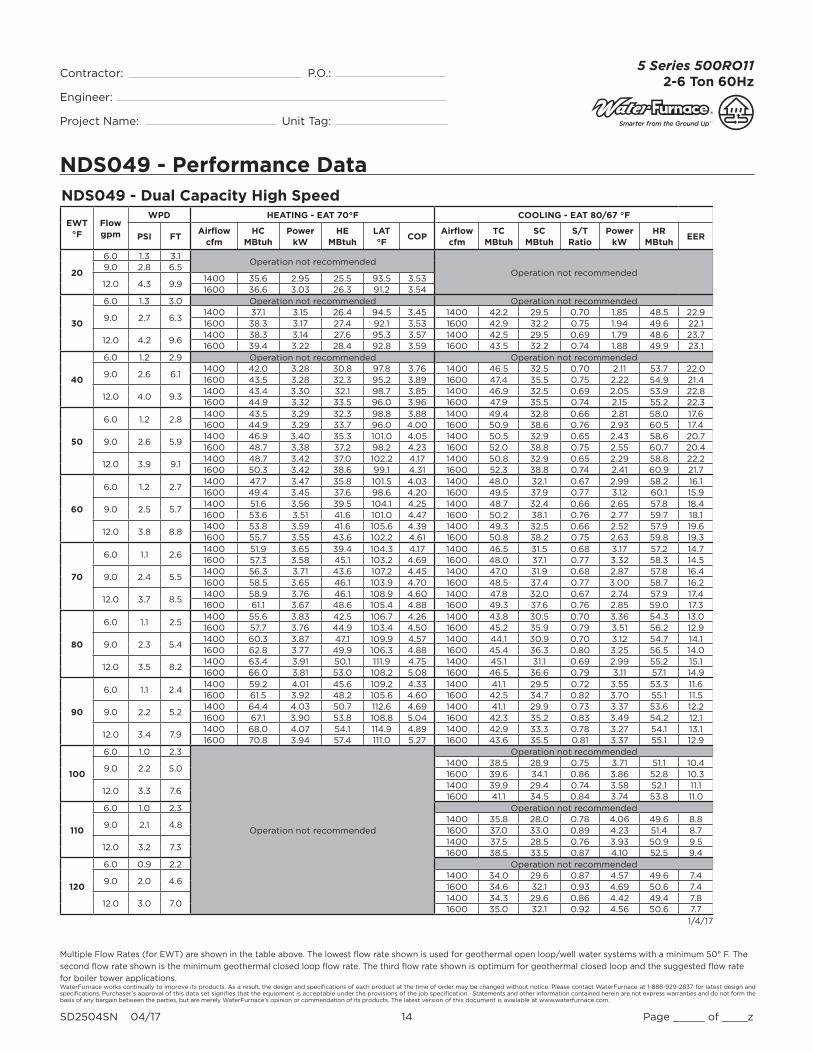
NDS049 - Performance Data
Multiple Flow Rates (for EWT) are shown in the table above. The lowest fl ow rate shown is used for geothermal open loop/well water systems with a minimum 50° F. The
second fl ow rate shown is the minimum geothermal closed loop fl ow rate. The third fl ow rate shown is optimum for geothermal closed loop and the suggested fl ow rate
for boiler tower applications.
NDS049 - Dual Capacity High Speed
EWT °F
Flow gpm
WPD HEATING - EAT 70°F COOLING - EAT 80/67 °F
PSI FTAirflow
cfmHC
MBtuhPower
kWHE
MBtuhLAT °F
COPAirflow
cfmTC
MBtuhSC
MBtuhS/T
RatioPower
kWHR
MBtuhEER
20
6.0 1.3 3.1Operation not recommended
Operation not recommended9.0 2.8 6.5
12.0 4.3 9.91400 35.6 2.95 25.5 93.5 3.531600 36.6 3.03 26.3 91.2 3.54
30
6.0 1.3 3.0 Operation not recommended Operation not recommended
9.0 2.7 6.31400 37.1 3.15 26.4 94.5 3.45 1400 42.2 29.5 0.70 1.85 48.5 22.91600 38.3 3.17 27.4 92.1 3.53 1600 42.9 32.2 0.75 1.94 49.6 22.1
12.0 4.2 9.61400 38.3 3.14 27.6 95.3 3.57 1400 42.5 29.5 0.69 1.79 48.6 23.71600 39.4 3.22 28.4 92.8 3.59 1600 43.5 32.2 0.74 1.88 49.9 23.1
40
6.0 1.2 2.9 Operation not recommended Operation not recommended
9.0 2.6 6.11400 42.0 3.28 30.8 97.8 3.76 1400 46.5 32.5 0.70 2.11 53.7 22.01600 43.5 3.28 32.3 95.2 3.89 1600 47.4 35.5 0.75 2.22 54.9 21.4
12.0 4.0 9.31400 43.4 3.30 32.1 98.7 3.85 1400 46.9 32.5 0.69 2.05 53.9 22.81600 44.9 3.32 33.5 96.0 3.96 1600 47.9 35.5 0.74 2.15 55.2 22.3
50
6.0 1.2 2.81400 43.5 3.29 32.3 98.8 3.88 1400 49.4 32.8 0.66 2.81 58.0 17.61600 44.9 3.29 33.7 96.0 4.00 1600 50.9 38.6 0.76 2.93 60.5 17.4
9.0 2.6 5.91400 46.9 3.40 35.3 101.0 4.05 1400 50.5 32.9 0.65 2.43 58.6 20.71600 48.7 3.38 37.2 98.2 4.23 1600 52.0 38.8 0.75 2.55 60.7 20.4
12.0 3.9 9.11400 48.7 3.42 37.0 102.2 4.17 1400 50.8 32.9 0.65 2.29 58.8 22.21600 50.3 3.42 38.6 99.1 4.31 1600 52.3 38.8 0.74 2.41 60.9 21.7
60
6.0 1.2 2.71400 47.7 3.47 35.8 101.5 4.03 1400 48.0 32.1 0.67 2.99 58.2 16.11600 49.4 3.45 37.6 98.6 4.20 1600 49.5 37.9 0.77 3.12 60.1 15.9
9.0 2.5 5.71400 51.6 3.56 39.5 104.1 4.25 1400 48.7 32.4 0.66 2.65 57.8 18.41600 53.6 3.51 41.6 101.0 4.47 1600 50.2 38.1 0.76 2.77 59.7 18.1
12.0 3.8 8.81400 53.8 3.59 41.6 105.6 4.39 1400 49.3 32.5 0.66 2.52 57.9 19.61600 55.7 3.55 43.6 102.2 4.61 1600 50.8 38.2 0.75 2.63 59.8 19.3
70
6.0 1.1 2.61400 51.9 3.65 39.4 104.3 4.17 1400 46.5 31.5 0.68 3.17 57.2 14.71600 57.3 3.58 45.1 103.2 4.69 1600 48.0 37.1 0.77 3.32 58.3 14.5
9.0 2.4 5.51400 56.3 3.71 43.6 107.2 4.45 1400 47.0 31.9 0.68 2.87 57.8 16.41600 58.5 3.65 46.1 103.9 4.70 1600 48.5 37.4 0.77 3.00 58.7 16.2
12.0 3.7 8.51400 58.9 3.76 46.1 108.9 4.60 1400 47.8 32.0 0.67 2.74 57.9 17.41600 61.1 3.67 48.6 105.4 4.88 1600 49.3 37.6 0.76 2.85 59.0 17.3
80
6.0 1.1 2.51400 55.6 3.83 42.5 106.7 4.26 1400 43.8 30.5 0.70 3.36 54.3 13.01600 57.7 3.76 44.9 103.4 4.50 1600 45.2 35.9 0.79 3.51 56.2 12.9
9.0 2.3 5.41400 60.3 3.87 47.1 109.9 4.57 1400 44.1 30.9 0.70 3.12 54.7 14.11600 62.8 3.77 49.9 106.3 4.88 1600 45.4 36.3 0.80 3.25 56.5 14.0
12.0 3.5 8.21400 63.4 3.91 50.1 111.9 4.75 1400 45.1 31.1 0.69 2.99 55.2 15.11600 66.0 3.81 53.0 108.2 5.08 1600 46.5 36.6 0.79 3.11 57.1 14.9
90
6.0 1.1 2.41400 59.2 4.01 45.6 109.2 4.33 1400 41.1 29.5 0.72 3.55 53.3 11.61600 61.5 3.92 48.2 105.6 4.60 1600 42.5 34.7 0.82 3.70 55.1 11.5
9.0 2.2 5.21400 64.4 4.03 50.7 112.6 4.69 1400 41.1 29.9 0.73 3.37 53.6 12.21600 67.1 3.90 53.8 108.8 5.04 1600 42.3 35.2 0.83 3.49 54.2 12.1
12.0 3.4 7.91400 68.0 4.07 54.1 114.9 4.89 1400 42.9 33.3 0.78 3.27 54.1 13.11600 70.8 3.94 57.4 111.0 5.27 1600 43.6 35.5 0.81 3.37 55.1 12.9
100
6.0 1.0 2.3
Operation not recommended
Operation not recommended
9.0 2.2 5.01400 38.5 28.9 0.75 3.71 51.1 10.41600 39.6 34.1 0.86 3.86 52.8 10.3
12.0 3.3 7.61400 39.9 29.4 0.74 3.58 52.1 11.11600 41.1 34.5 0.84 3.74 53.8 11.0
110
6.0 1.0 2.3 Operation not recommended
9.0 2.1 4.81400 35.8 28.0 0.78 4.06 49.6 8.81600 37.0 33.0 0.89 4.23 51.4 8.7
12.0 3.2 7.31400 37.5 28.5 0.76 3.93 50.9 9.51600 38.5 33.5 0.87 4.10 52.5 9.4
120
6.0 0.9 2.2 Operation not recommended
9.0 2.0 4.61400 34.0 29.6 0.87 4.57 49.6 7.41600 34.6 32.1 0.93 4.69 50.6 7.4
12.0 3.0 7.01400 34.3 29.6 0.86 4.42 49.4 7.81600 35.0 32.1 0.92 4.56 50.6 7.7
1/4/17

WaterFurnace works continually to improve its products. As a result, the design and specifi cations of each product at the time of order may be changed without notice. Please contact WaterFurnace at 1-888-929-2837 for latest design and specifi cations. Purchaser’s approval of this data set signifi es that the equipment is acceptable under the provisions of the job specifi cation. Statements and other information contained herein are not express warranties and do not form the basis of any bargain between the parties, but are merely WaterFurnace’s opinion or commendation of its products. The latest version of this document is available at www.waterfurnace.com.
Contractor: P.O.: Engineer:
Project Name: Unit Tag:
SD2504SN 04/17 15 Page _____ of ____z
5 Series 500RO112-6 Ton 60Hz
NDS064 - Performance Data
Multiple Flow Rates (for EWT) are shown in the table above. The lowest fl ow rate shown is used for geothermal open loop/well water systems with a minimum 50° F. The
second fl ow rate shown is the minimum geothermal closed loop fl ow rate. The third fl ow rate shown is optimum for geothermal closed loop and the suggested fl ow rate
for boiler tower applications.
NDS064 - Dual Capacity Low Speed
EWT °F
Flow gpm
WPD HEATING - EAT 70°F COOLING - EAT 80/67 °F
PSI FTAirflow
cfmHC
MBtuhPower
kWHE
MBtuhLAT °F
COPAirflow
cfmTC
MBtuhSC
MBtuhS/T
RatioPower
kWHR
MBtuhEER
20
6.0 1.1 2.5Operation not recommended
Operation not recommended10.0 3.4 7.8
14.0 5.8 13.41200 26.2 2.79 16.7 90.2 2.761500 26.9 2.80 17.3 86.6 2.82
30
6.0 1.1 2.5 Operation not recommended Operation not recommended
10.0 3.3 7.61200 30.1 2.85 20.4 93.3 3.10 1200 43.4 26.3 0.61 1.50 48.5 28.91500 31.2 2.89 21.4 89.3 3.17 1500 44.1 28.7 0.65 1.58 49.5 27.9
14.0 5.6 13.01200 31.5 2.88 21.7 94.3 3.21 1200 43.6 26.3 0.60 1.46 48.6 29.91500 32.3 2.89 22.4 89.9 3.28 1500 44.7 28.7 0.64 1.53 49.9 29.2
40
6.0 1.0 2.4 Operation not recommended Operation not recommended
10.0 3.2 7.41200 35.5 2.93 25.5 97.4 3.55 1200 47.0 29.7 0.63 1.67 52.7 28.21500 36.4 2.94 26.4 92.5 3.64 1500 47.9 32.5 0.68 1.75 53.9 27.4
14.0 5.4 12.61200 36.6 2.94 26.6 98.3 3.66 1200 47.4 29.7 0.63 1.62 52.9 29.31500 37.6 2.95 27.6 93.2 3.74 1500 48.5 32.5 0.67 1.69 54.2 28.7
50
6.0 1.0 2.31200 40.1 2.95 30.1 101.0 3.99 1200 50.5 31.6 0.63 1.87 56.4 27.01500 41.2 2.95 31.1 95.4 4.10 1500 51.9 35.9 0.69 1.97 58.2 26.4
10.0 3.1 7.21200 40.7 3.00 30.5 101.4 3.98 1200 50.6 31.9 0.63 1.80 56.7 28.11500 41.7 2.98 31.5 95.7 4.09 1500 52.1 36.2 0.70 1.88 58.5 27.6
14.0 5.3 12.21200 42.0 3.02 31.7 102.4 4.08 1200 50.7 31.9 0.63 1.77 56.9 28.71500 42.9 3.00 32.7 96.5 4.19 1500 52.2 36.2 0.69 1.85 28.7 28.2
60
6.0 1.0 2.21200 44.9 3.02 34.6 104.7 4.35 1200 48.3 30.9 0.64 2.12 55.4 22.81500 45.9 3.00 35.6 98.3 4.48 1500 49.8 34.9 0.70 2.22 57.0 22.4
10.0 3.0 6.91200 46.3 3.08 35.8 105.7 4.41 1200 48.5 31.2 0.64 2.05 55.6 23.61500 47.0 3.03 36.7 99.0 4.55 1500 50.0 35.2 0.70 2.15 57.3 23.3
14.0 5.1 11.81200 47.4 3.10 36.8 106.6 4.48 1200 48.7 31.3 0.64 2.01 55.7 24.21500 48.2 3.06 37.7 99.7 4.61 1500 50.2 35.3 0.70 2.11 57.4 23.8
70
6.0 0.9 2.21200 49.7 3.10 39.1 108.4 4.70 1200 46.2 30.2 0.65 2.38 54.3 19.41500 49.6 3.07 39.1 100.6 4.74 1500 47.6 33.9 0.71 2.48 56.1 19.2
10.0 2.9 6.71200 51.8 3.15 41.1 110.0 4.82 1200 46.5 30.5 0.66 2.31 54.4 20.11500 52.4 3.09 41.9 102.4 4.98 1500 47.9 34.3 0.72 2.41 56.1 19.9
14.0 4.9 11.41200 52.8 3.19 42.0 110.8 4.85 1200 46.8 30.6 0.65 2.26 54.5 20.71500 53.4 3.12 42.8 103.0 5.02 1500 48.2 34.4 0.71 2.36 56.3 20.4
80
6.0 0.9 2.11200 53.6 3.17 42.8 111.4 4.96 1200 43.1 28.6 0.66 2.71 52.3 15.91500 54.1 3.10 43.5 103.4 5.12 1500 44.4 31.9 0.72 2.81 53.9 15.8
10.0 2.8 6.51200 56.6 3.22 45.6 113.7 5.16 1200 43.4 28.9 0.66 2.64 52.5 16.41500 56.9 3.12 46.2 105.1 5.34 1500 44.7 32.3 0.72 2.75 54.1 16.3
14.0 4.8 11.01200 57.3 3.26 46.2 114.2 5.15 1200 43.7 29.1 0.66 2.60 52.6 16.81500 57.5 3.17 46.7 105.5 5.32 1500 45.1 32.5 0.72 2.70 54.3 16.7
90
6.0 0.9 2.01200 57.5 3.23 46.5 114.3 5.22 1200 39.9 27.0 0.68 3.05 50.3 13.11500 57.6 3.14 46.9 105.6 5.37 1500 41.1 30.0 0.73 3.13 51.8 13.1
10.0 2.7 6.21200 61.3 3.28 50.1 117.3 5.48 1200 40.4 27.2 0.67 2.98 50.5 13.61500 61.3 3.16 50.6 107.9 5.69 1500 41.6 30.3 0.73 3.08 52.1 13.5
14.0 4.6 10.61200 61.7 3.33 50.4 117.6 5.44 1200 40.2 28.0 0.70 2.94 50.7 13.71500 61.6 3.21 50.6 108.0 5.62 1500 42.0 30.6 0.73 3.03 52.3 13.9
100
6.0 0.8 2.0
Operation not recommended
Operation not recommended
10.0 2.6 6.01200 37.6 26.3 0.70 3.40 49.2 11.11500 38.7 29.1 0.75 3.49 50.7 11.1
14.0 4.4 10.31200 38.0 26.6 0.70 3.35 49.4 11.31500 39.2 29.5 0.75 3.44 50.9 11.4
110
6.0 0.8 1.9 Operation not recommended
10.0 2.5 5.81200 34.8 25.4 0.73 3.82 47.9 9.11500 35.9 27.9 0.78 3.90 49.2 9.2
14.0 4.3 9.91200 35.3 25.8 0.73 3.76 48.2 9.41500 36.4 28.3 0.78 3.84 49.5 9.5
120
6.0 0.8 1.8 Operation not recommended
10.0 2.4 5.61200 31.8 24.0 0.76 4.35 46.7 7.31500 32.4 26.1 0.81 4.46 47.6 7.3
14.0 4.1 9.51200 32.1 24.0 0.75 4.21 46.5 7.61500 32.8 26.1 0.80 4.34 47.6 7.6
1/4/17
WaterFurnace works continually to improve its products. As a result, the design and specifi cations of each product at the time of order may be changed without notice. Please contact WaterFurnace at 1-888-929-2837 for latest design and specifi cations. Purchaser’s approval of this data set signifi es that the equipment is acceptable under the provisions of the job specifi cation. Statements and other information contained herein are not express warranties and do not form the basis of any bargain between the parties, but are merely WaterFurnace’s opinion or commendation of its products. The latest version of this document is available at www.waterfurnace.com.
Contractor: P.O.: Engineer:
Project Name: Unit Tag:
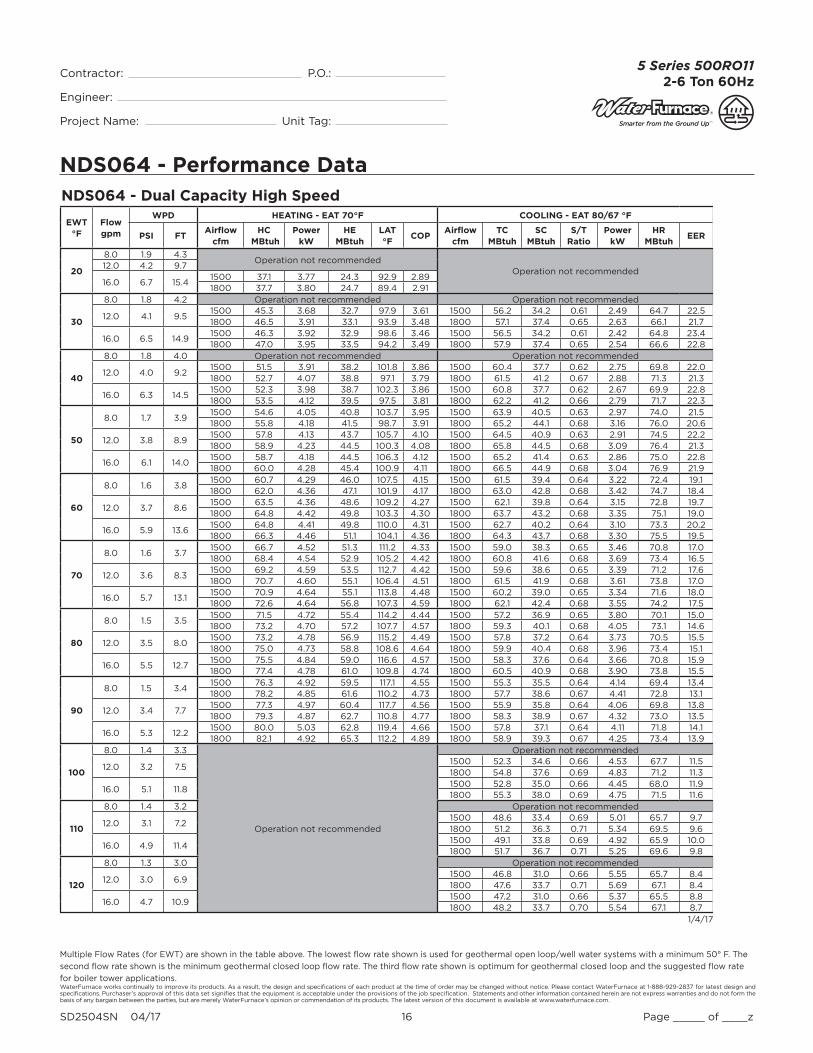
SD2504SN 04/17 16 Page _____ of ____z
5 Series 500RO112-6 Ton 60Hz
NDS064 - Performance Data
Multiple Flow Rates (for EWT) are shown in the table above. The lowest fl ow rate shown is used for geothermal open loop/well water systems with a minimum 50° F. The
second fl ow rate shown is the minimum geothermal closed loop fl ow rate. The third fl ow rate shown is optimum for geothermal closed loop and the suggested fl ow rate
for boiler tower applications.
NDS064 - Dual Capacity High Speed
EWT °F
Flow gpm
WPD HEATING - EAT 70°F COOLING - EAT 80/67 °F
PSI FTAirflow
cfmHC
MBtuhPower
kWHE
MBtuhLAT °F
COPAirflow
cfmTC
MBtuhSC
MBtuhS/T
RatioPower
kWHR
MBtuhEER
20
8.0 1.9 4.3Operation not recommended
Operation not recommended12.0 4.2 9.7
16.0 6.7 15.41500 37.1 3.77 24.3 92.9 2.891800 37.7 3.80 24.7 89.4 2.91
30
8.0 1.8 4.2 Operation not recommended Operation not recommended
12.0 4.1 9.51500 45.3 3.68 32.7 97.9 3.61 1500 56.2 34.2 0.61 2.49 64.7 22.51800 46.5 3.91 33.1 93.9 3.48 1800 57.1 37.4 0.65 2.63 66.1 21.7
16.0 6.5 14.91500 46.3 3.92 32.9 98.6 3.46 1500 56.5 34.2 0.61 2.42 64.8 23.41800 47.0 3.95 33.5 94.2 3.49 1800 57.9 37.4 0.65 2.54 66.6 22.8
40
8.0 1.8 4.0 Operation not recommended Operation not recommended
12.0 4.0 9.21500 51.5 3.91 38.2 101.8 3.86 1500 60.4 37.7 0.62 2.75 69.8 22.01800 52.7 4.07 38.8 97.1 3.79 1800 61.5 41.2 0.67 2.88 71.3 21.3
16.0 6.3 14.51500 52.3 3.98 38.7 102.3 3.86 1500 60.8 37.7 0.62 2.67 69.9 22.81800 53.5 4.12 39.5 97.5 3.81 1800 62.2 41.2 0.66 2.79 71.7 22.3
50
8.0 1.7 3.91500 54.6 4.05 40.8 103.7 3.95 1500 63.9 40.5 0.63 2.97 74.0 21.51800 55.8 4.18 41.5 98.7 3.91 1800 65.2 44.1 0.68 3.16 76.0 20.6
12.0 3.8 8.91500 57.8 4.13 43.7 105.7 4.10 1500 64.5 40.9 0.63 2.91 74.5 22.21800 58.9 4.23 44.5 100.3 4.08 1800 65.8 44.5 0.68 3.09 76.4 21.3
16.0 6.1 14.01500 58.7 4.18 44.5 106.3 4.12 1500 65.2 41.4 0.63 2.86 75.0 22.81800 60.0 4.28 45.4 100.9 4.11 1800 66.5 44.9 0.68 3.04 76.9 21.9
60
8.0 1.6 3.81500 60.7 4.29 46.0 107.5 4.15 1500 61.5 39.4 0.64 3.22 72.4 19.11800 62.0 4.36 47.1 101.9 4.17 1800 63.0 42.8 0.68 3.42 74.7 18.4
12.0 3.7 8.61500 63.5 4.36 48.6 109.2 4.27 1500 62.1 39.8 0.64 3.15 72.8 19.71800 64.8 4.42 49.8 103.3 4.30 1800 63.7 43.2 0.68 3.35 75.1 19.0
16.0 5.9 13.61500 64.8 4.41 49.8 110.0 4.31 1500 62.7 40.2 0.64 3.10 73.3 20.21800 66.3 4.46 51.1 104.1 4.36 1800 64.3 43.7 0.68 3.30 75.5 19.5
70
8.0 1.6 3.71500 66.7 4.52 51.3 111.2 4.33 1500 59.0 38.3 0.65 3.46 70.8 17.01800 68.4 4.54 52.9 105.2 4.42 1800 60.8 41.6 0.68 3.69 73.4 16.5
12.0 3.6 8.31500 69.2 4.59 53.5 112.7 4.42 1500 59.6 38.6 0.65 3.39 71.2 17.61800 70.7 4.60 55.1 106.4 4.51 1800 61.5 41.9 0.68 3.61 73.8 17.0
16.0 5.7 13.11500 70.9 4.64 55.1 113.8 4.48 1500 60.2 39.0 0.65 3.34 71.6 18.01800 72.6 4.64 56.8 107.3 4.59 1800 62.1 42.4 0.68 3.55 74.2 17.5
80
8.0 1.5 3.51500 71.5 4.72 55.4 114.2 4.44 1500 57.2 36.9 0.65 3.80 70.1 15.01800 73.2 4.70 57.2 107.7 4.57 1800 59.3 40.1 0.68 4.05 73.1 14.6
12.0 3.5 8.01500 73.2 4.78 56.9 115.2 4.49 1500 57.8 37.2 0.64 3.73 70.5 15.51800 75.0 4.73 58.8 108.6 4.64 1800 59.9 40.4 0.68 3.96 73.4 15.1
16.0 5.5 12.71500 75.5 4.84 59.0 116.6 4.57 1500 58.3 37.6 0.64 3.66 70.8 15.91800 77.4 4.78 61.0 109.8 4.74 1800 60.5 40.9 0.68 3.90 73.8 15.5
90
8.0 1.5 3.41500 76.3 4.92 59.5 117.1 4.55 1500 55.3 35.5 0.64 4.14 69.4 13.41800 78.2 4.85 61.6 110.2 4.73 1800 57.7 38.6 0.67 4.41 72.8 13.1
12.0 3.4 7.71500 77.3 4.97 60.4 117.7 4.56 1500 55.9 35.8 0.64 4.06 69.8 13.81800 79.3 4.87 62.7 110.8 4.77 1800 58.3 38.9 0.67 4.32 73.0 13.5
16.0 5.3 12.21500 80.0 5.03 62.8 119.4 4.66 1500 57.8 37.1 0.64 4.11 71.8 14.11800 82.1 4.92 65.3 112.2 4.89 1800 58.9 39.3 0.67 4.25 73.4 13.9
100
8.0 1.4 3.3
Operation not recommended
Operation not recommended
12.0 3.2 7.51500 52.3 34.6 0.66 4.53 67.7 11.51800 54.8 37.6 0.69 4.83 71.2 11.3
16.0 5.1 11.81500 52.8 35.0 0.66 4.45 68.0 11.91800 55.3 38.0 0.69 4.75 71.5 11.6
110
8.0 1.4 3.2 Operation not recommended
12.0 3.1 7.21500 48.6 33.4 0.69 5.01 65.7 9.71800 51.2 36.3 0.71 5.34 69.5 9.6
16.0 4.9 11.41500 49.1 33.8 0.69 4.92 65.9 10.01800 51.7 36.7 0.71 5.25 69.6 9.8
120
8.0 1.3 3.0 Operation not recommended
12.0 3.0 6.91500 46.8 31.0 0.66 5.55 65.7 8.41800 47.6 33.7 0.71 5.69 67.1 8.4
16.0 4.7 10.91500 47.2 31.0 0.66 5.37 65.5 8.81800 48.2 33.7 0.70 5.54 67.1 8.7
1/4/17

WaterFurnace works continually to improve its products. As a result, the design and specifi cations of each product at the time of order may be changed without notice. Please contact WaterFurnace at 1-888-929-2837 for latest design and specifi cations. Purchaser’s approval of this data set signifi es that the equipment is acceptable under the provisions of the job specifi cation. Statements and other information contained herein are not express warranties and do not form the basis of any bargain between the parties, but are merely WaterFurnace’s opinion or commendation of its products. The latest version of this document is available at www.waterfurnace.com.
Contractor: P.O.: Engineer:
Project Name: Unit Tag:
SD2504SN 04/17 17 Page _____ of ____z
5 Series 500RO112-6 Ton 60Hz
NDS072 - Performance Data
Multiple Flow Rates (for EWT) are shown in the table above. The lowest fl ow rate shown is used for geothermal open loop/well water systems with a minimum 50° F. The
second fl ow rate shown is the minimum geothermal closed loop fl ow rate. The third fl ow rate shown is optimum for geothermal closed loop and the suggested fl ow rate
for boiler tower applications.
NDS072 - Dual Capacity Low Speed
EWT °F
Flow gpm
WPD HEATING - EAT 70°F COOLING - EAT 80/67 °F
PSI FTAirflow
cfmHC
MBtuhPower
kWHE
MBtuhLAT °F
COPAirflow
cfmTC
MBtuhSC
MBtuhS/T
RatioPower
kWHR
MBtuhEER
20
10.0 2.5 5.7Operation not recommended
Operation not recommended13.0 4.1 9.5
16.0 5.7 13.21400 35.8 3.77 22.9 93.7 2.781600 36.2 3.71 23.5 90.9 2.86
30
10.0 2.4 5.6 Operation not recommended Operation not recommended
13.0 4.0 9.21400 38.8 3.84 25.7 95.6 2.96 1400 50.6 30.1 0.60 1.76 56.6 28.81600 40.7 3.89 27.4 93.6 3.07 1600 51.4 32.9 0.64 1.85 57.7 27.8
16.0 5.6 12.81400 41.9 3.95 28.4 97.7 3.11 1400 50.9 30.1 0.59 1.70 56.7 29.81600 42.4 3.89 29.1 94.5 3.19 1600 52.1 32.9 0.63 1.79 58.2 29.1
40
10.0 2.3 5.4 Operation not recommended Operation not recommended
13.0 3.9 8.91400 44.9 4.00 31.2 99.7 3.29 1400 54.4 33.4 0.61 1.98 61.2 27.51600 46.8 4.01 33.1 97.1 3.42 1600 55.4 36.5 0.66 2.08 62.5 26.7
16.0 5.4 12.51400 46.4 4.01 32.7 100.7 3.39 1400 54.8 33.4 0.61 1.92 61.4 28.51600 48.5 4.03 34.8 98.1 3.53 1600 56.1 36.5 0.65 2.01 62.9 27.9
50
10.0 2.3 5.21400 50.1 4.12 36.1 103.2 3.57 1400 57.9 35.0 0.60 2.25 64.6 25.81600 52.4 4.07 38.5 100.3 3.77 1600 59.7 39.7 0.66 2.36 66.8 25.2
13.0 3.7 8.61400 50.9 4.16 36.7 103.7 3.59 1400 58.1 35.3 0.61 2.17 65.5 26.71600 52.9 4.14 38.8 100.6 3.75 1600 59.9 40.1 0.67 2.29 67.3 26.2
16.0 5.2 12.11400 52.4 4.18 38.1 104.6 3.67 1400 58.2 35.3 0.61 2.11 66.0 27.51600 54.6 4.16 40.4 101.6 3.85 1600 60.0 40.1 0.67 2.23 67.6 26.9
60
10.0 2.2 5.11400 55.5 4.24 41.0 106.7 3.83 1400 55.2 34.3 0.62 2.60 63.7 21.21600 57.8 4.16 43.7 103.5 4.08 1600 56.9 38.7 0.68 2.72 65.8 20.9
13.0 3.6 8.41400 57.1 4.29 42.4 107.7 3.90 1400 55.4 34.6 0.62 2.52 64.0 22.01600 59.3 4.21 44.9 104.3 4.13 1600 57.1 39.1 0.69 2.63 66.1 21.7
16.0 5.1 11.71400 58.4 4.33 43.6 108.6 3.95 1400 55.7 34.7 0.62 2.47 64.4 22.51600 60.7 4.26 46.2 105.1 4.18 1600 57.4 39.2 0.68 2.58 66.2 22.3
70
10.0 2.1 4.91400 60.9 4.37 46.0 110.3 4.08 1400 52.5 33.5 0.64 2.96 62.3 17.81600 64.5 4.33 49.7 107.3 4.37 1600 54.0 37.7 0.70 3.07 64.1 17.6
13.0 3.5 8.11400 63.2 4.41 48.1 111.8 4.19 1400 52.8 33.9 0.64 2.86 62.6 18.51600 65.6 4.29 51.0 108.0 4.49 1600 54.3 38.2 0.70 2.98 64.5 18.3
16.0 4.9 11.31400 64.3 4.48 49.0 112.5 4.21 1400 53.1 34.1 0.64 2.82 62.8 18.81600 66.8 4.35 52.0 108.7 4.50 1600 54.8 38.3 0.70 2.92 64.8 18.8
80
10.0 2.0 4.71400 65.4 4.49 50.1 113.3 4.27 1400 48.2 32.1 0.67 3.35 59.7 14.41600 67.8 4.33 53.0 109.2 4.59 1600 51.2 35.9 0.70 3.45 63.0 14.9
13.0 3.4 7.81400 68.9 4.55 53.3 115.5 4.44 1400 50.1 32.5 0.65 3.27 61.3 15.31600 71.3 4.36 56.4 111.3 4.79 1600 51.6 36.3 0.70 3.36 63.1 15.4
16.0 4.7 10.91400 69.7 4.61 53.9 116.1 4.43 1400 50.5 32.7 0.65 3.22 61.5 15.71600 72.1 4.44 56.9 111.7 4.76 1600 50.5 36.6 0.72 3.31 61.8 15.3
90
10.0 2.0 4.61400 70.0 4.62 54.2 116.3 4.44 1400 43.9 30.7 0.70 3.75 56.7 11.71600 72.3 4.42 57.2 111.8 4.79 1600 45.3 34.1 0.75 3.83 58.3 11.8
13.0 3.3 7.51400 74.5 4.68 58.5 119.3 4.67 1400 44.4 31.0 0.70 3.67 57.7 12.11600 77.0 4.44 61.8 114.6 5.08 1600 45.7 34.5 0.75 3.75 58.5 12.2
16.0 4.6 10.51400 75.0 4.74 58.8 119.6 4.63 1400 46.8 33.2 0.71 3.73 59.5 12.51600 77.3 4.53 61.8 114.7 5.00 1600 46.2 34.8 0.75 3.69 58.8 12.5
100
10.0 1.9 4.4
Operation not recommended
Operation not recommended
13.0 3.1 7.31400 41.9 29.6 0.71 4.30 56.5 9.71600 43.2 32.7 0.76 4.35 58.1 9.9
16.0 4.4 10.11400 42.4 29.9 0.70 4.23 56.9 10.01600 43.7 33.1 0.76 4.29 58.3 10.2
110
10.0 1.8 4.2 Operation not recommended
13.0 3.0 7.01400 39.4 28.1 0.71 4.92 56.2 8.01600 40.7 31.0 0.76 4.95 57.6 8.2
16.0 4.2 9.81400 40.0 28.5 0.71 4.86 56.6 8.21600 41.2 31.4 0.76 4.88 57.9 8.4
120
10.0 1.8 4.1 Operation not recommended
13.0 2.9 6.71400 37.5 28.1 0.75 5.49 56.2 6.81600 38.1 30.5 0.80 5.63 57.4 6.8
16.0 4.1 9.41400 37.8 28.1 0.74 5.31 55.9 7.11600 38.6 30.5 0.79 5.48 57.3 7.0
1/4/17

WaterFurnace works continually to improve its products. As a result, the design and specifi cations of each product at the time of order may be changed without notice. Please contact WaterFurnace at 1-888-929-2837 for latest design and specifi cations. Purchaser’s approval of this data set signifi es that the equipment is acceptable under the provisions of the job specifi cation. Statements and other information contained herein are not express warranties and do not form the basis of any bargain between the parties, but are merely WaterFurnace’s opinion or commendation of its products. The latest version of this document is available at www.waterfurnace.com.
Contractor: P.O.: Engineer:
Project Name: Unit Tag:
SD2504SN 04/17 18 Page _____ of ____z
5 Series 500RO112-6 Ton 60Hz
NDS072 - Performance Data
Multiple Flow Rates (for EWT) are shown in the table above. The lowest fl ow rate shown is used for geothermal open loop/well water systems with a minimum 50° F. The
second fl ow rate shown is the minimum geothermal closed loop fl ow rate. The third fl ow rate shown is optimum for geothermal closed loop and the suggested fl ow rate
for boiler tower applications.
NDS072 - Dual Capacity High Speed
EWT °F
Flow gpm
WPD HEATING - EAT 70°F COOLING - EAT 80/67 °F
PSI FTAirflow
cfmHC
MBtuhPower
kWHE
MBtuhLAT °F
COPAirflow
cfmTC
MBtuhSC
MBtuhS/T
RatioPower
kWHR
MBtuhEER
20
12.0 3.4 7.9Operation not recommended
Operation not recommended15.0 5.1 11.9
18.0 7.0 16.11800 36.7 4.41 21.6 88.9 2.442000 37.0 4.43 21.9 87.1 2.45
30
12.0 3.3 7.7 Operation not recommended Operation not recommended
15.0 5.0 11.61800 54.7 4.80 38.3 98.1 3.34 1800 62.7 37.3 0.60 2.87 72.5 21.92000 56.6 5.11 39.2 96.2 3.25 2000 63.8 40.8 0.64 3.02 74.1 21.1
18.0 6.8 15.61800 56.7 5.14 39.2 99.2 3.23 1800 63.1 37.3 0.59 2.78 72.6 22.72000 57.2 5.16 39.6 96.5 3.25 2000 64.6 40.8 0.63 2.92 74.6 22.1
40
12.0 3.2 7.5 Operation not recommended Operation not recommended
15.0 4.8 11.21800 61.8 5.07 44.5 101.8 3.57 1800 67.5 41.4 0.61 3.17 78.3 21.32000 63.9 5.30 45.8 99.6 3.53 2000 68.7 45.2 0.66 3.32 80.1 20.7
18.0 6.6 15.21800 62.6 5.12 45.2 102.2 3.58 1800 68.0 41.4 0.61 3.07 78.5 22.12000 64.8 5.36 46.5 100.0 3.55 2000 69.5 45.2 0.65 3.22 80.5 21.6
50
12.0 3.1 7.21800 65.2 5.22 47.4 103.5 3.66 1800 71.5 44.7 0.63 3.43 83.2 20.92000 67.4 5.41 48.9 101.2 3.65 2000 73.0 48.6 0.67 3.64 85.4 20.1
15.0 4.7 10.91800 68.9 5.32 50.7 105.4 3.79 1800 72.2 45.2 0.63 3.35 83.7 21.52000 71.1 5.50 52.4 102.9 3.79 2000 73.6 49.1 0.67 3.57 85.8 20.7
18.0 6.4 14.71800 70.1 5.39 51.7 106.1 3.81 1800 73.0 46.1 0.63 3.30 84.2 22.12000 72.4 5.55 53.5 103.5 3.82 2000 74.4 49.6 0.67 3.51 86.4 21.2
60
12.0 3.0 7.01800 74.1 5.46 55.5 108.1 3.98 1800 67.7 43.8 0.65 3.74 80.4 18.12000 76.5 5.57 57.5 105.4 4.03 2000 69.1 47.3 0.68 3.98 82.6 17.4
15.0 4.5 10.51800 77.3 5.55 58.4 109.8 4.08 1800 68.3 44.2 0.65 3.67 80.8 18.62000 79.9 5.64 60.6 107.0 4.15 2000 69.7 47.8 0.69 3.89 83.0 17.9
18.0 6.2 14.21800 79.1 5.62 59.9 110.7 4.13 1800 69.1 44.9 0.65 3.60 81.4 19.22000 81.7 5.70 62.3 107.8 4.20 2000 70.5 48.3 0.69 3.84 83.5 18.4
70
12.0 2.9 6.81800 82.9 5.68 63.5 112.7 4.28 1800 63.8 42.8 0.67 4.06 77.7 15.72000 84.7 5.88 64.6 109.2 4.22 2000 65.2 46.0 0.71 4.32 79.9 15.1
15.0 4.4 10.21800 85.9 5.77 66.2 114.2 4.36 1800 64.5 43.2 0.67 3.98 78.0 16.22000 88.6 5.78 68.8 111.0 4.49 2000 65.8 46.5 0.71 4.22 80.2 15.6
18.0 6.0 13.81800 88.1 5.85 68.1 115.3 4.42 1800 65.2 43.7 0.67 3.90 78.5 16.72000 91.0 5.85 71.0 112.1 4.56 2000 66.5 47.0 0.71 4.16 80.7 16.0
80
12.0 2.8 6.51800 87.8 6.00 67.3 115.2 4.29 1800 60.6 40.9 0.67 4.52 76.0 13.42000 91.1 6.03 70.5 112.2 4.43 2000 61.9 44.2 0.71 4.80 78.3 12.9
15.0 4.3 9.81800 90.3 6.15 69.3 116.5 4.30 1800 61.2 41.3 0.67 4.42 76.3 13.82000 93.2 6.07 72.5 113.1 4.50 2000 62.5 44.6 0.71 4.71 78.5 13.3
18.0 5.7 13.31800 93.1 6.23 71.8 117.9 4.38 1800 61.9 41.9 0.68 4.35 76.7 14.22000 96.1 6.14 75.2 114.5 4.59 2000 63.2 45.1 0.71 4.63 78.9 13.6
90
12.0 2.7 6.31800 93.5 6.46 71.4 118.1 4.24 1800 57.4 38.9 0.68 4.97 74.4 11.52000 96.6 6.33 75.0 114.7 4.47 2000 58.6 42.3 0.72 5.29 76.7 11.1
15.0 4.1 9.51800 94.8 6.53 72.5 118.8 4.25 1800 58.0 39.3 0.68 4.87 74.6 11.92000 97.9 6.36 76.2 115.3 4.51 2000 59.2 42.7 0.72 5.19 76.9 11.4
18.0 5.5 12.81800 98.0 6.62 75.5 120.4 4.34 1800 59.8 41.5 0.69 4.98 76.8 12.02000 101.3 6.43 79.4 116.9 4.62 2000 59.8 43.1 0.72 5.10 77.2 11.7
100
12.0 2.6 6.1
Operation not recommended
Operation not recommended
15.0 4.0 9.11800 54.4 37.6 0.69 5.45 73.0 10.02000 55.5 40.7 0.73 5.80 75.3 9.6
18.0 5.3 12.31800 55.0 38.2 0.69 5.36 73.3 10.32000 56.2 41.1 0.73 5.70 75.6 9.9
110
12.0 2.5 5.8 Operation not recommended
15.0 3.8 8.81800 50.9 36.0 0.71 6.03 71.4 8.42000 51.9 38.7 0.75 6.41 73.8 8.1
18.0 5.1 11.91800 51.4 36.4 0.71 5.92 71.7 8.72000 52.5 39.1 0.74 6.30 74.0 8.3
120
12.0 2.4 5.6 Operation not recommended
15.0 3.7 8.41800 48.5 36.8 0.76 6.95 72.3 7.02000 49.4 39.9 0.81 7.13 73.8 6.9
18.0 4.9 11.41800 49.0 36.8 0.75 6.73 71.9 7.32000 50.0 39.9 0.80 6.94 73.7 7.2
1/4/17

WaterFurnace works continually to improve its products. As a result, the design and specifi cations of each product at the time of order may be changed without notice. Please contact WaterFurnace at 1-888-929-2837 for latest design and specifi cations. Purchaser’s approval of this data set signifi es that the equipment is acceptable under the provisions of the job specifi cation. Statements and other information contained herein are not express warranties and do not form the basis of any bargain between the parties, but are merely WaterFurnace’s opinion or commendation of its products. The latest version of this document is available at www.waterfurnace.com.
Contractor: P.O.: Engineer:
Project Name: Unit Tag:
SD2504SN 04/17 19 Page _____ of ____z
5 Series 500RO112-6 Ton 60Hz
Wiring SchematicsDual Capacity Split - 208-230/60/1
Compressor
CCT2 T1
C
R
SBlue
G L1L2
Black
208-230/60/1Unit Power Supply
Black(2)
RedTan(16)
Black(1)
Cap
Violet(7)
Circuit Breaker
Circuit Breaker
5A
5A
5
2 4RP
Violet(6)
Black(3)
FP
Red(11) Red(12)
Crankcase Heater
Black
Black
1
2
PB1
1
2
1
Ext Pump 1/2 hp Total 208-230/60/1
PumpPump Yellow(8)
Gray(9)G
GGreen(17)Ground Lug
Note 1
Flow Center
UltraTech
RCP
CS
Blue(16)Blue(18)
AID Tool
RV
CC
HP
Black
Black
Blue
Blue
LP
T
Yellow
Yellow
FP1
Orange
Orange
RV
Black(15)
Violet(14)
Green(18)
CFM
P13
P4
SW1
P5JW2
P9
LO
O/B
Y2WDH
P8 P7
RS485 NET RS485 NET
P6
RS485 EXP
P3
SW2
On
Future Use L Output Type
CC – Dual/SingleAcc – Dip 5Acc – Dip 4
RV – B/OFP2 – 15°F/30°FFP1 – 15°F/30°F
Com1LED5
Com2LED5
Test Mode
F1-3A
P1
C
PWM
12345678
ALMALGACC COMACC NOACC NC
RC
GY1
EH2CEH1CCOC R - +C R - +
Off
FaultLED1
R
StatusLED3
ConfigLED2
CC2 CC F C R F FG CC CCGCC2HI
CC2LO
CC2G REVREV FP1 FP1 FP2 FP2 LPS LPS HPSHPS
Aurora Base Control(ABC)
K1-RV Rel ay
K2-CC Relay
K3-CC2 Relay
K4-F an Re layK5-Alarm Relay
K6-Acc Relay
F
R
C
CCGY1C
R
ESLS
P2
EH1
YG G
G
RP
White(4) Blue(5)
3 1
WaterFurnace works continually to improve its products. As a result, the design and specifi cations of each product at the time of order may be changed without notice. Please contact WaterFurnace at 1-888-929-2837 for latest design and specifi cations. Purchaser’s approval of this data set signifi es that the equipment is acceptable under the provisions of the job specifi cation. Statements and other information contained herein are not express warranties and do not form the basis of any bargain between the parties, but are merely WaterFurnace’s opinion or commendation of its products. The latest version of this document is available at www.waterfurnace.com.
Contractor: P.O.: Engineer:
Project Name: Unit Tag:
SD2504SN 04/17 20 Page _____ of ____z
5 Series 500RO112-6 Ton 60Hz
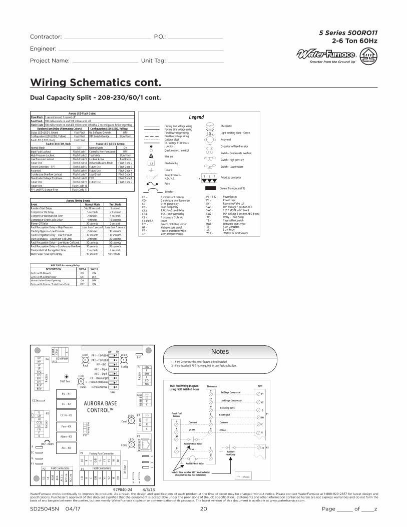
Wiring Schematics cont.Dual Capacity Split - 208-230/60/1 cont.
4/3/1397P840-24
Y1
Y2
O
R
C
L
C
R
Fossil Fuel Furnace
Thermostat
24 VAC
Common Common
24 VAC
Fault Signal
Reversing Valve
2nd Stage Compressor
1st Stage Compressor Y1
Y2
O
R
C
LO
Split
GG Fan
W
W
Auxiliary Heat Relay
Duel Fuel Wiring DiagramUsing Field Installed Relay
Note 2: Field installed SPST dual fuel relay (Required for dual fuel installation)
Auxiliary Heat RelayP2
P1
Auxiliary Heat Relay
ES
= chassis
Notes1 – Flow Center may be either factory or field installed.2 – Field installed SPST relay required for duel fuel applications.
Aurora LED Flash Codes
Status LED (LED3, Green)
Status LED (LED1, Green)Configuration LED (LED2, Yellow)Fault LED (LED3, Red)
Random Start Delay (Alternating Colors)Fast FlashFast FlashFast Flash
1 second on and 1 second off100 milliseconds on and 100 milliseconds off100 milliseconds on and 400 milliseconds off with a 2 second pause before repeating
Slow FlashFast FlashFlash Code
Normal ModeControl is Non-FunctionalTest ModeLockout ActiveDehumidification ModeFuture UseFuture UseLoad ShedESD
OFFON
Slow FlashFast Flash
Flash Code 2Flash Code 3
Flash Code 6
Flash Code 4Flash Code 5
Future Use Flash Code 7
Configuration LED (LED2, Yellow)No Software Overide OFFDIP Switch Overide Slow Flash
Fault LED (LED1, Red)Normal ModeInput Fault LockoutHigh Pressure LockoutLow Pressure LockoutFuture UseFreeze Detection – FP1ReservedCondensate Overflow LockoutOver/Under Voltage ShutdownFuture UseFuture UseFP1 and FP2 Sensor Error
Flash Code 1OFF
Flash Code 2Flash Code 3Flash Code 4Flash Code 5
Flash Code 8
Flash Code 6Flash Code 7
Flash Code 9Flash Code 10Flash Code 11
DESCRIPTION SW2-4 SW2-5Cycle with Blower ON ONCycle with Compressor OFF OFFWater Valve Slow Opening ON OFFCycle with Comm. T-stat Hum Cmd OFF ON
ABC SW2 Accessory Relay
Event Normal Mode Test ModeRandom Start DelayCompressor On DelayCompressor Minimum On TimeCompressor Short Cycle DelayBlower Off DelayFault Recognition Delay – High PressureStart-Up Bypass – Low PressureFault Recognition Delay – Low PressureStart-Up Bypass – Low Water Coil LimitFault Recognition Delay – Low Water Coil LimitFault Recognition Delay – Condensate OverflowThermostat Call Recognition Time
Less than 1 second
5 to 80 seconds 1 second5 seconds < 1 second
30 seconds 2 secondsLess than 1 second
2 minutes 5 seconds4 minutes 15 seconds
2 minutes
2 minutes
30 seconds30 seconds 30 seconds
30 seconds30 seconds
30 seconds30 seconds30 seconds
2 seconds 2 seconds
Aurora Timing Events
Water Valve Slow Open Delay 90 seconds90 seconds
CC2
Facto
ry
Fault
ALG
ALMLSES ACC
c
Status
AURORA BASE CONTROL™
RV – K1
CC2
CC – K2
CC Hi – K3
Fan – K4
Alarm – K5
Acc – K6
ACC
noAC
C nc
O/BCRLO G Y1 Y2 W DH
3A-F
use
O/BCRLO G Y1 Y2 W DH
LOG
HICCGCCFGFR
HPHPLP
FP2FP2FP1
REVREV
CFM
PWM
ECM PWM
Facto
ry
Factory Fan Connection
R R
CC
C
CR(-)(+)
RS 48
5
EH2C
EH1C
CO
(+)(-)RCRS
485 E
xpFa
ctory
Com1
Com2
Config
G
G
G
YR
SW1 Test
FP1 – 15oF/30oF
JW2 - Alarm
P11
P5
P2 P1
P8
P7
P9
P6
P3
SW2
P13P4 FP2 – 15oF/30oF
RV – B/OACC – Dip 4ACC – Dip 5
CC – Dual/Single L – Pulse/Continuous
Reheat/Normal
Facto
ry Us
e
Field ConnectionsField Connections
C
LP
FP1
F
CC
G
Y1
12345678
Off On
N/A
RS48
5 NET
EH1LED1
LED3
LED2
LED4
LED5
Current Transducer (CT)
Thermistor
Light emitting diode - Green
Relay coil
Capacitor w/ bleed resistor
Switch - Condensate overflow
Switch - High pressure
Switch - Low pressure
Polarized connector
Factory Low voltage wiringFactory Line voltage wiringField low voltage wiringField line voltage wiringOptional blockDC Voltage PCB tracesJunctionQuick connect terminal
Wire nut
Field wire lug
Ground
Fuse
CC -CO -K5 -K6 -CR3 -CR4 -
F1 and F2 -
WCL -
FP1 -HP -
LP -
PB1, PB2 - PS -RV -SW1 -SW1 -SW2 -
TS -
Compressor ContactorCondensate overflow sensorDHW pump relayLoop pump relay
Fuses
Water Coil Limit Sensor
Freeze protection sensorHigh pressure switch
Low pressure switch
Power blocksPower stripReversing Valve coilDIP package 5 position AXBTEST MODE ABC BoardDIP package 8 position ABC Board
Thermal limit switch
Legend
Relay Contacts-N.O., N.C.
G
T
132P
L1
PSC Fan Speed RelayPSC Fan Power Relay
HWL - Hot water limit sensorSC - Start Contactor
Start RelaySR -
CS - Compressor Solenoid
Breaker
RP - Relay – Loop Pump
Freeze protection switchFP -
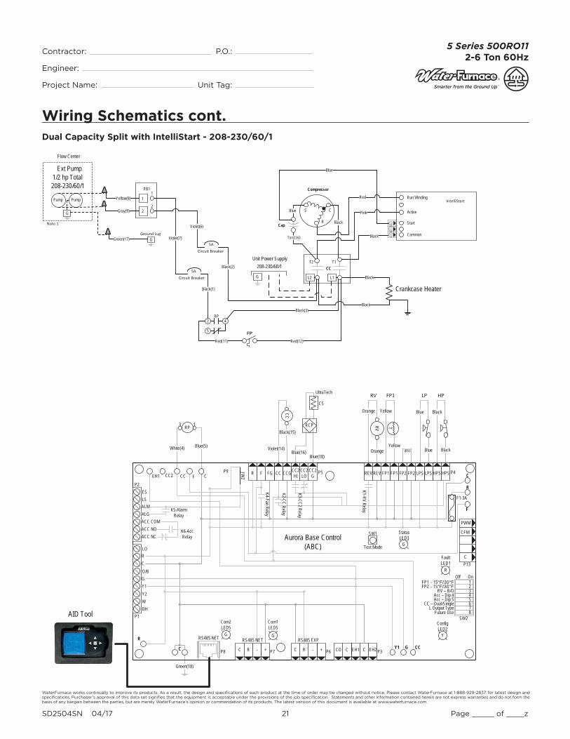
WaterFurnace works continually to improve its products. As a result, the design and specifi cations of each product at the time of order may be changed without notice. Please contact WaterFurnace at 1-888-929-2837 for latest design and specifi cations. Purchaser’s approval of this data set signifi es that the equipment is acceptable under the provisions of the job specifi cation. Statements and other information contained herein are not express warranties and do not form the basis of any bargain between the parties, but are merely WaterFurnace’s opinion or commendation of its products. The latest version of this document is available at www.waterfurnace.com.
Contractor: P.O.: Engineer:
Project Name: Unit Tag:
SD2504SN 04/17 21 Page _____ of ____z
5 Series 500RO112-6 Ton 60Hz
Wiring Schematics cont.Dual Capacity Split with IntelliStart - 208-230/60/1
Compressor
CCT2 T1
C
R
SBlue
G L1L2
208-230/60/1Unit Power Supply
Black(2)
Tan(16)
Black(1)
Cap
Violet(7)
Circuit Breaker
Circuit Breaker
5A
5A
5
2 4RP
Violet(6)
Black(3)
FP
Red(11) Red(12)
Crankcase Heater
Black
Black
Run Winding
Active
Start
Common
IntelliStart
Black
Blue
Red
Pink
Black
1
2
PB1
1
2
1
Ext Pump 1/2 hp Total 208-230/60/1
PumpPump Yellow(8)
Gray(9)G
GGreen(17)Ground Lug
Note 1
Flow Center
UltraTech
RCP
CS
Blue(16)Blue(18)
AID Tool
RV
CC
HP
Black
Black
Blue
Blue
LP
T
Yellow
Yellow
FP1
Orange
Orange
RV
Black(15)
Violet(14)
Green(18)
CFM
P13
P4
SW1
P5JW2
P9
LO
O/B
Y2WDH
P8 P7
RS485 NET RS485 NET
P6
RS485 EXP
P3
SW2
On
Future Use L Output Type
CC – Dual/SingleAcc – Dip 5Acc – Dip 4
RV – B/OFP2 – 15°F/30°FFP1 – 15°F/30°F
Com1LED5
Com2LED5
Test Mode
F1-3A
P1
C
PWM
12345678
ALMALGACC COMACC NOACC NC
RC
GY1
EH2CEH1CCOC R - +C R - +
Off
FaultLED1
R
StatusLED3
ConfigLED2
CC2 CC F C R F FG CC CCGCC2HI
CC2LO
CC2G REVREV FP1 FP1 FP2 FP2 LPS LPS HPS HPS
Aurora Base Control(ABC)
K1-RV Relay
K2-CC Relay
K3-CC2 Relay
K4-Fan RelayK5-Alarm Relay
K6-Acc Relay
F
R
C
CCGY1C
R
ESLS
P2
EH1
YG G
G
RP
White(4) Blue(5)
3 1
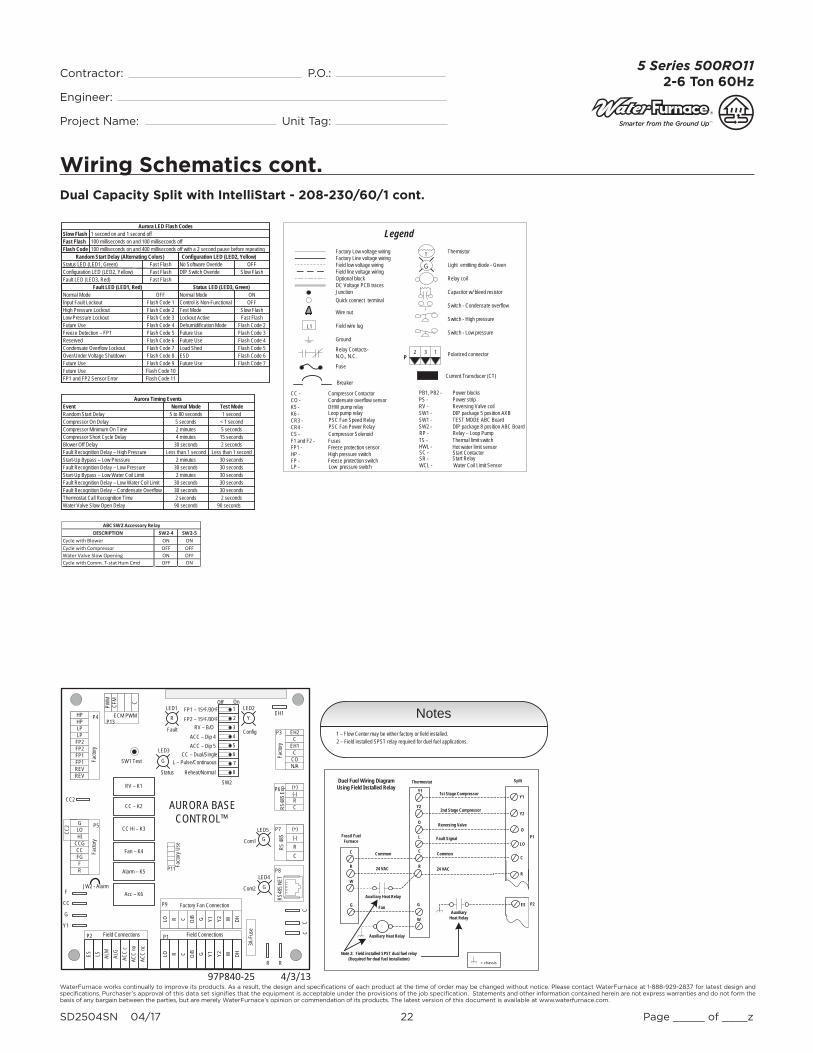
WaterFurnace works continually to improve its products. As a result, the design and specifi cations of each product at the time of order may be changed without notice. Please contact WaterFurnace at 1-888-929-2837 for latest design and specifi cations. Purchaser’s approval of this data set signifi es that the equipment is acceptable under the provisions of the job specifi cation. Statements and other information contained herein are not express warranties and do not form the basis of any bargain between the parties, but are merely WaterFurnace’s opinion or commendation of its products. The latest version of this document is available at www.waterfurnace.com.
Contractor: P.O.: Engineer:
Project Name: Unit Tag:
SD2504SN 04/17 22 Page _____ of ____z
5 Series 500RO112-6 Ton 60Hz
Wiring Schematics cont.Dual Capacity Split with IntelliStart - 208-230/60/1 cont.
4/3/1397P840-25
Aurora LED Flash Codes
Status LED (LED3, Green)
Status LED (LED1, Green)Configuration LED (LED2, Yellow)Fault LED (LED3, Red)
Random Start Delay (Alternating Colors)Fast FlashFast FlashFast Flash
1 second on and 1 second off100 milliseconds on and 100 milliseconds off100 milliseconds on and 400 milliseconds off with a 2 second pause before repeating
Slow FlashFast FlashFlash Code
Normal ModeControl is Non-FunctionalTest ModeLockout ActiveDehumidification ModeFuture UseFuture UseLoad ShedESD
OFFON
Slow FlashFast Flash
Flash Code 2Flash Code 3
Flash Code 6
Flash Code 4Flash Code 5
Future Use Flash Code 7
Configuration LED (LED2, Yellow)No Software Overide OFFDIP Switch Overide Slow Flash
Fault LED (LED1, Red)Normal ModeInput Fault LockoutHigh Pressure LockoutLow Pressure LockoutFuture UseFreeze Detection – FP1ReservedCondensate Overflow LockoutOver/Under Voltage ShutdownFuture UseFuture UseFP1 and FP2 Sensor Error
Flash Code 1OFF
Flash Code 2Flash Code 3Flash Code 4Flash Code 5
Flash Code 8
Flash Code 6Flash Code 7
Flash Code 9Flash Code 10Flash Code 11
DESCRIPTION SW2-4 SW2-5Cycle with Blower ON ONCycle with Compressor OFF OFFWater Valve Slow Opening ON OFFCycle with Comm. T-stat Hum Cmd OFF ON
ABC SW2 Accessory Relay
Y1
Y2
O
R
C
L
C
R
Fossil Fuel Furnace
Thermostat
24 VAC
Common Common
24 VAC
Fault Signal
Reversing Valve
2nd Stage Compressor
1st Stage Compressor Y1
Y2
O
R
C
LO
Split
GG Fan
W
W
Auxiliary Heat Relay
Duel Fuel Wiring DiagramUsing Field Installed Relay
Note 2: Field installed SPST dual fuel relay (Required for dual fuel installation)
Auxiliary Heat RelayP2
P1
Auxiliary Heat Relay
ES
= chassis
Notes1 – Flow Center may be either factory or field installed.2 – Field installed SPST relay required for duel fuel applications.
Event Normal Mode Test ModeRandom Start DelayCompressor On DelayCompressor Minimum On TimeCompressor Short Cycle DelayBlower Off DelayFault Recognition Delay – High PressureStart-Up Bypass – Low PressureFault Recognition Delay – Low PressureStart-Up Bypass – Low Water Coil LimitFault Recognition Delay – Low Water Coil LimitFault Recognition Delay – Condensate OverflowThermostat Call Recognition Time
Less than 1 second
5 to 80 seconds 1 second5 seconds < 1 second
30 seconds 2 secondsLess than 1 second
2 minutes 5 seconds4 minutes 15 seconds
2 minutes
2 minutes
30 seconds30 seconds 30 seconds
30 seconds30 seconds
30 seconds30 seconds30 seconds
2 seconds 2 seconds
Aurora Timing Events
Water Valve Slow Open Delay 90 seconds90 seconds
CC2
Facto
ry
Fault
ALG
ALMLSES ACC
c
Status
AURORA BASE CONTROL™
RV – K1
CC2
CC – K2
CC Hi – K3
Fan – K4
Alarm – K5
Acc – K6
ACC
noAC
C nc
O/BCRLO G Y1 Y2 W DH
3A-F
use
O/BCRLO G Y1 Y2 W DH
LOG
HICCGCCFGFR
HPHPLP
FP2FP2FP1
REVREV
CFM
PWM
ECM PWM
Facto
ry
Factory Fan Connection
R R
CC
C
CR(-)(+)
RS 48
5
EH2C
EH1C
CO
(+)(-)RCRS
485 E
xpFa
ctory
Com1
Com2
Config
G
G
G
YR
SW1 Test
FP1 – 15oF/30oF
JW2 - Alarm
P11
P5
P2 P1
P8
P7
P9
P6
P3
SW2
P13P4 FP2 – 15oF/30oF
RV – B/OACC – Dip 4ACC – Dip 5
CC – Dual/Single L – Pulse/Continuous
Reheat/Normal
Facto
ry Us
e
Field ConnectionsField Connections
C
LP
FP1
F
CC
G
Y1
12345678
Off On
N/A
RS48
5 NET
EH1LED1
LED3
LED2
LED4
LED5
Current Transducer (CT)
Thermistor
Light emitting diode - Green
Relay coil
Capacitor w/ bleed resistor
Switch - Condensate overflow
Switch - High pressure
Switch - Low pressure
Polarized connector
Factory Low voltage wiringFactory Line voltage wiringField low voltage wiringField line voltage wiringOptional blockDC Voltage PCB tracesJunctionQuick connect terminal
Wire nut
Field wire lug
Ground
Fuse
CC -CO -K5 -K6 -CR3 -CR4 -
F1 and F2 -
WCL -
FP1 -HP -
LP -
PB1, PB2 - PS -RV -SW1 -SW1 -SW2 -
TS -
Compressor ContactorCondensate overflow sensorDHW pump relayLoop pump relay
Fuses
Water Coil Limit Sensor
Freeze protection sensorHigh pressure switch
Low pressure switch
Power blocksPower stripReversing Valve coilDIP package 5 position AXBTEST MODE ABC BoardDIP package 8 position ABC Board
Thermal limit switch
Legend
Relay Contacts-N.O., N.C.
G
T
132P
L1
PSC Fan Speed RelayPSC Fan Power Relay
HWL - Hot water limit sensorSC - Start Contactor
Start RelaySR -
CS - Compressor Solenoid
Breaker
RP - Relay – Loop Pump
Freeze protection switchFP -
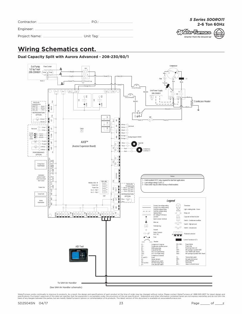
WaterFurnace works continually to improve its products. As a result, the design and specifi cations of each product at the time of order may be changed without notice. Please contact WaterFurnace at 1-888-929-2837 for latest design and specifi cations. Purchaser’s approval of this data set signifi es that the equipment is acceptable under the provisions of the job specifi cation. Statements and other information contained herein are not express warranties and do not form the basis of any bargain between the parties, but are merely WaterFurnace’s opinion or commendation of its products. The latest version of this document is available at www.waterfurnace.com.
Contractor: P.O.: Engineer:
Project Name: Unit Tag:
SD2504SN 04/17 23 Page _____ of ____z
5 Series 500RO112-6 Ton 60Hz
Wiring Schematics cont.
Compressor Common CT
GNDOUT5DC
123Red
T
T
TBrown
Brown
Black
Red
GNDOUT5DC
123
White
Capacitor CT
Blue TBlue
SCT
SUC
P
WhiteBlack
HW HW
CT
Blue
Blue
Red
Red
White
White
Black
Black
Orange
Orange
REFRIGERATION OPTION
REFRIGERATION OPTION
PERFORMANCEOPTION
White
White
Purple
Purple
Gray
Gray
White324
FLOW METER
NOT USED
Brown
Green
PRESSURE TRANSDUCER
PRESSURE TRANSDUCER
CT
AID Tool
SAH Air Handler
Pump Slave Input/Output
Future Use
Smart Grid
HomeAutomation
Not Used
Analog Output 0-10VDC
P8
MOTO
R P6
RS48
5 P7
ZONE P9
ABC
STEP
PER
ANA
ACC2
DHDI
V
NO
CO
M
K6
NO
CO
M
K5
C R L1 L1 L2 L2P1
2P1
0P5
P11
CR(-)(+) CR(-)(+) CR(-)(+)
P4P2
K1K2
K3
HA2
HA1
SGI
LOOP
VS D
ATA
VS P
UMP
PUMP
SLAV
EP3
V+CRTXRX +5
P14
LLT
P1LA
TFL
OWLW
TEW
T
CT2
43
CT2
43
CT1
21
CT1
21
StatusG
DISC
HP1
6
P17
P18
P15
(Aurora Expansion Board)AXB™
SW1
Modbus Add. IDFuture Use
12345
ONOFF
Future UseAcc 2 – Dip 1Acc 2 – Dip 2
Current Transducer (CT)
Thermistor
Light emitting diode - Green
Relay coil
Capacitor w/ bleed resistor
Switch - Condensate overflow
Switch - High pressure
Switch - Low pressure
Polarized connector
Factory Low voltage wiringFactory Line voltage wiringField low voltage wiringField line voltage wiringOptional blockDC Voltage PCB tracesJunctionQuick connect terminal
Wire nut
Field wire lug
Ground
Fuse
CC -CO -K5 -K6 -CR3 -CR4 -
F1 and F2 -
WCL -
HE -HP -
LP -
PB1, PB2 - PS -RV -SW1 -SW1 -SW2 -
TS -
Compressor ContactorCondensate overflow sensorDHW pump relayLoop pump relay
Fuses
Water Coil Limit Sensor
Heater elementHigh pressure switch
Low pressure switch
Power blocksPower stripReversing Valve coilDIP package 5 position AXBTEST MODE ABC BoardDIP package 8 position ABC Board
Thermal limit switch
Legend
Relay Contacts-N.O., N.C.
G
T
132P
L1
PSC Fan Speed RelayPSC Fan Power Relay
ER1 to ER4 - Aux heat stage relays
HWL - Hot water limit sensorSC - Start Contactor
Start RelaySR -
CS - Compressor Solenoid
Breaker
CS
+5C
CC
21
INOU
T+5
S
Not Used
Notes
3 – Flow center may be either factory or field installed. 2 – Low voltage wiring CLASS 2.1 – Field installed SPST relay required for duel fuel applications
Compressor
CCT2 T1
C
R
SBlue
G L1L2
Black
208-230/60/1Unit Power Supply
Black(2)
RedTan(16)
Black(1)
Cap
Violet(7)
Circuit Breaker
Circuit Breaker
5A
5A
5
2 4RP
Black(3)
FP
Red(11) Red(12)
Crankcase Heater
Black
Black
1
2
PB1
1
2
1
Ext Pump 1/2 hp Total 208-230/60/1 PumpPump Yellow(8)
Gray(9)G
GGreen(17) Ground LugNote 3
Flow Center
Violet (8)Brown(15)
Orange(14)
VARIABLE SPEED PUMP
LOW VOLTAGE NOT USED
Dual Capacity Split with Aurora Advanced - 208-230/60/1

WaterFurnace works continually to improve its products. As a result, the design and specifi cations of each product at the time of order may be changed without notice. Please contact WaterFurnace at 1-888-929-2837 for latest design and specifi cations. Purchaser’s approval of this data set signifi es that the equipment is acceptable under the provisions of the job specifi cation. Statements and other information contained herein are not express warranties and do not form the basis of any bargain between the parties, but are merely WaterFurnace’s opinion or commendation of its products. The latest version of this document is available at www.waterfurnace.com.
Contractor: P.O.: Engineer:
Project Name: Unit Tag:
SD2504SN 04/17 24 Page _____ of ____z
5 Series 500RO112-6 Ton 60Hz
Wiring Schematics cont.
RV
CC
HP
Black(10)
Black(09)
Blue(08)
Blue(07)
LP
TYellow
Yellow
FP1
Orange(02)
Orange(01)
RV
Black(15)
Violet(14)
Green(11)
UltraTech
RCP
CS
Blue
Blue
CFM
P13
P4
SW1
P5JW2
P9
LO
O/B
Y2WDH
P8 P7
RS485 NET RS485 NET
P6
RS485 EXP
P3
SW2
On
Future Use L Output Type
CC – Dual/SingleAcc – Dip 5Acc – Dip 4
RV – B/OFP2 – 15°F/30°FFP1 – 15°F/30°F
Com1LED5
Com2LED5
Test Mode
F1-3A
P1
C
PWM
12345678
ALMALGACC COMACC NOACC NC
RC
GY1
EH2CEH1CCOC R - +C R - +
Off
FaultLED1
R
StatusLED3
ConfigLED2
CC2 CC F C R F FG CC CCGCC2HI
CC2LO
CC2G REV REV FP1 FP1 FP2 FP2 LPS LPS HPS HPS
Aurora Base Control(ABC)
K1-RV Relay
K2-CC Relay
K3-CC2 Relay
K4-Fan RelayK5-Alarm Relay
K6-Acc Relay
F
R
C
CCGY1C
R
ESLS
P2
EH1
YG G
G
470 Ohm Resistor
CCT2 T1
Compressor
C
R
SBlue
GL1L2208-230/60/1
Unit Power Supply
Tan(6)
Cap
Run Winding
Active
Start
Common
IntelliStart
Black
Blue
PinkBlack
Red
CT
CT
IntelliStart OptionY1
Y2
O
R
C
L
C
R
Fossil Fuel Furnace
Thermostat
24 VAC
Common Common
24 VAC
Fault Signal
Reversing Valve
2nd Stage Compressor
1st Stage Compressor Y1
Y2
O
R
C
LO
Split
GG Fan
W
W
Auxiliary Heat Relay
Duel Fuel Wiring DiagramUsing Field Installed Relay
Note 1: Field installed SPST dual fuel relay (Required for dual fuel installation)
Auxiliary Heat RelayP2
P1
Auxiliary Heat Relay
ES
= chassis
Aurora LED Flash Codes
Status LED (LED3, Green)
Status LED (LED1, Green)Configuration LED (LED2, Yellow)Fault LED (LED3, Red)
Random Start Delay (Alternating Colors)Fast FlashFast FlashFast Flash
1 second on and 1 second off100 milliseconds on and 100 milliseconds off100 milliseconds on and 400 milliseconds off with a 2 second pause before repeating
Slow FlashFast FlashFlash Code
Normal ModeControl is Non-FunctionalTest ModeLockout ActiveDehumidification ModeFuture UseFuture UseLoad ShedESD
OFFON
Slow FlashFast Flash
Flash Code 2Flash Code 3
Flash Code 6
Flash Code 4Flash Code 5
Future Use Flash Code 7
Configuration LED (LED2, Yellow)No Software Overide OFFDIP Switch Overide Slow Flash
Fault LED (LED1, Red)Normal ModeInput Fault LockoutHigh Pressure LockoutLow Pressure LockoutFuture UseFreeze Detection – FP1ReservedCondensate Overflow LockoutOver/Under Voltage ShutdownFuture UseFuture UseFP1 and FP2 Sensor Error
Flash Code 1OFF
Flash Code 2Flash Code 3Flash Code 4Flash Code 5
Flash Code 8
Flash Code 6Flash Code 7
Flash Code 9Flash Code 10Flash Code 11
Dual Capacity Split with Aurora Advanced - 208-230/60/1 cont.

WaterFurnace works continually to improve its products. As a result, the design and specifi cations of each product at the time of order may be changed without notice. Please contact WaterFurnace at 1-888-929-2837 for latest design and specifi cations. Purchaser’s approval of this data set signifi es that the equipment is acceptable under the provisions of the job specifi cation. Statements and other information contained herein are not express warranties and do not form the basis of any bargain between the parties, but are merely WaterFurnace’s opinion or commendation of its products. The latest version of this document is available at www.waterfurnace.com.
Contractor: P.O.: Engineer:
Project Name: Unit Tag:
SD2504SN 04/17 25 Page _____ of ____z
5 Series 500RO112-6 Ton 60Hz
General Furnish and install WaterFurnace Water Source Heat
Pumps, as indicated on the plans. The geothermal
heating/cooling units shall be reverse cycle split system
configuration designed for use with DX heating and
cooling coils. Units shall be AHRI/ISO 13256-1 certified and listed by a nationally recognized safety-testing laboratory or agency, such as ETL Testing Laboratory. Each unit shall be computer run-tested at the factory with conditioned water and operation verified to catalog data. Each unit shall be mounted on a pallet and shipped in a corrugated box or stretch-wrapped. The units shall be designed to operate with entering liquid temperature between 20°F and 120°F
[-6.7°C and 48.9°C].
Casing and CabinetThe cabinet shall be fabricated from heavy-gauge galvanized steel and finished with corrosion-resistant powder coating. This corrosion protection system shall meet the stringent 1000 hour salt spray test per ASTM B117. The interior shall be insulated with 1/2-inch thick, multi-density, cleanable aluminum foil coated glass fiber with edges sealed or tucked under flanges. Standard cabinet panel insulation must meet NFPA 90A requirements, air erosion and mold growth limits of UL-181, stringent fungal resistance test per ASTM-C1071 and ASTM G21, and shall meet zero level bacteria growth per ASTM G22. Unit insulation must meet these stringent requirements or
unit(s) will not be accepted.
Refrigerant Circuit All units shall contain a sealed refrigerant circuit including a
hermetic motor-compressor, thermostatic expansion valve,
reversing valve, coaxial tube water-to-refrigerant heat
exchanger, compressor discharge muffler, accumulator, and
service ports.
Compressors shall be high-efficiency scroll single speed
or dual capacity type designed for heat pump duty and
mounted on rubber vibration isolators. Compressor motors
shall be single-phase PSC with overload protection.
The coaxial water-to-refrigerant heat exchanger shall be designed for low water pressure drop and constructed of a convoluted copper (cupronickel option) inner tube and a steel outer tube. Refrigerant to water heat exchangers shall be of copper inner water tube and steel refrigerant outer tube design, rated to withstand 600 psig (4135 kPa) working refrigerant pressure and 450 psig (3101 kPa) working water pressure. The thermostatic expansion valve shall provide proper superheat over the entire liquid temperature range with minimal “hunting.”
All units shall have the source coaxial tube refrigerant-to-water heat exchanger coated with ThermaShield. Refrigerant suction lines shall be insulated to prevent
condensation at low liquid temperatures.
ElectricalA control box shall be located within the unit compressor compartment and shall contain a 2 pole compressor contactor, circuit breakers for protecting loop pumps, terminal block for thermostat wiring, and solid-state controller for complete unit operation. Electromechanical operation WILL NOT be accepted. Units shall be name-plated for use with time delay fuses or HACR circuit breakers. Unit controls shall be 24 volt and provide heating or cooling as required by the remote thermostat/sensor. An Aurora, a microprocessor-based controller, interfaces with a multi-stage electronic thermostat to monitor and control unit operation shall be provided. The control shall provide operational sequencing, high and low pressure switch monitoring, freeze detection, lockout mode control, hot water and loop pump control, LED status and fault indicators, fault memory, field selectable options, and accessory output. The Lockout signal output shall have a pulsed option so that DDC systems can read specific lockout conditions from the control.
A detachable terminal block with screw terminals will be provided for field control wiring. All units shall have knockouts for entrance of low and line voltage wiring. The control box shall be harness plug wired for easy removal.
An optional Aurora Interface Diagnostic (AID) Tool shall communicate with the Aurora control allowing quick and easy access to setup, monitoring, and troubleshooting of any Aurora control. The device shall include the features of fault description and history, manual operation capability,
sensor readings, timings, and other diagnostic tools.
Optional IntelliStart® (compressor Soft Starter) shall be factory installed for use in applications that require low starting amps, reduced compressor start-up noise, off-grid, and improved start-up behavior. IntelliStart shall reduce normal starting current by 60% on 208/60/1 units.
PipingSupply and return water connections shall be 1 in. [25.4 mm] GeoLink swivel fittings, which provide a union and eliminate the need for pipe wrenches and sealants when making field connections. All water piping shall be insulated to prevent
condensation at low liquid temperatures.
Engineering Guide Specifi cations

WaterFurnace works continually to improve its products. As a result, the design and specifi cations of each product at the time of order may be changed without notice. Please contact WaterFurnace at 1-888-929-2837 for latest design and specifi cations. Purchaser’s approval of this data set signifi es that the equipment is acceptable under the provisions of the job specifi cation. Statements and other information contained herein are not express warranties and do not form the basis of any bargain between the parties, but are merely WaterFurnace’s opinion or commendation of its products. The latest version of this document is available at www.waterfurnace.com.
Contractor: P.O.: Engineer:
Project Name: Unit Tag:
SD2504SN 04/17 26 Page _____ of ____z
5 Series 500RO112-6 Ton 60Hz
Options and AccessoriesCupronickel Heat ExchangerAn optional cupronickel water-to-refrigerant heat
exchanger shall be provided.
Thermostat (field-installed)A multi-stage auto-changeover electronic digital thermostat shall be provided. The thermostat shall offer three heating and two cooling stages with precise temperature control. An OFF-HEAT-AUTO-COOL-EMERG system switch, OFF-AUTO blower switch, and indicating LEDs shall be provided. The thermostat shall display in °F
or °C. The thermostat shall be a traditional 24 VAC type.
Flow Center (field-installed)A self-contained module shall provide all liquid flow, fill and connection requirements for ground source closed loop systems up to 20 gpm. The pumps shall be wired to a power block located in the nearest unit. The heat pump units shall contain low voltage pump slaving control so that
two units may share one flow center.
Internally Mounted GeoLink Flow Center A self-contained module shall provide all liquid flow, fill and connection requirements for ground source closed loop systems up to 20 gpm. The pumps shall be wired to a
power block located in the nearest unit.
Engineering Guide Specifi cations cont.

WaterFurnace works continually to improve its products. As a result, the design and specifi cations of each product at the time of order may be changed without notice. Please contact WaterFurnace at 1-888-929-2837 for latest design and specifi cations. Purchaser’s approval of this data set signifi es that the equipment is acceptable under the provisions of the job specifi cation. Statements and other information contained herein are not express warranties and do not form the basis of any bargain between the parties, but are merely WaterFurnace’s opinion or commendation of its products. The latest version of this document is available at www.waterfurnace.com.
Contractor: P.O.: Engineer:
Project Name: Unit Tag:
SD2504SN 04/17 27 Page _____ of ____z
5 Series 500RO112-6 Ton 60Hz
Pages: Description: Date: By:
All First Published 30 Oct 2013 DS
4 Updated Nomenclature to show FC2-GL Flow Center Option 16 June 2014 MA
Misc. Updated for new Air Handler 10 Mar 2017 JM
Revision Guide