SD-Access Segmentation Design Guide - cisco.com · Intent-based networking and segmentation ... to...
37
CISCO VALIDATED DESIGN SD-Access Segmentation Design Guide May 2018
Transcript of SD-Access Segmentation Design Guide - cisco.com · Intent-based networking and segmentation ... to...

s CISCO VALIDATED DESIGN
SD-Access Segmentation Design Guide
May 2018

Table of Contents
Cisco Validated Design
Table of ContentsIntroduction .................................................................................................................................... 1
Intent-based networking and segmentation ..................................................................................... 2
Understanding virtual networks and SGTs in SD-Access .................................................................................................4
Enforcement of traffic destined external to the fabric ......................................................................................................9
Defining network segments ........................................................................................................... 16
Virtual networks or scalable group tags ......................................................................................................................... 17
Use cases...................................................................................................................................... 21
University ....................................................................................................................................................................... 21
Manufacturing ............................................................................................................................................................... 22
Healthcare ..................................................................................................................................................................... 24
PCI and retail ................................................................................................................................................................. 26
Electric power ............................................................................................................................................................... 26
Appendix A: Network segmentation overview: A brief history ........................................................ 28
VLANs and private VLANs ............................................................................................................................................. 28
Virtual routing and forwarding instances ........................................................................................................................ 29
Cisco TrustSec—Software-defined segmentation.......................................................................................................... 31
Appendix B: References ................................................................................................................ 34

page 1Cisco Validated Design
Introduction
Introduction An ever-growing number of cyberattacks are launched daily against organizations of all types, carried out by individuals, organized syndicates, and state-sponsored hackers. Whether for purposes of financial gain through acquiring credit card data, extortion through ransomware, access to personal data for identity theft, or disruption of services, these attacks are continually growing in frequency and sophistication. Furthermore, with the ever-growing availability of open-source codebases and tools, these attacks no longer require a high level of skill, enabling them to be launched by less sophisticated threat actors.
Organizations struggle to identify not only those technologies and products that will protect them but the budget necessary to acquire, implement, and operate them. Products such as Cisco Firepower® Next-Generation Firewall and Intrusion Prevention System, Cisco® Web Security Appliance (WSA), Cisco Advanced Malware Protection, and Cisco Stealthwatch® providing network visibility, and Cisco Identity Services Engine providing policy and secured network access for authorized users, guests, and IoT devices are all effective in providing a “defense-in-depth” strategy to protect an organization. Once adopted, the focus shifts to defining an implementation strategy that will protect an organization’s critical assets and data by enforcing authorized access to the network while also monitoring communications for anomalous behavior from endpoint to data center.
Another very effective strategy to consider, underlying all other security products, is the use of network segmentation to reduce the scope of an attack. Network segmentation can be described as the process of breaking down or splitting a single large network, with a single routing table, into any number of smaller networks or zones either virtually or logically. With a segmented network, and security controls to enforce policies in and out of the segment, you
• Provide isolation between segments, supporting regulatory compliance
• Minimize the attack surface, limiting it to only one segment, thereby restricting the east/west propagation of malware
• Introduce enforcement points between segments where stateful packet inspection can be implemented
• Provide an environment where further micro-segmentation is possible
The purpose of this document is to familiarize you with Cisco Software-Defined Access and its unparalleled capabilities in implementing network segmentation in your network. Its intent is to assist you in better understanding the architecture and further assist in strategizing the approach to be taken.
If you are unfamiliar with network segmentation, before proceeding you may want to read Appendix A, which offers a brief history of network segmentation. We also recommend that you read the TrustSec User-to-Data-Center Access Control Using TrustSec Design Guide in order to understand the Cisco TrustSec® software-defined segmentation architecture. It is very important that you have an understanding of the Cisco TrustSec solution because it is the basis for Scalable Group Tags (SGTs) and their use in group-based access control policies found within SD-Access. An overview of TrustSec can be found in Appendix A as well.

page 2Cisco Validated Design
Intent-based networking and segmentation
Intent-based networking and segmentationOriginally, network segmentation was aligned to a strategy for improving network stability and performance. Over time, it has evolved to reflect a security strategy in which the network is segmented or compartmentalized to enforce a policy by enabling controls within and between segments.Today, while VLANs and private VLANs still provide rudimentary Layer 2 segmentation of Layer 3 IP subnets for some organizations, many others have chosen to use VRFs or software-defined segmentation via Cisco TrustSec as the primary means of segmenting a network. VRFs provide complete isolation of routing and switching environments, making VRF a common network segmentation technology for a substantial number of organizations using VRF-Lite through either 802.1Q trunks or GRE or, in many cases, even MPLS as the underlying transport. Aside from VRFs, however, an increasing number of customers are using Cisco TrustSec to provide logical, group-based segmentation without the need to support data plane isolation along with the routing/control plane considerations inherent to VRFs. As will be discussed in the section “Defining network segments” later in this document, both approaches offer their own unique benefits, and some customers have decided to implement both technologies. VRFs and Cisco TrustSec software-defined segmentation will continue to be, both now and in the foreseeable future, extremely effective methods for segmenting the network and, through this segmentation, whether virtual or logical, extending a security policy. A network segmentation strategy developed to enforce security policy in support of an organization’s business requirements is typically not limited to a single location. It could be needed across a campus consisting of multiple buildings with thousands of devices or across remote sites such as stores or branches, each with a handful of devices. A given network segment, and the policies it represents, may be extended anywhere within an organization where one of the business-relevant applications or functions reside. Historically, when implementing VRFs or Cisco TrustSec, manual configuration of the network infrastructure is unavoidable. Whether extending VRFs through VRF-Lite or MPLS or enabling the propagation of the Cisco TrustSec SGTs, configuration must be completed manually, often on a hop-by-hop basis. With the introduction of Cisco Software-Defined Access (SD-Access) and, more broadly Cisco’s Digital Network Architecture (DNA), the means by which network segmentation can be implemented are once again evolving. To quote the “Cisco Intent-Based Networking” white paper:Intent-based networking solutions enable conventional practices that require the alignment of manually derived individual network-element configurations to be replaced by controller-led and policy-based abstractions that easily enable operators to express intent (desired outcome) and subsequently validate that the network is doing what they asked of it.
Reader tip
For more information about Cisco’s intent-based networking architecture, visit https://www.cisco.com/c/en/us/solutions/intent-based-networking.html
For the Cisco IBN white paper, visit https://www.cisco.com/c/dam/en/us/solutions/collateral/enterprise-networks/digital-network-architecture/nb-09-intent-networking-wp-cte-en.pdf?oid=wpren006178

page 3Cisco Validated Design
Intent-based networking and segmentation
One of the key benefits realized as a result of Cisco Intent-Based Networking (IBN) and enabling technologies such as SD-Access is the ability to ensure that a security policy for compliance exists throughout the organization. The scope of an IBN thus extends from the data center and cloud environments all the way to the campus and remote locations, and encompasses even remote access to the network, whether for employees, contractors, or vendors. Those controllers, which provide the automation and controls that make up the IBN, reduce risk by assuring that security policies are being applied consistently across the network, and help ensure that policies are compliant with business requirements. They capture and translate business intent into network policies and activate them across the infrastructure.A similar example in the data center, Cisco Application Centric Infrastructure (Cisco ACI™), powered by the Cisco Application Policy Infrastructure Controller (APIC), offers an architecture that can translate business requirements into secured zones or enclaves. With Cisco ACI deployed, contracts or policies can be created that allow only specific communications between tiered applications, as well as access to external resources, whether applications or users, while blocking all other unauthorized access. Within the Cisco ACI policy model, both VRFs as well as group-based Endpoint Groups (EPGs)—similar in many ways to SGTs, even to the extent that they can be translated—are used to provide segmentation. Contracts, defined through the use of EPG security policies and application network profiles, are applied to controlling communications, both into and out of the data centers as well as within it between applications and data repositories.
Reader tip
For more information regarding the APIC policy model, refer to the white paper at https://www.cisco.com/c/en/us/solutions/collateral/data-center-virtualization/application-centric-infrastructure/white-paper-c11-731310.html
Within the SD-Access architecture, Cisco DNA Center™ and Cisco ISE work in unison to provide the automation for planning, configuration, segmentation, identity, and policy services. Cisco ISE is responsible for device profiling, identity services, and policy services, dynamically exchanging information with DNA Center. DNA Center consists of the automation and assurance components that work in unison to form a closed-loop automation system, enabling the configuration, monitoring, and reporting required to realize the full extent of the Cisco IBN in campus environments.When DNA Center is implemented, ISE is still deployed as a separate appliance providing identity and policy services for the SD-Access campus fabric. When creating SGTs through the DNA-C user interface, the ISE user interface is cross-launched and the task completed there; ISE maintains all of the scalable group information later used in DNA-C for policy creation. Although the policies and corresponding contracts are created at DNA-C, both are communicated back to ISE through representational state transfer application programming interface (REST API) calls. ISE then serves as the single point of reference for SGTs, policies, and contracts (SGACLs), which are then dynamically distributed to the network infrastructure.Segmentation within SD-Access is enabled through the combined use of both Virtual Networks (VN), which are synonymous with VRFs, and Cisco TrustSec Scalable Group Tags (SGTs). Whereas segmentation can be accomplished through the use of intent-driven or purpose-built virtual networks alone, Cisco TrustSec SGTs provide logical segmentation based on group membership. Cisco TrustSec provides an additional layer of granularity, allowing you to use multiple SGTs within a single VN providing micro-segmentation within the VN.
Reader tip
For more information on SD-Access, refer to https://www.cisco.com/c/en/us/solutions/enterprise-networks/software-defined-access/index.html as well as the Cisco Validated Design SD-Access Design Guide at https://www.cisco.com/c/en/us/solutions/design-zone.html.
page 4Cisco Validated Design
Intent-based networking and segmentation
Reader tip
Prior to SD-Access, the acronym SGT referred to “security group tag.” It has since been changed to “scalable group tag,” as in the future SGTs may be used for other purposes. Quality of Service (QoS) and policy-based routing are two such examples, having been implemented in TrustSec prior to Software-Defined Access (SD-Access).
Although this design guide focuses specifically on segmentation and policy constructs in SD-Access, it is important to understand how SD-Access and other technologies, such as SD-WAN, interact with data centers based on Cisco ACI, as well as with infrastructure that has implemented either Cisco TrustSec or VRFs. The importance of understanding how these technologies intersect and how policies are translated between environments cannot be overlooked as organizations begin the process of migrating to a full IBN model. Existing segmentation strategies, whether Cisco ACI, VRFs, or Cisco TrustSec, will influence decisions regarding how virtual networks at the macro-segmentation level and scalable groups at a micro-segmentation level should be organized and populated within an SD-Access fabric.
Understanding virtual networks and SGTs in SD-Access
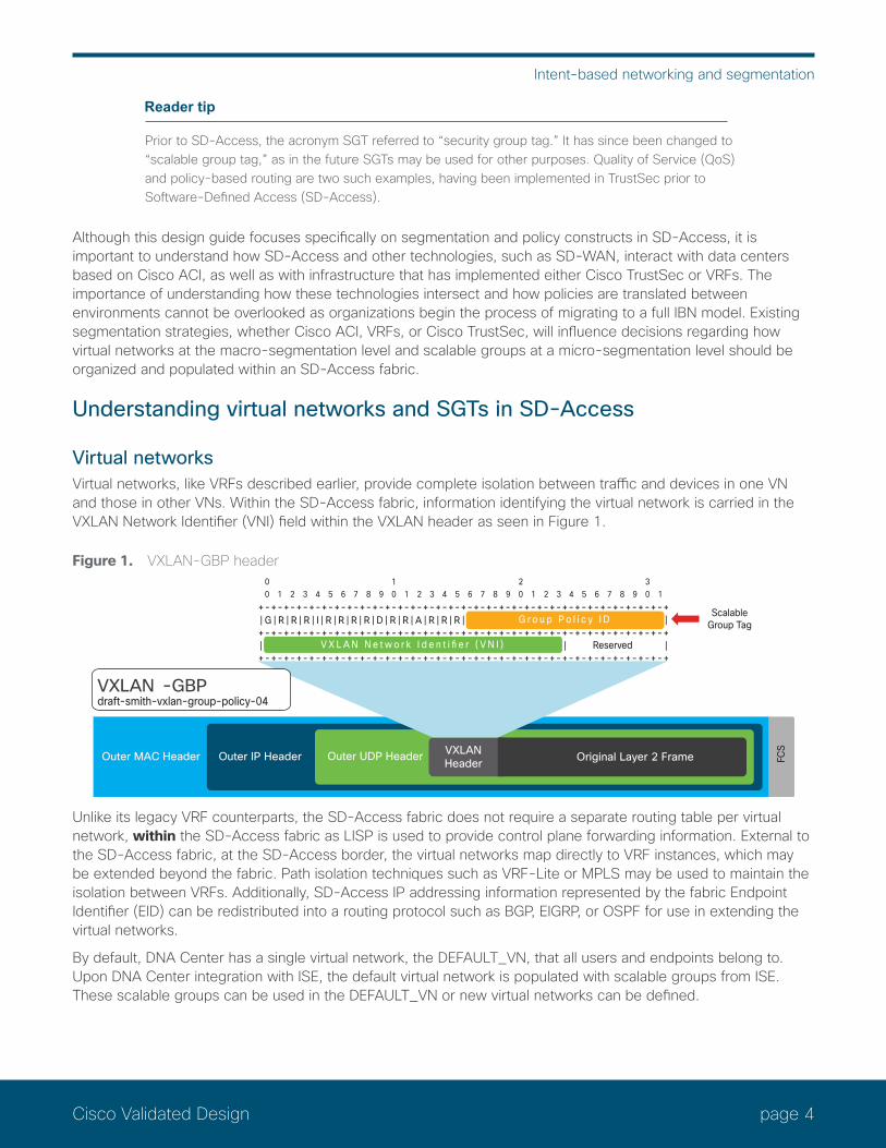
Virtual networksVirtual networks, like VRFs described earlier, provide complete isolation between traffic and devices in one VN and those in other VNs. Within the SD-Access fabric, information identifying the virtual network is carried in the VXLAN Network Identifier (VNI) field within the VXLAN header as seen in Figure 1.
Figure 1. VXLAN-GBP header
Reserved
0 1 2 3 4 5 6 7 8 9 0 1 2 3 4 5 6 7 8 9 0 1 2 3 4 5 6 7 8 9 0 10 1 2 3
+-+-+-+-+-+-+-+-+-+-+-+-+-+-+-+-+-+-+-+-+-+-+-+-+-+-+-+-+-+-+-+-+
+-+-+-+-+-+-+-+-+-+-+-+-+-+-+-+-+-+-+-+-+-+-+-+-+-+-+-+-+-+-+-+-+
+-+-+-+-+-+-+-+-+-+-+-+-+-+-+-+-+-+-+-+-+-+-+-+-+-+-+-+-+-+-+-+-+| G | R | R | R | I | R | R | R | R | D | R | R | A | R | R | R |
ScalableGroup Tag
V X L A N N e t w o r k I d e n t i fi e r ( V N I )
G r o u p P o l i c y I D
Outer MAC Header Outer IP Header Outer UDP Header VXLANHeader Original Layer 2 Frame
VXLAN -GBPdraft-smith-vxlan-group-policy-04
FCS
Unlike its legacy VRF counterparts, the SD-Access fabric does not require a separate routing table per virtual network, within the SD-Access fabric as LISP is used to provide control plane forwarding information. External to the SD-Access fabric, at the SD-Access border, the virtual networks map directly to VRF instances, which may be extended beyond the fabric. Path isolation techniques such as VRF-Lite or MPLS may be used to maintain the isolation between VRFs. Additionally, SD-Access IP addressing information represented by the fabric Endpoint Identifier (EID) can be redistributed into a routing protocol such as BGP, EIGRP, or OSPF for use in extending the virtual networks.
By default, DNA Center has a single virtual network, the DEFAULT_VN, that all users and endpoints belong to. Upon DNA Center integration with ISE, the default virtual network is populated with scalable groups from ISE. These scalable groups can be used in the DEFAULT_VN or new virtual networks can be defined.
page 5Cisco Validated Design
Intent-based networking and segmentation
Because VRFs external to the fabric isolate communications between them by using separate routing tables per VRF, it is necessary to forward traffic to an external network device to enable these communications if desired. A firewall, Layer 3 switch, or router can then be used to leak routing information, maintained in each VRF, thus enabling communication between virtual networks while also providing a control point to enforce established security policies. As discussed earlier, these network devices are commonly referred to as “fusion” firewalls or routers. Today these fusion routers and firewalls must be external to the fabric.
Scalable group tagsAs discussed previously, SGTs are represented by a 16-bit group identifier that is associated with the scalable groups, the membership of which is based on business roles or functions. By default, there are a number of predefined scalable groups along with an associated hexadecimal tag ID. You also can define new scalable groups along with a tag ID of your choosing. If we think of user roles in a healthcare environment as an example, we could organize users into doctors, nurses, imaging technicians, pharmacy, patients, and guests. Likewise, we could assign unique SGTs to different devices, such as IP cameras, HVAC control, keypads/swipes, and digital signage. Little has changed relative to how SGTs are used within SD-Access when compared to Cisco TrustSec in today’s non-fabric networks. SGTs continue to provide a means by which devices or users can be logically segmented from one another. Future development will likely change what information or intent can be derived from an SGT.
The primary difference in SGT creation and use within SD-Access is that the process of defining SGTs is started at DNA Center and then used within the virtual networks established by an organization. As the global routing table is reserved for use in the underlay of the SD-Access fabric, the SGTs and the logical segmentation they represent, will be created in the DEFAULT_VN for use there or for assignment to other user-created virtual networks. Today, a scalable group can be used only in a single virtual network.
Propagation of the SGT in an SD-Access network is no longer performed on a hop-by-hop basis as with TrustSec inline tagging, but is carried within the VXLAN header, as shown earlier in Figure 1. As can be seen in the figure, the SGT and VNI are both maintained in the VXLAN header for communication between VXLAN tunnel endpoints in the SD-Access fabric.
As we have discussed, segmentation within SD-Access takes place at both a macro and a micro level through virtual networks and SGTs, respectively. Virtual networks are completely isolated from one another within the SD-Access fabric, providing macro-segmentation between endpoints within one VN from other VNs. By default, all endpoints within a virtual network can communicate with each other. Because each virtual network has its own routing instance, an external, non-fabric device known as a fusion router or firewall is required to provide the inter-VRF forwarding necessary for communications between the VNs. It is at this fusion device that a policy can be implemented based on a standard IP-based ACL, scalable group tags, or a combination of both. You can also enforce policies that have been defined at DNA Center for traffic within virtual networks based on the SGTs that endpoints are assigned. These policies, or SGACLs, may be as simple as permit/deny or may be based on Layer 4 access control entries explicitly permitting/denying specific TCP/UDP ports and are called Contracts in DNA Center. The policies and associated contracts are configured in DNA Center and then communicated through the REST API to ISE. ISE then updates the edge nodes with only those policies for SGTs associated with the attached devices. Enforcement occurs upon egress where the destination is attached.
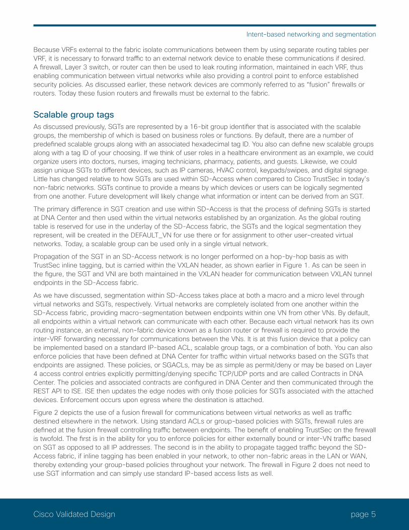
Figure 2 depicts the use of a fusion firewall for communications between virtual networks as well as traffic destined elsewhere in the network. Using standard ACLs or group-based policies with SGTs, firewall rules are defined at the fusion firewall controlling traffic between endpoints. The benefit of enabling TrustSec on the firewall is twofold. The first is in the ability for you to enforce policies for either externally bound or inter-VN traffic based on SGT as opposed to all IP addresses. The second is in the ability to propagate tagged traffic beyond the SD-Access fabric, if inline tagging has been enabled in your network, to other non-fabric areas in the LAN or WAN, thereby extending your group-based policies throughout your network. The firewall in Figure 2 does not need to use SGT information and can simply use standard IP-based access lists as well.

page 6Cisco Validated Design
Intent-based networking and segmentation
Reader tip
The fusion firewall(s) as discussed in this document is considered to be Layer 3 adjacent to the SD-Access border node as well as any external infrastructure.
Firewalls that use SGTs in the rules are called Scalable Group Firewalls (SGFWs). SGFWs receive only the names and scalable group tag value from ISE; they do not receive the actual policies/rules. Unlike switches, where SGACLs are configured at DNA Center and deployed by ISE, SGT-based rule definition is performed locally at the SGFW through either the CLI or other management tool.
Reader tip
For further information regarding SGFW configuration, refer to Access Control Using Security Group Firewall.
Figure 2. Policy enforcement with a fusion firewall
SD-AccessDNA-C
pxGrid
FusionFirewall
BorderNode
ISE
SGT info only
Default VN
Campus VN
Employee
EM
Faculty
FA
Student
ST
Printer
PR
PR
Building VN
Contractor
COHVAC
HVIP Camera
IPPhysicalSecurity
PH
CO
Policy createdat FW basedon SGT
Enterprise Coreor Data Center
In Figure 2, traffic sourced from the Building VN and destined to either the Campus VN or external to the fabric, can either be forwarded or dropped based on the policy implemented on the firewall based on scalable groups.
When using firewall rules based on scalable groups and IP addresses or network objects, there are no additional considerations other than assuring that there are dedicated interfaces or sub-interfaces for each VN. The major drawback to the use of IP addresses in the firewall rules, however, is that if the endpoint addressing changes, the firewall rules must be updated to reflect these new addresses.
page 7Cisco Validated Design
Intent-based networking and segmentation
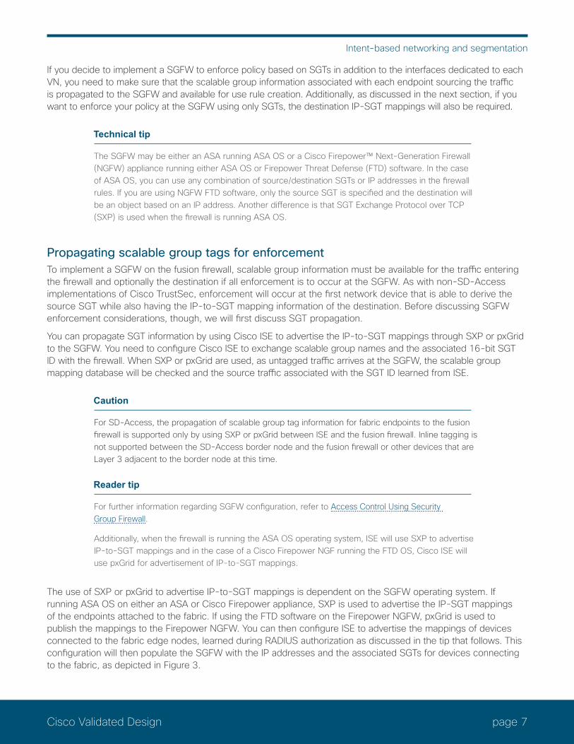
If you decide to implement a SGFW to enforce policy based on SGTs in addition to the interfaces dedicated to each VN, you need to make sure that the scalable group information associated with each endpoint sourcing the traffic is propagated to the SGFW and available for use rule creation. Additionally, as discussed in the next section, if you want to enforce your policy at the SGFW using only SGTs, the destination IP-SGT mappings will also be required.
Technical tip
The SGFW may be either an ASA running ASA OS or a Cisco Firepower™ Next-Generation Firewall (NGFW) appliance running either ASA OS or Firepower Threat Defense (FTD) software. In the case of ASA OS, you can use any combination of source/destination SGTs or IP addresses in the firewall rules. If you are using NGFW FTD software, only the source SGT is specified and the destination will be an object based on an IP address. Another difference is that SGT Exchange Protocol over TCP (SXP) is used when the firewall is running ASA OS.
Propagating scalable group tags for enforcementTo implement a SGFW on the fusion firewall, scalable group information must be available for the traffic entering the firewall and optionally the destination if all enforcement is to occur at the SGFW. As with non-SD-Access implementations of Cisco TrustSec, enforcement will occur at the first network device that is able to derive the source SGT while also having the IP-to-SGT mapping information of the destination. Before discussing SGFW enforcement considerations, though, we will first discuss SGT propagation.
You can propagate SGT information by using Cisco ISE to advertise the IP-to-SGT mappings through SXP or pxGrid to the SGFW. You need to configure Cisco ISE to exchange scalable group names and the associated 16-bit SGT ID with the firewall. When SXP or pxGrid are used, as untagged traffic arrives at the SGFW, the scalable group mapping database will be checked and the source traffic associated with the SGT ID learned from ISE.
Caution
For SD-Access, the propagation of scalable group tag information for fabric endpoints to the fusion firewall is supported only by using SXP or pxGrid between ISE and the fusion firewall. Inline tagging is not supported between the SD-Access border node and the fusion firewall or other devices that are Layer 3 adjacent to the border node at this time.
Reader tip
For further information regarding SGFW configuration, refer to Access Control Using Security Group Firewall.
Additionally, when the firewall is running the ASA OS operating system, ISE will use SXP to advertise IP-to-SGT mappings and in the case of a Cisco Firepower NGF running the FTD OS, Cisco ISE will use pxGrid for advertisement of IP-to-SGT mappings.
The use of SXP or pxGrid to advertise IP-to-SGT mappings is dependent on the SGFW operating system. If running ASA OS on either an ASA or Cisco Firepower appliance, SXP is used to advertise the IP-SGT mappings of the endpoints attached to the fabric. If using the FTD software on the Firepower NGFW, pxGrid is used to publish the mappings to the Firepower NGFW. You can then configure ISE to advertise the mappings of devices connected to the fabric edge nodes, learned during RADIUS authorization as discussed in the tip that follows. This configuration will then populate the SGFW with the IP addresses and the associated SGTs for devices connecting to the fabric, as depicted in Figure 3.
page 8Cisco Validated Design
Intent-based networking and segmentation
Reader tip
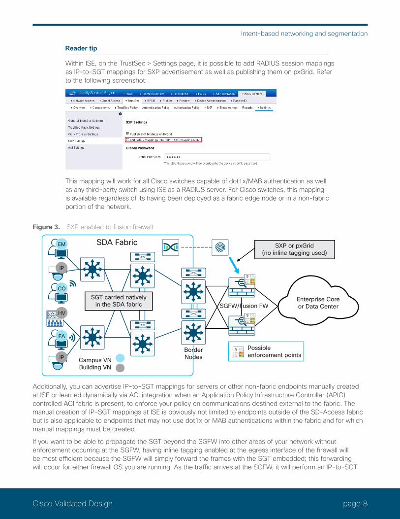
Within ISE, on the TrustSec > Settings page, it is possible to add RADIUS session mappings as IP-to-SGT mappings for SXP advertisement as well as publishing them on pxGrid. Refer to the following screenshot:
This mapping will work for all Cisco switches capable of dot1x/MAB authentication as well as any third-party switch using ISE as a RADIUS server. For Cisco switches, this mapping is available regardless of its having been deployed as a fabric edge node or in a non-fabric portion of the network.
Figure 3. SXP enabled to fusion firewall
Enterprise Coreor Data Center
BorderNodes
Possibleenforcement points
SXP or pxGrid(no inline tagging used)
SGT carried nativelyin the SDA fabric
Campus VNBuilding VN
SDA Fabric
FA
IP
CO
EM
HV
IP
SGFW/Fusion FW
Additionally, you can advertise IP-to-SGT mappings for servers or other non-fabric endpoints manually created at ISE or learned dynamically via ACI integration when an Application Policy Infrastructure Controller (APIC) controlled ACI fabric is present, to enforce your policy on communications destined external to the fabric. The manual creation of IP-SGT mappings at ISE is obviously not limited to endpoints outside of the SD-Access fabric but is also applicable to endpoints that may not use dot1x or MAB authentications within the fabric and for which manual mappings must be created.
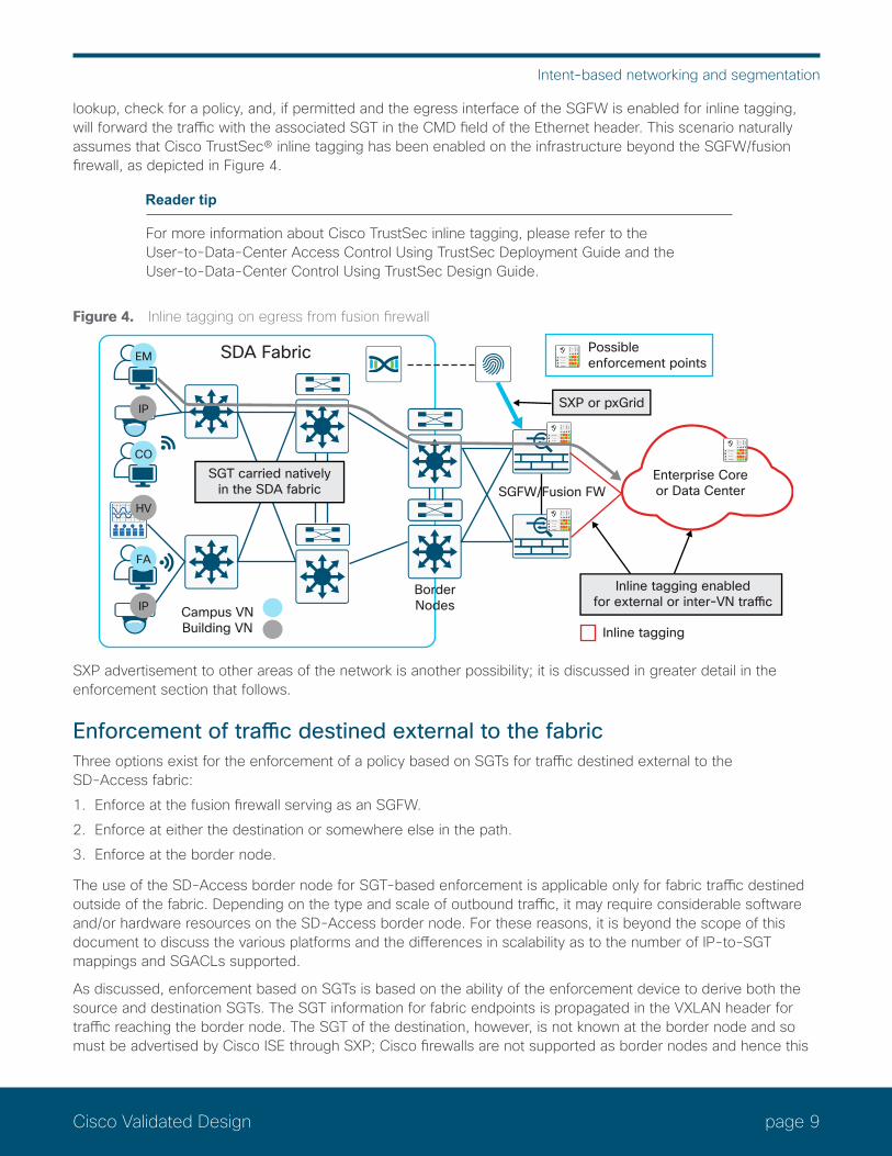
If you want to be able to propagate the SGT beyond the SGFW into other areas of your network without enforcement occurring at the SGFW, having inline tagging enabled at the egress interface of the firewall will be most efficient because the SGFW will simply forward the frames with the SGT embedded; this forwarding will occur for either firewall OS you are running. As the traffic arrives at the SGFW, it will perform an IP-to-SGT
page 9Cisco Validated Design
Intent-based networking and segmentation
lookup, check for a policy, and, if permitted and the egress interface of the SGFW is enabled for inline tagging, will forward the traffic with the associated SGT in the CMD field of the Ethernet header. This scenario naturally assumes that Cisco TrustSec® inline tagging has been enabled on the infrastructure beyond the SGFW/fusion firewall, as depicted in Figure 4.
Reader tip
For more information about Cisco TrustSec inline tagging, please refer to the User-to-Data-Center Access Control Using TrustSec Deployment Guide and the User-to-Data-Center Control Using TrustSec Design Guide.
Figure 4. Inline tagging on egress from fusion firewall
Enterprise Coreor Data Center
BorderNodes
Possibleenforcement points
Inline tagging enabledfor external or inter-VN traffic
Inline taggingCampus VNBuilding VN
SDA Fabric
FA
IP
CO
EM
HV
IP
SXP or pxGrid
SGFW/Fusion FWSGT carried natively
in the SDA fabric
SXP advertisement to other areas of the network is another possibility; it is discussed in greater detail in the enforcement section that follows.
Enforcement of traffic destined external to the fabricThree options exist for the enforcement of a policy based on SGTs for traffic destined external to the SD-Access fabric:1. Enforce at the fusion firewall serving as an SGFW.2. Enforce at either the destination or somewhere else in the path.3. Enforce at the border node.
The use of the SD-Access border node for SGT-based enforcement is applicable only for fabric traffic destined outside of the fabric. Depending on the type and scale of outbound traffic, it may require considerable software and/or hardware resources on the SD-Access border node. For these reasons, it is beyond the scope of this document to discuss the various platforms and the differences in scalability as to the number of IP-to-SGT mappings and SGACLs supported.
As discussed, enforcement based on SGTs is based on the ability of the enforcement device to derive both the source and destination SGTs. The SGT information for fabric endpoints is propagated in the VXLAN header for traffic reaching the border node. The SGT of the destination, however, is not known at the border node and so must be advertised by Cisco ISE through SXP; Cisco firewalls are not supported as border nodes and hence this
page 10Cisco Validated Design
Intent-based networking and segmentation
discussion is applicable only to Cisco routers and switches that are supported. Several points must be considered when enabling SXP learning of IP-SGT mappings at a network device such as a router or a switch:
• When a network device is defined at ISE for TrustSec policy enforcement, as the network device learns mapping information for an SGT, it will communicate with ISE to get the policies associated with that SGT as a destination. The SGACLs downloaded, in the case of a router or switch, will consume memory or TCAM, respectively. Numerous SGTs with their associated policies may lead to heavy memory usage in routers and TCAM exhaustion in switches. Ultimately, some SGACLs may not be installed.
• Network devices have well-defined limits as to the number of IP-to-SGT mappings they can store. These mappings will consume memory as the numbers of mappings increase. If the supported numbers are exceeded, mappings will not be installed in memory and as a result, policies specific to those mappings will not be enforced.
In lieu of these considerations, it is beyond the scope of this document to discuss the various platforms supported as border nodes and the differences in scalability as to the number of IP-to-SGT mappings and SGACLs supported.
Reader tip
For more information regarding policy enforcement on an SD-Access border node, please refer to Enforcing Policy on an SD-Access Border Node.
For more information about platform scalability regarding the number of IP-to-SGT mappings and SGACLs, refer to the TrustSec System Bulletins.
Option 1: Enforcement at fusion firewall serving as SGFWThe first option allows you to enforce group-based policies for all traffic leaving the SD-Access fabric at the fusion SGFW. There is no need to propagate the SGT of the fabric endpoints beyond the SGFW. With the first option, as discussed, you will have ISE advertise the IP-to-SGT mappings of the authenticated fabric endpoints to the SGFW. You will then need to decide whether the policies at the SGFW will use scalable group tags for the destination or IP addresses.
Depending on whether you are using ASA OS on the fusion firewall or FTD, you have different options for identifying the destination in the rules. With ASA OS, remember that any combination of SGTs or IP addresses can be used regardless of source and destination. Will need to be updated when FTD supports destination SGT.
If the policies you want to create consist of a source SGT and a destination IP address at the SGFW, regardless of operating system, and propagation of source SGT information is established through SXP or pxGrid between ISE and the SGFW, you will be able to proceed with rule creation and enforcement.
If you are running ASA OS on your SGFW and you decide that you want to use SGT information for both source and destination in your rules, whether external or in another virtual network, you will need to advertise the IP-to-SGT mapping information for these destinations to the SGFW with SXP. Remember the basic rule that enforcement based on SGT will occur at the first network device that has the IP-to-SGT mapping for the destination.
Reader tip
Concerns over IP-to-SGT scaling and SGT-based enforcement at a Cisco firewall regardless of operating system running are virtually nonexistent. Most current models of Cisco ASA firewalls and all FTD-based Firepower appliances typically scale to between 750,000 and 2 million IP-to-SGT mappings. Rules based on SGTs actually can consume far less memory than comparable rules based on IP addresses and/or network objects. For more information about platform scalability regarding the number of IP-to-SGT mappings, refer to the TrustSec System Bulletins.
page 11Cisco Validated Design
Intent-based networking and segmentation
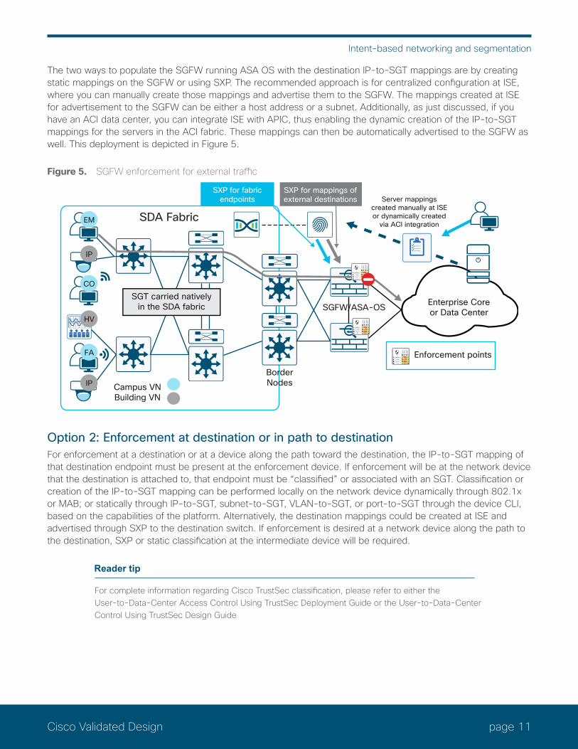
The two ways to populate the SGFW running ASA OS with the destination IP-to-SGT mappings are by creating static mappings on the SGFW or using SXP. The recommended approach is for centralized configuration at ISE, where you can manually create those mappings and advertise them to the SGFW. The mappings created at ISE for advertisement to the SGFW can be either a host address or a subnet. Additionally, as just discussed, if you have an ACI data center, you can integrate ISE with APIC, thus enabling the dynamic creation of the IP-to-SGT mappings for the servers in the ACI fabric. These mappings can then be automatically advertised to the SGFW as well. This deployment is depicted in Figure 5.
Figure 5. SGFW enforcement for external traffic
Enterprise Coreor Data Center
Server mappingscreated manually at ISEor dynamically created
via ACI integration
BorderNodes
SGFW/ASA-OS
Enforcement points
SGT carried nativelyin the SDA fabric
Campus VNBuilding VN
SDA Fabric
FA
IP
CO
EM
HV
IP
SXP for fabricendpoints
SXP for mappings ofexternal destinations
Option 2: Enforcement at destination or in path to destinationFor enforcement at a destination or at a device along the path toward the destination, the IP-to-SGT mapping of that destination endpoint must be present at the enforcement device. If enforcement will be at the network device that the destination is attached to, that endpoint must be “classified” or associated with an SGT. Classification or creation of the IP-to-SGT mapping can be performed locally on the network device dynamically through 802.1x or MAB; or statically through IP-to-SGT, subnet-to-SGT, VLAN-to-SGT, or port-to-SGT through the device CLI, based on the capabilities of the platform. Alternatively, the destination mappings could be created at ISE and advertised through SXP to the destination switch. If enforcement is desired at a network device along the path to the destination, SXP or static classification at the intermediate device will be required.
Reader tip
For complete information regarding Cisco TrustSec classification, please refer to either the User-to-Data-Center Access Control Using TrustSec Deployment Guide or the User-to-Data-Center Control Using TrustSec Design Guide
page 12Cisco Validated Design
Intent-based networking and segmentation
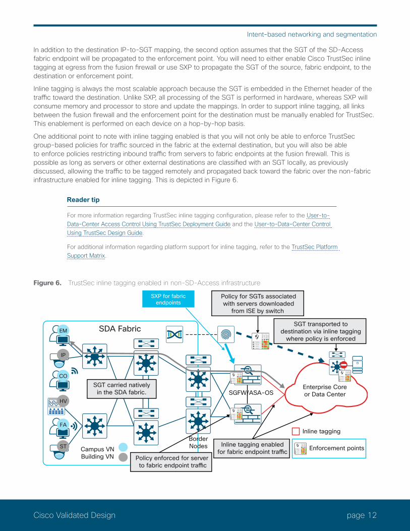
In addition to the destination IP-to-SGT mapping, the second option assumes that the SGT of the SD-Access fabric endpoint will be propagated to the enforcement point. You will need to either enable Cisco TrustSec inline tagging at egress from the fusion firewall or use SXP to propagate the SGT of the source, fabric endpoint, to the destination or enforcement point.
Inline tagging is always the most scalable approach because the SGT is embedded in the Ethernet header of the traffic toward the destination. Unlike SXP, all processing of the SGT is performed in hardware, whereas SXP will consume memory and processor to store and update the mappings. In order to support inline tagging, all links between the fusion firewall and the enforcement point for the destination must be manually enabled for TrustSec. This enablement is performed on each device on a hop-by-hop basis.
One additional point to note with inline tagging enabled is that you will not only be able to enforce TrustSec group-based policies for traffic sourced in the fabric at the external destination, but you will also be able to enforce policies restricting inbound traffic from servers to fabric endpoints at the fusion firewall. This is possible as long as servers or other external destinations are classified with an SGT locally, as previously discussed, allowing the traffic to be tagged remotely and propagated back toward the fabric over the non-fabric infrastructure enabled for inline tagging. This is depicted in Figure 6.
Reader tip
For more information regarding TrustSec inline tagging configuration, please refer to the User-to-Data-Center Access Control Using TrustSec Deployment Guide and the User-to-Data-Center Control Using TrustSec Design Guide.
For additional information regarding platform support for inline tagging, refer to the TrustSec Platform Support Matrix.
Figure 6. TrustSec inline tagging enabled in non-SD-Access infrastructure
Enterprise Coreor Data Center
BorderNodes
SGFW/ASA-OS
Inline tagging enabledfor fabric endpoint traffic
Policy enforced for server to fabric endpoint traffic
SGT transported todestination via inline tagging
where policy is enforced
SGT carried nativelyin the SDA fabric.
Campus VNBuilding VN
SDA Fabric
FA
IP
CO
EM
HV
ST
Policy for SGTs associatedwith servers downloaded
from ISE by switch
Inline tagging
Enforcement points
SXP for fabricendpoints
page 13Cisco Validated Design
Intent-based networking and segmentation
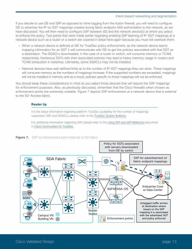
If you decide to use ISE and SXP as opposed to inline tagging from the fusion firewall, you will need to configure ISE to advertise the IP-to-SGT mappings created during fabric endpoint AAA authorization to the network, as we have discussed. You will then need to configure SXP between ISE and the network device(s) at which you select to enforce the policy. Two points that were made earlier regarding enabling SXP learning of IP-SGT mappings at a network device such as a router or a switch are covered in detail here again because you must not overlook them:
• When a network device is defined at ISE for TrustSec policy enforcement, as the network device learns mapping information for an SGT it will communicate with ISE to get the policies associated with that SGT as a destination. The SGACLs downloaded, in the case of a router or switch, will consume memory or TCAM, respectively. Numerous SGTs with their associated policies may lead to heavy memory usage in routers and TCAM exhaustion in switches. Ultimately, some SGACLs may not be installed.
• Network devices have well-defined limits as to the number of IP-SGT mappings they can store. These mappings will consume memory as the numbers of mappings increase. If the supported numbers are exceeded, mappings will not be installed in memory and as a result, policies specific to those mappings will not be enforced.
You should keep these considerations in mind as you select those devices that will require the SXP mappings for enforcement purposes. Also, as previously discussed, remember that the Cisco firewalls when chosen as enforcement points are extremely scalable. Figure 7 depicts SXP enforcement at a network device that is external to the SD-Access fabric.
Reader tip
For the latest information regarding platform TrustSec scalability for the number of mappings supported, SXP, and SGACLs, please refer to the TrustSec System Bulletins.
For additional information regarding SXP, please refer to the Using SXP and SXP Reflectors document in Cisco Communities for TrustSec.
Figure 7. SXP to enforcement point external to the fabric
Enterprise Coreor Data Center
BorderNodes
SGFW/ASA-OS
Enforcement points
SXP for advertisement offabric endpoint mappings
Campus VNBuilding VN
SDA Fabric
FA
IP
CO
EM
HV
IP
Policy for SGTs associatedwith servers downloaded
from ISE by switch
Untagged traffic arrives at destination where based on the SXP
mapping it is associated with the advertised SGT
and policy enforced

page 14Cisco Validated Design
Intent-based networking and segmentation
One difference that you will encounter if choosing to use SXP as opposed to inline tagging is that without additional configuration, other than that described previously, enforcement of server traffic or other external endpoints to a fabric endpoint based on SGT is not possible. This additional configuration is required because the external traffic will arrive at the fusion firewall without an SGT and hence is unusable in a SGT-based policy.
To configure this, you must propagate the IP-to-SGT mappings for the external devices to the fusion firewall for use as the source SGT. This will then allow you to enforce policies where the source is external to the fabric and the destination is a fabric endpoint, as depicted in Figure 8.
Figure 8. Enforcing policy for external traffic destined to fabric
Enterprise Coreor Data Center
BorderNodes
Fusion FW-ASA-OS
Enforcement points
SXP for advertisement of bothfabric and external endpoint
mappings
Campus VNBuilding VN
SDA Fabric
FA
IP
CO
EM
HV
IP
Untagged external traffic arrives at fusion firewall. As SXP mappings are present, fusion firewall will enforce
policies based on SGT
Enforcement of traffic within and between virtual networksWithin each VN, one or more scalable groups can be defined providing SGT-based microsegmentation within that VN. Policies defining communications between SGTs within each VN are defined at DNA-C, communicated to ISE through REST API, and subsequently distributed by ISE to the edge nodes of the SD-Access fabric. As endpoints attach to the edge nodes, the edge node will request the applicable policy for that SGT if not already present, and install it in TCAM. For enforcement within the VN, the only requirements are that the policies and associated contracts have been created for the VN, defining what communications between SGTs are permitted or dropped.
You can also enforce Policies using SGTs to permit or deny traffic between VNs. When you create VNs, you will have the option to assign scalable groups to that VN. When building a policy in DNA-C you will specify a source and destination SGT. If the policy you are creating is going to use an SGT from another VN, you will need to define that SGT as being VN agnostic as seen below.
As with enforcement between the fabric endpoints and external destinations, you have two options for policy enforcement for traffic between VNs:
1. Enforce at the fusion firewall serving as an SGFW2. Enforce at the destination edge node.
Because scalable groups can be assigned only to a single VN today, it is not possible to create a VN policy in DNA-C where the source or destination SGT of one VN also resides in another VN.

page 15Cisco Validated Design
Intent-based networking and segmentation
For enforcement between VNs using a fusion firewall, you will configure ISE to advertise the IP-SGT mappings derived during fabric endpoint authorization, as discussed earlier. These mappings are used at the SGFW in rule creation to enforce your policy. Again, if you are using ASA OS on your ASA or Firepower SGFW, you will be able to create your rules using any combination of SGTs and IP addresses as sources or destinations. If, however, you are using the Firepower FTD, your rules need to use destination IP addresses. Figure 9 depicts the scenario described.
Figure 9. Enforcement of traffic within and between virtual networks
Enterprise Coreor Data Center
BorderNodes
SGFW/ASA-OS
Possibleenforcement points
SGT carried nativelyin the SDA fabric
Campus VNBuilding VN
SDA Fabric
FA
IP
ST
EM
HV
IP
SXP for fabricendpoints
page 16Cisco Validated Design
Defining network segments
Defining network segmentsThe decision to create network segments, whether virtual or logical, should be driven by the organization’s business requirements. But what does that really mean? First and foremost, what are the goals of segmenting the network?
Implementing network segmentation allows you to define segments, whether virtual (virtual networks) or logical (SGTs), that are dedicated to a specific business application or function for security reasons. These segments can have well-defined policies governing access to a segment and the ability to limit communications between them. When implementing segmentation, you minimize the network attack surface to, at most, that segment, while additionally defining security policies within and outside of the network segments in the case of virtual networks, or between and within logical segments in the case of SGTs.
As previously discussed, SD-Access offers both network segmentation through the use of virtual networks as well as “logical” segmentation through the use of SGTs within each virtual network. Realistically, you could decide to use all virtual networks with a single scalable group in each or, alternatively, a single “user” virtual network with multiple scalable groups.
The approach taken will depend largely on whether there is a need for complete isolation of an application or business function. In cases such as Payment Card Industry (PCI) and guest networks, the complete isolation found with a virtual network is likely the best choice. When using a virtual network, the scope of regulatory compliance, for example, is limited to access to the virtual network and communications within it. Alternatively, scalable groups with policies controlling communications between tags can provide the necessary segmentation “logically” for point-of-sale (POS) machines and card readers. In the case of PCI, though, you will need to be prepared to demonstrate isolation between the PCI tag and other SGTs belonging to that virtual network. There is no single correct answer, and most customers will likely choose a combination.
Some examples of where virtual networks might be used are:
• PCI: POS machines, card readers, and payment card gateways
• Electrical power: Separation of generation, transmission, and corporate networks
• Building controls: Heating, cooling, lighting, and security systems
• Manufacturing floors: Isolating the floor from the corporate network
• Trading floors
• Management of network infrastructure
• Research and development: Isolating the research environment from the corporate network.
• University dormitories: Isolating them from the campus network and applications
• Healthcare clinical environments: Bedside monitors, infusion pumps, MRI, ultrasound, and X-ray
• Guest networks
Some examples of where SGTs might be used are:
• PCI: Inventory scanners, card readers, POS
• Healthcare clinical environments: Bedside monitors, infusion pumps, MRI, ultrasound, X-ray, doctors, nurses, building controls.
• University: Students, professors, guests, building controls, and security systems
page 17Cisco Validated Design
Defining network segments
• Business functions such as human resources or finance
• Security systems and other business controls
• Guest access
• Contractor access
• Business partners
• Quarantine and remediation
• Network administration
As can be seen from the above examples, there may be a great deal of overlap where virtual networks, SGTs, or a combination may be used to segment the network. Hence, as we discuss the topic of segmentation we really need to be able to make a distinction as to which methods will satisfy the business security requirements without creating unnecessary design complexity.
Virtual networks or scalable group tagsIn the previous sections, we have gone through the various segmentation technologies used both with and without SD-Access. What are the business requirements driving the need for segmentation?
Virtual networksIt is often very easy to identify those requirements that compel an organization to completely isolate segments from one another, as in virtual networks and VRFs. Typically, this requirement is established in order to attain regulatory compliance by maintaining security controls between various types of business communications. When evaluating whether or not a specific business function or application warrants its own virtual network, it is important to assess the following criteria:
• Does the application or business function as well as the devices accessing it extend from the edge of the network into the core?
• Are the user and device communications primarily limited to that virtual network, with only limited access required in or out of the virtual network?
• Within a virtual network, will communications between devices be allowed?
• Will the scope of a network audit for regulatory compliance be reduced with the isolation enabled by a virtual network or VRF?
Generally, if the answers to all of the above are yes, this may sway the decision to define a virtual network or VRF for these applications and functions. When SD-Access has been deployed, routing complexity within the fabric is eliminated by virtue of the overlay’s VXLAN data plane and LISP control plane; the routing considerations are moved to the edge of the fabric. At the border of the fabric there will still be a need to use either a fusion router or firewall for any necessary route leaking between SD-Access virtual networks and the external networks.
An example of when a separate virtual network would be useful is for PCI Data Security Standard (PCI-DSS) compliance, where security controls must be implemented restricting all access to cardholder data and transmissions. Placing all devices that will either collect, store, or transmit credit card transactions within a virtual network will drastically reduce the scope of a PCI audit, providing limited access to that environment with the appropriate policy enforcement logging capabilities.
page 18Cisco Validated Design
Defining network segments
A second example of the use of virtual networks can likewise be found in the electrical power industry. In this industry, a need exists to maintain complete isolation between networks identified as supporting critical infrastructure, namely power generation and transmission, and normal corporate operations. In this example the extremely limited communications that are required between networks is permissible only through stateful firewalls.
Other similar examples of the use of virtual networks and the need to isolate communications within them can be found in manufacturing floors, building systems, and guest networks. From a manufacturing perspective, the threat of loss of intellectual property is one of the main issues, but of equal concern is the need to isolate the factory floor because the Internet of Things (IoT) has become vulnerable to malware that may literally take a company’s manufacturing hostage. Building systems such as HVAC, secure entry, and video surveillance should likewise be isolated from the rest of an organization’s networks, providing only limited access to those in maintenance or security. Finally, facilitating a guest network is a perfect example of an instance where the isolation offered by a virtual network enables the organization to grant only Internet access and nothing else.
In all of these examples it is apparent that the use of virtual networks reduces the complexity of enforcing a security policy by strategically limiting access to only those that need it, using only specific protocols, while also offering rich logging capabilities when firewalls are used as fusion devices controlling inter-virtual network or traffic destined for outside the SD-Access fabric.
When considering the number of virtual networks that need to be defined, the most important consideration is the number of virtual networks supported across the network devices comprising the SD-Access fabric. Virtual networks are a fabricwide construct. As such, if you define 15 virtual networks, for example, all fabric devices regardless of definition as an edge node or border node must be able to support 15 virtual networks. This consideration will typically come into play at the edge nodes where they may be some combination of a Catalyst 3850 or 3650. So, for example, the Catalyst 3850 and 3650 Switches support a maximum of 32 virtual networks, whereas DNA Center 1.1.3 supports up to 64 virtual networks with the Catalyst 9300 supporting more. Hence with Catalyst 3850s installed in a fabric running DNA Center 1.1.3, you will be limited to 32 virtual networks.
Also, when considering the number of virtual networks that need to be defined, another important consideration is that if communications between virtual networks is a requirement, some form of route leaking will be required. For example, if a virtual network was dedicated to employee devices only and a second virtual network was established for collaboration devices only, it would be necessary to provide a means of route leaking for collaboration applications such as Cisco Jabber® or Cisco Spark™ on employee devices to communicate with IP phones, Cisco Spark Boards, or video endpoints. In essence, you need to concern yourself not only with ensuring that route leaking is enabled for the appropriate address ranges, but also, from a policy perspective, with ensuring that you have identified all of the UDP ports that will have to be allowed for successful communications. Likewise, the creation of separate virtual networks based on business functions such as HR, finance, and accounting, or on types of users such as students, faculty, and administration and the associated route leaking that would be required could become quite cumbersome. In these examples, the use of scalable groups to segment the users within a single virtual network should be considered as well.
As part of the routing considerations with SD-Access, you also need to understand that new IP addressing strategies need to be implemented for creation of the underlay network as well as for use within each of the virtual networks you may choose to create.
The best approach to creating dedicated virtual networks is to start small and grow into it. The examples highlighted above are very easily identified in that strict isolation is required with only minimal access required into and out of the segment.
Scalable group tagsWhen dealing with other applications or business requirements that require security policy controls while still allowing communication between devices within the same virtual network, but that do not need isolation at the network layer, the use of SGTs offers an effective segmentation strategy. One of the main benefits of using SGTs as opposed to using virtual networks alone is the ability to micro-segment the network, even within a virtual network in SD-Access. Here, for example, policies and contracts can be created that restrict what communications are allowed between devices with different SGTs or with the same SGT, even when attached
page 19Cisco Validated Design
Defining network segments
to the same switch. This capability reduces the attack surface through the ability to limit the horizontal spread of malware not only between scalable groups but even between members of the same group based on the contract or SGACL and the Layer 4 access control entries within a policy.
As an example of the use of SGTs for segmentation, consider a university environment in which there are different types of users and devices such as faculty, employees, students, printers, and even campus facilities and security. Here the need for segmentation, even between students and campus facilities or security, may be addressed through the isolation offered by scalable groups.
Another example can be found in the corporate operations of any business that desires to segment employees, interns, contractors, vendors, human resources, finance, and executive management through the use of SGTs. This segmentation easily identifies the general population of employees with an SGT and isolates them from any corporate accounting or personnel data.
During corporate mergers and acquisitions, the addition of new employees, or even the transfer of employees during or after a corporation divesture of a portion of the business, can easily be accommodated through the use of scalable groups. The ability to then create policies granting the affected employees access to applications and resources they still need, while isolating them from the unaffected employees, assists in providing the policy-based controls necessary to restrict access to proprietary information.
As can be seen in these examples, there may not be a compelling reason to implement the network isolation provided by the use of virtual networks. In all of these examples, the segmentation requirements may be adequately met with the security controls available with group-based policies based on scalable groups. In fact, as discussed earlier, only the use of scalable groups within a virtual network or legacy VRF can minimize the horizontal attack surface between members of the same virtual network or scalable group.
When evaluating the segmentation strategy in an SD-Access fabric for the creation of virtual networks, and subsequently the scalable groups assigned to the virtual network, you have the flexibility to create virtual networks with a single scalable group assigned, or a single virtual network with all scalable groups assigned to that single virtual network. This decision will obviously be affected by what, if any segmentation strategy, you currently have deployed.
When considering the use of scalable groups within an SD-Access virtual network, there are several factors to consider:
• Policies with contracts implementing numerous Layer 4-based access control entries applied to source/destination pairs (cell in a policy matrix; x:y axis) should be the exception and not the norm.
• As it is not possible today to implement a firewall within a virtual network of an SD-Access fabric, stateful packet inspection between SGTs is not possible; SGT-based policies and associated contracts will be used.
• Careful consideration of the criteria requiring a unique SGT should be defined, as well as the overall number of SGTs to be supported.
It is important to understand that the policies and the contracts, or SGACLs, they consist of will consume switch TCAM. The use of contracts or SGACLs with numerous access control entries may result in TCAM exhaustion, after which new policies may not be programmed. When possible, keep the policies as simple as possible. Understand also that group-based policies will not provide the same stateful packet inspection and detailed logging capabilities offered by a firewall.
That said, it is equally important to understand that in most cases the segmentation offered through the use of scalable groups provides excellent security controls between users and devices in the same virtual network. Today, many organizations and government agencies have been implementing Cisco TrustSec as either the sole or at least the major technology in addressing their segmentation strategy.
As testament to this, the use of a specific SGT dedicated to PCI devices may be considered as an effective security control for POS machines and card readers by many assessors, thereby reducing the scope of the audit in the extended network. This again highlights the ability to use either approach, virtual networks or SGTs, in the creation of a secure segmentation strategy.
page 20Cisco Validated Design
Defining network segments
Reader tip
The use of SGTs as a security control for POS machines and card readers is solely at the discretion of the PCI assessor for the audit. The use of SGTs in past audits, however, has been accepted as evidence of a security control. Any organization preparing for a PCI audit should discuss this beforehand with its assessor. For one story, please refer to the following URL https://www.cisco.com/c/dam/en/us/solutions/collateral/enterprise-networks/trustsec/trustsec_pci_validation.pdf
Although it is possible to deploy virtual networks without using scalable groups in an SD-Access fabric, at least one virtual network must exist in which the scalable groups will reside. By default, this is the DEFAULT_VN.
When implementing scalable groups within virtual networks, the use of SGTs for the creation of group-based policies will be limited to the SD-Access fabric and at the border. As traffic egresses a virtual network at the border node, a group-based policy can be enforced for external destinations, either at the border, depending on the platform, or at a device adjacent to the border node. If there is a desire to extend the use of SGTs and Cisco TrustSec elsewhere in the network, Cisco TrustSec inline tagging and/or SXP will be required to propagate the tag information to external, non-fabric networks.
When implementing an SD-Access Distributed Campus deployment configured with an SD-Access transit site, the SGT will be communicated seamlessly without the need to use Cisco TrustSec inline tagging or SXP, because the SGT will be carried in the VXLAN header between the border nodes of each fabric.
Reader tip
For more information about SD-Access Distributed Campus Deployment, refer to the SD-Access e-book at https://www.cisco.com/c/dam/en/us/products/se/2018/1/Collateral/nb-06-software-defined-access-ebook-en.pdf.
For more information regarding SD-Access migration, refer to the SD-Access Migration Guide at https://www.cisco.com/c/en/us/solutions/collateral/enterprise-networks/software-defined-access/guide-c07-739524.html.
One final point to consider is that, much like the consideration paid to the number of virtual networks created, the number of scalable groups to create must be evaluated. Although assigning an SGT to each major department within an organization is quite normal and acceptable, you should not try to subdivide departments into numerous other roles within that department.
Taking a university environment as an example, you may define an SGT for “professor.” You then might realize that you want to break that down into departments such as math, physics, biology, and languages. The question you should ask yourself is if there really is a need to create multiple department-based SGTs for professors, each with unique policies, or whether it really matters that all of these departments share a common SGT with the same access to servers and other data.
The best approach to defining scalable groups is not to create a group for every possible role, function, device type, etc., upfront. Doing so will not only lead to extensive policy creation but will additionally require more TCAM and memory resources for SGACL storage on switches and routers. In almost all cases, extensive group definitions and the ensuing policy creation will minimally slow down any segmentation project as all contributors discuss the benefit of one policy versus another, also known as “analysis paralysis.” Then, even if you are fortunate enough to agree quickly on groups and policies, as the policy is implemented, changes will inevitably need to be made to address an oversight, resulting in a possible denial of service and a ripple effect of policy changes.
Similar to evaluating a VN strategy, start out small and start slowly. Identify those groups for which tangible benefits can be derived immediately from the ability to limit access to specific applications and data. Once the effectiveness of the initial policies has been determined, you can easily modify them as necessary while also determining whether or not additional group definitions may be necessary.
page 21Cisco Validated Design
Use cases
Use casesThe following use cases are intended to show some examples of how virtual networks and scalable groups may be used to implement segmentation within an SD-Access fabric. As discussed, virtual networks offer the first layer, or macro level, of network segmentation, completely isolating the traffic of one virtual network from the others. The second layer, or micro level, of segmentation, using scalable groups, can then be applied to traffic within the virtual network. The use of scalable groups within a virtual network is purely optional but does provide additional security in the ability to restrict traffic between endpoints in different scalable groups, or even to restrict communications between members of the same group through the use of Cisco TrustSec group-based policies.
Caution
The examples below are just that. They do not represent a validated approach to segmenting a network within the scenarios depicted. Every organization will have its own requirements and goals when implementing segmentation, and these use cases just offer some examples for your consideration.
UniversityThe campus of a university may be one of the most challenging environments to secure. With numerous personal devices brought onto the campus, streaming and gaming applications in dorms, the number of compromised Internet sites students may visit, and even the possibility of a student deliberately launching malware, securing this environment is certainly challenging.
Introducing segmentation into the university will provide an additional layer of security through the ability to isolate traffic. Deploying specific virtual networks, such as dormitories vs. classrooms, lecture halls, and labs in the campus proper, allows administrators to isolate those environments from one another. Additionally, micro-segmentation through the use of scalable groups within each of the virtual networks provides the ability, through the use of Cisco TrustSec policies, to further restrict communications between groups within the respective virtual networks.
Figure 10 provides one example of how a university campus might be segmented when implementing SD-Access.
page 22Cisco Validated Design
Use cases
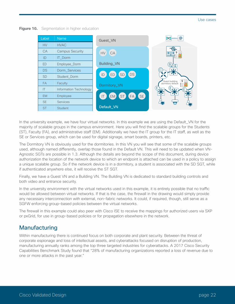
Figure 10. Segmentation in higher education
Guest_VN
Building_VN
CAHV
Dormitory_VN
EDID SD DS
Default_VN
EM ST FA SEIT
Label Name
HV HVAC
CA Campus Security
ID IT_Dorm
ED Employee_Dorm
DS Dorm_Services
SD Student_Dorm
FA Faculty
IT Information Technology
EM Employee
SE Services
ST Student
E E
Guest buildingdormitory default
CC
E
B
In the university example, we have four virtual networks. In this example we are using the Default_VN for the majority of scalable groups in the campus environment. Here you will find the scalable groups for the Students (ST), Faculty (FA), and administrative staff (EM). Additionally we have the IT group for the IT staff, as well as the SE or Services group, which can be used for digital signage, smart boards, printers, etc.
The Dormitory VN is obviously used for the dormitories. In this VN you will see that some of the scalable groups used, although named differently, overlap those found in the Default VN. This will need to be updated when VN-Agnostic SGTs are possible in 1.3. Although the details are beyond the scope of this document, during device authorization the location of the network device to which an endpoint is attached can be used in a policy to assign a unique scalable group. So if the network device is in a dormitory, a student is associated with the SD SGT, while if authenticated anywhere else, it will receive the ST SGT.
Finally, we have a Guest VN and a Building VN. The Building VN is dedicated to standard building controls and both video and entrance security.
In the university environment with the virtual networks used in this example, it is entirely possible that no traffic would be allowed between virtual networks. If that is the case, the firewall in the drawing would simply provide any necessary interconnection with external, non-fabric networks. It could, if required, though, still serve as a SGFW enforcing group-based policies between the virtual networks.
The firewall in this example could also peer with Cisco ISE to receive the mappings for authorized users via SXP or pxGrid, for use in group-based policies or for propagation elsewhere in the network.
ManufacturingWithin manufacturing there is continued focus on both corporate and plant security. Between the threat of corporate espionage and loss of intellectual assets, and cyberattacks focused on disruption of production, manufacturing annually ranks among the top three targeted industries for cyberattacks. A 2017 Cisco Security Capabilities Benchmark Study found that “28% of manufacturing organizations reported a loss of revenue due to one or more attacks in the past year.”

page 23Cisco Validated Design
Use cases
The ISA99 (International Society of Automation) standards committee is continually working on new standards for industrial automation and control systems security. This work encompasses securing not only software and monitoring systems but also manufacturing operations and controls.
In addition to the efforts underway to transform manufacturing by building security into all aspects of the communications protocols used and access to critical processes, network segmentation can offer an additional layer of security while providing the ability to enforce policies controlling access to various systems.
Figure 11 depicts a possible segmentation strategy that a manufacturing network might follow. It depicts three fabrics with a firewall connecting them. Two of the SD-Access fabrics actually contain two virtual networks in each, Enterprise/Building and Factory/Building. This depiction is only one example, and in fact it would be entirely possible to implement a single fabric with all four virtual networks defined and a firewall connecting the individual virtual networks together. Within each of the virtual networks are two or more scalable groups providing micro-segmentation within the virtual network.
With this segmentation strategy, four virtual networks, Building, Enterprise, IDMZ, and Factory, are established with intercommunications allowed only through the firewall depicted in the figure. The firewall would have scalable group information from all four virtual networks. The SGTs could then be used in policy creation, restricting access between those virtual networks to only the minimal communications required.
Figure 11. Segmentation in manufacturing
Default_VN
Building_VN
SEHV
Enterprise_VN
EMPL AC CO SU
HR
IDMZ_VN
AP ISJU
Factory_VN
SCOP BA PR
Label Name
HV HVAC
SE Security
CO Contractor
AC Accounting
HR Human Resources
PL Plant Operations
EM Employee
JU Jump Boxes
AP Industrial Applications
IS Industrial Services
OP Site Operations
SC Supervisory Control
BA Basic Control
PR Process
SU Supplier
E
E
E
E
E
E
Enterprise/Building
IDMZ
Factory/Building
CCCC
CC
B
BB
EEE
The Enterprise VN has scalable groups defined for various types of users. Each group would have access to only those resources in the data center or elsewhere (not depicted) and little or no access to users and devices in other scalable groups. Within the virtual network, policies can be established identifying any permissible communications between groups or simply denying all access.
The Building VN is fairly self-explanatory, with all building controls resident within. In the example we have physical security such as door swipes and locking mechanisms, video surveillance, HVAC, and potentially others, such as building lighting, digital signage etc. The only access to the Building VN would be for administrators or contractors requiring maintenance access to those systems.
page 24Cisco Validated Design
Use cases
The Factory VN is for all factory floor operations and really is the segment with the highest security requirements. In the Factory VN we provide micro-segmentation for further policy controls between scalable groups. The groups defined within would typically be used for the supervisory controls that monitor and automate the manufacturing process between the various processes or work cells, while the other SGTs are used for numeric control, conveyor systems, robots, etc. Normally, the only network access for operations staff to the Factory VN is through the IDMZ behind the firewall; users would most likely have access only via VDI servers located in the IDMZ.
Finally, the IDMZ restricts all communications to the factory floor. If a plant employee or employee in the Enterprise VN requires access to resources in the Factory VN, the only means would be through a VDI jump box in the IDMZ. Services such as Network Time Protocol and Active Directory required for any factory operations are dedicated to those operations in the Factory VN and would also reside in the IDMZ. Any manufacturing applications would reside in the IDMZ and be accessed from the Factory VN endpoints.
HealthcareAttacks on the healthcare industry continue to grow on an annual basis, with criminal attacks via ransomware and malware being the most common attack vector. Historically, the healthcare industry has been playing catchup in implementing security controls to secure its environments. With many rich targets to choose from, such as patient information, financial and credit card data, and research data, it is little wonder this industry has been an increasingly favorite target of malicious attacks.
Network segmentation has been adopted by a large number of healthcare providers as a means of adding additional security controls through the use of well-defined policies governing access to critical systems and patient data. Network segmentation in healthcare provides a means by which the various systems or functions can be broken up into smaller environments or segments while then restricting access between and within segments.
Although some organizations have deployed VRFs and even MPLS, most hospitals or healthcare campuses have typically built out discrete clinical networks serving only the patient floors separated from the administrative environment by means of a firewall. Normally, this has been the only real segmentation for the institution, outside of the server farms at the hospital or data center in larger campus settings.
Figure 12 depicts two separate fabrics, one for the administrative functions and another for the clinical environment. It follows the established practice of maintaining two discrete networks for each environment. Realistically, there is no reason that a single fabric with segmentation provided through the use of virtual networks and SGTs would not suffice.
In each of the two fabrics depicted, virtual networks have been defined to segment devices and communications in the Admin virtual network or Clinical virtual network with other segments (virtual networks) set aside for building management, guest services, and even PCI. As can be seen in Figure 12, the Building, Guest, and PCI VNs extend between both fabrics, as they are applicable to both environments.
The two fabrics/environments, Admin and Clinical, are connected by means of a firewall that restricts access between them as well as interconnecting the four virtual networks within each fabric. Although fairly uncommon, communications between virtual networks may be necessary. In such circumstances, users might need to use VDI dedicated to that virtual network, thereby eliminating the risk of introducing malware resident on the user’s device into another virtual network.
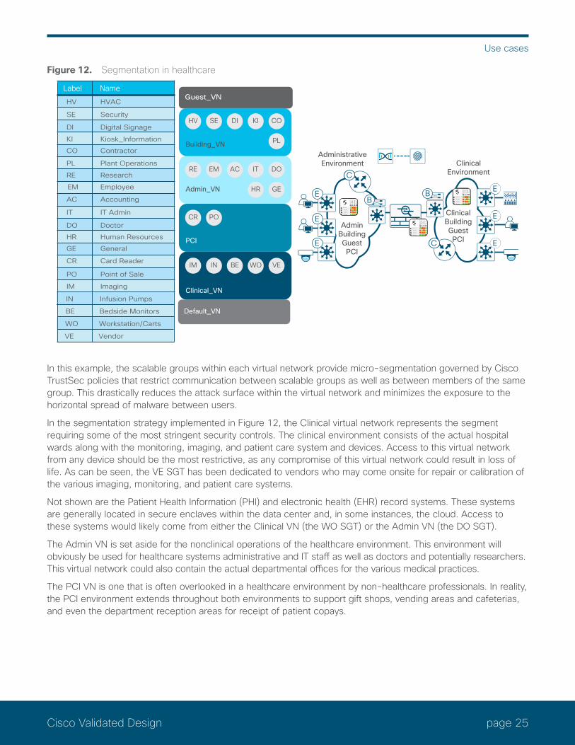
page 25Cisco Validated Design
Use cases
Figure 12. Segmentation in healthcare
Guest_VN
Default_VN
Building_VN
SEHV DI KI CO
PL
Admin_VN
EMRE AC IT DO
GEHR
PCI
Clinical_VN
INIM BE WO VE
Label Name HV HVAC
SE Security
PL Plant Operations
CO Contractor
EM Employee
DI Digital Signage
KI Kiosk_Information
AC Accounting
IT IT Admin
DO Doctor
HR Human Resources
GE General
CR Card Reader
PO Point of Sale
IN Infusion Pumps
WO Workstation/Carts
VE Vendor
RE Research
E
E
E
AdminBuildingGuestPCI
ClinicalBuildingGuestPCI
CC
CC
BB
ClinicalEnvironment
AdministrativeEnvironment
IM Imaging
BE Bedside Monitors
E
POCR E
E
In this example, the scalable groups within each virtual network provide micro-segmentation governed by Cisco TrustSec policies that restrict communication between scalable groups as well as between members of the same group. This drastically reduces the attack surface within the virtual network and minimizes the exposure to the horizontal spread of malware between users.
In the segmentation strategy implemented in Figure 12, the Clinical virtual network represents the segment requiring some of the most stringent security controls. The clinical environment consists of the actual hospital wards along with the monitoring, imaging, and patient care system and devices. Access to this virtual network from any device should be the most restrictive, as any compromise of this virtual network could result in loss of life. As can be seen, the VE SGT has been dedicated to vendors who may come onsite for repair or calibration of the various imaging, monitoring, and patient care systems.
Not shown are the Patient Health Information (PHI) and electronic health (EHR) record systems. These systems are generally located in secure enclaves within the data center and, in some instances, the cloud. Access to these systems would likely come from either the Clinical VN (the WO SGT) or the Admin VN (the DO SGT).
The Admin VN is set aside for the nonclinical operations of the healthcare environment. This environment will obviously be used for healthcare systems administrative and IT staff as well as doctors and potentially researchers. This virtual network could also contain the actual departmental offices for the various medical practices.
The PCI VN is one that is often overlooked in a healthcare environment by non-healthcare professionals. In reality, the PCI environment extends throughout both environments to support gift shops, vending areas and cafeterias, and even the department reception areas for receipt of patient copays.
page 26Cisco Validated Design
Use cases
The Building VN allows for complete isolation of facility or campuswide building, security, and information systems. Information kiosks, digital signage, and video streaming for patient and guest entertainment in the hospital rooms and waiting areas could be located in the Building VN.
Finally, the Guest VN is provided for all patient and visitor Internet access.
PCI and retailAs anyone who has ever undergone a PCI audit knows, the amount of information and time required to provide network diagrams, evidence of controls securing cardholder data, whether at rest or in transit, what is in versus out of scope, and sample reporting and logs is extensive. Although storage of cardholder data will always be behind a firewall capable of stateful inspection and threat detection, other components such as POS machines and card readers placed throughout the network will also be in scope.
In securing the Cardholder Data Environment (CDE) residing in the data center, security controls are more easily identified and deployed through the use of NGFWs in addition to segmentation strategies such as tenants and endpoint groups when Cisco ACI or even Cisco TrustSec is used.
In the branch and even campus environments, the controls prove to be more challenging and may significantly increase the scope of the PCI audit relative to the networks to which POS machines and card readers are attached. This is due to the fact that without segmentation, all things connected to the same network, be it wired or wireless, along with the POS machine, will fall within scope of a PCI audit.
Organizations such as retail, finance, and even healthcare can find relief in limiting the scope of a PCI Audit by implementing a segmentation strategy based on virtual networks and VRFs as well as scalable groups. Using a virtual network isolated from all others clearly not only reduces the scope but also addresses the requirement for secure access with detailed logging capabilities while restricting access through the use of firewalls.
Electric powerIn North America, the North American Electric Reliability Corporation (NERC) is the regulatory body responsible for assuring the reliability and security of the electrical power system through the implementation of Critical Infrastructure Protection (CIP) standards, while in Europe the European Union Agency for Network and Information Security (ENISA) has similar responsibilities that it addresses through the Smart Grid Architecture Model (SGAM). One of the fundamental requirements is for well-defined network boundaries isolating power generation, power transmission, and corporate operations from each other. Access between these networks is controlled through the use of firewalls. In this environment, the use of virtual networks is almost a given, due to the complete isolation required, with only limited, secure access permitted between the networks.
In Figure 13, a greatly simplified example of the use of network segmentation in an electric power company is provided. In this example three virtual networks have been defined and are used in addition to the DEFAULT_VN. The DEFAULT virtual network is used for all corporate facilities including employees, contractors, HVAC, and security systems companywide. The Power Generation VN is dedicated to powerplant operations, while the Power Transmission VN consists of substations instrumentation and control and field operations staff. Finally, a Guest VN is defined for corporate facilities. These three virtual networks provide the necessary isolation, with limited access provided through firewalls, meeting requirements for regulatory compliance.

page 27Cisco Validated Design
Use cases
Figure 13. Segmentation in electric power
Guest_VN
Default_VN
EMIT HV CO BU
Transmission_VN
SUIC FI OP SS
Generation_VN
SEPR PL PC
Label Name
PR Process
SE Plant Security
SU Substation
IC Instrumentaion and Control
OP Operations
PL Plant Operations
PC Plant Contractor
SS Substation Security
IT IT Staff
EM Employee
HV HVAC
CO Contractor
BU Building Security
FI Field
E
E
E
Defaultcorporate
Powertransmission
Powergeneration
CCCC
CC
B
BB
EEE
E
E
E
Within the individual virtual networks, a need exists to further micro-segment the network to restrict access between the scalable groups in that virtual network. The Transmission VN is a perfect example, where scalable groups are defined for power line instrumentation and control (IC), substation instrumentation and control (SU), substation security systems for keyed entry and IP surveillance (SS), field engineering and linemen for substation and power line maintenance (FI), and systemwide operations and control staff (OP). The need for micro-segmentation arises to restrict access between instrumentation and control endpoints and field resources while providing less restrictive access to operations where supervision and control of the power grid is required.

page 28Cisco Validated Design
Appendix A: Network segmentation overview: A brief history
Appendix A: Network segmentation overview: A brief history
Reader tip
This section is intended for those readers not familiar with network segmentation, including not only VLANs and VRFs but Cisco TrustSec® as well. If you are familiar with all of these concepts, you may simply want to skip to the next section, which covers network segmentation today.
The concept of network segmentation is not new, but it has evolved significantly over the last 20 or so years. Initially, network segmentation was defined as the process of breaking up one “flat” network/broadcast domain into smaller segments through the use of virtual LANs (VLANs). The original intent was to improve the overall performance of not only the network itself but also the endpoints by minimizing the number of broadcasts devices had to process.
However, as time went on, network segmentation through the use of VLANs was implemented for security reasons and for the ability to limit communications between segments through the use of Access Control Lists (ACLs) to enforce a business-related policy. VLANs initially provided a very basic means of isolating one segment (VLAN) and its devices from another. Private VLANs later provided a form of micro-segmentation, by further restricting communications within a VLAN.
Ultimately, as requirements were established to extend network segments across an enterprise regardless of location, the concept of Virtual Routing and Forwarding (VRF) instances was used to provide Layer 3 isolation between network segments. Isolation is inherent, as each VRF maintains its own routing table, creating a virtual network. Isolation is attained in that routes contained in one VRF are not present in another, thereby limiting communications between them.
Over the last 10 years Cisco developed a new technology known as Cisco TrustSec® that ultimately redefined the term “network segmentation.” With Cisco TrustSec, segmentation is no longer performed based on VLANs or VRFs with IP addressing and routing. Instead, Cisco TrustSec relies on the use of role- or group-based membership, irrespective of IP addressing, to create policies allowing for segmentation of the network.
VLANs and private VLANsIn the early days of networking, the term “network segmentation” was used to describe the process of splitting large, flat, Open Systems Interconnection (OSI) Layer 2 networks or broadcast domains into smaller network segments or OSI Layer 3 subnets. Ultimately, this limited the scope of broadcasts from attached endpoints within that subnet, thereby increasing overall network performance while at the same time providing a way to isolate endpoints. Obviously, the concept of these individual Layer 2 segments was ultimately incorporated into the IEEE 802.1Q standard, and the segments were called VLANs.VLANs provide a means of isolating device traffic in one segment or VLAN from another, as all communications between VLANs must be routed through a Layer 3 interface. At this Layer 3 interface, ACLs can be applied to control what traffic can be forwarded or dropped based on IP address or application identified by TCP or User Datagram Protocol (UDP) port numbers. Initially, ACLs, known today as router ACLs, or RACLs, could be applied only at Layer 3 boundaries. However, as switching products evolved, it became possible to apply ACLs known as VLAN ACLs, or VACLs, to VLANs and ultimately Port ACLs known as PACLs to the physical interfaces. Albeit rudimentary by today’s standards, this provided an effective means of securing connectivity between devices within a VLAN or between VLANs, and for many organizations today is a strategy still in use, complemented by firewalls.

page 29Cisco Validated Design
Appendix A: Network segmentation overview: A brief history
Further enhancements to VLANs were made to provide additional segmentation with the introduction of private VLANs. Private VLANs consist of three different VLAN types: the primary VLAN with its promiscuous (P) port, the isolated VLAN with its isolated (I) port, and the community VLAN with its community (C) port. The (P) port of the primary VLAN is associated with either a switched virtual interface (SVI) or a port with a router attached. Ports (I) assigned to the isolated VLAN can communicate upstream only with the promiscuous (P) port, and the ports (C) assigned to the community VLAN can communicate with each other or with the (P) port. This can provide segmentation between the isolated ports, between the isolated ports and community VLANs, or between community VLANs. Any communication between isolated and community ports must be through the (P) port, where ACLs can be used to enforce a policy.
Reader tip
For more information regarding private VLANs, refer to the Cisco switching documentation or Cisco Learning documents such as https://learningnetwork.cisco.com/docs/DOC-16110.
Regardless of whether a network uses VLANs or private VLANs, as they are extended throughout the network, so too are the broadcast domains, requiring strategic configuration of spanning trees to ensure a loop-free and stable network topology.
Virtual routing and forwarding instancesAs we discussed, VLANs are the most basic path isolation technique for Layer 2. However, as the goal of every solid network design is to minimize the extent of the broadcast domain and exposure to spanning-tree loops, a method to translate the Layer 2 VLAN to a Layer 3 virtual network or VPN is required. This Layer 3 virtual network must be capable of supporting its own unique control plane, complete with its own addressing structure and routing tables for data forwarding and completely isolated from any other Layer 3 VPN on that device and in the network. The technology built upon this type of functionality is known as Virtual Routing and Forwarding (VRF). Figure A1 compares VLANs to VRF instances.
Figure 14. VRF/VLAN comparison
VLAN—Virtual LAN VRF—Virtual Routing and Forwarding
The VRF is defined on a networking device that serves as the boundary between the Layer 2, client-side VLANs and the Layer 3 network. Each VRF instance consists of an IP routing table, a forwarding table, and one or more interfaces assigned to it. Common routing protocols such as Open Shortest Path First (OSPF), Enhanced Interior Gateway Routing Protocol (EIGRP), Border Gateway Protocol (BGP), and Routing Information Protocol (RIP) v2 can be used to advertise and learn routes to populate the routing table unique to each virtual network through the use of address families. This routing information is then used to populate the Cisco Express Forwarding table using those interfaces, either logical ones (SVIs) or interfaces and subinterfaces that have been specifically allocated to that VRF through device configuration. VRFs exist on top of a global routing table, providing the required Layer 3 connectivity between network devices consisting of IPv4 prefixes and interfaces that have not been assigned to a VRF.
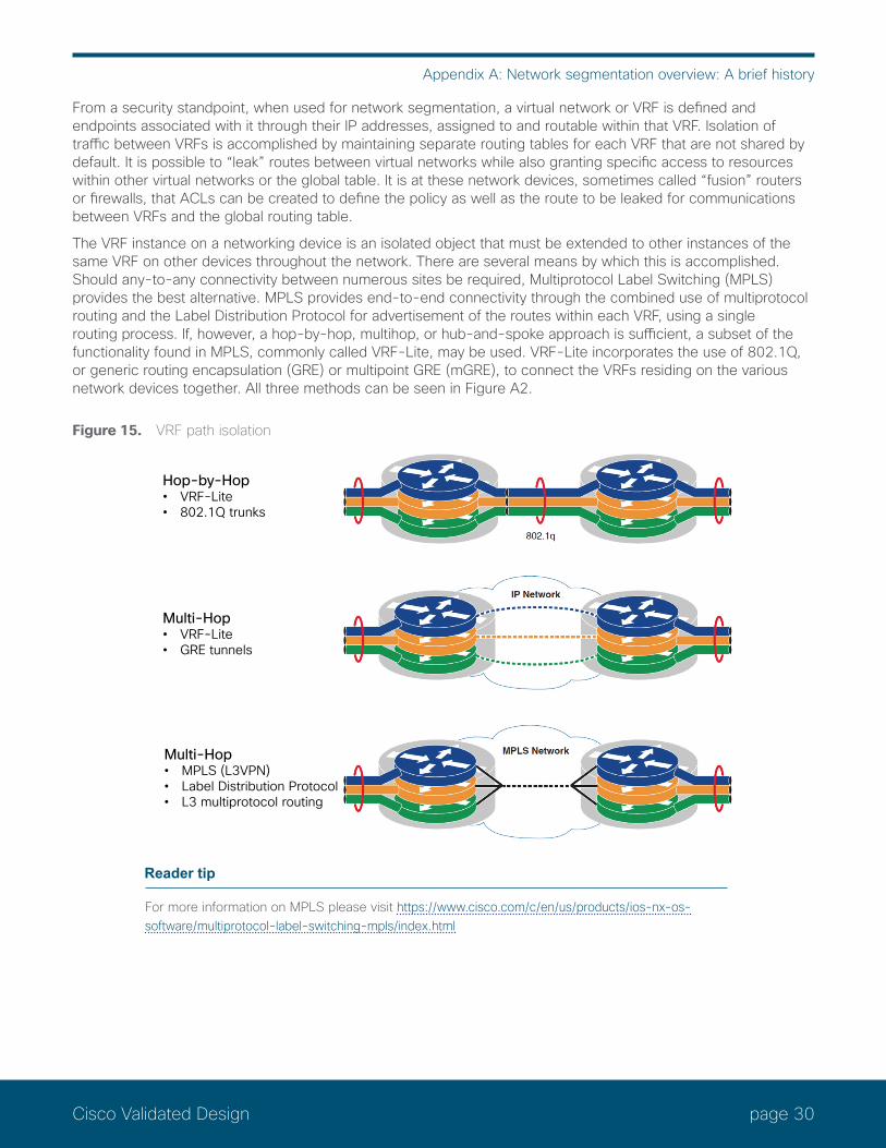
page 30Cisco Validated Design
Appendix A: Network segmentation overview: A brief history
From a security standpoint, when used for network segmentation, a virtual network or VRF is defined and endpoints associated with it through their IP addresses, assigned to and routable within that VRF. Isolation of traffic between VRFs is accomplished by maintaining separate routing tables for each VRF that are not shared by default. It is possible to “leak” routes between virtual networks while also granting specific access to resources within other virtual networks or the global table. It is at these network devices, sometimes called “fusion” routers or firewalls, that ACLs can be created to define the policy as well as the route to be leaked for communications between VRFs and the global routing table.
The VRF instance on a networking device is an isolated object that must be extended to other instances of the same VRF on other devices throughout the network. There are several means by which this is accomplished. Should any-to-any connectivity between numerous sites be required, Multiprotocol Label Switching (MPLS) provides the best alternative. MPLS provides end-to-end connectivity through the combined use of multiprotocol routing and the Label Distribution Protocol for advertisement of the routes within each VRF, using a single routing process. If, however, a hop-by-hop, multihop, or hub-and-spoke approach is sufficient, a subset of the functionality found in MPLS, commonly called VRF-Lite, may be used. VRF-Lite incorporates the use of 802.1Q, or generic routing encapsulation (GRE) or multipoint GRE (mGRE), to connect the VRFs residing on the various network devices together. All three methods can be seen in Figure A2.
Figure 15. VRF path isolation
Hop-by-Hop• VRF-Lite• 802.1Q trunks
Multi-Hop• VRF-Lite• GRE tunnels
Multi-Hop• MPLS (L3VPN)• Label Distribution Protocol• L3 multiprotocol routing
VRF path isolation
Reader tip
For more information on MPLS please visit https://www.cisco.com/c/en/us/products/ios-nx-os-software/multiprotocol-label-switching-mpls/index.html

page 31Cisco Validated Design
Appendix A: Network segmentation overview: A brief history
Cisco TrustSec—Software-defined segmentationWhile VRF-Lite and MPLS were starting to be adopted by non-service provider enterprises to provide network segmentation as a means of enforcing a security policy, an alternate means, using logical or software-defined constructs, was developed by Cisco known as Cisco TrustSec. Unlike VRF-Lite or MPLS, the Cisco TrustSec architecture is not reliant upon IP addressing and unique routing instances to provide isolation. Cisco TrustSec can be implemented without the need for VRFs. TrustSec is completely topology-independent.
At the heart of the Cisco TrustSec architecture are Security Group Tags (SGT). SGTs allow for the abstraction of a host’s IP address through the arbitrary assignment to a closed user group represented by an arbitrarily defined SGT. Typically, these groups align with those already created in Microsoft Active Directory or Lightweight Directory Access Protocol (LDAP). In the case of IoT, however, these endpoints generally do not have any correlation to such databases, and will be organized independently, based on purpose or type of device.
Reader tip
Prior to SD-Access, the acronym SGT referred to Security Group Tag. With SD-Access, SGT now refers to Scalable Group Tag because in the future, SGTs may be used for other purposes. QoS and policy-based routing are two such examples, having been implemented in TrustSec prior to SD-Access.
For centralized management of a Cisco TrustSec deployment, the Cisco Identity Services Engine (ISE) is required for both RADIUS-based identity services and SGT-based policy creation. The SGTs are created and centrally managed at the Cisco ISE. SGT assignment occurs upon successful authentication and authorization to the network through 802.1X, MAC Authentication Bypass (MAB), or WebAuth, or through the use of Active Directory and Windows Management Instrumentation (WMI). Once authorization is complete, ISE communicates the SGT associated with that device via RADIUS to the network device to which they are attached. This results in the mapping of an IP address to an SGT at the network device; this mapping is then used for device communications and policy enforcement. SGTs can also be manually defined on Cisco TrustSec capable switches and routers for a port, VLAN, subnet, or individual IP address, for those devices where dynamic authentication is either undesirable or not possible, such as servers in a legacy data center using the Cisco Nexus® 7000 Series Switches.
Reader tip
For further information about using TrustSec in the data center, please refer to the TrustSec Data Center Segmentation Guide.
The SGT can be either advertised as an IP address to SGT mapping via a TCP-based protocol known as the Scalable-Group Tag Exchange Protocol (SXP) communicated over pxGrid or carried as a 16-bit value within a Cisco proprietary field known as Cisco Metadata (CMD) inserted into an Ethernet frame, as seen in Figure A3. This is known as inline tagging.
Figure 16. SGT in Cisco Metadata
CMD
16 bit (64K SGTs)
(ETHTYPE:0x0800)
(ETHTYPE:0x8909)
SMACDMAC 802.1Q CMD ETYPE PAYLOAD ICV CRC
CMD EtherType Version Length SGT Opt Type SGT Value Other CMD Options
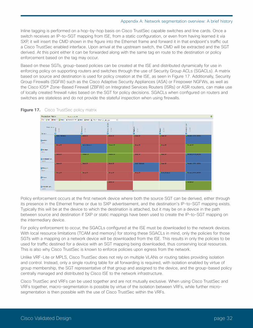
page 32Cisco Validated Design
Appendix A: Network segmentation overview: A brief history
Inline tagging is performed on a hop-by-hop basis on Cisco TrustSec capable switches and line cards. Once a switch receives an IP-to-SGT mapping from ISE, from a static configuration, or even from having learned it via SXP, it will insert the CMD shown in the figure into the Ethernet frame and forward it in that endpoint’s traffic out a Cisco TrustSec enabled interface. Upon arrival at the upstream switch, the CMD will be extracted and the SGT derived. At this point either it can be forwarded along with the same tag en route to the destination or policy enforcement based on the tag may occur.
Based on these SGTs, group-based policies can be created at the ISE and distributed dynamically for use in enforcing policy on supporting routers and switches through the use of Security Group ACLs (SGACLs). A matrix based on source and destination is used for policy creation at the ISE, as seen in Figure 17. Additionally, Security Group Firewalls (SGFW) such as the Cisco Adaptive Security Appliances (ASA) or Firepower NGFWs, as well as the Cisco IOS® Zone-Based Firewall (ZBFW) on Integrated Services Routers (ISRs) or ASR routers, can make use of locally created firewall rules based on the SGT for policy decisions. SGACLs when configured on routers and switches are stateless and do not provide the stateful inspection when using firewalls.
Figure 17. Cisco TrustSec policy matrix
Policy enforcement occurs at the first network device where both the source SGT can be derived, either through its presence in the Ethernet frame or due to SXP advertisement, and the destination’s IP-to-SGT mapping exists. Typically this will be at the device to which the destination is attached, but it may be on a device in the path between source and destination if SXP or static mappings have been used to create the IP-to-SGT mapping on the intermediary device.
For policy enforcement to occur, the SGACLs configured at the ISE must be downloaded to the network devices. With local resource limitations (TCAM and memory) for storing these SGACLs in mind, only the policies for those SGTs with a mapping on a network device will be downloaded from the ISE. This results in only the policies to be used for traffic destined for a device with an SGT mapping being downloaded, thus conserving local resources. This is also why Cisco TrustSec is known to enforce policies upon egress from the network.
Unlike VRF-Lite or MPLS, Cisco TrustSec does not rely on multiple VLANs or routing tables providing isolation and control. Instead, only a single routing table for all forwarding is required, with isolation enabled by virtue of group membership, the SGT representative of that group and assigned to the device, and the group-based policy centrally managed and distributed by Cisco ISE to the network infrastructure.
Cisco TrustSec and VRFs can be used together and are not mutually exclusive. When using Cisco TrustSec and VRFs together, macro-segmentation is possible by virtue of the isolation between VRFs, while further micro-segmentation is then possible with the use of Cisco TrustSec within the VRFs.
page 33Cisco Validated Design
Appendix A: Network segmentation overview: A brief history
Although Cisco TrustSec inline tagging can be supported when VRF-Lite is used for network connectivity, it not supported in MPLS environments where both Label Distribution Protocol and Cisco TrustSec are required on the interface. This is not a configuration limitation but an architectural one, whereby the label Forwarding Information Base (FIB) is used for next-hop processing, unlike the standard FIB, and hence the SGT and its IP association can’t be learned. In MPLS networks it is necessary to use SXP to “propagate” or communicate the IP-to-SGT mapping across the MPLS portion of the network.
Reader tip
For more information about Cisco TrustSec, please visit https://www.cisco.com/go/trustsec.
For additional information regarding platform support for TrustSec, please review the TrustSec Platform Support Matrix.

page 34Cisco Validated Design
Appendix B: References
Appendix B: ReferencesAccess Control Using Security Group Firewall: https://www.cisco.com/c/dam/en/us/solutions/collateral/enterprise/design-zone-security/access_control_using_security.pdf
APIC policy model: https://www.cisco.com/c/en/us/solutions/collateral/data-center-virtualization/application-centric-infrastructure/white-paper-c11-731310.html
Cisco’s architecture: https://www.cisco.com/c/en/us/solutions/intent-based-networking.html
Cisco Intent-Based Networking white paper: https://www.cisco.com/c/dam/en/us/solutions/collateral/enterprise-networks/digital-network-architecture/nb-09-intent-networking-wp-cte-en.pdf?oid=wpren006178
Enforcing Policy on an SD-Access Border Node: https://communities.cisco.com/docs/DOC-77432
SD-Access Design Guide: https://www.cisco.com/c/en/us/solutions/enterprise-networks/software-defined-access/index.html as well as the Cisco Validated Design SD-Access Design Guide at https://www.cisco.com/c/en/us/solutions/design-zone.html.
TrustSec Cisco Community on CCO: https://communities.cisco.com/community/technology/security/pa/trustsec
TrustSec on CCO: https://www.cisco.com/go/trustsec
TrustSec Platform Capability Matrix: https://www.cisco.com/c/dam/en/us/solutions/collateral/enterprise-networks/trustsec/software-platform-capability-matrix.pdf
TrustSec System Bulletins: https://www.cisco.com/c/en/us/solutions/enterprise-networks/trustsec/solution-overview-listing.html
TrustSec User-to-Data-Center Access Control Using TrustSec Deployment Guide: https://www.cisco.com/c/dam/en/us/td/docs/solutions/CVD/Apr2016/User-to-DC_Access_Control_Using_TrustSec_Deployment_April2016.pdf
TrustSec User-to-Data-Center Access Control Using TrustSec Design Guide: https://www.cisco.com/c/dam/en/us/td/docs/solutions/CVD/Oct2015/User-to-DC_Access_Control_Using_TrustSec_Design_October2015.pdf
TrustSec: Using SXP and SXP Reflectors: https://communities.cisco.com/docs/DOC-75763
Americas HeadquartersCisco Systems, Inc.San Jose, CA
Asia Pacific HeadquartersCisco Systems (USA) Pte. Ltd.Singapore
Europe HeadquartersCisco Systems International BV Amsterdam,The Netherlands
Cisco has more than 200 offices worldwide. Addresses, phone numbers, and fax numbers are listed on the Cisco Website at www.cisco.com/go/offices.
ALL DESIGNS, SPECIFICATIONS, STATEMENTS, INFORMATION, AND RECOMMENDATIONS (COLLECTIVELY, “DESIGNS”) IN THIS MANUAL ARE PRESENTED “AS IS,” WITH ALL FAULTS. CISCO AND ITS SUPPLIERS DISCLAIM ALL WARRANTIES, INCLUDING, WITHOUT LIMITATION, THE WARRANTY OF MERCHANTABILITY, FITNESS FOR A PARTICULAR PURPOSE AND NONINFRINGEMENT OR ARISING FROM A COURSE OF DEALING, USAGE, OR TRADE PRACTICE. IN NO EVENT SHALL CISCO OR ITS SUPPLIERS BE LIABLE FOR ANY INDIRECT, SPECIAL, CONSEQUENTIAL, OR INCIDENTAL DAMAGES, INCLUDING, WITHOUT LIMITATION, LOST PROFITS OR LOSS OR DAMAGE TO DATA ARISING OUT OF THE USE OR INABILITY TO USE THE DESIGNS, EVEN IF CISCO OR ITS SUPPLIERS HAVE BEEN ADVISED OF THE POSSIBILITY OF SUCH DAMAGES. THE DESIGNS ARE SUBJECT TO CHANGE WITHOUT NOTICE. USERS ARE SOLELY RESPONSIBLE FOR THEIR APPLICATION OF THE DESIGNS. THE DESIGNS DO NOT CONSTITUTE THE TECHNICAL OR OTHER PROFESSIONAL ADVICE OF CISCO, ITS SUPPLIERS OR PARTNERS. USERS SHOULD CONSULT THEIR OWN TECHNICAL ADVISORS BEFORE IMPLEMENTING THE DESIGNS. RESULTS MAY VARY DEPENDING ON FACTORS NOT TESTED BY CISCO.
Any Internet Protocol (IP) addresses used in this document are not intended to be actual addresses. Any examples, command display output, and figures included in the document are shown for illustrative purposes only. Any use of actual IP addresses in illustrative content is unintentional and coincidental.
© 2018 Cisco Systems, Inc. All rights reserved.
Cisco and the Cisco logo are trademarks or registered trademarks of Cisco and/or its affiliates in the U.S. and other countries. To view a list of Cisco trademarks, go to this URL: https://www.cisco.com/go/trademarks. Third-party trademarks mentioned are the property of their respective owners. The use of the word partner does not imply a partnership relationship between Cisco and any other company. (1110R)
Cisco Validated Design C07-740452-00 05/18
Please use the feedback form to send comments and suggestions about this guide.