SCRUB 50 - 55 - 65
60
ORIGINAL INSTRUCTION DOC. 10056728 - Ver. AC - 05-2016 SCRUBBING MACHINES USE AND MAINTENANCE MANUAL SCRUB 50 - 55 - 65
Transcript of SCRUB 50 - 55 - 65

ORIGINAL INSTRUCTION DOC. 10056728 - Ver. AC - 05-2016
SCRUBBING MACHINES
USE AND MAINTENANCE MANUAL
SCRUB 50 - 55 - 65


3
CONTENTSCONTENTS ..........................................................................................................................................3SYMBOLS USED IN THE MANUAL ...................................................................................................5PURPOSE AND CONTENT OF THE MANUAL ..................................................................................6TARGET GROUP .................................................................................................................................6STORING THE USE AND MAINTENANCE MANUAL ........................................................................6ON DELIVERY OF THE APPLIANCE .................................................................................................6INTRODUCTORY COMMENT .............................................................................................................6IDENTIFICATION DATA .......................................................................................................................6TECHNICAL DESCRIPTION ...............................................................................................................6INTENDED USE ...................................................................................................................................6SAFETY ...............................................................................................................................................6REGISTRATION PLATE ......................................................................................................................7TECHNICAL DATA (SCRUB 50) .........................................................................................................8TECHNICAL DATA (SCRUB 55 - 65) ..................................................................................................9GENERAL SAFETY REGULATIONS ................................................................................................10SYMBOLS USED ON THE APPLIANCE ..........................................................................................13
SYMBOLS PRESENT ON THE REGISTRATION PLATE ........................................................................................................13
SYMBOLS PRINTED ON THE APPLIANCE ............................................................................................................................13
LABELS PRESENT ON THE APPLIANCE ...............................................................................................................................13
SYMBOLS USED ON THE INSTRUMENT PANEL (version Scrub 50D) .................................................................................14
SYMBOLS USED ON THE INSTRUMENT PANEL (versions Scrub 50C-50O-55D-65D)........................................................14
DISPLAY SCREENS (versions Scrub 50C-50O-55D-65D) .............................................................15PREPARING THE APPLIANCE .........................................................................................................19
HANDLING THE PACKED APPLIANCE ...................................................................................................................................19
HOW TO UNPACK THE APPLIANCE (versions without PM) ...................................................................................................19
HOW TO UNPACK THE APPLIANCE (versions with PM) ........................................................................................................20
HOW TO TRANSPORT THE APPLIANCE ...............................................................................................................................21
COMPONENT POSITIONING ..................................................................................................................................................22
APPLIANCE SAFETY ...............................................................................................................................................................23
TYPE OF BATTERY TO BE USED ...........................................................................................................................................23
BATTERY MAINTENANCE AND DISPOSAL ...........................................................................................................................23
INSERTING BATTERIES INTO THE DEVICE ..........................................................................................................................24
CONNECTING BATTERIES TO THE SYSTEM OF THE APPLIANCE ....................................................................................25
RECHARGING THE BATTERIES (versions without built-in battery charger) ...........................................................................25
RECHARGING THE BATTERIES (versions with built-in battery charger) ................................................................................26
HOUR METER (50D versions) .................................................................................................................................................27
HOUR METER (traction versions) ............................................................................................................................................27
BATTERY CHARGE LEVEL INDICATOR (50D versions) ........................................................................................................27
BATTERY CHARGE LEVEL INDICATOR (traction versions) ...................................................................................................27
INSTALLING THE BRUSH (SCRUB 50D) ................................................................................................................................28
INSTALLING THE BRUSH HEAD SPLASH GUARD (SCRUB 50D) ........................................................................................28
BRUSH ASSEMBLY (SCRUB 55-65 without PM).....................................................................................................................28
ASSEMBLING THE BRUSH HEAD SPLASH GUARD (SCRUB 55-65) ..................................................................................29
BRUSH ASSEMBLY (SCRUB 55-65 with PM)..........................................................................................................................29

4 5
INSTALLING THE BRUSH (50C versions) ...............................................................................................................................30
ASSEMBLING THE SQUEEGEE .............................................................................................................................................31
FILLING THE SOLUTION TANK WITH WATER ...................................................................................................................31
DETERGENT SOLUTION ........................................................................................................................................................32
PREPARING TO WORK ....................................................................................................................33WORK ................................................................................................................................................34
STARTING WORK (50D versions)............................................................................................................................................34
SCRUBBING AND DRYING (50D versions) .............................................................................................................................34
SCRUBBING WITHOUT DRYING (50D versions)....................................................................................................................35
DRYING (50D versions) ............................................................................................................................................................35
STARTING THE WORK ACTIVITIES (traction version) ...........................................................................................................36
SCRUBBING AND DRYING (traction version) .........................................................................................................................36
SCRUBBING WITHOUT DRYING (traction version) ................................................................................................................37
DRYING WITHOUT SCRUBBING (traction version) ................................................................................................................38
REGULATING THE DETERGENT SOLUTION ........................................................................................................................39
FORWARD SPEED REGULATION (50D versions) ..................................................................................................................39
ADJUSTING THE FORWARD SPEED (traction version) .........................................................................................................39
REVERSE MOVEMENT (traction version) ...............................................................................................................................40
EMERGENCY SWITCH (traction version) ................................................................................................................................40
ECO-MODE (traction version) ..................................................................................................................................................41
OVERFLOW DEVICE (50D version) ........................................................................................................................................41
OVERFLOW DEVICE (traction version) ...................................................................................................................................41
AT THE END OF THE WORK ............................................................................................................42MAINTENANCE .................................................................................................................................43
RECOMMENDED MAINTENANCE OPERATIONS .................................................................................................................43
CHECKING AND CLEANING THE RECOVERY TANK ............................................................................................................43
CHECKING AND CLEANING THE SOLUTION TANK CAP-FILTER .......................................................................................44
CHECKING AND CLEANING THE DEBRIS HOPPER (50C versions) ....................................................................................44
CHECKING AND CLEANING THE SQUEEGEE UNIT ............................................................................................................45
ADJUSTING THE SQUEEGEE UNIT .......................................................................................................................................46
CHECKING AND CLEANING THE RECOVERY TANK FILTER-FLOAT ..................................................................................47
CHECKING AND CLEANING THE SOLUTION TANK .............................................................................................................47
BRUSH CONTROL AND MAINTENANCE (SCRUB 50D) ........................................................................................................48
BRUSH CONTROL AND MAINTENANCE (SCRUB 55-65 without PM) ..................................................................................48
BRUSH CONTROL AND MAINTENANCE (SCRUB 55-65 with PM) .......................................................................................49
CHECKING AND CLEANING THE BRUSH (50C versions) .....................................................................................................50
CHECKING AND CLEANING THE VACUUM HOSE ...............................................................................................................50
CLEANING THE WATER SYSTEM (50D versions)..................................................................................................................51
CLEANING THE WATER SYSTEM (traction versions) ............................................................................................................52
TROUBLESHOOTING .......................................................................................................................54DISPOSAL .........................................................................................................................................56CHOOSING AND USING BRUSHES ................................................................................................56EC DECLARATION OF CONFORMITY ............................................................................................58

5
Warning symbol:Carefully read the sections preceded by this symbol meticulously following the instructions indicated for the safety of the operator and the device.
Covered place symbol:The operations preceded by this symbol must always be carried out in a dry, covered area.
Symbol warning that the carriages are moving:Indicates that the packed product should be handled with suitable carriages that conform to legal requirements.
Disposal symbol:Carefully read the sections marked with this symbol for disposing of the appliance.
Recycling symbol:Informs the operator that the operations must be carried out in accordance with the environmental regulations in force in the place where the appliance is being used.
Symbol of the open book with i:Indicates the need to consult the instruction manual.
The descriptions contained in this document are not binding. The company therefore reserves the right to make any modifications at any time to elements, details, or accessory supply, as considered necessary for reasons of improvement or manufacturing/commercial requirements. The reproduction, even partial, of the text and drawings contained in this document is prohibited by law.
The company reserves the right to make any technical and/or supply modifications. The images are shown as a reference only, and are not binding as to the actual design and/or equipment.
Symbol of the open book:Tells the operator to read the user manual before using the device.
Protective gloves symbol:Always wear protective gloves, to avoid the risk of serious injury to your hands caused by sharp objects.
Protective gloves symbol:Always wear protective gloves, to avoid the risk of serious injury to your hands caused by chemical agents.
SYMBOLS USED IN THE MANUAL
Information symbol:Indicates additional information for the operator, to improve the use of the device.

6 7
PURPOSE AND CONTENT OF THE MANUAL
The aim of this manual is to provide customers with all the information needed to use the appliance in the safest, most appropriate and most autonomous way. It includes information concerning technical aspects, safety, operation, appliance downtime, maintenance, spare parts and scrapping. Operators and qualified technicians must read the instructions in this manual carefully before carrying out any operation on the appliance. If in doubt about the correct interpretation of instructions, contact your nearest Customer Service Centre to obtain the necessary clarifications.
TARGET GROUP
This manual is aimed at operators and qualified technicians responsible for appliance maintenance. Operators must not perform operations that should be carried out by qualified technicians. The manufacturer is not liable for damages resulting from failure to comply with this veto.
STORING THE USE AND MAINTENANCE MANUAL
The Use and Maintenance Manual must be stored in its special pouch close to the appliance, protected from liquids and anything else that could compromise its legibility.
ON DELIVERY OF THE APPLIANCE
When the machine is delivered to the customer, an immediate check must be performed to ensure all the material mentioned in the shipping documents has been received, in addition to verifying that the equipment has not been damaged during transportation. If this is the case, the carrier must ascertain the extent of the damage at once, informing our customer service office. It is only by prompt action of this type that the missing material can be obtained, and compensation for damage successfully claimed.
IDENTIFICATION DATAFor technical assistance or to request replacement parts, always give the model, the version and the serial number (written on the relevant plate).
TECHNICAL DESCRIPTIONSCRUB 50 and SCRUB 55 - 65 are scrubbing machines that are able to clean a wide range of flooring and dirt types by means of the mechanical action of one or more cylindrical brushes and the chemical action of a water-detergent solution. As it advances, it also collects the dirt removed and the detergent solution not absorbed by the floor. The appliance must only be used for this purpose.
INTENDED USEThis scrubbing machine was designed and built for the cleaning (scrubbing and drying) of smooth, compact flooring in the commercial, residential and industrial sectors by a qualified operator in proven safety conditions. The scrubbing machine is not suitable for cleaning rugs or carpets. The appliance is only suitable for use in indoor - or at least covered - areas.
ATTENTION: the appliance is not suitable for use in the rain, or under jets of water.
IT IS FORBIDDEN to use the appliance for picking up dangerous dusts or inflammable liquids in places with an explosive atmosphere. In addition, it is not suitable as a means of transport for people or objects.
SAFETYOperator cooperation is paramount for accident prevention. No accident prevention programme can be effective without the full co-operation of the operator who is directly responsible for machine operation. The majority of occupational accidents that happen both in the workplace or whilst moving are caused by failure to respect the most basic safety rules. An attentive, careful operator is most effective guarantee against accidents and is fundamental in order to implement any prevention programme.
INTRODUCTORY COMMENTAny type of equipment can only work properly and effectively if used correctly and kept in full working order by performing the maintenance operations described in the attached documentation. You should therefore read this instruction manual carefully, consulting it again if issues arise while using the machine. If necessary, remember that our assistance service (organised in collaboration with our dealers) is always available for advice or direct intervention.

7
REGISTRATION PLATE
The registration plate is located on the lower portion of the recovery tank, inside the appliance, and contains the following information:
1. The weight of the batteries used to power the appliance (expressed in Kg).
2. The gross weight of the appliance (expressed in Kg).3. The IP protection rating of the appliance.4. The identification code of the appliance.5. The serial number of the appliance.6. The name of the appliance.7. The nominal power consumed by the appliance (expressed in W).8. The maximum grade that the appliance can handle during work
activities (expressed in %).9. The year in which the appliance was manufactured.10. The nominal voltage of the appliance (expressed in V).11. The commercial name of the appliance and the manufacturer's
address.11
10
9
8
7
6
1
2
3
4
5

8 9
TECHNICAL DATA (SCRUB 50) U/M SCRUB 50D SCRUB 50C SCRUB 50O
Rated power of the device W 920 1200 1000
Working width mm 508 500 508
Working capacity up to m2/h 1250 1750 1780
Maximum gradient with full load % 2 10 10
Standard squeegee width mm 700
Disc brush (number / diameter) No. / Ø mm 1 / 508 - -
Disc brush rotations rpm 140 - -
Brush head motor (Nominal power rating / Voltage) W / V 500 / 24 600 / 24 400 / 24
Cylindrical brush (number / (diameter - length)) No. / (Ø mm - mm) - 2 / (110 - 500) -
Cylindrical brushes rpm rpm - 700 -
Rectangular pad (number / (width / depth)) No. / (mm - mm) - - 1 / (508 / 355)
Orbital revolutions rpm - - 2300
Maximum weight exerted upon the brush head unit kg 23 25 25
Front wheel [number / (diameter / width)] no. / (Ø mm / mm) 2 / (175-60)
Traction motor (Nominal power rating / Voltage) W / V - 180 180
Maximum forward speed Km/h - 3.5 3.5
Maximum reverse speed Km/h - 2.2 2.2
Vacuum motor (Nominal power rating / Voltage) W / V 420 / 24
Suction vacuum (hole Ø 0 measured at the motor) mmH2O 1240
Solution tank capacity l 40
Recovery tank capacity l 60
Appliance length mm 1177 1156 1071
Appliance height mm 992 1009 1009
Appliance width (without squeegee) mm 591 612 591
Device width (with squeegee) mm 700
Battery compartment dimensions (Height - Width - Length) mm 285 - 350 - 355
Voltage and nominal capacity of the recommended battery V/Ah 12 / 112
Device weight (with tanks empty and without batteries) kg 80 90
Individual battery weight kg 38
Device transport weight (device + batteries) kg 156 166
Gross weight of the device ready for use kg 196 206
Sound pressure level (ISO 11201) - Lpa dB (A) 66 <70 66
Uncertainty Kpa dB (A) 1.5 1.5 1.5
Hand vibration level (ISO 5349) m/s2 <2.5 <2.5 <2.5
Vibration measurement uncertainty 1.5% 1.5% 1.5%

9
TECHNICAL DATA (SCRUB 55 - 65) U/M SCRUB 55D SCRUB 65D
Rated power of the device W 1415
Working width mm 560 655
Working capacity up to m2/h 1960 2295
Maximum gradient with full load % 10
Standard squeegee width mm 800
Disc brush (number / diameter) No. / Ø mm 2 / 290 2 / 340
Disc brush rotations rpm 240
Brush head motor (Nominal power rating / Voltage) W / V 400 / 24
Maximum weight exerted upon the brush head unit kg 25 30
Maximum weight exerted upon the brush head unit (PM versions) kg 35 40
Front wheel [number / (diameter / width)] no. / (Ø mm / mm) 2 / (175-60)
Traction motor (Nominal power rating / Voltage) W / V 180
Maximum forward speed Km/h 3.5
Maximum reverse speed Km/h 2.2
Vacuum motor (Nominal power rating / Voltage) W / V 420 / 24
Suction vacuum (hole Ø 0 measured at the motor) mmH2O 1240
Solution tank capacity l 62
Recovery tank capacity l 66
Appliance length mm 1190 1220
Appliance height mm 1050
Appliance width (without squeegee) mm 620 695
Device width (with squeegee) mm 800
Device wheel track mm 465
Device pitch mm 270
Battery compartment dimensions (Height - Width - Length) mm 285 - 350 - 355
Voltage and nominal capacity of the recommended battery V/Ah 12 / 112
Device weight (with tanks empty and without batteries) kg 92 95
Individual battery weight kg 38
Device transport weight (device + batteries) kg 168 171
Gross weight of the device ready for use kg 237 240
Sound pressure level (ISO 11201) - Lpa dB (A) 66
Uncertainty Kpa dB (A) 1.5
Hand vibration level (ISO 5349) m/s2 <2.5
Vibration measurement uncertainty 1.5%

10 11
The regulations below must be carefully followed in order to avoid harm to the operator and damage to the appliance.
CAUTION:
• Carefully read the labels on the appliance. Do not cover them for any reason and replace them immediately if they become damaged.
• The appliance must always be stored and used in an enclosed space.
• The appliance must be only used by authorised, trained personnel.
• Do not use the appliance on surfaces with an inclination greater than the one shown on the registration plate.
• The appliance is not suitable for cleaning rough or uneven floors. Do not use the appliance on slopes.
• If you encounter a damaged cable used for recharging the batteries, immediately contact an authorised service centre.
• In the event of danger, quickly disconnect the battery connector from the electrical system connector, both are located onside the appliance under the recovery tank (valid for Scrub 50D versions).
• In the event of danger, act quickly by pressing the emergency button on the back of the device (valid for Scrub 50C-50O-55D-65D versions).
• When doing maintenance work, switch off the appliance using the main switch and disconnect the battery connector from the electrical system connector.
• To prevent unauthorised use of the appliance, the power supply should be disconnected. Switch off the appliance using the main switch and disconnect the battery connector from the electrical system connector (valid for Scrub 50D versions).
• In order to prevent any unauthorised use of the appliance,
GENERAL SAFETY REGULATIONS

11
the power supply should be deactivated by turning off the main switch (and then removing the key from the ignition) and disconnecting the battery connector from the electrical system connector (valid for Scrub 50C-50O-55D-65D versions).
• Children must be supervised to ensure they do not play with the device.
• When using the appliance, pay attention to other people and especially to children.
• Only use the brushes supplied with the machine, or those specified in the "CHOOSING AND USING THE BRUSHES" paragraph of the instruction manual. The use of other brushes could compromise safety levels.
• The appliance must only be powered with a voltage equal to that shown on the registration plate.
• When left unattended, the appliance must be protected from unintentional movements.
ATTENTION:
• The appliance must not be used or kept outdoors, in damp conditions or directly exposed to rain.
• The appliance must be stored in a closed area with a temperature between -25°C and +55°C.
• Conditions of use: room temperature between 0°C and 40°C, with relative humidity between 30 and 95%.
• The socket for the battery power cable must have an earth connection in compliance with the regulatory standards.
• The appliance does not cause harmful vibrations.• Never collect gases, explosive/inflammable liquids or powders,
nor acids and solvents! These include gasoline, paint thinners and fuel oil (which, when mixed with the vacuum air, can form explosive vapours or mixtures), and also non-diluted acids and solvents, acetones, aluminium and magnesium powders. These substances may also corrode the materials used to construct

12 13
the appliance.• If the appliance is used in dangerous areas (for example, gas
stations), the relative safety standards should be observed. The appliance must never be used in environments with a potentially explosive atmosphere.
• Do not place any liquid containers on the appliance.• In the event of a fire, use a powder extinguisher. Do not use
water.• Adapt the speed to the adhesion conditions.• Avoid using the brushes while the appliance is standing still, so
as not to damage the floor.• Do not knock against shelving or scaffolding, where there is a
danger of falling objects. The operator must always be equipped with the appropriate safety devices (gloves, shoes, helmet, goggles, etc.).
• If the appliance does not work properly, check this is not caused by failure to carry out routine maintenance. Otherwise, ask for intervention of the authorised technical assistance centre.
• If you need to replace any components, request the ORIGINAL spare parts from an Authorised dealer and/or Retailer.
• Restore all electrical connections after any maintenance interventions.
• Have the appliance checked by an authorised technical assistance centre every year.
• When disposing of consumable materials, observe the laws and regulations in force. When, after years of valuable work, your appliance needs to be finally decommissioned, dispose of the materials contained in it appropriately, bearing in mind that the appliance is made of fully recyclable materials.

13
Direct current symbol:Used on the appliance's registration plate to indicate that the appliance is powered by a DC power supply.
Battery symbol:Used on the appliance's registration plates to indicate the mass of the batteries used to power the appliance (expressed in Kg). The value refers to the batteries recommended by the manufacturer (read paragraph titled “TYPE OF BATTERY TO BE USED”).
Symbol for tank discharge:Used on the rear of the device to indicate the position of the solution tank drainage cap.
Brush head unit control symbol:Used on the rear of the appliance, to indicate the position of the brush head control pedal.
Tap position symbol:Used on the rear of the appliance, to indicate the position of the detergent solution control tap.
Cap/filter position symbol:Used on the rear of the device to indicate the position of the solution tank cap/filter.
Maximum gradient symbol:Used on the registration plate of the device, to indicate the maximum gradient that can be safely handled by the device in work mode.
Symbol of maximum temperature for filling the solution tank:Used on the side of the device, to indicate the maximum temperature of the water for filling the solution tank safely.
SYMBOLS USED ON THE APPLIANCE
SYMBOLS PRESENT ON THE REGISTRATION PLATE
SYMBOLS PRINTED ON THE APPLIANCE
Detergent flow control symbol.Used on the rear of the device to indicate the position of the detergent solution flow adjustment lever.
Symbol for work speed regulation (B versions):Used on the brush head unit to indicate the knob for adjusting the working speed of the device in the version without traction.
Squeegee unit vacuum hose position:Used on the back of the appliance to identify the correct position for the squeegee unit's vacuum hose. The tube must be positioned behind the squeegee unit's lifting chain.
Symbol for squeegee in “IDLE” position:This is used in the rear of the machine to indicate where the squeegee control lever needs to be positioned for idle mode.
Symbol for squeegee in “WORK” position:This is used in the rear of the machine to indicate where the squeegee control lever needs to be positioned for work mode.
LABELS PRESENT ON THE APPLIANCE
X%

14 15
Warning label (versions with built-in battery charger):Affixed to the appliance in order to warn the operator to read the user and maintenance manual (this document) before using the appliance. It also contains a summary of the procedures to be applied in order to properly charge the batteries.
Warning label (versions with built-in battery charger):Used on the appliance to advise the operator of the procedures to be applied in order to properly care for the appliance.
Solution tank filter daily care warning label:Affixed to the appliance in order to remind the operator to clean the solution tank filter after each use of the appliance.
Main switch symbol:Located on the rear part of the appliance, to indicate the main switch.
Symbol of battery charge level:Used on the instrument panel, to indicate the battery charge level display.
Symbol of brush gearmotor control switch:Used on the instrument panel to indicate the brush gearmotor control switch.
Symbol of vacuum motor control switch:Used on the instrument panel to indicate the vacuum motor control switch.
Symbol of solenoid valve control switch:Used on the instrument panel to indicate the control switch for the solenoid valve fitted in the brush head unit.
SYMBOLS USED ON THE INSTRUMENT PANEL (version Scrub 50D)
SYMBOLS USED ON THE INSTRUMENT PANEL (versions Scrub 50C-50O-55D-65D)
Main switch symbol:Located on the rear part of the appliance, to indicate the main switch.
Traction motor potentiometer symbol:Used on the control panel to indicate the knob that commands the potentiometer that controls the traction motor.
Symbol for ECO-MODE program:Used on the control panel to indicate the switch for activating the ECO-MODE program.
Symbol of the reverse movement selector:Used on the control panel to indicate the button for engaging the reverse gear.
Brush release symbol:Used on the control panel to indicate the button for releasing the brush automatically.
Warning label (versions without built-in battery charger):Affixed to the appliance in order to warn the operator to read the user and maintenance manual (this document) before using the appliance. It also shows certain procedures to be applied for the proper care of the appliance.
15
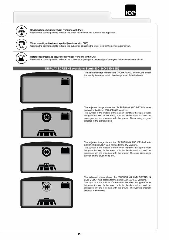
Water quantity adjustment symbol (versions with CDS):Used on the control panel to indicate the button for adjusting the water level in the device water circuit.
Brush head command symbol (versions with PM):Used on the control panel to indicate the brush head command button of the appliance.
Detergent percentage adjustment symbol (versions with CDS):Used on the control panel to indicate the button for adjusting the percentage of detergent in the device water circuit.
The adjacent image identifies the “WORK PANEL” screen, the icon in the top right corresponds to the charge level of the batteries.
The adjacent image shows the “SCRUBBING AND DRYING” work screen for the Scrub 50O-55D-65D versions.The symbol in the middle of the screen identifies the type of work being carried out. In this case, both the brush head unit and the squeegee unit are in contact with the ground. The working program selected is the standard one.
The adjacent image shows the “SCRUBBING AND DRYING with EXTRA PRESSURE" work screen for the PM versions.The symbol in the middle of the screen identifies the type of work being carried out. In this case, both the brush head unit and the squeegee unit are in contact with the ground. The extra pressure is exerted on the brush head unit.
DISPLAY SCREENS (versions Scrub 50C-50O-55D-65D)
The adjacent image shows the “SCRUBBING AND DRYING IN ECO-MODE” work screen for the Scrub 50O-55D-65D versions.The symbol in the middle of the screen identifies the type of work being carried out. In this case, both the brush head unit and the squeegee unit are in contact with the ground. The working program selected is eco-mode.

16 17
The adjacent image shows the “SCRUBBING ONLY” work screen for the Scrub 50O-55D-65D versions.The symbol in the middle of the screen identifies the type of work being carried out. In this case, only the brush head unit is in contact with the ground. The squeegee unit is in its idle position. The working program selected is the standard one.
The adjacent image shows the “SCRUBBING ONLY” work screen for the PM versions.The symbol in the middle of the screen identifies the type of work being carried out. In this case, only the brush head unit is in contact with the ground. The squeegee unit is in its idle position. The extra pressure is exerted on the brush head unit.
The adjacent image shows the “SCRUBBING AND DRYING IN ECO-MODE” work screen for the Scrub 50C versions.The symbol in the middle of the screen identifies the type of work being carried out. In this case, both the brush head unit and the squeegee unit are in contact with the ground. The working program selected is eco-mode.
The adjacent image shows the “SCRUBBING AND DRYING” work screen for the Scrub 50C versions.The symbol in the middle of the screen identifies the type of work being carried out. In this case, both the brush head unit and the squeegee unit are in contact with the ground. The working program selected is the standard one.
The adjacent image shows the “SCRUBBING AND DRYING IN ECO-MODE with EXTRA PRESSURE" work screen for the PM versions.The symbol in the middle of the screen identifies the type of work being carried out. In this case, both the brush head unit and the squeegee unit are in contact with the ground. The extra pressure is exerted on the brush head unit.

17
The adjacent image shows the “SCRUBBING ONLY” work screen for the Scrub 50C versions.The symbol in the middle of the screen identifies the type of work being carried out. In this case, only the brush head unit is in contact with the ground. The squeegee unit is in its idle position. The working program selected is the standard one.
The adjacent image shows the “DRYING ONLY” work screen.The symbol in the middle of the screen identifies the type of work being carried out. In this case, only the squeegee unit is in contact with the ground. The brush head unit is in its idle position. The working program selected is the standard one.
The drying without scrubbing operation should only be carried out if beforehand the device was used to carry out scrubbing without drying.
The adjacent image shows the “CRITICAL BATTERY CHARGE LEVEL” warning screen.The symbol in the middle of the screen indicates that the battery charge has reached a critical level. The remaining charge is sufficient for completing the drying task before recharging the batteries.
The adjacent image shows the “ECO-MODE DRYING ONLY” work screen.The symbol in the middle of the screen identifies the type of work being carried out. In this case, only the squeegee unit is in contact with the ground. The brush head unit is in its idle position. The working program selected is eco-mode.
The drying without scrubbing operation should only be carried out if beforehand the device was used to carry out scrubbing without drying.
The adjacent image indicates that “REVERSE” movement is being used.The symbol in the middle of the screen indicates that reverse movement is currently being used.

18 19
The adjacent image identifies “EMERGENCY SWITCH ACTIVE”.The symbol in the middle of the screen indicates that currently the emergency button has been activated.
The adjacent image indicates “ELECTRONIC BRAKE DISENGAGED” status.The symbol that appears in the middle of the screen indicates that the appliance's electric brake is not currently engaged.
The adjacent image indicates the “BRUSH UNCOUPLING” for the BT versions.The symbol in the middle of the screen indicates the activation of the sequence for releasing the brush from the brush-holder plate on the brush head.
19
PREP
AR
ING
TH
E A
PPLI
AN
CE
19
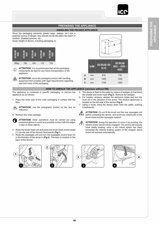
PREPARING THE APPLIANCEHANDLING THE PACKED APPLIANCE
Since the packaging elements (plastic bags, staples, etc.) are a potential source of danger, they should not be left within the reach of children, disabled persons, etc.Gross weight of device, including packaging, is:
HOW TO UNPACK THE APPLIANCE (versions without PM)The appliance is contained in specific packaging, to remove the appliance do as follows:
1. Place the lower part of the outer packaging in contact with the floor.
ATTENTION: use the pictograms printed on the box as reference.
2. Remove the outer package.
ATTENTION: these operations must be carried out using protective gloves to avoid any possible contact with the edges or tips of metal objects.
3. Raise the brush head unit and press the brush head control pedal (1) (on the rear of the device) downwards (Fig.1).
4. Raise the squeegee unit and turn the squeegee control lever (2) in the direction of the arrow in (Fig.2). The lever is located on the back of the device.
5. The device is fixed to the pallet by means of wedges (3) that block the wheels and brush head (Fig.3). Remove the wedges.
6. For traction versions, release the electronic brake and turn the lever (4) in the direction of the arrow. The traction gearmotor is located on the left side of the device (Fig.4).
7. Using a chute, bring the device down from the pallet, pushing it backwards.
ATTENTION: Do not fit the brush and the rear squeegee unit before unloading the device, and avoid any violent jolts to the brush head and the squeegee support.
ATTENTION: during the operation to move it by pushing, the electric brake should not be engaged. The device will anyway have safety braking, once a set critical speed has been exceeded the internal braking system of the chopper circuit board will activate automatically.
ATTENTION: it is recommended that all the packaging components be kept for any future transportation of the appliance.
ATTENTION: move the packaged product with handling equipment that complies with legal requirements regarding size and mass of the packaging.
1
2
21 4
4
3
3
U/M SCRUB 50 D-O
SCRUB 50C - 55D -
65D
A mm 610 730
B mm 1250 1330
C mm 1135 1220
SCR
UB
50
D
SCR
UB
50
O
SCR
UB
50
C
SCR
UB
55
D
SCR
UB
65
D
95kg 105 100 112 115

20
PREPA
RIN
G TH
E A
PPLIAN
CE
HOW TO UNPACK THE APPLIANCE (versions with PM)The appliance is contained in specific packaging, to remove the appliance do as follows:
1. Place the lower part of the outer packaging in contact with the floor.
ATTENTION: use the pictograms printed on the box as reference.
2. Remove the outer package.
ATTENTION: these operations must be carried out using protective gloves to avoid any possible contact with the edges or tips of metal objects.
3. Check that the appliance is off, if not, set the main switch (1) to “0”, turning the key (2) a quarter of a turn to the left (Fig.1). Remove the key from the instrument panel.
4. Grip the handle (3) on the left side of the recovery tank (Fig.2) and turn the tank as far as it will go, until it reaches the maintenance position (Fig.3).
5. Connect the battery hopper connector (4) to the connector of the general system (5) (Fig. 4).
ATTENTION: This process must be carried out by qualified personnel.
6. Grip the handle (3) on the left side of the recovery tank and turn the tank until it reaches the work position (Fig.5).
7. The device is fixed to the pallet by means of wedges (6) that block the wheels and brush head (Fig.6). Remove the wedges.
8. Start the appliance, turn the main switch (1) to "I", making a quarter turn to the right with the key (2) Fig.7)).
9. Lift the brush head unit, press the “BRUSH HEAD COMMAND” button (7) on the control panel (Fig.8).
10. Raise the squeegee unit and turn the squeegee control lever (8) in the direction of the arrow in (Fig.9). The lever is located on the back of the device.
11. Press the “REVERSE MOVEMENT ACTIVATION - DEACTIVATION” button (9) on the control panel (Fig.10).
ATTENTION: As soon as you press the button (9) on the control panel (Fig.10), the control display will show the “REVERSE” screen (Fig.11).
12. Engage the dead man's levers (10) on the handlebars (Fig.12) to start moving the appliance in reverse mode.
13. Using a chute, bring the device down from the pallet, pushing it backwards.
ATTENTION: Do not fit the brush and the rear squeegee unit before unloading the device, and avoid any violent jolts to the brush head and the squeegee support.
2
2
1
5
4
3
1 43
5
3
6
62 7
1
7 8
8
9
109
1210
11

21
PREP
AR
ING
TH
E A
PPLI
AN
CE14. Turn off the appliance, turning the main machine switch (1) to "0",
and turn the key (2) a quarter turn to the left ( Fig.1). Remove the key from the instrument panel.
15. Grip the handle (3) on the left side of the recovery tank (Fig.2) and turn the tank as far as it will go, until it reaches the maintenance position (Fig.3).
16. Disconnect the battery hopper connector (4) from the connector of the general system (5) Fig.13).
ATTENTION: This process must be carried out by qualified personnel.
17. Grip the handle (3) on the left side of the recovery tank and turn the tank until it reaches the work position (Fig.5).
HOW TO TRANSPORT THE APPLIANCETo transport the machine, proceed as follows:
1. Check that the solution tank and recovery tank are empty. If they are not, empty them (read the paragraph “CHECKING AND CLEANING THE RECOVERY TANK” or read the paragraph“CHECKING AND CLEANING THE SOLUTION TANK”).
2. For Scrub 50D versions, make sure the device is switched off. If it isn't, press the main switch (1) on the back of the device (Fig.1).
ATTENTION: in Scrub 50D versions, the main switch (1) is in the idle position when the LED inside it is OFF and the activation symbol is not visible.
3. For traction versions, make sure the device is switched off. If it isn't, bring the main switch (2) to the “0” position by making a quarter turn to the left with the key (3) (Fig.2). Remove the key from the instrument panel.
4. Grip the handle (4) on the left side of the recovery tank (Fig.3) and turn the tank as far as it will go, until it reaches the maintenance position (Fig.4).
5. Disconnect the connector of the general system (5) from the connector of the batteries (6)Fig.5).
ATTENTION: This process must be carried out by qualified personnel.
6. Grip the handle on the left side of the recovery tank and turn the tank until it reaches the work position (Fig.6).
7. For traction versions, release the electronic brake and turn the lever (7) in the direction of the arrow. The traction gearmotor is located on the left side of the device (Fig.7).
8. Using a chute, slide the machine onto the pallet.9. For traction versions, engage the electronic brake and turn the
lever (7) in the direction of the arrow. The traction gearmotor is located on the left side of the device (Fig.8).
10. Secure the device to the pallet using the wedges.
ATTENTION: for transportation without a pallet, secure the device according to the directives in force in the country of use so that it does not slide or tip over.
5
4
13
3
3 7
1 3
2
6
5
4
4
1 2
5
OFF
4
8
7 7

22
PREPA
RIN
G TH
E A
PPLIAN
CE
COMPONENT POSITIONINGThe basic components of the appliance are as follows:
1. Knob for adjusting the work speed (50D versions) (Fig.1).2. Recovery tank outlet pipe (Fig.2).3. Handle for raising the recovery tank (Fig.2).
4. Solution tank cap/measuring device (Fig.3).5. Tube for quick filling of the solution tank (Fig.3).6. Tube for solution tank level/drainage (Fig.4).7. Handle for raising the squeegee unit (Fig.4).8. Rod for adjusting the detergent solution flow (Fig.4).
9. Tap control lever (Fig.5).10. Squeegee unit vacuum hose (Fig.5).11. Brush head control pedal (Fig.6).12. Solution tank cap/filter (Fig.6).13. Hour meter display (50D versions) (Fig.7).14. Battery charge level display (50D versions) (Fig.7).15. Button for switching brush head gearmotor ON and OFF (50D
versions) (Fig.7).16. Button for switching vacuum motor ON and OFF (50D versions)
(Fig.7).17. Button for switching water system solenoid valve ON and OFF
(50D versions) (Fig.7).18. Dead man's lever (Fig.7).19. Handlebars (Fig.7).20. Main switch (50D versions) (Fig.7).21. Control display (traction versions) (Fig.8).
22. ECO-MODE program selection button (traction versions) (Fig.8).23. Button for adjusting the water flow in the device water system
(valid only for traction versions with CDS) (Fig.8).24. Button for enabling or disabling reverse mode (traction versions)
(Fig.8).25. Brush uncoupling button (traction versions) (Fig.8).26. Button for adjusting the detergent solution percentage in the
device water system (valid only for traction versions with CDS) (Fig.8).
27. Knob for adjusting the operation control potentiometer (traction versions) (Fig.8).
28. Dead man's lever (Fig.8).29. Handlebars (Fig.8).30. Key switch for controlling the main system (traction versions)
(Fig.8).31. Emergency button (BT versions) (Fig.8).
32. Recovery tank cover (Fig.9).33. Storage compartment (Fig.9).34. Cap for battery charger socket (battery charger versions only)
(Fig.10).35. Battery charge LED display (battery charger versions only)
(Fig.10).36. Electronic brake lever (traction versions only) (Fig.11).
37. Brush head carter guard (50C version) (Fig.12).38. Right side splash guard retainer knob (50C version) (Fig.12).39. Right side splash guard (50C version) (Fig.12).40. Front brush hub (50C version) (Fig.12).41. Rear brush hub (50C version) (Fig.12).42. Debris hopper (50C version) (Fig.12).43. Brush head control button (versions with PM) (Fig.8).
3
43
1 52
21 4
7
86
33
32 35 36
42
38 37
40
41
39
34
10 11 129
7 8
10
912
11
15
14 13
17
27
16
24
212243
30 29
23
31
1820
19
25
26
2865

23
PREP
AR
ING
TH
E A
PPLI
AN
CEAPPLIANCE SAFETY
The stages for making the appliance safe, and thereby allowing all the operations to be carried out in complete safety, are as follows:
1. For traction versions, make sure the electronic brake is engaged by turning the lever (1) in the rear right part of the machine counter-clockwise (Fig.1).
2. Check that the recovery tank is empty, if not, empty it with the tube (2) on the left side of the appliance (Fig.2) (read the paragraph “CHECKING AND CLEANING THE RECOVERY TANK”).
ATTENTION: The tanks should be emptied in the place used for draining dirty water.
ATTENTION: the place designated for this operation must comply with current environmental protection regulations.
3. For 50D versions, make sure the device is switched off. If it isn't, press the main switch (3) on the back of the device (Fig.3).
ATTENTION: in 50D versions, the main switch (3) is in the idle position when the LED inside it is OFF and the activation symbol is not visible.
4. For versions with PM, start the appliance, turn the main switch (4) to "I", making a quarter turn to the right with the key (5) Fig.4)).
5. Lower the brush head unit, press the “BRUSH HEAD COMMAND” button (6) on the control panel (Fig.5).
6. For traction and PM versions, switch off the machine by bringing the main switch (4) to "0" and making a quarter turn to the left with the key (5) Fig.6)). Remove the key from the instrument panel.
7. For versions without PM, bring the brush head into contact with the floor, using the brush head control pedal (7) (Fig.7).
8. Bring the squeegee into contact with the floor, turn the squeegee control lever (8) counter-clockwise (Fig.8).
9. Grip the handle (9) on the left side of the recovery tank (Fig.9) and turn the tank as far as it will go, until it reaches the maintenance position (Fig.10).
10. Disconnect the connector of the general system (10) from the connector of the batteries (11) (Fig.11).
ATTENTION: This process must be carried out by qualified personnel.
11. Grip the handle on the left side of the recovery tank and turn the tank until it reaches the work position (Fig.12).
TYPE OF BATTERY TO BE USEDPower to the machine must be supplied by two sealed traction batteries with gas recombination or gel technology.The batteries must meet the requirements laid out in the norms: CEI EN 60254-1:2005-12 (CEI 21-5) + CEI EN 60254-2:2008-06 (CEI 21-7). For a good operating performance, we suggest the use of two 12V MFP 77 Ah/C5 batteries.
BATTERY MAINTENANCE AND DISPOSALFor maintenance and recharging, respect the instructions provided by the battery manufacturer. When the battery reaches the end of its working life, it must be disconnected by expert, trained personnel then removed from the battery compartment with the aid of suitable lifting devices.
ATTENTION: dead batteries are classified as dangerous waste and as such must be delivered to an authorised body for disposal.
1 2
1
2
5
5
3
4
4
3
6
4
OFF
9
109 11
11
10
12
87
87
6
5

24
PREPA
RIN
G TH
E A
PPLIAN
CE
5. Grip the handle (6) on the left side of the recovery tank (Fig.5) and turn the tank as far as it will go, until it reaches the maintenance position (Fig.6).
ATTENTION: for battery maintenance and daily recharging, you must fully respect the indications provided by the manufacturer or retailer.
ATTENTION: all installation and maintenance operations must be carried out by specialised personnel.
ATTENTION: before installing the battery, clean the battery compartment. Check that the connectors on the cables supplied are functioning correctly.
ATTENTION: check that the characteristics of the battery that you are looking to use are appropriate for the type of work to
be performed. Check the battery charge and the condition of the contacts on the battery.
ATTENTION: you are advised to only lift and move the batteries with lifting and transportation means suitable for the specific weight and size
ATTENTION: the lifting hooks must not damage the blocks, connectors or cables.
ATTENTION: before inserting the batteries, remember to cover the terminals with a little grease to protect them against external corrosion.
6. House the batteries in the compartment, positioning the poles “+” and “-“ opposite each other (Fig.7).
INSERTING BATTERIES INTO THE DEVICEThe batteries must be housed in the special compartment beneath the recovery tank and should be handled using lifting equipment that is suitable in terms of both weight and its coupling system.
ATTENTION: make sure that you comply with the accident prevention regulations in force in the country where you work or with DIN EN 50272-3 and DIN EN 50110-1, before any handling of the batteries.
ATTENTION: to prevent an accidental short circuit use insulated tools to connect the batteries, and do not place or drop metal objects on the battery. Remove rings, watches and any clothing with metal parts that may come into contact with the battery terminals.
The various phases for inserting the batteries in the battery compartment are as follows:
1. For traction versions, make sure the electronic brake is engaged by turning the lever (1) in the rear right part of the machine counter-clockwise (Fig.1).
2. Check that the recovery tank is empty, if not, empty it with the tube (2) on the left side of the appliance (Fig.2) (read the paragraph “CHECKING AND CLEANING THE RECOVERY TANK”).
ATTENTION: The tanks should be emptied in the place used for draining dirty water.
ATTENTION: the place designated for this operation must comply with current environmental protection regulations.
3. For 50D versions, make sure the device is switched off. If it isn't, press the main switch (3) on the back of the device (Fig.3).
ATTENTION: in 50D versions, the main switch (3) is in the idle position when the LED inside it is OFF and the activation symbol is not visible.
4. For traction versions, make sure the device is switched off. If it isn't, set the main switch (4) to “0” by making a quarter turn to the left with the key (5) (Fig.4). Remove the key from the instrument panel.
765
1 2
1
2
6
5
3
4
3 4
OFF

25
PREP
AR
ING
TH
E A
PPLI
AN
CECONNECTING BATTERIES TO THE SYSTEM OF THE APPLIANCE
The batteries should be connected so as to obtain a total voltage of 24V.
ATTENTION: it is recommended that all installation and maintenance operations be carried out by expert personnel, trained at the specialised assistance centre.
ATTENTION: to prevent an accidental short circuit use insulated tools to connect the batteries, and do not place or drop metal objects on the battery. Remove rings, watches and any clothing with metal parts that may come into contact with the battery terminals.
The various phases for inserting the batteries in the battery compartment are as follows:
1. Using the jumper cable supplied (1), connect the “+” and “-“ poles of the batteries in series (Fig.1).
2. Connect the battery connector cable (2) to the “+” and “-“ poles to obtain a voltage of 24V on the terminals (Fig.2).
3. Connect the battery connector (2) to the electric system connector (3) (Fig.3).
RECHARGING THE BATTERIES (versions without built-in battery charger)The battery must be charged prior to the first use, and when it doesn't provide enough power for tasks that could formerly be performed without difficulty.
ATTENTION: to avoid any permanent damage to the batteries, it is essential to avoid their complete discharge; begin recharging them within a few minutes of noting the "discharged batteries" signal.
ATTENTION: never leave the batteries completely discharged, even if the device is not being used.
To recharge the batteries without the built-in battery charger, proceed as follows:
1. Bring the appliance to the zone where the batteries are charged.2. Take all necessary steps to ensure that the device is in a safe
condition (see "MACHINE SAFETY ’”).
ATTENTION: park the appliance in an enclosed place, on a flat surface; near the appliance there must be no objects that could either damage it, or be damaged through contact with it.
ATTENTION: the room used to recharge the batteries must be adequately ventilated to prevent the accumulation of gases that leak from batteries.
3. Grip the handle (1) on the left side of the recovery tank (Fig.1).4. Turn the recovery tank up to the end stop, maintenance position
(Fig.2).5. Disconnect the electric system connector (3) from the battery
connector (2) (Fig.3).
ATTENTION: the following operations must be carried out by qualified personnel. An incorrect connection of the connector may cause a malfunction of the device.
6. Connect the external battery charger cable connector (4) to the battery connector (2) (Fig.4).
ATTENTION: the coupling connector of the battery charger is consigned inside the bag containing this instruction booklet, and must be assembled on the cables of the battery charger as indicated in the instructions.
ATTENTION: before connecting the batteries to the battery charger, make sure it is suitable for the batteries used.
ATTENTION: carefully read the use and maintenance instructions of the battery charger that is used for charging.
ATTENTION: keep the recovery tank open for the duration of the battery recharging cycle to allow gas fumes to escape.
7. When the recharge cycle is complete, disconnect the battery charger cable connector (4) from the battery connector (2) (Fig.5).
8. Connect the electric system connector (3) to the battery connector (2) (Fig.6).
9. Grip the handle (1) on the side of the recovery tank (Fig.7).10. Turn the recovery tank as far as it will go, to the work position
(Fig.8).
3
1 2 3 2
21
14
2
3
2
2 41 3

26
PREPA
RIN
G TH
E A
PPLIAN
CE
RECHARGING THE BATTERIES (versions with built-in battery charger)The battery must be charged prior to the first use, and when it doesn't provide enough power for tasks that could formerly be performed without difficulty.
ATTENTION: to avoid any permanent damage to the batteries, it is essential to avoid their complete discharge; begin recharging them within a few minutes of noting the "discharged batteries" signal.
ATTENTION: never leave the batteries completely discharged, even if the device is not being used.
To recharge the batteries with the on-board battery charger proceed as follows:
1. Bring the appliance to the zone where the batteries are charged.2. Take all necessary steps to ensure that the device is in a safe
condition (see “MACHINE SAFETY”).
ATTENTION: park the appliance in an enclosed place, on a flat surface; near the appliance there must be no objects that
could either damage it, or be damaged through contact with it.
ATTENTION: the room used to recharge the batteries must be adequately ventilated to prevent the accumulation of gases that leak from batteries.
3. Grip the handle (1) on the left side of the recovery tank (Fig.1).4. Turn the recovery tank up to the end stop, maintenance position
(Fig.2).
ATTENTION: the following operations must be carried out by qualified personnel. An incorrect connection of the connector may cause a malfunction of the device.
ATTENTION: carefully read the use and maintenance instructions of the battery charger that is used for charging.
5. Connect the battery connector (2) to the electric system connector (3) (Fig.3).
6. Remove the cap (4) from the battery charger socket (Fig.4).
ATTENTION: before connecting the batteries to the battery charger, make sure it is suitable for the batteries used.
ATTENTION: before inserting the battery charger power cable in the socket (5), make sure there is no condensate or other types of liquid (Fig.5).
ATTENTION: the charger power cable is delivered inside the bag containing this instruction booklet.
7. Connect the connector of the battery charger power cable (6) to the socket in the charger itself (Fig.6).
8. Plug the battery charger cable into the mains socket.
ATTENTION: keep the recovery tank open for the duration of the battery recharging cycle to allow gas fumes to escape.
9. When the recharge cycle is complete, disconnect the battery charger cable from the mains.
10. Disconnect the connector of the battery charger power cable (6) from the socket in the charger itself (Fig.7).
11. Insert the cap (4) on the battery charger socket (Fig.8).12. Grip the handle (1) on the side of the recovery tank (Fig.9).13. Turn the recovery tank as far as it will go, to the work position
(Fig.10).
13
2
4
2
86 75
14
4
3
22 4
8
31
56 6
6 75

27
PREP
AR
ING
TH
E A
PPLI
AN
CE
HOUR METER (50D versions)
BATTERY CHARGE LEVEL INDICATOR (50D versions)
HOUR METER (traction versions)
The device's control panel contains the hour meter display (1), which shows the total usage time (Fig.1). The numbers before the "." symbol identify hours, while the number that follows it indicates hour decimals (an hour decimal corresponds to six minutes). The flashing “:” symbol indicates that the hour meter is counting the appliance's operating time.
The device's control panel contains the control display, which shows the total usage time. The numbers before the letter “h” identify the hours, while the numbers before the letter “m” identify the tenths of an hour (a tenth of an hour corresponds to six minutes). The flashing “:” symbol indicates that the hour meter is counting the appliance's operating time.
The instrument panel contains the display (3) indicating the battery charge status (Fig.3). The battery charge level is represented by five numbers from 0 to 4, where 0 corresponds to a critical charge level and 4 corresponds to a fully charged battery.
ATTENTION: a few seconds after the battery charge reaches the critical level, the brush motor switches off automatically. With the remaining charge it is possible to complete the drying process before starting the recharge.
The device instrument panel contains the control display. At the top right of the work screen, there is a graphic symbol (01) representing the battery charge level indicator (Fig.1). The indicator is composed of 5 charge levels, each of which represents about 20% of residual charge. With a residual charge of 20%, the graphic symbol starts to flash. After a few seconds it appears in larger dimensions in the middle of the screen (Fig.2); at this point, you must take the machine to the designated recharging place.
ATTENTION: a few seconds after the battery charge level reaches 20%, the brush motor switches off automatically. With the remaining charge it is still possible, however, to complete the drying process before recharging
ATTENTION: a few seconds after the battery charge level reaches 10%, the vacuum motor switches off automatically. The remaining charge is sufficient for moving the appliance to the designated recharging place
BATTERY CHARGE LEVEL INDICATOR (traction versions)
1
109
3
1
2
1
2
3
1 2
1

28
PREPA
RIN
G TH
E A
PPLIAN
CE
INSTALLING THE BRUSH (SCRUB 50D)
BRUSH ASSEMBLY (SCRUB 55-65 without PM)
For packaging reasons, the brush is supplied disassembled from the device. To assemble it on the brush head unit, proceed as follows:
1. Take all necessary steps to ensure that the device is in a safe condition (see “MACHINE SAFETY”).
2. Raise the brush head unit off the floor and press the brush head control pedal (1) on the rear of the device (Fig.1).
ATTENTION: these operations must be carried out using protective gloves to avoid any possible contact with the edges or tips of metal objects.
For packaging reasons, the brush is supplied disassembled from the device. To assemble it on the brush head unit, proceed as follows:
1. Take all necessary steps to ensure that the device is in a safe condition (see "MACHINE SAFETY ’”).
2. Position yourself at the rear of the appliance.3. Lower the brush head unit by pressing the brush head control
pedal (1) on the back of the appliance (Fig.1).4. Position yourself at the front of the appliance.5. If the splash guard carters (2) are present, remove them (Fig.2)
and lay them gently on the ground.6. Position yourself at the rear of the appliance.7. Raise the brush head unit off the floor and press the brush head
control pedal (1) on the rear of the device (Fig.3).
3. If the splash guard is present, release the retainer spring (2) on the brush head splash guards (Fig.2).
4. Remove the retainer blade (3) and the splash guard (4) (Fig.3).5. With the brush head UP, insert the brush in the plate housing
underneath the brush head, turning it until the three buttons engage with the niches on the plate itself. Turn until the pin is pushed towards the coupling spring and is locked into place. The photo (Fig.4) shows the rotation direction for brush coupling.
6. Replace the splash guard, inserting first the rear left part and then the right part. Remember to fix it to the brush head using the retainer blade.
7. Fix the retainer blade to the brush head with the aid of the spring.
8. With the brush head UP, insert the brush in the plate housing underneath the brush head, turning it until the three buttons engage with the niches on the plate itself.
9. Press the brush-holder plate latch (3) and simultaneously rotate the brush (4) according to the direction indicated in the image (Fig.4).
ATTENTION: The image Fig.4 shows the rotation direction of the left brush.
10. When the brush rotation is prevented, turn until the button on the brush is engaged in the coupling spring, present on the brush-holder plate.
11. Reassemble the brush head splash guard carters.
INSTALLING THE BRUSH HEAD SPLASH GUARD (SCRUB 50D)For packaging reasons, the brush head splash guard is supplied disassembled from the device, and must be assembled on the brush head unit as follows:
1. Take all necessary steps to ensure that the device is in a safe condition (see "MACHINE SAFETY ’”).
2. Raise the brush head unit off the floor and press the brush head control pedal (1) on the rear of the device (Fig.1).
ATTENTION: these operations must be carried out using
protective gloves to avoid any possible contact with the edges or tips of metal objects.
3. Release the retainer spring (2) on the brush head splash guards (Fig.2).
4. Remove the retainer blade (3) (Fig.3).5. Fit the splash guard (Fig.4), inserting first the left part and then
the right part. Remember to fix it to the brush head using the retainer blade.
6. Fix the retainer blade to the brush head with the aid of the spring.
1
2
3
2
4
1
3
1
11
2
3
42 41
31
3
2
2 4
1
1

29
PREP
AR
ING
TH
E A
PPLI
AN
CEASSEMBLING THE BRUSH HEAD SPLASH GUARD (SCRUB 55-65)
For packaging reasons, the brush head splash guard is supplied disassembled from the device, and must be assembled on the brush head unit as follows:
1. Take all necessary steps to ensure that the device is in a safe condition (see "MACHINE SAFETY ’”).
ATTENTION: these operations must be carried out using protective gloves to avoid any possible contact with the edges or tips of metal objects.
2. Position yourself at the front of the appliance.3. Insert the pins (1) present on the left splash guard (2) (Fig.1) into
the holes (3) present in the brush head body (4) (Fig.2).4. Repeat the same operation for the right splash guard also.
BRUSH ASSEMBLY (SCRUB 55-65 with PM)For packaging reasons, the brush is supplied disassembled from the device. To assemble it on the brush head unit, proceed as follows:
1. Check that the electronic brake is engaged, turn the lever (1) in the rear right part of the machine anti-clockwise (Fig.1).
2. Check that the recovery tank is empty, if not, empty it with the tube (2) on the left side of the appliance (Fig.2) (read the paragraph “CHECKING AND CLEANING THE RECOVERY TANK”).
ATTENTION: The tanks should be emptied in the place used for draining dirty water.
ATTENTION: the place designated for this operation must comply with current environmental protection regulations.
3. Start the appliance, turn the main switch (3) to "I", making a quarter turn to the right with the key (4) Fig.3)).
4. Lower the brush head unit, press the “BRUSH HEAD COMMAND” button (5) on the control panel (Fig.4).
5. As soon as the brush head is in contact with the floor, turn off the appliance, turn the main switch (3) to "0", turning the key (4) a quarter turn to the left ( Fig.5). Remove the key from the instrument panel.
6. Position yourself at the front of the appliance.7. Remove the splash guard carters (6), remove them (Fig.6) and
lay them gently on the ground.8. Position yourself at the rear of the appliance.9. Insert the key (4) into the main switch (3).
10. Start the appliance, turn the main switch (3) to "I", making a quarter turn to the right with the key (4) Fig.3)).
11. Lift the brush head unit, press the “BRUSH HEAD COMMAND” button (5) on the control panel (Fig.4).
12. Turn off the appliance, turning the main machine switch (3) to "0", turning the key (4) a quarter turn to the left ( Fig.5). Remove the key from the instrument panel.
13. Grip the handle (7) on the left side of the recovery tank (Fig.7) and turn the tank as far as it will go, until it reaches the maintenance position (Fig.8).
1 4
2 321
1 2
1
2
4
3
3
5
4
4
3 6
5 6
7
87

30
PREPA
RIN
G TH
E A
PPLIAN
CE
14. Disconnect the connector of the general system (8) from the connector of the batteries (9) (Fig.9).
ATTENTION: This process must be carried out by qualified personnel.
15. Grip the handle (7) on the left side of the recovery tank and turn the tank until it reaches the work position (Fig.10).
16. With the brush head UP, insert the brush in the plate housing underneath the brush head, turning it until the three buttons engage with the niches on the plate itself.
17. Press the brush-holder plate latch (10) and simultaneously rotate the brush (11) according to the direction indicated in the image (Fig.11).
ATTENTION: The image Fig.11 shows the rotation direction of the left brush.
18. When the brush rotation is prevented, turn until the button on the brush is engaged in the coupling spring, present on the brush-holder plate.
19. Grip the handle (7) on the left side of the recovery tank (Fig.7) and turn the tank as far as it will go, until it reaches the maintenance position (Fig.8).
20. Connect the connector of the general system (8) from the connector of the batteries (9) (Fig.12).
ATTENTION: This process must be carried out by qualified personnel.
21. Grip the handle (7) on the left side of the recovery tank and turn the tank until it reaches the work position (Fig.10).
INSTALLING THE BRUSH (50C versions)For packaging reasons, the brush is supplied disassembled from the device. To assemble it on the brush head unit, proceed as follows:
1. Take all necessary steps to ensure that the device is in a safe condition (see "MACHINE SAFETY ’”).
2. Raise the brush head unit off the floor and press the brush head control pedal (1) on the rear of the device (Fig.1).
ATTENTION: these operations must be carried out using protective gloves to avoid any possible contact with the edges or tips of metal objects.
3. Position yourself on the right-hand side of the appliance.4. Loosen the retainer knob (2) (Fig.2).5. Remove the right side splash guard support (3), taking care to
shift the blade before removing the splash guard support itself (Fig.3).
6. Remove the rear brush guide hub (4) (Fig.4).
7. Insert the rear brush into the tunnel, taking care to properly position the drive pins (5) present on the guide hub (6) in the slits present on the brush (Fig. 5).
8. Insert the hub (4) into the brush, taking care to properly position the drive pins (7) in the slits present on the brush (Fig. 6).
9. Repeat the operations described above for the front brush as well.
ATTENTION: The rear brush (8) (working direction) must always be the blue one (Fig.7).
ATTENTION: The brush bristles are properly positioned if they form a rhombus when viewed from above. The top of the shortest height must be positioned towards the front of the appliance.
10. Repeat the operations in reverse order to reassemble all the parts.
8
9
9
7
1110
8
912
1
1
4
4
2 3
2 3
5
6
7
4 8
6 75
10
11

31
PREP
AR
ING
TH
E A
PPLI
AN
CEASSEMBLING THE SQUEEGEE
For packaging reasons, the squeegee unit is supplied disassembled from the device, and must be assembled on the squeegee support as follows:
1. Take all necessary steps to ensure that the device is in a safe condition (see “MACHINE SAFETY”).
ATTENTION: these operations must be carried out using protective gloves to avoid any possible contact with the edges or tips of metal objects.
2. Make sure the squeegee unit support is raised off the floor. If it isn't, turn the squeegee control lever (1) on the back of the machine in the direction shown by the arrow (Fig.1).
3. Unscrew the knobs (2) in the squeegee unit pre-assembly (Fig.2).4. First insert the left pin (3) on the squeegee body into the left slit
(4) in the squeegee support (Fig.3), making sure that the washer and spring adhere to the top of the squeegee support.
5. Insert the right pin (5) on the squeegee body into the right slit (6) in the squeegee support (Fig.4), making sure that the washer and spring adhere to the top of the squeegee support.
6. Tighten the knobs (2), ensuring that the washer and spring adhere to the top part of the squeegee support (Fig.5).
7. Insert the vacuum tube (7) in the sleeve (8) in the squeegee unit (Fig.6).
ATTENTION: the squeegee has been adjusted beforehand, nevertheless if it is necessary read the section “ADJUSTING THE SQUEEGEE UNIT”.
FILLING THE SOLUTION TANK WITH WATERBefore filling the solution tank, carry out the following steps:
1. Take the machine to the dedicated solution tank filling area.2. Take all necessary steps to ensure that the device is in a safe
condition (see "MACHINE SAFETY’”).3. Check that the solution tank discharge cap (1) is open. If it isn't,
open it (Fig.1).4. Check that the filter plug of the water system (2) at the rear
right part of the machine, has been tightened, and if not turn it clockwise (Fig.2).
The solution tank can be filled with water in three different ways:
• Removing the cap/measuring device (3) and filling the solution tank by means of a rubber hose or a bucket (Fig.3).
• Using the filler hose (4) (Fig.4). This supports the water hose on its own, but be sure to remove the cap/measuring device (3) to allow adequate air venting.
1 3 5
2
4 6
2 41 3
2
8
7
65
1 2
3 4
3
431 2

32
PREPA
RIN
G TH
E A
PPLIAN
CE
• Using the optional system for automatic clean water top-up (5) (Fig.5). This system has a float for avoiding any overflow.
5. Fill with clean water, at a temperature not higher than 50°C and not lower than 10°C. The amount inside the tank can be seen by means of the level tube (6) (Fig.6) on the front left of the seat.
DETERGENT SOLUTIONAfter filling the solution tank with clean water add the liquid detergent to the tank in the concentration and manner indicated on the detergent manufacturer's label. To prevent the formation of an excessive amount of foam that could damage the vacuum motor, use the minimum percentage of detergent required.
ATTENTION: protective gloves should always be worn before handling detergents or acidic or alkaline solutions, to avoid serious injury to the hands.
ATTENTION: always use detergents whose manufacturer's label indicates their suitability for scrubbing machines. Do not use acid or alkaline products or solvents without this indication.
ATTENTION: acid or alkaline maintenance detergent tank be used with pH values between 4 and 10 and that do not contain: oxidising agents, chlorine or bromine, formaldehyde, mineral solvents. The detergents used must be suitable for use with scrubbing machines.
ATTENTION: always use low-foam detergent. To avoid the production of foam, put a minimum quantity of antifoam liquid in the recovery tank before starting to clean. Do not use pure acids.
ATTENTION: to make it easier to measure the detergent on the cap/measuring device, there are two notches indicating the two main detergent percentage quantities that can be used.
65
5 6

33
PREP
AR
ING
TO
W
OR
K
Before beginning to work, it is necessary to:
1. Make sure that the recovery tank is empty, if not, empty it completely (see the paragraph “CHECKING AND CLEANING THE RECOVERY TANK”).
2. Verify that the quantity of detergent solution in the solution tank is suitable for the type of work you wish to carry out, otherwise fill the solution tank (see the paragraph "FILLING THE SOLUTION TANK WITH WATER”). View the level tube (1) in the rear of the machine (Fig.1).
3. Make sure that the state of the squeegee rubbers is suitable for the work, if not, carry out maintenance (see the paragraph “CHECKING AND CLEANING THE SQUEEGEE UNIT”).
4. Check to make sure that the brush's status is suitable for the work to be carried out. If not, perform the necessary maintenance operations (read the paragraph titled “CHECKING AND CLEANING THE BRUSH (B VERSION)”, the paragraph titled
“CHECKING AND CLEANING THE BRUSH (BT VERSION)”, or the paragraph titled “CHECKING AND CLEANING THE BRUSH (BTS VERSION)”).
5. For 50D versions, make sure the device is switched off. If it isn't, press the main switch (2) on the back of the device (Fig.2).
ATTENTION: in 50D versions, the main switch (2) is in the idle position when the LED inside it is OFF and the activation symbol is not visible.
6. For the traction versions, make sure the device is switched off. If it isn't, set the main switch (3) to “0” by turning the key (4) a quarter turn to the left (Fig.3). Remove the key from the instrument panel.
7. Grip the handle (5) on the left side of the recovery tank (Fig.4) and turn the tank as far as it will go, until it reaches the maintenance position (Fig.5).
PREPARING TO WORK
8. Connect the battery connector (7) to the main system connector (6) (Fig.6).
ATTENTION: This process must be carried out by qualified personnel.
9. Grip the handle (5) on the left side of the recovery tank (Fig.7).10. Turn the recovery tank as far as it will go, to the work position
(Fig.8).
11. For the traction versions, make sure the electronic brake is engaged. If it isn't, turn the lever (8) in the direction indicated by the arrow. The traction gearmotor is located on the left side of the device (Fig.9).
12. Make sure the water tap is fully open; the water adjustment knob (9) should be completely down (Fig.10).
13. Check that the solution tank discharge cap (10) is closed. If it isn't, open it (Fig.11).
1
1
6
10
7
6
9
4
2
3
2 3
OFF
5
4
5
5
87
9
8
1110

34
WO
RK
STARTING WORK (50D versions)To start working, do as follows:
1. Make all the checks listed in “PREPARING TO WORK”.2. Get in the driving seat, behind the machine.
3. Press the main system control button (1) so it is in the “work” position (Fig.1).
ATTENTION: when the main system control button is functioning, the LED inside it is activated.
WORK
SCRUBBING AND DRYING (50D versions)To carry out “SCRUBBING AND DRYING” tasks, proceed as follows:
1. Make all the checks indicated in “STARTING WORK (B VERSION)”.
2. Lower the brush head unit by pressing the brush head control pedal (1) on the back of the appliance (Fig.1).
3. Activate the brush head gearmotor using the brush control switch (2) (Fig.2).
4. Lower the squeegee unit by means of the lever (3) on the back of the appliance (Fig.3).
5. By activating the dead man's lever (4), the machine will start to move (Fig.4).
6. Activate the vacuum motor by pressing the relative switch (5) on the control panel (Fig.5).
7. Activate the supply of detergent solution by pressing the switch (6) on the control panel (Fig.6).
8. Check the detergent solution tap is fully open. If it isn't, turn the lever (7) on the back of the appliance (Fig.7).
9. During the first few metres, check that the detergent solution is suitable for the work to be carried out. If it isn't, make the necessary changes after reading the “ADJUSTING THE DETERGENT SOLUTION (VERSIONS WITHOUT CDS)” paragraph.
The appliance will now begin to work with full efficiency until the battery is flat or until the detergent solution has finished. During the first few metres, check that there is sufficient solution and that the squeegee is drying correctly.
ATTENTION: if during the scrubbing - drying operation the dead man's lever is released, the brush motor and the solenoid valve will stop working, the vacuum motor will continue to work for a few seconds to ensure all the liquid in the vacuum hose is sucked up.
ATTENTION: when filling the solution tank, it is good practice to empty the recovery tank using the special drainage hose.
ATTENTION: by pulling the detergent solution flow adjustment knob downwards, the amount of solution in the water system will increase (Fig.7).
1
1
ON
1
4
7
2
5 6
4
1 4
7
2
5 6
3

35
WO
RK
SCRUBBING WITHOUT DRYING (50D versions)To carry out “SCRUBBING WITHOUT DRYING” tasks, proceed as follows:
1. Make all the checks indicated in “STARTING WORK (B VERSION)”.
2. Lower the brush head unit by pressing the brush head control pedal (1) on the back of the appliance (Fig.1).
3. Activate the brush head gearmotor using the brush control switch (2) (Fig.2).
4. By activating the dead man's lever (3), the machine will start to move (Fig.3).
5. Activate the supply of detergent solution by pressing the switch (4) on the control panel (Fig.4).
6. Check the detergent solution tap is fully open. If it isn't, turn the lever (5) on the back of the appliance (Fig.5).
DRYING (50D versions)To carry out “DRYING” tasks, proceed as follows:
1. Make all the checks indicated in “STARTING WORK (B VERSION)”.
2. Lower the squeegee unit by means of the lever (1) on the back of the appliance (Fig.1).
3. By activating the dead man's lever (2), the machine will start to move (Fig.2).
4. Activate the vacuum motor by pressing the relevant switch (3) on the control panel (Fig.3).
The machine will now work at its maximum efficiency level until the batteries run down.
ATTENTION: if the dead man's lever is released during the drying operation, the vacuum motor will continue working for another few seconds so that all the liquid in the vacuum hose can be removed.
7. During the first few metres, check that the detergent solution is suitable for the work to be carried out. If it isn't, make the necessary changes after reading the “ADJUSTING THE DETERGENT SOLUTION (VERSIONS WITHOUT CDS)” paragraph.
The appliance will now begin to work with full efficiency until the battery is flat or until the detergent solution has finished. During the first few metres, check that there is sufficient solution.
ATTENTION: if the dead man's lever is released during the scrubbing and drying operation, the brush motor and solenoid valve will stop working. To resume work, just press the dead man's levers.
ATTENTION: by pulling the detergent solution flow adjustment knob downwards, the amount of solution in the water system will increase (Fig.5).
The drying without scrubbing operation should only be carried out if beforehand the device was used to carry out scrubbing without drying.
1
3
2 4
1 32 4
2
5
31
2
5
31

36
WO
RK
STARTING THE WORK ACTIVITIES (traction version)To start working, do as follows:
1. Make all the checks listed in “PREPARING TO WORK”.2. Get in the driving seat, behind the machine.3. Bring the main switch (1) to "I", making a quarter turn to the right
with the key (2) Fig.1)). 4. When the display comes on, three screens appear in sequence.
• The first screen displayed indicates the name of the machine.• The second screen shows the machine programming
characteristics.• The third screen displays the work panel (Fig.2).
ATTENTION: The symbol in the top right indicates the charge level of the batteries.
5. Check that the potentiometer knob (3) is set to minimum. If it isn't, turn it completely counter-clockwise (Fig.3).
SCRUBBING AND DRYING (traction version)
To carry out “SCRUBBING AND DRYING” tasks, proceed as follows:
1. Make all the checks indicated in “STARTING WORK (BT VERSION)”.
2. For traction version, lower the brush head unit by pressing the brush head control pedal (1) on the back of the appliance (Fig.1).
3. For the PM versions, lower the brush head unit, press the “BRUSH HEAD COMMAND” button (2) on the control panel (Fig.2).
ATTENTION: As soon as the brush head unit is removed from the rest position the control display shows the symbol (3) (Fig.3).
4. Lower the squeegee unit using the lever (4) on the back of the appliance (Fig.4).
ATTENTION: As soon as the squeegee unit is removed from the rest position the control display shows the symbol (5) (Fig.5).
ATTENTION: When both symbols (3) and (5) appear in the control display it means that “SCRUBBING WITH DRYING” is being carried out (Fig.5).
5. Pull the knob (6) down and adjust the amount of solution desired (Fig.6).
ATTENTION: by pulling the detergent solution flow adjustment knob downwards, the amount of solution in the water system will increase (Fig.6).
6. Use the dead man's levers (7) on the instrument panel (Fig.7).
ATTENTION: The appliance has two forward speeds. By pushing the dead man's levers beyond the first CLICK the “SLOW” speed is activated, continuing to push the levers beyond the second CLICK the “FAST” speed is activated.
7. Set the required forward speed by turning the knob (8) gradually to the right (Fig.8).
ATTENTION: For adjustments to the forward speed read the paragraph “ADJUSTING THE FORWARD SPEED (BT VERSIONS)”.
2
1
1
23
3
4
3
4
1 2
1 2
3

37
WO
RK
As soon as the dead man's levers are pressed the traction motor, brush head motor and vacuum motor will start working. As a result, the solenoid valve will also begin working and detergent solution will be delivered to the brush.During the first few metres, check that there is sufficient solution and that the squeegee is drying correctly.The appliance will now begin to work with full efficiency until the battery is flat or until the detergent solution has finished.
ATTENTION: If the dead man's levers are released during the work the appliance will stop moving froward, the brush motor and the solenoid valve will stop working, while the vacuum motor will keep working for a set period of time (factory setting is fifteen seconds) and the symbol (4) will start flashing until the vacuum motor switches off.
ATTENTION: If the appliance has to be switched off with the brush head and the squeegee unit still in contact with the floor, when switched on the work display will show the symbols (3) and (5), indicating that when it was switched off it was carrying out scrubbing with drying (Fig.5).
ATTENTION: If, during work, there is the need to exert more pressure on the brushes (versions with PM) simply press the "BRUSH HEAD COMMAND" button (2) on the control panel (Fig. 2) for more than three seconds, the command display shows the symbol (9) (Fig.9).
ATTENTION: If, during work, there is the need to return to working without exerting more pressure on the brushes (versions with PM) simply press the "BRUSH HEAD COMMAND" button (2) on the control panel (Fig. 2) for more than three seconds, the command display shows the symbol (3) (Fig.5).
SCRUBBING WITHOUT DRYING (traction version)
To carry out “SCRUBBING WITHOUT DRYING” tasks, proceed as follows:
1. Make all the checks indicated in “STARTING WORK (BT VERSION)”.
2. For traction version, lower the brush head unit by pressing the brush head control pedal (1) on the back of the appliance (Fig.1).
3. For the PM versions, lower the brush head unit, press the “BRUSH HEAD COMMAND” button (2) on the control panel (Fig.2).
ATTENTION: As soon as the brush head unit is removed from the rest position the control display shows the symbol (3) (Fig.3).
ATTENTION: When the symbol (3) is shown on the control display it means that the work being carried out is “SCRUBBING WITHOUT DRYING” (Fig.3).
4. Pull the knob (4) down and adjust the amount of solution desired (Fig.4).
ATTENTION: by pulling the detergent solution flow adjustment knob downwards, the amount of solution in the water system will increase (Fig.4).
5. Adjust the dead man's levers (5) on the instrument panel (Fig.5).
ATTENTION: The appliance has two forward speeds. By pushing the dead man's levers beyond the first CLICK the “SLOW” speed is activated, continuing to push the levers beyond the second CLICK the “FAST” speed is activated.
7. Set the required forward speed by turning the knob (6) gradually to the right (Fig.6).
ATTENTION: For adjustments to the forward speed read the paragraph “ADJUSTING THE FORWARD SPEED (BT VERSIONS)”.
3
3
5
5
31 2
1 2
6
4
6
4
5
5
3
7 87 8

38
WO
RK DRYING WITHOUT SCRUBBING (traction version)
To carry out “DRYING WITHOUT SCRUBBING” tasks, proceed as follows:
1. Make all the checks indicated in “STARTING WORK (BT VERSION)”.
2. Lower the squeegee unit by means of the lever (1) on the back of the appliance (Fig.1).
ATTENTION: As soon as the squeegee unit is removed from the rest position the control display shows the symbol (2) (Fig.2).
ATTENTION: When the symbol (2) is shown on the control display it means that the work being carried out is “DRYING WITHOUT SCRUBBING ” (Fig.2).
3. Use the dead man's levers (3) on the instrument panel (Fig.3).
ATTENTION: The appliance has two forward speeds. By pushing the dead man's levers beyond the first CLICK the “SLOW” speed is activated, continuing to push the levers beyond the second CLICK the “FAST” speed is activated.
7. Set the required forward speed by turning the knob (4) gradually to the right (Fig.4).
ATTENTION: For adjustments to the forward speed read the paragraph “ADJUSTING THE FORWARD SPEED (BT VERSIONS)”.
As soon as the dead man's levers are pushed the traction motor will start operating.During the first few metres of work, check that the squeegee is frying properly.The machine will now work at its maximum efficiency level until the batteries run down.
ATTENTION: If the dead man's levers are released during the work the appliance will stop moving froward, the vacuum motor will keep working for a set period of time (factory setting is fifteen seconds) and the symbol (2) will start flashing until the vacuum motor switches off.
ATTENTION: If the appliance has to be switched off with the brush head still in contact with the floor, when switched on the work display will show the symbol (2), indicating that when it was switched off it was carrying out drying without scrubbing (Fig.2).
The drying without scrubbing operation should only be carried out if beforehand the device was used to carry out scrubbing without drying.
As soon as the dead man's levers are pressed the traction motor, brush head motor and vacuum motor will start working. As a result, the solenoid valve will also begin working and detergent solution will be delivered to the brush.During the first few metres, check that there is sufficient for the work that needs to be done.The appliance will now begin to work with full efficiency until the battery is flat or until the detergent solution has finished.
ATTENTION: If the dead man's levers are released during the work the appliance will stop moving froward, the brush motor and the solenoid valve will stop working.
ATTENTION: If the appliance has to be switched off with the brush head still in contact with the floor, when switched on the
work display will show the symbol (3), indicating that when it was switched off it was carrying out scrubbing (Fig.3).
ATTENTION: If, during work, there is the need to exert more pressure on the brushes (versions with PM) simply press the "BRUSH HEAD COMMAND" button (2) on the control panel (Fig. 2) for more than three seconds, the command display shows the symbol (7) (Fig.7).
ATTENTION: If, during work, there is the need to return to working without exerting more pressure on the brushes (versions with PM) simply press the "BRUSH HEAD COMMAND" button (2) on the control panel (Fig. 2) for more than three seconds, the command display shows the symbol (3) (Fig.3).
5 65 6
23 43 4
21
1
77

39
WO
RK
REGULATING THE DETERGENT SOLUTIONTo adjust the amount of detergent solution on the brush, proceed as follows:
1. Fully open the flow from the tap on the back of the appliance by pulling the knob (1) on the back of the appliance downwards (Fig.1).
2. By pushing the dead man's lever (2) the brush motor will start operating and the solenoid valve will distribute detergent solution to the brush (Fig.2).
3. During the first few meters, check that the quantity of solution is enough to wet the floor, but not so much as to come out of the splash guard; the detergent disposal quantity can be adjusted by means of the knob (1) on the appliance's rear.
ATTENTION: If the water system does not work, see the paragraph “CHECKING AND CLEANING THE DETERGENT SOLUTION FILTER-CAP”.
FORWARD SPEED REGULATION (50D versions)
ADJUSTING THE FORWARD SPEED (traction version)
The traction of this appliance is obtained by means of the brush which, working with the right weight distribution, is able to pull the appliance forwards. To regulate the forward speed, proceed as follows:
1. Adjust the forward speed by turning the knob (1) on the front of the appliance (Fig.1).
ATTENTION: turning the knob (1) clockwise tilts the brush forward, thus increasing the friction with the floor and thereby increasing the speed of the appliance.
ATTENTION: turning the knob (1) counter-clockwise tilts the brush backward, thus decreasing the friction with the floor and thereby decreasing the speed of the appliance.
This machine is equipped with electronically controlled traction. To regulate the potentiometer, proceed as follows:
1. Check that the knob (1) is set to minimum, if not, turn it counter-clockwise(Fig.1).
2. Turn the main machine switch (2) to "I", turning the key a quarter turn to the right (Fig.2).
3. Press the dead man's levers (3), positioned under the control handlebar (Fig.3).
4. Adjust the forward speed by gradually turning the knob (1) clockwise (Fig.4).
ATTENTION: the device will not start to move (either forward
2. Get in the driving seat, behind the machine.3. Press the main system control button (2) so it is in the “work”
position (Fig.2).
ATTENTION: when the main system control button is functioning, the LED inside it is activated.
4. Press the dead man's levers (3), positioned under the control handlebars (Fig.3).
5. Check that the adjustment carried out is as required, otherwise adjust the knob again (1).
or backward) if the potentiometer adjustment knob (1) is set to minimum.
ATTENTION: Forward speed can be increased by turning the potentiometer's knob (1) clockwise.
ATTENTION: The appliance has two forward speeds. By pushing the dead man's levers beyond the first CLICK the “SLOW” speed is activated, continuing to push the levers beyond the second CLICK the “FAST” speed is activated.
ATTENTION: Adjusting a speed, slow or fast, will imply the automatic modification of the other.
1
221
1 1
2
2
3
3
1
21 4
3
3
2
2
ON

40
WO
RK
REVERSE MOVEMENT (traction version)This machine is equipped with electronically controlled traction. To reverse, proceed as follows:
1. Check that the knob (1) is set to minimum, if not, turn it counter-clockwise(Fig.1).
2. Check that the brush head unit is raised off the floor, pressing the pedal (2) on the back of the device if necessary (Fig.2).
3. Check that the squeegee unit is raised off the floor, adjusting the lever (3) on the back of the device if necessary (Fig.3).
4. Turn the main machine switch to "I", making a quarter turn to the right with the key (4) (Fig.4).
5. Press the “REVERSE MOVEMENT ACTIVATION - DEACTIVATION” button (5) on the control panel (Fig.5).
6. Engage the dead man's levers (6) on the handlebars (Fig.6) to start moving the appliance in reverse mode.
ATTENTION: as soon as you press the button (5) on the control panel (Fig.5), the control display will show the “REVERSE” screen (Fig.7).
ATTENTION: the reverse speed is lower than the forward speed to comply with current health and safety standards. If the potentiometer is adjusted while reversing, the adjustment of the forward speed will be automatically changed.
ATTENTION: it is impossible to reverse if the squeegee unit touches the floor. In order to reverse, lift the squeegee unit from the floor using the relevant lever on the back of the appliance.
ATTENTION: to disable reverse movement, press the button (5) on the control panel again (Fig.5).
ATTENTION: as soon as the button (5) is pressed, the acoustic signal advising that reverse function has been activated will sound.
EMERGENCY SWITCH (traction version)This device has an emergency switch, to activate it just press the button (1) on the rear of the device.
ATTENTION: This command interrupts the electrical circuit between the batteries and the machine system.
ATTENTION: After stopping and resolving the problem, turn the key to “0”, set the button (1) to the standard position and turn the key to “I” to resume the work.
ATTENTION: As soon as the emergency button is pressed, the control display show the symbol (2) (Fig.2) it will continue flashing until the switch is brought back to its standard position.
1
2
4
3
2 41 3
65
65
7
1
1
2
2

41
WO
RK
ECO-MODE (traction version)This appliance has an eco-mode function, which reduces the energy absorption.To activate or deactivate the eco-mode function just press the button
(1) on the instrument panel (Fig.1).When the eco-mode is active, the symbols for the working programs will change, only the contours will remain visible, like the example in Fig.2 where scrubbing in eco-mode symbol is shown.
OVERFLOW DEVICE (50D version)The appliance is equipped with a mechanical device (float) under the recovery tank cap that, when the recovery tank is full, shuts off the air to the vacuum motor intake to protect it; the sound of the vacuum motor will then be deeper. If this is the case, proceed as follows:
1. Deactivate the supply of detergent solution by pressing the solenoid valve command switch (1) on the control panel (Fig.1).
2. Deactivate the brush head gearmotor by pressing the brush head gearmotor command switch (2) on the control panel (Fig.2).
3. Raise the brush head unit off the floor by pressing the pedal (3) on the back of the appliance (Fig.3).
4. Deactivate the vacuum motor by pressing the vacuum motor command switch (4) on the control panel (Fig.4).
5. Raise the squeegee unit off the floor by means of the lever (5) on the back of the appliance (Fig.5).
6. Switch off the appliance by pressing the main switch (6) on the back of it (Fig.6).
ATTENTION: the main switch (6) is in the idle position when the LED inside it is OFF and the activation symbol is not visible.
7. Take the appliance to the location intended for the discharge of dirty water and empty the recovery tank (see paragraph“RECOVERY TANK CONTROL AND MAINTENANCE” and “CONTROL AND MAINTENANCE OF THE RECOVERY TANK FILTER AND FLOAT SYSTEM”).
OVERFLOW DEVICE (traction version)The appliance is equipped with a mechanical device (float) under the recovery tank cap that, when the recovery tank is full, shuts off the air to the vacuum motor intake to protect it; the sound of the vacuum motor will then be deeper.
If this is the case, proceed as follows:
1. Raise the brush head unit off the floor by pressing the pedal (1) on the back of the appliance (Fig.1).
2. Raise the squeegee unit off the floor by means of the lever (2) on the back of the appliance (Fig.2).
3. Take the appliance to the location intended for the discharge of dirty water and empty the recovery tank (see paragraph“RECOVERY TANK CONTROL AND MAINTENANCE” and “CONTROL AND MAINTENANCE OF THE RECOVERY TANK FILTER AND FLOAT SYSTEM”).
11
2
3
2
41
5
32 41
5
6
6
OFF
1 2
1 2

42
AT THE EN
D O
F THE
WO
RK
At the end of the work, and before carrying out any type of maintenance, perform the following operations:
7. For traction version, lower the brush head unit by pressing the brush head control pedal (1) on the back of the appliance (Fig.1).
8. For the PM versions, lower the brush head unit, press the “BRUSH HEAD COMMAND” button (2) on the control panel (Fig.2).
9. Raise the squeegee unit and turn the squeegee control lever (3) in the direction of the arrow in (Fig.3). The lever is located on the back of the device.
10. Take the appliance to the dedicated waste water drainage area.11. For 50D version, switch off the appliance by pressing the main
switch (4) on the back of it (Fig.4).
ATTENTION: the main switch (3) is in the idle position when the LED inside it is OFF and the activation symbol is not visible.
12. For traction version, make sure the device is switched off. If it isn't, set the main switch (5) to “0” by turning the key (6) a quarter
turn to the left (Fig.5). Remove the key from the instrument panel.13. Carry out all the procedures listed in the paragraph
“RECOMMENDED PERIODIC MAINTENANCE” indicated in the column “AT THE END OF THE WORK”.
14. Take the appliance to the designated storage area.
ATTENTION: park the appliance in an enclosed place, on a flat surface; near the appliance there must be no objects that could either damage it, or be damaged through contact with it.
15. Take all the necessary steps to ensure that the device is in a safe condition (see "MACHINE SAFETY’”).
ATTENTION: if the appliance is not used for more than a day, remove the brush from the brush head unit, read the paragraphs “CHECKING AND CLEANING THE BRUSH (B VERSIONS)” or ““CHECKING AND CLEANING THE BRUSH (BT VERSIONS)”, the squeegee unit from the squeegee support read the paragraphs “CHECKING AND CLEANING THE SQUEEGEE”.
AT THE END OF THE WORK
6
4
5
4
5
OFF1
3
31
2
2

43
MA
INTE
NA
NC
E
RECOMMENDED MAINTENANCE OPERATIONS
MAINTENANCE
Note:(1) In any event check the battery charge level when working.
CHECKING AND CLEANING THE RECOVERY TANKProceed as follows to empty the recovery tank:
1. Take the device to the dedicated maintenance area.2. Take all necessary steps to ensure that the device is in a safe
condition (see "MACHINE SAFETY’”).
ATTENTION: users are advised to always wear protective gloves, to avoid the risk of serious injury to hands.
3. Remove the drainage hose of the recovery tank from the clamps; it is located at the rear of the machine (Fig.1).
4. Bend the end of the drainage tube, so as to create a choke and prevent the content from coming out (Fig.2), put the tube on the discharge surface and gradually release the tube.
ATTENTION: the place designated for this operation must comply with current environmental protection regulations.
5. Grip the handle (1) on the back of the recovery tank cover and remove it (Fig.3).
6. With the recovery tank empty, rotate the recovery tank cover support (2). The optional support is positioned on the left side of the appliance (Fig.4).
21 43
12
TYPE OF MAINTENANCE
AT T
HE
END
OF
THE
WO
RK
DA
ILY
WEE
KLY
BEF
OR
E A
LON
G P
ERIO
D
OF
NO
N-U
SE
TRA
NSP
OR
T
CHECKING AND CLEANING THE RECOVERY TANK X X X X
CHECKING AND CLEANING THE SOLUTION TANK CAP-FILTER X X X
CHECKING AND CLEANING THE DEBRIS HOPPER (50C versions) X X X
RECHARGING THE BATTERIES (1) X
CHECKING AND CLEANING THE SQUEEGEE UNIT X X
CHECKING AND CLEANING THE VACUUM HOSE X X
CHECKING AND CLEANING THE RECOVERY TANK FILTER-FLOAT X X X
CHECKING AND CLEANING THE SOLUTION TANK X X X
CHECKING AND CLEANING THE BRUSH (50D versions) X X
CHECKING AND CLEANING THE BRUSH (traction versions) X X
CHECKING AND CLEANING THE BRUSH (PM versions) X X
CHECKING AND CLEANING THE BRUSH (50C versions) X X

44
MA
INTEN
AN
CE
CHECKING AND CLEANING THE SOLUTION TANK CAP-FILTERA thorough cleaning of the solution tank filter guarantees a longer life span of the appliance's water circuit system, ensuring a better floor cleaning performance. Proceed as follows to clean the solution tank's cap-filter:
1. Take the device to the dedicated maintenance area.2. Take all necessary steps to ensure that the device is in a safe
condition (see "MACHINE SAFETY’”).
ATTENTION: users are advised to always wear protective gloves, to avoid the risk of serious injury to hands.
3. Unscrew the detergent solution cap-filter (1), turning it counter-clockwise (Fig.1).
4. Clean it under a jet of clean water. Remove any impurities that may be present.
ATTENTION: the place designated for this operation must comply with current environmental protection regulations.
5. Repeat the operations in reverse order to reassemble all the parts.
7. Insert the clamp (3) of the recovery tank cover in the slot (4) on the recovery tank cover support (Fig.5).
8. Rinse the inside with a jet of water, if necessary use a spatula
to remove the sludge that has accumulated at the bottom of the tank.
9. Repeat the operations in reverse order to reassemble all the parts.
CHECKING AND CLEANING THE DEBRIS HOPPER (50C versions)The thorough cleaning of the debris hopper ensures better floor cleaning performance. To clean the debris hopper, proceed as follows:
1. Take the device to the dedicated maintenance area.
ATTENTION: the place designated for this operation must comply with current environmental protection regulations.
2. Take all necessary steps to ensure that the device is in a safe condition (see "MACHINE SAFETY ’”).
3. Raise the brush head unit off the floor and press the brush head control pedal (1) on the rear of the device (Fig.1).
ATTENTION: these operations must be carried out using protective gloves to avoid any possible contact with the edges or tips of metal objects.
4. Position yourself on the right-hand side of the appliance.5. Loosen the retainer knob (2) (Fig.2).6. Remove the right side splash guard support (3), taking care to
shift the blade before removing the splash guard support itself (Fig.3).
7. Extract the debris hopper (4) from the brush head unit (Fig.4).8. Clean the inside of the debris hopper with a stream of running
water, using a brush to remove any dirt residues if necessary.9. Repeat the operations in reverse order to reassemble all the
parts.
1
1
5
4
3
1
1
4
4
2 3
2 3

45
MA
INTE
NA
NC
E
CHECKING AND CLEANING THE SQUEEGEE UNITThe careful cleaning of the whole vacuum unit ensures better drying and cleaning of the floor as well as a longer vacuum motor life. To carry out the cleaning of the squeegee body, proceed as follows:
1. Take the device to the dedicated maintenance area.2. Take all necessary steps to ensure that the device is in a safe
condition (see "MACHINE SAFETY’”).3. Raise the squeegee unit off the floor and press the squeegee unit
control lever (1) on the back of the device (Fig.1).
ATTENTION: these operations must be carried out using protective gloves to avoid any possible contact with the edges or tips of metal objects.
4. Remove the vacuum hose (2) from the vacuum nozzle (3) on the squeegee unit (Fig.2).
5. Completely unscrew the knobs (4) in the squeegee unit pre-assembly (Fig.3).
6. Remove the squeegee unit from the slits in the squeegee connector (Fig.4).
7. Thoroughly clean the squeegee unit vacuum chamber (5) with a jet of water, and then with a damp cloth (Fig.5).
ATTENTION: the place designated for this operation must comply with current environmental protection regulations.
8. Thoroughly clean the squeegee unit front rubber blade (6) with a jet of water, and then with a damp cloth (Fig.6).
9. Thoroughly clean the squeegee unit rear rubber blade (7) with a jet of water, and then with a damp cloth (Fig.7).
10. Unscrew the knobs (8) that fix the vacuum nozzle (3) to the squeegee unit (Fig.8).
11. Remove the vacuum nozzle (3) from the squeegee unit (Fig.8).12. Thoroughly clean the vacuum nozzle (3) with a jet of water, and
then with a damp cloth.13. Also clean the support surface on the squeegee unit (Fig.9).
14. Position the vacuum nozzle (3) on the squeegee unit and fix it in place by means of the knobs (8).
15. For refitting the squeegee unit read the paragraph “FITTING THE SQUEEGEE UNIT”.
Check the wear of the front rubber blade on the squeegee unit; if the edge of the rubber that is in contact with the floor is worn, replace it as follows:
1. Take the device to the dedicated maintenance area.2. Take all necessary steps to ensure that the device is in a safe
condition (see "MACHINE SAFETY’”).3. Raise the squeegee unit off the floor and press the squeegee unit
control lever (1) on the back of the device (Fig.1).
ATTENTION: these operations must be carried out using protective gloves to avoid any possible contact with the edges or tips of metal objects.
4. Remove the vacuum hose (2) from the vacuum nozzle (3) on the squeegee unit (Fig.2).
5. Completely unscrew the knobs (4) in the squeegee unit pre-assembly (Fig.3).
6. Remove the squeegee unit from the slits in the squeegee connector (Fig.4).
7. Turn the wing nuts (9) to the horizontal position (Fig.10).8. Remove the front rubber-pressing blades (10) (Fig.10).9. Remove the rubber blade (11) and replace it (Fig.10).10. Proceed in reverse to replace the rubber.
2 4
3
32 4
1
1
6 7 3
85
75 6 8
9

46
MA
INTEN
AN
CE
Check the wear of the rear rubber blade on the squeegee unit; if the edge of the rubber in contact with the floor is worn, replace it (though the rubber can be turned onto another of its 4 edges) as follows:
1. Take the device to the dedicated maintenance area.2. Take all necessary steps to ensure that the device is in a safe
condition (see "MACHINE SAFETY’”).3. Raise the squeegee unit off the floor and press the squeegee unit
control lever (1) on the back of the device (Fig.1).
ATTENTION: these operations must be carried out using protective gloves to avoid any possible contact with the edges or tips of metal objects.
4. Remove the vacuum hose (2) from the vacuum nozzle (3) on the squeegee unit (Fig.2).
5. Completely unscrew the knobs (4) in the squeegee unit pre-assembly (Fig.3).
6. Remove the squeegee unit from the slits in the squeegee connector (Fig.4).
7. Turn the wing nuts (12) to the horizontal position (Fig.11).8. Remove the front rubber-pressing blades (12) (Fig.11).9. Remove the rubber blade (14) and replace it (Fig.11).10. Proceed in reverse to replace the rubber.
7. Adjust the detergent solution flow (read “ADJUSTING THE DETERGENT SOLUTION (VERSIONS WITHOUT CDS)” or “ADJUSTING THE DETERGENT SOLUTION (VERSIONS WITH CDS)” )
8. By activating the dead man's lever (6), the machine will start to move (Fig.5).
9. During the first few metres of work, check that the squeegee rubber blades touch the floor evenly. If the rubber blade's tilt needs to be increased in the middle, tighten the screw (8) (Fig.6). To decrease its tilt, simply turn the screw (8) in the opposite direction.
ATTENTION: Loosen the locknut (7) before turning the screw (8). When finished, remember to secure the screw by tightening the locknut (7).
10. During working operation, the rear rubber blade should be slightly tilted backwards by about 30°- 45° with respect to the floor along its whole length. If you need to adjust the height of the rubber blades in relation to the floor, turn the knob (9) (the diagram only shows the left knob) counter-clockwise to raise the squeegee or clockwise to lower it (Fig.7).
ATTENTION: the right and left wheels must be adjusted to the same level, so the squeegee can work parallel to the floor.
Careful adjustment of the height between the squeegee rubber blades and the floor guarantees better drying and cleaning of the flooring as well as a longer vacuum motor life. To adjust the squeegee rubber blades, proceed as follows:
1. Take the device to the dedicated maintenance area.2. Get in the driving seat, behind the machine.3. For 50D versions, switch on the appliance by pressing the main
switch (1) on the back of it (Fig.1).
ATTENTION: in 50D versions, the main switch (1) is in the work position when the LED inside it is ON and the activation symbol is visible.
4. For traction versions, switch on the machine by bringing the main switch (2) to "I" and making a quarter turn to the right with the key (3) Fig.2)).
5. Lower the brush head unit by pressing the brush head control pedal (4) on the back of the appliance (Fig.3).
6. Lower the squeegee unit by means of the lever (5) on the back of the appliance (Fig.4).
ADJUSTING THE SQUEEGEE UNIT
11
10
10
914
13
11
12
6
8
7
9
5 6 7
3
1
2
1 2
ON5
4
4
3

47
MA
INTE
NA
NC
E
CHECKING AND CLEANING THE RECOVERY TANK FILTER-FLOATCareful cleaning of the recovery tank filter-float guarantees better cleaning of the floor as well as a longer vacuum motor lifespan.Proceed as follows to clean the recovery tank filter-float:
1. Take the device to the dedicated maintenance area.2. Take all necessary steps to ensure that the device is in a safe
condition (see "MACHINE SAFETY’”).
ATTENTION: users are advised to always wear protective gloves, to avoid the risk of serious injury to hands.
3. Grip the handle (1) on the back of the recovery tank cover and remove it (Fig.1).
4. Rotate the recovery tank cover support (2). The optional support is positioned on the left side of the appliance (Fig.2).
5. Insert the clamp (3) of the recovery tank cover in the slot (4) on the recovery tank cover support (Fig.3).
6. Remove the float cover (5), turning it in the direction of the arrow (Fig.4).
7. Remove the vacuum filter (6) and clean it (Fig.5).
ATTENTION: you are advised to use a jet of air to remove the impurities before cleaning the filter. Position the filter at least 20cm from the air jet.
ATTENTION: do not use highly corrosive products to clean the filter, to avoid damaging it.
8. Remove the upper part of the float (7), turning it in the direction of the arrow (Fig.6).
ATTENTION: when removing the upper part of the float, be very careful not to remove the lower part as well (8) (Fig.7).
9. Remove the float (9) (Fig.7). Rinse the inside with a jet of water. If necessary, use a spatula to remove the sludge that has accumulated at the bottom of the float.
ATTENTION: if the polyurethane ring (10) on the float (Fig.7) is damaged or excessively worn, contact your nearest assistance centre.
10. Repeat the operations in reverse order to reassemble all the parts.
CHECKING AND CLEANING THE SOLUTION TANKProceed as follows to empty the solution tank:
1. Take the device to the dedicated maintenance area.2. Take all necessary steps to ensure that the device is in a safe
condition (see “MACHINE SAFETY”).
ATTENTION: users are advised to always wear protective gloves, to avoid the risk of serious injury to hands.
3. Close the flow from the tap on the back of the appliance by pulling the tap command knob (1) on the back of the appliance upwards (Fig.1).
4. Remove the solution tank level tube from its seat (2), empty the solution tank (Fig.2).
ATTENTION: the place designated for this operation must comply with current environmental protection regulations.
ATTENTION: Before removing the solution tank level tube from its seat (2), close the drainage cap on the tube itself.
5. To facilitate the outflow of water from the solution tank, remove the solution tank water inlet cap (3) on the left side of the appliance (Fig.3).
6. Remove the solution tank drainage cap (4) from its seat, unscrewing it in the direction of the arrow (Fig.4).
7. Repeat the operations in reverse order to reassemble all the parts.
3 421
1
4
3 52
765
6 9
87

48
MA
INTEN
AN
CE
BRUSH CONTROL AND MAINTENANCE (SCRUB 50D)Careful cleaning of the brush guarantees better cleaning of the floor as well as a longer brush head gearmotor lifespan. To clean the brush, proceed as follows:
1. Take the device to the dedicated maintenance area.2. Raise the brush head unit off the floor and press the brush head
control pedal (1) on the rear of the device (Fig.1).
ATTENTION: do not lift the brush head unit completely.
3. Deactivate the vacuum motor by pressing the vacuum motor command switch (2) on the control panel (Fig.2).
4. Press the dead man's levers (3) repeatedly three times (over the span of one minute) (Fig.3).
5. Clean the brush under running water to remove any impurities from its bristles. Check that the bristles are not worn; in the event of excessive wear, replace the brush (the bristles should be at least 10 mm long). Read “ASSEMBLING THE BRUSH” to replace the brush.
ATTENTION: the place designated for this operation must comply with current environmental protection regulations.
6. Reassemble the splash guard (read “ASSEMBLING THE BRUSH HEAD SPLASH GUARD”).
BRUSH CONTROL AND MAINTENANCE (SCRUB 55-65 without PM)Careful cleaning of the brush guarantees better cleaning of the floor as well as a longer brush head gearmotor lifespan. To clean the brush, proceed as follows:
1. Take the device to the dedicated maintenance area.2. Take all necessary steps to ensure that the device is in a safe
condition (see "MACHINE SAFETY ’”).3. Lower the brush head unit off the floor and press the brush head
control pedal (1) on the rear of the device (Fig.1).4. Position yourself at the front of the appliance.5. Remove the splash guard carters (2), remove them (Fig.2) and
lay them gently on the ground.6. Position yourself at the rear of the appliance.7. Raise the brush head unit off the floor and press the brush head
control pedal (1) on the rear of the device (Fig.3).
ATTENTION: these operations must be carried out using protective gloves to avoid any possible contact with the edges or tips of metal objects.
8. Position yourself at the front of the appliance.9. Press the brush-holder plate latch (3) and simultaneously rotate
the brush (4) according to the direction indicated in the image (Fig.4).
ATTENTION: The image Fig.4 shows the rotation direction of the left brush.
10. When the brush rotation is prevented, turn until the button on the brush is disengaged from the coupling spring, present on the brush-holder plate.
11. Repeat the same operation for the right brush also.12. Clean the brush under running water to remove any impurities
from its bristles. Check that the bristles are not worn; in the event of excessive wear, replace the brush (the bristles should be at least 10 mm long). Read paragraph “ASSEMBLING THE BRUSH (SCRUB 55 - 65 without PM)” to replace the brush.
ATTENTION: these operations must be carried out using protective gloves to avoid any possible contact with the edges or tips of metal objects.
ATTENTION: the place designated for this operation must comply with current environmental protection regulations.
2 41 3
3
2 4
1
12
1 2 33
11
31
2
2 4
3
4

49
MA
INTE
NA
NC
E
BRUSH CONTROL AND MAINTENANCE (SCRUB 55-65 with PM)Careful cleaning of the brush guarantees better cleaning of the floor as well as a longer brush head gearmotor lifespan. To clean the brush, proceed as follows:
1. Take the device to the dedicated maintenance area.2. Check that the electronic brake is engaged, turn the lever (1) in
the rear right part of the machine anti-clockwise (Fig.1).
3. Start the appliance, turn the main switch (2) to "I", making a quarter turn to the right with the key (3) Fig.2)).
4. Lower the brush head unit, press the “BRUSH HEAD COMMAND” button (4) on the control panel (Fig.3).
5. As soon as the brush head is in contact with the floor, turn off the appliance, turn the main switch (2) to "0", turning the key (3) a quarter turn to the left ( Fig.4). Remove the key from the instrument panel.
6. Position yourself at the front of the appliance.7. Remove the splash guard carters (5), remove them (Fig.5) and
lay them gently on the ground.8. Position yourself at the rear of the appliance.9. Insert the key (3) into the main switch (2).10. Start the appliance, turn the main switch (2) to "I", making a
quarter turn to the right with the key (3) Fig.2)).11. Lift the brush head unit, press the “BRUSH HEAD COMMAND”
button (4) on the control panel (Fig.3).12. Turn off the appliance, turning the main machine switch (2) to "0",
turning the key (3) a quarter turn to the left ( Fig.4). Remove the key from the instrument panel.
13. Take all necessary steps to ensure that the device is in a safe condition (see "MACHINE SAFETY ’”).
ATTENTION: these operations must be carried out using protective gloves to avoid any possible contact with the edges or tips of metal objects.
14. Position yourself at the front of the appliance.15. Press the brush-holder plate latch (6) and
simultaneously rotate the brush (7) according to the direction
indicated in the image (Fig.6).
ATTENTION: The image Fig.6 shows the rotation direction of the left brush.
16. When the brush rotation is prevented, turn until the button on the brush is disengaged from the coupling spring, present on the brush-holder plate.
17. Repeat the same operation for the right brush also.18. Clean the brush under running water to remove any impurities
from its bristles. Check that the bristles are not worn; in the event of excessive wear, replace the brush (the bristles should be at least 10 mm long). Read paragraph “ASSEMBLING THE BRUSH (SCRUB 55 - 65 with PM)” to replace the brush.
ATTENTION: these operations must be carried out using protective gloves to avoid any possible contact with the edges or tips of metal objects.
ATTENTION: the place designated for this operation must comply with current environmental protection regulations.
1
1
3
2
3
4
4
3
2
5
6
6
75
5

50
MA
INTEN
AN
CE
CHECKING AND CLEANING THE BRUSH (50C versions)Careful cleaning of the brush guarantees better cleaning of the floor as well as a longer brush head gearmotor lifespan. To clean the brush, proceed as follows:
1. Take the device to the dedicated maintenance area.2. Take all necessary steps to ensure that the device is in a safe
condition (see "MACHINE SAFETY ’”).3. Raise the brush head unit off the floor and press the brush head
control pedal (1) on the rear of the device (Fig.1).
ATTENTION: these operations must be carried out using protective gloves to avoid any possible contact with the edges or tips of metal objects.
4. Position yourself on the right-hand side of the appliance.5. Loosen the retainer knob (2) (Fig.2).6. Remove the right side splash guard support (3), taking care to
shift the blade before removing the splash guard support itself (Fig.3).
7. Remove the rear brush guide hub (4) (Fig.4).
8. Extract the brush from the machine.9. Clean the brush under a stream of running water to remove any
impurities from its bristles. Check that the bristles are not worn; in the event of excessive wear, replace the brush (the bristles should be at least 10 mm long).
10. Repeat the operations described above for the front brush as well.
ATTENTION: If the bristles are less than 10mm long, replace the brush. To insert the brush inside the brush head unit, read the paragraph titled “INSTALLING THE BRUSH (50C VERSION)”.
11. Repeat the operations in reverse order to reassemble all the parts.
CHECKING AND CLEANING THE VACUUM HOSECareful cleaning of the vacuum hose guarantees better cleaning of the floor as well as a longer vacuum motor life. Proceed as follows to clean the vacuum hose:
1. Take the device to the dedicated maintenance area.2. Take all necessary steps to ensure that the device is in a safe
condition (see "MACHINE SAFETY’”).
ATTENTION: users are advised to always wear protective gloves, to avoid the risk of serious injury to hands.
3. Remove the vacuum hose (1) from the vacuum nozzle (2) on the squeegee unit (Fig.1).
4. Remove the vacuum tube (1) via the hole on the back of the recovery tank (Fig.2).
5. Remove the recovery tank drainage hose from the clamps.6. Rinse the inside of the vacuum hose with a jet of running water.7. Repeat the operations in reverse order to reassemble all the
parts.
ATTENTION: Use particular caution when placing the vacuum hose behind the lifting chain, as indicated on the label (Fig.3).
1
1
4
4
2 3
2 3
1
2 1
1 2 3

51
MA
INTE
NA
NC
E
CLEANING THE WATER SYSTEM (50D versions)Prior to any extended periods of disuse, do the following:
1. Take the device to the dedicated maintenance area.2. Take all necessary steps to ensure that the device is in a safe
condition (see "MACHINE SAFETY’”).
ATTENTION: users are advised to always wear protective gloves, to avoid the risk of serious injury to hands.
ATTENTION: the place designated for this operation must comply with current environmental protection regulations.
3. Make sure that the recovery tank is empty, if not, empty it completely (see the paragraph “CHECKING AND CLEANING THE RECOVERY TANK”).
4. Verify that the quantity of detergent solution in the solution tank is suitable for the type of work you wish to carry out, otherwise fill the solution tank (see the paragraph "FILLING THE SOLUTION TANK WITH WATER”). View the level tube (1) in the rear of the machine (Fig.1).
5. Grip the handle (1) on the left side of the recovery tank (Fig.2) and turn the tank as far as it will go, until it reaches the maintenance position (Fig.3).
6. Connect the battery connector (3) to the main system connector (2) (Fig.4).
ATTENTION: This process must be carried out by qualified personnel.
7. Grip the handle (2) on the side of the recovery tank (Fig.5).8. Turn the recovery tank as far as it will go, to the work position
(Fig.6).9. Make sure the water tap is fully open; the water adjustment knob
(4) should be completely down (Fig.7).
10. Press the main system control button (5) so it is in the “work” position (Fig.8).
ATTENTION: when the main system control button is functioning, the LED inside it is activated.
11. Lower the brush head unit by pressing the brush head control pedal (6) on the back of the appliance (Fig.9).
ATTENTION: Do not bring the brush completely into contact with the floor.
12. Activate the brush head gearmotor using the brush control switch (7) (Fig.10).
13. When the dead man's lever (8) is engaged, the machine will start to move (Fig.11).
14. Activate the supply of detergent solution by pressing the switch (9) on the control panel (Fig.12).
15. Wait a few minutes, normally 2 – 4 minutes, to allow the dosing system to be washed.
ATTENTION: the machine will dispense solution during this operation.
16. After these 2 - 4 minutes have passed, empty the solution tank completely (read the paragraph titled “CHECKING AND CLEANING THE SOLUTION TANK”).
1
1 32
2
4
3
2
2
65 7
4 5
8
ON
6
9 8
7 9
1110 12

52
MA
INTEN
AN
CE
CLEANING THE WATER SYSTEM (traction versions)Prior to any extended periods of disuse, do the following:
1. Take the device to the dedicated maintenance area.2. Take all necessary steps to ensure that the device is in a safe
condition (see "MACHINE SAFETY’”).
ATTENTION: users are advised to always wear protective gloves, to avoid the risk of serious injury to hands.
ATTENTION: the place designated for this operation must comply with current environmental protection regulations.
3. Make sure that the recovery tank is empty, if not, empty it completely (see the paragraph “CHECKING AND CLEANING THE RECOVERY TANK”).
4. Verify that the quantity of detergent solution in the solution tank is suitable for the type of work you wish to carry out, otherwise fill the solution tank (see the paragraph "FILLING THE SOLUTION TANK WITH WATER”). View the level tube (1) in the rear of the machine (Fig.1).
5. Grip the handle (1) on the left side of the recovery tank (Fig.2) and turn the tank as far as it will go, until it reaches the maintenance position (Fig.3).
6. Connect the battery connector (3) to the main system connector (2) (Fig.4).
ATTENTION: This process must be carried out by qualified personnel.
7. Grip the handle (2) on the side of the recovery tank (Fig.5).8. Turn the recovery tank as far as it will go, to the work position
(Fig.6).9. Make sure the electronic brake is engaged. If it isn't, turn the lever
(4) in the direction indicated by the arrow. The traction gearmotor is located on the left side of the device (Fig.7).
10. Make sure the water tap is fully open: the water adjustment knob (5) should be completely down (Fig.8).
11. Turn on the appliance: bring the main switch (6) to its "I" position by turning the key (7) a quarter turn to the right Fig.9)).
12. When the work screen appears on the control display, press the water flow adjustment button (8) (Fig.10).
ATTENTION: Set the amount of water present in the dosing system to maximum by pressing the button (8) until the “WATER LEVEL ADJUSTMENT” symbol is completely filled (Fig.11).
13. Check that the potentiometer knob (9) is set to minimum. If it isn't, turn it completely counter-clockwise (Fig.12).
1
1 32
2
4
3
2
2
65 7
4
8
5
7
6
9
8
10
119
12

53
MA
INTE
NA
NC
E
ATTENTION: the device will not start to move (either forward or backward) if the potentiometer adjustment knob (9) is set to minimum.
14. Lower the brush head unit by pressing the brush head control pedal (10) on the back of the appliance (Fig.13).
15. Lower the squeegee unit using the lever (11) on the back of the appliance (Fig.14).
16. When the dead man's lever (12) is activated (Fig.15), the brush head gearmotor and the vacuum motor will enter into function. At the same time, the solenoid valve and dosing system will begin
supplying the detergent solution to the brush.17. Wait a few minutes, normally 2 – 4 minutes, to allow the dosing
system to be washed.
ATTENTION: the machine will dispense solution during this operation.
18. After these 2 - 4 minutes have passed, empty the solution tank completely (read the paragraph titled “CHECKING AND CLEANING THE SOLUTION TANK”).
10
13
11
14 1215

54
TRO
UB
LESHO
OTIN
G
TROUBLESHOOTINGThis chapter lists the most common problems linked with the use of the appliance. If you are unable to resolve the problems with the information given here, please contact your nearest assistance centre.
PROBLEM POSSIBLE CAUSE SOLUTION
THE APPLIANCE DOES NOT SWITCH ON
The main switch is OFF (50D versions).Make sure the main switch is in the work position, the LED inside it is ON, and the ON symbol is visible. If this is not the case, press the main switch.
The main switch is in the "0" position (traction versions).
Make sure that the main switch is at "I", if not turn the key a quarter turn to right.
Check there are no alarm messages on the control display when the appliance is switched on (traction versions).
Stop the machine and contact the technician at the service centre.
Make sure that the batteries are correctly connected to each other and that the battery connector is connected to the electrical system connector.
Insert the batteries into the machine (see the section CONNECTING THE BATTERIES TO THE MACHINE'S ELECTRICAL SYSTEM”).
Check the charge level of the batteries.
If the battery charge level is critical, perform a complete charging cycle (read “RECHARGING THE BATTERIES” or “RECHARGING THE BATTERIES (VERSIONS WITH BUILT-IN BATTERY CHARGER)”).
Check to make sure that the appliance is not still in its battery charging phase (versions with battery charger).
Perform the procedure to disconnect the power cable from the battery charger.
THE BATTERIES DO NOT WORK CORRECTLY
The batteries are not connected correctly
Properly connect the cable bridge, the output voltage should be 24V.
Properly connect the battery cable connector to the connector of the general system cable.
The terminals of the batteries are oxidized.
Unplug all cables from the batteries, clean the battery terminals, apply a little grease and restore the electrical connections (read the battery user manual, the manual provided by the battery manufacturer).
THE BATTERY CHARGER DOES NOT WORK
The plug of the power cable is not correctly inserted in the socket in the battery charger incorporated into the machine (versions CB).
Check that the plug in the battery charger power cable is connected to the socket in the battery charger.
The power supply cable plug is not correctly inserted in the mains socket.
Check that the plug on the battery charger's power cable is connected to the mains socket. Try another socket if necessary.
The characteristics of the mains power supply do not correspond to those required by the battery charger.
Check that the characteristics in the battery charger plate are the same as those of the mains supply.
The LEDs of the battery charger blink repeatedly (battery charger versions).
Referring to the battery charger use and maintenance manual, check the meaning of the flashing signals that the battery charger emits dung the battery recharge stage.
The plug of the power cable is not correctly inserted in the socket in the battery charger incorporated into the machine (versions CB).
Check that the plug in the battery charger power cable is connected to the socket in the battery charger.
The battery charger is not connected to the mains. Connect the battery charger to a powered electrical outlet.
The battery charger is not connected to the batteries. Connect the battery charger to the batteries.
Check that the mains outlet is functioning properly, or that it is not a daytime socket.

55
TRO
UB
LESH
OO
TIN
G
PROBLEM POSSIBLE CAUSE SOLUTION
THE DEVICE HAS A VERY LOW OPERATING AUTONOMY
Check the battery charge level, check the symbol on the control display.
If the battery charge level is critical, perform a complete charging cycle (read “RECHARGING THE BATTERIES” or “RECHARGING THE BATTERIES (VERSIONS WITH BUILT-IN BATTERY CHARGER)”).
The batteries do not work correctly Read paragraph "THE BATTERIES DO NOT WORK CORRECTLY ".
The battery charger does not work Read paragraph "THE BATTERY CHARGER DOES NOT WORK".
The batteries have already undergone many discharging and recharging cycles. Replace the batteries.
THE APPLIANCE DOES NOT PROCEED STRAIGHT.
The brush is not properly connected Connect the brush correctly.
The brush head is not properly adjusted read paragraph "Brush head adjustment".
THE APPLIANCE DOES NOT MOVE
The dead man's levers are not activated. Press the dead man's levers under the control handlebars.
The potentiometer adjustment knob is positioned at the minimum (traction versions).
Gradually turn the potentiometer adjustment knob clockwise to regulate the appliance speed (read “ADJUSTING THE FORWARD SPEED (BT VERSIONS)”).
The electronic brake of the traction gearmotor is not engaged (traction versions).
Engage the electric brake, turn the lever in the traction motor counter-clockwise (the traction motor is in the rear right of the appliance).
INSUFFICIENT DETERGENT SOLUTION ON THE BRUSHES
The detergent solution tap is partially or completely closed. Move the tap lever control knob downward.
The quantity of detergent solution in the water system is not sufficient for the work to be carried out.
Check that the amount of detergent solution in the machine's water system is right for the work to be carried out (read the paragraph “REGULATING THE DETERGENT SOLUTION”)
Detergent solution filter obstructed.
Make sure that the detergent solution filter is not obstructed, if it is, clean it (read the paragraph “CHECKING AND CLEANING THE DETERGENT SOLUTION FILTER”).
THE DEVICE DOES NOT CLEAN CORRECTLY
The appliance does not switch on. Read the section “THE APPLIANCE DOES NOT SWITCH ON”.
Not enough detergent solution comes out. Read the section “INSUFFICIENT DETERGENT SOLUTION ON THE BRUSHES”.
The brush is not correctly inserted in the appliance. Make sure the brush is correctly inserted in the appliance (read “ASSEMBLING THE BRUSH”).
The type of brush used is not suitable for the dirt to be cleaned.
Make sure the brushes fitted on the appliance are suitable for the task to be carried out (read “CHOOSING AND USING THE BRUSHES”).
The brush bristles or the pad are excessively worn.
Check the condition of the brush, and replace it if necessary (read “CHECKING AND CLEANING THE BRUSHES (B VERSIONS)” or “CHECKING AND CLEANING THE BRUSHES (BT VERSIONS)”).

56
TRO
UB
LESHO
OTIN
G
DISPOSALTo dispose of the appliance, take it to a demolition centre or an authorised collection centre.Before scrapping the appliance, it is necessary to remove and separate out the following materials, then send them to the appropriate collection centres in accordance with applicable environmental hygiene regulations:• Brushes• Felt• Electric and electronic parts*• Batteries• Plastic parts (tanks and handlebars)• Metal parts (levers and frame)
(*) In particular, contact your distributor when scrapping electric and electronic parts.
CHOOSING AND USING BRUSHESPOLYPROPYLENE BRUSH (PPL)Used on all types of floors. Good resistance to wear and tear, and hot water (no greater than 50°C.). The polypropylene is non-hygroscopic and therefore retains its characteristics even when working in wet conditions.
ABRASIVE BRUSHThe bristles of this type of brush are charged with highly aggressive abrasives. It is used to clean very dirty floors. To avoid floor damage, work only with the pressure strictly necessary.
THICKNESS OF THE BRISTLESThicker bristles are more rigid and are therefore used on smooth floors or floors with small joints.On uneven floors or those with deep joints, it is advisable to use softer bristles which can enter the gaps more easily.Remember that when the bristles are worn and therefore too short, they will become rigid and are no longer able to penetrate and clean deep down. In this case, like with over-large bristles, the brush tends to jump.
PAD HOLDERThe pad holder is recommended for cleaning shiny surfaces.There are two types of pad holder:
1. The traditional pad holder is fitted with a series of anchor points that allow the abrasive floor pad to be held and dragged while working.2. the CENTRE LOCK type pad holder not only has anchor points, but also a snap-type central locking system in plastic that allows the
abrasive floor pad to be perfectly centred and held without any risk of it becoming detached. This type of pad holder is recommended above all for machines with more than one brush, where the centring of the abrasive discs is difficult.
PROBLEM POSSIBLE CAUSE SOLUTION
THE SQUEEGEE DOES NOT DRY PERFECTLY
The vacuum unit is obstructed.
Make sure that the squeegee is free of obstructions (read paragraph “CHECKING AND CLEANING THE SQUEEGEE UNIT”).
Make sure that the vacuum hose is free of obstructions (read paragraph “CHECKING AND CLEANING THE VACUUM HOSE”).
Make sure the vacuum cap filter is free of obstructions (read “CHECKING AND CLEANING THE RECOVERY TANK FILTER-FLOAT”).
The cap on the recovery tank drainage hose is not properly positioned.
Check that the cap on the recovery tank drainage hose is positioned properly.
The recovery tank cover is not positioned correctly. Check that the recovery tank cover is properly positioned on the appliance.
EXCESSIVE FOAM PRODUCTION
The detergent being used is not suitable.Check that a low foam detergent has been used. If necessary, add a small quantity of antifoam liquid to the recovery tank.
The floor is not very dirty. Dilute the detergent more.
THE DEVICE DOES NOT VACUUM CORRECTLY
The recovery tank is full. Empty the recovery tank (read the section “CHECKING AND CLEANING THE RECOVERY TANK”).
The vacuum device is obstructed Read the section "THE SQUEEGEE DOES NOT DRY PERFECTLY".

57
RED PADSuitable for frequent use on relatively clean floors. Even cleans without water, and polishes by removing marks.
GREEN PADSuitable for removing surface layers of wax and for preparing the flooring for subsequent treatments. For wet use.
BLACK PADSuitable for wet scraping heavy layers of wax. Removes the old finish, and eliminates burrs in concrete.
APPLIANCE No. OF BRUSHES CODE TYPE OF
BRISTLES Ø BRISTLES Ø BRUSHES. BRUSH LENGTH NOTES
SCRUB 50D
1 404653 PPL 0.9 508 - BLACK BRUSH
1 404654 PPL 0.3 508 - BLUE BRUSH
1 405631 PPL 0.6 508 - WHITE BRUSH
1 405632 ABRASIVE 508 - BRUSH
1 405527 497 - PAD HOLDER
SCRUB 50C
1 405639 PPL 0.5 110 500 FRONT BRUSH (WHITE)
1 405641 ABRASIVE 110 500 FRONT BRUSH
1 405640 PPL 0.3 110 500 REAR BRUSH (LIGHT BLUE)
SCRUB 50O
1 442005 RED PAD 508X355
1 442661 GREEN PAD 508X355
1 442662 BLACK PAD 508X355
SCRUB 55D
2 427709 PPL 0,3 280 BLUE BRUSH
2 427710 PPL 0.6 280 WHITE BRUSH
2 427711 PPL 0.9 280 BLACK BRUSH
2 427712 ABRASIVE 280 ABRASIVE BRUSH
2 427713 280 PAD HOLDER WITH CENTER LOCK
SCRUB 65D
2 422189 PPL 0,3 340 BLUE BRUSH
2 422971 PPL 0.6 340 WHITE BRUSH
2 422972 PPL 0.9 340 BLACK BRUSH
2 422981 ABRASIVE 340 ABRASIVE BRUSH
2 422973 330 PAD HOLDER WITH CENTER LOCK

58 58
The undersigned company:Industrial Cleaning Equipment Ltd.
Sauber House, Unit 3, Rushington Business ParkChapel Lane, Totton, Hampshire, SO40 9AH
Declares under its sole responsibility that the products
FLOOR SCRUBBING MACHINESmod. SCRUB 50D - SCRUB 50C - SCRUB 50O - SCRUB 55D - SCRUB 65D
comply with the provisions of Directives:
• 2006/42/EC: Machinery Directive.• 2014/35/EC: Low Voltage Directive.• 2014/30/EC: Electromagnetic Compatibility Directive.
They also comply with the following standards:• EN 60335-1: Household and similar electrical appliances - Safety. Part 1: Generic standards.• EN 60335-2-72: Household and similar electrical appliances. Part 2: Specific standards for automatic machines for floor treatment for
commercial and industrial use.• EN 60335-2-29: Household and similar electrical appliances. Part 2: Special standards for battery chargers.• EN 12100-1: Machine safety - Fundamental concepts, fundamental principles of design - Part 1: Basic terminology and methodology.• EN 12100-2: Machine safety - Fundamental concepts, fundamental principles of design - Part 2: Technical principles.• EN 61000-6-2: Electromagnetic compatibility (EMC) - Part 6-2: Generic standards – Immunity for industrial environments.• EN 61000-6-3: Electromagnetic compatibility (EMC) - Part 6-3: Generic standards — Standard emission for residential, commercial and
light-industrial environments.• EN 61000-3-2: Electromagnetic compatibility (EMC) - Part 3-2: Limits – Limits for emission of harmonic current (Equipment with input
current ≤16 A per phase).• EN 61000-3-3: Electromagnetic compatibility (EMC) - Part 3-3: Limits – Voltage and flicker variation limit in supply systems at low voltage
for equipment with nominal current ≤16 A.• EN 55014-1: Electromagnetic compatibility - Regulations for household appliances, electrical devices and similar equipment. Part 1:
Emission - Regulation for product family.• EN 55014-2: Electromagnetic compatibility - Regulations for household appliances, electrical devices and similar equipment. Part 2:
Immunity - Regulation for product family.• EN 62233: Household and similar electrical appliances - Electromagnetic fields - Methods for evaluation and measurement.
The person authorised to compile the technical file:
Mr. Mark BresnihanSauber House, Unit 3, Rushington Business ParkChapel Lane, Totton, Hampshire, SO40 9AH
Chapel Lane, 01/02/2017
Industrial Cleaning Equipment Ltd.Legal representative
Mark Bresnihan
EC DECLARATION OF CONFORMITY
Manufacturer:COMAC S.p.A.Via Maestri del Lavoro, n°13c.a.p. 37059 - S. Maria di Zevio (VR) - Verona - ItaliaTel. +39 045 8774222 - Fax. +39 045 8750303E-mail: [email protected]: www.comac.it
Mandatory:Industrial Cleaning Equipment Ltd.
Sauber House, Unit 3, Rushington Business ParkChapel Lane, Totton, Hampshire, SO40 9AH
Tel. 0800 389 3869 - Fax. 023 8042 8318E-mail: [email protected]
Web: www.ice-clean.com


Industrial Cleaning Equipment Ltd.Sauber House, Unit 3, Rushington Business Park - Chapel Lane, Totton, Hampshire, SO40 9AH
Service 0800 389 3869 - Facsmile 023 8042 8318 - Email [email protected]