SCREw SPINdLE PUMPS - mayrkorea.com · 2014-08-25 · expectations with every pump. From a small...
52
www.brinkmannpumps.de 2014 COOLING, LUBRICATING, RINSING, MAINTAINING TEMPERATURES … SCREW SPINDLE PUMPS GB
Transcript of SCREw SPINdLE PUMPS - mayrkorea.com · 2014-08-25 · expectations with every pump. From a small...
www.brinkmannpumps.de
2014
COOLING, LUBRICATING,RINSING, MAINTAINING TEMPERATURES …
SCREw SPINdLE PUMPS
GB

EngineeringStory
Each Brinkmann Pump is em-bedded with often many years of research, including internal and external product development and in-house and field testing.
Being directly in contact with our global customer base, we can con-tinuously deliver innovations and market driven pump solutions. For example, our patented quick suc-tioning immersion pumps, which are uniquely capable of handling coolants with a high percentage of air-entrainment.
in order to provide custom solutions in a cost effective way, we have developed a highly sophisticated modular design system. This system allows us to quickly and economically develop and customize application specific products for each customer.
Brinkmann PumPs represents over 60 years of the highest quality and reliability made in Germany. More than 200 employees worldwide in en-gineering, research and development and production worldwide work on customer specific solutions with the same goal: exceeding our customers’ expectations with every pump.
From a small centrifugal coolant pump for external cooling to the rug-ged lifting and cutter pumps to the high pressure screw spindle pumps, Brinkmann PumPs is the only sup-plier to cover all your coolant pump needs. Performance and reliability of our pumps over many decades has machine tool designers and manu-facturers worldwide convinced of our unsurpassed quality and service.

50 Hz
60 Hz
3
Content
High Pressure Pumps Screw spindles 14 – 15 BFS1 | FFS1, 50 Hz High pressure BFS2 | FFS2, 50 Hz 2.6 ... 25.4 l/min 10 ... 150 bar
High Pressure Pumps Screw spindles 16 – 17 BFS2 | FFS2, 50 Hz High pressure 7 ... 47.4 l/min 10 ... 150 bar
High Pressure Pumps Screw spindles 18 – 19 TFS3 | FFS3, 50 Hz High pressure 16.2 ... 98.5 l/min 10 ... 150 bar
High Pressure Pumps Screw spindles 20 – 21 TFS4 | FFS4, 50 Hz High pressure 32 ... 194 l/min 10 ... 120 bar
High Pressure Pumps Screw spindles 22 – 25 TFS5 | FFS5, 50 Hz High pressure 80 ... 412 l/min 10 ... 120 bar
High Pressure Pumps Screw spindles 26 – 27 TFS6 | FFS6, 50 Hz High pressure 165 ... 725 l/min 10 ... 80 bar
Technical Information Electrical Features 4 – 6 Control / Regulation 7 – 10
Models and Applications for High Pressure Screw Pumps 11 – 13
Accessories Pressure relief valves 42 – 44 Pressure gauge, suction protection 45 G4 version 45 SAE flange 45 Pump system, fully assembled 46 – 48
Questionnaire 49
High Pressure Pumps Screw spindles
High Pressure Pumps Screw spindles 28 – 29 BFS1 | FFS1, 60 Hz High pressure BFS2 | FFS2, 60 Hz 3.2 ... 30.8 l/min 10 ... 150 bar
High Pressure Pumps Screw spindles 30 – 31 BFS2 | FFS2, 60 Hz High pressure 10.2 ... 57.6 l/min 10 ... 150 bar
High Pressure Pumps Screw spindles 32 – 33 TFS3 | FFS3, 60 Hz High pressure 22.8 ... 119.5 l/min 10 ... 150 bar
High Pressure Pumps Screw spindles 34 – 35 TFS4 | FFS4, 60 Hz High pressure 45 ... 235 l/min 10 ... 120 bar
High Pressure Pumps Screw spindles 36 – 39 TFS5 | FFS5, 60 Hz High pressure 105 ... 500 l/min 10 ... 120 bar
High Pressure Pumps Screw spindles 40 – 41 TFS6 | FFS6, 60 Hz High pressure 213 ... 878 l/min 10 ... 80 bar
High Pressure Pumps Screw spindles

200 V 380 V 400 V 415 V 440 V 480 V 500 V 575 V 230 V 460 V
50 Hz – – – –
60 Hz – –
4 Subject to alteration
Technical InformationElectrical Features
available – not available
Other voltages upon request.
Motor sizes of 10 kW are delivered with thermistors as standard.
For specialized demands, versions for use with a standardized voltage 50 and 60 Hz (Transformer usage) are possible after consultation with the company, e. g. 3 x 400 V, ± 5 %, 50 – 60 Hz.
IE = International Efficiency
Comparison of motor efficiency classes worldwide
Efficiency Class Europe North America,Australia,
New Zealand
China
Super premium efficiency IE4 – Grade 1
Premium efficiency IE3 NEMA Premium Grade 2
High efficiency IE2 EPAct Grade 3
Standard efficiency IE1 – –
Below standard efficiency – – –
Motors as of 7.5 kW
Motor design permits / -starting.
Screw-spindle pumps for / -starting must be started without pressure.
Switching-on frequency
Motors less than 3 kW maximum 200 times per hour.
Motors from 3 kW to 4 kW maximum 40 times per hour.
Motors from 5 kW to 10 kW maximum 20 times per hour.
Motors 11 kW and higher maximum 15 times per hour.
Alternative starting frequency is possible upon request.
Non-European Regulations
Brinkmann Motors up to 10 kW and up to max. 600 V are available as special designs with cUL-certification.
Approval testing is carried out by the Underwriters Laboratories Inc. according to the UL 1004 Electric Motors Standard. The motor‘s rating plate bears the iden-tification:
„Recognized Component Mark for Canada and the United States“.
Motors larger than 10 kW are available upon request with approval testing.
Brinkmann motors ranging from 2.3 kW to 10 kW are available with the China Energy Label, GB18613-2012, Grade 3 on request.
Additional country-specific approvals upon request.
Motors acc. to EN 60034
Protective system IP55 Insulation class F Number of poles 2 Efficiencies EN 60034-30, IE2 ≥ 0.75 kW
50 Hz 60 Hz
220 V – 240 V 380 V – 420 V
380 V – 420 V 265 V 460 V
460 V
up to 5.5 kW Standard 7.5 kW – 10 kW Standard
as of 11 kW – Standard –
The voltage tolerance is ± 5 % in keeping with DIN EN 60034-1.
Special voltages are available upon request:

5Subject to alteration
Technical InformationElectrical Features
Circuits
Standard voltage changing / e. g. 220 – 240 V / 380 – 420 V, 50 Hz
(Delta Connection) (Star Connection)
Optional Pole-changing motor 4/2 poles / for 50 % reduced revolutions to choice
Dahlander circ. (1500 RPM) (3000 RPM)
/ 4-poles 2-poles with pole-switch without pole-switch
Voltage changing 1 : 2 / e. g. 230 V / 460 V, 60 Hz
Low Voltage High Voltage
Installation
Brinkmann Screw Pump with connector DESINA includes a complete concept for standardization and decentralization of the electronic and fluid technical instal-lation of machine tool OEMs, the automotive industry and its suppliers. The specifications for the required components were defined in cooperation between the machine construction, automotive and supplier industry. DESINA considers proven solutions such as open bus systems, industrial standards for connectors, etc. By standardizing components, interfaces and connection elements it is possible to realize highly varying field bus systems on a common physical basis. Motors up to 5.5 kW are available with HAN 10-pin connector; motors 7.5 kW and 10 kW are available with HAN modular plug connector.
Set-up altitude and coolant temperature
The specified power ratings (PN) and operating values for the motors apply for operating mode S 1 according to EN 60034-1 (continuous operation) at a frequenzy of 50 Hz, rated voltage, a cooling air temperature (KT) of max. 40 °C and a set-up altidude of up to 1000 m above sea level. The motors can also be used at a cooling air temperature above 40 °C up to max. 60 °C or set-up altitude above 1000 m above sea level. In such cases the power rating must be reduced according to the diagramms, or an appropriately larger motor version or higher heat class has to be selected. However, a deviation from the specified data is necessary when the cooling air temperature is reduced accord-ing to table simultaneously at set-up altitudes higher than 1000 m above sea level.
Set-up altitude / m Maximum cooling air tempera-ture for heat class F / °C
0 up to 1000 40
1000 up to 2000 30
2000 up to 3000 19
3000 up to 4000 9

6 Subject to alteration
Technical InformationElectrical Features
Technical motor data
Three-phase induction motor 2 pole, thermal protection class F, grade of protection IP 55, IE2
Brinkmann motors IE2
Power 50 Hz / 60 Hz
kW
Rated current 2 pole 50 Hz
A
Noise level max.
dBA / 50 Hz
Rated current 2 pole 60 Hz
A
Noise level max.
dBA / 60 Hz
380 V – 420 V 380 V – 420 V 460 V 460 V
B 1.3 / 1.5 3.0 – 63 3.0 – 67
B 1.5 / 1.75 3.8 – 63 3.8 – 67
B 1.7 / 1.95 4.1 – 63 4.1 – 67
B 1.9 / 2.2 4.9 – 63 4.9 – 67
B 2.2 / 2.55 5.3 – 63 5.3 – 67
B 2.6 / 3.0 6.3 – 63 6.3 – 67
B 3.3 / 3.8 8.0 – 71 8.0 – 75
B 4.0 / 4.6 9.5 – 71 9.5 – 75
B 5.0 / 5.75 12.0 – 71 12.0 – 75
B 5.5 / 6.3 12.5 – 74 12.5 – 78
B 7.5 / 8.6 – 17.0 74 – 17.0 78
B 10.0 / 11.5 – 23.0 74 – 23.0 78
Standard motors IE2
Power 50 Hz / 60 Hz
kW
Rated current 2 pole 50 Hz
A
Noise level
dBA / 50 Hz
Rated current 2 pole 60 Hz
A
Noise level
dBA / 60 Hz
Rated current 4 pole 50 Hz
A
Noise level
dBA / 50 Hz
Rated current 4 pole 60 Hz
A
Noise level
dBA / 60 Hz
400 V 460 V 400 V 460 V
0.75 / 0.86 1.71 60 1.65 64 1.8 52 1.7 56
1.1 / 1.3* 2.25 60 2.15 64 2.5 56 2.4 60
1.5 / 1.75 3.2 66 3.1 70 3.3 56 3.3 60
2.2 / 2.55 4.5 66 4.4 70 4.6 56 4.5 60
3.0 / 3.45 6.1 67 5.8 71 6.2 56 6.0 60
4.0 / 4.6* 7.8 67 7.5 71 8.2 59 8.0 63
5.5 / 6.3 10.5 72 10.2 76 11.3 62 10.9 66
400 V 460 V 400 V 460 V
7.5 / 8.6 14.1 72 13.7 75 14.7 62 14.5 66
11.0 / 12.6 20.5 75 20.5 >75 21.0 66 20.5 70
15.0 / 17.3 27.0 75 27.0 >75 28.0 66 27.5 70
18.5 / 21.3 33.5 75 33.5 >75 35.0 66 34.0 70
22.0 / 25.3 39.0 75 39.0 >75 41.5 66 40.5 70
30.0 / 33.5* 54.0 >75 53.0 >75 56.0 67 55.0 71
37.0 / 41.5* 66.0 >75 64.0 >75 65.0 68 65.0 72
45.0 / 51.0* 79.0 >75 78.0 >75 80.0 68 80.0 72
55.0 / 62.0* 96.0 >75 94.0 >75 100.0 68 99.0 72
75.0 / 84.0 133.0 >75 128.0 >75
90.0 / 101.0 157.0 >75 151.0 >75
110.0 / 123.0 187.0 >75 182.0 >75
Noise level with +3 dBA tolerance for standard motors. Special voltages and cycles are available upon request. Depending on actual motor rating and sizing deviations in pump and motor configurations are possible. Motors from various suppliers will be used, depending on availability. Motors with efficiency class IE3 available on request. * Different horsepower rating at 60 Hz, see data sheet for 4 pole operation.

7Subject to alteration
Technical Information
The energy consumption of a screw spindle pump is primarily influenced by the efficiency of the pump, the efficiency of the motor and the sizing of the pump with respect to the working point of the system.
Within the scope of our seminars we offer our support for: - pump selections - supply you with detailed information on the use of variable frequency drives - show potential energy savings through pump controls - support you locally in retrofitting existing applications and systems
For detailed information please do not hesitate to contact us.
Regulation
Regulation is an operation with which a physical value such as pressure is continuously sensed and compared with a set value. In the event of deviation the regulation device (here a PI controller) provides for the desired adaptation.
With regulation a check is made whether a desired state is achieved or not. This allows for a process to reach a predetermined oper-ating pressure while adjusting the flow of the pump to the required flow of the consumer.
Control / Regulation
Fig. 1: Scheme of regulation
Input value
Settings •0–10V/4–20mA •Fixedsettings
Feedback of output value
•pressure 0–10V/4–20mA
Output value
•p~constant •V~variable
Frequency converter

8 Subject to alteration
Technical InformationControl / Regulation
Fig. 2: Potential energy savings of a screw pump with variable frequency drive and two consumers.
Working point
Pressure relief valve
Variable frequency drive
Note
A closed no Design point
B open no Energy loss through the pressure relief valve
B closed yes Energy savings up to 80 % (e.g. pressure regulation)
Variable Speed Control of High Pressure Pumps
Pump curve array of a screw pump that is controlled with a VFD
Pressureinbar
Volumetricdeliveryl/min
Fig. 3: Example of a BFS130/150 in oil 20 mm2/s

0
10
20
30
40
50
60
70
80
90
100
0 10 20 30 40 50 60 70 80 90 100 110
9Subject to alteration
Technical InformationControl / Regulation
Timeinsec.
DBV-standard Pressure OFFSET active
Pressureinbar
Brinkmann Pumps Offset Regulation for High Pressure Pumps
The target pressure is calculated by the VFD based on the working point and is not supplied by the machine tool. The intelligent control of the valves allows for minimizing potential pressure spikes.
Minimization of pressure peaks during tool change
Registered German
utility model!
1 = Coolant system 2 = Screw spindle pump with frequency drive (VFD) 3 = Pressure relief valves 4 = Filter 5 = Machine tool 6 = Coolant tank 7 = Pressure sensor
6
2
3
4
5
1
7

10 Subject to alteration
Technical Information
TECHNICAL DATAFrequency converter FKO (1.5 – 22 kW)
Function Specification
Rated voltage 3 AC 400 V -10 % ... 480 V +10 %
Rated frequency 50/60 Hz
Output ranges 1.5 kW 2.2 / 3 / 4 kW 5.5 / 7.5 kW 10 / 11 / 15 / 18.5 / 22 kW
Housing size A B C D
Protective system IP 65 IP 55
EMV approvals acc. to EN61800-3US C2
Temperature range -10 °C ... +50 °C
Overload capability 1.5 times rated output current
Protective functions undervoltage, overvoltage, I2t-restriction, short circuit, motor temperature, converter tempera-ture, anti-tilt protection
Output frequency range according to layout at factory
Digital inputs 4
Fixed frequencies 7
Digital outputs 2
Analog inputs 2 analog inputs (0/2 – 10 V, 0/4 – 20 mA)
Analog outputs 0 – 10 V (-Imax = 10 mA) or 0 – 20 mA (burden R = 500 Ω)
Process control PID
Relay outputs 2 x NO contacts 250 V AC 2 A
USB interface USB on plug M12 (RS485/RS232)
Manual control unit (optional) MMI with cable
Bus modules (optional) Profibus DP, CANopen, EtherCAT
UL approval yes
Control / Regulation
Dimensions
Motor power kW
housing sizea
mmb
mmc
mmd
mmk
mm
1.1 – 1.7 A 233 153 120 176 221
1.9 – 4.0 B 270 189 133 218 241
5.0 – 7.5 C 307 233 181 258 256
10.0 D 414 294 233 258 375
11.0 – 22.0 D 414 294 233 314 400

11Subject to alteration
Models and Applications forHigh Pressure Screw Pumps
very
har
d pa
rticl
es1.
000
– 10
.000
HV
hard
par
ticle
s50
– 7
0 H
RC
mid
dle
hard
par
ticle
s<
50
HRC
Pollu
tion
[mg/
l]
Pred
efin
ition
of t
he d
iffer
ent p
ollu
tion
clas
sific
atio
nsCleanless level [µm]

12 Subject to alteration
Models and Applications forHigh Pressure Screw Pumpswith silicon carbide spindle housings
Screw spindle pumps with their silicon carbide spindle housing and highly wear resistant spindles are capable of achiev-ing extremely high pressures. Brinkmann high pressure screw pumps are designed for pumping filtered and lubricating fluids such as coolant oils and watersoluble coolants. High pressure screw pumps are NOT designed for dry-running.
Applications
Types of fluid oils cooling/ cutting oils coolants Kinematic viscosity 1...45 mm²/s (45 cSt) over 45 mm²/s on request Pumping temperature max. 60 °C * * over 60 °C on request Recommended filtration levels General Machining (Turning, milling, drilling) < 50 μm Grinding and machining of aluminum (CBN etc.) < 20 μm For additional information please refer to page 11.
Materials of construction
Pressure and Suction Housing Cast iron Spindle Housing Silicon Carbide one-piece, highly wear resistant and precision machined. Screw spindles Hardened tool steel, specially treated alloy; highly wear resistant and precision ground. Seal Viton
Mo
del
Ind
ex
Immersion Style Inline Style for inline installation –horizontal or vertical with mechanical seal;
positive suction pressure of up to 7 bar
Version BFS1 BFS2 TFS3 TFS4 TFS5 TFS6 FFS1 FFS2 FFS3 FFS4 FFS5 FFS6
Highly wear resistant SIC-bushing around labyrinth seal and coated driving male spindle
-KBT5 m m m l l l m m m l l l
Specially coated outer female spindles -N m m m m m l m m m m m l
Axial thrust compensation through radial slide bushing inside the suction cover -A m m l l l l m m l l l l
Inline installation – verticalMechanical seal and internal leakage return; positive suction pressure of up to 7 bar
-G m m m m m l l l l l l l
Positive suction pressure of 7 – 20 bar (With leakage port, please see page 45) -G4 m m m m m m m m
Viscosity > 45 mm2/s m m m m m m m m m m m m
4-pole motor -4 m m m m m m m m m m m m
Order code for: Inline style for vertical installation (without footmount bracket): BFS1...2 / Pressure-G TFS3...6 / Pressure-G e.g. TFS376/40-G
m Available upon request l Standard
With an operating pressures of 120 bar and higher the pumps are supplied in special -KBT5NA execution.
The power consumption of the pumps increases with higher discharge pressures. Depending on the actual installation conditions it is possible that pressures can occur which exceed the target design pressure. The motor must be sized in a way that the maximum pressure occuring in the application can be satisfied without overloading the motor. The listed pump / motor combination are for standard systems (pump + pressure relief valve). In individual cases custom pump / motor combinations are feasable upon request.
Order code for: Inline style for horizontal or vertical installation (with footmount bracket): FFS1...6 / Pressure e.g. FFS260/40

13Subject to alteration
Models and Applications forHigh Pressure Screw Pumpswith cast iron spindle housing
Screw spindle pumps with cast iron spindle housings and highly wear resis-tant spindles can generate pressures of up to 60 bar. Brinkmann high pressure screw pumps are designed for pumping filtered and lubricating fluids such as coolant oils and watersoluble coolants. High pressure screw pumps are NOT designed for dry-running.
Applications
Types of fluid oils cooling/ cutting oils coolants Kinematic viscosity 1...45 mm²/s (45 cSt) over 45 mm²/s on request Pumping temperature max. 60 °C * * over 60 °C on request Recommended filtration levels General Machining (Turning, milling, drilling) < 50 μm Machining of materials of limited hardness (not for grinding applications). For additional information please refer to page 11.
Materials of construction
Pressure and Suction Housing Cast iron Spindle Housing Cast iron Screw spindles Hardened tool steel, specially treated alloy; highly wear resistant and precision ground. Seal Viton
Mo
del
Ind
ex
Immersion Style Inline Style for inline installation –horizontal or vertical with mechanical seal;
positive suction pressure of up to 7 bar
Version BFG2 FFG2
Inline installation – verticalMechanical seal and internal leakage return; positive suction pressure of up to 7 bar
-G m l
Viscosity > 45 mm2/s m m
4-pole motor -4 m m
m Available upon request l Standard
Dimensional data for screw spindle pumps with cast iron spindle housings are identical to those with silicon carbide housings. The flow rates of screw spindle pumps equipped with cast iron housings are up to 10% below those flow rates of the screw spindle with silicon carbide housings which are shown on the following pages.
The maximum operating pressure is 60 bar.

2-pole motorrotation speed 2900 RPM
4-pole motorrotation speed 1450 RPM
Pressuremax.
Flow at viscosity Power consump-tion at viscosity
Motor Motor Weight Flow at viscosity Power consump-tion at viscosity
Motor Weight
1mm²/s
20mm²/s
1mm²/s
20mm²/s
immersionversion
footmountedversion
1mm²/s
20mm²/s
1mm²/s
20mm²/s
Type / bar l/min l/min kW kW kW kW kg l/min l/min kW kW kW kg
BFS130/ QTh1) 15.6 – – – – – QTh
1) 7.8 – – – –
10 14 15 0.5 0.5 B 1.3 0.75 39 6.2 7.2 0.2 0.2 0.75 2920 13.1 14.6 0.8 0.8 B 1.3 1.1 39 5.3 6.8 0.4 0.4 0.75 2930 12.1 14.2 1.0 1.0 B 1.3 1.5 39 4.3 6.4 0.5 0.5 0.75 2940 11.2 13.9 1.3 1.3 B 1.5 1.5 39 3.4 6.1 0.6 0.7 1.1 3150 10.3 13.5 1.5 1.6 B 1.7 2.2 39 - 5.7 - 0.8 1.1 3160 9.5 13.2 1.8 1.9 B 1.9 2.2 43 - 5.4 - 0.9 1.1 3170 8.7 12.8 2.1 2.1 B 2.2 3.0 43 - 5 - 1.1 1.5 3480 7.9 12.5 2.3 2.4 B 2.6 3.0 44 - 4.7 - 1.2 1.5 3490 7.1 12.1 2.6 2.7 B 3.3 3.0 54 - 4.3 - 1.3 1.5 34
100 6.4 11.8 2.8 2.9 B 3.3 4.0 54 - 4 - 1.5 2.2 41110 5.7 11.5 3.1 3.2 B 3.3 4.0 54 – – – – – –120 5 11.2 3.4 3.5 B 4.0 4.0 57 – – – – – –130 - 10.9 - 3.8 B 4.0 4.0 57 – – – – – –140 - 10.6 - 4.0 B 4.0 5.5 57 – – – – – –150 - 10.3 - 4.3 B 5.0 5.5 73 – – – – – –
BFS140/ QTh1) 20.9 – – – – – QTh
1) 10.5 – – – –
10 18.8 20.1 0.6 0.7 B 1.3 1.1 39 8.4 9.6 0.3 0.3 0.75 2920 17.5 19.5 0.9 1.0 B 1.3 1.5 39 7.1 9.1 0.4 0.5 0.75 2930 16.3 19 1.3 1.4 B 1.5 1.5 39 5.8 8.6 0.6 0.7 1.1 3140 15.1 18.5 1.6 1.7 B 1.9 2.2 43 4.7 8.1 0.8 0.9 1.1 3150 14 18 2.0 2.1 B 2.2 3.0 43 3.6 7.6 1.0 1.1 1.5 3460 13 17.6 2.3 2.5 B 2.6 3.0 44 2.6 7.1 1.1 1.3 1.5 3470 12 17.1 2.7 2.8 B 3.3 3.0 54 - 6.6 - 1.4 2.2 4180 11.1 16.6 3.0 3.2 B 3.3 4.0 54 - 6.2 - 1.6 2.2 4190 10.3 16.2 3.4 3.5 B 4.0 4.0 57 - 5.7 - 1.8 2.2 41
100 9.5 15.7 3.7 3.9 B 4.0 5.5 57 - 5.3 - 2.0 2.2 41110 8.3 15.3 4.1 4.3 B 5.0 5.5 73 – – – – – –120 7.3 14.8 4.4 4.6 B 5.0 5.5 73 – – – – – –130 6.3 14.4 4.8 5.0 B 5.0 5.5 73 – – – – – –140 - 14 - 5.3 B 5.5 5.5 73 – – – – – –150 - 13.6 - 5.7 B 7.5 7.5 81 – – – – – –
BFS232/ QTh1) 26.1 – – – – – QTh
1) 13.1 – – – –
10 24.3 25.4 0.7 0.8 B 1.3 1.1 40 11.2 12.4 0.3 0.5 0.75 2920 23.6 25.2 1.1 1.3 B 1.5 1.5 40 10.6 12.1 0.6 0.7 1.1 3230 23 24.9 1.5 1.7 B 1.9 2.2 44 10 11.9 0.8 0.9 1.1 3240 22.4 24.6 2.0 2.2 B 2.6 3.0 44 9.4 11.6 1.0 1.2 1.5 3450 21.8 24.4 2.4 2.7 B 3.3 3.0 55 8.8 11.3 1.2 1.4 2.2 4160 21.2 24.1 2.8 3.1 B 3.3 4.0 55 8.2 11.1 1.4 1.6 2.2 4170 20.6 23.9 3.3 3.6 B 4.0 4.0 57 7.6 10.8 1.7 1.9 2.2 4180 20 23.6 3.7 4.0 B 4.0 5.5 57 7 10.6 1.9 2.1 3.0 4690 19.5 23.3 4.1 4.5 B 5.0 5.5 74 6.4 10.3 2.1 2.3 3.0 46
100 18.9 23.1 4.6 4.9 B 5.0 5.5 74 5.8 10 2.3 2.5 3.0 46110 18.4 22.9 5.0 5.4 B 5.5 7.5 74 – – – – – –120 17.8 22.6 5.5 5.8 B 7.5 7.5 82 – – – – – –130 17.3 22.4 5.9 6.3 B 7.5 7.5 82 – – – – – –140 16.7 22.1 6.3 6.7 B 7.5 7.5 82 – – – – – –150 16.2 21.9 6.8 7.2 B 7.5 7.5 82 – – – – – –
1) QTh: Theoretical flow rateHigher pressures (up to 200 bar) upon request.Viscosity > 20 mm2/s more power consumption.
High Pressure PumpsBFS1, FFS1 / BFS2, FFS2Screw spindles
50 Hz
14

*) Dimensions for 4-pole standardmotor upon request
**) Dimensions for BFS2L = Leakage holeS = Mounting plate, please refer tothe cut-out of mounting hole
Power2-poles
A B C
kW mm mm mmB 1.3 /
1.5 / 1.7389 176 130
B 1.9 / 2.2 414 176 130B 2.6 424 176 130
B 3.3 / 4.0 478 218 150B 5.0 / 5.5 514 258 190
B 7.5 552 258 190
Mounting hole patterns
All corners mustbe deburred!According toISO 2768-m
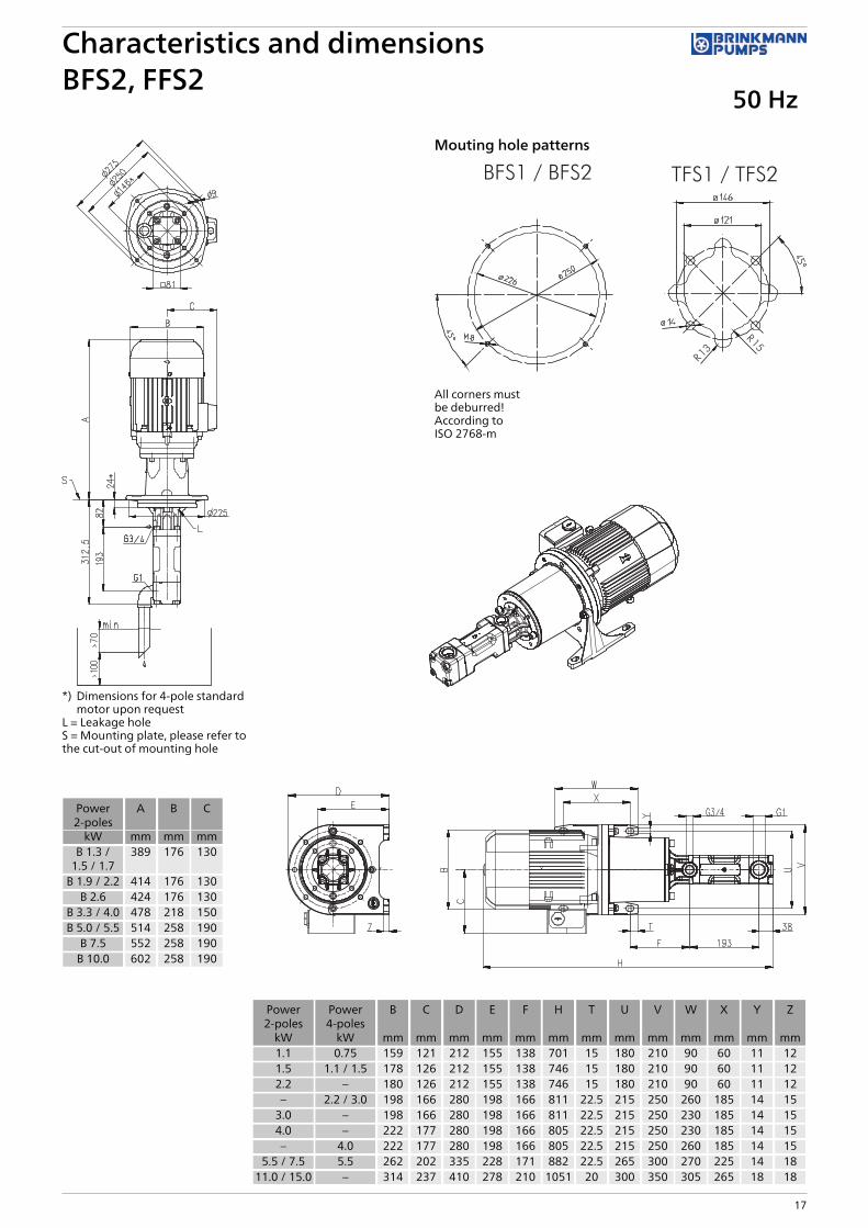
Characteristics and dimensionsBFS1, FFS1 / BFS2, FFS2
50 Hz
15
Dimensions H** = H+25 or see page 17
Power2-poles
Power4-poles
B C D E F H T U V W X Y Z
kW kW mm mm mm mm mm mm mm mm mm mm mm mm mm0.75 / 1.1 0.75 159 121 212 155 138 676 15 180 210 90 60 11 12
1.5 1.1 / 1.5 178 126 212 155 138 721 15 180 210 90 60 11 122.2 – 180 126 212 155 138 721 15 180 210 90 60 11 12– 2.2 / 3.0 198 166 280 198 166 786 22.5 215 250 260 185 14 15
3.0 – 198 166 280 198 166 786 22.5 215 250 230 185 14 154.0 – 222 177 280 198 166 780 22.5 215 250 230 185 14 15
5.5 / 7.5 – 262 202 335 228 171 857 22.5 265 300 270 225 14 18

2-pole motorrotation speed 2900 RPM
4-pole motorrotation speed 1450 RPM
Pressuremax.
Flow at viscosity Power consump-tion at viscosity
Motor Motor Weight Flow at viscosity Power consump-tion at viscosity
Motor Weight
1mm²/s
20mm²/s
1mm²/s
20mm²/s
immersionversion
footmountedversion
1mm²/s
20mm²/s
1mm²/s
20mm²/s
Type / bar l/min l/min kW kW kW kW kg l/min l/min kW kW kW kg
BFS238/ QTh1) 31 – – – – – QTh
1) 15.5 – – – –
10 28.8 30.1 0.7 0.7 B 1.3 1.1 40 13.3 14.6 0.4 0.4 0.75 2920 28.1 29.8 1.3 1.3 B 1.5 1.5 40 12.6 14.3 0.6 0.6 1.1 3230 27.4 29.5 1.8 1.8 B 1.9 2.2 44 11.9 14 0.9 0.9 1.1 3240 26.7 29.2 2.3 2.4 B 2.6 3.0 44 11.2 13.7 1.2 1.2 1.5 3450 26 28.9 2.8 2.9 B 3.3 4.0 55 10.5 13.4 1.4 1.5 2.2 4160 25.3 28.7 3.3 3.5 B 4.0 4.0 57 9.8 13.2 1.7 1.8 2.2 4170 24.6 28.4 3.8 4.0 B 4.0 5.5 57 9.1 12.9 1.9 2.0 2.2 4180 23.9 28.1 4.4 4.5 B 5.0 5.5 74 8.4 12.6 2.2 2.3 3.0 4690 23.2 27.8 4.9 5.1 B 5.5 5.5 74 7.7 12.3 2.5 2.6 3.0 46
100 22.5 27.6 5.4 5.6 B 7.5 7.5 82 7 12.1 2.7 2.9 4.0 53110 21.9 27.3 5.9 6.2 B 7.5 7.5 82 – – – – – –120 21.2 27 6.4 6.8 B 7.5 7.5 82 – – – – – –130 20.6 26.7 6.9 7.3 B 7.5 11.0 82 – – – – – –140 19.9 26.5 7.5 7.9 B 10.0 11.0 97 – – – – – –150 19.3 26.2 8.0 8.4 B 10.0 11.0 97 – – – – – –
BFS250/ QTh1) 40.8 – – – – – QTh
1) 20.4 – – – –
10 37.9 39.6 0.9 0.9 B 1.3 1.1 40 17.5 19.2 0.5 0.5 0.75 2920 37 39.2 1.6 1.6 B 1.7 2.2 40 16.6 18.8 0.8 0.8 1.1 3230 36 38.9 2.3 2.3 B 2.6 3.0 44 15.6 18.5 1.2 1.2 1.5 3440 35.1 38.5 3.0 3.1 B 3.3 4.0 44 14.7 18.1 1.5 1.6 2.2 4150 34.3 38.1 3.6 3.8 B 4.0 4.0 57 13.9 17.7 1.8 1.9 2.2 4160 33.5 37.7 4.3 4.5 B 5.0 5.5 74 13.1 17.3 2.2 2.3 3.0 4670 32.7 37.4 5.0 5.2 B 5.5 5.5 74 12.3 17 2.5 2.6 3.0 4680 31.9 37 5.7 5.9 B 7.5 7.5 82 11.5 16.6 2.9 3.0 4.0 5390 31.2 36.6 6.4 6.6 B 7.5 7.5 82 10.7 16.2 3.2 3.3 4.0 53
100 30.5 36.2 7.0 7.4 B 7.5 11.0 82 9.9 15.8 3.5 3.7 4.0 53110 29.2 35.9 7.7 8.1 B 10.0 11.0 97 – – – – – –120 27.9 35.5 8.4 8.8 B 10.0 11.0 97 – – – – – –130 26.6 35.1 9.1 9.5 B 10.0 11.0 97 – – – – – –140 25.4 34.7 9.8 10.2 – 11.0 97 – – – – – –150 24.1 34.3 10.4 11.0 – 15.0 101 – – – – – –
BFS260/ QTh1) 48.9 – – – – – QTh
1) 24.5 – – – –
10 45.5 47.4 1.0 1.1 B 1.5 1.5 40 21 23 0.5 0.6 0.75 2920 44.3 46.9 1.9 2.0 B 2.2 3.0 44 19.9 22.4 0.9 1.0 1.5 3430 43.2 46.3 2.7 2.9 B 3.3 4.0 44 18.7 21.8 1.4 1.4 2.2 4140 42 45.7 3.5 3.8 B 4.0 5.5 57 17.6 21.2 1.8 1.9 2.2 4150 40.9 45.1 4.3 4.6 B 5.0 5.5 74 16.4 20.7 2.2 2.3 3.0 4660 39.7 44.5 5.1 5.5 B 7.5 7.5 82 15.3 20 2.6 2.8 3.0 4670 38.5 43.9 5.9 6.4 B 7.5 7.5 82 14.1 19.4 3.0 3.2 4.0 5380 37.4 43.3 6.8 7.3 B 7.5 11.0 82 12.9 18.8 3.4 3.7 4.0 5390 36.2 42.6 7.6 8.1 B 10.0 11.0 97 11.8 18.2 3.8 4.1 5.5 63
100 35 42 8.5 9.0 B 10.0 11.0 97 10.6 17.6 4.3 4.5 5.5 63110 33.4 41.4 9.3 9.9 B 10.0 11.0 97 – – – – – –120 31.8 40.7 10.0 10.8 – 11.0 97 – – – – – –130 30.1 39.5 10.9 11.7 – 15.0 101 – – – – – –140 28.5 38.2 11.7 12.5 – 15.0 101 – – – – – –150 26.9 37 12.5 13.4 – 15.0 101 – – – – – –
1) QTh: Theoretical flow rateHigher pressures (up to 200 bar) upon request.Viscosity > 20 mm2/s more power consumption.
High Pressure PumpsBFS2, FFS2Screw spindles
50 Hz
16
*) Dimensions for 4-pole standardmotor upon request
L = Leakage holeS = Mounting plate, please refer tothe cut-out of mounting hole
Power2-poles
A B C
kW mm mm mmB 1.3 /
1.5 / 1.7389 176 130
B 1.9 / 2.2 414 176 130B 2.6 424 176 130
B 3.3 / 4.0 478 218 150B 5.0 / 5.5 514 258 190
B 7.5 552 258 190B 10.0 602 258 190
Mouting hole patterns
All corners mustbe deburred!According toISO 2768-m
Characteristics and dimensionsBFS2, FFS2
50 Hz
17
Power2-poles
Power4-poles
B C D E F H T U V W X Y Z
kW kW mm mm mm mm mm mm mm mm mm mm mm mm mm1.1 0.75 159 121 212 155 138 701 15 180 210 90 60 11 121.5 1.1 / 1.5 178 126 212 155 138 746 15 180 210 90 60 11 122.2 – 180 126 212 155 138 746 15 180 210 90 60 11 12– 2.2 / 3.0 198 166 280 198 166 811 22.5 215 250 260 185 14 15
3.0 – 198 166 280 198 166 811 22.5 215 250 230 185 14 154.0 – 222 177 280 198 166 805 22.5 215 250 230 185 14 15– 4.0 222 177 280 198 166 805 22.5 215 250 260 185 14 15
5.5 / 7.5 5.5 262 202 335 228 171 882 22.5 265 300 270 225 14 1811.0 / 15.0 – 314 237 410 278 210 1051 20 300 350 305 265 18 18

2-pole motorrotation speed 2900 RPM
4-pole motorrotation speed 1450 RPM
Pressuremax.
Flow at viscosity Power consump-tion at viscosity
Motor Weight Flow at viscosity Power consump-tion at viscosity
Motor Weight
1mm²/s
20mm²/s
1mm²/s
20mm²/s
1mm²/s
20mm²/s
1mm²/s
20mm²/s
Type / bar l/min l/min kW kW kW kg l/min l/min kW kW kW kg
TFS348/ QTh1) 64.1 – – – – QTh
1) 32.1 – – – –
10 60 62.3 1.5 1.6 2.2 47 28 30.3 0.7 0.8 1.1 4420 58.5 61.5 2.5 2.8 3.0 52 26.5 29.4 1.2 1.3 1.5 4630 57.1 60.7 3.6 3.9 5.5 73 25 28.6 1.8 1.9 2.2 5340 55.7 59.9 4.7 5.1 5.5 73 23.6 27.9 2.3 2.4 3.0 5850 54.4 59.2 5.7 6.2 7.5 86 22.3 27.1 2.8 3.0 4.0 6560 53.1 58.5 6.8 7.3 11.0 104 21.1 26.5 3.4 3.5 4.0 6570 51.9 57.9 7.9 8.5 11.0 104 19.8 25.8 3.9 4.1 5.5 7580 50.7 57.3 8.9 9.6 11.0 104 18.7 25.2 4.4 4.7 5.5 7590 49.6 56.7 10.0 10.7 15.0 113 17.4 24.6 5.0 5.2 5.5 75
100 48.6 56.1 11.1 11.8 15.0 113 16.2 24.1 5.5 5.8 7.5 90110 46.7 55.6 12.1 13.0 15.0 113 – – – – – –120 45 55.2 13.2 14.2 15.0 113 – – – – – –130 43.3 54.7 14.3 15.3 18.5 133 – – – – – –140 41.6 54.4 15.3 16.4 18.5 133 – – – – – –150 40 54 16.4 17.6 18.5 133 – – – – – –
TFS364/ QTh1) 85.5 – – – – QTh
1) 42.8 – – – –
10 79.9 83 1.8 2.0 3.0 52 37.1 40.3 0.9 0.9 1.5 4620 78.1 82 3.3 3.5 4.0 63 35.3 39.2 1.6 1.7 2.2 5330 76.3 81 4.7 5.0 5.5 73 33.6 38.3 2.3 2.4 3.0 5840 74.6 80.1 6.1 6.5 7.5 86 31.9 37.4 3.0 3.2 4.0 6550 73 79.2 7.5 8.0 11.0 104 30.2 36.5 3.7 3.9 5.5 7560 71.4 78.4 9.0 9.5 11.0 104 28.7 35.7 4.4 4.7 5.5 7570 69.9 77.6 10.4 10.9 15.0 113 27.1 34.9 5.1 5.4 7.5 9080 68.4 76.9 11.8 12.4 15.0 113 25.6 34.1 5.9 6.1 7.5 9090 66.9 76.1 13.2 13.9 15.0 113 24 33.4 6.6 6.9 7.5 90
100 65.5 75.5 14.7 15.4 18.5 133 22.4 32.7 7.3 7.6 11.0 112110 63.2 74.8 16.1 16.9 18.5 133 – – – – – –120 61 74.3 17.5 18.4 22.0 162 – – – – – –130 58.8 72.7 18.9 19.9 22.0 162 – – – – – –140 56.6 71.3 20.4 21.4 22.0 162 – – – – – –150 54.5 69.8 21.8 22.8 30.0 219 – – – – – –
TFS376/ QTh1) 101.5 – – – – QTh
1) 50.8 – – – –
10 95.2 98.5 2.1 2.4 4.0 63 44.5 47.8 1.0 1.2 1.5 4620 93.1 97.3 3.8 4.2 5.5 73 42.3 46.6 1.8 2.1 3.0 5830 91 96.2 5.5 6.0 7.5 86 40.3 45.4 2.7 3.0 4.0 6540 89 95.1 7.2 7.9 11.0 104 38.2 44.4 3.5 3.9 5.5 7550 87 94.1 8.9 9.7 11.0 104 36.2 43.3 4.4 4.8 5.5 7560 85 93.1 10.6 11.5 15.0 113 34.3 42.4 5.2 5.7 7.5 9070 83.1 92.2 12.2 13.3 15.0 113 32.3 41.4 6.1 6.6 7.5 9080 81.2 91.3 13.9 15.1 18.5 133 30.4 40.5 6.9 7.4 11.0 11290 79.3 90.4 15.6 16.9 18.5 133 28.4 39.7 7.8 8.4 11.0 112
100 77.5 89.6 17.3 18.8 22.0 162 26.5 38.9 8.6 9.2 11.0 112110 74.5 88.9 19.0 20.6 22.0 162 – – – – – –120 71.6 88.2 20.7 22.4 30.0 219 – – – – – –130 68.8 86.4 22.4 24.2 30.0 219 – – – – – –140 66 84.7 24.0 26.0 30.0 219 – – – – – –150 63.2 83 25.7 27.9 30.0 219 – – – – – –
1) QTh: Theoretical flow rateHigher pressures (up to 200 bar) upon request.Viscosity > 20 mm2/s more power consumption.
High Pressure PumpsTFS3, FFS3Screw spindles
50 Hz
18

L = Leakage holeS = Mounting plate, please refer tothe cut-out of mounting hole
Mouting hole patterns
All corners mustbe deburred!According toISO 2768-m
Characteristics and dimensionsTFS3, FFS3
50 Hz
19
Power2-poles
Power4-poles
A B C D E F H T U V W X Y Z
kW kW mm mm mm mm mm mm mm mm mm mm mm mm mm mm– 1.1 476 178 126 212 165 152 832 15 180 210 90 60 11 12– 1.5 533 178 126 212 165 152 832 15 180 210 90 60 11 12
2.2 – 476 180 126 212 165 152 832 15 180 210 90 60 11 12– 2.2 526 198 166 280 208 186 889 22.5 215 250 260 185 14 15
3.0 – 533 198 166 280 208 186 889 22.5 215 250 230 185 14 15– 3.0 595 198 166 280 208 186 889 22.5 215 250 260 185 14 15– 4.0 595 222 177 280 208 186 882 22.5 215 250 260 185 14 15
4.0 – 526 222 177 280 208 186 882 22.5 215 250 230 185 14 155.5 / 7.5 – 595 262 202 335 238 183 951 22.5 265 300 270 225 14 18
– 5.5 / 7.5 764 262 202 335 238 183 951 22.5 265 300 270 225 14 1811.0 /
15.0 / 18.5 11.0 764 314 237 410 288 222 1120 20 300 350 305 265 18 1822.0 – 828 356 286 410 288 222 1184 20 300 350 305 265 18 1830.0 – 881 396 315 460 313 212 1237 25 350 400 350 300 18 20

2-pole motorrotation speed 2900 RPM
4-pole motorrotation speed 1450 RPM
Pressuremax.
Flow at viscosity Power consump-tion at viscosity
Motor Weight Flow at viscosity Power consump-tion at viscosity
Motor Weight
1mm²/s
20mm²/s
1mm²/s
20mm²/s
1mm²/s
20mm²/s
1mm²/s
20mm²/s
Type / bar l/min l/min kW kW kW kg l/min l/min kW kW kW kg
TFS460/ QTh1) 125.3 – – – – QTh
1) 62.7 – – – –
10 118 122 2.7 3.0 4.0 74 55 59 1.2 1.3 1.5 5720 115 120 4.8 5.2 5.5 83 52 57 2.3 2.4 3.0 6430 112 118 6.9 7.4 11.0 115 50 56 3.3 3.5 4.0 7640 110 117 9.0 9.6 11.0 115 47 54 4.4 4.7 5.5 8550 107 116 11.0 11.8 15.0 124 44 53 5.4 5.8 7.5 10060 105 114 13.1 14.0 15.0 124 42 52 6.5 6.9 7.5 10070 102 113 15.2 16.1 18.5 144 40 50 7.5 8.0 11.0 12380 100 112 17.3 18.3 22.0 173 37 49 8.6 9.1 11.0 12390 98 111 19.4 20.5 22.0 173 35 48 9.6 10.3 11.0 123
100 96 110 21.5 22.7 30.0 230 32 47 10.7 11.3 15.0 149110 94 109 23.6 24.9 30.0 230 – – – – – –120 91 108 25.6 27.1 30.0 230 – – – – – –
TFS480/ QTh1) 167.1 – – – – QTh
1) 83.6 – – – –
10 157 162 3.4 3.7 5.5 83 74 79 1.6 1.8 2.2 6420 153 160 6.2 6.6 7.5 96 70 76 3.0 3.2 4.0 7630 150 158 9.0 9.5 11.0 115 66 74 4.4 4.7 5.5 8540 146 156 11.7 12.4 15.0 124 63 72 5.8 6.1 7.5 10050 143 154 14.5 15.2 18.5 144 60 70 7.2 7.6 11.0 12360 140 152 17.3 18.1 18.5 144 56 68 8.6 9.2 11.0 12370 137 150 20.1 21.0 22.0 173 53 67 9.9 10.6 11.0 12380 134 149 22.9 23.9 30.0 230 51 65 11.3 12.1 15.0 14990 132 147 25.7 26.7 30.0 230 47 64 12.7 13.6 15.0 149
100 129 146 28.5 29.6 30.0 230 44 63 14.1 15.0 18.5 168110 126 145 31.3 32.5 37.0 259 – – – – – –120 124 144 34.0 35.4 37.0 259 – – – – – –
TFS496/ QTh1) 200.5 – – – – QTh
1) 100.3 – – – –
10 189 194 3.9 4.4 5.5 83 89 94 1.9 2.1 3.0 6420 185 192 7.3 8.0 11.0 115 85 92 3.5 3.9 5.5 8530 181 190 10.6 11.5 15.0 124 80 90 5.2 5.7 7.5 10040 177 188 14.0 15.1 18.5 144 76 88 6.9 7.5 11.0 12350 173 186 17.3 18.6 22.0 173 72 86 8.6 9.3 11.0 12360 169 184 20.7 22.2 30.0 230 69 84 10.2 11.1 15.0 14970 166 182 24.0 25.7 30.0 230 65 82 11.9 12.9 15.0 14980 162 180 27.3 29.3 37.0 259 62 80 13.6 14.8 18.5 16890 159 179 30.7 32.8 37.0 259 58 78 15.3 16.6 18.5 168
100 156 177 34.0 36.4 45.0 374 55 77 16.9 18.4 22.0 188110 153 176 37.4 39.9 45.0 374 – – – – – –120 149 174 40.7 43.5 45.0 374 – – – – – –
1) QTh: Theoretical flow rateViscosity > 20 mm2/s more power consumption.
High Pressure PumpsTFS4, FFS4Screw spindles
50 Hz
20
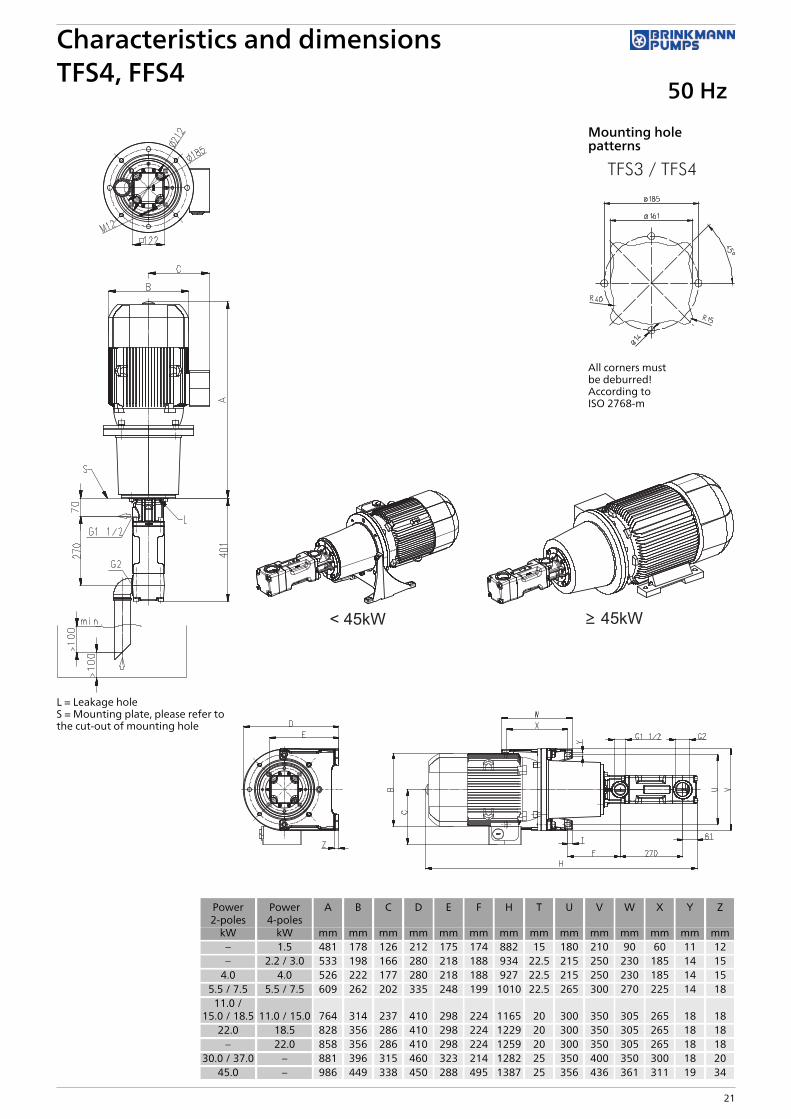
L = Leakage holeS = Mounting plate, please refer tothe cut-out of mounting hole
Mounting holepatterns
All corners mustbe deburred!According toISO 2768-m
Characteristics and dimensionsTFS4, FFS4
50 Hz
21
Power2-poles
Power4-poles
A B C D E F H T U V W X Y Z
kW kW mm mm mm mm mm mm mm mm mm mm mm mm mm mm– 1.5 481 178 126 212 175 174 882 15 180 210 90 60 11 12– 2.2 / 3.0 533 198 166 280 218 188 934 22.5 215 250 230 185 14 15
4.0 4.0 526 222 177 280 218 188 927 22.5 215 250 230 185 14 155.5 / 7.5 5.5 / 7.5 609 262 202 335 248 199 1010 22.5 265 300 270 225 14 18
11.0 /15.0 / 18.5 11.0 / 15.0 764 314 237 410 298 224 1165 20 300 350 305 265 18 18
22.0 18.5 828 356 286 410 298 224 1229 20 300 350 305 265 18 18– 22.0 858 356 286 410 298 224 1259 20 300 350 305 265 18 18
30.0 / 37.0 – 881 396 315 460 323 214 1282 25 350 400 350 300 18 2045.0 – 986 449 338 450 288 495 1387 25 356 436 361 311 19 34

2-pole motorrotation speed 2900 RPM
4-pole motorrotation speed 1450 RPM
Pressuremax.
Flow at viscosity Power consump-tion at viscosity
Motor Weight Flow at viscosity Power consump-tion at viscosity
Motor Weight
1mm²/s
20mm²/s
1mm²/s
20mm²/s
1mm²/s
20mm²/s
1mm²/s
20mm²/s
Type / bar l/min l/min kW kW kW kg l/min l/min kW kW kW kg
TFS574/ QTh1) 241.6 – – – – QTh
1) 120.8 – – – –
10 230 235 5.0 5.7 7.5 125 109 114 2.3 2.7 4.0 10520 226 233 9.1 9.9 11.0 144 105 112 4.3 4.8 5.5 11430 222 231 13.1 14.2 15.0 153 101 110 6.3 7.0 7.5 12940 219 229 17.1 18.4 22.0 202 98 109 8.4 9.1 11.0 15250 216 228 21.1 22.6 30.0 259 95 107 10.4 11.3 15.0 17860 213 226 25.2 26.9 30.0 259 92 105 12.4 13.4 15.0 17870 210 224 29.2 31.1 37.0 288 89 104 14.4 15.5 18.5 19780 207 223 33.2 35.4 37.0 288 86 102 16.4 17.7 18.5 19790 204 221 37.2 39.6 45.0 403 83 101 18.4 19.8 22.0 217
100 202 220 41.3 43.8 45.0 403 80 99 20.5 21.9 30.0 273110 199 219 45.3 48.1 55.0 498 – – – – – –120 196 217 49.3 52.3 55.0 498 – – – – – –
TFS5100/ QTh1) 326.5 – – – – QTh
1) 163.3 – – – –
10 310 318 6.4 7.1 11.0 144 147 155 3.0 3.5 5.5 11420 306 316 11.9 12.9 15.0 153 143 152 5.7 6.4 7.5 12930 302 313 17.3 18.6 22.0 202 139 150 8.5 9.3 11.0 15240 298 311 22.8 24.4 30.0 259 135 148 11.2 12.2 15.0 17850 294 309 28.2 30.2 37.0 288 131 146 13.9 15.1 18.5 19760 291 307 33.7 36.0 37.0 288 127 144 16.6 18.0 18.5 19770 287 305 39.1 41.7 45.0 403 124 142 19.3 20.9 22.0 21780 284 303 44.5 47.5 55.0 498 120 140 22.1 23.9 30.0 27390 280 302 50.0 53.3 55.0 498 116 138 24.8 26.8 30.0 273
100 277 300 55.4 59.1 75.0 608 113 137 27.5 29.7 37.0 363110 273 299 60.9 64.8 75.0 608 – – – – – –120 270 297 66.3 70.6 75.0 608 – – – – – –
1) QTh: Theoretical flow rateViscosity > 20 mm2/s more power consumption.
High Pressure PumpsTFS5, FFS5Screw spindles
50 Hz
22

L = Leakage holeS = Mounting plate, please refer tothe cut-out of mounting hole
Mounting hole patterns
All corners mustbe deburredAccording toISO 2768-m
Characteristics and dimensionsTFS5, FFS5
50 Hz
23
Power2-poles
Power4-poles
A B C D F H T U V W X Y Z
kW kW mm mm mm mm mm mm mm mm mm mm mm mm mm– 4.0 556 222 177 280 228 1051 22.5 215 250 230 185 14 15
7.5 5.5 / 7.5 622 262 202 335 222 1117 22.5 265 300 270 225 14 1811.0 / 15.0 11.0 / 15.0 767 314 237 410 237 1262 20 300 350 305 265 18 18
22.0 18.5 831 356 286 410 237 1326 20 300 350 305 265 18 18– 22.0 861 356 286 410 237 1356 20 300 350 305 265 18 18
30.0 / 37.0 30.0 884 396 315 460 227 1379 25 350 400 350 300 18 20– 37.0 927 449 338 520 223 1422 25 400 450 385 335 18 20
45.0 – 989 449 338 450 508 1484 25 356 436 361 311 19 3455.0 – 1059 497 410 525 560 1554 30 406 490 409 349 24 4075.0 – 1135 551 433 555 582 1630 55.5 457 540 479 368 24 40

2-pole motorrotation speed 2900 RPM
4-pole motorrotation speed 1450 RPM
Pressuremax.
Flow at viscosity Power consump-tion at viscosity
Motor Weight Flow at viscosity Power consump-tion at viscosity
Motor Weight
1mm²/s
20mm²/s
1mm²/s
20mm²/s
1mm²/s
20mm²/s
1mm²/s
20mm²/s
Type / bar l/min l/min kW kW kW kg l/min l/min kW kW kW kg
TFS5120/ QTh1) 391.8 – – – – QTh
1) 195.9 – – – –
10 372 382 7.5 8.7 11.0 144 176 186 3.6 4.1 5.5 11420 366 379 14.1 15.6 18.5 173 171 183 6.8 7.6 11.0 15230 361 376 20.6 22.5 30.0 259 165 180 10.1 11.1 15.0 17840 355 373 27.1 29.5 37.0 288 160 177 13.4 14.6 18.5 19750 350 370 33.7 36.4 45.0 403 154 175 16.6 18.1 22.0 21760 345 368 40.2 43.3 45.0 403 149 172 19.9 21.6 22.0 21770 340 366 46.7 50.2 55.0 498 144 170 23.2 25.1 30.0 27380 336 364 53.2 57.1 75.0 608 140 168 26.4 28.6 30.0 27390 331 362 59.8 64.0 75.0 608 134 166 29.7 32.1 37.0 363
100 327 360 66.3 71.0 75.0 608 129 164 33.0 35.6 37.0 363110 322 358 72.8 77.9 90.0 693 – – – – – –120 318 357 79.4 84.8 90.0 693 – – – – – –
TFS5130/ QTh1) 424.5 – – – – QTh
1) 212.2 – – – –
10 403 412 8.1 9.2 11.0 144 191 199 3.8 4.3 5.5 11420 396 407 15.1 16.5 18.5 173 184 195 7.4 8.0 11.0 15230 389 402 22.2 23.7 30.0 259 177 190 10.9 11.7 15.0 17840 383 398 29.3 31.0 37.0 288 171 186 14.4 15.3 18.5 19750 377 394 36.4 38.3 45.0 403 165 181 18.0 19.0 22.0 21760 371 390 43.4 45.6 55.0 498 159 177 21.5 22.7 30.0 27370 366 386 50.5 52.8 55.0 498 154 174 25.1 26.4 30.0 27380 361 382 57.6 60.1 75.0 608 149 170 28.6 30.0 37.0 36390 357 379 64.7 67.4 75.0 608 143 166 32.1 33.7 37.0 363
100 352 375 71.7 74.7 90.0 693 138 163 35.7 37.4 45.0 403110 347 372 78.8 81.9 90.0 693 – – – – – –120 343 369 85.9 89.2 110.0 868 – – – – – –
1) QTh: Theoretical flow rateViscosity > 20 mm2/s more power consumption.
High Pressure PumpsTFS5, FFS5Screw spindles
50 Hz
24

L = Leakage holeS = Mounting plate, please refer tothe cut-out of mounting hole
Mounting hole patterns
All corners mustbe deburredAccording toISO 2768-m
Characteristics and dimensionsTFS5, FFS5
50 Hz
25
Power2-poles
Power4-poles
A B C D F H T U V W X Y Z
kW kW mm mm mm mm mm mm mm mm mm mm mm mm mm– 5.5 622 262 202 335 222 1117 22.5 265 300 270 225 14 18
11.0 / 18.5 11.0 / 15.0 767 314 237 410 237 1262 20 300 350 305 265 18 18– 18.5 831 356 286 410 237 1326 20 300 350 305 265 18 18– 22.0 861 356 286 410 237 1356 20 300 350 305 265 18 18
30.0 / 37.0 30.0 884 396 315 460 227 1379 25 350 400 350 300 18 20– 37.0 927 449 338 520 223 1422 25 400 450 385 335 18 20
45.0 – 989 449 338 450 508 1484 25 356 436 361 311 19 34– 45.0 987 449 338 450 508 1482 25 356 436 361 311 19 34
55.0 – 1059 497 410 525 560 1554 30 406 490 409 349 24 4075.0 – 1135 551 433 555 582 1630 55.5 457 540 479 368 24 4090.0 – 1135 551 433 555 582 1630 30 457 540 479 419 24 40
110.0 – 1239 616 515 645 623 1734 35 508 628 527 457 35 52

2-pole motorrotation speed 2900 RPM
4-pole motorrotation speed 1450 RPM
Pressuremax.
Flow at viscosity Power consump-tion at viscosity
Motor Weight Flow at viscosity Power consump-tion at viscosity
Motor Weight
1mm²/s
20mm²/s
1mm²/s
20mm²/s
1mm²/s
20mm²/s
1mm²/s
20mm²/s
Type / bar l/min l/min kW kW kW kg l/min l/min kW kW kW kg
TFS690/ QTh1) 459 – – – – QTh
1) 230 – – – –
10 445 450 9.5 11.2 15.0 213 216 220 4.4 5.1 7.5 19020 437 445 17.1 18.8 22.0 262 207 216 8.3 9.0 11.0 21230 429 440 24.8 26.5 30.0 319 199 211 12.1 12.8 15.0 23840 421 436 32.4 34.1 37.0 348 191 206 15.9 16.6 18.5 25750 414 432 40.1 41.8 45.0 464 184 202 19.7 20.4 22.0 27760 407 428 47.7 49.4 55.0 559 177 198 23.6 24.3 30.0 33370 401 424 55.4 57.1 75.0 669 171 194 27.4 28.1 30.0 33380 395 420 63.0 64.7 75.0 669 165 190 31.2 31.9 37.0 424
TFS6120/ QTh1) 612 – – – – QTh
1) 306 – – – –
10 594 600 12.0 13.7 18.5 233 288 294 5.7 6.4 7.5 19020 584 594 22.2 23.9 30.0 319 278 288 10.8 11.5 15.0 23830 574 588 32.4 34.1 37.0 348 268 282 15.9 16.6 18.5 25740 565 583 42.6 44.3 55.0 559 259 277 21.0 21.7 30.0 33350 557 578 52.8 54.5 75.0 669 251 272 26.1 26.8 30.0 33360 549 573 63.0 64.7 75.0 669 243 267 31.2 31.9 37.0 42470 542 568 73.2 74.9 90.0 754 236 262 36.3 37.0 45.0 46480 533 563 83.4 85.1 90.0 754 227 257 41.4 42.1 45.0 464
TFS6145/ QTh1) 740 – – – – QTh
1) 370 – – – –
10 717 725 14.1 15.8 18.5 233 348 355 6.8 7.5 11.0 21220 704 715 26.5 28.2 30.0 319 334 345 12.9 13.6 15.0 23830 692 706 38.8 40.5 45.0 464 322 337 19.1 19.8 22.0 27740 680 698 51.1 52.8 55.0 559 310 328 25.3 26.0 30.0 33350 669 691 63.4 65.1 75.0 669 299 321 31.4 32.1 37.0 42460 658 684 75.8 77.5 90.0 754 288 314 37.6 38.3 45.0 46470 646 676 88.1 89.8 110.0 929 276 306 43.8 44.5 55.0 52980 635 668 100.4 102.1 110.0 929 265 298 49.9 50.6 55.0 529
1) QTh: Theoretical flow rateViscosity > 20 mm2/s more power consumption.All 6 series screw pumps with an operating flow rate of 800 l/min or above must be operated with a feed pump which supplies fluidwith at least 1bar of pressure to the pump inlet.
High Pressure PumpsTFS6, FFS6Screw spindles
50 Hz
26

L = Leakage holeS = Mounting plate, please refer tothe cut-out of mounting hole
Mounting hole patterns
All corners mustbe deburred!According toISO 2768-m
Characteristics and dimensionsTFS6, FFS6
50 Hz
27
Power2-poles
Power4-poles
A B C D F H T U V W X Y Z
kW kW mm mm mm mm mm mm mm mm mm mm mm mm mm– 7.5 673 262 202 335 252 1292 22.5 265 300 270 225 14 18
15.0 / 18.5 11.0 795 314 237 410 252 1414 20 300 350 305 265 18 18– 15.0 795 314 237 410 265 1414 20 300 350 305 265 18 18– 18.5 859 356 286 410 265 1478 20 300 350 305 265 18 18
22.0 – 859 356 286 410 252 1478 20 300 350 305 265 18 18– 22.0 889 356 286 410 397 1508 20 300 350 305 265 18 18
30.0 / 37.0 – 910 396 315 460 265 1529 25 350 400 350 300 18 20– 30.0 910 396 315 460 417 1529 25 350 400 350 300 18 20– 37.0 973 449 338 520 432 1592 25 400 450 385 335 18 20
45.0 – 1015 449 338 450 546 1634 25 356 436 361 311 19 34– 45.0 1013 449 338 450 546 1632 25 356 436 361 311 19 34
55.0 – 1072 497 410 525 585 1691 30 406 490 409 349 24 4075.0 – 1163 551 433 555 622 1782 55.5 457 540 479 368 24 4090.0 – 1163 551 433 555 622 1782 30 457 540 479 419 24 40

2-pole motorrotation speed 3500 RPM
4-pole motorrotation speed 1750 RPM
Pressuremax.
Flow at viscosity Power consump-tion at viscosity
Motor Motor Weight Flow at viscosity Power consump-tion at viscosity
Motor Weight
1mm²/s
20mm²/s
1mm²/s
20mm²/s
immersionversion
footmountedversion
1mm²/s
20mm²/s
1mm²/s
20mm²/s
Type / bar l/min l/min kW kW kW kW kg l/min l/min kW kW kW kg
BFS130/ QTh1) 18.8 – – – – – QTh
1) 9.4 – – – –
10 17.3 18.2 0.6 0.6 B 1.5 0.86 39 7.9 8.8 0.3 0.3 0.86 2920 16.3 17.8 0.9 0.9 B 1.5 1.3 39 6.9 8.4 0.4 0.4 0.86 2930 15.4 17.5 1.2 1.2 B 1.5 1.75 39 5.9 8 0.6 0.6 0.86 2940 14.5 17.1 1.5 1.5 B 1.75 1.75 39 5 7.7 0.7 0.8 1.27 3150 13.6 16.7 1.8 1.9 B 1.95 2.55 39 4 7.3 0.9 1.0 1.27 3160 12.7 16.4 2.1 2.2 B 2.2 2.55 43 3.2 7 1.0 1.1 1.27 3170 11.9 16 2.4 2.5 B 2.55 3.45 43 - 6.6 - 1.3 1.75 3480 11.1 15.7 2.8 2.9 B 3.0 3.45 44 - 6.3 - 1.5 1.75 3490 10.4 15.4 3.1 3.2 B 3.8 3.45 54 - 6 - 1.6 1.75 34
100 9.6 15.1 3.4 3.5 B 3.8 4.6 54 - 5.6 - 1.8 2.55 41110 8.7 14.7 3.7 3.9 B 4.6 4.6 57 - 5.3 - 2.0 2.55 41120 7.8 14.4 4.0 4.2 B 4.6 4.6 57 - 5 - 2.1 2.55 41130 - 14.1 - 4.5 B 4.6 6.3 57 – – – – – –140 - 13.8 - 4.9 B 5.75 6.3 73 – – – – – –150 - 13.5 - 5.2 B 5.75 6.3 73 – – – – – –
BFS140/ QTh1) 25.2 – – – – – QTh
1) 12.6 – – – –
10 23.1 24.4 0.7 0.7 B 1.5 0.86 39 10.5 11.8 0.3 0.4 0.86 2920 21.8 23.9 1.1 1.2 B 1.5 1.75 39 9.2 11.3 0.5 0.6 0.86 2930 20.6 23.4 1.5 1.6 B 1.75 1.75 39 8 10.7 0.7 0.8 1.27 3140 19.5 22.9 1.9 2.0 B 2.2 2.55 43 6.9 10.2 0.9 1.0 1.27 3150 18.4 22.4 2.4 2.5 B 2.55 3.45 43 5.8 9.8 1.1 1.2 1.75 3460 17.3 21.9 2.8 2.9 B 3.0 3.45 44 4.7 9.3 1.3 1.5 1.75 3470 16.4 21.4 3.2 3.3 B 3.8 3.45 54 3.8 8.8 1.5 1.7 2.55 4180 15.4 20.9 3.6 3.8 B 3.8 4.6 54 - 8.3 - 1.9 2.55 4190 14.6 20.5 4.0 4.2 B 4.6 4.6 57 - 7.9 - 2.1 2.55 41
100 13.8 20 4.5 4.7 B 5.75 6.3 73 - 7.4 - 2.3 2.55 41110 12.6 19.6 4.9 5.1 B 5.75 6.3 73 - 7 - 2.5 3.45 46120 11.6 19.2 5.3 5.5 B 5.75 6.3 73 - 6.5 - 2.7 3.45 46130 10.6 18.7 5.7 6.0 B 6.3 6.3 73 – – – – – –140 9.7 18.3 6.1 6.4 B 8.6 8.6 81 – – – – – –150 8.8 17.9 6.6 6.9 B 8.6 8.6 81 – – – – – –
BFS232/ QTh1) 31.5 – – – – – QTh
1) 15.8 – – – –
10 29.7 30.8 0.8 0.9 B 1.5 1.3 40 13.9 15.1 0.4 0.5 0.86 2920 29 30.6 1.4 1.4 B 1.75 1.75 40 13.3 14.8 0.7 0.7 0.86 2930 28.4 30.3 1.9 2.0 B 2.2 2.55 44 12.7 14.6 0.9 1.0 1.27 3240 27.8 30 2.4 2.5 B 2.55 3.45 44 12.1 14.3 1.2 1.3 1.75 3450 27.2 29.8 2.9 3.1 B 3.8 3.45 55 11.5 14 1.4 1.5 1.75 3460 26.6 29.5 3.5 3.6 B 3.8 4.6 55 10.9 13.8 1.7 1.8 2.55 4170 26 29.3 4.0 4.2 B 4.6 4.6 57 10.3 13.5 2.0 2.1 2.55 4180 25.4 29 4.5 4.7 B 5.75 6.3 74 9.7 13.3 2.2 2.3 2.55 4190 24.9 28.7 5.0 5.3 B 5.75 6.3 74 9.1 13 2.5 2.6 3.45 46
100 24.3 28.5 5.6 5.8 B 6.3 6.3 74 8.5 12.7 2.7 2.9 3.45 46110 23.8 28.3 6.1 6.4 B 8.6 8.6 82 - 12.5 - 3.2 3.45 46120 23.2 28 6.6 6.9 B 8.6 8.6 82 - 12.3 - 3.4 4.55 53130 22.7 27.8 7.1 7.5 B 8.6 8.6 82 - 12 - 3.7 4.55 53140 22.1 27.5 7.7 8.0 B 8.6 8.6 82 - 11.8 - 4.0 4.55 53150 21.6 27.3 8.2 8.6 B 8.6 12.6 82 - 11.6 - 4.2 4.55 53
1) QTh: Theoretical flow rateHigher pressures (up to 200 bar) upon request.Viscosity > 20 mm2/s more power consumption.
High Pressure PumpsBFS1, FFS1 / BFS2, FFS2Screw spindles
60 Hz
28

*) Dimensions for 4-pole standardmotor upon request
**) Dimensions for BFS2L = Leakage holeS = Mounting plate, please refer tothe cut-out of mounting hole
Power2-poles
A B C
kW mm mm mmB 1.5 /
1.75 / 1.95389 176 130
B 2.2 / 2.55 414 176 130B 3.0 424 176 130
B 3.8 / 4.6 478 218 150B 5.75 / 6.3 514 258 190
B 8.6 552 258 190
Mounting hole patterns
All corners mustbe deburred!According toISO 2768-m
Characteristics and dimensionsBFS1, FFS1 / BFS2, FFS2
60 Hz
29
Dimensions H** = H+25 or see page 31
Power2-poles
Power4-poles
B C D E F H T U V W X Y Z
kW kW mm mm mm mm mm mm mm mm mm mm mm mm mm0.86 / 1.3 0.86 159 121 212 155 138 676 15 180 210 90 60 11 12
1.75 1.27 / 1.75 178 126 212 155 138 721 15 180 210 90 60 11 122.55 – 180 126 212 155 138 721 15 180 210 90 60 11 12
– 2.55 / 3.45 198 166 280 198 166 786 22.5 215 250 260 185 14 153.45 – 198 166 280 198 166 786 22.5 215 250 230 185 14 15
– 4.55 222 177 280 198 166 780 22.5 215 250 260 185 14 154.6 – 222 177 280 198 166 780 22.5 215 250 230 185 14 15
6.3 / 8.6 – 262 202 335 228 171 857 22.5 265 300 270 225 14 1812.6 – 314 237 410 278 210 1026 20 300 350 305 265 18 18

2-pole motorrotation speed 3500 RPM
4-pole motorrotation speed 1750 RPM
Pressuremax.
Flow at viscosity Power consump-tion at viscosity
Motor Motor Weight Flow at viscosity Power consump-tion at viscosity
Motor Weight
1mm²/s
20mm²/s
1mm²/s
20mm²/s
immersionversion
footmountedversion
1mm²/s
20mm²/s
1mm²/s
20mm²/s
Type / bar l/min l/min kW kW kW kW kg l/min l/min kW kW kW kg
BFS238/ QTh1) 37.4 – – – – – QTh
1) 18.7 – – – –
10 35.2 36.5 0.9 0.9 B 1.5 1.3 40 16.5 17.8 0.4 0.4 0.86 2920 34.5 36.2 1.6 1.6 B 1.75 1.75 40 15.8 17.5 0.8 0.8 1.27 3230 33.8 35.9 2.2 2.2 B 2.55 2.55 44 15.1 17.2 1.1 1.1 1.27 3240 33.1 35.6 2.8 2.9 B 3.0 3.45 44 14.4 16.9 1.4 1.4 1.75 3450 32.4 35.3 3.4 3.5 B 3.8 4.6 55 13.7 16.6 1.7 1.8 2.55 4160 31.7 35.1 4.1 4.2 B 4.6 4.6 57 13 16.4 2.0 2.1 2.55 4170 31 34.8 4.7 4.8 B 5.75 6.3 74 12.3 16.1 2.3 2.4 3.45 4680 30.3 34.5 5.3 5.5 B 5.75 6.3 74 11.6 15.8 2.6 2.7 3.45 4690 29.6 34.2 5.9 6.1 B 6.3 6.3 74 10.9 15.5 2.9 3.1 3.45 46
100 29 34 6.6 6.8 B 8.6 8.6 82 10.2 15.3 3.2 3.4 4.55 53110 28.3 33.7 7.2 7.4 B 8.6 8.6 82 - 15 - 3.7 4.55 53120 27.6 33.4 7.8 8.1 B 8.6 8.6 82 - 14.7 - 4.1 4.55 53130 27 33.1 8.4 8.8 B 11.5 12.6 97 - 14.4 - 4.4 6.3 63140 26.3 32.9 9.0 9.4 B 11.5 12.6 97 - 14.2 - 4.7 6.3 63150 25.7 32.6 9.7 10.1 B 11.5 12.6 97 - 13.9 - 5.0 6.3 63
BFS250/ QTh1) 49.2 – – – – – QTh
1) 24.6 – – – –
10 46.4 48 1.1 1.2 B 1.75 1.75 40 21.8 23.4 0.5 0.6 0.86 2920 45.4 47.7 2.0 2.0 B 2.2 2.55 44 20.8 23 1.0 1.0 1.27 3230 44.5 47.3 2.8 2.9 B 3.0 3.45 44 19.9 22.7 1.4 1.4 1.75 3440 43.6 46.9 3.6 3.8 B 3.8 4.6 55 19 22.3 1.8 1.9 2.55 4150 42.7 46.6 4.4 4.6 B 5.75 6.3 74 18.1 21.9 2.2 2.3 2.55 4160 41.9 46.2 5.2 5.5 B 5.75 6.3 74 17.3 21.6 2.6 2.7 3.45 4670 41.1 45.8 6.1 6.3 B 8.6 8.6 82 16.5 21.2 3.0 3.2 3.45 4680 40.3 45.4 6.9 7.2 B 8.6 8.6 82 15.7 20.8 3.4 3.6 4.55 5390 39.6 45.1 7.7 8.1 B 8.6 8.6 82 14.9 20.4 3.8 4.0 4.55 53
100 38.9 44.7 8.5 8.9 B 11.5 12.6 97 14 20.1 4.2 4.5 6.3 63110 37.6 44.3 9.3 9.8 B 11.5 12.6 97 - 19.7 - 4.9 6.3 63120 36.3 43.9 10.2 10.5 B 11.5 12.6 97 - 19.3 - 5.3 6.3 63130 35.1 43.5 11.0 11.5 B 11.5 12.6 97 - 18.9 - 5.8 6.3 63140 33.8 43.1 11.8 12.3 – 17.3 101 - 18.5 - 6.2 8.6 78150 32.6 42.7 12.6 13.2 – 17.3 101 - 18.1 - 6.6 8.6 78
BFS260/ QTh1) 59 – – – – – QTh
1) 29.5 – – – –
10 55.6 57.6 1.3 1.5 B 2.2 2.55 44 26.1 28 0.6 0.7 0.86 2920 54.4 57 2.3 2.5 B 3.0 3.45 44 24.9 27.5 1.1 1.3 2.55 4130 53.3 56.4 3.3 3.6 B 3.8 4.6 55 23.8 26.9 1.6 1.8 2.55 4140 52.1 55.8 4.3 4.6 B 4.6 6.3 57 22.6 26.3 2.1 2.3 2.55 4150 51 55.2 5.2 5.7 B 5.75 6.3 74 21.5 25.7 2.6 2.9 3.45 4660 49.8 54.6 6.2 6.7 B 8.6 8.6 82 20.3 25.1 3.1 3.4 4.55 5370 48.6 54 7.2 7.8 B 8.6 8.6 82 19.1 24.5 3.6 3.9 4.55 5380 47.5 53.4 8.2 8.8 B 11.5 12.6 97 18 23.9 4.1 4.4 4.55 5390 46.3 52.8 9.2 9.9 B 11.5 12.6 97 16.8 23.2 4.6 5.0 6.3 63
100 45.1 52.1 10.2 11.0 B 11.5 12.6 97 15.7 22.6 5.1 5.5 6.3 63110 43.5 51.5 11.2 12.1 – 12.6 97 - 22 - 6.0 8.6 78120 41.9 50.8 12.1 13.1 – 17.3 101 - 21.3 - 6.6 8.6 78130 40.2 49.6 13.1 14.2 – 17.3 101 – – – – – –140 38.6 48.3 14.1 15.2 – 17.3 101 – – – – – –150 37 47.1 15.1 16.3 – 17.3 101 – – – – – –
1) QTh: Theoretical flow rateHigher pressures (up to 200 bar) upon request.Viscosity > 20 mm2/s more power consumption.
High Pressure PumpsBFS2, FFS2Screw spindles
60 Hz
30

*) Dimensions for 4-pole standardmotor upon request
L = Leakage holeS = Mounting plate, please refer tothe cut-out of mounting hole
Power2-poles
A B C
kW mm mm mmB 1.5 / 1.75 389 176 130B 2.2 / 2.55 414 176 130
B 3.0 424 176 130B 3.8 / 4.6 478 218 150
B 5.75 / 6.3 514 258 190B 8.6 552 258 190
B 11.5 602 258 190
Mounting hole patterns
All corners mustbe deburred!According toISO 2768-m
Characteristics and dimensionsBFS2, FFS2
60 Hz
31
Power2-poles
Power4-poles
B C D E F H T U V W X Y Z
kW kW mm mm mm mm mm mm mm mm mm mm mm mm mm1.3 0.86 159 121 212 155 138 701 15 180 210 90 60 11 12
1.75 1.27 / 1.75 178 126 212 155 138 746 15 180 210 90 60 11 122.55 – 180 126 212 155 138 746 15 180 210 90 60 11 12
– 2.55 / 3.45 198 166 280 198 166 811 22.5 215 250 260 185 14 153.45 – 198 166 280 198 166 811 22.5 215 250 230 185 14 15
– 4.55 222 177 280 198 166 805 22.5 215 250 260 185 14 154.6 – 222 177 280 198 166 805 22.5 215 250 230 185 14 15
6.3 / 8.6 6.3 / 8.6 262 202 335 228 171 882 22.5 265 300 270 225 14 1812.6 / 17.3 – 314 237 410 278 210 1051 20 300 350 305 265 18 18

2-pole motorrotation speed 3500 RPM
4-pole motorrotation speed 1750 RPM
Pressuremax.
Flow at viscosity Power consump-tion at viscosity
Motor Weight Flow at viscosity Power consump-tion at viscosity
Motor Weight
1mm²/s
20mm²/s
1mm²/s
20mm²/s
1mm²/s
20mm²/s
1mm²/s
20mm²/s
Type / bar l/min l/min kW kW kW kg l/min l/min kW kW kW kg
TFS348/ QTh1) 77.4 – – – – QTh
1) 38.7 – – – –
10 73.3 75.6 1.8 1.9 2.55 47 34.6 36.9 0.8 0.8 1.27 4420 71.8 74.7 3.1 3.3 4.6 63 33.1 36 1.5 1.5 1.75 4630 70.3 73.9 4.4 4.6 6.3 73 31.7 35.3 2.1 2.2 2.55 5340 69 73.2 5.7 6.0 8.6 86 30.3 34.5 2.8 2.9 3.45 5850 67.6 72.5 6.9 7.3 8.6 86 28.9 33.8 3.4 3.6 4.55 6560 66.4 71.8 8.2 8.6 12.6 104 27.7 33.1 4.1 4.3 4.55 6570 65.2 71.1 9.5 10.0 12.6 104 26.5 32.4 4.7 5.0 6.3 7580 64 70.5 10.8 11.3 12.6 104 25.3 31.8 5.4 5.7 6.3 7590 62.9 69.9 12.1 12.7 17.3 113 24 31.3 6.0 6.4 8.6 90
100 61.9 69.4 13.4 14.0 17.3 113 22.8 30.7 6.7 7.1 8.6 90110 60 68.9 14.7 15.3 17.3 113 - 30.2 - 7.8 8.6 90120 58.2 68.4 15.9 16.7 17.3 113 - 29.8 - 8.5 12.6 112130 56.6 68 17.2 18.0 21.3 133 - 29.3 - 9.2 12.6 112140 54.9 67.6 18.5 19.3 21.3 133 - 28.9 - 9.9 12.6 112150 53.3 67.3 19.8 20.7 25.3 162 - 28.6 - 10.6 12.6 112
TFS364/ QTh1) 103.2 – – – – QTh
1) 51.6 – – – –
10 97.5 100.7 2.2 2.4 4.6 63 45.9 49.1 1.1 1.1 1.27 4420 95.8 99.7 3.9 4.2 6.3 73 44.2 48.1 1.9 2.0 2.55 5330 94 98.7 5.7 6.0 8.6 86 42.4 47.1 2.8 2.9 3.45 5840 92.3 97.8 7.4 7.7 12.6 104 40.7 46.2 3.6 3.8 4.55 6550 90.7 96.9 9.1 9.5 12.6 104 39.1 45.3 4.5 4.7 6.3 7560 89.1 96.1 10.8 11.3 12.6 104 37.5 44.5 5.4 5.6 6.3 7570 87.5 95.3 12.5 13.1 17.3 113 35.9 43.7 6.2 6.5 8.6 9080 86 94.5 14.3 14.9 17.3 113 34.4 42.9 7.1 7.4 8.6 9090 84.6 93.8 16.0 16.7 17.3 113 32.8 42.2 7.9 8.3 8.6 90
100 83.2 93.2 17.7 18.4 21.3 133 31.2 41.6 8.8 9.2 12.6 112110 80.9 92.5 19.4 20.2 21.3 133 - 40.9 - 10.1 12.6 112120 78.6 91.9 21.2 22.0 25.3 162 - 40.3 - 11.0 12.6 112130 76.4 90.4 22.9 23.8 33.5 219 – – – – – –140 74.3 89 24.6 25.6 33.5 219 – – – – – –150 72.2 87.5 26.3 27.3 33.5 219 – – – – – –
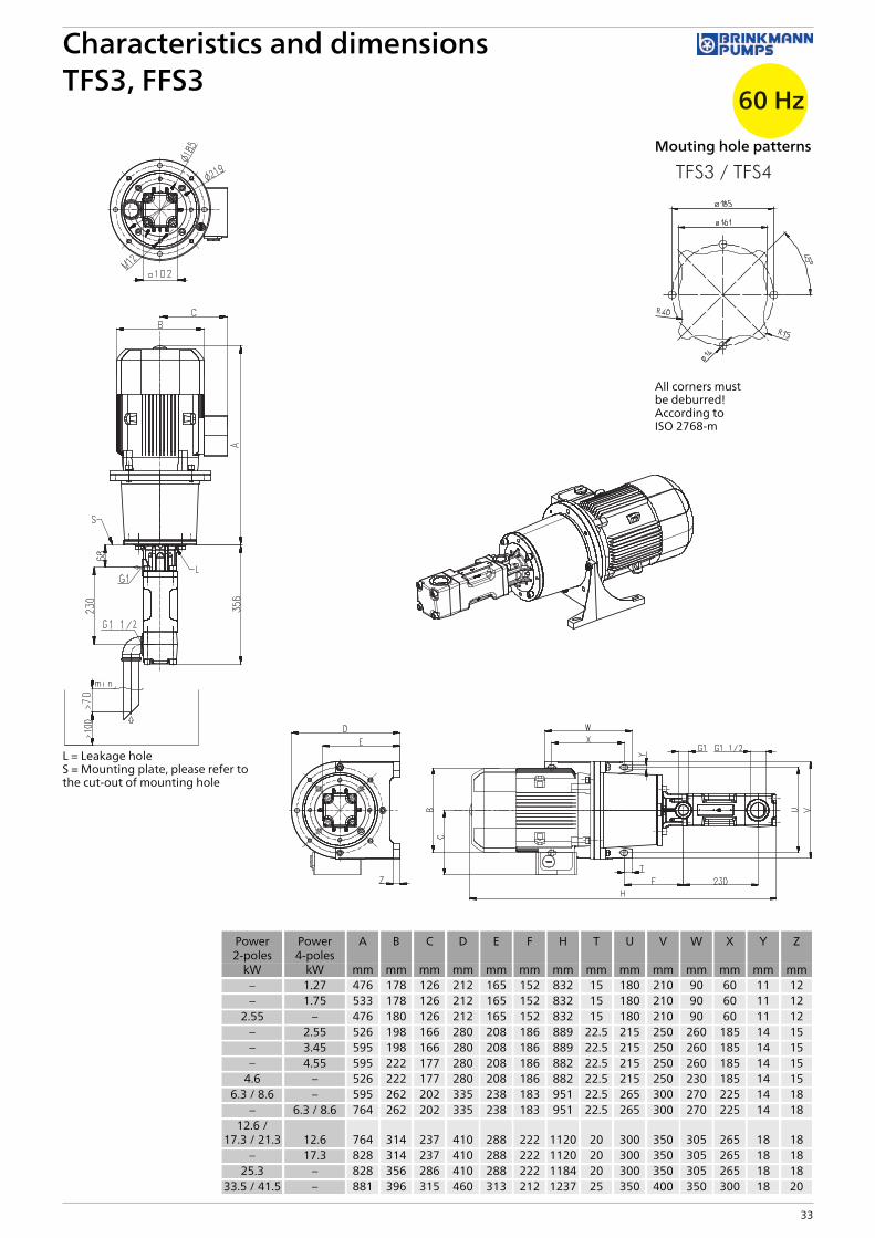
TFS376/ QTh1) 122.5 – – – – QTh
1) 61.3 – – – –
10 116.2 119.5 2.5 2.8 6.3 73 55 58.3 1.2 1.3 1.75 4620 114.1 118.3 4.6 4.9 8.6 86 52.8 57.1 2.2 2.4 3.45 5830 112 117.2 6.6 7.1 8.6 86 50.8 55.9 3.3 3.5 4.55 6540 110 116.1 8.7 9.2 12.6 104 48.7 54.9 4.3 4.6 6.3 7550 108 115.1 10.7 11.3 12.6 104 46.7 53.8 5.3 5.7 6.3 7560 106 114.1 12.8 13.5 17.3 113 44.8 52.9 6.3 6.7 8.6 9070 104.1 113.2 14.8 15.6 17.3 113 42.8 51.9 7.3 7.8 8.6 9080 102.2 112.3 16.8 17.8 21.3 133 40.9 51 8.4 8.9 12.6 11290 100.3 111.4 18.9 19.9 21.3 133 38.9 50.2 9.4 10.0 12.6 112
100 98.5 110.6 20.9 22.0 25.3 162 37 49.4 10.4 11.1 12.6 112110 95.5 109.9 23.0 24.2 33.5 219 - 48.6 - 12.2 17.3 138120 92.6 109.2 25.0 26.3 33.5 219 - 48 - 13.3 17.3 138130 89.8 107.4 27.1 28.5 33.5 219 – – – – – –140 87 105.7 29.1 30.6 33.5 219 – – – – – –150 84.2 104 31.1 32.7 41.5 248 – – – – – –
1) QTh: Theoretical flow rateHigher pressures (up to 200 bar) upon request.Viscosity > 20 mm2/s more power consumption.
High Pressure PumpsTFS3, FFS3Screw spindles
60 Hz
32
L = Leakage holeS = Mounting plate, please refer tothe cut-out of mounting hole
Mouting hole patterns
All corners mustbe deburred!According toISO 2768-m
Characteristics and dimensionsTFS3, FFS3
60 Hz
33
Power2-poles
Power4-poles
A B C D E F H T U V W X Y Z
kW kW mm mm mm mm mm mm mm mm mm mm mm mm mm mm– 1.27 476 178 126 212 165 152 832 15 180 210 90 60 11 12– 1.75 533 178 126 212 165 152 832 15 180 210 90 60 11 12
2.55 – 476 180 126 212 165 152 832 15 180 210 90 60 11 12– 2.55 526 198 166 280 208 186 889 22.5 215 250 260 185 14 15– 3.45 595 198 166 280 208 186 889 22.5 215 250 260 185 14 15– 4.55 595 222 177 280 208 186 882 22.5 215 250 260 185 14 15
4.6 – 526 222 177 280 208 186 882 22.5 215 250 230 185 14 156.3 / 8.6 – 595 262 202 335 238 183 951 22.5 265 300 270 225 14 18
– 6.3 / 8.6 764 262 202 335 238 183 951 22.5 265 300 270 225 14 1812.6 /
17.3 / 21.3 12.6 764 314 237 410 288 222 1120 20 300 350 305 265 18 18– 17.3 828 314 237 410 288 222 1120 20 300 350 305 265 18 18
25.3 – 828 356 286 410 288 222 1184 20 300 350 305 265 18 1833.5 / 41.5 – 881 396 315 460 313 212 1237 25 350 400 350 300 18 20

2-pole motorrotation speed 3500 RPM
4-pole motorrotation speed 1750 RPM
Pressuremax.
Flow at viscosity Power consump-tion at viscosity
Motor Weight Flow at viscosity Power consump-tion at viscosity
Motor Weight
1mm²/s
20mm²/s
1mm²/s
20mm²/s
1mm²/s
20mm²/s
1mm²/s
20mm²/s
Type / bar l/min l/min kW kW kW kg l/min l/min kW kW kW kg
TFS460/ QTh1) 151.2 – – – – QTh
1) 75.6 – – – –
10 144 147 3.3 3.7 4.6 74 68 72 1.6 1.6 2.55 6420 141 146 5.8 6.4 8.6 96 65 70 2.8 2.9 3.45 6430 138 144 8.4 9.0 12.6 115 63 69 4.1 4.3 4.55 7640 136 143 10.9 11.7 12.6 115 60 67 5.3 5.6 6.3 8550 133 142 13.4 14.4 17.3 124 57 66 6.6 7.0 8.6 10060 131 140 15.9 17.0 21.3 144 55 65 7.9 8.4 8.6 10070 128 139 18.4 19.7 21.3 144 53 63 9.1 9.7 12.6 12380 126 138 21.0 22.3 25.3 173 50 62 10.4 11.1 12.6 12390 124 137 23.5 25.0 33.5 230 48 61 11.6 12.4 17.3 149
100 122 136 26.0 27.7 33.5 230 45 60 12.9 13.8 17.3 149110 120 135 28.5 30.3 33.5 230 - 59 - 15.2 17.3 149120 117 134 31.1 33.0 41.5 259 - 58 - 16.5 17.3 149
TFS480/ QTh1) 201.7 – – – – QTh
1) 100.8 – – – –
10 192 197 4.2 4.9 6.3 83 91 96 2.0 2.1 2.55 6420 188 194 7.5 8.5 12.6 115 87 94 3.7 3.9 4.55 7630 184 192 10.9 12.1 17.3 124 84 91 5.3 5.7 6.3 8540 181 190 14.2 15.6 17.3 124 80 89 7.0 7.5 8.6 10050 178 188 17.6 19.2 21.3 144 77 88 8.7 9.3 12.6 12360 175 187 21.0 22.8 25.3 173 74 86 10.4 11.1 12.6 12370 172 185 24.3 26.4 33.5 230 71 84 12.1 12.9 17.3 14980 169 183 27.7 30.0 33.5 230 68 83 13.7 14.7 17.3 14990 166 182 31.1 33.6 41.5 259 65 81 15.4 16.5 17.3 149
100 164 181 34.4 37.1 41.5 259 62 80 17.1 18.3 21.3 168110 161 180 37.8 40.7 41.5 259 - 79 - 20.1 21.3 168120 158 179 41.1 44.3 51.0 374 - 78 - 21.9 25.3 188
TFS496/ QTh1) 242 – – – – QTh
1) 121 – – – –
10 231 235 4.8 5.6 8.6 96 110 114 2.3 2.7 3.45 6420 226 233 8.9 9.9 12.6 115 105 112 4.3 4.8 6.3 8530 222 231 12.9 14.2 17.3 124 101 110 6.3 7.0 8.6 10040 218 229 16.9 18.5 21.3 144 97 108 8.4 9.1 12.6 12350 214 227 21.0 22.8 25.3 173 93 106 10.4 11.3 12.6 12360 211 225 25.0 27.1 33.5 230 90 104 12.4 13.5 17.3 14970 207 224 29.0 31.4 33.5 230 86 103 14.4 15.6 17.3 14980 204 222 33.1 35.7 41.5 259 83 101 16.4 17.8 21.3 16890 201 220 37.1 40.0 41.5 259 79 99 18.4 19.9 21.3 168
100 198 219 41.1 44.3 51.0 374 76 98 20.5 22.1 25.3 188110 195 217 45.2 48.6 51.0 374 - 96 - 24.3 34.5 244120 191 215 49.2 52.9 62.0 469 - 94 - 26.4 34.5 244
1) QTh: Theoretical flow rateViscosity > 20 mm2/s more power consumption.
High Pressure PumpsTFS4, FFS4Screw spindles
60 Hz
34

L = Leakage holeS = Mounting plate, please refer tothe cut-out of mounting hole
Mounting holepatterns
All corners mustbe deburred!According toISO 2768-m
Characteristics and dimensionsTFS4, FFS4
60 Hz
35
Power2-poles
Power4-poles
A B C D E F H T U V W X Y Z
kW kW mm mm mm mm mm mm mm mm mm mm mm mm mm mm– 2.55 / 3.45 533 198 166 280 218 188 934 22.5 215 250 230 185 14 15
4.6 4.55 526 222 177 280 218 188 927 22.5 215 250 230 185 14 156.3 / 8.6 6.3 / 8.6 609 262 202 335 248 199 1010 22.5 265 300 270 225 14 18
12.6 /17.3 / 21.3 12.6 / 17.3 764 314 237 410 298 224 1165 20 300 350 305 265 18 18
25.3 21.3 828 356 286 410 298 224 1229 20 300 350 305 265 18 18– 25.3 858 356 286 410 298 224 1259 20 300 350 305 265 18 18
33.5 / 41.5 34.5 881 396 315 460 323 214 1282 25 350 400 350 300 18 2051.0 – 986 449 338 450 288 495 1387 25 356 436 361 311 19 3462.0 – 1056 497 410 525 313 547 1457 30 406 490 409 349 24 40
2-pole motorrotation speed 3500 RPM
4-pole motorrotation speed 1750 RPM
Pressuremax.
Flow at viscosity Power consump-tion at viscosity
Motor Weight Flow at viscosity Power consump-tion at viscosity
Motor Weight
1mm²/s
20mm²/s
1mm²/s
20mm²/s
1mm²/s
20mm²/s
1mm²/s
20mm²/s
Type / bar l/min l/min kW kW kW kg l/min l/min kW kW kW kg
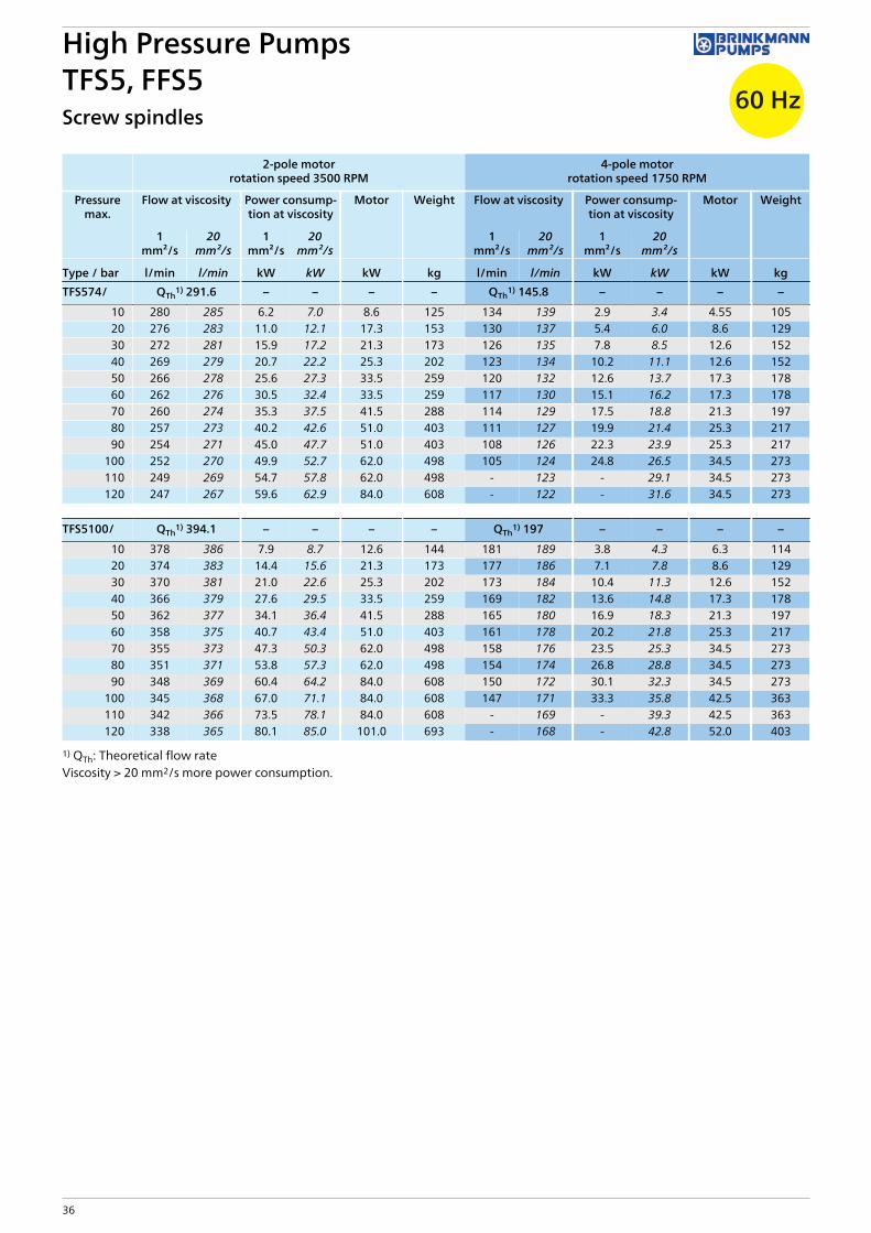
TFS574/ QTh1) 291.6 – – – – QTh
1) 145.8 – – – –
10 280 285 6.2 7.0 8.6 125 134 139 2.9 3.4 4.55 10520 276 283 11.0 12.1 17.3 153 130 137 5.4 6.0 8.6 12930 272 281 15.9 17.2 21.3 173 126 135 7.8 8.5 12.6 15240 269 279 20.7 22.2 25.3 202 123 134 10.2 11.1 12.6 15250 266 278 25.6 27.3 33.5 259 120 132 12.6 13.7 17.3 17860 262 276 30.5 32.4 33.5 259 117 130 15.1 16.2 17.3 17870 260 274 35.3 37.5 41.5 288 114 129 17.5 18.8 21.3 19780 257 273 40.2 42.6 51.0 403 111 127 19.9 21.4 25.3 21790 254 271 45.0 47.7 51.0 403 108 126 22.3 23.9 25.3 217
100 252 270 49.9 52.7 62.0 498 105 124 24.8 26.5 34.5 273110 249 269 54.7 57.8 62.0 498 - 123 - 29.1 34.5 273120 247 267 59.6 62.9 84.0 608 - 122 - 31.6 34.5 273
TFS5100/ QTh1) 394.1 – – – – QTh
1) 197 – – – –
10 378 386 7.9 8.7 12.6 144 181 189 3.8 4.3 6.3 11420 374 383 14.4 15.6 21.3 173 177 186 7.1 7.8 8.6 12930 370 381 21.0 22.6 25.3 202 173 184 10.4 11.3 12.6 15240 366 379 27.6 29.5 33.5 259 169 182 13.6 14.8 17.3 17850 362 377 34.1 36.4 41.5 288 165 180 16.9 18.3 21.3 19760 358 375 40.7 43.4 51.0 403 161 178 20.2 21.8 25.3 21770 355 373 47.3 50.3 62.0 498 158 176 23.5 25.3 34.5 27380 351 371 53.8 57.3 62.0 498 154 174 26.8 28.8 34.5 27390 348 369 60.4 64.2 84.0 608 150 172 30.1 32.3 34.5 273
100 345 368 67.0 71.1 84.0 608 147 171 33.3 35.8 42.5 363110 342 366 73.5 78.1 84.0 608 - 169 - 39.3 42.5 363120 338 365 80.1 85.0 101.0 693 - 168 - 42.8 52.0 403
1) QTh: Theoretical flow rateViscosity > 20 mm2/s more power consumption.
High Pressure PumpsTFS5, FFS5Screw spindles
60 Hz
36

L = Leakage holeS = Mounting plate, please refer tothe cut-out of mounting hole
Mounting hole patterns
All corners mustbe deburred!According toISO 2768-m
Characteristics and dimensionsTFS5, FFS5
60 Hz
37
Power2-poles
Power4-poles
A B C D F H T U V W X Y Z
kW kW mm mm mm mm mm mm mm mm mm mm mm mm mm– 4.55 556 222 177 280 228 1051 22.5 215 250 230 185 14 15
8.6 6.3 / 8.6 622 262 202 335 222 1117 22.5 265 300 270 225 14 1812.6 /
17.3 / 21.3 12.6 / 17.3 767 314 237 410 237 1262 20 300 350 305 265 18 1825.3 21.3 831 356 286 410 237 1326 20 300 350 305 265 18 18
– 25.3 861 356 286 410 237 1356 20 300 350 305 265 18 1833.5 / 41.5 34.5 884 396 315 460 227 1379 25 350 400 350 300 18 20
– 42.5 927 449 338 520 223 1422 25 400 450 385 335 18 2051.0 – 989 449 338 450 508 1484 25 356 436 361 311 19 34
– 52.0 987 449 338 450 508 1482 25 356 436 361 311 19 3462.0 – 1059 497 410 525 560 1554 30 406 490 409 349 24 4084.0 – 1135 551 433 555 582 1630 55.5 457 540 479 368 24 40
101.0 – 1135 551 433 555 582 1630 30 457 540 479 419 24 40

2-pole motorrotation speed 3500 RPM
4-pole motorrotation speed 1750 RPM
Pressuremax.
Flow at viscosity Power consump-tion at viscosity
Motor Weight Flow at viscosity Power consump-tion at viscosity
Motor Weight
1mm²/s
20mm²/s
1mm²/s
20mm²/s
1mm²/s
20mm²/s
1mm²/s
20mm²/s
Type / bar l/min l/min kW kW kW kg l/min l/min kW kW kW kg
TFS5120/ QTh1) 472.9 – – – – QTh
1) 236.4 – – – –
10 453 463 9.2 10.0 12.6 144 217 227 4.4 5.0 6.3 11420 447 460 17.1 18.4 21.3 173 211 223 8.4 9.2 12.6 15230 442 457 24.9 26.7 33.5 259 205 220 12.3 13.4 17.3 17840 436 454 32.8 35.1 41.5 288 200 218 16.3 17.6 21.3 19750 431 452 40.7 43.5 51.0 403 195 215 20.2 21.8 25.3 21760 426 449 48.6 51.9 62.0 498 190 213 24.1 26.1 34.5 27370 421 447 56.5 60.2 62.0 498 185 210 28.1 30.3 34.5 27380 417 445 64.3 68.6 84.0 608 180 208 32.0 34.5 42.5 36390 412 443 72.2 77.0 84.0 608 175 206 36.0 38.7 42.5 363
100 408 441 80.1 85.4 101.0 693 170 205 39.9 42.9 52.0 403110 403 440 88.0 93.7 101.0 693 - 203 - 47.1 52.0 403120 399 438 95.8 102.1 123.0 868 - 202 - 51.3 63.0 468
TFS5130/ QTh1) 512.3 – – – – QTh
1) 256.1 – – – –
10 491 500 9.8 11.7 17.3 153 235 243 4.8 5.4 6.3 11420 484 495 18.4 20.3 25.3 202 228 239 9.0 9.8 12.6 15230 477 490 26.9 29.0 33.5 259 221 234 13.3 14.2 17.3 17840 471 486 35.5 37.6 41.5 288 215 230 17.6 18.6 25.3 21750 465 482 44.0 46.2 51.0 403 209 225 21.8 23.0 25.3 21760 459 477 52.5 54.8 62.0 498 203 221 26.1 27.3 34.5 27370 454 474 61.1 63.5 84.0 608 198 217 30.4 31.7 34.5 27380 449 470 69.6 72.1 84.0 608 193 214 34.7 36.1 42.5 36390 444 466 78.1 80.7 84.0 608 187 210 38.9 40.5 52.0 403
100 440 463 86.7 89.3 101.0 693 182 207 43.2 44.9 52.0 403110 - 460 - 98.0 123.0 868 - 204 - 49.3 63.0 468120 - 457 - 106.6 123.0 868 - 201 - 53.7 63.0 468
1) QTh: Theoretical flow rateViscosity > 20 mm2/s more power consumption.
High Pressure PumpsTFS5, FFS5Screw spindles
60 Hz
38

L = Leakage holeS = Mounting plate, please refer tothe cut-out of mounting hole
Mounting hole patterns
All corners mustbe deburred!According toISO 2768-m
Characteristics and dimensionsTFS5, FFS5
60 Hz
39
Power2-poles
Power4-poles
A B C D F H T U V W X Y Z
kW kW mm mm mm mm mm mm mm mm mm mm mm mm mm– 6.3 622 262 202 335 222 1117 22.5 265 300 270 225 14 18
12.6 /17.3 / 21.3 12.6 / 17.3 767 314 237 410 237 1262 20 300 350 305 265 18 18
25.3 21.3 831 356 286 410 237 1326 20 300 350 305 265 18 18– 25.3 861 356 286 410 237 1356 20 300 350 305 265 18 18
33.5 / 41.5 34.5 884 396 315 460 227 1379 25 350 400 350 300 18 20– 42.5 927 449 338 520 223 1422 25 400 450 385 335 18 20
51.0 – 989 449 338 450 508 1484 25 356 436 361 311 19 34– 52.0 987 449 338 450 508 1482 25 356 436 361 311 19 34
62.0 63.0 1059 497 410 525 560 1554 30 406 490 409 349 24 4084.0 – 1135 551 433 555 582 1630 55.5 457 540 479 368 24 40
101.0 – 1135 551 433 555 582 1630 30 457 540 479 419 24 40123.0 – 1239 616 515 645 623 1734 35 508 610 527 406 28 50

2-pole motorrotation speed 3500 RPM
4-pole motorrotation speed 1750 RPM
Pressuremax.
Flow at viscosity Power consump-tion at viscosity
Motor Weight Flow at viscosity Power consump-tion at viscosity
Motor Weight
1mm²/s
20mm²/s
1mm²/s
20mm²/s
immersionversion
1mm²/s
20mm²/s
1mm²/s
20mm²/s
Type / bar l/min l/min kW kW kW kg l/min l/min kW kW kW kg
TFS690/ QTh1) 554 – – – – QTh
1) 277 – – – –
10 540 545 11.6 13.3 17.3 213 263 268 5.6 6.2 8.6 19020 532 540 20.9 22.6 25.3 262 255 263 10.2 10.8 12.6 21230 524 535 30.1 31.8 33.5 319 247 258 14.9 15.5 17.3 23840 516 531 39.3 41.0 51.0 464 239 254 19.5 20.1 25.3 27750 509 527 48.6 50.3 62.0 559 232 250 24.1 24.7 34.5 33360 502 523 57.8 59.5 62.0 559 225 246 28.7 29.3 34.5 33370 496 519 67.0 68.7 84.0 669 219 242 33.3 33.9 42.5 42480 490 515 76.3 78.0 84.0 669 213 238 37.9 38.5 42.5 424
TFS6120/ QTh1) 739 – – – – QTh
1) 369 – – – –
10 720 726 14.7 16.4 21.3 233 351 357 7.2 7.8 12.6 21220 710 721 27.0 28.7 33.5 319 341 351 13.3 13.9 17.3 23830 701 715 39.3 41.0 51.0 464 331 346 19.5 20.1 21.3 25740 692 710 51.6 53.3 62.0 559 322 340 25.6 26.2 34.5 33350 683 704 64.0 65.7 84.0 669 314 335 31.8 32.4 34.5 33360 676 699 76.3 78.0 84.0 669 306 330 37.9 38.5 42.5 42470 668 695 88.6 90.3 101.0 754 299 325 44.1 44.7 52.0 46480 659 689 101.0 103.0 123.0 929 290 320 50.2 50.8 63.0 529
TFS6145/ QTh1) 893 – – – – QTh
1) 446 – – – –
10 870 878 17.3 19.0 25.3 262 424 432 8.4 9.0 12.6 21220 857 868 32.2 33.9 41.5 348 411 422 15.9 16.5 21.3 25730 845 859 47.0 48.7 62.0 559 398 413 23.3 23.9 34.5 33340 833 851 61.9 63.6 84.0 669 386 405 30.8 31.4 34.5 33350 822 844 76.8 78.5 84.0 669 375 397 38.2 38.8 42.5 42460 811 837 91.7 93.4 101.0 754 365 391 45.6 46.2 52.0 46470 799 829 106.6 108.3 123.0 929 353 382 53.1 53.7 63.0 529
1) QTh: Theoretical flow rateViscosity > 20 mm2/s more power consumption.All 6 series screw pumps with an operating flow rate of 800 l/min or above must be operated with a feed pump which supplies fluidwith at least 1bar of pressure to the pump inlet.
High Pressure PumpsTFS6, FFS6Screw spindles
60 Hz
40

L = Leakage holeS = Mounting plate, please refer tothe cut-out of mounting hole
Mounting hole patterns
All corners mustbe deburred!According toISO 2768-m
Characteristics and dimensionsTFS6, FFS6
60 Hz
41
Power2-poles
Power4-poles
A B C D F H T U V W X Y Z
kW kW mm mm mm mm mm mm mm mm mm mm mm mm mm– 8.6 673 262 202 335 252 1292 22.5 265 300 270 225 14 18
17.3 / 21.3 12.6 795 314 237 410 252 1414 20 300 350 305 265 18 18– 17.3 795 314 237 410 265 1414 20 300 350 305 265 18 18– 21.3 859 356 286 410 265 1478 20 300 350 305 265 18 18
25.3 – 859 356 286 410 252 1478 20 300 350 305 265 18 18– 25.3 889 356 286 410 397 1508 20 300 350 305 265 18 18
33.5 / 41.5 – 910 396 315 460 265 1529 25 350 400 350 300 18 20– 34.5 910 396 315 460 417 1529 25 350 400 350 300 18 20– 42.5 973 449 338 520 432 1592 25 400 450 385 335 18 20
51.0 – 1015 449 338 450 546 1634 25 356 436 361 311 19 34– 52.0 1013 449 338 450 546 1632 25 356 436 361 311 19 34
62.0 – 1072 497 410 525 585 1691 30 406 490 409 349 24 40– 63.0 1087 497 410 525 600 1706 30 406 490 409 349 24 40
84.0 – 1163 551 433 555 622 1782 55.5 457 540 479 368 24 40101.0 – 1163 551 433 555 622 1782 30 457 540 479 419 24 40

42 Subject to alteration
AccessoriesValves
Adjustable Pressure Relief Valves
Adjustable pressure relief valves allow for variable operating pressures anywhere between 5 – 120 bar. In order to prevent overloading of the motor, however, the maximum operating pressure may never exceed the highest allowable operating pressure for the specific pump and motor combination in use. The system user must ensure that the operating pressure never exceeds the highest allowable operating pressure (i.e. by using a second non adjustable pressure relief valve which is set for the highest allowable pressure).
Type Pressurep (bar)
FlowQmax (l/min)
3 – HPB – 08 10 – 200 18
3 – HPB – S 15 5 – 64 100
3 – HPB – H 15 5 – 120 100
3 – HPB – S 32 5 – 64 400
3 – HPB – H 32 5 – 120 240
3 – HPB – S 50 5 – 64 800
SPB Series SPB Series pressure relief valves are electronically adjustable valves. The valve requires an analog signal of 0 – 10 V. The ratio between the control voltage and the operating pressure is 1:10 and 1:18.5. Without power and air supply the valve is fully open and in dump mode.
Type Pressurep (bar)
FlowQmax (l/min)
SPB – 08 10 – 200 18
SPB – S 15 5 – 64 100
SPB – H 15 5 – 120 100
SPB – S 32 5 – 64 400
SPB – H 32 5 – 120 240
SPB – S 50 5 – 64 800
Type3–HPB
amm
bmm
cmm
dmm
emm
fmm
gmm
08 180 37 138 G3/8 Ø 74 – –
S / H 15 186 40 97 G1 * 80 116.3 89
S / H 32 231 60 160 G11/2 * 120 125 109
S 50 251 70 160 G11/2 * 140 – –
TypeSPB
amm
bmm
cmm
dmm
emm
fmm
08 151 37 138 G3/8 Ø 74 –
S / H 15 162 40 97 G1 * 80 150.5
S / H 32 192.5 60 160 G11/2 * 120 176.5
S 50 251 70 160 G11/2 * 140 –
3-HPB Series The 3-HPB series are manually adjustable pressure relief valves. The valves are pneumatically operated and control the operat-ing pressure with the control pressure in a ratio of 1:10 and 1:18.5. Without power and air supply the valve is fully open and in dump mode.
Further valves on request.

43Subject to alteration
AccessoriesValves
Control pressure diagram Control pressure diagram Control pressure diagram
Depressurized recirculation mode Depressurized recirculation mode Depressurized recirculation mode
Control pressure diagram Control pressure diagram Control pressure diagram
Depressurized recirculation mode Depressurized recirculation mode Depressurized recirculation mode
3-HPB – 08 | SPB – 08 3 – HPB – S 15 | SPB – S 15 3 – HPB – H 15 | SPB – H 15
3 – HPB – S 32 | SPB – S 32 3 – HPB – H 32 | SPB – H 32 3 – HPB – S 50 | SPB – S 50
Medium pressure [bar]
Con
trol p
ress
ure
[bar
]
Model 10 – 200 bar
20020 40 60 80 100 120 140 160 180
Approved control pressure range
1
0
2
3
4
5
6
2
3
4
5
6
7
8
9
10
Medium pressure [bar]
Con
trol p
ress
ure
[bar
]
Model 5 – 64 bar
605040302010
1
0
2
3
4
5
6
2
3
4
5
6
7
8
9
10
Approved control pressure range
Medium pressure [bar]
Con
trol p
ress
ure
[bar
]
Model 5 – 120 bar
1
0
2
3
4
5
6
2
3
4
5
6
7
8
9
10
10 20 30 40 50 60 70 80 90 100 110 120
Approved control pressure range
Flow rate [m³/h]
Rem
aini
ng p
ress
ure
[bar
]
Model 10 – 200 bar1,25
0
0,25
0,5
0,75
1
0,5 1,0 1,5
Flow rate [m³/h]
Rem
aini
ng p
ress
ure
[bar
]
Model 5 – 64 bar
0 1 1,5 2 2,5 3 3,5 4 4,5 5 5,5 60,5
1
2
3
4
5
6
7
8
9
Flow rate [m³/h]
Rem
aini
ng p
ress
ure
[bar
]
Model 5 – 120 bar
0 1 1,5 2 2,5 3 3,5 4 4,5 5 5,5 60,5
1
2
3
4
5
6
7
8
9
Medium pressure [bar]
Con
trol p
ress
ure
[bar
]
Model 5 – 64 bar
605040302010
1
0
2
3
4
5
6
2
3
4
5
6
7
8
9
10
Approved control pressure range
Medium pressure [bar]
Con
trol p
ress
ure
[bar
]
Model 5 – 120 bar
1
0
2
3
4
5
6
2
3
4
5
6
7
8
9
10
10 20 30 40 50 60 70 80 90 100 110 120
Approved control pressure range
Medium pressure [bar]
Con
trol p
ress
ure
[bar
]
Model 5 – 64 bar
605040302010
1
0
2
3
4
5
6
2
3
4
5
6
7
8
9
10
Approved control pressure range
Flow rate [m³/h]
Rem
aini
ng p
ress
ure
[bar
]
Model 5 – 64 bar
0
1
2
3
4
5
6
7
8
9
3 6 9 12 15 18 21 24
Flow rate [m³/h]
Rem
aini
ng p
ress
ure
[bar
]
Model 5 – 120 bar
0
1
2
3
4
5
6
7
8
9
3 6 9 12 15
Flow rate [m³/h]
Rem
aini
ng p
ress
ure
[bar
]
Model 5 – 64 bar
0
1
2
3
4
5
6
7
8
9
6 12 18 24 30 36 42 48

44 Subject to alteration
Accessories
Non-adjustable Pressure Relief Valves
Non-adjustable Pressure Relief Valves BBV Non-adjustable Pressure Relief valves of the series BBV are shock absorbent valves which open at a preset pressure. The relief valve opens at the factory set pressure which is available in 10 bar increments and the excess flow rate is diverted through a separate bypass line back into the tank.
Screw spindle pumps are positive displacement pumps which always require the installation of a pressure relief valve in order to pre-vent bursting. Pressure relief valves are set for a maximum operating pressure and protect the pump motor from overloading. Once the set maximum pressure is reached, the relief valve opens and the excess flow rate is passed through the valve back into the tank.
In order to avoid pressure spikes in the system a pressure relief valve which cushions against vibration is recommended. BBV 1 – 3 series are such relief valves. They are available in 10 bar increments and are preset by the factory for the highest allowable operating pressure for the specific pump and motor combination.
Additional relief valve characteristics upon request. The actual opening pressure may deviate from the nominal pressure setting of the valve because of the tension of the loaded spring rate.
Above mentioned pressure relief valves are available upon request in a adjustable version. The system user must ensure that the operating pressure never exceeds the highest allowable operating pressure (i.e. by using a second non adjustable pressure relief valve which is set for the highest allowable pressure).
Valves
Ordering description: e.g. BBV 3 / 50
BBV 1 + 2 mm
BBV 3 mm
a 100.5 130
b 41.5 53
c 50 65
d G ¾ G1
e 52 81
f 45 49
g 70 81.5
h 36 42
Pressure (bar)
Type of Pumps Type of Valves 10 20 30 40 50 60 70 80 90 100 110 120 130 140 150
BFS1, FFS1BFS232, FFS232
BBV 1 l l l l l l l l l l l l l l l
BFS2, FFS2 BBV 2 l l l l l l l l l l l l l l l
TFS2, FFS3 BBV 3 l l l l l l l l l l l l l l l

45Subject to alteration
AccessoriesPressure gauge / Suction protectionG4 Version
Pressure gauge G4 Version
Suction protection
The patented suction protection prevents large particles (and foreign objects) from entering the screw pump‘s suction.
G1/8“ BFS/FFS 1, 2 G1/4“ TFS/FFS 3, 4, 5
Depressurized leakage return to tank
SAE flange
TypePressurep (bar)
M 60 0 – 60
M 100 0 – 100
M 160 0 – 160
Type Type of PumpsA
mmB
mmØ D
AS1-2 BFS1, BFS2 90 94 1“
AS3 TFS3 115 129 1½“
AS4 TFS4 150 175 2“
AS5 TFS5 195 190 2½“
AS1-2-H BFS1, BFS2 90 60 1“
AS3H TFS3 115 115 G1½“
AS4H TFS4 153 175 G2“
AS5H TFS5 194 190 G2½“
Type Type of PumpsA
mmB
mm
SAE 2 ½ TFS5, FFS5 88.9 50.8
SAE 3 TFS6, FFS6 120.6 69.8
AS AS-H
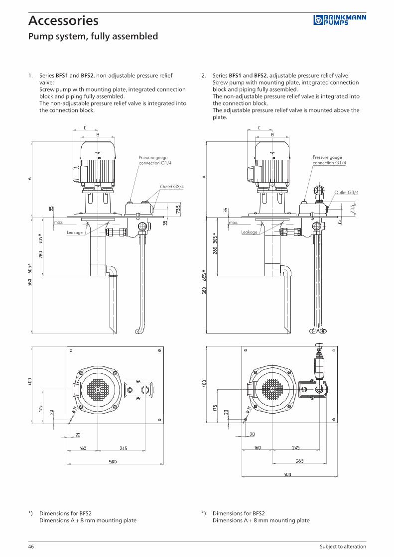
46 Subject to alteration
AccessoriesPump system, fully assembled
1. Series BFS1 and BFS2, non-adjustable pressure relief valve: Screw pump with mounting plate, integrated connection block and piping fully assembled. The non-adjustable pressure relief valve is integrated into the connection block.
2. Series BFS1 and BFS2, adjustable pressure relief valve: Screw pump with mounting plate, integrated connection block and piping fully assembled. The non-adjustable pressure relief valve is integrated into the connection block. The adjustable pressure relief valve is mounted above the plate.
*) Dimensions for BFS2 Dimensions A + 8 mm mounting plate
*) Dimensions for BFS2 Dimensions A + 8 mm mounting plate

47Subject to alteration
AccessoriesPump system, fully assembled
3. Series TFS3, non adjustable pressure relief valve: Screw pump with mounting plate, integrated connection block and piping fully assembled. The non-adjustable pressure relief valve is integrated into the connection block.
4. Series TFS3, adjustable pressure relief valve: Screw pump with mounting plate, integrated connection block and piping fully assembled. The non-adjustable pressure relief valve is integrated into the connection block. The adjustable pressure relief valve is mounted above the plate.
Dimensions A + 8 mm mounting plate Dimensions A + 8 mm mounting plate

48 Subject to alteration
AccessoriesPump system, fully assembled
5. Series TFS4 and TFS5, adjustable pressure relief valve (pneumatically operated): Screw pump with mounting plate, adjustable pressure relief valve (pneumatically operated) and piping fully assembled. The adjustable pressure relief valve is mounted above the plate.
6. Series TFS6, adjustable pressure relief valve: Screw pump with mounting plate, adjustable pressure relief valve (pneumatically operated) and piping fully assembled. The adjustable pressure relief valve is mounted above the plate.
*) Dimensions for TFS5 **) Dimensions for motors larger than 37 kW upon request Dimensions A + 12 mm mounting plate

49
Questionnaire
Pump
Requirement per year (each)
Pumping data
Flow rate (l/min.)
Pressure (bar)
Dimensions
Immersion depth
Medium to be pumped
Coolants £
Oils £
Temperature (°C)
Viscosity at pumping temperature (mm2/s, cSt)
Density (kg/l)
pH value
Air in medium £ yes £ no
Lubricity in medium £ yes £ no
Filtration
Filtration (μm)
Filter type
ppm levels acc. to ISO 4406
Percentage of solids by weight (mg/l)
Motor
Protective system IP55
Insulation class (F)
Ambient temperature (°C)
Frequency control (Hz) from to
Switch-on operations (per min)
Motor connection plug HAN £ yes
Motor efficiency class £ IE2 £ IE3
Other
Field of application
Type Materials specific abrasion
£ grinding Al oxid £ cast iron £ tinder
£ grinding CBN £ brass £ diamond
£ drilling £ Al £ silicon carbide
£ turning £ steel
£ milling
£ other: £ other: £ other:
Contact details
Company
Address
Contact partner
Telephone
DateFax +49 2392 5006-180
E-Mail [email protected]
Drive
laid out for line power
£ 3 x 400 V, 50 Hz £ 3 x 440 V, 60 Hz £ 3 x 208-230 V, 60 Hz
£ 3 x 415 V, 50 Hz £ 3 x 460 V, 60 Hz £ 3 x 200-220 V, 60 Hz
£ 3 x 380 V, 50 Hz £ 3 x 480 V, 60 Hz £ 1 x 115 V, 60 Hz
£ 3 x 200 V, 50 Hz £ 3 x 380 V, 60 Hz £ other:
£ 1 x 230 V, 50 Hz £ 3 x 400 V, 60 Hz

50

Production
The combination of state of the art production equipment, along with lean manufacturing processes and a highly skilled and motivated work-force allows for the highest flexibility and availability of parts at the manu-facturing site in Werdohl, Germany. The US subsidiary located in Wixom, michigan was founded in 1997 and the Japanese subsidiary in kanagawa near Tokyo opened its doors in 2008.
it has always been a core philosophy of Brinkmann PumPs to be able to provide the highest level of service worldwide. In order to achieve this goal, all Brinkmann PumPs em-ployees globally go through rigorous training programs focusing on various areas, such as, pump applications, proper selection, consulting, service and repair.

BRINKMANN PUMPSK.H. Brinkmann GmbH & Co. KGFriedrichstraße 258791 WerdohlGermany
Tel. +49 2392 5006-0Fax +49 2392 [email protected]
Brinkmann Pumps Inc.47060 Cartier DriveWixom, MI 48393united states
Phone +1 248 926 9400Fax +1 248 926 [email protected] www.brinkmannpumps.com
Brinkmann Pumps Japan Co. Ltd.1-5-55, nishishindo, Hiratsuka Kanagawa, 254-0019 Japan
Phone +81 463 268391Fax +81 463 [email protected] www.brinkmannpumps.jp
EK 910-2.0-13.09 GB
The Brinkmann Pumps network – This is the way to find us.
Brinkmann PumPs has a global presence and direct representation throughout Europe, asia and North America. This ensures quick response times, competent consulting personnel and the highest level of service, which Brinkmann Pumps is known for, anytime and anywhere. Visit our website – where you will find all the contact details for our representative offices. Visit us and convince yourself of our capabilities.
Welcome to BRINKMANN PUMPS.