Screw feeding systems - Amazon S3 With either vibratory bowl feeder or sword feeder If feeding with...
16
Feeding Technology D 3820 E 07.2013 Screw feeding systems for handheld tools n Rationalised assembly n Process optimisation n High capacity n Ergonomic and convenient for the operator n Simple start-up Our screwfeeding systems consist of modules that are adapted to each other: one screwfeeder with integrated controller, a handheld screwdriver and all other add-on components that fit the customer‘s application. This proven system with an extreme high feed rate, allows a rational and process-opti- mized assembly. Screwdriving technology Automation Air motors Air tools
Transcript of Screw feeding systems - Amazon S3 With either vibratory bowl feeder or sword feeder If feeding with...
Feeding Technology
D 3820 E 07.2013
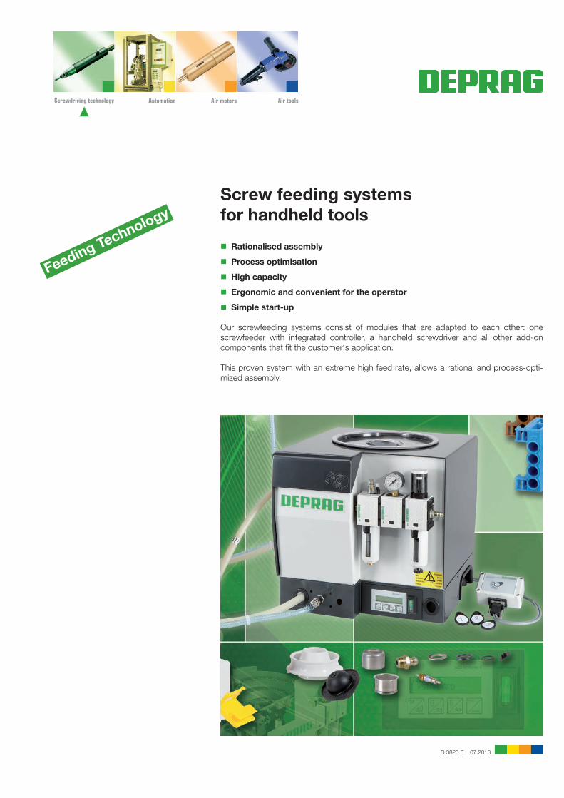
Screw feeding systemsfor handheld tools
n Rationalised assembly
n Process optimisation
n High capacity
n Ergonomic and convenient for the operator
n Simple start-up
Our screwfeeding systems consist of modules that are adapted to each other: one screwfeeder with integrated controller, a handheld screwdriver and all other add-on components that fit the customer‘s application.
This proven system with an extreme high feed rate, allows a rational and process-opti-mized assembly.
Screwdriving technology Automation Air motors Air tools
2
Size:0.15 l Feed volume Page 81.50 l Feed volume Page 8
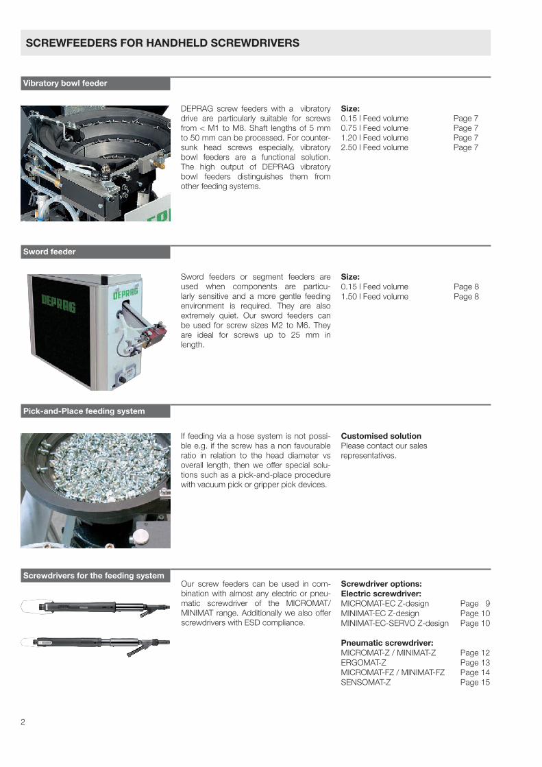
DEPRAG screw feeders with a vibratory drive are particularly suitable for screws from < M1 to M8. Shaft lengths of 5 mm to 50 mm can be processed. For counter-sunk head screws especially, vibratory bowl feeders are a functional solution. The high output of DEPRAG vibratory bowl feeders distinguishes them from other feeding systems.
Size:0.15 l Feed volume Page 70.75 l Feed volume Page 71.20 l Feed volume Page 72.50 l Feed volume Page 7
Screwdriver options:Electric screwdriver:MICROMAT-EC Z-design Page 9MINIMAT-EC Z-design Page 10MINIMAT-EC-SERVO Z-design Page 10
Pneumatic screwdriver:MICROMAT-Z / MINIMAT-Z Page 12ERGOMAT-Z Page 13MICROMAT-FZ / MINIMAT-FZ Page 14SENSOMAT-Z Page 15
If feeding via a hose system is not possi-ble e.g. if the screw has a non favourable ratio in relation to the head diameter vs overall length, then we offer special solu-tions such as a pick-and-place procedure with vacuum pick or gripper pick devices.
Customised solutionPlease contact our salesrepresentatives.
Our screw feeders can be used in com-bination with almost any electric or pneu-matic screwdriver of the MICROMAT/ MINIMAT range. Additionally we also offer screwdrivers with ESD compliance.
Sword feeders or segment feeders are used when components are particu-larly sensitive and a more gentle feeding environment is required. They are also extremely quiet. Our sword feeders can be used for screw sizes M2 to M6. They are ideal for screws up to 25 mm in length.
SCREWFEEDERS FOR HANDHELD SCREWDRIVERS
Vibratory bowl feeder
Sword feeder
Pick-and-Place feeding system
Screwdrivers for the feeding system
3
With either vibratory bowl feeder or sword feeder
If feeding with a hose system is not possible, we offer special solutions, such as the pick-and-place procedure
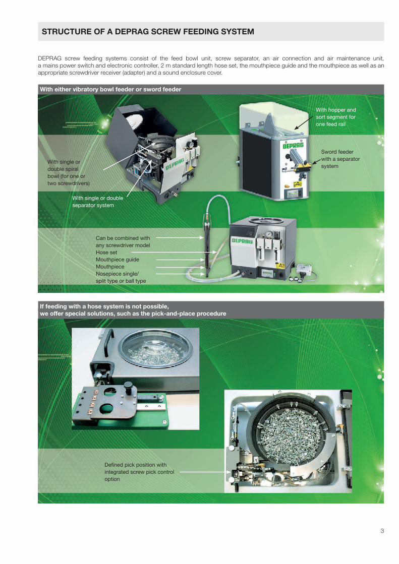
DEPRAG screw feeding systems consist of the feed bowl unit, screw separator, an air connection and air maintenance unit, a mains power switch and electronic controller, 2 m standard length hose set, the mouthpiece guide and the mouthpiece as well as an appropriate screwdriver receiver (adapter) and a sound enclosure cover.
With single ordouble spiralbowl (for one ortwo screwdrivers)
With single or doubleseparator system
With hopper andsort segment forone feed rail
Sword feeder with a separator system
Can be combined withany screwdriver modelHose setMouthpiece guideMouthpieceNosepiece single/split type or ball type
Defined pick position withintegrated screw pick controloption
STRUCTURE OF A DEPRAG SCREW FEEDING SYSTEM
4
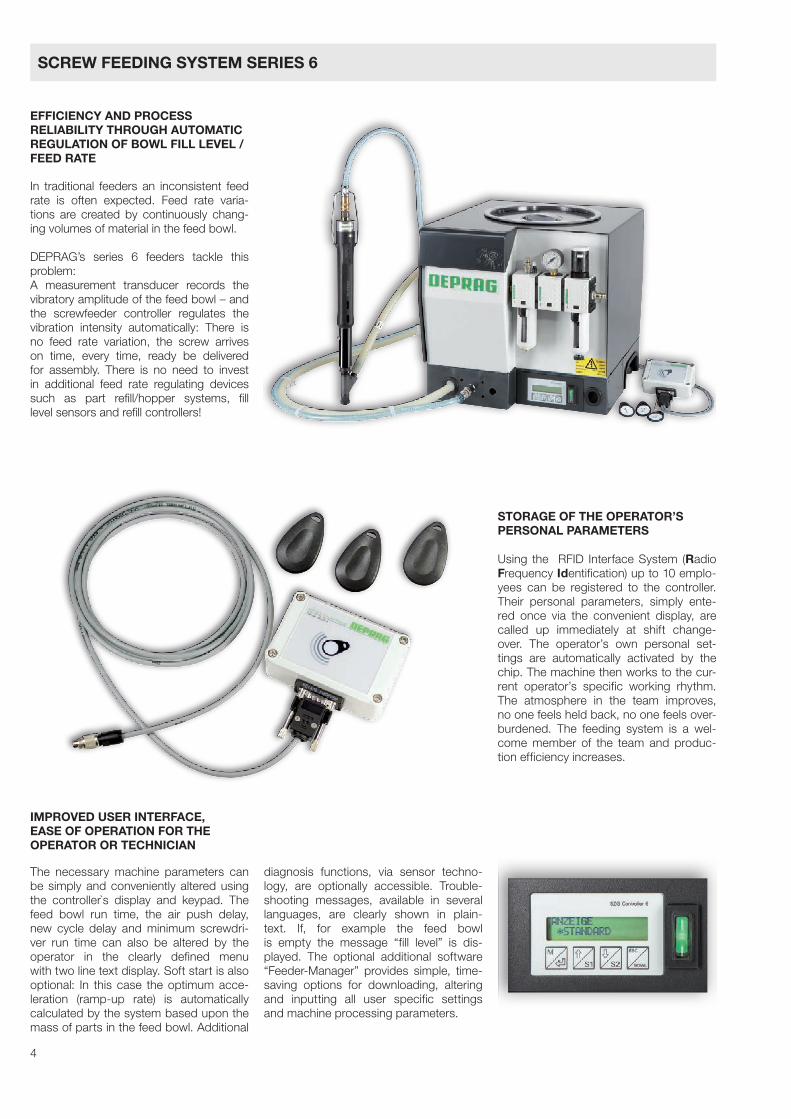
In traditional feeders an inconsistent feed rate is often expected. Feed rate varia-tions are created by continuously chang-ing volumes of material in the feed bowl.
DEPRAG’s series 6 feeders tackle this problem:A measurement transducer records the vibratory amplitude of the feed bowl – and the screwfeeder controller regulates the vibration intensity automatically: There is no feed rate variation, the screw arrives on time, every time, ready be delivered for assembly. There is no need to invest in additional feed rate regulating devices such as part refill/hopper systems, fill level sensors and refill controllers!
EFFICIENCY AND PROCESS RELIABILITY THROUGH AUTOMATIC REGULATION OF BOWL FILL LEVEL / FEED RATE
IMPROVED USER INTERFACE, EASE OF OPERATION FOR THEOPERATOR OR TECHNICIAN
The necessary machine parameters can be simply and conveniently altered using the controller`s display and keypad. The feed bowl run time, the air push delay, new cycle delay and minimum screwdri-ver run time can also be altered by the operator in the clearly defined menu with two line text display. Soft start is also optional: In this case the optimum acce-leration (ramp-up rate) is automatically calculated by the system based upon the mass of parts in the feed bowl. Additional
diagnosis functions, via sensor techno-logy, are optionally accessible. Trouble-shooting messages, available in several languages, are clearly shown in plain-text. If, for example the feed bowl is empty the message “fill level” is dis-played. The optional additional software “Feeder-Manager” provides simple, time- saving options for downloading, altering and inputting all user specific settings and machine processing parameters.
STORAGE OF THE OPERATOR’SPERSONAL PARAMETERS
Using the RFID Interface System (Radio Frequency Identification) up to 10 emplo-yees can be registered to the controller. Their personal parameters, simply ente-red once via the convenient display, are called up immediately at shift change- over. The operator’s own personal set-tings are automatically activated by the chip. The machine then works to the cur-rent operator’s specific working rhythm. The atmosphere in the team improves, no one feels held back, no one feels over-burdened. The feeding system is a wel-come member of the team and produc-tion efficiency increases.
SCREW FEEDING SYSTEM SERIES 6
5
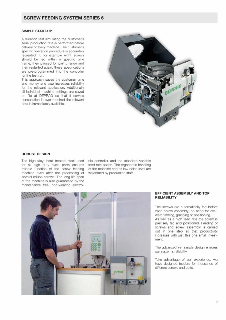
SIMPLE START-UP
A duration test simulating the customer’s serial production rate is performed before delivery of every machine. The customer’s specific operation procedure is accurately recreated. If, for example eight screws should be fed within a specific time frame, then paused for part change and then restarted again, these specifications are pre-programmed into the controller for the test run.This approach saves the customer time and money and also increases reliability for the relevant application. Additionally all individual machine settings are saved on file at DEPRAG so that if service consultation is ever required the relevant data is immediately available.
The high-alloy, heat treated steel used for all high duty cycle parts ensures reliable function of the screw feeding machine even after the processing of several million screws. The long life span of the machine is also guaranteed by the maintenance free, non-wearing electro-
nic controller and the standard variable feed rate option. The ergonomic handling of the machine and its low noise level are welcomed by production staff.
EFFICIENT ASSEMBLY AND TOP RELIABILITY
The screws are automatically fed before each screw assembly, no need for awk-ward fiddling, grasping or positioning.As well as a high feed rate the screw is precisely fed and positioned. Feeding of screws and screw assembly is carried out in one step so that productivity increases with just this one small invest-ment.
The advanced yet simple design ensures our system’s reliability.
Take advantage of our experience, we have designed feeders for thousands of different screws and bolts.
ROBUST DESIGN
SCREW FEEDING SYSTEM SERIES 6
6
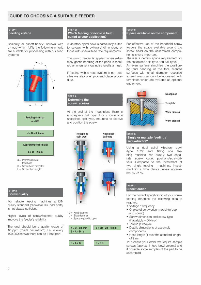
Basically all “shaft-heavy” screws with a head which fulfils the following criteria are suitable for processing with our feed systems:
For reliable feeding machines a DIN quality standard (allowable 3% bad parts) is not always sufficient.
Higher levels of screw/fastener quality improve the feeder`s reliability.
The goal should be a quality grade of 10 ppm (“parts per million“). I.e. in every 100,000 screws there can be 1 bad part.
A vibratory spiral bowl is particularly suitedto screws with awkward dimensions or those with special feed rate requirements.
The sword feeder is applied when extre-mely gentle handling of the parts is requi-red or when very low noise level is a must.
If feeding with a hose system is not pos-sible we also offer pick-and-place proce-dure.
For effective use of the handheld screw feeders the space available around the screw head on the assembled compo-nents is very important.There is a certain space requirement for the nosepiece split type and ball type.An even surface simplifies the position-ing and handling of the tool. Slanted surfaces with small diameter recessed screw-holes can only be accessed with templates which are available as optional equipment.
Using a dual spiral vibratory bowl (type 1522 and 1622) one fee-ding machine can supply two sepa-rate screw outlet positions/screwdri-vers. Compared to the investment of two single feeding machines, invest-ment in a twin device saves approxi- mately 25 %.
For the correct specification of your screw feeding machine the following data is required:• Voltage/frequency• Choiceofscrewdrivermodel(torque
and speed)• Screwdimensionandscrewtype (if available – DIN no.)• Torque(ifknown)• Detailsdimensionsofassembly components• Hoselength(ifoverthestandardlength of 2 m).To process your order we require sample screws (approx. 1 feed bowl volume) and if possible some samples of the part to be assembled.
At the end of the mouthpiece there is a nosepiece ball type (1 or 2 rows) or a nosepiece split type, mounted to receive and position the screw.
STEP 1: Feeding criteria
STEP 3: Which feeding principle is best suited to your application?
STEP 6: Single or multiple feeding / screwdrivers?
STEP 7: Specification
STEP 4: Determing the screw receiver
Nosepiece
Template
Work piece A
Work piece B
Nosepiece Nosepiece split type ball type
A = D + 2.5 mmB = A + D - d
B = 3D - 2d + 5 mm
n = A x B n = ø B
D = Head diameterd = Shaft diametern = Space required to open
d = Internal diameter feed hoseD = Screw head diameterL = Screw shaft length
d ~ D + 0.5 mm
Approximate formula:
L > D + 2 mm
Feeding criteria: a > 30o
GUIDE TO CHOOSING A SUITABLE FEEDER
STEP 2: Screw quality
STEP 5: Space available on the component
7
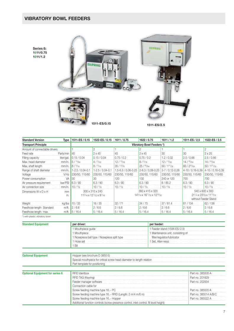
Standard Version Type 1511-ES / 0.15 1522-ES / 0.15 1611 / 0.75 1622 / 0.75 1611 / 1.2 1511-ES / 2.5 1522-ES / 2.5
Transport Principle Vibratory Bowl Feeders *)Amount of connectable drivers 1 2 1 2 1 1 2Feed rate Parts/min 45 2 x 45 45 2 x 45 30 30 2 x 25Filling capacity liter/gal. 0.15 / 0.04 0.15 / 0.04 0.75 / 0.2 0.75 / 0.2 1.2 / 0.32 2.5 / 0.66 2.5 / 0.66Max. head diameter mm/in. 5 / 13/64 4 / 5/32 12 / 15/32 8 / 5/16 12 / 15/32 14 / 35/64 14 / 35/64
Max. shaft length mm/in. 8 / 5/16 8 / 5/16 35 / 13/8 25 / 63/64 50 / 131/32 60 / 223/64 50 / 131/32
Range of shaft diameter mm/in. 1-2.5 / 0.04-0.1 1-2.5 / 0.04-0.1 1.5-6.3 / 0.06-0.25 2-6.3 / 0.08-0.25 3-7 / 0.12-0.28 4-10 / 0.16-0.39 4-10 / 0.16-0.39Voltage V/Hz 230/50, 115/60 230/50, 115/60 230/50, 115/60 230/50, 115/60 230/50, 115/60 230/50, 115/60 230/50, 115/60Power consumption VA 30 30 120 130 240 or 120 700 700Air pressure requirement bar/PSI 6.3 / 90 6.3 / 90 6.3 / 90 6.3 / 90 6 / 85.2 6.3 / 90 6.3 / 90Air connection size mm/in. 10 / 3/8 10 / 3/8 10 / 3/8 10 / 3/8 10 / 3/8 10 / 3/8 10 / 3/8
Dimensions W x D x H mm in.
300 x 310 x 240113/16 x 127/32 x 97/16
360 x 415 x 320143/16 x 1611/32 x 1219/32
540 x 600 x 300 211/4 x 235/8 x 1113/16
without Feeder StandWeight kg/lbs 15 / 33 16 / 35 32 / 71 34 / 75 37 / 81.4 61 / 134 62 / 136Feedhose length Standard m/ft. 2 / 6.6 2 / 6.6 2 / 6.6 2 / 6.6 2 / 6.6 2 / 6.6 2 / 6.6Feedhose length max. m/ft. 5 / 16.4 5 / 16.4 5 / 16.4 5 / 16.4 5 / 16.4 5 / 16.4 5 / 16.4*) with plastic vibratory bowl
1511-ES/2.51511-ES/0.15
Standard Equipment per driver: per feeder:
1 Mouthpiece guide 1 Feeder stand (15XX-ES/2.5)1 Mouthpiece 1 Maintenance unit, consisting of1 Nosepiece ball type / Nosepiece split type filter/regulator/lubricator1 Hose set 1 Set, Allen-keys1 Bit
Optional Equipment for series 6 RFID Identbox Part no. 385505 ARFID TAG (Keyring) Part no. 201829Feeder manager software Part no. 202934Connection cable forScrew feeding machine type 16..- PC Part no. 385520 AScrew feeding machine type 16..- RFID (Length: 2 m/4 m/6 m) Part no. 385514 A/B/CScrew feeding machine type 16..- Hopper Part no. 385522 AAdditional function controls (screw presence control, inlet control, fill level height)
Optional Equipment Hopper (see brochure D 3850 E)Special mouthpiece for critical screw head diameter to length relationPart template for positioning
Series 6:1611/0.751611/1.2
VIBRATORY BOWL FEEDERS
8
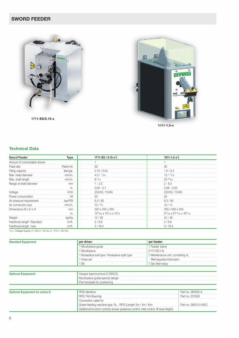
Sword Feeder Type 1711-ES / 0.15-x*) 1811-1.5-x*)
Amount of connectable drivers 1 1Feed rate Parts/min 30 30Filling capacity liter/gal. 0.15 / 0.04 1.5 / 0.4Max. head diameter mm/in. 4.5 / 11/64 12 / 15/32
Max. shaft length mm/in. 8 5/16 25 63/64
Range of shaft diameter mm 1 - 2.5 2 - 6.3 in. 0.04 - 0.1 0.08 - 0.25Voltage V/Hz 230/50, 115/60 230/50, 115/60Power consumption VA 20 20Air pressure requirement bar/PSI 6.3 / 90 6.3 / 90Air connection size mm/in. 10 / 3/8 10 / 3/8Dimensions W x D x H mm 320 x 255 x 260 250 x 550 x 500 in. 1219/32 x 101/32 x 101/4 927/32 x 2121/32 x 1911/16
Weight kg/lbs 12 / 26 22 / 48Feedhose length Standard m/ft. 2 / 6.6 2 / 6.6Feedhose length max. m/ft. 5 / 16.4 5 / 16.4
Technical Data
1711-ES/0.15-x
1811-1.5-x
*) x = Voltage Supply (1: 230 V / 50 Hz, 2: 115 V / 60 Hz)
Standard Equipment: per driver: per feeder:
1 Mouthpiece guide 1 Feeder stand 1 Mouthpiece (1711-ES/1.5)1 Nosepiece ball type / Nosepiece split type 1 Maintenance unit, consisting of,1 Hose set filter/regulator/lubricator1 Bit 1 Set Allen-keys
Optional Equipment for series 8: RFID Identbox Part no. 385505 ARFID TAG (Keyring) Part no. 201829Connection cable forScrew feeding machine type 18..- RFID (Length 2m / 4m / 6m) Part no. 385514 A/B/CAdditional function controls (screw presence control, inlet control, fill level height)
Optional Equipment: Hopper (see brochure D 3850 E)Mouthpiece guide special designPart template for positioning
SWORD FEEDER
9
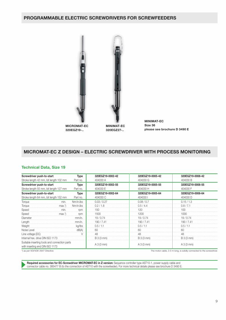
Screwdriver push-to-start TypeStroke length 42 mm, bit length 102 mm Part no.
320EGZ19-0002-42404030 A
320EGZ19-0005-42404030 G
320EGZ19-0008-42404030 B
Screwdriver push-to-start TypeStroke length 55 mm, bit length 127 mm Part no.
320EGZ19-0002-55404030 E
320EGZ19-0005-55404030 H
320EGZ19-0008-55404030 F
Screwdriver push-to-start TypeStroke length 64 mm, bit length 152 mm Part no.
320EGZ19-0002-64404030 C
320EGZ19-0005-64404030 I
320EGZ19-0008-64404030 D
Torque min. Nm/in.lbs 0.03 / 0.27 0.08 / 0.7 0.15 / 1.3Torque max.*) Nm/in.lbs 0.2 / 1.8 0.5 / 4.4 0.8 / 7.1Speed min. rpm 150 120 100Speed max.*) rpm 1500 1200 1000Diameter mm/in. 19 / 0.74 19 / 0.74 19 / 0.74Length mm/in. 190 / 7.41 190 / 7.41 190 / 7.41Weight kg/lbs 0.5 / 1.1 0.5 / 1.1 0.5 / 1.1Noise Level dB(A) 60 60 60Line voltage (DC) V 48 48 48Internal hex. drive DIN ISO 1173 B 3 (3 mm) B 3 (3 mm) B 3 (3 mm)Suitable inserting tools and connection partswith inserting end DIN ISO 1173
A 3 (3 mm) A 3 (3 mm) A 3 (3 mm)
MICROMAT-EC320EGZ19-..
MINIMAT-EC320EGZ27-..
MINIMAT-ECSize 36please see brochure D 3490 E
The motor cable, 2.5 m long, is solidly connected to the screwdriver.
Required accessories for EC-Screwdriver MICROMAT-EC in Z version: Sequence controller type AST10-1, power supply cable andconnector cable no. 385477 B (to the connection of AST10 with the screwfeeder). For more technical details please see brochure D 3490 E.
*) as per VDI/VDE 2647 Directive
Technical Data, Size 19
PROGRAMMABLE ELECTRIC SCREWDRIVERS FOR SCREWFEEDERS
MICROMAT-EC Z DESIGN – ELECTRIC SCREWDRIVER WITH PROCESS MONITORING
10
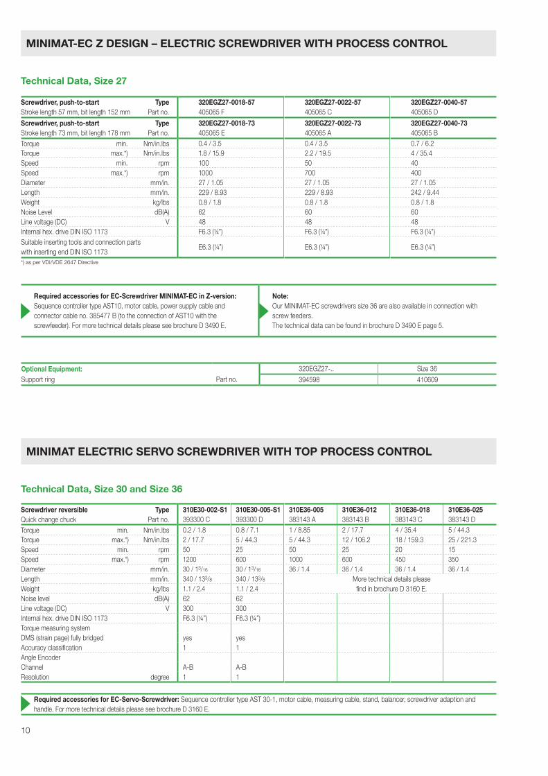
Screwdriver, push-to-start TypeStroke length 57 mm, bit length 152 mm Part no.
320EGZ27-0018-57405065 F
320EGZ27-0022-57405065 C
320EGZ27-0040-57405065 D
Screwdriver, push-to-start TypeStroke length 73 mm, bit length 178 mm Part no.
320EGZ27-0018-73405065 E
320EGZ27-0022-73405065 A
320EGZ27-0040-73405065 B
Torque min. Nm/in.lbs 0.4 / 3.5 0.4 / 3.5 0.7 / 6.2Torque max.*) Nm/in.lbs 1.8 / 15.9 2.2 / 19.5 4 / 35.4Speed min. rpm 100 50 40Speed max.*) rpm 1000 700 400Diameter mm/in. 27 / 1.05 27 / 1.05 27 / 1.05Length mm/in. 229 / 8.93 229 / 8.93 242 / 9.44Weight kg/lbs 0.8 / 1.8 0.8 / 1.8 0.8 / 1.8Noise Level dB(A) 62 60 60Line voltage (DC) V 48 48 48Internal hex. drive DIN ISO 1173 F6.3 (1/4”) F6.3 (1/4”) F6.3 (1/4”)Suitable inserting tools and connection partswith inserting end DIN ISO 1173
E6.3 (1/4”) E6.3 (1/4”) E6.3 (1/4”)
Screwdriver reversible TypeQuick change chuck Part no.
310E30-002-S1393300 C
310E30-005-S1393300 D
310E36-005383143 A
310E36-012383143 B
310E36-018383143 C
310E36-025383143 D
Torque min. Nm/in.lbs 0.2 / 1.8 0.8 / 7.1 1 / 8.85 2 / 17.7 4 / 35.4 5 / 44.3Torque max.*) Nm/in.lbs 2 / 17.7 5 / 44.3 5 / 44.3 12 / 106.2 18 / 159.3 25 / 221.3Speed min. rpm 50 25 50 25 20 15Speed max.*) rpm 1200 600 1000 600 450 350Diameter mm/in. 30 / 13/16 30 / 13/16 36 / 1.4 36 / 1.4 36 / 1.4 36 / 1.4Length mm/in. 340 / 133/8 340 / 133/8 More technical details pleaseWeight kg/lbs 1.1 / 2.4 1.1 / 2.4 find in brochure D 3160 E.Noise level dB(A) 62 62Line voltage (DC) V 300 300Internal hex. drive DIN ISO 1173 F6.3 (1/4”) F6.3 (1/4”)Torque measuring systemDMS (strain page) fully bridged yes yesAccuracy classification 1 1Angle EncoderChannel A-B A-BResolution degree 1 1
Notwendiges Zubehör für EC-Servo-Schrauber: Ablaufsteuerung AST30-1, Motorkabel, Messkabel, Stativ, Gewichtsausgleicher, Schrauber-aufnahme und Handgriff sowie weitere technische Einzelheiten hierzu siehe Druckschrift D 3160.
Technical Data, Size 27
MINIMAT-EC Z DESIGN – ELECTRIC SCREWDRIVER WITH PROCESS CONTROL
*) as per VDI/VDE 2647 Directive
Technical Data, Size 30 and Size 36
MINIMAT ELECTRIC SERVO SCREWDRIVER WITH TOP PROCESS CONTROL
Required accessories for EC-Screwdriver MINIMAT-EC in Z-version: Sequence controller type AST10, motor cable, power supply cable andconnector cable no. 385477 B (to the connection of AST10 with thescrewfeeder). For more technical details please see brochure D 3490 E.
Note: Our MINIMAT-EC screwdrivers size 36 are also available in connection with screw feeders.The technical data can be found in brochure D 3490 E page 5.
Required accessories for EC-Servo-Screwdriver: Sequence controller type AST 30-1, motor cable, measuring cable, stand, balancer, screwdriver adaption and handle. For more technical details please see brochure D 3160 E.
Optional Equipment: 320EGZ27-.. Size 36Support ring Part no. 394598 410609
11
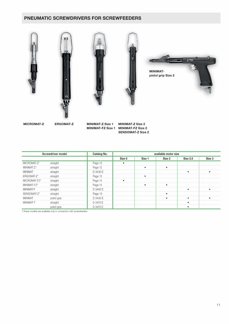
Screwdriver model Catalog No. available motor size
Size 0 Size 1 Size 2 Size 2.5 Size 3MICROMAT-Z* straight Page 12 •MINIMAT-Z* straight Page 12 • •
MINIMAT straight D 3430 E • •ERGOMAT-Z* straight Page 13 •MICROMAT-FZ* straight Page 14 •MINIMAT-FZ* straight Page 14 • •
MINIMAT-F straight D 3440 E • •SENSOMAT-Z* straight Page 15 •MINIMAT pistol grip D 3435 E • • •MINIMAT-T straight D 3470 E •
pistol grip D 3470 E •*) these models are available only in connection with screwfeeders
MICROMAT-Z ERGOMAT-Z MINIMAT-Z Size 1MINIMAT-FZ Size 1
MINIMAT-Z Size 2MINIMAT-FZ Size 2SENSOMAT-Z Size 2
MINIMAT-pistol grip Size 2
PNEUMATIC SCREWDRIVERS FOR SCREWFEEDERS
12
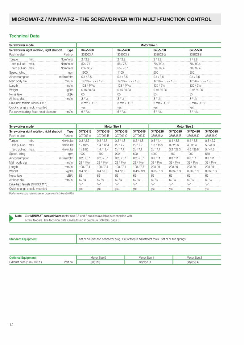
Screwdriver model Motor Size 0
Screwdriver right rotation, right shut-off TypePush-to-start Part no.
345Z-308338053 A
345Z-408338053 E
345Z-708338053 G
345Z-508338053 B
Torque min. Ncm/in.oz 2 / 2.8 2 / 2.8 2 / 2.8 2 / 2.8 soft pull-up max. Ncm/in.oz 50 / 71 55 / 78.1 70 / 99.4 70 / 99.4 hard pull-up max. Ncm/in.oz 60 / 85.2 55 / 78.1 70 / 99.4 70 / 99.4Speed, idling rpm 1600 1100 600 350Air consumption m3/min/cfm 0.1 / 3.5 0.1 / 3.5 0.1 / 3.5 0.1 / 3.5Main body dia. mm/in. 17/26 – 11/16 / 11/32 17/26 – 11/16 / 11/32 17/26 – 11/16 / 11/32 17/26 – 11/16 / 11/32
Length mm/in. 123 / 427/32 123 / 427/32 130 / 51/8 130 / 51/8
Weight kg/lbs 0.15 / 0.33 0.15 / 0.33 0.16 / 0.35 0.16 / 0.35Noise level dB(A) 65 65 65 65Air hose dia. mm/in. 3 / 1/8 3 / 1/8 3 / 1/8 3 / 1/8
Drive hex. female DIN ISO 1173 3 mm / .118” 3 mm / .118” 3 mm / .118” 3 mm / .118”Quick change chuck, mounted yes yes yes yesFor screwfeeding: Max. head diameter mm/in. 6 / 15/64 6 / 15/64 6 / 15/64 6 / 15/64
Screwdriver model Motor Size 1 Motor Size 2
Screwdriver right rotation, right shut-off TypePush-to-start Part no.
347Z-218397063 A
347Z-318397063 B
347Z-518397063 C
347Z-618397063 D
347Z-228389638 A
347Z-328389638 B
347Z-428389638 D
347Z-528389638 C
Torque min. Nm/in.lbs 0.3 / 2.7 0.3 / 2.7 0.2 / 1.8 0.2 / 1.8 0.5 / 4.4 0.4 / 3.5 0.4 / 3.5 0.3 / 2.7 soft pull-up max. Nm/in.lbs 1 / 8.85 1.4 / 12.4 2 / 17.7 2 / 17.7 1.8 / 15.9 3 / 26.6 4 / 35.4 5 / 44.3 hard pull-up max. Nm/in.lbs 1 / 8.85 1.4 / 12.4 2 / 17.7 2 / 17.7 2 / 17.7 3.2 / 28.3 4.5 / 39.8 5 / 44.3Speed, idling rpm 1900 1300 900 600 4000 1550 1000 680Air consumption m3/min/cfm 0.23 / 8.1 0.23 / 8.1 0.23 / 8.1 0.23 / 8.1 0.3 / 11 0.3 / 11 0.3 / 11 0.3 / 11Main body dia. mm/in. 28 / 17/64 28 / 17/64 28 / 17/64 28 / 17/64 33 / 15/16 33 / 15/16 33 / 15/16 33 / 15/16
Length mm/in. 190 / 7.4 190 / 7.4 190 / 7.4 198 / 7.7 228 / 9 228 / 9 228 / 9 228 / 9Weight kg/lbs 0.4 / 0.8 0.4 / 0.8 0.4 / 0.8 0.43 / 0.9 0.85 / 1.9 0.86 / 1.9 0.86 / 1.9 0.86 / 1.9Noise level dB(A) 62 62 62 62 62 62 62 62Air hose dia. mm/in. 6 / 1/4 6 / 1/4 6 / 1/4 6 / 1/4 6 / 1/4 6 / 1/4 6 / 1/4 6 / 1/4
Drive hex. female DIN ISO 1173 1/4” 1/4” 1/4” 1/4” 1/4” 1/4” 1/4” 1/4”Quick change chuck, mounted yes yes yes yes yes yes yes yesPerformance data relate to an air pressure of 6.3 bar (90 PSI)
Optional Equipment: Motor Size 0 Motor Size 1 Motor Size 2Exhaust hose (1 m / 3.3 ft.) Part no. 806113 402957 B 389653 A
Standard Equipment: Set of coupler and connector plug · Set of torque adjustment tools · Set of clutch springs
Note: Our MINIMAT screwdrivers motor size 2.5 and 3 are also available in connection with screw feeders. The technical data can be found in brochure D 3430 E page 3.
MICROMAT-Z / MINIMAT-Z – THE SCREWDRIVER WITH MULTI-FUNCTION CONTROL
Technical Data
13
Screwdriver model Motor Size 1Screwdriver right rotation, right shut-off TypePush-to-start Part no.
347V-218406859 A
347V-318406859 B
347V-518406859 C
347V-718406859 G
Torque min. Nm/in.lbs 0.3 / 2.7 0.3 / 2.7 0.2 / 1.8 0.2 / 1.8Torque max. Nm/in.lbs 1 / 8.85 1.4 / 12.4 2 / 17.7 2.5 / 22.1Speed, idling rpm 1900 1300 900 640Air consumption m3/min/cfm 0.23 / 8 0.23 / 8 0.23 / 8 0.23 / 8Main body dia. mm/in. 32/38 – 11/4 / 11/2 32/38 – 11/4 / 11/2 32/38 – 11/4 / 11/2 32/38 – 11/4 / 11/2
Length mm/in. 250 / 927/32 250 / 927/32 250 / 927/32 250 / 927/32
Weight kg/lbs 0.8 / 1.8 0.8 / 1.8 0.8 / 1.8 0.8 / 1.8Noise level dB(A) 63 63 63 66Air hose dia. mm/in. 6 / 1/4 6 / 1/4 6 / 1/4 6 / 1/4
Drive hex. female DIN ISO 1173 1/4” 1/4” 1/4” 1/4”Quick change chuck, mounted yes yes yes yesFor screwfeeding: Max. head diameter mm/in. 8 / 5/16 8 / 5/16 8 / 5/16 8 / 5/16
Performance data relate to an air pressure of 6.3 bar (90 PSI)
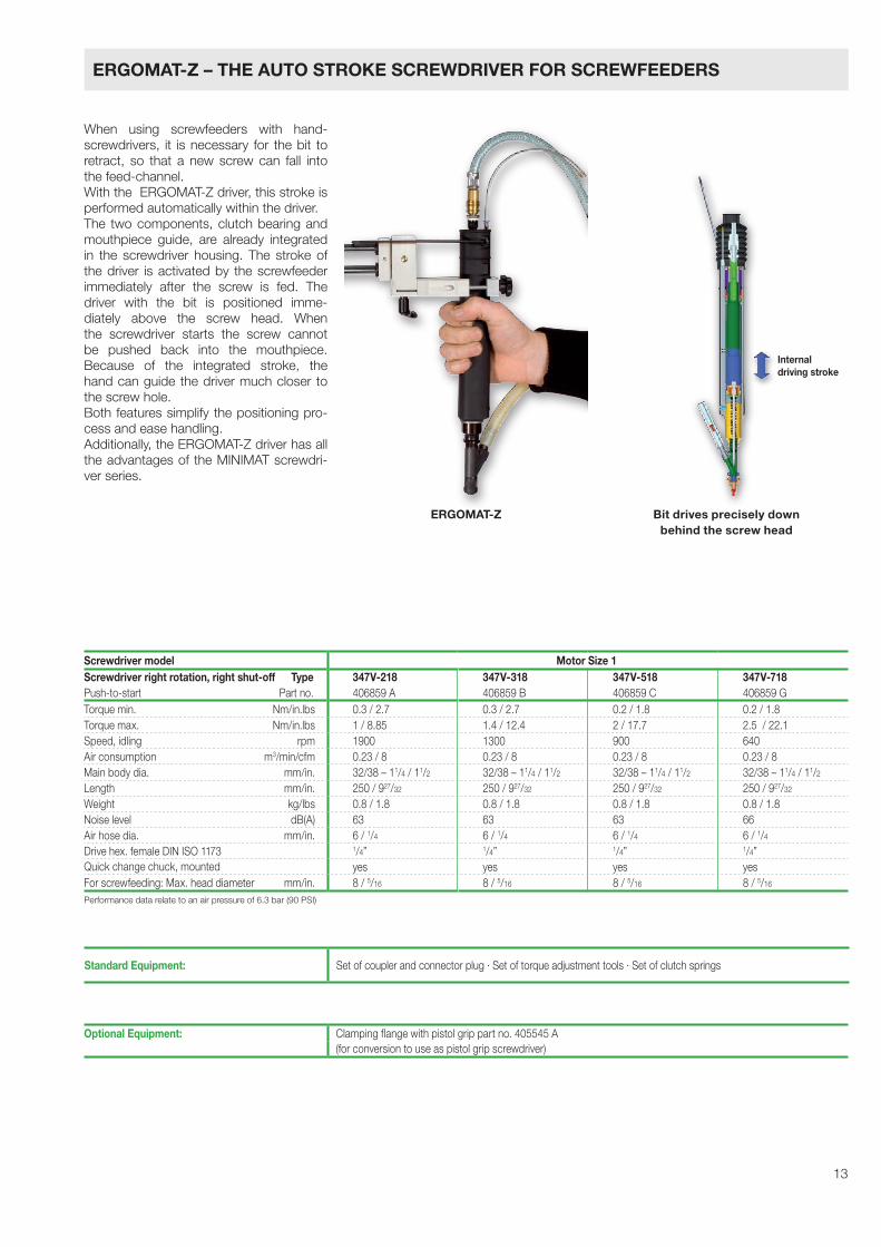
When using screwfeeders with hand- screwdrivers, it is necessary for the bit to retract, so that a new screw can fall into the feed-channel. With the ERGOMAT-Z driver, this stroke is per formed automatically within the driver.The two components, clutch bearing and mouthpiece guide, are already integrated in the screwdriver housing. The stroke of the driver is activated by the screwfeeder immediately after the screw is fed. The driver with the bit is positioned imme-diately above the screw head. When the screwdriver starts the screw cannot be pushed back into the mouthpiece.Because of the integrated stroke, the hand can guide the driver much closer to the screw hole. Both features simplify the positioning pro-cess and ease handling. Additionally, the ERGOMAT-Z driver has all the advantages of the MINIMAT screwdri-ver series.
ERGOMAT-Z Bit drives precisely downbehind the screw head
Optional Equipment: Clamping flange with pistol grip part no. 405545 A(for conversion to use as pistol grip screwdriver)
Standard Equipment: Set of coupler and connector plug · Set of torque adjustment tools · Set of clutch springs
Internaldriving stroke
ERGOMAT-Z – THE AUTO STROKE SCREWDRIVER FOR SCREWFEEDERS
14
Screwdriver model Motor Size 1 Motor Size 2
Screwdriver right rotation, right shut-off TypePush-to-start Part no.
347FZ-218397064 A
347FZ-318397064 B
347FZ-518397064 C
347FZ-618397064 D
347FZ-228390846 A
347FZ-328390846 B
347FZ-428390846 D
347FZ-528390846 C
Torque min. Nm/in.lbs 0.3 / 2.7 0.3 / 2.7 0.2 / 1.8 0.2 / 1.8 0.5 / 4.4 0.4 / 3.5 0.4 / 3.5 0.3 / 2.7 soft pull-up max. Nm/in.lbs 1 / 8.85 1.4 / 12.4 2 / 17.7 2 / 17.7 1.8 / 15.9 3 / 26.6 4 / 35.4 5 / 44.3 hard pull-up max. Nm/in.lbs 1 / 8.85 1.4 / 12.4 2 / 17.7 2 / 17.7 2 / 17.7 3.2 / 28.3 4.5 / 39.8 5 / 44.3Speed, idling rpm 1900 1300 900 600 4000 1550 1000 680Air consumption m3/min/cfm 0.23 / 8.1 0.23 / 8.1 0.23 / 8.1 0.23 / 8.1 0.3 / 11 0.3 / 11 0.3 / 11 0.3 / 11Main body dia. mm/in. 28 / 17/64 28 / 17/64 28 / 17/64 28 / 17/64 33 / 15/16 33 / 15/16 33 / 15/16 33 / 15/16
Length mm/in. 190 / 7.4 190 / 7.4 190 / 7.4 198 / 7.7 228 / 9 228 / 9 228 / 9 228 / 9Weight kg/lbs 0.4 / 0.8 0.4 / 0.8 0.4 / 0.8 0.43 / 0.9 0.85 / 1.9 0.86 / 1.9 0.86 / 1.9 0.86 / 1.9Noise level dB(A) 62 62 62 62 69 69 69 69Air hose dia. mm/in. 6 / 1/4 6 / 1/4 6 / 1/4 6 / 1/4 6 / 1/4 6 / 1/4 6 / 1/4 6 / 1/4Drive hex. female DIN ISO 1173 1/4” 1/4” 1/4” 1/4” 1/4” 1/4” 1/4” 1/4”Quick change chuck, mounted yes yes yes yes yes yes yes yes
Screwdriver model Motor Size 0
Screwdriver right rotation, right shut-off TypePush-to-start Part no.
345FZ-308399445 A
345FZ-408399445 B
345FZ-708399445 C
345FZ-508399445 D
Torque min. Nm/in.lbs 0.02 / 0.18 0.02 / 0.18 0.02 / 0.18 0.02 / 0.18 soft pull-up max. Nm/in.lbs 0.5 / 4.4 0.55 / 4.9 0.7 / 6.2 0.7 / 6.2 hard pull-up max. Nm/in.lbs 0.6 / 5.3 0.55 / 4.9 0.7 / 6.2 0.7 / 6.2Speed, idling rpm 1600 1100 600 350Air consumption m3/min/cfm 0.1 / 3.5 0.1 / 3.5 0.1 / 3.5 0.1 / 3.5Main body dia. mm/in. 17 / 11/16 17 / 11/16 17 / 11/16 17 / 11/16
Length mm/in. 152 / 6 152 / 6 158 / 67/32 158 / 67/32
Weight kg/lbs 0.15 / 0.33 0.15 / 0.33 0.16 / 0.35 0.16 / 0.35Noise level dB(A) 65 65 65 65Air hose dia. mm/in. 3 / 1/8 3 / 1/8 3 / 1/8 3 / 1/8
Drive hex. female DIN ISO 1173 3 mm / .118” 3 mm / .118” 3 mm / .118” 3 mm / .118”Quick change chuck, mounted yes yes yes yes
Performance data relate to an air pressure of 6.3 bar (90 PSI) incl. 2 m/6.56 ft. air supply hose (lengths up to 5 m/16.4 ft. available)
Required accessories for MICROMAT-/MINIMAT-FZ screwdri-vers: Controller fc11/fc 20 and pc11/pc20, as well as connection set no. 3568501C/D/E (to the connection of controller fc.. with the screw-feeder). For more technical details please see brochure D 3440 E.
Note: Our MINIMAT-F screwdrivers motor size 2.5 and 3 straightversion are also available in connection with screw feeders.The technical data can be found in brochure D 3440 E page 2.
Standard Equipment: Set of coupler and connector plug · Set of torque adjustment tools · Set of clutch springs
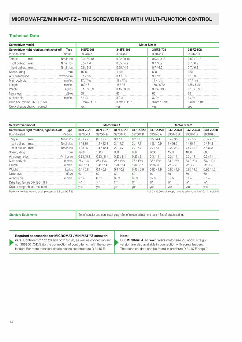
MICROMAT-FZ/MINIMAT-FZ – THE SCREWDRIVER WITH MULTI-FUNCTION CONTROL
Technical Data
15
Performance data relate to an air pressure of 6.3 bar (90 PSI)
Screwdriver model Motor Size 2
Screwdriver right rotation, right shut-off TypePush-to-start Part no.
347SZ-328391130 B
347SZ-428391130 C
347SZ-528391130 D
Seating torque, minimum Nm/in.lbs 0.4 / 3.5 0.4 / 3.5 0.3 / 2.7Seating torque, maximum Nm/in.lbs 3 / 26.6 4 / 35.4 5 / 44.3Driving torque, maximum Nm/in.lbs 3.3 / 29.2 4.4 / 38.9 5.5 / 48.7Speed, idling rpm 1550 1000 680Air consumption m3/min/cfm 0.3 / 11 0.3 / 11 0.3 / 11Main body dia. mm/in. 33 / 15/16 33 / 15/16 33 / 15/16
Length mm/in. 228 / 9 228 / 9 228 / 9Weight kg/lbs 0.86 / 1.9 0.86 / 1.9 0.86 / 1.9Noise level dB(A) 62 62 62Air hose dia. mm/in. 6 / 1/4 6 / 1/4 6 / 1/4Drive hex. female DIN ISO 1173 1/4” 1/4” 1/4”Quick change chuck, mounted yes yes yes
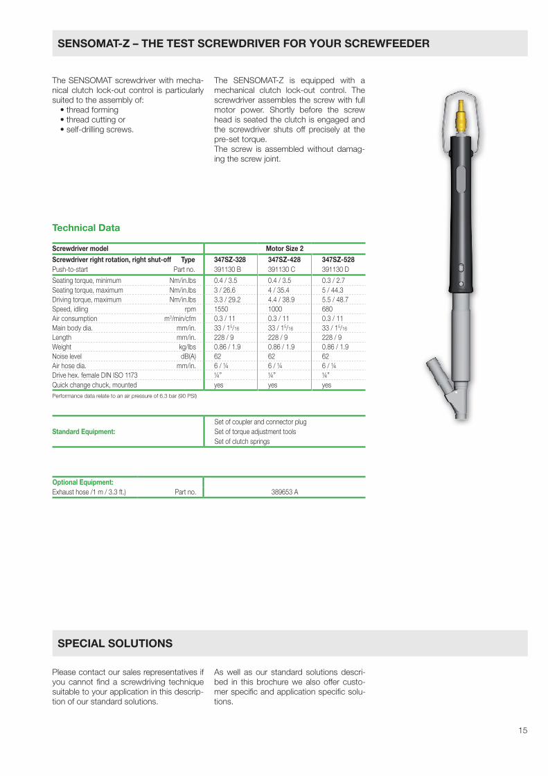
The SENSOMAT screwdriver with mecha-nical clutch lock-out control is particularly suited to the assembly of:•threadforming•threadcuttingor•self-drillingscrews.
The SENSOMAT-Z is equipped with a mechanical clutch lock-out control. The screwdriver assembles the screw with full motor power. Shortly before the screw head is seated the clutch is engaged and the screwdriver shuts off precisely at the pre-set torque.The screw is assembled without damag- ing the screw joint.
Please contact our sales representatives if you cannot find a screwdriving technique suitable to your application in this descrip-tion of our standard solutions.
As well as our standard solutions descri-bed in this brochure we also offer custo-mer specific and application specific solu-tions.
Technical Data
Standard Equipment: Set of coupler and connector plug Set of torque adjustment tools Set of clutch springs
Optional Equipment:Exhaust hose /1 m / 3.3 ft.) Part no. 389653 A
SENSOMAT-Z – THE TEST SCREWDRIVER FOR YOUR SCREWFEEDER
SPECIAL SOLUTIONS

DEPRAG SCHULZ GMBH u. CO. P.O. Box 1352, D-92203 Amberg, GermanyCarl-Schulz-Platz 1, D-92224 AmbergPhone (+49) 9621 371-0, Fax (+49) 9621 [email protected]
Tech
nica
l alte
ratio
ns re
serv
ed
– F
ri
C E R T I F I E D A S P E R D I N E N I S O 9 0 0 1