
SCP 20 - SC 11 13 00 00 SP - Installation of Equipment ...
49
Discipline Engineering Standard – NSW Category Signalling Title Installation of Equipment Racks and Termination of Cables and Wiring Reference Number SCP 20 – (RIC Standard: SC 11 13 00 00 SP) Document Control Status Date Prepared Reviewed Endorsed Approved Standards and Systems Standards Engineer GM Infrastructure Strategy & Performance Safety Committee Issue 1 Revision 2 Mar 05 Refer to Reference Number H Olsen M Owens Refer to minutes of meeting 12/08/04
Transcript of SCP 20 - SC 11 13 00 00 SP - Installation of Equipment ...
DisciplineEngineering Standard –NSW
CategorySignalling
Title
Installation of Equipment Racks andTermination of Cables and Wiring
Reference Number
SCP 20 –(RIC Standard: SC 11 13 00 00 SP)
Document Control
Status Date Prepared Reviewed Endorsed Approved
Standards andSystems
StandardsEngineer
GMInfrastructure
Strategy &Performance
SafetyCommittee
Issue 1Revision 2
Mar 05
Refer toReferenceNumber
H Olsen M OwensRefer to minutes
of meeting12/08/04

Engineering Standard–NSWSignalling SCP 20Installation of Equipment Racks and Termination of Cables and Wiring
Issue 1 © Australian Rail Track CorporationRevision 2 This document is uncontrolled when printedMarch 2005 Page 2 of 49
DISCLAIMER
Australian Rail Track Corporation has used its best endeavors to ensure that thecontent, layout and text of this document is accurate, complete and suitable for itsstated purpose. It makes no warranties, express or implied, that compliance withthe contents of this document shall be sufficient to ensure safe systems of work oroperation. Australian Rail Track Corporation will not be liable to pay compensationin respect of the content or subsequent use of this document for any other purposethan its stated purpose or for any purpose other than that for which it wasprepared except where it can be shown to have acted in bad faith or there hasbeen willful default.
DOCUMENT APPROVAL
The technical content of this document has been approved by the relevant ARTCengineering authority and has also been endorsed by the ARTC SafetyCommittee.
DOCUMENT SUPPLY and CONTROL
The Primary Version of this document is the electronic version that is available andaccessible on the Australian Rail Track Corporation Internet and Intranet website.
It is the document user’s sole responsibility to ensure that copies are checked for currency against the Primary Version prior to its use.
COPYRIGHT
The information in this document is Copyright protected. Apart from thereproduction without alteration of this document for personal use, non-profitpurposes or for any fair dealing as permitted under the Copyright Act 1968, no partof this document may be reproduced, altered, stored or transmitted by any personwithout the prior written consent of ARTC.
Engineering Standard–NSWSignalling SCP 20Installation of Equipment Racks and Termination of Cables and Wiring
Issue 1 © Australian Rail Track CorporationRevision 2 This document is uncontrolled when printedMarch 2005 Page 3 of 49
About This StandardThis Standard Specification sets out the requirements for cable jointing,terminating and wiring of signalling systems and installation of equipment racksand cubicles. It shall be read in conjunction with the other standardspecifications referenced within this document.

Engineering Standard–NSWSignalling SCP 20Installation of Equipment Racks and Termination of Cables and Wiring
Issue 1 © Australian Rail Track CorporationRevision 2 This document is uncontrolled when printedMarch 2005 Page 4 of 49
Document HistoryPrimary Source –RIC Standard SC 11 13 00 00 SP Version 3.0
List of Amendments –
ISSUE DATE CLAUSE DESCRIPTION1.1 01/09/2004 Reformatting to ARTC Standard1.2 14/03/2005 Disclaimer Minor editorial change
Footer reformatted
Engineering Standard–NSWSignalling SCP 20Installation of Equipment Racks and Termination of Cables and Wiring
Issue 1 © Australian Rail Track CorporationRevision 2 This document is uncontrolled when printedMarch 2005 Page 5 of 49
Contents
1. General ..................................................................................................................8
1.1. Scope ............................................................................................................................................8
1.2. Referenced Documents ..............................................................................................................8
1.3. Definitions ....................................................................................................................................9
1.4. Quality ........................................................................................................................................10
1.5. Painting/Finish of Metal Surfaces ............................................................................................10
1.6. Alternative Materials, Products or Processes ........................................................................10
2. Installation Of Equipment In Buildings ............................................................12
2.1. General .......................................................................................................................................12
2.2. Equipment Racks And Cubicles ..............................................................................................122.2.1. Equipment Racks ...............................................................................................................122.2.2. Equipment Mounting ..........................................................................................................12
3. Termination ........................................................................................................14
3.1. General .......................................................................................................................................14
3.2. Fuse Holders and Terminal Blocks .........................................................................................14
3.3. Plug Connectors ........................................................................................................................14
3.4. Spacing of Terminals ................................................................................................................143.4.1. DIN Rail Mounted Terminals ..............................................................................................143.4.2. Stud Type Terminals ..........................................................................................................15
3.5. Crimp Lugs and Ferrules ..........................................................................................................15
3.6. Fuse Holders ..............................................................................................................................15
3.7. Terminal Blocks .........................................................................................................................15
3.8. Plug Coupling ............................................................................................................................16
3.9. Cable Crimps and Crimp Tool Details .....................................................................................16
3.10. Heat Shrink Sleeves .............................................................................................................17
4. Termination and Wiring Of Equipment .............................................................18
4.1. Termination of Signalling Cables in Relay Rooms and Location Cases .............................18
4.2. Wiring Of Trackside Equipment ...............................................................................................184.2.1. General ...............................................................................................................................184.2.2. Track Circuits ......................................................................................................................194.2.3. Traction Bonding ................................................................................................................20
Engineering Standard–NSWSignalling SCP 20Installation of Equipment Racks and Termination of Cables and Wiring
Issue 1 © Australian Rail Track CorporationRevision 2 This document is uncontrolled when printedMarch 2005 Page 6 of 49
4.2.4. Impedance Bonds ............................................................................................................. 204.2.5. Rail Bonds, V&K Crossing Bonds ..................................................................................... 204.2.6. Rail Connection for Spark Gap Arrestor Bond .................................................................. 214.2.7. Connections from Traction Negative Busbars to Rails ..................................................... 214.2.8. Tie-in Bonds Between Tracks ........................................................................................... 224.2.9. Electrolysis Bond Connections .......................................................................................... 224.2.10. Signals - Post and Gantry Mounted ................................................................................ 224.2.11. Trainstops ........................................................................................................................ 234.2.12. Point Machines ................................................................................................................ 234.2.13. Electro-pneumatic Points Mechanisms ........................................................................... 234.2.14. Releasing Switches and Ground Frame Operated Points .............................................. 244.2.15. Guards Indicators ............................................................................................................ 244.2.16. Traffic Huts ...................................................................................................................... 244.2.17. Emergency Switch Machine Lock (ESML), Emergency Operation Lock (EOL) ............ 244.2.18. Telephones ...................................................................................................................... 24
5. Wiring of Internal Equipment ............................................................................ 25
5.1. General ..................................................................................................................................... 25
5.2. Vital Wiring ............................................................................................................................... 25
5.3. Non-Vital Wiring ...................................................................................................................... 25
5.4. Wiring of Power Supplies ....................................................................................................... 25
6. Temporary Wiring And Stagework ................................................................... 26
7. Jointing Of Signalling Cables ........................................................................... 26
7.1. General ..................................................................................................................................... 26
7.2. Inspection ................................................................................................................................. 26
8. Jointing Communictions Cables ...................................................................... 27
8.1. General ..................................................................................................................................... 27
8.2. Jointing Requirements ........................................................................................................... 27
9. LABELLING ........................................................................................................ 29
9.1. General ..................................................................................................................................... 29
9.2. Wires and Cables to Fuses and Terminals ........................................................................... 29
9.3. Fuses, Terminals and Busbars .............................................................................................. 29
9.4. Plug-In Relays - Vital ............................................................................................................... 30
9.5. Circuit Breakers ....................................................................................................................... 30
9.6. Miscellaneous Internal Equipment ........................................................................................ 30
9.7. Trackside Equipment .............................................................................................................. 30
9.8. Temporary Work and Stagework ........................................................................................... 31
Engineering Standard–NSWSignalling SCP 20Installation of Equipment Racks and Termination of Cables and Wiring
Issue 1 © Australian Rail Track CorporationRevision 2 This document is uncontrolled when printedMarch 2005 Page 7 of 49
9.9. Partially Commissioned and De-Commissioned Work ........................................................ 31
10. Appendix A ........................................................................................................ 32
10.1. General ................................................................................................................................. 33
10.2. Feed Through Terminals ..................................................................................................... 33
10.3. Heavy Duty Feed Through .................................................................................................. 37
10.4. Test / Disconnect Terminals ............................................................................................... 39
10.5. Fuse Holders ........................................................................................................................ 39
10.6. Earthing Terminals .............................................................................................................. 41
11. Appendix B ........................................................................................................ 42
11.1. Procedure A ......................................................................................................................... 43
11.2. Procedure B ......................................................................................................................... 44
11.3. Procedure C ......................................................................................................................... 44
11.4. Procedure D ......................................................................................................................... 4511.4.1. Qualified Personnel .......................................................................................................... 4511.4.2. Safety ............................................................................................................................... 4511.4.3. Weld Preparation ............................................................................................................. 4511.4.4. Rail Preparation ................................................................................ 4611.4.5.Igniter ................................................................................................................................ 46
11.5. Welding Procedure .............................................................................................................. 46
11.6. Fixing Cables to Studs ........................................................................................................ 47
12. Appendix C ........................................................................................................ 48
12.1. General ................................................................................................................................. 49
12.2. Applicability ......................................................................................................................... 49
12.3. Materials required ................................................................................................................ 49
12.4. Description ........................................................................................................................... 49
Engineering Standard–NSWSignalling SCP 20Installation of Equipment Racks and Termination of Cables and Wiring
Issue 1 © Australian Rail Track CorporationRevision 2 This document is uncontrolled when printedMarch 2005 Page 8 of 49
1. General
1.1. Scope
This specification describes the requirement for:
Installation of equipment in buildings.
Installation of equipment racks and cubicles.
Types and Installation of Signalling fuse and terminal blocks.
Termination of signalling cables.
Wiring of trackside equipment
Wiring of internal equipment.
Wiring of power supplies.
Temporary wiring and stagework.
Labeling.
1.2. Referenced Documents
The following documents or publications are referenced within this specification:
Australian Standards
AS 2700 Colour Standards
AS 1394 Round Steel Wire for Ropes
AS 2373.1 Multi-core Control Cables
ARTC Specifications SCP 02 SPS 41 SPS 51 SPS 33 SPS 40 SCP 14 SPS 42

Engineering Standard–NSWSignalling SCP 20Installation of Equipment Racks and Termination of Cables and Wiring
Issue 1 © Australian Rail Track CorporationRevision 2 This document is uncontrolled when printedMarch 2005 Page 9 of 49
SPS 43 }
SPS 44 }
SPS 45 } Vital Signalling Cables
SPS 46 }
SPS 47 }
SPS 48 }
SPS 49 }
SCP 21 Cable Route Construction
SCP 04
Drawings
Lightning and SurgeProtection
D08301, E08616, E08179-3.
1.3. Definitions
Main Cables
Any cables which are run from a cable termination point in one building or location case, toa cable termination point in another building or location case.
Note that joints in cables including those for loading and balancing purposes do notconstitute a termination point of the cable for the purposes of defining Main and Localcables.
Local Cables
All other cables.
Internal Cables
Any cables which are wholly contained within a building or location case.
External Cables
Any cables which run outside a building or location case.
Hypalon
Synthetic rubber sheathing material, R-90-BP or equivalent
Engineering Standard–NSWSignalling SCP 20Installation of Equipment Racks and Termination of Cables and Wiring
Issue 1 © Australian Rail Track CorporationRevision 2 This document is uncontrolled when printedMarch 2005 Page 10 of 49
1.4. Quality
The standard of materials and workmanship shall ensure that the installed equipment, cabling andwiring is fit for purpose, over the lifetime of the asset in its physical and operational environment, interms of the standards of safety, reliability, durability, maintainability, operability andsupportability as set out in this Standard Specification and referenced documents.
Quality of materials and workmanship shall also ensure that the necessity for regular preventativemaintenance tasks to retain the safety, reliability and usability of the asset over its lifetime isminimised.
1.5. Painting/Finish of Metal Surfaces
Steel metalwork within relay rooms, buildings and location cases including relay racks, equipmentracks and housings, cabinets, plinths and bases shall be finished in light grey blue (No. B44) toAS2700 using a robust finish which will resist chipping and scratching and will provide corrosionprotection to the steelwork for a period of at least 25 years.
Bolts, nuts and other fastenings shall be provided with corrosion protection such as zinc platingand cable trays, if steel, shall be galvanised or provided with a finish which will provideequivalent life. Where part of a bolt or nut is external to a location case, the bolt or nut or bothshall be stainless steel.
Where steelwork is galvanised or provided with equivalent metallic protection no other surfacetreatment is necessary except where otherwise required by the particular specification.
Similarly, no additional surface protection is required for aluminium and stainless steel.
If powder coating, baked enamel or lacquered finishes are used, the metal shall be surfacecleaned, primed, undercoated and finished strictly in accordance with the paint manufacturer’srecommendations.
1.6. Alternative Materials, Products or Processes
Where this specification proposes a particular material, product or process or range of materials,products or processes, alternatives may be accepted for use where permitted by the ParticularSpecification, provided that they receive Type Approval and it can be demonstrated that thealternative:
Is fit for purpose.
Is better rather than worse in optimally achieving the performance requirements.
Improves rather than reduces system safety, security and availability.
Is closer rather than further from best practice.
Is equally or more suitable in form, fit and function, and equally or more compatible withit’s interfaces, operating environment and maintenance environment.

Engineering Standard–NSWSignalling SCP 20Installation of Equipment Racks and Termination of Cables and Wiring
Issue 1 © Australian Rail Track CorporationRevision 2 This document is uncontrolled when printedMarch 2005 Page 11 of 49
Increases rather than decreases compliance with environmental and occupational healthand safety requirements.
Decreases rather than increases life cycle costs.
Improves rather than reduces maintainability and supportability.
Increases rather than decreases adaptability for foreseeable changes.
Provides a net benefit to ARTC.
Acceptance of alternatives shall only entail acceptance of variations to the specification to theextent these are fully explained and explicitly detailed and documented.

Engineering Standard–NSWSignalling SCP 20Installation of Equipment Racks and Termination of Cables and Wiring
Issue 1 © Australian Rail Track CorporationRevision 2 This document is uncontrolled when printedMarch 2005 Page 12 of 49
2. Installation Of Equipment In Buildings
2.1. General
Racks and other equipment shall be located to make most effective use of the available floorspace and to provide unobstructed maintenance access.
Approximately 20% of the available space shall remain unused for the future installation ofadditional equipment, except where otherwise directed.
The minimum clearance between racks, cubicles, cupboards etc with all equipmentmounted shall be:
800mm between one end of a rack and any other fixed object. (One end may beagainst a wall or other rack if there is no need for access at that end)
900 mm at the rear of any rack which requires rear access.
900mm at the front of any rack.
1200mm between racks which require front and rear access.
750mm in front of any roll or slide out drawer or tray when extended.
The lowest point of any cable trays which pass over access ways or corridors between racks orother equipment shall be not less than 2.1 metres above floor level.
All equipment shall be mounted, fastened and braced, if necessary, to ensure that there is nopossibility of collapse or distortion under any normal operating condition including thepossibility of staff bumping into or falling against the equipment.
2.2. Equipment Racks And Cubicles
2.2.1. Equipment Racks
Except where otherwise specified or approved, the height of equipment racks and cubiclesshall not exceed 2 metres.
2.2.2. Equipment Mounting
No equipment shall be mounted less than 300mm from the floor. Wherever possibleequipment should not be mounted more than 1800mm above floor level.
Any sensitive equipment likely to be affected by vibration shall be housed on racks or incubicles mounted on vibration isolating footings or shall itself be mounted on vibrationisolators within the rack or cubicle.
Heat producing equipment shall be arranged so that rising heat shall not affect the operationof or damage any equipment mounted above or adjacent to it.
Engineering Standard–NSWSignalling SCP 20Installation of Equipment Racks and Termination of Cables and Wiring
Issue 1 © Australian Rail Track CorporationRevision 2 This document is uncontrolled when printedMarch 2005 Page 13 of 49
Enclosed racks or equipment cubicles shall be provided with access panels wherever necessaryto provide maintenance access to the equipment mounted therein and the cables or wiringterminated to that equipment.
All items of equipment shall be easily removable for maintenance or replacement withoutthe need to disconnect or remove other items or units of equipment on the rack or in thecubicle.
Where duplicate units of equipment are provided, such as dual power supplies, each unit ofthe duplicated equipment shall be packaged and mounted separately so that a defective unitcan be removed and replaced without affecting the operation of the serviceable unit.
Wiring shall also be arranged so that when a defective unit is being repaired or replaced it isnot necessary to disconnect or disturb the wiring to other equipment on the rack or in thecubicle.
Vital signalling equipment shall not be intermingled with non vital signalling equipment.However, both vital and non vital signalling equipment may be fitted to the one rack orwithin the one cubicle provided the vital signalling equipment is clearly separated from thenon vital signalling equipment.
Telecommunications equipment shall be mounted on separate racks from signallingequipment.

Engineering Standard–NSWSignalling SCP 20Installation of Equipment Racks and Termination of Cables and Wiring
Issue 1 © Australian Rail Track CorporationRevision 2 This document is uncontrolled when printedMarch 2005 Page 14 of 49
3. Termination
3.1. General
Soldering shall not be used as a means of terminating signalling conductors, vital or nonvital,except on the coil connections of large plug-in relays (e.g. Westinghouse VT1, BL1B, BT1B).
3.2. Fuse Holders and Terminal Blocks
Fuse holders and terminal blocks used within buildings and location cases shall be inaccordance with Specification SPS 51 and shall be DIN rail mounted screw clamp type (studfor some earthing and larger cables) or, in listed applications only, spring clamp type.
The maximum internal resistance connection to connection for any fuse holder or terminalblock shall be not more than 5 milliohms.
Wire wrap terminals for single strand conductors of appropriate sizes are acceptable only innon-vital applications.
Appendix A lists fuse holders and terminal blocks which have been Type Approved at thetime of writing of this specification. Other similar fuse and terminal blocks may beacceptable but will require Type Approval before use.
The limitations and applications listed in Appendix A shall be strictly adhered to.
3.3. Plug Connectors
Plug connectors shall comply with Specification SPS 06.
Plug connectors, both wire to wire and wire to circuit board edge, shall have gold plated(flashed) contacts and, where used for equipment located outside of buildings or wherevibration could be a factor, shall have a means of locking the plug and socket securelytogether.
3.4. Spacing of Terminals
3.4.1. DIN Rail Mounted Terminals
The surface tracking distance between the metal parts of adjacent terminal blocks shall be atleast 6.5 mm.
Rows of fuses and/or terminals shall be spaced at not less than 150mm centres except whereotherwise approved.

Engineering Standard–NSWSignalling SCP 20Installation of Equipment Racks and Termination of Cables and Wiring
Issue 1 © Australian Rail Track CorporationRevision 2 This document is uncontrolled when printedMarch 2005 Page 15 of 49
3.4.2. Stud Type Terminals
Stud type terminals shall have studs spaced at not less than 20mm centres unless aninsulating barrier at least 1/3 the height of the terminal stud is provided between adjacentpairs of terminals, in which case the spacing may be reduced to 16mm.
Stud type terminals shall be of a type in which the stud is captive in the current bar (or basewhere a separate link is used) or there is a captive nut into which the stud or bolt is screwed.Terminals in which a thread is tapped into the current bar for a free bolt are not acceptableunless the current bar thickness is at least 60% of the stud diameter.
Where pre-insulated crimp lugs are used on stud type terminals they shall be so arranged thatthey cannot touch or rest on other exposed terminals or on other lugs even if they becomeloose or be bent. Separate lock nuts shall be fitted to stud terminals except where self lockingnuts, such as Nyloc nuts, are used.
3.5. Crimp Lugs and Ferrules
Crimp lugs, crimp pins and bootlace ferrules shall comply with Specification SPS 33.
Application of lugs, pins and ferrules shall be in accordance with Specification SPS 33, usingthe appropriate approved manual ratchet or hydraulic crimp tools.
Wires with a single strand 1.5 mm diameter or more or multistrands (minimum 7 strands)each of 0.85 mm diameter or more may be terminated directly into screw clamp or springclamp terminal blocks or fuse holders without crimp lugs or ferrules.
3.6. Fuse Holders
Fuse holders and associated components which are Type Approved at the time of writing ofthis specification are listed in Appendix A. Other types of fuse holder may be considered butwill subject to Type Approval prior to use.
The limitations and applications listed in Appendix A shall be strictly adhered to.
3.7. Terminal Blocks
Incoming/outgoing vital cables in relay rooms and location cases shall be terminated onType Approved test/disconnect terminal blocks.
Cables and wires to neutral busbars shall be terminated on Type Approved test/disconnectterminal blocks.
Terminal blocks for inter rack wiring etc. shall be Type Approved "feed through" blocks ofappropriate size for the cable to be terminated.
BR930 series relay base terminations shall be as specified in British Rail specificationBR930.

Engineering Standard–NSWSignalling SCP 20Installation of Equipment Racks and Termination of Cables and Wiring
Issue 1 © Australian Rail Track CorporationRevision 2 This document is uncontrolled when printedMarch 2005 Page 16 of 49
It is permissible to terminate up to two (2) wires in a screw clamp type terminal blockprovided that flat blade type crimp lugs are used. Only one wire shall be terminated in aspring clamp terminal unless the terminal is specifically manufactured to accept more thanone wire.
3.8. Plug Coupling
As far as practical components or sub-assemblies of electrical signalling equipment which canbe removed for repair or maintenance purposes without removing the item of equipment shallbe fitted with plug couplers.
3.9. Cable Crimps and Crimp Tool Details
Crimping tools from which the guard, which controls the location and orientation of thecrimp lug in the tool, has been removed shall not be used except when crimping in-linesleeves.
No crimping tool with a defective ratchet shall be used.
Once each week, or after each 40 hours of work, the following procedure shall be carriedout:
Check the operation of the crimping tool
Record the crimping tool serial number
Make three sample crimps
Check visually for any unusual deformations, etc. and test pull each sample crimpwith a spring balance, to a force of 9kg. If there is any movement between wire andcrimp lug, the tool is defective.
Label each sample with crimp tool number, date, name of supervisor approving andforward to Tester in Charge for safekeeping.
Test samples of BR930 relay base crimps shall be made with:
the wire in the left hand side of the crimp only;
the wire in the right hand side of the crimp only;
the wire in both the left and right hand sides of the crimp.
Any crimping tool found to be defective shall be withheld for rectification. In the event that adefective tool is found, then all work carried out by that tool between time of discovery and itslast pass check shall be visually inspected and, where practical, random pull tested and thework rectified as necessary.
Engineering Standard–NSWSignalling SCP 20Installation of Equipment Racks and Termination of Cables and Wiring
Issue 1 © Australian Rail Track CorporationRevision 2 This document is uncontrolled when printedMarch 2005 Page 17 of 49
Except for modified tools, with red and yellow dies, multi-head crimp tools are not approvedfor use. Crimp tools shall only be used on the specific lugs and pins for which they have beendesigned.
Crimp lugs, crimp pins and bootlace ferrules and their applications are listed in SpecificationSPS 33.
3.10. Heat Shrink Sleeves
Plastic heat-shrinking sleeves shall be colour coded with red for feed cables (BX120, B50etc.) and black for return cables (NX120, N50 etc.). White sleeves shall be used for circuitswhich may be subject to change of polarity after installation during setting up, such as thetrack circuit connections to bootleg risers etc.
Engineering Standard–NSWSignalling SCP 20Installation of Equipment Racks and Termination of Cables and Wiring
Issue 1 © Australian Rail Track CorporationRevision 2 This document is uncontrolled when printedMarch 2005 Page 18 of 49
4. Termination and Wiring Of Equipment
4.1. Termination of Signalling Cables in Relay Rooms andLocation Cases
All signalling cables shall be terminated in accordance with the requirements of the relevantcircuit diagrams.
The cables shall be terminated using terminal blocks and crimp lugs, pins or ferrules, whereapplicable, in accordance with the provisions of Section 3.
Not less than 100mm slack shall be left on the ends of all cable cores to provide for two re-terminations in the event of wires breaking at the point of connection.
The copper sheath around cables shall be clamped with an adjustable ring clip at the base ofthe cable termination rack. The sheath of each cable shall be isolated from other cables andshall be connected separately to a lightning arrestor using a minimum conductor size of7/0.85mm yellow/green earth wire.
The incoming/outgoing cables shall be securely clamped in position at the base of thetermination rack to prevent loading on individual cores where terminated.
All spare conductors shall be terminated in core number sequence.
4.2. Wiring Of Trackside Equipment
4.2.1. General
All trackside equipment shall be wired in accordance with the circuit diagrams, standardinstallation diagrams and the track circuit bonding plans, as applicable.
Signalling cables and wires shall be terminated, where applicable, using terminals andcrimping tools in accordance with the provisions of Clause 3, except for the rail end of thesteel hypalon cable.
All vital signalling cables shall be to SpecificationsSPS 40 SPS 42 SPS 43
SPS 44 SPS 45 SPS 46
SPS 47 SPS 48 SPS 49
SPS 50, as applicable.
Non-vital signalling cables shall be to Specifications 556B, 765 and 516D (0.9mm diameterconductor).
All cables and wires shall be installed such that they are fixed clear of all moving parts orsurfaces which may cause mechanical damage to the cables or wires.
Engineering Standard–NSWSignalling SCP 20Installation of Equipment Racks and Termination of Cables and Wiring
Issue 1 © Australian Rail Track CorporationRevision 2 This document is uncontrolled when printedMarch 2005 Page 19 of 49
All cores of multicore cables including spares shall be terminated or, where no spareterminals are available, spare cores shall be capped with crimped insulated end caps.
Sheath connections, where applicable, shall be made utilising a hose clamp with the sheatharea re-insulated using heat shrink tubing.
Connection of cables to the track shall be performed in accordance with the appropriateprocedure nominated in Appendix B.
4.2.2. Track Circuits
The track circuit trackside equipment shall be installed on mounting posts in accordancewith Specification SCP 21 “Construction of Cable Route and Associated Civil Works”.
The cables from the trackside equipment boxes or bootleg risers to rail shall be, as applicable,95mm² or equivalent cable for audio frequency track circuits and steel or copper hypaloncables for all other track circuits. The choice of steel or copper hypalon cable will depend oncable lengths and resistance considerations.
The cable shall be secured to the rail foot using a suitable proprietary strain relief clip, at apoint not more than 300mm from the rail connection.
Steel and copper hypalon cables shall be laid directly on the ballast and secured to thesleepers with suitable clips at not greater than 600mm intervals. Where the hypalon cablesrun parallel to each other from trackside equipment boxes or bootleg risers, the cables shallbe tied together with non metallic UV stabilised cable ties at not greater than 600mmintervals to form a single unit.
Note:- Hypalon insulated cables shall never be direct buried.
Connections to rails for the different types and sizes of cable shall be:
Steel Hypalon:- Connected to rails by means of the stainless steel grooved channelpins installed as detailed in Procedure B Appendix B.
Copper Hypalon (84 x 0.3mm):- Connected to rails by means of either the stainlesssteel tapered bolt, nut and washers installed as detailed in Procedure C Appendix B or6mm welded stud installed as detailed in Procedure D Appendix B
. Copper Hypalon (37/1.78):- Connected to rails by means of either the stainless steeltapered bolt, nut and washers installed as detailed in Procedure C Appendix B or 12mmwelded stud installed as detailed in Procedure D Appendix B or “Y”-link rail headwelded connection as described in Appendix C.
Engineering Standard–NSWSignalling SCP 20Installation of Equipment Racks and Termination of Cables and Wiring
Issue 1 © Australian Rail Track CorporationRevision 2 This document is uncontrolled when printedMarch 2005 Page 20 of 49
4.2.3. Traction Bonding
Connections to rails for the different types and sizes of traction bonding shall be:
For copper hypalon 608/0.50mm and 962/0.50, bonding cable 37/1.78mm, aluminiumhypalon 962/0.50mm and 1524/0.50;
Copper bush and stainless steel tapered bolts installed as detailed in Procedure A, Appendix Bor 12mm welded studs as detailed in Procedure D, Appendix B or “Y”-link rail head weldedconnection as described in Appendix C
4.2.4. Impedance Bonds
Impedance bonds shall be mounted as described in Standard Specifications SCP 21“Construction of Cable Route and Associated Civil Works and SCP 15 “ Installation of Trackside Equipment”.
Bonding cables between adjacent impedance bonds, from impedance bonds to rail and fromimpedance bonds to negative busbars shall be as indicated on the track bonding plan.
Bonding cables sizes from signalling equipment to impedance bonds shall be as detailed inSpecification SCP 02.
All side lead cables to any one impedance bond shall be of equal length.
Copper hypalon cables shall be encased in a rigid or semi-rigid non-metallic conduit towithin 250 mm of rail or impedance bond, except where the Particular Specification statesthat this is not required, in which case the bonds shall be laid directly on the ballast. Theends of these conduits shall be sealed with a hard setting sealant.
Aluminium hypalon covered cables shall be laid directly on the ballast as detailed and fixed tosleepers as detailed in sub-clause 4.2.2.
Impedance bonds used for traction tie ins or sectioning hut and substation connections shallnot be installed within 50 metres of a audio frequency track circuit tuned loop, except withspecific prior approval.
Traction cables shall be fixed to impedance bonds with stainless steel bolts, nuts andwashers. Bolt threads shall be treated with anti seize compound before assembly.
4.2.5. Rail Bonds, V&K Crossing Bonds
The bonding cable sizes and types shall be as indicated in Specification SCP 02 “Traction Return, Track Circuits and Bonding”.
Bonding cables shall be fitted with crimped lugs in accordance with the provisions ofSection 3 except for steel hypalon cable ends which shall be connected to the rail using thestainless steel grooved channel pin method of connection.
Engineering Standard–NSWSignalling SCP 20Installation of Equipment Racks and Termination of Cables and Wiring
Issue 1 © Australian Rail Track CorporationRevision 2 This document is uncontrolled when printedMarch 2005 Page 21 of 49
All bonds shall be duplicated except in areas subject to heavy traction currents whenadditional bonds may be required between adjacent impedance bonds and betweenimpedance bonds and rails, as shown on the track bonding plans.
In general, all rail bonds shall be kept as short as possible. Parallel and short series bonds (lessthan 8m) shall be surface mounted. Long series bonds (greater than 8m) shall be buried inaccordance with the provisions of Standard Specification SCP 21 “Construction of Cable Route and Associated Civil Works”.
Hypalon covered bonding cables shall be laid as detailed in clause 4.2.2. Other bondingcables, except those around rail joints and within V-crossings, shall be installed in heavyduty, orange coloured flexible PVC conduit laid on the ballast.
Rail joints in non electrified areas shall be bonded using copper hypalon, steel hypalon or7/1.40 steel signal wire as appropriate for the type of track circuit in use. The connections tothe rails shall be made using steel, grooved channel pins installed as detailed in Procedure BAppendix B, tapered bolts as detailed in Procedures A and C or welded studs as detailed inProcedure D Appendix B as applicable to the type of cable.
Rail joints in electrified areas shall be bonded using cables as nominated in specification SCP02 “Traction Return, Track Circuits and Bonding”. The connections to the rail shall be made using the copper bushes and stainless steel tapered bolts installed as detailed in Procedure AAppendix B or welded studs installed as detailed in Procedure D Appendix B or “Y”-link railhead welded connection as described in Appendix C.
Where parallel bonding is approved, the bonds on the parallel leg of a points track circuit in anelectrified area shall be installed not more than 50 metres apart.
4.2.6. Rail Connection for Spark Gap Arrestor Bond
Spark gap arrestors are provided on some overhead wiring masts (generally at or near stations)and on all steel bridge structures. Connection is made using a PVC sheathed steel bonding cablefrom the spark gap terminated in a suitable crimp lug and connected to the rail using either thecopper bush and stainless steel tapered bolt installed as detailed in Procedure A Appendix B orwelded stud installed as detailed in Procedure D Appendix B or “Y”-link rail head weldedconnection as described in Appendix C.
For single rail track circuits the spark gap arrestors shall be connected to the common(traction) rail.
For double rail track circuits spark gap arrestors shall, in general, be connected to one rail forone half of the track circuit and to the other rail for the remainder of the track circuit.
4.2.7. Connections from Traction Negative Busbars to Rails
For single rail track circuits the bonds from the negative busbar shall be connected directlyto the common (traction) rail.
For double rail track circuits, including audio frequency track circuits, the bonds from thenegative busbar shall be connected to the rails via the neutral points of paired impedancebonds on each track.
Engineering Standard–NSWSignalling SCP 20Installation of Equipment Racks and Termination of Cables and Wiring
Issue 1 © Australian Rail Track CorporationRevision 2 This document is uncontrolled when printedMarch 2005 Page 22 of 49
The size and quantity of the bonds shall be as shown in. SCP 02 “Traction Return, Track Circuits and Bonding”
The bonds shall be fitted with crimp lugs in accordance with the provisions of Section 3 andthe rail connections shall be made using either copper bushes and stainless steel tapered boltsinstalled as detailed in Procedure A Appendix B or welded studs as detailed in Procedure DAppendix B.
4.2.8. Tie-in Bonds Between Tracks
For single rail track circuits the common (traction) rails shall be bonded directly together atthe tie-in points.
The size and quantity of bonds shall be as indicated in SCP 02 “Traction Return, Track Circuits and Bonding”.
The bonds shall be fitted with crimp lugs in accordance with the provisions of Clause 4 andthe rail connections shall be made using either the copper bushes and stainless steel taperedbolts installed as detailed in Procedure A Appendix B or welded studs as detailed inProcedure D Appendix B or “Y”-link rail head welded connection as described in AppendixC.
4.2.9. Electrolysis Bond Connections
Electrolysis bonds shall be as specified in Specification SPS 18.
Electrolysis bond connections shall be by twin copper hypalon (84/0.3mm) cables to eachrail connected as detailed in Procedure C Appendix B or 6mm welded stud installed asdetailed in Procedure D Appendix B.
Cables shall be to Specification SPS 48.
4.2.10. Signals - Post and Gantry Mounted
The multi-core cable to the signal shall be terminated on the terminals in the base of thesignal post or a gantry junction box or boxes, as applicable.
A multi-core cable with the same conductor size, conductor insulation and sheath as requiredby Specification SPS 42 but without metallic screen or outer sheath, shall be installed betweenthe terminals in the signal base or gantry junction box and those in the signal head.
Flexible conduit with conduit terminators shall be provided to carry wiring between thesignal post and any external equipment (subsidiary lampcases, half pilot staff boxes etc)which is mounted on the signal post.
Terminals in both the signal base and signal lampcases, including subsidiary lampcases, shallbe numbered in accordance with specification SPS 11 “Colour Light Signals”.
Engineering Standard–NSWSignalling SCP 20Installation of Equipment Racks and Termination of Cables and Wiring
Issue 1 © Australian Rail Track CorporationRevision 2 This document is uncontrolled when printedMarch 2005 Page 23 of 49
Multi-core cables to Specification SPS 42 shall be used for circuits which emanate from theterminals in the base of the signal post or gantry junction box and connect to equipment whichis not attached to the signal post or gantry.
4.2.11. Trainstops
Trainstops shall be installed in accordance with Specification SCP 15 “Installation of Trackside Equipment”. Trainstops are normally located at signal positions and may be fed from the multi-core cables terminated in the base of the signal post or gantry junction box. Where this applies afurther multicore cable shall be installed between the signal post terminations or gantry junctionbox and the trainstop terminals.
Where a trainstop is installed separately from a signal the cables to the trainstop shall be runfrom the location case indicated on the circuit diagrams.
Multi-core cables to trainstops shall be to specification SPS 42 and be installed in heavy dutyorange, flexible PVC conduit laid on the ballast except where the length of the cable exceeds4 metres when it shall be buried in accordance with the requirements for buried cable route inspecification SCP 21.
The flexible conduit shall be securely fixed to the trainstop conduit coupling. The end of theflexible conduit at the location case or signal base shall also be securely anchored andarranged so that it offers complete protection to the cable.
The cable entry to the trainstop shall be sealed after cable termination with a neutral curesealant to prevent moisture entry.
4.2.12. Point Machines
Local power and multi-core cables to points machines and associated equipment shall be tospecifications SPS 44 and SPS 42 respectively and shall be installed in heavy duty, orangeflexible PVC conduit laid on the ballast, except where the length of the cable exceeds 4metres when it shall be buried in accordance with the requirements forburied cable route in Standard Specification SCP 21.
Cable sizes and wiring shall be in accordance with the circuit diagrams.
Flexible conduits shall be securely fixed to the points machine cable entry and to the cableentries of associated equipment and shall be sealed with a neutral cure sealant after cabletermination to prevent moisture entry.
4.2.13. Electro-pneumatic Points Mechanisms
Where there is no adjacent location case, a cable termination box shall be provided adjacent toelectro-pneumatic points.
Local multi-core cables from the location case or termination box to control valve, detector,motor and, where applicable, facing point lock and indication box shall be installed inindividual heavy duty orange PVC conduits laid on the ballast.
Engineering Standard–NSWSignalling SCP 20Installation of Equipment Racks and Termination of Cables and Wiring
Issue 1 © Australian Rail Track CorporationRevision 2 This document is uncontrolled when printedMarch 2005 Page 24 of 49
Conduits shall be securely fastened to the cable terminators provided on each piece ofequipment.
4.2.14. Releasing Switches and Ground Frame Operated Points
The signalling multi-core cable to the releasing switch shall be terminated on terminals in thebase of the releasing switch mounting post.
Multi-core cables from the terminals in the base of the releasing switch to any associatedpoints detector shall be specification SPS 42 and shall be installed in heavy duty, orangeflexible PVC conduit laid on the ballast except where the length of the cable exceeds 4 metreswhen it shall be buried in accordance with the requirements of Standard Specification SCP 21for buried cable route.
A multi-core cable with the same conductor size, conductor insulation and sheath as requiredby Specification SPS 42 but without metallic screen or outer sheath, shall be installed betweenthe terminals in the post base and those in the releasing switch.
4.2.15. Guards Indicators
Cables or wiring to guards indicators shall be protected by rigid and/or flexible conduitwhere the cable is not within the post on which the indicator is mounted. The cable or wireshall be to specifications SPS 42 or SPS 44 respectively.
Where it is necessary to fix the conduit to a station building, the type of conduit used and theselected location shall be designed to be as unobtrusive as possible.
4.2.16. Traffic Huts
The cables to traffic huts shall brought to a single termination point within the hut thendistributed to equipment within or on the hut. This shall include the call light circuits, andthe lighting circuits for the traffic hut internal lighting.
4.2.17. Emergency Switch Machine Lock (ESML), Emergency Operation Lock(EOL)
Where ESMLs or EOLs are mounted on relay room walls, wiring to the ESML or EOL shallbe treated as being internal to the relay room. Where mounted on separate posts located in thevicinity of the points wiring shall be to Specification SPS 42.
4.2.18. Telephones
Flexible conduit with conduit terminators shall be provided to carry the telephone cablebetween the signal post (or similar) and the telephone which is mounted on or adjacent to thesignal post.
The telephone cable to the telephone, where mounted on a separate post, shall be run withinthe mounting post and terminated directly on the telephone.

Engineering Standard–NSWSignalling SCP 20Installation of Equipment Racks and Termination of Cables and Wiring
Issue 1 © Australian Rail Track CorporationRevision 2 This document is uncontrolled when printedMarch 2005 Page 25 of 49
5. Wiring of Internal Equipment
5.1. General
All internal wiring shall be adequately supported in cable tray, trunking or similar.
Protection shall be provided at corners of cable trays, etc. and wiring shall be of sufficientlength so as not to be under tension around corners or at terminals. Where wires pass throughholes in cable tray or trunking, the holes shall be fitted with grommets or bushes.
Wiring to relay bases, terminal blocks and fuse blocks shall be neatly formed and arranged toprovide ease of access to individual terminals and to relay bases.
Vital and non-vital wiring shall be kept separate as far as practical.
5.2. Vital Wiring
All internal vital signalling wiring shall be single core 7/0.4mm wire manufactured to therequirements of Specification SPS 45.
All internal wiring shall be terminated using crimp pins, bootlace ferrules or crimp lugs, asapplicable, in accordance with the provisions of Clause 3.1.2.
5.3. Non-Vital Wiring
Non-vital wiring which is within the same cable tray or trunking as vital wiring, shall beeither 7/0.4mm wire manufactured to the requirements of Specification SPS 45 or multi-paircommunications cable of 0.64mm minimum conductor size to Telstra Specifications.
Where single wires are used on non-vital equipment racks, the conductor shall be not lessthan 0.9mm in diameter.
Inter-rack non-vital wiring shall be carried out using multipair communication cable withconductor sizes of not less than 0.64mm in diameter manufactured to Telstra Specifications.
Non vital wiring shall be terminated either on appropriately sized screw or spring clampterminals or on wire wrap terminals.
5.4. Wiring of Power Supplies
Power cables shall be manufactured to the requirements of Specification SPS 44 . Theminimum size of conductors shall be 7/0.85mm for DC mains cables and 7/1.70mm for ACmains cables.
Engineering Standard–NSWSignalling SCP 20Installation of Equipment Racks and Termination of Cables and Wiring
Issue 1 © Australian Rail Track CorporationRevision 2 This document is uncontrolled when printedMarch 2005 Page 26 of 49
6. Temporary Wiring And Stagework
Temporary wiring and stagework wiring shall be terminated using crimp lugs and crimppins, as applicable, in accordance with the requirements of Clause 4.
Temporary cables and internal wiring shall preferably not be coloured black, and shall not becoloured red, blue or green. Alternatively if black they shall be fitted with a coloured sleeve ateach end of the cable or wire for a distance of not less than 150mm.
The conductor cross sectional area in temporary cable shall be at least equivalent to 7/0.5 butthe cable used may be to AS2373.1. Internal wiring shall be of at least equivalent conductorsize to 7/0.4.
Where the work involves multiple commissionings, the colour of internal temporary wiringshould either be different or carry different coloured sleeves for each commissioning.
Temporary wiring shall be carried out to the same standard of workmanship as the finalwiring and shall be kept separate, as far as possible, from final wiring for ease of removal.
All wiring disconnected for stagework or other purposes shall be insulated and secured in amanner to prevent its contact with working circuits.
Limited in line crimp joints may be made in temporary or stagework wiring subject tospecific prior approval. In-line crimps shall be covered with heat shrink sleeves extendingover the wiring installation.
7. Jointing Of Signalling Cables
7.1. General
All signalling and power cables shall be jointed with the materials and in accordance withthe procedures in Specification SPS 41.
7.2. Inspection
Cable joints of signalling cable shall not be covered or backfilled until the joint has beeninspected and approved.

Engineering Standard–NSWSignalling SCP 20Installation of Equipment Racks and Termination of Cables and Wiring
Issue 1 © Australian Rail Track CorporationRevision 2 This document is uncontrolled when printedMarch 2005 Page 27 of 49
Jointing Communications Cables
8.1. General
This section applies only to copper conductor communications cables which are used in hardwired non-vital signalling applications. It does not apply to communications cables used forvoice or data transmission.
8.2. Jointing Requirements
All joints shall be enclosed in a re-enterable enclosure. Under no circumstances shallnon re- enterable techniques be used.
When jointing communications cables of up to but excluding 50 pairs a Krone PSI ZType or equivalent joint enclosure shall be used.
When jointing communications cables of 50 pairs or more a Krone PSI Type 2A orequivalent joint enclosure shall be used.
In buried cable routes, the joint shall be buried directly in the ground. Otherwise thejoint shall remain in the ground level trough or above ground trough. There shall be nosnaking and deformation of the cables in the vicinity of the joints. The joints in the cableshall be placed in the trench or trough and shall be in the same axis as the main cablerun. Joints shall be so placed that they are readily accessible.
The protective jelly coating around the pairs of conductors shall, where possible, notbe removed when jointing the cable. If small portions have to be removed, theContractor shall use a soft, dry cloth. No de-greaser or similar substance shall be used.
Copper conductors of cables with diameters up to and including 0.9mm shall be jointedusing the crimp technique employing AMP Picabond mini two-wire crimps orequivalent. For cables with conductors larger than 0.9mm, 3M 'Scotchlocks' orequivalent shall be used.
Tooling to be employed for the AMP Picabond crimps shall be the AMP semi-automatic type MA12 machine or similar.
Before commencing to crimp on each day the jointer shall test each crimping tool bycompleting 3 crimps and testing the resulting crimp in the appropriate gauge. Any toolthat produces an incorrect crimp shall be taken out of service, designated as defectiveand returned for repair.
Under no circumstances shall defective crimping tools be used.
Each crimped joint shall be visually inspected by the jointer. Any crimps which arephysically damaged, having protruding wires or where wires are missing shall beredone using a new connector.
Engineering Standard–NSWSignalling SCP 20Installation of Equipment Racks and Termination of Cables and Wiring
Issue 1 © Australian Rail Track CorporationRevision 2 This document is uncontrolled when printedMarch 2005 Page 28 of 49
After the jointing of each unit has been completed, its unit binder tape shall bewrapped and tied around the unit to distinguish it from other units.
The metallic screens of the cables shall be electrically continuous throughout alljoints.
The resistance per unit length of the connection between conductive screens at jointsshall preserve or be less than the resistance per unit length of the respective screen.
Each completed joint shall be tested and the original certified record shall besubmitted toARTC’s General Manager ISP or nominated Signallingrepresentative.
The Contractor shall ensure that all staff under his control are familiar withOccupational Health and Safety requirements regarding jelly filled cables.
Engineering Standard–NSWSignalling SCP 20Installation of Equipment Racks and Termination of Cables and Wiring
Issue 1 © Australian Rail Track CorporationRevision 2 This document is uncontrolled when printedMarch 2005 Page 29 of 49
9. LABELLING 9.1.
General
All labelling shall be in English and be produced by some form of machine type setting.Hand-written labels are not acceptable.
The size of labels and the size of lettering thereon shall permit reading with average eyesightin the prevailing light conditions at a minimum distance of 750mm.
Labels shall be made of durable and permanent material and be attached in a permanentmanner, except that for temporary work and stagework paper labels may be used. Theformat and quality of these temporary labels shall be as approved.
High voltage equipment shall be conspicuously labelled in accordance with the relevantAustralian Standards and Occupational Health and Safety regulations.
Labels for any item of equipment which may need to be removed for repair or replacementshall be attached to its rack or housing such that the label shall remain in place when the item ofequipment which it identifies is removed.
Labels, except those for high voltage equipment, shall generally be white or yellow withblack inscriptions.
9.2. Wires and Cables to Fuses and Terminals
Labels shall be installed on all wires and on individual cores of all cables using bead orsleeve type labels coloured white with black inscriptions. The labels shall indicate theterminals to which the wires or cable cores are to be connected. The labels shall be placed onthe wires or cable cores before the crimps are fitted and the wires or cables terminated.
9.3. Fuses, Terminals and Busbars
Fuse blocks and terminal blocks shall be labeled in numerical sequence with proprietarylabels.
Numbering shall be from top to bottom or left to right, as applicable, commencing withnumber 1.
Busbars shall be clearly labeled (eg. BX120, NX120, B50, N50, etc.)
Each wire shall be labeled to identify the circuit which it feeds.
At interface terminals between main cables and internal wiring, each internal wire shall belabeled to identify the circuit to which it belongs.
Engineering Standard–NSWSignalling SCP 20Installation of Equipment Racks and Termination of Cables and Wiring
Issue 1 © Australian Rail Track CorporationRevision 2 This document is uncontrolled when printedMarch 2005 Page 30 of 49
9.4. Plug-In Relays - Vital
All relay positions shall be labeled front and back.
Wires to the bases of BR930 series relays shall be labeled with bead type labels which shallindicate the column and wire positions to which the wires are to be connected (eg. A1, A2,B1, B2 etc. where A and B denotes the column and the numbers denote the wire positions in thecolumns).
The bead type labels on wires to the BR930 series relay bases shall be colour coded for thedifferent column positions as follows:
Column Bead Colour Inscription Colour
A Red White
B Yellow Black
C Green White
D Blue White
The wires to the BR930 series relay coils (R1, R2, R3 and R4) shall be labeled with whitebeads with black inscriptions.
The labels on wires to all non BR930 series relays shall be white with black inscriptions.
9.5. Circuit Breakers
Circuit breaker labels shall display the identification, voltage and rating of the circuitbreakers.
9.6. Miscellaneous Internal Equipment
All internal equipment not already provided for above shall be labeled with an appropriatedescription of its function.
9.7. Trackside Equipment
All trackside equipment installed under the Contract shall be clearly labeled using a metallabel which is suitable for outdoor use.
Labels shall be robust in construction, weather proof, fade free and securely fixed inposition.
Labels should be white or silver inscription on a black background or black on a white orsilver background.
Engineering Standard–NSWSignalling SCP 20Installation of Equipment Racks and Termination of Cables and Wiring
Issue 1 © Australian Rail Track CorporationRevision 2 This document is uncontrolled when printedMarch 2005 Page 31 of 49
The ends of all cables and wires to terminations on trackside equipment shall be labeledusing appropriate bead type labels coloured white with black inscriptions.
On double rail impulse track circuits, the wiring to impedance bond terminals shall beidentified by the number of the transmitter or receiver terminal to which each is connected.
9.8. Temporary Work and Stagework
All temporary work and stagework shall be clearly identified. Temporary type labels will beacceptable provided they are sufficiently durable for the application and anticipated duration ofthe work and that they are securely fixed in position.
Unless otherwise approved, the colour coding of temporary labels shall not be identical tothat for permanent labels.
9.9. Partially Commissioned and De-Commissioned Work
Where new cables, wires and equipment are being commissioned progressively during theprogress of the work and old equipment is being progressively de-commissioned, equipment"In Use" and "Not in Use" shall be clearly labeled, as applicable. In addition, power supplyswitches shall be conspicuously labeled "Working Circuits - Do Not Switch Off".
Engineering Standard–NSWSignalling SCP 20Installation of Equipment Racks and Termination of Cables and Wiring
Issue 1 © Australian Rail Track CorporationRevision 2 This document is uncontrolled when printedMarch 2005 Page 32 of 49
10. Appendix A
Type Approved Screw and Spring Clamp Terminal Blocks and FuseHolders
Engineering Standard–NSWSignalling SCP 20Installation of Equipment Racks and Termination of Cables and Wiring
Issue 1 © Australian Rail Track CorporationRevision 2 This document is uncontrolled when printedMarch 2005 Page 33 of 49
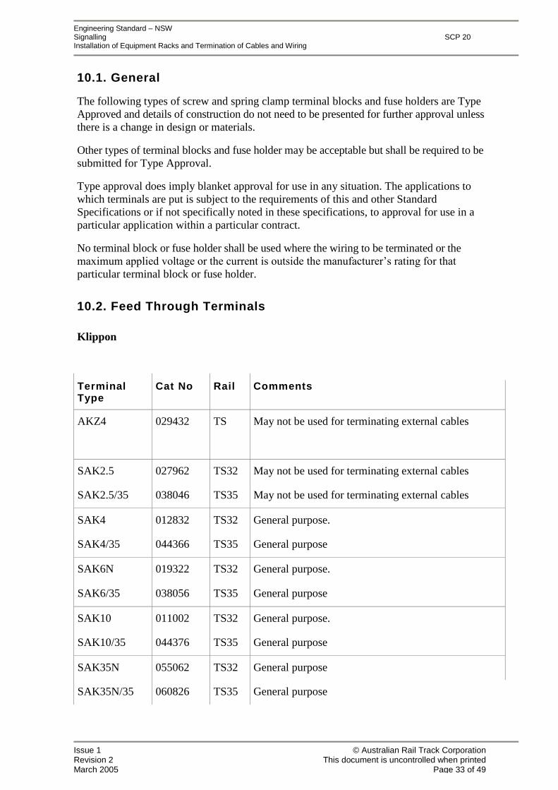
10.1. General
The following types of screw and spring clamp terminal blocks and fuse holders are TypeApproved and details of construction do not need to be presented for further approval unlessthere is a change in design or materials.
Other types of terminal blocks and fuse holder may be acceptable but shall be required to besubmitted for Type Approval.
Type approval does imply blanket approval for use in any situation. The applications towhich terminals are put is subject to the requirements of this and other StandardSpecifications or if not specifically noted in these specifications, to approval for use in aparticular application within a particular contract.
No terminal block or fuse holder shall be used where the wiring to be terminated or themaximum applied voltage or the current is outside the manufacturer’s rating for that particular terminal block or fuse holder.
10.2. Feed Through Terminals
Klippon
TerminalType
Cat No Rail Comments
AKZ4 029432 TS May not be used for terminating external cables
SAK2.5 027962 TS32 May not be used for terminating external cables
SAK2.5/35 038046 TS35 May not be used for terminating external cables
SAK4 012832 TS32 General purpose.
SAK4/35 044366 TS35 General purpose
SAK6N 019322 TS32 General purpose.
SAK6/35 038056 TS35 General purpose
SAK10 011002 TS32 General purpose.
SAK10/35 044376 TS35 General purpose
SAK35N 055062 TS32 General purpose
SAK35N/35 060826 TS35 General purpose
Engineering Standard–NSWSignalling SCP 20Installation of Equipment Racks and Termination of Cables and Wiring
Issue 1 © Australian Rail Track CorporationRevision 2 This document is uncontrolled when printedMarch 2005 Page 34 of 49
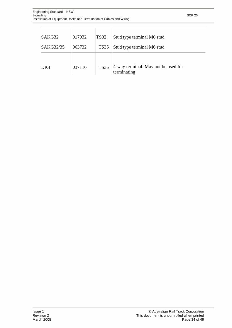
SAKG32 017032 TS32 Stud type terminal M6 stud
SAKG32/35 063732 TS35 Stud type terminal M6 stud
DK4 037116 TS35 4-way terminal. May not be used forterminatingexternal cables

Engineering Standard–NSWSignalling SCP 20Installation of Equipment Racks and Termination of Cables and Wiring
Issue 1 © Australian Rail Track CorporationRevision 2 This document is uncontrolled when printedMarch 2005 Page 35 of 49
Wago
Terminal Cat No Rail Comments
279-101 , 279-104 TS35 Non-vital only.
279-102 , 279-105 TS32 Non-vital only
280-101 , 280-104 TS35 May not be used to terminate external cables.
280-102 , 280-105 TS32 May not be used to terminate external cables.
281-101 , 281-104 TS35 General Pur pose.
281-102 , 281-105 TS32 General Purpose
282-101 , 282-104 TS35 General Purpose.
282-102 , 282-105 TS32 General Purpose
284-101 , 284-104 TS35 General Purpose.
284-102 , 284-105 TS32 General Purpose
283 104 TS32 General Purpose
283-102 , 283-105 TS32 General Purpose
4-way terminal. May not be used to terminateexternal cable
280-646 , 280-656 4-way terminal. May not be used to terminateexternal cable
280-641 , 280-651 TS35 3-way terminal. May not be used to terminateexternal cable
TS32 3-way terminal. May not be used to terminateexternal cable
281-631 , 280-651 3-way terminal block.
- 101 ,.
Engineering Standard–NSWSignalling SCP 20Installation of Equipment Racks and Termination of Cables and Wiring
Issue 1 © Australian Rail Track CorporationRevision 2 This document is uncontrolled when printedMarch 2005 Page 36 of 49
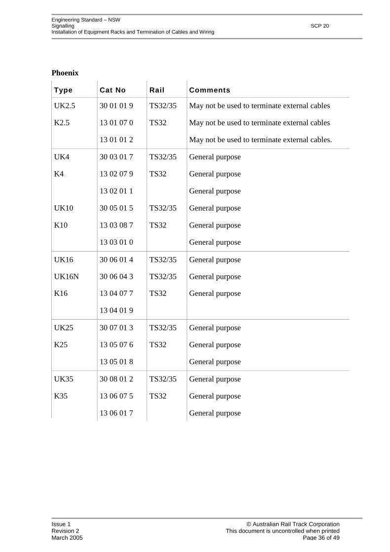
Phoenix
Type Cat No Rail Comments
UK2.5 30 01 01 9 TS32/35 May not be used to terminate external cables
K2.5 13 01 07 0 TS32 May not be used to terminate external cables
13 01 01 2 May not be used to terminate external cables.
UK4 30 03 01 7 TS32/35 General purpose
K4 13 02 07 9 TS32 General purpose
13 02 01 1 General purpose
UK10 30 05 01 5 TS32/35 General purpose
K10 13 03 08 7 TS32 General purpose
13 03 01 0 General purpose
UK16 30 06 01 4 TS32/35 General purpose
UK16N 30 06 04 3 TS32/35 General purpose
K16 13 04 07 7 TS32 General purpose
13 04 01 9
UK25 30 07 01 3 TS32/35 General purpose
K25 13 05 07 6 TS32 General purpose
13 05 01 8 General purpose
UK35 30 08 01 2 TS32/35 General purpose
K35 13 06 07 5 TS32 General purpose
13 06 01 7 General purpose
Engineering Standard–NSWSignalling SCP 20Installation of Equipment Racks and Termination of Cables and Wiring
Issue 1 © Australian Rail Track CorporationRevision 2 This document is uncontrolled when printedMarch 2005 Page 37 of 49
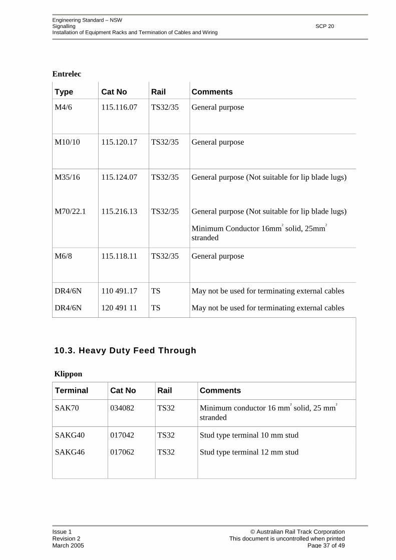
Entrelec
Type Cat No Rail Comments
M4/6 115.116.07 TS32/35 General purpose
M10/10 115.120.17 TS32/35 General purpose
M35/16 115.124.07 TS32/35 General purpose (Not suitable for lip blade lugs)
M70/22.1 115.216.13 TS32/35 General purpose (Not suitable for lip blade lugs)
Minimum Conductor 16mm² solid, 25mm²
stranded
M6/8 115.118.11 TS32/35 General purpose
DR4/6N 110 491.17 TS May not be used for terminating external cables
DR4/6N 120 491 11 TS May not be used for terminating external cables
10.3. Heavy Duty Feed Through
Klippon
Terminal Cat No Rail Comments
SAK70 034082 TS32 Minimum conductor 16 mm² solid, 25 mm²
stranded
SAKG40 017042 TS32 Stud type terminal 10 mm stud
SAKG46 017062 TS32 Stud type terminal 12 mm stud

Engineering Standard–NSWSignalling SCP 20Installation of Equipment Racks and Termination of Cables and Wiring
Issue 1 © Australian Rail Track CorporationRevision 2 This document is uncontrolled when printedMarch 2005 Page 38 of 49
Phoenix
Terminal Cat No Rail Comments
UKH95 30 10 013 TS32/35 Minimum conductor 25 mm²
UKH150 30 10 110 TS32/35 Minimum conductor 35 mm²
UKH240 30 10 217 TS32/35 Minimum conductor 95 mm²
UHV25M8/M8 21 30 208 TS32/35 Stud type terminal 8 mm stud
UHV50M10/M10 21 30 211 TS32/35 Stud type terminal 10 mm stud
UHV95M12/M12 21 30 224 TS32/35 Stud type terminal 12 mm stud
UHV150M12/M12 21 30 237 TS32/35 Stud type terminal 12 mm stud
Entrelec
Terminal Cat No Rail Comments
M35/26.FF 115 140 23 TS32/35 Stud type terminal
M120/35.FF 115 146 15 TS32/35 Stud type terminal
M300/42.FF 115 149.20 TS32/35 Stud type terminal
M35/26EE 115.151.12 TS32/35 Stud type terminal
M150/35EE 115 156 17 TS32/35 Stud type terminal
Engineering Standard–NSWSignalling SCP 20Installation of Equipment Racks and Termination of Cables and Wiring
Issue 1 © Australian Rail Track CorporationRevision 2 This document is uncontrolled when printedMarch 2005 Page 39 of 49
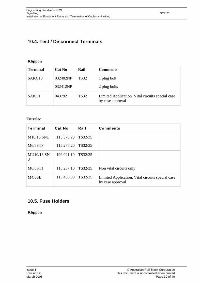
10.4. Test / Disconnect Terminals
Klippon
Terminal Cat No Rail Comments
SAKC10 032402NP
032412NP
TS32 1 plug bolt
2 plug bolts
SAKT1 043792 TS32 Limited Application. Vital circuits special caseby case approval
Entrelec
Terminal Cat No Rail Comments
M10/16.SN1
M6/8STP
115 376.23
115 277.20
TS32/35
TS32/35
MU10/13.SN3
199 021 10 TS32/35
115 237.10 TS32/35M6/8ST1 Non vital circuits only
M4/6SB 115.436.00 TS32/35 Limited Application. Vital circuits special caseby case approval
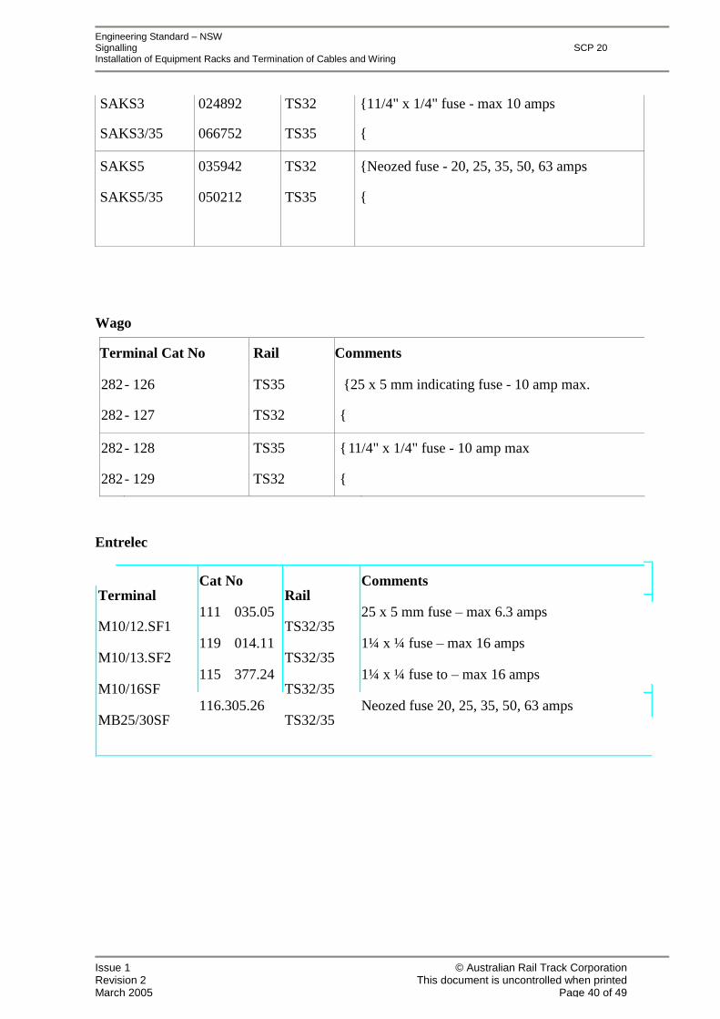
10.5. Fuse Holders
Klippon
Engineering Standard–NSWSignalling SCP 20Installation of Equipment Racks and Termination of Cables and Wiring
Issue 1 © Australian Rail Track CorporationRevision 2 This document is uncontrolled when printedMarch 2005 Page 40 of 49
SAKS3
SAKS3/35
024892
066752
TS32
TS35
{11/4" x 1/4" fuse - max 10 amps
{
SAKS5 035942 TS32 {Neozed fuse - 20, 25, 35, 50, 63 amps
SAKS5/35 050212 TS35 {
Wago
Terminal Cat No Rail Comments
282- 126 TS35 {25 x 5 mm indicating fuse - 10 amp max.
282- 127 TS32 {
282- 128 TS35 {11/4" x 1/4" fuse - 10 amp max
282- 129 TS32 {
Entrelec
Terminal
M10/12.SF1
M10/13.SF2
M10/16SF
MB25/30SF
Cat No
111 035.05
119 014.11
115 377.24
116.305.26
Rail
TS32/35
TS32/35
TS32/35
TS32/35
Comments
25 x 5 mm fuse–max 6.3 amps
1¼ x ¼ fuse–max 16 amps
1¼ x ¼ fuse to–max 16 amps
Neozed fuse 20, 25, 35, 50, 63 amps
Engineering Standard–NSWSignalling SCP 20Installation of Equipment Racks and Termination of Cables and Wiring
Issue 1 © Australian Rail Track CorporationRevision 2 This document is uncontrolled when printedMarch 2005 Page 41 of 49
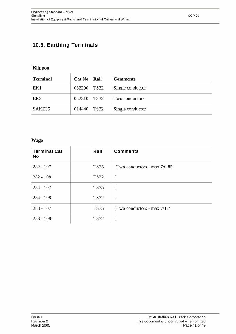
10.6. Earthing Terminals
Klippon
Terminal Cat No Rail Comments
EK1 032290 TS32 Single conductor
EK2 032310 TS32 Two conductors
SAKE35 014440 TS32 Single conductor
Wago
Terminal CatNo
Rail Comments
282 - 107 TS35 {Two conductors - max 7/0.85
282 - 108 TS32 {
284 - 107 TS35 {
284 - 108 TS32 {
283 - 107 TS35 {Two conductors - max 7/1.7
283 - 108 TS32 {
Engineering Standard–NSWSignalling SCP 20Installation of Equipment Racks and Termination of Cables and Wiring
Issue 1 © Australian Rail Track CorporationRevision 2 This document is uncontrolled when printedMarch 2005 Page 42 of 49
11. Appendix B
Installation Procedures - Cable To Rail Connections
Engineering Standard–NSWSignalling SCP 20Installation of Equipment Racks and Termination of Cables and Wiring
Issue 1 © Australian Rail Track CorporationRevision 2 This document is uncontrolled when printedMarch 2005 Page 43 of 49
11.1. Procedure A
Copper Bush and Tapered Bolt Style Rail Connections
Copper bush style rail connections may be used for the connection of:
track circuit cables (37/1.78mm),
impedance bond cables,
rail joint bonds (electrified areas),
traction negative busbar cables,
tie in bond cables,
to the rails and installed in accordance with Standard Drawing No. D08301 and thefollowing procedure:
1) Drill hole in the centre of the web using a sharp accurate machine twist or “Rotabroach” drill and using a water lubricant. (Oil shall not be used as part of the drilling process).Flat rail drills shall not be used.
2) Insert the copper bush from the outside of the track immediately the hole is drilled.
3) Insert the special three stage tapered punch as shown on Standard Drawing No. E08616sheet 1 into the copper bush in the direction in which the bush has been inserted andhammer in the first stage of the punch to expand the copper bush into the hole in the rail.
4) Remove the special punch, and hammer the stainless steel tapered bolt into the copperbush in the opposite direction from which the bush was inserted into the rail. (ie. fromthe inside of the track).
5) Check that the copper bush has not moved. If it has, remove the stainless steel taperedbolt and repeat the procedure nominated in 3 above using stage 2 of the special punch.The stainless steel tapered bolt shall then be re-inserted as nominated in 4 above.
6) Fit the track connections and nuts as shown on Standard Drawing No. D08301 and treatthe bolt thread with anti-seize.
7) Tighten the nut and locknuts on the tapered bolt to 55 ± 5 Nm.
Engineering Standard–NSWSignalling SCP 20Installation of Equipment Racks and Termination of Cables and Wiring
Issue 1 © Australian Rail Track CorporationRevision 2 This document is uncontrolled when printedMarch 2005 Page 44 of 49
11.2. Procedure B
Stainless Steel Grooved Channel Pin Rail Connections
Stainless steel grooved channel pin rail connections shall be used only for the connection ofsteel hypalon or 7/1.4mm un-insulated steel cables to rails and shall be installed in accordancewith the following procedure:
1) Drill hole in the centre of the web using a sharp accurate 7.1mm (9/32) machine twistdrill and using a water lubricant. (Oil shall not be used as part of the drilling process).
2) Bare 80mm in length of the insulation from the end of the steel hypalon cable.
3) Insert the flexible steel conductors directly into the hole from the outside of the rail untilthe insulation (where present) is 10mm from the rail.
4) Insert the grooved stainless steel channel pin with groove facing downward from theinside of the rail ensuring that the steel strands of the cable are bunched together andplaced in the groove of the channel pin.
5) Hammer the channel pin into the hole as far as possible.
Note: To prevent rusting of the hole, the fitting shall be installed immediately the hole isdrilled.
11.3. Procedure C
Stainless Steel Tapered Bolt Rail Connections
Copper hypalon cables (84 x 0.3mm) shall be connected to rails using stainless steel taperedbolts, nuts and lock washers installed in accordance with the following procedure:
1) Drill hole in the centre of the web using a sharp accurate machine 7/8twist drill andusing a water lubricant. (Oil shall not be used as part of the drilling process).
2) Hammer the tapered stainless steel bolt into the hole as far as possible, from the inside ofthe rail.
3) Fit the track connections as shown on Standard Drawing No. E08179/3.
Engineering Standard–NSWSignalling SCP 20Installation of Equipment Racks and Termination of Cables and Wiring
Issue 1 © Australian Rail Track CorporationRevision 2 This document is uncontrolled when printedMarch 2005 Page 45 of 49
11.4. Procedure D
Welded Stud Rail Connections (involving exothermic welding process)
11.4.1. Qualified Personnel
The connection of cable to rail using welded stud rail connections shall only be performed bypersons who have been trained and accredited in the application of welded stud railconnections by the supplier of the material being used or by a recognised signalling trainingorganisation.
Welded stud rail connections shall be installed in accordance with the following procedure:
11.4.2. Safety
1) Persons involved in the installation of welded stud rail connections shall wearappropriate protective clothing.
2) Equipment designed and constructed for welded stud installation shall be used.
3) Ensure the mould and the welding materials are free of moisture and contaminants.Contact of molten weld metal with moisture or contaminants may cause the weld metal tospurt out of the mould.
11.4.3. Weld Preparation
Before commencing the weld ensure:
1) The mould is not worn or broken. Worn or broken moulds may cause leakage of moltenweld metal and result in safety problems and unsatisfactory weld connections.
2) The mould fits the weld area and closes correctly.
3) The mould is securely attached to the rail using the manufacturer’s recommended rail clamp.
4) The mould is clean of slag from previous welds. (Foreign material shall be removed with ashort haired brush. Wire brushes or sharp implements shall not be used as these willshorten the life of the mould).
5) The mould is not wet or damp. (Wet or damp moulds will result in porous welds).Remove moisture from the mould using a hand operated butane torch or by firing acharge in the mould before making the desired weld.
Engineering Standard–NSWSignalling SCP 20Installation of Equipment Racks and Termination of Cables and Wiring
Issue 1 © Australian Rail Track CorporationRevision 2 This document is uncontrolled when printedMarch 2005 Page 46 of 49
11.4.4. Rail Preparation
1) Select the area on the rail for attachment of the stud. Ensure there is a minimum distanceof 80mm is between the proposed weld and any other weld. (This will prevent the secondbond cable applying pressure to the lug of the first bond at the weld location).
Do not attempt to apply stud over raised lettering on the rail web.
2) Grind off all mill scale and rust from the rail surface over the required area of the neutralaxis of the rail such that the area is bright, clean and dry.
Warm the weld area and remove any moisture using a gas torch.
3) Ensure the stud is completely clean. Studs shall be stored in a clean container with anairtight lid.
11.4.5. Igniter
Use a flint gun to ignite the cartridge. Ensure the flint gun is in good working order and willproduce enough spark to ignite the cartridge. Clean fouled up flint guns by soaking gun inhousehold ammonia.
11.5. Welding Procedure
1) Insert the clean bright stud into the mould making sure there is a minimum of 1mmbetween the stud and the rail. If this distance cannot be achieved, the mould is uneven orworn and should be replaced.
2) Secure the mould to the neutral axis of the rail making sure the mould is firmly againstthe clean bright web section of the rail.
3) Insert the steel disk, dished side up, directly centred over the hole in the bottom of thecrucible.
4) Pour the correct weld powder cartridge size into the crucible being careful not to disturbthe steel disk. The initial powder material will flow out of the container easily. Do notattempt to scrape the material out of the container.
5) Tap the bottom of the cartridge to loosen all the starting powder and spread the powderevenly over the top of the weld powder.
6) Close the safety lid.
7) Check the mould and crucible ensuring the arrangement is secure and safe for ignition.Stand upwind of the arrangement and aim the flint gun to the opening in the safety lidand ignite.
8) As soon as the charge ignites, withdraw the flint gun quickly.
9) Check that molten metal is not escaping from the mould during the welding process.
Engineering Standard–NSWSignalling SCP 20Installation of Equipment Racks and Termination of Cables and Wiring
Issue 1 © Australian Rail Track CorporationRevision 2 This document is uncontrolled when printedMarch 2005 Page 47 of 49
10) Allow approximately 20-30 seconds for the weld metal to solidify before opening themould.
11) Loosen the mould securing devices and remove the mould pulling directly and squarelyfrom the rail. Remove the sprue and any excess slag from the top of the rail.
12) Check that there has been no excess overflow of weld metal which indicates anunsatisfactory porous weld. Check also that the surface of the copper boss around thestud is smooth and clean.
11.6. Fixing Cables to Studs
Fit the cable lugs onto the studs, treat the threads with anti-seize and tighten nuts andlocknuts to 50 ± 5 Nm.
Engineering Standard–NSWSignalling SCP 20Installation of Equipment Racks and Termination of Cables and Wiring
Issue 1 © Australian Rail Track CorporationRevision 2 This document is uncontrolled when printedMarch 2005 Page 48 of 49
12. Appendix C
“Y”-link Rail Head Welded Connection
Engineering Standard–NSWSignalling SCP 20Installation of Equipment Racks and Termination of Cables and Wiring
Issue 1 © Australian Rail Track CorporationRevision 2 This document is uncontrolled when printedMarch 2005 Page 49 of 49
12.1. General
This method of connection to the rail uses the ‘Cadweld’ system of welding 70mmcopper cable to the outside of the head of the rail.
12.2. Applicability
This method of connection may be used with the following traction bonding cables:
608/0.5 copper
962/0.5 copper
962/0.5 Aluminium
494/0.5 Aluminium
12.3. Materials required
Cable Cadweld Crimp Link Heat Shrink Crimping DieBond Tube
608/.05 355mm CASR 199/120 RSA 40/12 TK- HT-130-C-150Copper 125
962/0.5 355mm CASR 199/185 RSA 40/12 TK- 38-223A1Copper 125
962/0.5 355mm BLK 182/199 40/12 TK- HT-150/185 A1Aluminium 125
494/0.5Aluminium
355mm(half only)
BLK 97/70 RSA 34/7 TK-100 HT-95/120 A1
12.4. Description
For 608/0.5 and 962/0.5 copper and 962/0.5 aluminum cables the connection consists of the355mm Cadweld bond cut in half with the two ends inserted into the nominated crimp linkand crimped to the end of the bonding cable. The nominated heat shrink sleeve is placed overthe link and cable (not over the Cadweld bond). The Cadweld bonds are then welded to the railhead using the Cadweld process.
For the 494/0.5 aluminum cable the connection consists of one half of a 355mm Cadweldbond inserted into the nominated crimp link and crimped to the end of the bonding cable.The nominated heat shrink sleeve is placed over the link and cable (not over the Cadweldbond). The Cadweld bond is then welded to the rail head using the Cadweld process.


![COMPACT COMPONENT SYSTEM HX-GX7 - JVCresources.jvc.com/Resources/00/00/95/GVT0124-001A.pdf · 2004. 2. 16. · SP-HXGX7 CA-HXGX7 SP-HXGX7 00-00_Cover[J].fmPage1Friday,January16,20045:31PM.](https://static.fdocuments.us/doc/165x107/60acb6f3f9d17f4855633841/compact-component-system-hx-gx7-2004-2-16-sp-hxgx7-ca-hxgx7-sp-hxgx7-00-00coverjfmpage1fridayjanuary162004531pm.jpg)


