Scottish Hydro Electric Power Distribution Project...
23
Scottish Hydro Electric Power Distribution Project Description Yell – Unst North (1) Yell – Unst South (2) Section ID 151, 152 SHEPD
Transcript of Scottish Hydro Electric Power Distribution Project...

Scottish Hydro Electric Power Distribution
Project Description
Yell – Unst North (1)
Yell – Unst South (2)
Section ID 151, 152
SHEPD

Project Description
Page 2 of 23
Contents Definitions and Abbreviations ................................................................................................................. 3
1. Introduction ................................................................................................................................... 4
2. Background .................................................................................................................................... 5
3. Proposed cable construction ........................................................................................................ 6
4. Pre-installation survey requirements ........................................................................................... 7
5. Project description ...................................................................................................................... 12
5.1. The existing route ................................................................................................................................................... 12
5.2. The proposed route ................................................................................................................................................ 12
5.3. The proposed installation methods ........................................................................................................................ 15
5.4. Proposed cable protection methods ....................................................................................................................... 18
5.5. The proposed delivery programme......................................................................................................................... 19
6. UXO Strategy ............................................................................................................................... 19
Appendix A: Existing cable routes with bathymetry ............................................................................ 20
Appendix B: Proposed cable routes ...................................................................................................... 21
Appendix C: Proposed Yell – Unst North (1) cable RPL ......................................................................... 22
Appendix D: Proposed Yell – Unst South (2) cable RPL ........................................................................ 23

Project Description
Page 3 of 23
Definitions and Abbreviations
The following definitions are used within this document:
SSEN Scottish and Southern Electricity Networks SHEPD Scottish Hydro Electric Power Distribution plc Cable SHEPD submarine electricity cable network Contractor Submarine cable installation company
The following abbreviations and definitions may be used within this document:
AtoN Aid to Navigation CLV Cable Lay Vessel DSV Dive Support Vessel DWA Double Wire Armoured HDD Horizontal Directional Drilling HVAC High-Voltage Alternating Current KP Kilometre Point kV kilovolt MAIB Marine Accident Investigation Branch MHWS Mean High Water Springs ML Marine Licence MLWS Mean Low Water Springs MSL Mean Sea Level ODN Ordnance Datum Newlyn OHL Overhead Line PAC Pre-Application Consultation PPY Poly Propylene Yarn PSD Particle Size Distribution ROV Remotely Operated Vehicle RPL Route Position List SAC Special Area of Conservation SBP Sub-Bottom Profiler SNH Scottish Natural Heritage SWA Single Wire Armoured UXO Unexploded Ordnance XLPE Cross Linked Polyethylene

Project Description
Page 4 of 23
1. Introduction
1.1. Scottish Hydro Electric Power Distribution plc (SHEPD) proposes to install two replacement 33kV submarine electricity cables from Point of Grimsetter in Yell to Ness of Wadbister in Unst within the Shetland Isles.
1.2. This document provides a description of the project, detailing the physical construction of the cables, the proposed routeing, method of installation and operation of the cables.
1.3. This document should be read in conjunction with the:
Marine Licence Application Form Pre-Application Consultation report (appended by Cost Benefit Analysis model) Environmental Supporting Information Fishing Liaison and Mitigation Action Plan (covering all legitimate sea users) Construction Environment Management Plan Operation, Inspection, Maintenance and Decommissioning Strategy
Project Description
Page 5 of 23
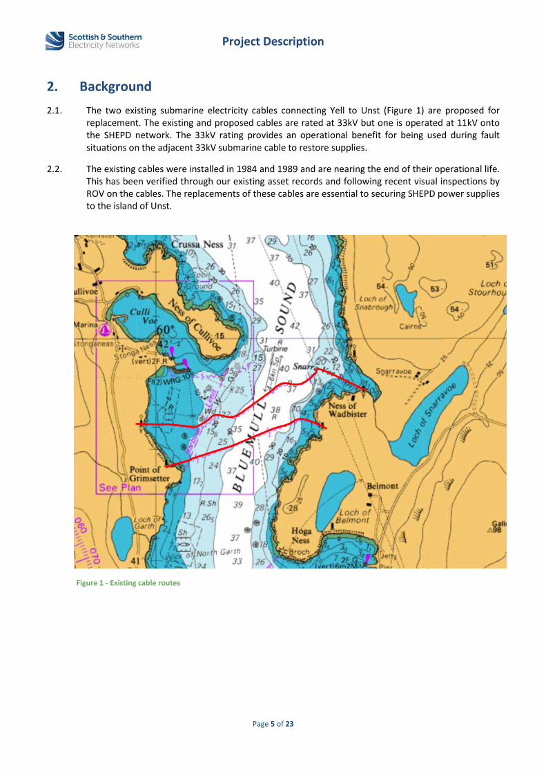
2. Background 2.1. The two existing submarine electricity cables connecting Yell to Unst (Figure 1) are proposed for
replacement. The existing and proposed cables are rated at 33kV but one is operated at 11kV onto the SHEPD network. The 33kV rating provides an operational benefit for being used during fault situations on the adjacent 33kV submarine cable to restore supplies.
2.2. The existing cables were installed in 1984 and 1989 and are nearing the end of their operational life. This has been verified through our existing asset records and following recent visual inspections by ROV on the cables. The replacements of these cables are essential to securing SHEPD power supplies to the island of Unst.
Figure 1 - Existing cable routes

Project Description
Page 6 of 23
3. Proposed cable construction 3.1. Electricity will be transmitted using HVAC submarine cable technology. The typical cable structure is
shown in Figure 2.
3.2. The proposed submarine cable consists of a three core design with copper round compacted stranded conductors, XLPE insulation, copper polyethylene laminated tape, polyethylene sheath, PPY, double galvanized steel wire armour, PPY, with one interstitial armoured optical fibre cable. The cable is rated at 33 kV HVAC, with an outer diameter of 118 mm and weight of 24.5 kg/m in water. The proposed cable construction is shown in Figure 3.
3.3. The three core design minimises the resultant electric and magnetic fields produced from the cable during operation. This is further reduced by balancing of the loads within each of the cable’s individual phases.
3.4. The proposed DWA construction will provide the cable with additional mechanical protection and will also help reduce the resultant electric and magnetic fields generated during operation of the cable in comparison with SWA cable constructions.
3.5. Fibre optics will be installed integral to the submarine cable for the purpose of cable condition monitoring, control and power system protection.
3.6. The submarine cable conductor specification and power rating has been selected through assessment of historic demand on the existing SHEPD network and with consideration of future customer demand growth on the network.
Figure 2 - Typical XLPE HVAC submarine cable structure
Source: ABB

Project Description
Page 7 of 23
1 Copper stranded conductors 2 Semiconductive waterblocking tape 3 Non-metallic screen 4 XLPE insulation 5 Non-metallic screen 6 Semiconductive waterblocking tape 7 Metallic screen 8 HDPE sheath 9 Non-hydroscopic fillers 10 Binding tape 11 PPY separator layer 12 Inner layer of galvanized steel armouring 13 PPY separator layer 14 Outer layer of galvanized steel armouring 15 PPY outer layers 16 Fibre optic
4. Pre-installation survey requirements 4.1. SHEPD previously appointed a Contractor to conduct marine surveys along the proposed cable
route. These surveys were undertaken over a 1000 m wide corridor between September and October in 2015. The main objectives of the marine survey was to identify:
seabed conditions (e.g. sand, rock, mud) to optimise the proposed cable route (avoidance of rock outcrops)
potential geological constraints, such as dykes, rock pinnacles, sand waves, incised channels etc.
locations of potential engineering constraints and/or safety hazards, such as existing pipelines and cables either in service or out of service, wrecks, marine debris, UXO etc.
areas of potential biological and ecological importance (such as biogenic and rocky reefs, priority marine features etc.) to allow habitat mapping and inform the requirement for additional surveys and assessment.
4.2. The surveyed corridor was centred along the existing cable routes. This was selected following a review of potential cable landing points on Yell and Unst, from previous ROV inspections of the existing cable and following an assessment of current and proposed sea user activities in the area. The presence of an existing fish farm to the south, tidal turbine to the north and harbour authority at Cullivoe also influenced the positioning for the survey corridor and routeing of the proposed cables.
4.3. The extent of the surveyed corridor was decided in consideration with survey cost, impact on environmental species from the survey equipment and also disruption to sea users from the survey
Figure 3 – Proposed XLPE HVAC submarine cable construction
Project Description
Page 8 of 23
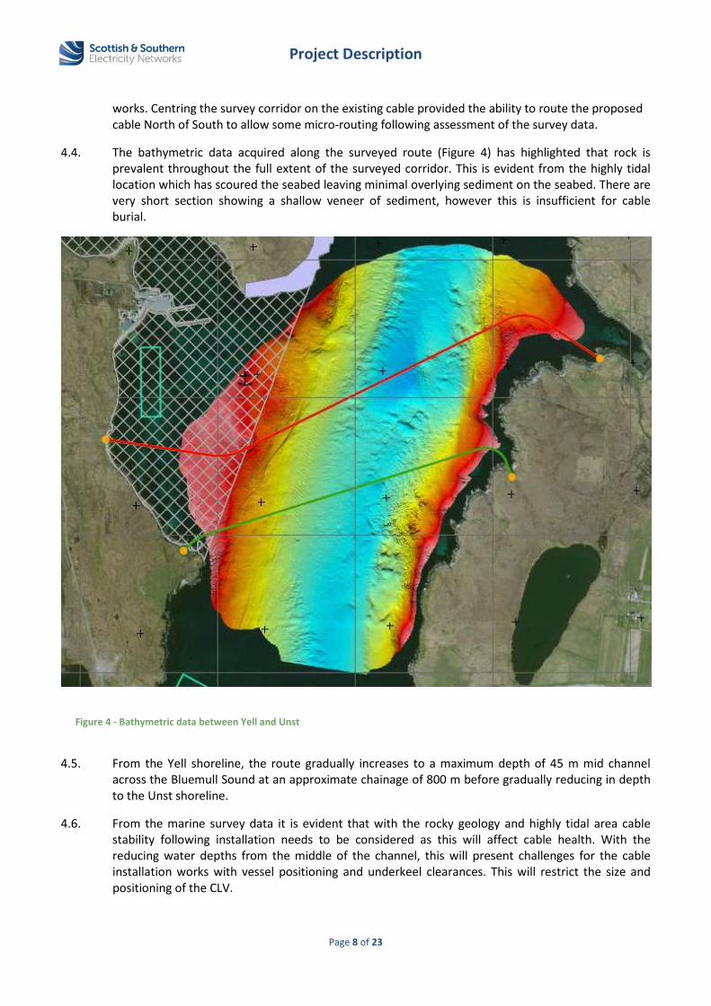
works. Centring the survey corridor on the existing cable provided the ability to route the proposed cable North of South to allow some micro-routing following assessment of the survey data.
4.4. The bathymetric data acquired along the surveyed route (Figure 4) has highlighted that rock is prevalent throughout the full extent of the surveyed corridor. This is evident from the highly tidal location which has scoured the seabed leaving minimal overlying sediment on the seabed. There are very short section showing a shallow veneer of sediment, however this is insufficient for cable burial.
4.5. From the Yell shoreline, the route gradually increases to a maximum depth of 45 m mid channel across the Bluemull Sound at an approximate chainage of 800 m before gradually reducing in depth to the Unst shoreline.
4.6. From the marine survey data it is evident that with the rocky geology and highly tidal area cable stability following installation needs to be considered as this will affect cable health. With the reducing water depths from the middle of the channel, this will present challenges for the cable installation works with vessel positioning and underkeel clearances. This will restrict the size and positioning of the CLV.
Figure 4 - Bathymetric data between Yell and Unst

Project Description
Page 9 of 23
4.7. Rocky areas are present at the intertidal areas around the shore at both Yell (Figure 5, Figure 6) and Unst which was further verified by site visits and site investigations. On Yell the rocky coastline extends north to the nearby harbour at Cullivoe. Further South on Yell a consented fish farm at Wick of North Garth restricts routeing of the cables to the South.
Figure 5 – Yell shore line looking north towards Cullivoe harbour
Figure 6 - Yell shore line looking south. Existing south cable AtoN in background

Project Description
Page 10 of 23
4.8. A decision was made to re-use the landfall location of the existing North cable on Yell with an offset from the existing cable. There is consent for a fish farm at this location however we have undertaken engagement with the developer and secured an agreement for existing and proposed cables. This positions both proposed cables within the Cullivoe harbour area which presents a higher risk to the cables and mariners however we have undertaken engagement, carried out an assessment of vessel movements in the area and conducted a cable burial risk assessment to support our proposal.
4.9. Similarly on Unst, the coastline is rocky and there are cliffs present along the coastline (Figure 7) limiting suitable cable landing locations for the proposed cables to the South of Ness of Wadbister. There is also a heritage area present near Loch Snarravoe which must be considered for any onshore based cable routeing or OHL works. Directly west of Loch Snarravoe is a sheltered bay (Figure 8) where both cables are proposed to come onshore.
4.10. The presence of an existing tidal turbine within the Bluemull Sound also limits cable routeing to the North.
4.11. SBP has been utilised to map the seabed surface to allow identification and extent of the sediment types. These survey methods are useful for identifying areas of the surveyed route that may be suitable for direct cable burial within the seabed or help to inform alternative cable protection methods if deemed required.
4.12. Limited geotechnical surveying was carried out along the route as the SBP data from the geophysical surveys indicated a lack of sediment along the extent of the surveyed corridor. The extent of geotechnical surveys was therefore restricted to seabed grab sampling at selected intervals. A number of grab sample attempts during the survey works failed to recover sufficient material due to a lack of sediment.
4.13. The purpose of this sampling was to carry out a benthic characterisation assessment combined with PSD analysis of the material at the seabed surface. The geotechnical sampling methods were intrusive in that there is a physical interaction between the sampling device and the sediments. Further and more intrusive geotechnical surveying would be required where direct cable burial is required along the route. This would provide information on soil conditions and suitability of burial equipment however as there is minimal sediment present, direct cable burial is not achievable. Any cable protection needed would be in the form of rock placement, rock filter bags or concrete mattressing directly over the cable.

Project Description
Page 11 of 23
Figure 7 - Unst shore line looking south. Existing south cable AtoN in background
Figure 8 - Unst sheltered bay West of Loch Snarravoe looking west

Project Description
Page 12 of 23
4.14. The pre-installation surveys have allowed SHEPD to optimise the cable routes within the survey corridor and helped to identify feasible installation and cable protection methods. The routeing has been refined following a review of seabed conditions, bathymetry, stakeholder views, seabed use and any other identified seabed features. In addition to this, further marine surveys will be undertaken during the summer of 2018 to better assess the engineering viability and environmental impact of the proposed cable routes and installation works.
4.15. As part of this additional survey, drop-down video and imagery surveys will also be undertaken to understand better the range of potential habitats and geographic spread. The methodology in relation to the surveys was developed through discussion with SNH. The survey outputs from the drop-down video surveys will be shared to evidence the habitats and features present along and in the vicinity of the proposed cables.
4.16. To support the marine licence and the proposed cable installation methodology a cable burial risk assessment and cable stability assessment will be completed to determine the level of protection needed and evaluate the impact of the proposed cable routes.
4.17. The additional surveys may influence our cable installation designs and routeing to help minimise the impact on the habitats and seabed features present on the route. This will allow identification of mitigation measures in the form of cable re-routing where appropriate, crossing locations for protective habitats, cable burial in areas suitable and also rock filter bag or concrete mattressing placement to stabilise the proposed cable to minimise movement along the seabed.
5. Project description
5.1. The existing route
5.1.1. The project is to install two replacement 33kV HVAC cables between Yell and Unst. The existing cable routes are installed from the Point of Grimsetter on Yell to Ness of Wadbister on Unst, across the Bluemull Sound (Figure 1). At each shore end landfall, the existing land-based network of OHL connects the submarine cables to the SHEPD network.
5.2. The proposed route
5.2.1. Following a review of the marine survey data, an optimum route for the proposed cables has been identified as shown in Figure 9. The proposed north cable will be 2.05 km within the marine environment between MHWS limits. However, the application length is 2.6 km to allow for obstacle avoidance during cable lay and tolerances with the cable lay operations. The proposed South cable will be 2.23 km within the marine environment between MHWS limits. However, the application length is 2.6 km to allow for obstacle avoidance during cable lay and tolerances with the cable lay operations.

Project Description
Page 13 of 23
5.2.2. The proposed cable routes lies within the survey corridor1 with some micro-routeing selected to avoid areas significant bedrock, boulders and avoid or minimise the impact on sensitive marine features identified from the surveys.
5.2.3. The Fetlar to Haroldswick MPA is located further South which has been considered for our proposed routeing by avoiding this area. Further information on this can be found in the Construction environment management plan.
5.2.4. The proposed cables retain the existing North cable shore end landfall at Yell. Alternative landfall positions were reviewed but discounted due the rocky coastline, harbour authority area to the North and locations of consented offshore developments.
5.2.5. The proposed cable routes will be laid adjacent to our existing North cable. An offset will be used to allow safe installation, operation, future maintenance and ongoing inspection of the cable(s).
5.2.6. On both Yell and Unst the proposed cables will be completed with short sections of underground cabling onto the existing SHEPD OHL. On Unst this will permit the dismantling of some sections of existing OHL.
5.2.7. The proposed cable route and method of installation has been identified based on a combination of desk studies, marine seabed surveys and stakeholder views. Prior to the cable installation, SHEPD’s
1 See section 4.2 for justification of how the corridor was selected.
Figure 9 - Proposed cable routes
Project Description
Page 14 of 23
appointed contractor will undertake a final review of the marine survey to confirm the seabed conditions and finalise the exact cable within the consented corridor and techniques to be employed.
5.2.8. Further to this, a review of the existing shore end landfall locations and land-based infrastucture was undertaken and verified with site visits on both Yell and Unst to confirm the shore end landing points and the method of cable installation above the MLWS limits. This was needed to assess the suitability for site access and the logistical constraints for plant and machinery but also better understand the environmental and landowner contraints.
5.2.9. An onshore cable installation by HDD was considered but discounted due to difficult ground conditions on Unst. The limited public road network would require significant civil improvements and the construction of a temporary or permanent roads would be required to permit the large machinery access to the cable landfall areas.
5.2.10. The area around the cable landfall on Yell and Unst is composed mainly of peat. This makes excavation and plant movements very difficult as it is very soft and boggy terrain. For the HDD works a large, level area of approximately 50 m by 50 m is required. The site needs to be stable to support the large drilling machinery during the setup and drilling operations. With the unstable ground on Yell and Unst, this will require extensive and expensive civil improvement works.
5.2.11. Extensive civil works could be impacted by archaelogical presence in the area. This will require extensive pre-construction surveys with agreements from land owners and tenants but also increases the risk of archaelogical impacting on the works. The additional works will likely increase the difficulty of acquiring the consents to carry out the works.
5.2.12. On Unst, modifications to the land based infrastructure by undergrounding a number of sections of OHL would have operational benefit and improve future access. This would also provide environmental and visual benefits to the local landowners and bird species. The amount of undergrounding may be impacted however by the difficult ground conditions.
5.2.13. As it is proposed to re-use the existing shore end landfall position on Yell, the existing AtoN warning beacon location will be retained. Similarly on Unst there is a suitably positioned AtoN that will be reused. Any ongoing maintenance and inspections associated with the warning beacon will be carried out on a regular basis to ensure they are in good condition for sea user safety. Further details can be found in the Operation, inspection, maintenance and decommissioning strategy.
5.2.14. The proposed cable route and installation method, including associated land based works, have been informed following a review of the marine survey data and cable inspections, stakeholder feedback from consultations and environmental constraints2 whilst balancing SHEPD’s electricity licence obligations. Details of the proposed RPL for the cable route from MHWS limits from Yell to Unst is located within Appendix C and Appendix D.
5.2.15. In addition to this, more focussed investigations and studies have been carried out along the proposed cable routes and working areas affected by the works by SHEPD’s archaeological and ecological consultant on both Yell and Unst. This has helped to firstly identify archaeological /ecological interests and then to help eliminate and/or mitigate any potential impacts from the proposed works within cultural heritage sites and/or environmentally sensitive locations.
2 Environmental constraints are detailed in Construction environment management plan
Project Description
Page 15 of 23
5.3. The proposed installation methods
5.3.1. For the cable laying activities, a CLV will be used. Additional smaller support vessels will be required at each of the shallower shore locations; this is likely to be a multicat/DSV. This may require an anchoring system to be laid out prior to and during works in the nearshore region. An anchor handling vessel would be required to lay out the anchors. A guard vessel is also likely to be used during the cable lay operations in order to ensure other vessels remain outside the area of operations to reduce collision risk.
5.3.2. Initially, the proposed submarine cables will be surface laid on the seabed across the length of the route. Due to the strong tidal currents the majority of the proposed cable routes will be across rocky seabed with very little overlying sediment. With limited sediment, direct cable burial will not be possible. By initially surface laying the cables, the footprint is minimised although cable mobility may increase the footprint and impact on the seabed habitat.
5.3.3. To minimise the impact of the cable on the seabed during and after installation, SHEPD plan to lay rock filter bags (each with a seabed footprint of approximately 2.0 m by 2.0 m) or concrete mattresses (each with a seabed footprint of approximately 3.0 m by 6.0 m) in spot locations on the cable to pin the cable to the seabed. Only clean washed stone will be used to fill the rock bags and no cementitious material will be used. Each bag shall be no more than 1.0 m high when installed. The rock filter bags have been proven to provide a habitat for aquatic species and mould to the seabed contours where installed.
5.3.4. Positioning of the rock bags or mattresses will help stabilise the cable. The risk of installing the rock bags or mattresses directly onto the cable could cause subsequent damage from point loading dependant on the seabed and lay of the cable. This may also increase the tension on the cable and potential for cable suspensions either side of the rock bag or mattress positions, which increases mariner safety from potential snagging incidents. A post lay inspection of the cable after it is installed will identify the potential risk to placement of the rock filter bag or mattreses directly onto the cable and confirm exact locations.
5.3.5. We will be undertaking a cable stability assessment to support our Marine Licence application that will help us to inform the cable stability throughout the proposed route with a view of minimising the amount of rock bags or concrete mattresses required to pin the cable whilst ensuring cable stability following the installation. This will help inform the required rock bag or mattress separation.
5.3.6. From Yell, with the location of the proposed fish farm and potential risk to the cable from moorings, we propose to lay rock filter bags and mattresses to fully cover the cable over a distance of 200 m. For the remainder of the route towards Unst, rock filter bags or mattresses will be placed on the cable at roughly 50 m intervals within the marine environment. The rock bags will help stabilise the cable, thus preventing damage caused by cable movement on the seabed following installation.
5.3.7. In summary, for our North cable we propose to install a maximum of 75 rock filter bags or concrete mattresses along the route, depending on cable stability study and cable burial risk assessement. Our cable installation and burial methodology for the North cable is summarised in Table 1.

Project Description
Page 16 of 23
Location along the cable route Installation type Length of
cable (m) No rock filter
bags/concrete mattresses
From termination point with existing OHL to Yell
shoreline
Cable burial by open-cut trench from termination point with OHL through field 170 0
From Yell shoreline to MLWS
Cable lay with up to 100 m of cast iron split pipe protection 100 0
From Yell shoreline across to KP0.5
Rock filter bags/mattresses installed directly on the cable with complete
coverage within fish farm development area
200 35
From KP0.5 to Unst shoreline KP2.22
Rock filter bags/mattresses installed directly on the cable at 50m minimum
spaced intervals 1,650 40
From MLWS to Unst shoreline
Cable lay with up to 100 m of cast iron split pipe protection 100 0
From Unst shoreline to termination point with OHL
Cable burial by open-cut trench from termination point with OHL through field 930 0
Total (marine cable length) 2,050 m 75
Table 1 –North cable installation, burial and protection
5.3.8. In summary, for our South cable we propose to install a maximum of 75 rock filter bags or concrete mattresses along the route, depending on cable stability study and cable burial risk assessement. Our cable installation and burial methodology for the Sorth cable is summarised in Table 2.
Location along the cable route Installation type Length of
cable (m) No rock filter
bags/concrete mattresses
From termination point with existing OHL to Yell
shoreline
Cable burial by open-cut trench from termination point with OHL through field 240 0
From Yell shoreline to MLWS
Cable lay with up to 100 m of cast iron split pipe protection 100 0
From MLWS on Yell to KP0.5
Rock filter bags/mattresses installed directly on the cable with complete
coverage within fish farm development area
200 35
From KP0.5 to MLWS on Unst
Rock filter bags/mattresses installed directly on the cable at 50m minimum
spaced intervals 1,830 40
From MLWS to Unst shoreline
Cable lay with up to 100 m of cast iron split pipe protection 100 0
From Unst shoreline to termination point with OHL
Cable burial by open-cut trench from termination point with OHL through field 680 0
Total (marine cable length) 2,230 m 75
Table 2 – South cable installation, burial and protection

Project Description
Page 17 of 23
5.3.9. At Yell and Unst, to complete the shore end installation works there will be some underground cabling from the transition joint location with the marine cable and minor modifications to the existing 33kV OHL.
5.3.10. It is proposed to install the cable by using an open-cut trench method of installation inshore from the MLWS tidal limits at both shore end landfall locations. An open cut trench will be excavated to install and bury the cable. This will utilise traditional terrestrial based plant including excavators at low tide. The typical underground cable trench is illustrated below in Figure 8. To allow for micro-routing during cable installation the landfall excavation works will take place within 100 m either side of the cable landfall positions shown.
5.3.11. The trench will be excavated alongside the cable using a terrestrial-based mechanical excavator during low spring tide. The excavated material will be placed to one side of the trench for later reinstatement. Using a mechanical winch and cable rollers, the cable will be manoeuvred into the bottom of the trench and then covered with the excavated material using the mechanical excavator. The trench width will be minimised where possible however will be dependent on ground stability but will typically be 1 m wide. The target depth of the trench will be 1.25 m. Temporary trench shoring may be required to prevent collapse of the trench wall. The footprint of the excavator may be up to 5 m, and a working width, including for the temporary storage of removed material, would be in the order of 10 m.
5.3.12. On either shore where sufficient burial cannot be achieved, cast iron split pipe will be fitted around the cable for additional protection in the event of exposure (Figure 9). This will be installed down to MLWS mark. We propose to install a maximum of 100 m of split pipe protection on each shore from MWHS to MLWS in the event that we can’t achieve sufficient cable burial to protect the cable. The split pipe is an articulated cast iron shell design that locks around the cable and fixed with bolted end clamps. There are a number of suppliers with differing shell designs and weights. As a guide each shell has an 8 mm wall thickness, with an effective length of 391 mm and combined weight in air of 39.96 kg/m.
Figure 8 - Open cut cable trench cross section inshore of MWS limit

Project Description
Page 18 of 23
5.3.13. The intertidal cable will be connected to the terrestrial cable in a transition joint pit buried in the ground located above the MHWS limit at each end. At the Yell end, from MHWS limit the cable will be buried onshore for approximately 150 m connect into the existing OHL. On the Unst shore, from the MHWS limit the cable will be buried for approximately 900 m through the field and connect in to the OHL. This will permit the dismantling several spans of existing OHL.
5.3.14. On completion of jointing and cabling works, spoil material will be backfilled into the trenches and the shore will be reinstated; grassed areas will be left to re-seed naturally. The upper surface layer will be stripped and stockpiled separately to allow a quicker reinstatement.
5.3.15. At each shore landfall location, to facilitate the onshore works and ensure compliance with the Construction (Design and Management) Regulations 2015, a temporary site area will be required, approximately 30 m x 30 m in size, to provide welfare facilities and parking during the works. To minimise ground disturbance, ease reinstatement and recovery, the area will be covered with a membrane material and levelled with rock chippings.
5.3.16. SHEPD’s Cost Benefit Analysis Methodology3 is used as evidence that the solution proposed in this project description represents the best value4 installation method of this submarine electricity cable route. The modelling recommended that rock placement (or rock bags) should be used to reduce the risk to marine users, stablise the cable and balance the views of the different stakeholders who we engaged with. The final CBA recommendation suggested that approximately 530m of rockplacment should be installed to achieve these objectives. The current solition for both the Yell to Unst cables to be:
Initially surface lay the cables along the sea bed Install a maximum of 75 rock filter bags or concrete mattresses directly over the cable Install a maximum of 200 m of cast iron shells
This solution would be able to achieve the same objective, outlined by the CBA model, but at a higher projected societal value and lower disruption to the marine environment by reducing the level of rock bags. It is therefore proposed to deviate from the CBA final recommendation.
5.3.17. A summary of the Cost Benefit Analysis model can be found in the Pre-Application Consultation report.
5.4. Proposed cable protection methods
3 http://news.ssen.co.uk/media/147004/4731-ssepd-submarine-cables-doc-july-2016_06.pdf 4 Which we define as best balancing the health and safety, environmental, socio-economic, wider-engineering and economic considerations whilst meeting regulatory obligation.
Figure 9 – Diagram of split pipe protection

Project Description
Page 19 of 23
5.4.1. The cable installation method within the marine environment from each MLWS location will initially be surface laid across the length of the route. The proposed installation methods are less intrusive and allow for quicker installation duration. Due to the strong tidal currents along the route, rocky seabed and to minimise impact on protected habitats, it is planned to lay rock filter bags or concrete mattresses in spot locations on the cables at intervals along the route to pin the cable to the seabed ensuring stability.
5.4.2. As evidenced form the marine surveys due to a lack of sediment, we are not proposing to bury the cables within the marine environment however at the intertidal areas at both shore end landfall locations it is proposed to use an open cut trench method to install the cables down to the MLWS tidal limits.
5.4.3. On either shore above the MLWS limit, where sufficient cable burial cannot be achieved, cast iron split pipe will be fitted around the cable for additional protection in the event of exposure. On both Yell and Unst shore lines we propose to install a maximum of 100 m of split pipe on each cable for additional protection.
5.4.4. This change to the cable design methodology follows consideration of comments and/or objections received at the PAC Events as detailed in the Pre-Application Consultation report.
5.5. The proposed delivery programme
5.5.1. Ecological protected sites and marine archaeological sites as well as priority marine features and receptors have been considered in this application. For further information see, Environmental Supporting Information, Sections 2, 4, 5 and 6.
5.5.2. SHEPD propose to complete the submarine cable and onshore connection works during the months of October 2018 – March 2019 or before if the necessary consents have been secured. The planned duration of the works is no greater than 30 days, exclusive of weather.
5.5.3. The onshore cabling works on both Yell and Unst will be completed prior to the main submarine cable installation works. The minor modifications required to the existing OHL networks will be carried out during commissioning of the submarine cable to the SHEPD network. Replacement of the existing AtoNs will also be undertaken during the OHL works.
5.5.4. Following successful commissioning of the proposed cables onto the SHEPD network, the OHL dismantling works down to the existing cable landfalls on Unst will be undertaken and disposed of from site.
6. UXO Strategy
6.1. The Contractor appointed by SHEPD shall undertake an initial desktop study to assess the risk of UXO within the area of the cable route. In addition, if the desktop study identifies a high risk, a UXO survey along the cable route will be completed to detect any objects potentially UXO related. The results shall be used to inform cable routing within the consented corridor such that significant targets are avoided. If it is not possible to avoid a target, it shall be identified using an ROV or drop down camera. Alternatively where a UXO is encountered that cannot be avoided, a specialist Contractor shall be engaged to clear, recover or remove the target from the working area.

Project Description
Page 20 of 23
Appendix A: Existing cable routes with bathymetry

Project Description
Page 21 of 23
Appendix B: Proposed cable routes

Project Description
Page 22 of 23
Appendix C: Proposed Yell – Unst North (1) cable RPL
Position Name UTM30N
KP Latitude
Longitude
0.00 6730316.39 N 608972.64 E 0.17 6730354.75 N 606095.94 E 2.22 6730759.22 N 610985.02 E 3.15 6730937.09 N 611764.35 E

Project Description
Page 23 of 23
Appendix D: Proposed Yell – Unst South (2) cable RPL
Position Name UTM30N
KP Latitude
Longitude
0.00 6730266.46 N 609011.09 E 0.24 6730307.60 N 609099.32 E 2.47 6730604.28 N 611043.38 E 3.15 6730063.66 N 611194.40 E