Scope of this Document - Dataprobedataprobe.com/support/ibootbar/ibootbar.pdf · Scope of this...
37
iBootBar V1.3x Page 1 Technical Support Hotline: (201) 934-5111 [email protected] Main: 201-934-9944 Website: dataprobe.com Scope of this Document: This document covers the installation and operations of Dataprobe’s iBootBar series of remote power control units. The following models are covered in this document: Model Power Feed / Total Capacity Outlets Control iBB-N15 NEMA 15 Amp 8 x NEMA 5-15 IP Control, Serial Control iBB-N15-M NEMA 15 Amp 8 x NEMA 5-15 IP Control, Serial Control, Internal Modem iBB-2N15 2 x NEMA 30 Amp 8 x NEMA 5-15 IP Control, Serial Control iBB-2N15-M 2 x NEMA 30 Amp 8 x NEMA 5-15 IP Control, Serial Control, Internal Modem iBB-N20 NEMA 20 Amp 8 x NEMA 5-15 IP Control, Serial Control iBB-N20-M NEMA 20 Amp 8 x NEMA 5-15 IP Control, Serial Control, Internal Modem iBB-2N20 2 x NEMA 40 Amp 8 x NEMA 5-15 IP Control, Serial Control iBB-2N20-M 2 x NEMA 40 Amp 8 x NEMA 5-15 IP Control, Serial Control, Internal Modem iBB-C10 IEC C14 10 Amp 8 x IEC C13 IP Control, Serial Control iBB-C10-M IEC C14 10 Amp 8 x IEC C13 IP Control, Serial Control, Internal Modem iBB-2C10 2 x IEC C14 20 Amp 8 x IEC C13 IP Control, Serial Control iBB-2C10-M 2 x IEC C14 20 Amp 8 x IEC C13 IP Control, Serial Control, Internal Modem iBB-C20 IEC C20 20 Amp 8 x IEC C13 IP Control, Serial Control iBB-C20-M IEC C20 20 Amp 8 x IEC C13 IP Control, Serial Control, Internal Modem iBB-2C20 2 x IEC C20 40 Amp 8 x IEC C13 IP Control, Serial Control iBB-2C20-M 2 x IEC C20 40 Amp 8 x IEC C13 IP Control, Serial Control, Internal Modem iBootBar Installation and Operations Version 1.5 Ref: iBootBar_1.5_v031212e
-
Upload
trinhduong -
Category
Documents
-
view
215 -
download
1
Transcript of Scope of this Document - Dataprobedataprobe.com/support/ibootbar/ibootbar.pdf · Scope of this...
iBootBar V1.3x Page 1
Technical Support Hotline: (201) 934-5111 [email protected]
Main: 201-934-9944 Website: dataprobe.com
Scope of this Document: This document covers the installation and operations of Dataprobe’s iBootBar series of remote power control units. The following models are covered in this document:
Model Power Feed / Total Capacity Outlets Control
iBB-N15 NEMA 15 Amp 8 x NEMA 5-15 IP Control, Serial Control
iBB-N15-M NEMA 15 Amp 8 x NEMA 5-15 IP Control, Serial Control, Internal Modem
iBB-2N15 2 x NEMA 30 Amp 8 x NEMA 5-15 IP Control, Serial Control
iBB-2N15-M 2 x NEMA 30 Amp 8 x NEMA 5-15 IP Control, Serial Control, Internal Modem
iBB-N20 NEMA 20 Amp 8 x NEMA 5-15 IP Control, Serial Control
iBB-N20-M NEMA 20 Amp 8 x NEMA 5-15 IP Control, Serial Control, Internal Modem
iBB-2N20 2 x NEMA 40 Amp 8 x NEMA 5-15 IP Control, Serial Control
iBB-2N20-M 2 x NEMA 40 Amp 8 x NEMA 5-15 IP Control, Serial Control, Internal Modem
iBB-C10 IEC C14 10 Amp 8 x IEC C13 IP Control, Serial Control
iBB-C10-M IEC C14 10 Amp 8 x IEC C13 IP Control, Serial Control, Internal Modem
iBB-2C10 2 x IEC C14 20 Amp 8 x IEC C13 IP Control, Serial Control
iBB-2C10-M 2 x IEC C14 20 Amp 8 x IEC C13 IP Control, Serial Control, Internal Modem
iBB-C20 IEC C20 20 Amp 8 x IEC C13 IP Control, Serial Control
iBB-C20-M IEC C20 20 Amp 8 x IEC C13 IP Control, Serial Control, Internal Modem
iBB-2C20 2 x IEC C20 40 Amp 8 x IEC C13 IP Control, Serial Control
iBB-2C20-M 2 x IEC C20 40 Amp 8 x IEC C13 IP Control, Serial Control, Internal Modem
iBootBar Installation and Operations
Version 1.5
Ref: iBootBar_1.5_v031212e


iBootBar V1.5x Page 3
Table of Contents
Important Safety Instructions 4
Quick Start 5
General Overview 6
Installation 8 Rack Mounting Ethernet Serial Port Dial Line Expansion Power Source
Configuration 10 Setup and Control Utility Command Line Interface Setting the IP Address
Basic Operation 13 Web Interface Command Line Interface Outlet Commands User Commands Device Commands Group Commands Web Server Commands Telnet Commands AutoPing Commands Event Commands Firmware Upload Commands Email Commands Time Commands
Advanced Operation 26 DTMF Control Timed Events Auto Ping Email Notification SNMP Firmware Upgrades Password Recovery Setup and Control Utility
Specifications 34
Compliance Statements 35
Modem Certifications 36
SNMP MIB 37
Technical Support, Warranty 38
Page 4 iBootBar V1.5x
Important Safety Information When using this product, basic safety precautions should always be followed to reduce the risk of fire, electric shock, and injury to persons, including the following: Disconnect all power cords before servicing!
1. Read and understand all instructions.
2. Follow all warnings in the manual and marked on the product.
3. Unplug this product from the wall outlet before cleaning. Do not use liquid cleaners or aerosol cleaners. Use a damp cloth for cleaning.
4. Do not use this product in an outdoor environment or near water, for example, near a bath tub, wash bowl, kitchen sink, or laundry tub, in a wet basement, or near a swimming pool.
5. Do not place this product on an unstable cart, stand, or table. The product may fall, causing serious damage to the product.
6. Slots and openings in this product and the back or bottom are provided for ventilation to protect it from overheating, these openings must not be blocked or covered. The openings should never be blocked by placing the product on the bed, sofa, rug, or other similar surface. This product should never be placed near or over a radiator or heat register. This product should not be placed in a built-in installation unless proper ventilation is provided.
7. This product should be operated only from the type of power source indicated on the marking label. If you are not sure of the type of power supply to your home, consult your dealer or local power company.
8. This product is equipped with a three wire grounding type plug, a plug having a third (grounding) pin. This plug will only fit into a grounding type power outlet. This is a safety feature. If you are unable to insert the plug into the outlet, contact your electrician to replace your obsolete outlet. Do not defeat the safety purpose of the grounding type plug. Do not use a 3-to-2 prong adapter at the receptacle; use of this type adapter may result in risk of electrical shock and/or damage to this product.
9. Do not allow anything to rest on the power cord. Do not locate this product where the cord will be abused by persons walking on it.
10. Do not overload wall outlets and extension cords as this can result in the risk of fire or electric shock.
11. Never push objects of any kind into this product through slots as they may touch dangerous voltage points or short out parts that could result in a risk of fire or electrical shock. Never spill liquid of any kind on the product.
12. To reduce the risk of electrical shock, do not disassemble this product, but take it to a qualified serviceman when some service or repair work is required. Opening or removing covers may expose you to dangerous voltages or other risks. Incorrect re-assembly can cause electric shock when the appliance is subsequently used.
13. Unplug this product from the wall outlet and refer servicing to qualified service personnel under the following conditions:
a) When the power supply cord or plug is damaged or frayed.
b) If liquid has been spilled into the product.
c) If the product has been exposed to rain or water.
d) If the product does not operate normally by following the operating instructions. Adjust only those controls, that are covered by the operating instructions because improper adjustment of other controls may result in damage and will often require extensive work by a qualified technician to restore the product to normal operation.
e) If the product has been dropped or has been damaged.
f) If the product exhibits a distinct change in performance.
14. Avoid using a telephone (other than a cordless type) during an electrical storm. There may be a remote risk of electric shock from lightning.
15. Do not use the telephone to report a gas leak in the vicinity of the leak.
16. Do not exceed the maximum output rating of the auxiliary power receptacle.

iBootBar V1.5x Page 5
Quick Start
Front Panel
Rear Panel – NEMA Versions
Rear Panel – IEC Versions
Quick Start Defaults IP address 192.168.0.254 User Credentials Username: admin Password: admin Command Line Quick Start: To view outlet status iBootBar> get outlets To turn on off outlet 1 iBootBar> set outlet 1 off To reboot outlet 2 iBootBar> set outlet 2 cycle
Outlet Status Indicators
Reset Pushbutton (Recessed)
Mains (Inlet) Power Indicators
Linecord for NEMA Models
Circuit Breaker
2nd Linecord and Circuit Breaker on -2N Models
8 NEMA 5-15 Outlets
Serial (DCE)
Network (10/100)
Phone Line (Modem Versions)
Expansion for Cluster Configurations
8 IEC C13 Outlets
IEC C-14 (10 Amp) or IEC C-20 (20 Amp) Inlets
2nd Inlet and Circuit Breaker on -2C Models

Page 6 iBootBar V1.5x
General Overview
8 Independently controllable outlets
The iBootBar (iBB) series is designed to provide power distribution and remote power control. Each iBB allows eight outlets to be independently switched on and off for reboot, energy management and security. The iBB has many features to make the management of power distribution simple and cost effective:
Dual power inputs for redundant power feeds (some models)
Models with dual inputs (iBB-2N- or iBB-2C-) have two inlets (mains). Each main feeds four outlets Inlet A supports outlets 1-4 and Inlet B feeds 5-8. Dual power inlet models can be used to support higher current devices, as each inlet can carry its rated load, doubling the amperage of a single inlet device. Dual Inlet models can also be used to source power from two redundant sources, with each source feeding a power supply of a single device.
Support for dual redundant powered devices
In addition to two power sources, pairs of outlets can be linked together to allow simultaneous control. This allows a single command to power down devices with dual redundant power supplies.
Web Browser Control Simple web browser interface is easy to use and provides complete status information and control of the outlets, and groups.
Telnet/Serial CLI control Telnet and serial access use the same Command Line Interface (CLI ) structure and syntax to completely configure the iBootBar, or multiple iBootBars in a cluster configuration.
Multiple users with assigned rights and simultaneous control
Up to 16 users can be assigned administrator or user only rights, plus access to specific outlets and groups. Users only see the outlets and groups they are assigned to.
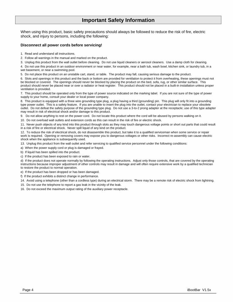
Multiple iBootBar Cluster Configuration
Up to 16 iBootBars can be linked together and controlled from a single web or CLI interface. One master iBootBar provides the communication to the users and continuously receives status information from the rest of the iBootBars in the cluster. Up to 128 outlets can be controlled in this manner from one IP address.
Grouping of outlets for simultaneous management
Multiple outlets, across multiple iBootBars in clustered configurations can be linked together in named groups and managed together. This allows for example, power cycling all devices of a certain type together.
AutoPing for automatic reboot of crashed systems
Up to 16 systems can be continuously monitored with AutoPing, with automatic power control upon loss of contact. Reboot crashed systems, or provide auto power-up or –down for environmental controls, and notification systems.
Real-Time event control Set automatic power actions based on your schedule. Restart systems every day to reduce memory bloat. Power up resources only when needed for energy management, lifecycle extension or security.
Internal Modem Option, Data or DTMF Control (some models)
Models with Suffix –M have internal modems with approvals in 36 countries. The modem supports data calls from terminal devices using the CLI, and direct dial from a tone telephone for simple on/off control when more sophisticated means are not available.
iBootBar V1.5x Page 7
SNMP manageable Setup and Control functions can be linked to any SNMP v1 compatible manager. The iBootBar MIB is downloadable from the website.
Syslog reporting All activity can be reported to a syslog compatible server.
iBootBar Cluster Configuration
Phone plus IP control
Page 8 iBootBar V1.5x
Installation
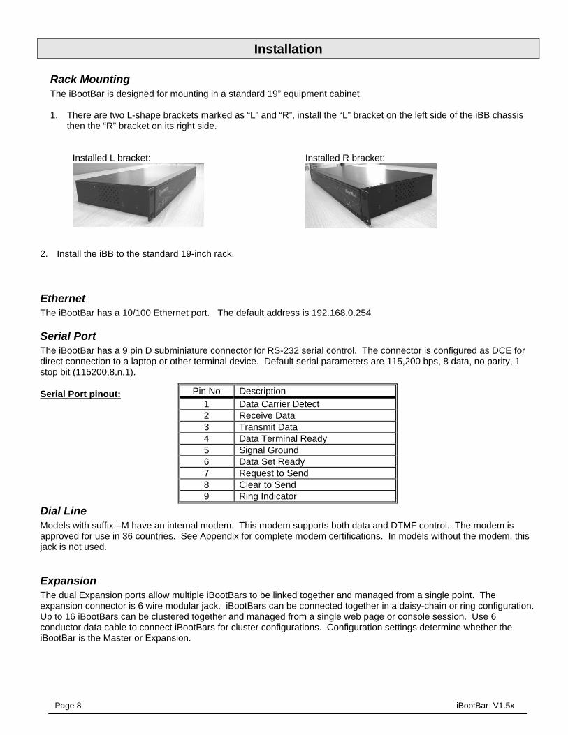
Rack Mounting The iBootBar is designed for mounting in a standard 19” equipment cabinet. 1. There are two L-shape brackets marked as “L” and “R”, install the “L” bracket on the left side of the iBB chassis
then the “R” bracket on its right side.
Installed L bracket:
Installed R bracket:
2. Install the iBB to the standard 19-inch rack.
Ethernet The iBootBar has a 10/100 Ethernet port. The default address is 192.168.0.254
Serial Port The iBootBar has a 9 pin D subminiature connector for RS-232 serial control. The connector is configured as DCE for direct connection to a laptop or other terminal device. Default serial parameters are 115,200 bps, 8 data, no parity, 1 stop bit (115200,8,n,1).
Serial Port pinout:
Dial Line Models with suffix –M have an internal modem. This modem supports both data and DTMF control. The modem is approved for use in 36 countries. See Appendix for complete modem certifications. In models without the modem, this jack is not used.
Expansion The dual Expansion ports allow multiple iBootBars to be linked together and managed from a single point. The expansion connector is 6 wire modular jack. iBootBars can be connected together in a daisy-chain or ring configuration. Up to 16 iBootBars can be clustered together and managed from a single web page or console session. Use 6 conductor data cable to connect iBootBars for cluster configurations. Configuration settings determine whether the iBootBar is the Master or Expansion.
Pin No Description 1 Data Carrier Detect 2 Receive Data 3 Transmit Data 4 Data Terminal Ready 5 Signal Ground 6 Data Set Ready 7 Request to Send 8 Clear to Send 9 Ring Indicator

iBootBar V1.5x Page 9
Power Source
The iBB-N15 <and iBB-N15-M> provides a linecord for connection to a 15 Amp 115VAC service. The total maximum current load for all outlets on the iBB-N15 cannot exceed 12 Amps.
The iBB-2N15<-M> provides two linecords for connection to 15 Amp 115VAC services. The total maximum current load for outlets on any linecord cannot exceed 12 Amps. Each linecord distributes power to four outlets.
The iBB-N20<-M> provides a linecord for connection to a 20 Amp 115VAC service. The total maximum current load for all outlets on the iBB-N20 cannot exceed 16 Amps.
The iBB-2N20<-M> provides two linecords for connection to 20 Amp 115VAC services. The total maximum current load for outlets on any linecord cannot exceed 16 Amps. Each linecord distributes power to four outlets.
The iBB-C10<-M> is for international applications and can be used on 100V to 240VAC. The iBB-C10 provides an IEC 320 style universal inlet for connecting a detachable power cord. A standard IEC to CEE7 European cord set is supplied with the unit for use on 10 Amp 240VAC service*. The total maximum current load for all outlets cannot exceed 12 Amps at 115VAC or 10 Amps when used at 240VAC.
The iBB-2C10<-M> is for international applications and can be used on 100V to 240VAC. The iBB-2C10 provides two IEC 320 style universal inlets for connecting a detachable power cord. Two standard IEC to CEE7 European cord sets are supplied with the unit for use on 10 Amp 240VAC service*. The total maximum current load for outlets on any linecord cannot exceed 12 Amps at 115VAC or 10 Amps when used at 240VAC. Each linecord distributes power to four outlets.
The iBB-C20<-M> is for international applications and can be used on 100V to 240VAC. The iBB-C20 provides an IEC 320 style universal inlet for connecting a detachable power cord. A standard IEC to CEE7 European cord set is supplied with the unit for use on 20 Amp 240VAC service*. The total maximum current load for all outlets cannot exceed 16 Amps.
The iBB-2C20<-M> is for international applications and can be used on 100V to 240VAC. The iBB-2C20 provides two IEC 320 style universal inlets for connecting a detachable power cord. Two standard IEC to CEE7 European cord sets are supplied with the unit for use on 16 Amp 240VAC service*. The total maximum current load for outlets on any linecord cannot exceed 16 Amps. Each linecord distributes power to four outlets.
* Power cords for other countries are available from your local source. If a power cord with a different terminating plug is required, be sure it is properly rated and meets all the required local electrical standards.

Page 10 iBootBar V1.5x
Configuration
Setup & Control Utility The iBootBar Setup and Control Utility (SCU) utility provides the easiest means to find and configure your iBootBar for use. The SCU can:
1. Automatically discover multiple iBootBars on a local network 2. Add additional iBootBars, not on the local network 3. Download existing configurations from installed iBootBars 4. Save existing configurations for later use or as backup 5. Open saved configurations for change management 6. Clone saved configurations for replication of similar configurations in multiple iBootBars 7. Upload modified configurations to iBootBars 8. Control Power Outlets on one or more iBootBars throughout the network
The iBootBar Setup and Control utility is available on the iBootBar CD or download it from http://dataprobe.com/ibootbartools.html
The Setup and Control Utility only operates with iBootBars attached to the network. iBootBars in a cluster configuration can be configured using the setup and control utility, if they are attached to the network.
iBootBar Setup and Control Utility
iBootBar V1.5x Page 11
Command Line Interface All configuration parameters are set using the Command Line Interface (CLI). The CLI is accessed through the network, using a telnet client, or through the serial port, or data modem using a terminal client. In iBootBar clusters, all remote iBootBars can be configured and managed through the connection to the Master iBootBar. It is also possible to access, configure and control any Expansion iBootBars directly. Open a telnet client and point it to the current IP Address of the iBootBar. (Factory Default is 192.168.0.254) Connect to the Serial port or via PSTN connection to the modem (-M versions) (Factory Default is 115200,8,n,1) Upon connection, press Enter, then enter the username and password when prompted (Factory Default for username and password is admin) A complete list of commands and syntax is found on page 16.
Setting the IP Address iBootBars comes with factory default IP address 192.168.0.254. There are three techniques to setting the IP address of the iBootBar.
1. Terminal Client software via Telnet, Serial, Modem. 2. Automatically from a DHCP Server 3. ARP / Ping (factory default)
To configure the mode to set the IP address, access the iBootBar’s command line interface (CLI) and use the set ipmode command as indicated below. Setting the IP address using CLI
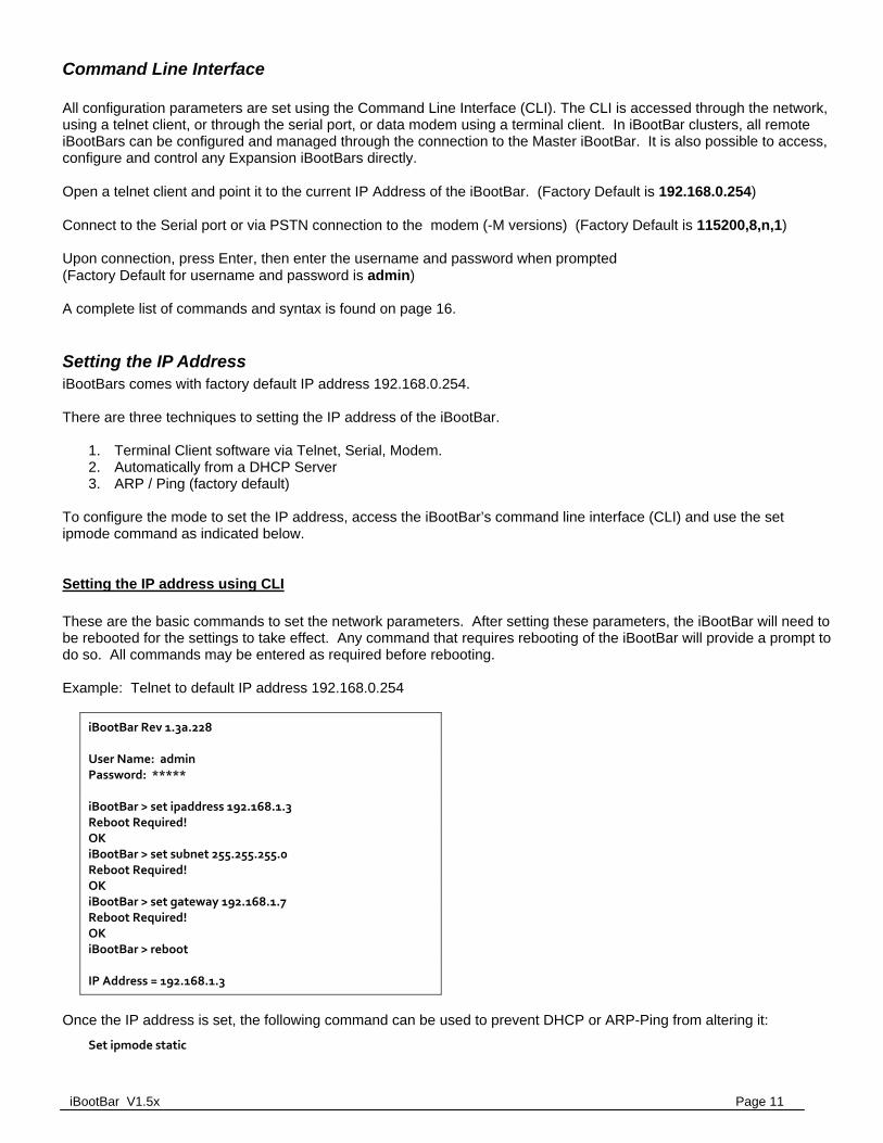
These are the basic commands to set the network parameters. After setting these parameters, the iBootBar will need to be rebooted for the settings to take effect. Any command that requires rebooting of the iBootBar will provide a prompt to do so. All commands may be entered as required before rebooting. Example: Telnet to default IP address 192.168.0.254
iBootBar Rev 1.3a.228 User Name: admin Password: ***** iBootBar > set ipaddress 192.168.1.3 Reboot Required! OK iBootBar > set subnet 255.255.255.0 Reboot Required! OK iBootBar > set gateway 192.168.1.7 Reboot Required! OK iBootBar > reboot IP Address = 192.168.1.3
Once the IP address is set, the following command can be used to prevent DHCP or ARP-Ping from altering it:
Set ipmode static

Page 12 iBootBar V1.5x
Setting the IP address from a DHCP Server A DHCP server will automatically assign an IP address (dynamic address) as well as Subnet Mask and Gateway to the iBootBar.
To enable this feature, configure the iBootBar with the command set ipmode dhcp
Then reboot the iBootBar, or enter the command reboot To find the IP address of the iBootBar you will need to query your DHCP server and locate the MAC address of the iBootBar in the DHCP server’s IP / MAC table. You can also access the CLI and use the get network command, or use the Discover provision of the iBootBar Setup and Control Utility.
Setting the IP address using ARP / Ping
The ARP / Ping technique uses a PC running a command line (DOS Window) to set the IP Address. To set the IP address using ARP, connect the iBootBar to your local network and apply power. The IP address to be assigned to iBootBar must be use the same subnet as the computer assigning the address. ARP does not work across routed or switched networks. To set the IP address using ARP, the hardware (MAC) address must be known. This address is located on the bottom of the unit. The syntax for the MAC address is: nn-nn-nn-nn-nn-nn
Windows (98 and Later)
1. Access the iBootBar CLI and enter the set ipmode arp‐ping command 2. On a PC, open a DOS window. (Run: Command) 3. Type the following command: arp -s <IP Address> <MAC Address> Where <IP Address> is the desired IP address (in dotted decimal) for the iBootBar and the <MAC address> is
the MAC Address of the iBootBar. The MAC Address of the iBootBar is located on the rear of the unit.
Example: arp -s 63.211.86.165 00-50-c2-05-01-c1 <enter> |new IP addr| |---MAC addr----|
4. Ping the iBootBar to program the IP address into the iBootBar. Type: ping <IP Address>
Note: If the ping command returns “host not responding” 4 times then the address has not been programmed properly. Check the IP or MAC Address for typographical errors. Repeat step 2. If the problem persists, contact the Dataprobe Tech Support.
5. Delete the entry from the ARP cache by typing: arp -d <IP Address> 6. Ping the iBootBar to confirm that it has been programmed. If the iBootBar fails to respond, repeat steps 2-4 above. If the problem persists, contact Dataprobe Tech
Support.
Unix, Linux, MAC and others
Consult your systems administrator for information on how to set an IP Address. The unit should be pinged after the IP Address has been set to confirm proper operation.
Other Configuration Settings All parameters are set using the CLI. See Page 16 for a complete list.
iBootBar V1.5x Page 13
Basic Operation
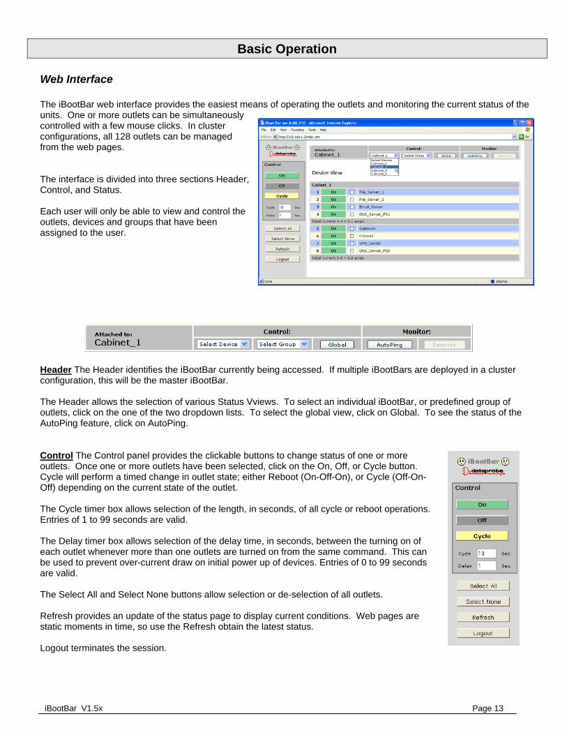
Web Interface The iBootBar web interface provides the easiest means of operating the outlets and monitoring the current status of the units. One or more outlets can be simultaneously controlled with a few mouse clicks. In cluster configurations, all 128 outlets can be managed from the web pages. The interface is divided into three sections Header, Control, and Status. Each user will only be able to view and control the outlets, devices and groups that have been assigned to the user.
Header The Header identifies the iBootBar currently being accessed. If multiple iBootBars are deployed in a cluster configuration, this will be the master iBootBar. The Header allows the selection of various Status Vviews. To select an individual iBootBar, or predefined group of outlets, click on the one of the two dropdown lists. To select the global view, click on Global. To see the status of the AutoPing feature, click on AutoPing. Control The Control panel provides the clickable buttons to change status of one or more outlets. Once one or more outlets have been selected, click on the On, Off, or Cycle button. Cycle will perform a timed change in outlet state; either Reboot (On-Off-On), or Cycle (Off-On-Off) depending on the current state of the outlet. The Cycle timer box allows selection of the length, in seconds, of all cycle or reboot operations. Entries of 1 to 99 seconds are valid. The Delay timer box allows selection of the delay time, in seconds, between the turning on of each outlet whenever more than one outlets are turned on from the same command. This can be used to prevent over-current draw on initial power up of devices. Entries of 0 to 99 seconds are valid. The Select All and Select None buttons allow selection or de-selection of all outlets. Refresh provides an update of the status page to display current conditions. Web pages are static moments in time, so use the Refresh obtain the latest status. Logout terminates the session.

Page 14 iBootBar V1.5x
Status The Status window displays the current view, controllable outlets, or other current information. Buttons in the Header select the current view.
Device View
The Device View displays the status of a single device. It shows the current status of each outlet of the device, and allows selection of one or more outlets for control. It also displays the current draw of each inlet and any alarms. Use the checkboxes to select or de-select any outlet for control. Outlet Status Outlet status is displayed by a colored text box. The color indicates the current status of the outlet and the text indicates the function being performed.
Inlet Status The current of each power inlet (main) is displayed below the outlets fed by that inlet. High current alarms are highlighted in red, low current alarms are highlighted in yellow.
Group View
The Group Veiw displays the status of a single group. Groups are two or more outlets linked together for simultaneous control. In the group view, each device containing a member of the group is displayed on a line, with the status of the outlets that are group members. Control the group by clicking on the appropriate button in the Control section.
Global View
The Global View displays all iBootBars in one view. Each outlet has a checkbox, allowing multiple outlets to be simultaneously controlled without the need to establish a group. Only outlets that the user has rights to will have status and control checkbox displayed.
On Outlet is On
Cycle Outlet is On during Cycle. It will turn off when cycle time is complete
Off Outlet is Off
Reboot Outlet is Off during Cycle. It will turn on when cycle time is complete
On / Pend Outlet is Off. It has been commanded to turn on and will do so in its turn based on the delay time.
Device View
Group View
Global View

iBootBar V1.5x Page 15
AutoPing View:
The AutoPing View displays the 16 AutoPing channels, their programmed action and current status. The status column will display the current status of the AutoPing. The numeric column will display the number of times the AutoPing has been triggered. A numeric counter other than 0, with the status reporting OK, indicates that there have been previous AutoPing triggers, but the current status is OK. To reset the trigger count, click on the Reset button. See Advanced Operation section page 26 for more about AutoPing
AutoPing View

Page 16 iBootBar V1.5x
Command Line Interface The Command Line Interface provides complete setup of all function of the iBootBar. Access the CLI either via the network interface using Telnet, or via the modem or serial port using a terminal emulation program. Some commands of the CLI require administrative rights. These are indicated in the table below.
Outlet Commands
Command Description Admin Fact Def
get outlets Returns the status of ALL the outlets the user has rights to. Displays all devices and outlets in a cluster configuration.
No
get outlet <1‐8> Returns the status of the iBootBar. This command is for iBootBars not used in a cluster configuration. If used in a cluster, it is the same as device #1. The user must have rights to the selected outlet.
No
set outlet <1‐8> <on/off/cycle> Sets the selected outlet to the selected state. The user must have rights to the selected outlet. This command is for iBootBars not used in a cluster configuration. If used in a cluster, it is the same as device #1
No
get device <#1‐#16/devname> outlet <1‐8> Returns the status of the select outlet on the selected iBootBar. Device is either the number of the device <#1 to #16> or the name of the device, as set. Number sign (#) required. The user must have rights to the selected outlet.
No
set device <#1‐#16/devname> outlet <1‐8> <on/off/cycle> Sets the selected outlet on the selected iBootBar to the selected state. The user must have rights to the selected outlet.
No
set device <#1‐#16/devname> outlet <1‐8> name <name> Sets the name of the selected outlet of the selected iBootBar. 20 characters max.
Yes Outlet <#>
get device <#1‐#16/devname> outlet <1‐8> initial.state Get or set the initial state of the selected outlet of the currently selected iBootBar. Initial state is the condition of the outlet when the iBootBar is powered up.
Yes Last
set device <#1‐#16/devname> outlet <1‐8> initial.state <on/off/last>

iBootBar V1.5x Page 17
User Commands
Command Description Admin Fact Def
get users Return a list of all current users Yes
get user <username> Returns the selected user’s details Yes
add user <username> Added a user to the root iBootBar’s user table. 16 users maximum. 20 Characters max. Note: the new user’s password will default to the same as the username. Users default to no rights to any outlets. Add user rights to outlets and groups.
Yes
del user <username> Deletes the selected user from the root iBootBar’s user table Yes
ren user <username> <newname> Renames the selected user in the root iBootBar’s user table. 20 character max.
Yes
set user <username> device <#1‐#16/devname/all> outlet <1‐8/all> <yes/no>
Sets the users right to the selected outlet on a specific device. Yes No Rights
set user <username> group <name> <yes/no> Sets the user’s rights to the selected group Yes No Rights
set user <username> role <admin/user> Sets the user’s roll. Yes User
set user <username> password <password> <confirm> Sets the user’s password. 20 characters max. Yes User’s Name
set user <username> email <address> Sets the user’s email address for the root iBootBar to send alerts to. 64 characters max.
yes
set user <username> sendmail <yes/no> Enables or disables the user’s receipt of email alerts. Yes No
set set user <username> pin <pin> Sets the user PIN for DTMF control. –M models only. 4 – 10 digits. Yes
Page 18 iBootBar V1.5x
Device Commands
Command Description Admin Fact Default
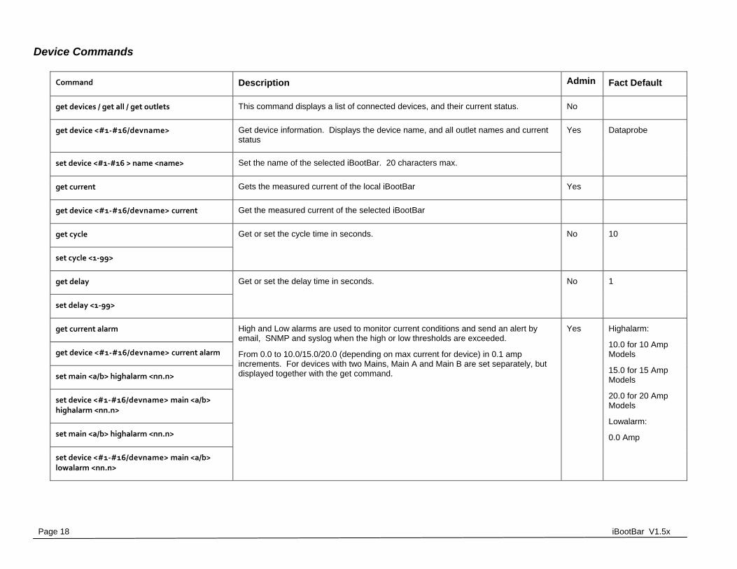
get devices / get all / get outlets This command displays a list of connected devices, and their current status. No
get device <#1‐#16/devname> Get device information. Displays the device name, and all outlet names and current status
Yes Dataprobe
set device <#1‐#16 > name <name> Set the name of the selected iBootBar. 20 characters max.
get current Gets the measured current of the local iBootBar Yes
get device <#1‐#16/devname> current Get the measured current of the selected iBootBar
get cycle Get or set the cycle time in seconds. No 10
set cycle <1‐99>
get delay Get or set the delay time in seconds. No 1
set delay <1‐99>
get current alarm High and Low alarms are used to monitor current conditions and send an alert by email, SNMP and syslog when the high or low thresholds are exceeded.
From 0.0 to 10.0/15.0/20.0 (depending on max current for device) in 0.1 amp increments. For devices with two Mains, Main A and Main B are set separately, but displayed together with the get command.
Yes Highalarm:
10.0 for 10 Amp Models
15.0 for 15 Amp Models
20.0 for 20 Amp Models
Lowalarm:
0.0 Amp
get device <#1‐#16/devname> current alarm
set main <a/b> highalarm <nn.n>
set device <#1‐#16/devname> main <a/b> highalarm <nn.n>
set main <a/b> highalarm <nn.n>
set device <#1‐#16/devname> main <a/b> lowalarm <nn.n>
iBootBar V1.5x Page 19
get console Displays the current console configuration, Timeout and Baud Rate Yes
set console timeout <30‐3600/disable> Console can be set to automatically logout with no activity for 30 seconds to 1 hr in seconds, or disabled.
Yes 120
set console baudrate <400/4800/9600/19200/38400/ 57600/115200>
The baud rate of the serial port. 400,4800,9600,19200 ,38400,57600,115200 bps Yes 115200
get modem Gets the current settings of the modem. –M models only. Yes
set modem countrycode <contrycode> Sets the modem country code. –M models only.
See page 34 for a list of country codes.
Yes 181 (USA)
set device <0‐16> Get / Set the device ID for cluster applications. A device ID of 0 for single iBootBar applications. A device ID of 1 makes the unit a master, and a device ID of 2-16 make the iBB a remote in cluster configurations. These commands are only valid when directly connected to the iBootBar, rather than as remote units in a cluster.
Yes 0
get device
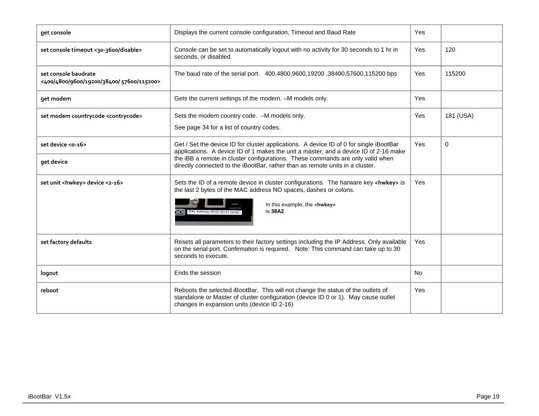
set unit <hwkey> device <2‐16> Sets the ID of a remote device in cluster configurations. The harware key <hwkey> is the last 2 bytes of the MAC address NO spaces, dashes or colons.
Yes
set factory defaults Resets all parameters to their factory settings including the IP Address. Only available on the serial port. Confirmation is required. Note: This command can take up to 30 seconds to execute.
Yes
logout Ends the session No
reboot Reboots the selected iBootBar. This will not change the status of the outlets of standalone or Master of cluster configuration (device ID 0 or 1). May cause outlet changes in expansion units (device ID 2-16)
Yes
In this example, the <hwkey> is 38A2
Page 20 iBootBar V1.5x
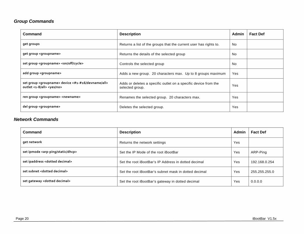
Group Commands
Command Description Admin Fact Def
get groups Returns a list of the groups that the current user has rights to. No
get group <groupname> Returns the details of the selected group No
set group <groupname> <on/off/cycle> Controls the selected group No
add group <groupname> Adds a new group. 20 characters max. Up to 8 groups maximum Yes
set group <groupname> device <#1‐#16/devname/all> outlet <1‐8/all> <yes/no>
Adds or deletes a specific outlet on a specific device from the selected group.
Yes
ren group <groupname> <newname> Renames the selected group. 20 characters max. Yes
del group <groupname> Deletes the selected group. Yes
Network Commands
Command Description Admin Fact Def
get network Returns the network settings Yes
set ipmode <arp‐ping/static/dhcp> Set the IP Mode of the root iBootBar Yes ARP-Ping
set ipaddress <dotted decimal> Set the root iBootBar’s IP Address in dotted decimal Yes 192.168.0.254
set subnet <dotted decimal> Set the root iBootBar’s subnet mask in dotted decimal Yes 255.255.255.0
set gateway <dotted decimal> Set the root iBootBar’s gateway in dotted decimal Yes 0.0.0.0
iBootBar V1.5x Page 21
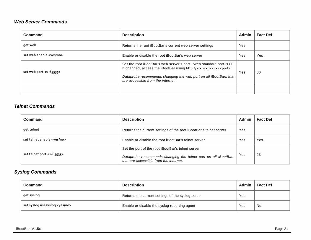
Web Server Commands
Command Description Admin Fact Def
get web Returns the root iBootBar’s current web server settings Yes
set web enable <yes/no> Enable or disable the root iBootBar’s web server Yes Yes
set web port <1‐65535>
Set the root iBootBar’s web server’s port. Web standard port is 80. If changed, access the iBootBar using http://xxx.xxx.xxx.xxx:<port> Dataprobe recommends changing the web port on all iBootBars that are accessible from the internet.
Yes 80
set web ssl <yes/no> Enable or disable the root iBootBars web server’s SSL capabilities. Yes No
Telnet Commands
Command Description Admin Fact Def
get telnet Returns the current settings of the root iBootBar’s telnet server. Yes
set telnet enable <yes/no> Enable or disable the root iBootBar’s telnet server Yes Yes
set telnet port <1‐65535>
Set the port of the root iBootBar’s telnet server. Dataprobe recommends changing the telnet port on all iBootBars that are accessible from the internet.
Yes 23
Syslog Commands
Command Description Admin Fact Def
get syslog Returns the current settings of the syslog setup Yes
set syslog usesyslog <yes/no> Enable or disable the syslog reporting agent Yes No

Page 22 iBootBar V1.5x
Command Description Admin Fact Def
set syslog server Set the IP address of the syslog server. Yes
Autoping Commands
Command Description Admin Fact Def
get autoping <1‐16> Returns the settings and state of the selected autoping. Yes
set autoping <1‐16> ipaddress <dotted decimal> Set the IP address of the selected auto ping in dotted decimal. Yes 0.0.0.0
set autoping <1‐16> action <action> Set the action of the selected auto ping. On-Follow, On-Latch, Off-Follow, Off-Latch, Cycle, Cycle-Once, or None.
Yes None
set autoping <1‐16> frequency <1‐999> Set the frequency of the selected autoping in seconds Yes 10
set autoping <1‐16> count <1‐99> Set the number of failures the select autoping requires before it triggers its action.
Yes 3
set autoping <1‐16> device <name/#1‐16>
outlet <1‐8>
Assign an AutoPing to either a device/outlet or group. Each AutoPing can be assigned to one or the other
Yes
set autoping <1‐16> group <name> Yes
Event Commands
Command Description Admin Fact Def
get events Returns a list of all pending events Yes
get event <eventname> Returns the details of the selected event Yes
add event <eventname> Creates a new event. Up to 16 events can be created. The default time and date will be the time and date that the event is
Yes
iBootBar V1.5x Page 23
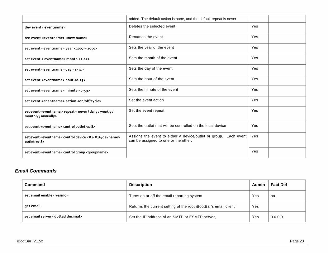
added. The default action is none, and the default repeat is never
dev event <eventname> Deletes the selected event Yes
ren event <eventname> <new name> Renames the event. Yes
set event <eventname> year <2007 – 2050> Sets the year of the event Yes
set event < eventname> month <1‐12> Sets the month of the event Yes
set event <eventname> day <1‐31> Sets the day of the event Yes
set event <eventname> hour <0‐23> Sets the hour of the event. Yes
set event <eventname> minute <0‐59> Sets the minute of the event Yes
set event <enentname> action <on/off/cycle> Set the event action Yes
set event <eventname > repeat < never / daily / weekly / monthly / annually>
Set the event repeat Yes
set event <eventname> control outlet <1‐8> Sets the outlet that will be controlled on the local device Yes
set event <eventname> control device <#1‐#16/devname> outlet <1‐8>
Assigns the event to either a device/outlet or group. Each event can be assigned to one or the other.
Yes
set event <eventname> control group <groupname> Yes
Email Commands
Command Description Admin Fact Def
set email enable <yes/no> Turns on or off the email reporting system Yes no
get email Returns the current setting of the root iBootBar’s email client Yes
set email server <dotted decimal> Set the IP address of an SMTP or ESMTP server, Yes 0.0.0.0

Page 24 iBootBar V1.5x
Command Description Admin Fact Def
set email address <return address> Set the return address of the root iBootBar’s email client. Yes 0.0.0.0
set email username <username> Set the user name for the mail server Yes 0.0.0.0
set email password <password> Set the password for the mail server Yes 0.0.0.0
set email retries <1‐999> Set the number of retries for failed email reporting Yes 3
send test mail <username> Send a test email to user Yes
Time Commands
Command Description Admin Fact Def
get time Returns the current time and NTS settings Yes
set time server <ip address> Sets the address of a NTS server for the root iBootBar to query. Yes 129.6.15.29
set time usents <yes/no> Enables or disables the root iBootBar’s ability to connect to an NTS Yes Yes
set time zone <‐12 to 12> Set the time zone the root iBootBar is in. Yes -4
set time hour <0‐23> Sets the hour of the root iBootBar’s RTC. Only valid if NTS is disabled.
Yes
set time minute <0‐59> Sets the minute of the root iBootBar’s RTC. Only valid if NTS is disabled.
Yes
set time day <1‐31> Sets the day of the root iBootBar’s RTC. Only valid if NTS is disabled.
Yes
set time month <1‐12> Sets the month of the root iBootBar’s RTC. Only valid if NTS is disabled.
Yes
set time year <2006‐20047> Sets the year of the root iBootBar’s RTC. Only valid if NTS is disabled.
Yes

iBootBar V1.5x Page 25
Firmware Upload Commands
Command Description Admin Fact Def
get upload enable Get or set the ability for the root iBootBar to accept a firmware upload.
Yes
set upload enable Yes No

Page 26 iBootBar V1.5x
Advanced Operation
DTMF Control Models with an internal modem <-M suffix> can be controlled from dial up connections using handset dialing tones (touch tones). Use of DTMF control requires a unique PIN number set for each user. This PIN is set using the command line interface and must be 4 to 10 digits long. Program a PIN code of 0 to disable a users ability to use DTMF control.
DTMF Call Sequence:
1. Dial the phone number connected to the iBootBar. Upon connection a prompt tone will be heard.
2. Enter the PIN followed by the # key. Upon successful entry, a ready tone will be heard. If no PIN or incorrect PIN is received, an error tone and new prompt tone will be issued. After three unsuccessful attempts, the iBootBar will hang up.
3. At the ready tone, enter an outlet number 1-8. The current status of that outlet will be stated in English: i.e. “one on” or “six off”.
4. The # key is used to change the state of the outlet. The * key is used to reboot (or power cycle) the outlet for the time configured with the CLI command cycle time. The new status of the outlet is stated. If the * key is used, the iBootBar will also state ‘begin’ to indicate the reboot or cycle has begun.
5. A new prompt tone will indicate that new commands can be entered. While a reboot is in progress, additional outlets can be addressed and commanded.
6. The caller can hang up at any time to disconnect the call. Any reboots in progress will finish their cycle time as programmed.
NOTE: Not issuing a command for 5 seconds will cause the iBootBar to hang up.
Notes:
1. The only outlets that a caller has access to are determined by the CLI command set user outlet.
2. While prompts and voice responses are being played, the iBootBar will not process DTMF tones. Wait for the status and prompts to complete before issuing new commands
3. Address an outlet with a number command before entering a control command (# or *) if unsure which outlet is being addressed, send the outlet number again.
4. Factory Default user admin has default PIN 23646. Change to desired PIN if maintaining this account. Resetting to factory defaults will restore this user and PIN.

iBootBar V1.5x Page 27
Timed Events The iBootBar provides the ability to turn On, Off or Cycle outlets based on time and date. Each individual outlet or group can be set to operate a selected command at a specific time and date. The Timed Events are programmed thru the Control & Setup Utility or the CLI interface. Up to 16 events can be created. Each event can be assigned to one outlet or group and repeated on a regular basis. Administrative rights are required to set up and manage any event. To add an event, create the event, assign the event to a specific outlet or group and then configure the initial occurrence of the event, the action to be performed, and the repeat frequency, if desired. To configure the timed events, use the following commands: get events
get event <eventname>
add event <eventname>
dev event <eventname>
ren event <eventname> <new name>
set event <eventname> year <2007 – 2050>
set event < eventname> month <1‐12>
set event <eventname> day <1‐31>
set event <eventname> hour <0‐23>
set event <eventname> minute <0‐59>
set event <enentname> action <on/off/cycle>
set event <eventname > repeat < never / daily / weekly / monthly / annually>
set event <eventname> control outlet <1‐8>
set event <eventname> control device <#1‐#16/devname> outlet <1‐8>
set event <eventname> control group <groupname>
Page 28 iBootBar V1.5x
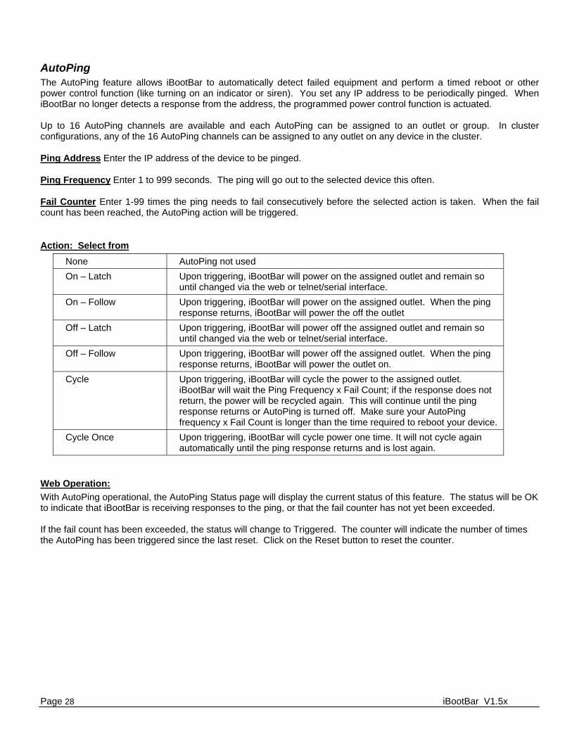
AutoPing The AutoPing feature allows iBootBar to automatically detect failed equipment and perform a timed reboot or other power control function (like turning on an indicator or siren). You set any IP address to be periodically pinged. When iBootBar no longer detects a response from the address, the programmed power control function is actuated. Up to 16 AutoPing channels are available and each AutoPing can be assigned to an outlet or group. In cluster configurations, any of the 16 AutoPing channels can be assigned to any outlet on any device in the cluster. Ping Address Enter the IP address of the device to be pinged. Ping Frequency Enter 1 to 999 seconds. The ping will go out to the selected device this often. Fail Counter Enter 1-99 times the ping needs to fail consecutively before the selected action is taken. When the fail count has been reached, the AutoPing action will be triggered.
Action: Select from
None AutoPing not used
On – Latch Upon triggering, iBootBar will power on the assigned outlet and remain so until changed via the web or telnet/serial interface.
On – Follow Upon triggering, iBootBar will power on the assigned outlet. When the ping response returns, iBootBar will power the off the outlet
Off – Latch Upon triggering, iBootBar will power off the assigned outlet and remain so until changed via the web or telnet/serial interface.
Off – Follow Upon triggering, iBootBar will power off the assigned outlet. When the ping response returns, iBootBar will power the outlet on.
Cycle Upon triggering, iBootBar will cycle the power to the assigned outlet. iBootBar will wait the Ping Frequency x Fail Count; if the response does not return, the power will be recycled again. This will continue until the ping response returns or AutoPing is turned off. Make sure your AutoPing frequency x Fail Count is longer than the time required to reboot your device.
Cycle Once Upon triggering, iBootBar will cycle power one time. It will not cycle again automatically until the ping response returns and is lost again.
Web Operation:
With AutoPing operational, the AutoPing Status page will display the current status of this feature. The status will be OK to indicate that iBootBar is receiving responses to the ping, or that the fail counter has not yet been exceeded. If the fail count has been exceeded, the status will change to Triggered. The counter will indicate the number of times the AutoPing has been triggered since the last reset. Click on the Reset button to reset the counter.
iBootBar V1.5x Page 29
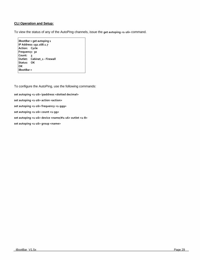
CLI Operation and Setup:
To view the status of any of the AutoPing channels, issue the get autoping <1‐16> command.
iBootBar > get autoping 1 IP Address: 192.168.1.7 Action: Cycle Frequency: 30 Count: 3 Outlet: Cabinet_1 ‐ Firewall Status: OK OK iBootBar >
To configure the AutoPing, use the following commands: set autoping <1‐16> ipaddress <dotted decimal>
set autoping <1‐16> action <action>
set autoping <1‐16> frequency <1‐999>
set autoping <1‐16> count <1‐99>
set autoping <1‐16> device <name/#1‐16> outlet <1‐8>
set autoping <1‐16> group <name>
Page 30 iBootBar V1.5x
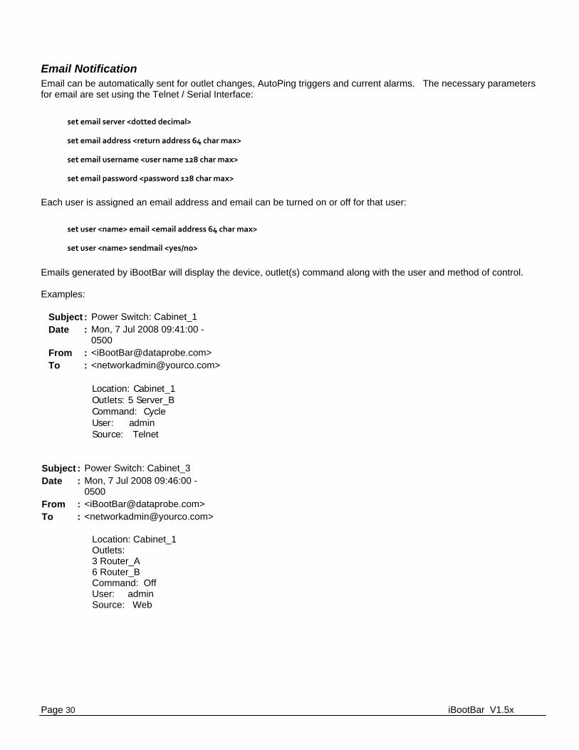
Email Notification Email can be automatically sent for outlet changes, AutoPing triggers and current alarms. The necessary parameters for email are set using the Telnet / Serial Interface:
set email server <dotted decimal>
set email address <return address 64 char max>
set email username <user name 128 char max>
set email password <password 128 char max>
Each user is assigned an email address and email can be turned on or off for that user:
set user <name> email <email address 64 char max>
set user <name> sendmail <yes/no>
Emails generated by iBootBar will display the device, outlet(s) command along with the user and method of control. Examples:
Subject : Power Switch: Cabinet_1 Date : Mon, 7 Jul 2008 09:41:00 -
0500 From : <[email protected]> To : <[email protected]>
Location: Cabinet_1 Outlets: 5 Server_B Command: Cycle User: admin Source: Telnet
Subject : Power Switch: Cabinet_3 Date : Mon, 7 Jul 2008 09:46:00 -
0500 From : <[email protected]> To : <[email protected]>
Location: Cabinet_1 Outlets: 3 Router_A 6 Router_B Command: Off User: admin Source: Web
iBootBar V1.5x Page 31
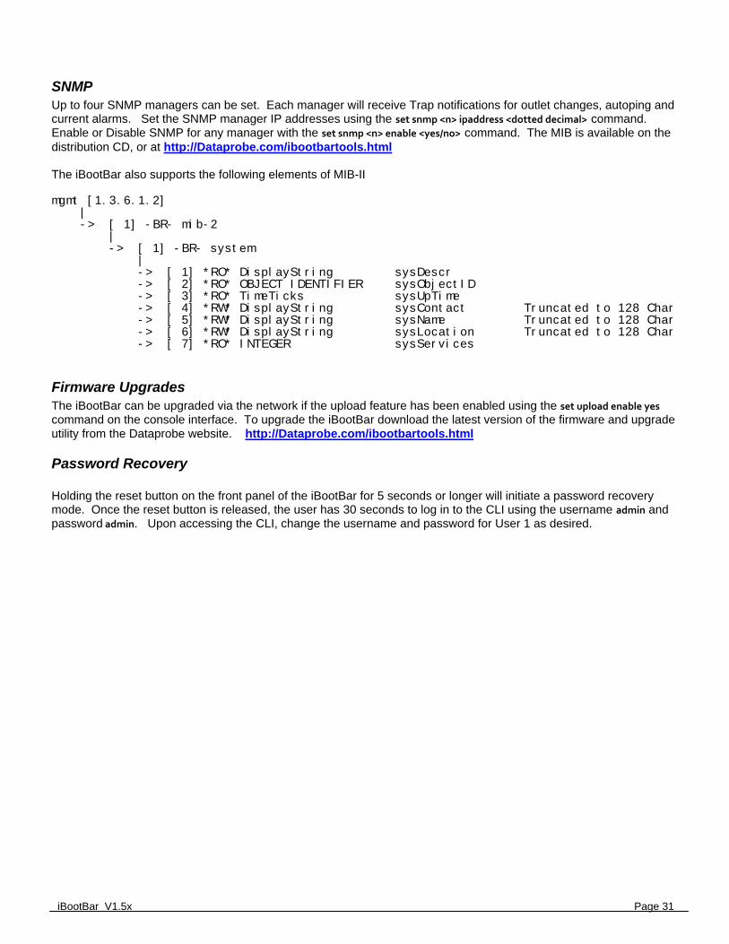
SNMP Up to four SNMP managers can be set. Each manager will receive Trap notifications for outlet changes, autoping and current alarms. Set the SNMP manager IP addresses using the set snmp <n> ipaddress <dotted decimal> command. Enable or Disable SNMP for any manager with the set snmp <n> enable <yes/no> command. The MIB is available on the distribution CD, or at http://Dataprobe.com/ibootbartools.html The iBootBar also supports the following elements of MIB-II mgmt [1.3.6.1.2] | -> [ 1] -BR- mib-2 | -> [ 1] -BR- system | -> [ 1] *RO* DisplayString sysDescr -> [ 2] *RO* OBJECT IDENTIFIER sysObjectID -> [ 3] *RO* TimeTicks sysUpTime -> [ 4] *RW* DisplayString sysContact Truncated to 128 Char -> [ 5] *RW* DisplayString sysName Truncated to 128 Char -> [ 6] *RW* DisplayString sysLocation Truncated to 128 Char -> [ 7] *RO* INTEGER sysServices
Firmware Upgrades The iBootBar can be upgraded via the network if the upload feature has been enabled using the set upload enable yes command on the console interface. To upgrade the iBootBar download the latest version of the firmware and upgrade utility from the Dataprobe website. http://Dataprobe.com/ibootbartools.html
Password Recovery Holding the reset button on the front panel of the iBootBar for 5 seconds or longer will initiate a password recovery mode. Once the reset button is released, the user has 30 seconds to log in to the CLI using the username admin and password admin. Upon accessing the CLI, change the username and password for User 1 as desired.
Page 32 iBootBar V1.5x
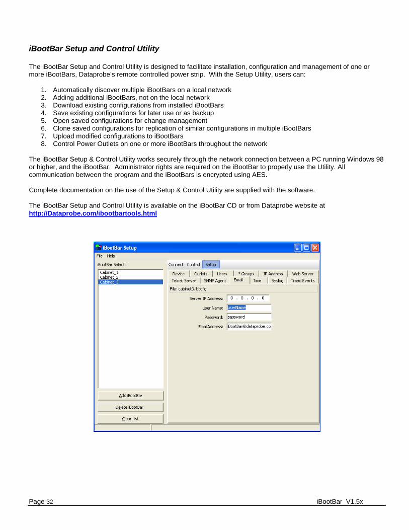
iBootBar Setup and Control Utility The iBootBar Setup and Control Utility is designed to facilitate installation, configuration and management of one or more iBootBars, Dataprobe’s remote controlled power strip. With the Setup Utility, users can:
1. Automatically discover multiple iBootBars on a local network 2. Adding additional iBootBars, not on the local network 3. Download existing configurations from installed iBootBars 4. Save existing configurations for later use or as backup 5. Open saved configurations for change management 6. Clone saved configurations for replication of similar configurations in multiple iBootBars 7. Upload modified configurations to iBootBars 8. Control Power Outlets on one or more iBootBars throughout the network
The iBootBar Setup & Control Utility works securely through the network connection between a PC running Windows 98 or higher, and the iBootBar. Administrator rights are required on the iBootBar to properly use the Utility. All communication between the program and the iBootBars is encrypted using AES. Complete documentation on the use of the Setup & Control Utility are supplied with the software. The iBootBar Setup and Control Utility is available on the iBootBar CD or from Dataprobe website at http://Dataprobe.com/ibootbartools.html
iBootBar V1.5x Page 33
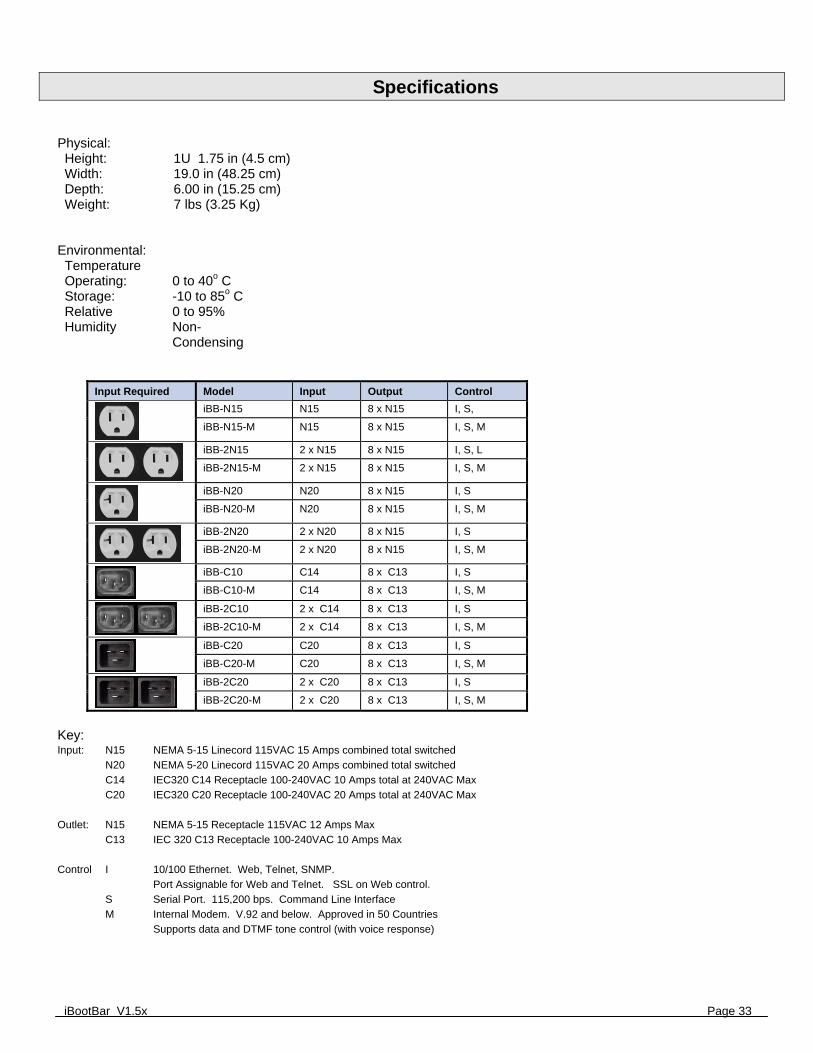
Specifications Physical: Height: 1U 1.75 in (4.5 cm) Width: 19.0 in (48.25 cm) Depth: 6.00 in (15.25 cm) Weight: 7 lbs (3.25 Kg)
Environmental: Temperature Operating: 0 to 40o C Storage: -10 to 85o C Relative Humidity
0 to 95% Non-Condensing
Input Required Model Input Output Control
iBB-N15 N15 8 x N15 I, S,
iBB-N15-M N15 8 x N15 I, S, M
iBB-2N15 2 x N15 8 x N15 I, S, L
iBB-2N15-M 2 x N15 8 x N15 I, S, M
iBB-N20 N20 8 x N15 I, S
iBB-N20-M N20 8 x N15 I, S, M
iBB-2N20 2 x N20 8 x N15 I, S
iBB-2N20-M 2 x N20 8 x N15 I, S, M
iBB-C10 C14 8 x C13 I, S
iBB-C10-M C14 8 x C13 I, S, M
iBB-2C10 2 x C14 8 x C13 I, S
iBB-2C10-M 2 x C14 8 x C13 I, S, M
iBB-C20 C20 8 x C13 I, S
iBB-C20-M C20 8 x C13 I, S, M
iBB-2C20 2 x C20 8 x C13 I, S
iBB-2C20-M 2 x C20 8 x C13 I, S, M
Key: Input: N15 NEMA 5-15 Linecord 115VAC 15 Amps combined total switched
N20 NEMA 5-20 Linecord 115VAC 20 Amps combined total switched
C14 IEC320 C14 Receptacle 100-240VAC 10 Amps total at 240VAC Max
C20 IEC320 C20 Receptacle 100-240VAC 20 Amps total at 240VAC Max
Outlet: N15 NEMA 5-15 Receptacle 115VAC 12 Amps Max
C13 IEC 320 C13 Receptacle 100-240VAC 10 Amps Max
Control I 10/100 Ethernet. Web, Telnet, SNMP.
Port Assignable for Web and Telnet. SSL on Web control.
S Serial Port. 115,200 bps. Command Line Interface
M Internal Modem. V.92 and below. Approved in 50 Countries
Supports data and DTMF tone control (with voice response)

Page 34 iBootBar V1.5x
Compliance Statements
FCC Part 15 Regulation This equipment has been tested and found to comply with the limits for a Class A digital device, pursuant to Part 15 of the FCC rules. These limits are designed to provide reasonable protection against harmful interference in a residential installation. This equipment generates, uses, and can radiate radio frequency energy, and if not installed and used in accordance with the instructions, may cause harmful interference to radio communications. However, there is no guarantee that interference will not occur in a particular installation. If this equipment does cause harmful interference to radio or television reception, which can be determined by turning the equipment off and on, the user is encouraged to try to correct the interference by one or more of the following measures:
• Reorient or relocate the receiving antenna. • Increase the separation between the equipment and receiver. • Plug the equipment into an outlet on a circuit that is different from the one used by the receiver. • Consult the dealer or an experienced radio/TV technician for help.
This device complies with Part 15 of the FCC rules. Operation of this device is subject to the following conditions: (1) This device may not cause harmful interference, and (2) this device must accept any interference that may cause undesired operation. WARNING: Changes or modifications to this unit not expressly approved by the party responsible for compliance could void the user’s authority to operate the equipment
EMC, Safety, and R&TTE Directive Compliance The CE mark is affixed to this product to confirm compliance with the following European Community Directives: • Council Directive 89/336/EEC of 3 May 1989 on the approximation of the laws of Member States relating to electromagnetic compatibility; And • Council Directive 73/23/EEC of 19 February 1973 on the harmonization of the laws of Member States relating to electrical equipment designed for use within certain voltage limits; and • Council Directive 1999/5/EC of 9 March on radio equipment and telecommunications terminal equipment and the mutual recognition of their conformity.
Industry Canada This Class A digital apparatus meets all requirements of the Canadian Interference-Causing Equipment Regulations. Cet appareil numérique de la classe AB respecte toutes les exigences du Reglement Canadien sur le matériel brouilleur. This product meets the applicable Industry Canada technical specifications

iBootBar V1.5x Page 35
Modem Certifications The following countries have certified the internal modem. In order to comply with local regulations, the countrycode must be set to the country of installation. To set the modem for the desired country use the CLI command set modem
countrycode <countrycode>. Use the get modem command to display the current country setting. Note: Use of the wrong countrycode violates local laws and the warranty of this product. Country countrycode Country countrycode Argentina 07 Latvia 253 Australia 09 Liechtenstein 253 Austria 253 Lithuania 253 Belgium 253 Luxembourg 253 Brazil 22 Malaysia 108 Bulgaria 253 Malta 253 Canada 181 Mexico 181 Chile 153 Netherlands 253 China 181 New Zealand 126 Cyprus 253 Norway 253 Czech Republic 253 Philippines 181 Denmark 253 Poland 253 Estonia 253 Portugal 253 Finland 253 Russia 253 France 253 Singapore 156 Germany 253 Slovak Republic 253 Greece 253 Slovenia 253 Hong Kong 153 South Africa 159 Hungary 253 Spain 253 Iceland 253 Sweden 253 India 153 Switzerland 253 Indonesia 153 Taiwan 254 Ireland 253 Thailand 181 Israel 181 Turkey 253 Italy 253 United Kingdom 253 Japan 00 United States 181 Korea 181
Page 36 iBootBar V1.5x
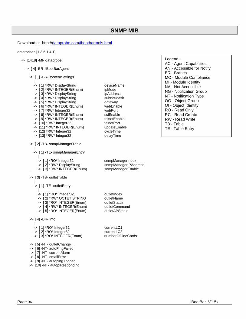
SNMP MIB Download at http://dataprobe.com/ibootbartools.html enterprises [1.3.6.1.4.1] | -> [1418] -MI- dataprobe | -> [ 4] -BR- iBootBarAgent | -> [ 1] -BR- systemSettings | -> [ 1] *RW* DisplayString deviceName -> [ 2] *RW* INTEGER(Enum) ipMode -> [ 3] *RW* DisplayString ipAddress -> [ 4] *RW* DisplayString subnetMask -> [ 5] *RW* DisplayString gateway -> [ 6] *RW* INTEGER(Enum) webEnable -> [ 7] *RW* Integer32 webPort -> [ 8] *RW* INTEGER(Enum) sslEnable -> [ 9] *RW* INTEGER(Enum) telnetEnable -> [10] *RW* Integer32 telnetPort -> [11] *RW* INTEGER(Enum) updateEnable -> [12] *RW* Integer32 cycleTime -> [13] *RW* Integer32 delayTime | -> [ 2] -TB- snmpManagerTable | -> [ 1] -TE- snmpManagerEntry | -> [ 1] *RO* Integer32 snmpManagerIndex -> [ 2] *RW* DisplayString snmpManagerIPAddress -> [ 3] *RW* INTEGER(Enum) snmpManagerEnable | -> [ 3] -TB- outletTable | -> [ 1] -TE- outletEntry | -> [ 1] *RO* Integer32 outletIndex -> [ 2] *RW* OCTET STRING outletName -> [ 3] *RO* INTEGER(Enum) outletStatus -> [ 4] *RW* INTEGER(Enum) outletCommand -> [ 5] *RO* INTEGER(Enum) outletAPStatus | -> [ 4] -BR- info | -> [ 1] *RO* Integer32 currentLC1 -> [ 2] *RO* Integer32 currentLC2 -> [ 3] *RO* INTEGER(Enum) numberOfLineCords | -> [ 5] -NT- outletChange -> [ 6] -NT- autoPingFailed -> [ 7] -NT- currentAlarm -> [ 8] -NT- emailError -> [ 9] -NT- autopingTrigger -> [10] -NT- autopiResponding
Legend : AC - Agent Capabilities AN - Accessible for Notify BR - Branch MC - Module Compliance MI - Module Identity NA - Not Accessible NG - Notification Group NT - Notification Type OG - Object Group OI - Object Identity RO - Read Only RC - Read Create RW - Read Write TB - Table TE - Table Entry

Seller warrants this product, if used in accordance with all applicable instructions, to be free from
original defects in material and workmanship for a period of Three Years from the date of initial
purchase. If the product should prove defective within that period, Seller will repair or replace the
product, at its sole discretion. Repairs may be made with new or refurbished components and
replacements may be new or refurbished at the Sellers sole discretion. Repaired or replaced units shall
be warranteed for the balance of the original warranty, or 90 days, whichever is greater.
If Purchased from Dataprobe Inc.; Service under this Warranty is obtained by shipping the product (with
all charges prepaid) to the address below. Seller will pay return shipping charges within the United
States. Call Dataprobe Technical Service to receive a Return Materials Authorization (RMA) Number
prior to sending any equipment back for repair. Include all cables, power supplies, accessories and proof
of purchase with shipment.
If purchased from an Authorized Dataprobe Reseller; Service under this Warranty is obtained by
contacting your Authorized Dataprobe Reseller.
THIS WARRANTY DOES NOT APPLY TO NORMAL WEAR OR TO DAMAGE RESULTING FROM ACCIDENT,
MISUSE, ABUSE OR NEGLECT. SELLER MAKES NO EXPRESS WARRANTIES OTHER THAN THE
WARRANTY EXPRESSLY SET FORTH HEREIN. EXCEPT TO THE EXTENT PROHIBITED BY LAW, ALL
IMPLIED WARRANTIES, INCLUDING ALL WARRANTIES OF MERCHANT ABILITY OR FITNESS FOR ANY
PURPOSE ARE LIMITED TO THE WARRANTY PERIOD SET FORTH ABOVE; AND THIS WARRANTY
EXPRESSLY EXCLUDES ALL INCIDENTAL AND CONSEQUENTIAL DAMAGES.
Some states do not allow limitations on how long an implied warranty lasts, and some states do not
allow the exclusion or limitation of incidental or consequential damages, so the above limitations or
exclusions may not apply to you. This warranty gives you specific legal rights, and you may have other
rights which vary from jurisdictions to jurisdiction.
WARNING: The individual user should take care to determine prior to use whether this device is
suitable, adequate or safe for the use intended. Since individual applications are subject to great
variation, the manufacturer makes no representation or warranty as to the suitability of fitness for any
specific application.
Dataprobe Inc.
Technical Support: 201-934-5111
www.dataprobe.com/support.html
WARRANTY