SCOPE OF SPECIFICATIONS · ICAO Annex 10 Vol. I Aeronautical Telecommunications : Volume I Radio...
51
Project Name Date DME for PRACHINBURI Station, SUKHOTHAI Airport June 30, 2017 and TAK Airport Version 2.0 Scope of Specifications SCOPE OF SPECIFICATIONS 1. TECHNICAL SPECIFICATIONS 2. CIVIL WORK
Transcript of SCOPE OF SPECIFICATIONS · ICAO Annex 10 Vol. I Aeronautical Telecommunications : Volume I Radio...

Project Name Date
DME for PRACHINBURI Station, SUKHOTHAI Airport June 30, 2017
and TAK Airport Version 2.0
Scope of Specifications
SCOPE OF SPECIFICATIONS
1. TECHNICAL SPECIFICATIONS 2. CIVIL WORK
Project Name Date
DME for PRACHINBURI Station, SUKHOTHAI Airport June 30, 2017
and TAK Airport Version 2.0
Scope of Specifications
TABLE OF CONTENTS
TOR OF DME/DME SYSTEM FOR SUPPORTING PBN (DME RNAV) OPERATION
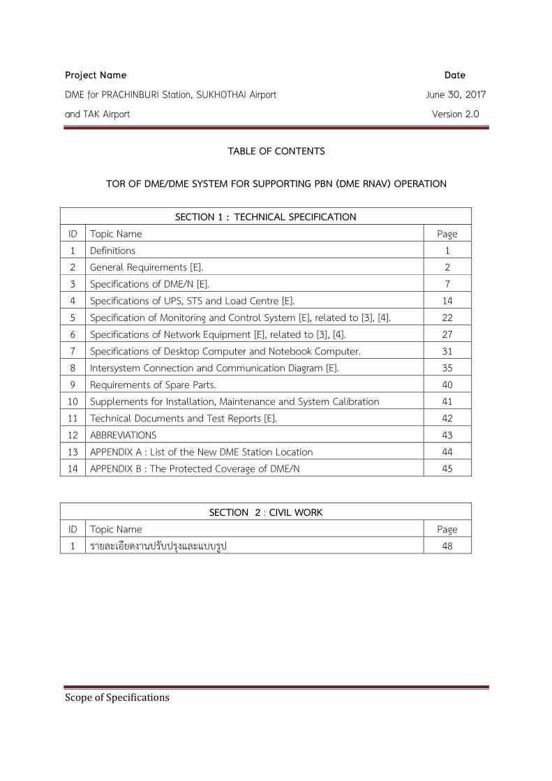
SECTION 1 : TECHNICAL SPECIFICATION ID Topic Name Page 1 Definitions 1 2 General Requirements [E]. 2 3 Specifications of DME/N [E]. 7 4 Specifications of UPS, STS and Load Centre [E]. 14 5 Specification of Monitoring and Control System [E], related to [3], [4]. 22 6 Specifications of Network Equipment [E], related to [3], [4]. 27 7 Specifications of Desktop Computer and Notebook Computer. 31 8 Intersystem Connection and Communication Diagram [E]. 35 9 Requirements of Spare Parts. 40 10 Supplements for Installation, Maintenance and System Calibration 41 11 Technical Documents and Test Reports [E]. 42 12 ABBREVIATIONS 43 13 APPENDIX A : List of the New DME Station Location 44 14 APPENDIX B : The Protected Coverage of DME/N 45
SECTION 2 : CIVIL WORK
ID Topic Name Page 1 รายละเอยดงานปรบปรงและแบบรป 48

Project Name Date
DME for PRACHINBURI Station, SUKHOTHAI Airport June 30, 2017
and TAK Airport Version 2.0
Scope of Specifications
SECTION 1
TECHNICAL SPECIFICATIONS

Project Name Date
DME for PRACHINBURI Station, SUKHOTHAI Airport June 30, 2017
and TAK Airport Version 2.0
Scope of Specifications Page 1
1. Definitions
In the specification, the following words and expression shall have the meanings assigned to them here under except where the context otherwise requires :
AEROTHAI Aeronautical Radio of Thailand Ltd.
Tenderer The juristic person, firm or company who offers to provide materials or perform a service or do a job with AEROTHAI at a specified cost or rate.
Contractor The juristic person, firm or company whose tender(s) /proposal(s) has /have been accepted by AEROTHAI and who agrees to accomplish the activities for AEROTHAI.
Proposal The response to the requirement specified in Scope of Specifications.
Essential requirement specification [E]
Essential requirement specification which is mandatory requirement by which the tenderer shall fully comply with AEROTHAI's requirement stipulated in Scope of Specifications. The Proposal will be rejected if the proposed system, functions of features fail to comply with Essential requirement specification.
ICAO Annex 10 Vol. I Aeronautical Telecommunications : Volume I Radio Navigation Aids. Sixth Edition, July 2006, Amendments 89
ICAO Doc 8071 Vol. I Manual on Testing of Radio Navigation Aids: Volume I Testing of Ground-Based Radio Navigation Systems. Fourth Edition – 2000, Amendments 1
ICAO Annex 14 Vol. I Aerodromes : Volume I Aerodrome Design and Operations. Sixth Edition, July 2013, Amendments 11-B
ICAO Doc 9157 Aerodrome Design Manual Part 6: Frangibility, First Edition – 2006

Project Name Date
DME for PRACHINBURI Station, SUKHOTHAI Airport June 30, 2017
and TAK Airport Version 2.0
Scope of Specifications Page 2
2. General Requirements [E] 2.1 Three (3) complete system of DME (Distance Measuring Equipment) are required for a
new installation at PRACHINBURI, SUKHOTHAI and TAK as specified in APPENDIX A. 2.2 Each DME system shall be consisted of the following :
2.2.1 Power supply system, as specified in [2.4] and [4]. 2.2.2 DME equipment shall be DME/N (Narrow Spectrum Characteristics) type.
DME equipment shall be dual transponders and dual monitors that be capable of transmitting power about 1000 watts – the so called “high-powered” DME system. All RF generators shall be synthesizers. Additionally, the status output of DME equipment shall be capable of supporting all types of the following : (see also Fig.8-1, 8-2 and 8-3) 2.2.2.1 Ethernet for RMM /RCSU 2.2.2.2 RS-232 for RCSU
(Only if DME equipment cannot provide RMM /RCSU Ethernet output) 2.2.2.3 RS-232 for RMM
(Only if DME equipment cannot provide RMM /RCSU Ethernet output) 2.2.3 Antenna system for the DME/N equipment, as specified in [3.3]. 2.2.4 AC/DC power line, transmission lines, control lines, test cables and all
relevant accessories, as specified in [2.5]. 2.2.5 One (1) LMM computer (LOCAL desktop computer).
Due to LCSU of each equipment is a BUILT-IN subsystem of [2.2.2]. Therefore, the Contractor shall only provide the LMM computer as specified in [5.1].
2.2.6 One (1) RCSU of DME at the technical control room of ATC tower, as specified in [5.2].
2.2.7 One (1) RMM (computer) of DME at the technical control room of ATC tower, as specified in [5.4].
2.2.8 One (1) RSU of DME at ATC control room of ATC tower, as specified in [5.3]. 2.2.9 Lightning protection, surge protection and grounding system, as specified in [2.6]
Project Name Date
DME for PRACHINBURI Station, SUKHOTHAI Airport June 30, 2017
and TAK Airport Version 2.0
Scope of Specifications Page 3
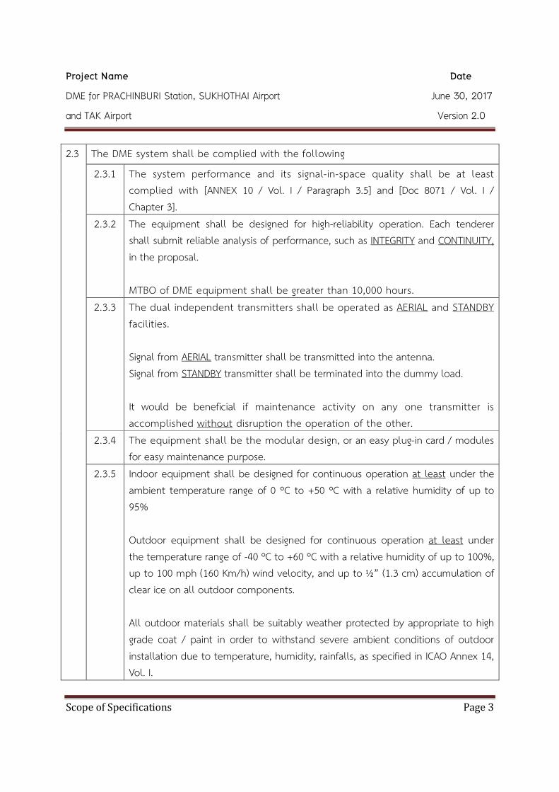
2.3
The DME system shall be complied with the following
2.3.1 The system performance and its signal-in-space quality shall be at least complied with [ANNEX 10 / Vol. I / Paragraph 3.5] and [Doc 8071 / Vol. I / Chapter 3].
2.3.2 The equipment shall be designed for high-reliability operation. Each tenderer shall submit reliable analysis of performance, such as INTEGRITY and CONTINUITY, in the proposal. MTBO of DME equipment shall be greater than 10,000 hours.
2.3.3 The dual independent transmitters shall be operated as AERIAL and STANDBY facilities. Signal from AERIAL transmitter shall be transmitted into the antenna. Signal from STANDBY transmitter shall be terminated into the dummy load. It would be beneficial if maintenance activity on any one transmitter is accomplished without disruption the operation of the other.
2.3.4 The equipment shall be the modular design, or an easy plug-in card / modules for easy maintenance purpose.
2.3.5 Indoor equipment shall be designed for continuous operation at least under the ambient temperature range of 0 ºC to +50 ºC with a relative humidity of up to 95% Outdoor equipment shall be designed for continuous operation at least under the temperature range of -40 ºC to +60 ºC with a relative humidity of up to 100%, up to 100 mph (160 Km/h) wind velocity, and up to ½” (1.3 cm) accumulation of clear ice on all outdoor components. All outdoor materials shall be suitably weather protected by appropriate to high grade coat / paint in order to withstand severe ambient conditions of outdoor installation due to temperature, humidity, rainfalls, as specified in ICAO Annex 14, Vol. I.

Project Name Date
DME for PRACHINBURI Station, SUKHOTHAI Airport June 30, 2017
and TAK Airport Version 2.0
Scope of Specifications Page 4
2.4 Power supply supporting the DME system shall be complied with following : 2.4.1 Single phase AC power system with 220 VAC ± 15%, 50 Hz ± 5%. shall be
provided to all DME and peripheral equipment. 2.4.2 The UPS & STS system for DME system shall be provided and installed at each
DME station (see Fig. 4-1) The full system is composed of the following :
2.4.2.1 Two (2) sets of UPS and their associated BACKUP batteries at each DME station. Each set of maintenance-free battery shall be capable of operation at least 15 minutes in the event of main AC failure. The specification of UPS system is specified in [4.1].
2.4.2.2 Two (2) sets of STS at each DME station. The specification of STS system is specified in [4.2].
2.4.2.3 Like the DME system, all monitoring and control equipment for UPS & STS system is also specified in [5].
2.4.3 BACKUP battery (with charger unit) for DME equipment shall also be included in the power supply system and shall have sufficient capacity to enable the equipment operate for a minimum period of three (3) hours in the event of an AC-main failure. BACKUP battery shall be maintenance-free sealed lead-acid type. Note that, this equipment is not the same part as BACKUP battery used for supporting the UPS system [2.4.2.1].
2.5
AC/DC power lines, transmission lines, control lines, test cables and all relevant accessories, supporting the DME system shall be complied with the following : 2.5.1 All AC/DC power lines, transmission lines, control lines and relevant accessories
(e.g. connectors, cable trays, conduits and cable ties) shall be provided by the contractor.
If the installation work involved with the buried cables. Those shall be “underground-type” and fitted in HDPE or RSC pipes which the inner diameter shall be wide enough for fitting all cables easily.

Project Name Date
DME for PRACHINBURI Station, SUKHOTHAI Airport June 30, 2017
and TAK Airport Version 2.0
Scope of Specifications Page 5
2.5.2 All transmission lines shall be laid in a different pipe separated from that of AC
power lines. Additionally, all RF connectors shall be complied with IEC 61169-16 international standard or equivalent.
2.5.3 All known power lines, transmission lines and control lines shall be marked out by the contractor.
2.5.4 If provided, The underground cable work shall be done by the contractor. The trench for lying underground cable shall be dug more than 50 cm in depth from ground surface and not less than 30 cm in width. The trench basement shall be covered with 20 cm thick of sand which is the base of underground cable. Finally, the underground cable shall be covered with 20 cm thick of sand topping with 20 cm thick of soil. The contractor shall be responsible for any damages to existing underground equipment and utilities. The cable route markers shall be installed at every 10 meters for indicating underground cable route, and shall follow specifications as detailed in Section 2 : Civil Work and Grounding System Requirements.
2.5.5 All relevant accessories necessary for initial set up, maintenance, or else system calibration (BOTH transmitter AND monitor calibration) shall be provided, as specified in [10.1]
2.6 Lightning protection, surge protection and grounding system supporting the DME system shall be complied with the following : 2.6.1 All above system shall be complied with the related IEC-62305 international
standard or equivalent. The tenderer shall also submit all related certified document as evidence.

Project Name Date
DME for PRACHINBURI Station, SUKHOTHAI Airport June 30, 2017
and TAK Airport Version 2.0
Scope of Specifications Page 6
2.6.2 The tenderer shall submit and detail the interconnection diagram of complete protection system in the proposal (including brand, and model of the equipment). Complete protection system shall include all of the lightning protection, surge protection and grounding system.
2.6.3 The lightning protection system shall adequately protect all of the DME and peripheral equipment in the event of a lightning strike.
2.6.4 The surge protection system shall be provided to all POWER line, RF cable and TELECOM line. Each surge protection unit of POWER line shall also be embedded with an indicator to alarm when damage /failure occur. However, this is not necessary required for surge protection unit of RF line and TELECOM line. The surge protection system of microwave link [see 6.1.2] shall be not provided by the contractor, It is AEROTHAI’s responsibility. 2.6.4.1 POWER surge protection shall meet at least the following specification :
2.6.4.1.1 Maximum Continuous Operating Voltage (Uc) at least 320 VAC. 2.6.4.1.2 Voltage Protection Level (Up) less than 1.5 KV. 2.6.4.1.3 Maximum Discharge Current (Imax) (8/20 sµ ) at least 100 KA.
2.6.5 The grounding system shall provide the total resistance not exceed 5 Ω.

Project Name Date
DME for PRACHINBURI Station, SUKHOTHAI Airport June 30, 2017
and TAK Airport Version 2.0
Scope of Specifications Page 7
3. Specifications of DME/N [E] 3.1
Transponder characteristics 3.1.1 The system shall operate with vertical polarization in the frequency band of 960
MHz to 1215 MHz, with 1 MHz spacing between channels. The interrogation and reply frequencies shall be paired [ANNEX10 / Vol. I – Table A / p.3-100].
3.1.2 The operating channels of all DME/DME systems are specified in APPENDIX A. 3.1.3 BOTH the operating frequency of the reply signal AND the centre frequency
of the receiver shall not vary more than ± 0.002 % from the assigned frequency [ANNEX 10 / Vol. I / Paragraph 3.5.4.1.2, and 3.5.4.2.2]. Frequency setting shall be adjusted by means of software.
3.1.4 About the transponder sensitivity to cause the transponder to reply with an efficiency of at least 70% [ANNEX 10 / Vol. I / Paragraph 3.5.4.2.3.1, 3.5.4.2.3.2, 3.5.4.2.3.5 and 3.5.4.2.3.6] NOTE : The airborne equipment sensitivity stated in [ANNEX 10 / Vol. I / Paragraph 3.5.5.3.2.1] shall be not involved in this scope of specifications. 3.1.4.1 When DME collocated with VOR or else standalone such that
supporting DME/DME network – DME RNAV operation, interrogation pulse pairs with correct spacing and nominal frequency shall trigger the transponder if the peak power density at THE TRANSPONDER ANTENNA is at least -103 ± 1 dBW/m2.
3.1.5 Bandwidth and selectivity shall meet the requirements specified in [ANNEX 10 / Vol. I / Paragraph 3.5.4.2.6] such that for each deviated interrogation frequency : 3.1.5.1 The received signal, ±f 200 KHz from the center frequency, should be
suppressed not more than 3 dB. 3.1.5.2 The received signal, ±f 900 KHz from the center frequency, should be
suppressed more than 80 dB. 3.1.5.3 Any spurious signal from other DME channel, should be suppressed
more than 75 dB.

Project Name Date
DME for PRACHINBURI Station, SUKHOTHAI Airport June 30, 2017
and TAK Airport Version 2.0
Scope of Specifications Page 8
3.1.6 DME/N-Decoder Rejection. An interrogation pulse pair with a spacing of ± 2
sµ , or more from the nominal value, shall be rejected [ANNEX 10 / Vol. I / Paragraph 3.5.4.3.3].
3.1.7 System time reference should be configurable between 1st or 2nd pulse timing, if not, it shall be 1st pulse timing system.
3.1.8
Pulse shape and spectrum of pulse modulated signal shall meet the requirements of [ANNEX 10 / Vol. I / Paragraph 3.5.4.1.3 and 3.5.5.1.3]. 3.1.8.1 Pulse rise time (between 10 to 90% of the leading edge) ≤ 3 sµ 3.1.8.2 Pulse decay time (between 10 to 90% of trailing edge) ≈ 2.5 sµ , and
≤ 3.5 sµ 3.1.8.3 Pulse duration (between 50% of the leading, and trailing edges)
≤ (3.5± 0.5) sµ 3.1.8.4 The instantaneous amplitude of the pulse does not, at any instant
between the point on the leading edge which is 95% of the maximum amplitude and the point on the trailing edge which is 95% of the maximum amplitude, fall below a value which is 95% of the maximum amplitude of the pulse.
3.1.9 Pulse pair spacing shall be (12.0± 0.1) sµ or else should be (12.0± 0.25) sµ [ANNEX 10 / Vol. I / Paragraph 3.5.4.1.4]. The peak power of the constituent pulses of any transponder pulse pair shall not differ by more than one (1) dB. [ANNEX 10 / Vol. I / Paragraph 3.5.4.1.5.4]
3.1.10 Reply delay, between 50% amplitude of the 1st (or 2nd) leading edge of the interrogation and reply pulses should be typically 50 sµ for X-channel, and adjustable at least between 35 to 50 sµ [ANNEX 10 / Vol. I / Paragraph 3.5.4.4.1 and 3.5.4.4.3].
3.1.11 Pulse width, pulse pair spacing and reply delay shall be adjustable by means of software to the specified values without removing any module from the assembly.

Project Name Date
DME for PRACHINBURI Station, SUKHOTHAI Airport June 30, 2017
and TAK Airport Version 2.0
Scope of Specifications Page 9
3.1.12 Dead time, short distance echo suppression and long distance echo suppression shall be adequately adjustable for each DME station installed, in order to prevent any undesired signal degrading the system performance [ANNEX 10 / Vol. I / Paragraph 3.5.4.2.9 and 3.5.4.3].
3.1.13 The transponder shall be capable of continuous operation at a transmission rate (the so-called “Pulse Repetition Rate”) at least between 700 to 4800 pps. Where the nominal rate should be 2,700 ± 90 pps (if 100 aircraft are to be served).
3.1.14 Thee DME identification system shall support three letters international Morse Code and also meet the requirements specified in [ANNEX 10 / Vol. I / Paragraph 3.5.3.6].
3.1.15 About the power amplifier. 3.1.15.1 When DME collocated with VOR or else standalone such that
supporting DME/DME network – DME RNAV operation, The power amplifier of the transponder shall be capable of providing full peak output power of not less than 1000 watts to the antenna.
3.1.15.2 Protection against open or short circuit from damages / loss shall be strictly provided for the power amplifier.
3.1.16 DME equipment shall provide / embed the coupling port for measuring peak output power without shutdown / turn OFF the equipment.
3.1.17 The transponder shall not contribute more than ± 1 sµ to the overall system error (relative to accuracy) [ANNEX 10 / Vol. I / Paragraph 3.5.4.5.1].
3.1.18 The tenderer shall also submit all related document to guarantee that your proposed GND facility provide the DME RF coverage NOT less than the minimum requirement of ICAO. If the DME system is installed and configured properly. It shall provide signal POWER with sufficient to DME/N protected coverage. [Figure C-20 of ANNEX 10 / Vol. I / Attachment C / Paragraph 7.2.1], or else see APPENDIX B.

Project Name Date
DME for PRACHINBURI Station, SUKHOTHAI Airport June 30, 2017
and TAK Airport Version 2.0
Scope of Specifications Page 10
3.2
Monitor characteristics 3.2.1
The monitoring system of DME shall serve three (3) purposes. 3.2.1.1 To be used as monitoring basic maintenance parameters e.g. power
supply voltage, Digital I/O, BITE, BYPASS /changeover mode, synthesized frequency, RF Power amplifier data, antenna VSWR, environmental sensing, version of module/CCA etc. It would be beneficial if the monitoring system be able to detect, diagnostic and identify the faulty parts of the system in a correct manner, such as “Module/CCA” faults, “Transmission Line” faults and “Antenna” fault, etc.
3.2.1.2 To be used as a “Test Signal Generator” in conjunction with a built-in test unit for calibration and testing whether the detection capability of the monitoring system be working properly. 3.2.1.2.1 Be able to generate pulse pair both “in” and “out-of-
tolerance” condition. 3.2.1.2.2 Be able to select /adjust the deviated frequency of
simulated interrogation signals, at least from 0 to ± 900 KHz. (see also 3.1.6)
3.2.1.2.3 Be able to select /adjust the attenuation range of simulated interrogation signals, at least from -91 to -20 dBm, at the input point of a transponder [ANNEX 10 / Vol. I / Paragraph 3.5.4.2.3.3]. Remark : minus 91 dBm is equivalent to minus 103 dBW/m2 in a typical installation.
3.2.1.2.4 Be able to select /adjust the PRF of simulated interrogation signals, at least from 700 to 4800 pps.
3.2.1.2.5 Test Signal Generator shall also provide the test points for analyzing /confirming the correctness of the simulated signal by external measuring equipment (e.g. waveform analyzer).
Project Name Date
DME for PRACHINBURI Station, SUKHOTHAI Airport June 30, 2017
and TAK Airport Version 2.0
Scope of Specifications Page 11
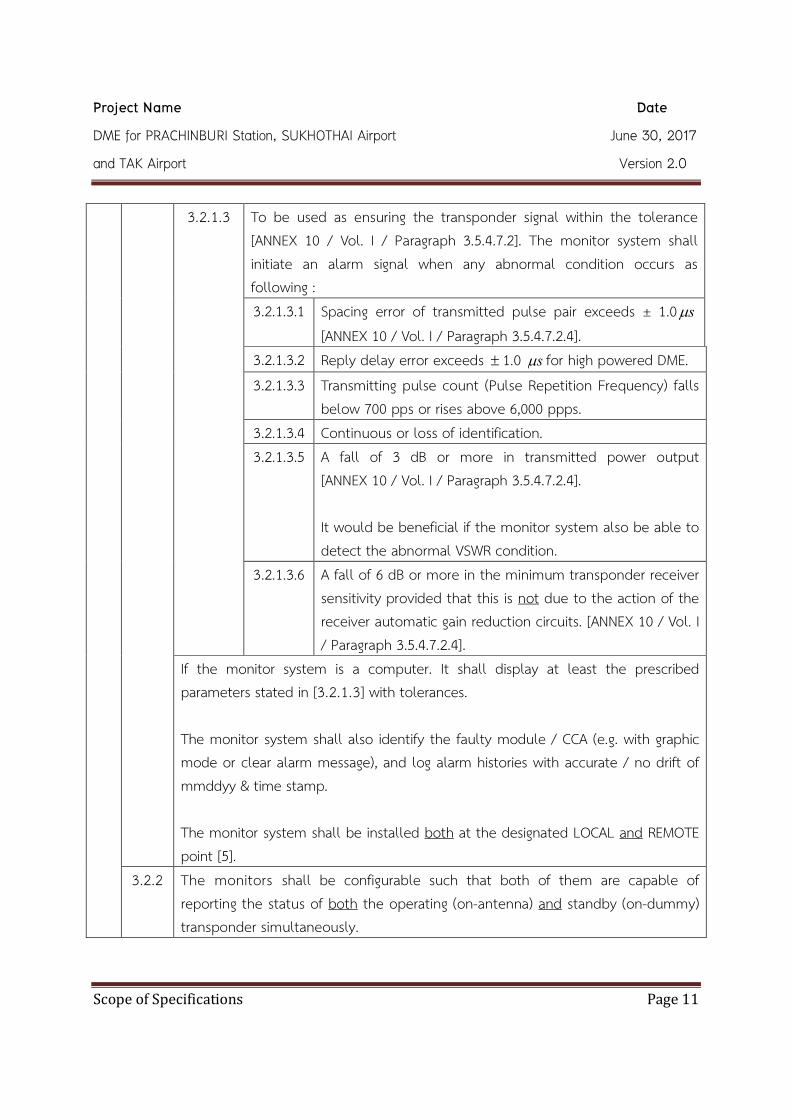
3.2.1.3
To be used as ensuring the transponder signal within the tolerance [ANNEX 10 / Vol. I / Paragraph 3.5.4.7.2]. The monitor system shall initiate an alarm signal when any abnormal condition occurs as following : 3.2.1.3.1 Spacing error of transmitted pulse pair exceeds ± 1.0 sµ
[ANNEX 10 / Vol. I / Paragraph 3.5.4.7.2.4]. 3.2.1.3.2 Reply delay error exceeds ± 1.0 sµ for high powered DME. 3.2.1.3.3 Transmitting pulse count (Pulse Repetition Frequency) falls
below 700 pps or rises above 6,000 ppps. 3.2.1.3.4 Continuous or loss of identification. 3.2.1.3.5 A fall of 3 dB or more in transmitted power output
[ANNEX 10 / Vol. I / Paragraph 3.5.4.7.2.4]. It would be beneficial if the monitor system also be able to detect the abnormal VSWR condition.
3.2.1.3.6 A fall of 6 dB or more in the minimum transponder receiver sensitivity provided that this is not due to the action of the receiver automatic gain reduction circuits. [ANNEX 10 / Vol. I / Paragraph 3.5.4.7.2.4].
If the monitor system is a computer. It shall display at least the prescribed parameters stated in [3.2.1.3] with tolerances. The monitor system shall also identify the faulty module / CCA (e.g. with graphic mode or clear alarm message), and log alarm histories with accurate / no drift of mmddyy & time stamp. The monitor system shall be installed both at the designated LOCAL and REMOTE point [5].
3.2.2 The monitors shall be configurable such that both of them are capable of reporting the status of both the operating (on-antenna) and standby (on-dummy) transponder simultaneously.

Project Name Date
DME for PRACHINBURI Station, SUKHOTHAI Airport June 30, 2017
and TAK Airport Version 2.0
Scope of Specifications Page 12
3.2.3 In case of [3.2.1.3], the monitors shall be configured either in “AND” or “OR” mode for a system changeover /shutdown in the event of failure.
3.2.4 In case of [3.2.1.3], monitoring actions shall be complied with the following :
The primary alarms generated by [3.2.1.3.1] and [3.2.1.3.2] shall initiate a TRANSFER action when the main transponder is operating (on-antenna), or else a SHUTDOWN action when the standby transponder is operating (on-antenna).
The secondary alarm generated by the remaining of [3.2.1.3] shall not affect TRANSFER /SHUTDOWN action, but still display whether the system not working properly.
3.2.5 The monitor should persist for a certain period BEFORE the monitoring action, in order for avoiding interruption, due to transient effects provided by the transponder. This period shall be as low as practicable, but shall not exceed 10 s. [ANNEX 10 / Vol. I / Paragraph 3.5.4.7.2.5].
3.3 DME antenna system 3.3.1 The antenna shall be capable of radiating DME signal throughout the DME
frequency band (960 MHz to 1215 MHz) so that changing of the operating frequency needs no tuning of the antenna.
3.3.2 The antenna gain shall not be less than +9 dBi. 3.3.3 The antenna radiation pattern shall be submitted in the proposal.
3.3.3.1 For the horizontal radiation pattern. 3.3.3.1.1 When DME collocated with VOR or else standalone such
that supporting DME/DME network – DME RNAV operation, the antenna shall be “OMNI-DIRECTIONAL” type.
3.3.3.2 For the vertical radiation pattern. 3.3.4 All the antenna system and related installation shall be WEATHERPROOF
against corrosion and coated with high-grade paint & marking in according to [ANNEX 14 / Vol. I : Obstruction Marking Recommendation].
3.3.5 Double LED obstruction lighting equipment with photo-switch shall be co-installed at the top of DME antenna.

Project Name Date
DME for PRACHINBURI Station, SUKHOTHAI Airport June 30, 2017
and TAK Airport Version 2.0
Scope of Specifications Page 13
The LED obstruction lighting equipment shall be complied with [Annex 14 / Vol. I / Chapter 6] or Federal Aviation Administration (FAA) (AC150/5345-43F or 43G). Additionally, type and model shall be submitted in the proposal.

Project Name Date
DME for PRACHINBURI Station, SUKHOTHAI Airport June 30, 2017
and TAK Airport Version 2.0
Scope of Specifications Page 14
4. Specifications of UPS, STS and Load Centre [E] The conceptual diagram of how to integrate each power supply subsystem, is depicted in Fig.4-1. The monitoring & control equipment for navigation aid and UPS & STS is described in [5]. The complete “Intersystem Connection and Communication Diagram” is described in [8]. 4.1
UPS (Uninterrupted Power Supply)
4.1.1 The UPS shall be “TRUE ONLINE” type with DOUBLE CONVERSION. 4.1.2 “MANUAL BYPASS” switch shall be built in the UPS unit for maintenance purpose.
While the manual bypass switch is selected, the system shall be capable of operating without any interruption of the system operation.
4.1.3 When the UPS is fault (e.g. overcharging, short circuit, overload, etc.) for short period, it shall be capable of automatically transferring the load supplied by the inverter to the reserve line (BYPASS) without any interruption of the system operation. In case of long period, the UPS shall be automatically shutdown. Additionally, UPS shall be able to store event log data in the unit.
4.1.4 The battery system of UPS shall be complied with the following : 4.1.4.1 Protection mechanism shall be provided against damage of
semiconductors due to the battery polarity being inadvertently reversed. 4.1.4.2 The battery charger shall be capable of charging batteries being
completely discharged with high quality. 4.1.4.3 The battery shall also be continuously float charged.
4.1.5 The tenderer shall verify that the proposed (either internal or external) BACKUP battery of the UPS system, is capable of time backup not less than 15 minutes at FULL LOAD. After considering power consumption and backup time at each DME station, If the calculation result indicate that UPS 5 KVA is used, thus STS 32 A shall be applied; However, if the UPS 10 KVA is used, STS 45 A shall be applied.

Project Name Date
DME for PRACHINBURI Station, SUKHOTHAI Airport June 30, 2017
and TAK Airport Version 2.0
Scope of Specifications Page 15
4.1.6 UPS equipment shall be new and factory tested.
The contractor shall also be responsible for demonstrating a complete FULL LOAD field test of the complete power supply system whether it is compatible with AEROTHAI backup generator. Then, the contractor shall provide, install, and test the complete operable system in the specified location, whether it works properly.
4.1.7 Technical specification of UPS
The contractor shall submit product description /technical characteristic of UPS not below the following : 4.1.7.1 Input
4.1.7.1.1 Voltage (Vrms) 230 VAC ± 10% or better 4.1.7.1.2 Frequency 50 Hz ± 2% or better 4.1.7.1.3 Phase Single (2 Wire + GND) 4.1.7.1.4 THD
(Total Harmonic Distortion) ≤10% or better at full load
4.1.7.2 Output 4.1.7.2.1 Voltage (Vrms) 230 VAC ± 1% or better
for both NORMAL and BATTERY mode 4.1.7.2.2 Frequency 50 Hz ± 0.5% or better
for both NORMAL and BATTERY mode 4.1.7.2.3 Number of Phase Single (2 Wire + GND) 4.1.7.2.4 THD
(Total Harmonic Distortion) ≤3% for 100% linear load
4.1.7.2.5 Waveform Sine Wave 4.1.7.2.6 Power Factor 0.8 lag or better 4.1.7.2.7 Crest Factor 3:1 or better 4.1.7.2.8 AC to AC - Overall
Efficiency ≥85% at full load

Project Name Date
DME for PRACHINBURI Station, SUKHOTHAI Airport June 30, 2017
and TAK Airport Version 2.0
Scope of Specifications Page 16
4.1.7.3 Overload Capacity 4.1.7.3.1 110% load 2 minutes or better
4.1.7.4 Short Circuit Capacity 4.1.7.4.1 For nominal voltage condition, the UPS shall be able to resist
the short circuit current not less than 2.5 A for at least 100 msec.
4.1.7.5 Environment 4.1.7.5.1 Ambient Temperature 0 o C to +40 o C (continuous or better) 4.1.7.5.2 Humidity ≥ 90% continuously
with non condensing 4.1.7.6 Audible Noise
4.1.7.6.1 Audible Noise ≤ 55 dB(A) at 1 meter. 4.1.7.7 Battery
4.1.7.7.1 Type Maintenance-free sealed lead-acid 4.1.7.7.2 Frame ABS or better. 4.1.7.7.3 High Rate Discharge 20 hours at approximately 25 o C and
end voltage 1.75 V/C 4.1.7.7.4 Life Time 3 to 5 years at 25 o C or better 4.1.7.7.5 Backup Time ≥ 15 minutes at full load of UPS 4.1.7.7.6 Battery Standard UL94-VO or compatible
4.1.7.8 UPS Standard 4.1.7.8.1
UPS Standard มอก.1291 เลhม 1, 2-2553 มอก.1291 เลhม 3-2555
4.1.8 The monitoring & control equipment for UPS & STS is described in [5]. The complete “Intersystem Connection and Communication Diagram” is described in [8].

Project Name Date
DME for PRACHINBURI Station, SUKHOTHAI Airport June 30, 2017
and TAK Airport Version 2.0
Scope of Specifications Page 17
4.2 STS (Static Transfer Switch) 4.2.1 STS shall be configurable to transfer to another UPS source, by both AUTO and
MANUAL method. For maintenance purpose, MANUAL TRANSFER (the so-called “MAINTENANCE BYPASS”) is typically used for directing the specific source of UPS to load, not passing through to the automatic section. Additionally, MANUAL TRANSFER must be operated in an interlock way (Fig. 4-3).
4.2.2 STS shall transfer only when the UPS source not working properly. If the load (downstream circuit) is short, STS shall not transfer, in order for preventing damages expand to the upstream source.
4.2.3 STS shall be able to RETRANSFER, or back to the DEFAULT source of UPS, when that source is back to the normal condition.
4.2.4 STS equipment shall be new and factory tested. The contractor shall also be responsible for demonstrating a complete FULL LOAD field test of the complete power supply system whether it is compatible with AEROTHAI backup generator. Then, the contractor shall provide, install, and test the complete operable system in the specified location, whether it works properly (see also [4.1.6]).
4.2.5 Technical specification of STS The contractor shall submit product description /technical characteristic of STS not below the following : 4.2.5.1 Input
4.2.5.1.1 Input Voltage (Vrms) 230 VAC± 10% (adjustable) or better 4.2.5.1.2 Input Frequency 50 Hz ± 2% or better 4.2.5.1.3 Number of Phase Single (2 Wire + GND)
4.2.5.2 Output 4.2.5.2.1 Output Voltage (Vrms) 230 VAC± 10% (adjustable) or better 4.2.5.2.2 Rating STS 32 A for UPS 5 KVA or,
STS 45 A for UPS 10 KVA

Project Name Date
DME for PRACHINBURI Station, SUKHOTHAI Airport June 30, 2017
and TAK Airport Version 2.0
Scope of Specifications Page 18
4.2.5.2.3 Overload Capacity (110%) 1 minute or better 4.2.5.2.4 Transfer Time ≤5 ms for automatic transfer
≤10 ms for manual transfer 4.2.5.2.5 Efficiency ≥95%
4.2.5.3 Environments 4.2.5.3.1 Operating Temperature 10-40 o C 4.2.5.3.2 Relative Humidity non-condensed at least 90% 4.2.5.3.3 Noise Level ≤60 dBA
4.2.5.4 Communication Port RS232 standard and TCP/IP 4.2.5.5 Standard IEC 62310 series, EN 62310 series,
or compatible 4.2.6 The monitoring & control equipment for UPS & STS is described in [5]. The
complete “Intersystem Connection and Communication Diagram” is described in [8].

Project Name Date
DME for PRACHINBURI Station, SUKHOTHAI Airport June 30, 2017
and TAK Airport Version 2.0
Scope of Specifications Page 19
GeneratorElectrical
Authority
DME #A
S1
(Automatic Transfer Switch)ATS
AEROTHAI MDB (Main Distribution Board located OUTSIDE of the DME shelter)
AEROTHAI MDB (Main Distribution Board locate INSIDE of the DME shelter)
S2
DME #B
(located in DME shelter)
UPS #A (located in DME shelter)
UPS #B
STS #A (located in DME shelter)
STS #B (located in DME shelter)
Figure 4-1 : Conceptual Diagram of Power Supply Configuration at DME station
Remark : 1. Both UPS #A and UPS #B are supplied with the electrical power from AEROTHAI MDB. 2. The specification of circuit breakers and all associated wires, provided by the contractor, must also be complied with the rate of the UPSs. 3. Fig 4-1, is just a conceptual diagram, the real installation work may be adapted, depend on the personnel in charge; However, still being complied with the standard of ELECTRICAL AUTHORITY.

Project Name Date
DME for PRACHINBURI Station, SUKHOTHAI Airport June 30, 2017
and TAK Airport Version 2.0
Scope of Specifications Page 20
Figure 4-2 : A Comparison of Block Diagrams of Different Types of UPSs.

Project Name Date
DME for PRACHINBURI Station, SUKHOTHAI Airport June 30, 2017
and TAK Airport Version 2.0
Scope of Specifications Page 21
Figure 4-3 : Schematic Diagram of STS
Project Name Date
DME for PRACHINBURI Station, SUKHOTHAI Airport June 30, 2017
and TAK Airport Version 2.0
Scope of Specifications Page 22
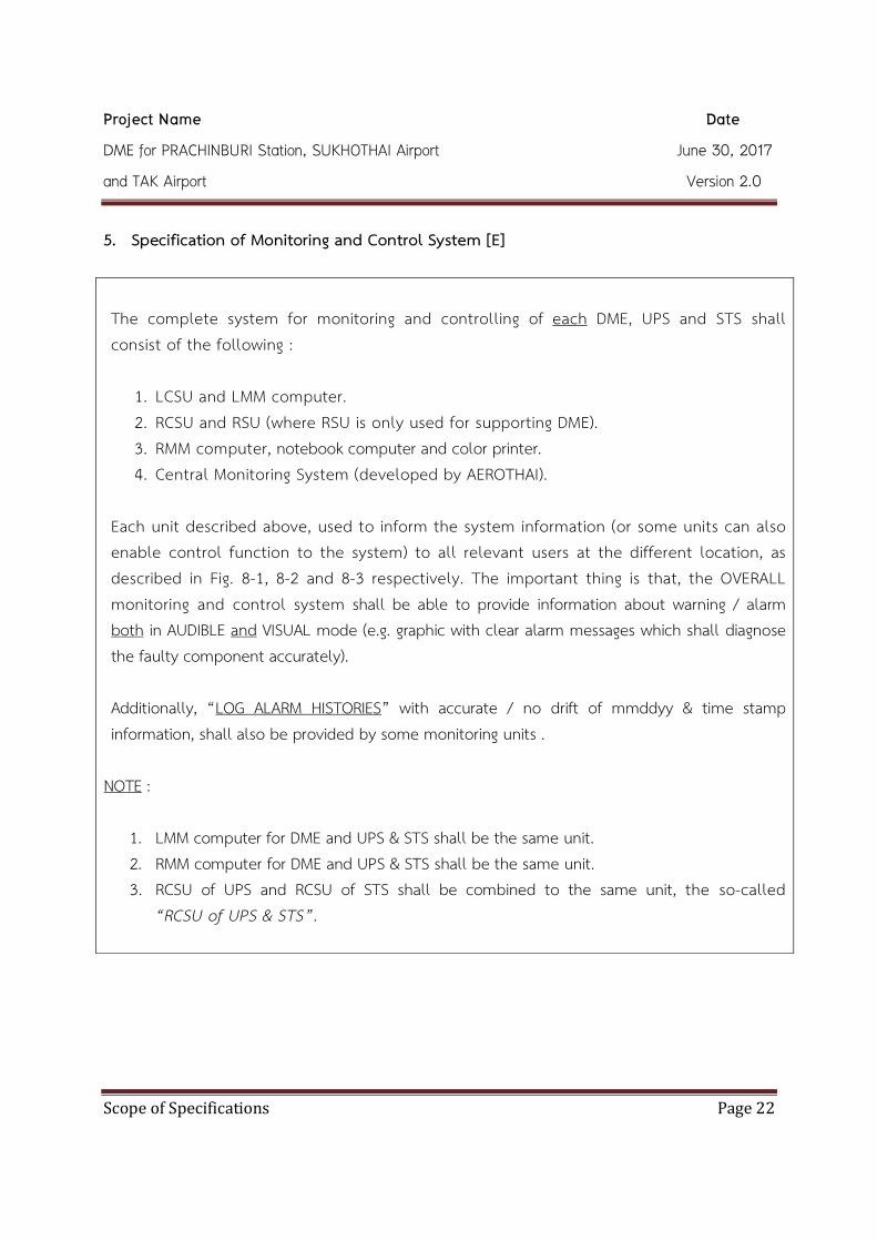
5. Specification of Monitoring and Control System [E] The complete system for monitoring and controlling of each DME, UPS and STS shall consist of the following :
1. LCSU and LMM computer. 2. RCSU and RSU (where RSU is only used for supporting DME). 3. RMM computer, notebook computer and color printer. 4. Central Monitoring System (developed by AEROTHAI).
Each unit described above, used to inform the system information (or some units can also enable control function to the system) to all relevant users at the different location, as described in Fig. 8-1, 8-2 and 8-3 respectively. The important thing is that, the OVERALL monitoring and control system shall be able to provide information about warning / alarm both in AUDIBLE and VISUAL mode (e.g. graphic with clear alarm messages which shall diagnose the faulty component accurately). Additionally, “LOG ALARM HISTORIES” with accurate / no drift of mmddyy & time stamp information, shall also be provided by some monitoring units .
NOTE :
1. LMM computer for DME and UPS & STS shall be the same unit. 2. RMM computer for DME and UPS & STS shall be the same unit. 3. RCSU of UPS and RCSU of STS shall be combined to the same unit, the so-called
“RCSU of UPS & STS”.

Project Name Date
DME for PRACHINBURI Station, SUKHOTHAI Airport June 30, 2017
and TAK Airport Version 2.0
Scope of Specifications Page 23
5.1
Local Control and Status Unit (LCSU) and LMM computer 5.1.1 LCSU is a unit used for monitoring and controlling the equipment LOCALLY at
each DME, UPS and STS equipment. There are three (3) parts of LCSU -- LCSU of DME, LCSU of UPS and LCSU of STS. Typically, each of them is a BUILT-IN unit for each prescribed equipment.
5.1.2 LCSU of DME shall provide the functions described in Table 5.1. LCSU of UPS shall provide at least mimic diagram for monitoring subsystem (e.g. line input, inverter, output, load on bypass, battery mode and fault - main fail, low battery, overload -, etc.) and some necessary controlling subsystem. LCSU of STS shall provide at least, mimic diagram monitoring subsystem and some necessary controlling subsystem.
5.1.3 A desktop computer provided for each navigation aids equipment, the so-called “LMM Computer”, stated as a part of LOCAL monitoring and controlling unit, shall be complied with [7.1]. One (1) LMM computer shall be provided at each DME station. The software for monitoring and controlling the DME, UPS and STS equipment shall be commonly installed in the same LMM computer. Each operating system shall be WINDOWS-BASED. The recovery CD/DVD (or any portable data storage devices) and the user’s license for the software shall be provided for AEROTHAI. LMM software shall be able to provide information about warning / alarm both in AUDIBLE and VISUAL mode (e.g. graphic with clear alarm messages which shall diagnose the faulty component accurately as well as log alarm histories with accurate / no drift of mmddyy & time stamp information).

Project Name Date
DME for PRACHINBURI Station, SUKHOTHAI Airport June 30, 2017
and TAK Airport Version 2.0
Scope of Specifications Page 24
5.2
Remote Control and Status Unit (RCSU) 5.2.1 RCSU is a unit used for monitoring and controlling the equipment REMOTELY at
the technical control room of ATC tower. RCSU of UPS and RCSU of STS shall be combined to the same unit, the so-called “RCSU of UPS & STS”. Therefore, there are two (2) parts of RCSU -- RCSU of DME and RCSU of UPS & STS and their dimensions shall be of the same width.
5.2.2 RCSU of DME shall provide the functions described in Table 5.1. RCSU of UPS & STS shall provide at least mimic diagram for monitoring subsystem (e.g. line input, inverter, output, load on bypass, battery mode and fault - main fail, low battery, overload -, etc.) and some necessary controlling subsystem.
5.2.3 The intersystem connection between each equipment (DME, UPSs and STSs) and its own RCSU shall be configured in a redundant manner (see also Fig. 8-1, 8-2, and 8-3) -- The primary connection and the secondary connection. The selection capability of using which connection shall also be provided.
5.2.4 The system information OUTPUT (e.g. warning & alarm status / messages or else monitoring parameters) of each RCSU shall support “Simple Network Management Protocol (SNMP)” for AEROTHAI self developing the CENTRAL MONITORING SYSTEM in the future.
5.3 Remote Status Unit (RSU) 5.3.1 RSU is a unit used only for monitoring the equipment REMOTELY at the ATC
room of the ATC tower. There is one (1) part of RSU -- RSU of DME. RSU of UPS & STS is not used. The contractor shall not submit the proposal.
5.4 Remote Maintenance Monitoring (RMM) 5.4.1 RMM is a unit used for monitoring and controlling the equipment REMOTELY at
the technical control room of the ATC tower.
Project Name Date
DME for PRACHINBURI Station, SUKHOTHAI Airport June 30, 2017
and TAK Airport Version 2.0
Scope of Specifications Page 25
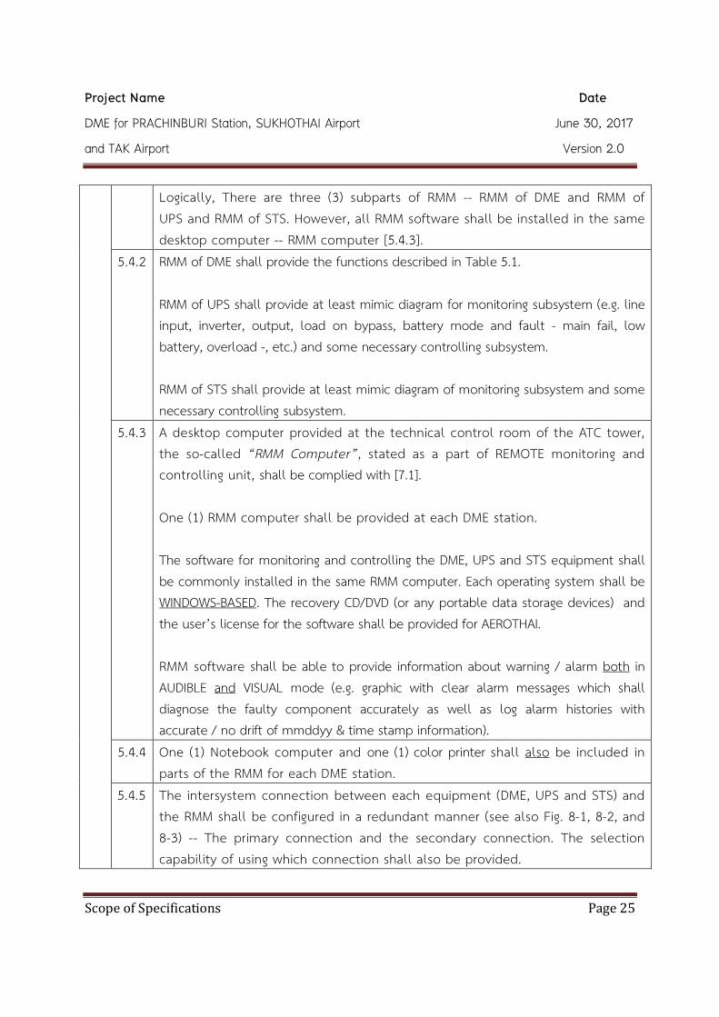
Logically, There are three (3) subparts of RMM -- RMM of DME and RMM of UPS and RMM of STS. However, all RMM software shall be installed in the same desktop computer -- RMM computer [5.4.3].
5.4.2 RMM of DME shall provide the functions described in Table 5.1. RMM of UPS shall provide at least mimic diagram for monitoring subsystem (e.g. line input, inverter, output, load on bypass, battery mode and fault - main fail, low battery, overload -, etc.) and some necessary controlling subsystem. RMM of STS shall provide at least mimic diagram of monitoring subsystem and some necessary controlling subsystem.
5.4.3 A desktop computer provided at the technical control room of the ATC tower, the so-called “RMM Computer”, stated as a part of REMOTE monitoring and controlling unit, shall be complied with [7.1]. One (1) RMM computer shall be provided at each DME station. The software for monitoring and controlling the DME, UPS and STS equipment shall be commonly installed in the same RMM computer. Each operating system shall be WINDOWS-BASED. The recovery CD/DVD (or any portable data storage devices) and the user’s license for the software shall be provided for AEROTHAI. RMM software shall be able to provide information about warning / alarm both in AUDIBLE and VISUAL mode (e.g. graphic with clear alarm messages which shall diagnose the faulty component accurately as well as log alarm histories with accurate / no drift of mmddyy & time stamp information).
5.4.4 One (1) Notebook computer and one (1) color printer shall also be included in parts of the RMM for each DME station.
5.4.5 The intersystem connection between each equipment (DME, UPS and STS) and the RMM shall be configured in a redundant manner (see also Fig. 8-1, 8-2, and 8-3) -- The primary connection and the secondary connection. The selection capability of using which connection shall also be provided.

Project Name Date
DME for PRACHINBURI Station, SUKHOTHAI Airport June 30, 2017
and TAK Airport Version 2.0
Scope of Specifications Page 26
Table 5.1 : The functions of each monitoring & controlling subsystem of the DME equipment.
ID Functions LCSU RCSU RSU RMM 1 Display the operating status and generate VISUAL and
AUDIO warning / alarm (with volume control) when failure occur.
X X X X
2 Automatically transfer from the selected transponder to a standby transponder or else shutdown in the event of an alarm.
X - - -
3 Select the LOCAL / REMOTE control. X - - - 4 Select the MAIN / STANDBY transponder or at least
manually turn ON / OFF and changeover the selected transponder with indicator.
X X - X
5 BYPASS the monitor. X X - X 6 RESET / RESTART the system. X X - X 7 Adjust the system (both TRANSPONDER and MONITOR)
parameter. See
[5.1.3] - - See
[5.4.3]

Project Name Date
DME for PRACHINBURI Station, SUKHOTHAI Airport June 30, 2017
and TAK Airport Version 2.0
Scope of Specifications Page 27
6. Specifications of Network Equipment for all Navigation Aids and UPS & STS Systems [E] This section will detail all the network equipment necessary for implementing the complete REMOTE monitoring and controlling system.
1. The monitoring and controlling equipment for all navigation aids and UPS & STS is described in [5].
2. The network equipment for all navigation aids and UPS & STS is described in [6]. 3. The “Intersystem Connection and Communication Diagram” is described in [8].
6.1 Local Network Equipment
(From the navigation aids to the technical control room) Appeared in Fig. Responsible
by 8-1 8-2 8-3 6.1.1 Optical fiber [6.5] - AEROTHAI
6.1.2 Microwave link [6.6] (including its surge protection system)
- AEROTHAI
6.1.3 ISP (Internet Service Provider) media (see Fig.8-3) - - AEROTHAI
6.1.4 L3 Switch [6.3] Contractor
6.1.5 VPN router [6.4] (Both VPN router and firewall may be combined to the same unit)
- - Contractor
6.1.6 Firewall [6.4] (Both VPN router and firewall may be combined to the same unit)
- - Contractor
6.1.7 Serial to LAN converter (Only if navigation aids cannot provide RMM / RCSU Ethernet output [2.2.2.2], [2.2.2.3])
Contractor
6.1.8 Other equipment or accessories NOT mentioned above, but necessary to complete the intersystem connection.
- - - Contractor

Project Name Date
DME for PRACHINBURI Station, SUKHOTHAI Airport June 30, 2017
and TAK Airport Version 2.0
Scope of Specifications Page 28
6.2 Remote Network Equipment (From the technical control room to the central monitoring office at MAHAMEK)
Appeared in Fig. Responsible by 8-1 8-2 8-3
6.2.1 (None) - - - AEROTHAI
6.3 L3 Switch Specifications
The tenderers shall propose the technical specifications of the L3 Switch which comply with or are better than the following specifications. 6.3.1 Capable of switching and routing in both Layer 2 (data link) and Layer 3
(network). 6.3.2 Forwarding bandwidth or Switching Capacity shall be at least 100 Gbps. 6.3.3 Have at least 24 ports of RJ45 Gigabit Ethernet (10/100/1000 Mbps). 6.3.4 2 ports of SFP Gigabit Ethernet or better, and 1 port of LX SFP. 6.3.5 The switch must be stackable up to 8 stack members. 6.3.6 The stack throughput shall be up to 80 Gbps. 6.3.7 Support 1,000 concurrent active VLANs or better. 6.3.8 Can contain at least 8,000 MAC addresses. 6.3.9 Support both IPv4 and IPv6. 6.3.10 Support Static, RIP, RIPng, OSPFv2, OSPFv3 routing protocols. 6.3.11 Configurable Access Control List for both IPv4 and IPv6. 6.3.12 Support IEEE 802.1X security authentication. 6.3.13 Support Port Security, DHCP Protection, Dynamic ARP. 6.3.14 Can be configured in link aggregation which complies with IEEE 802.3ad standard. 6.3.15 Support Spanning Tree protocol as specified in IEEE 802.1D standard. 6.3.16 Capable of both ingress and egress port mirroring from a port on either the same
device or other devices. 6.3.17 Manageable with CLI, GUI, SSH, SNMPv2c/3. 6.3.18 Compatible with 220 VAC ± 15%, 50 Hz ± 5% power, or better.

Project Name Date
DME for PRACHINBURI Station, SUKHOTHAI Airport June 30, 2017
and TAK Airport Version 2.0
Scope of Specifications Page 29
6.4
Firewall and VPN Router Specifications The tenderers shall propose the technical specifications of the Firewall and VPN Router which comply with or are better than the following specifications. 6.4.1 Categorized as Next Generation Firewall Appliance. 6.4.2 Have at least 1 Console port. 6.4.3 At least 8 ports of 10/100/1000 Mbps Base-T. 6.4.4 Firewall throughput with Application Control shall not be less than 250 Mbps. 6.4.5 Firewall throughput with IPS shall not be less than 100 Mbps. 6.4.6 VPN throughput (IPSec Encryption) shall be at least 50 Mbps. 6.4.7 Capable of IPSec tunneling for at least 50 tunnels. 6.4.8 Support IPv4 and IPv6. 6.4.9 Support Static, RIP, OSPFv2/v3 with graceful restart, BGP with graceful restart
routing protocols. 6.4.10 Support Bidirectional Forwarding Detection (BFD). 6.4.11 Support Point-to-Point Protocol over Ethernet (PPPoE). 6.4.12 Support Routing Policy-based forwarding. 6.4.13 Support IPv4 Network Address Translation (NAT) with both static and dynamic IP,
and support Port Address Translation (PAT). 6.4.14 Capable of Dynamic Site-to-Site IPSec VPN configuration 6.4.15 Support the following IPSec Key Exchange types: Manual Key, Pre-shared Key,
Certificate-based. 6.4.16 Support 3DES and AES (128 bits, 256 bits) IPSec Encryption. 6.4.17 Support the following IPSec Authentication types: MD5, SHA-1, SHA-256, SHA-384,
SHA-512. 6.4.18 Capable of creating at least 4000 VLANs each of which complies with 802.1q
standard. 6.4.19 Can be configured in link aggregation which complies with IEEE 802.3ad standard. 6.4.20 Support Active/Passive High Availability. 6.4.21 At least 50 GB of internal storage. 6.4.22 Manageable with CLI, GUI, SSH, SNMPv2c/3. 6.4.23 Compatible with 220 VAC ± 15%, 50 Hz ± 5% power, or better.

Project Name Date
DME for PRACHINBURI Station, SUKHOTHAI Airport June 30, 2017
and TAK Airport Version 2.0
Scope of Specifications Page 30
6.5
Optical Fiber System Specifications (No detail due to it is AEROTHAI’s responsibility).
6.6 Microwave Link (including its surge protection system) Specifications (No detail due to it is AEROTHAI’s responsibility).

Project Name Date
DME for PRACHINBURI Station, SUKHOTHAI Airport June 30, 2017
and TAK Airport Version 2.0
Scope of Specifications Page 31
7. Specifications of Desktop Computer and Notebook Computer 7.1 Desktop Computer
The tenderers shall provide the Desktop Computer including all attached devices that are installed for system operation and monitoring. The tenderers shall propose the technical specifications of the Desktop Computer which comply with or are better than the following specifications.
7.1.1 Desktop, display and keyboard shall be produced from the same manufacturer with permanent logo/brand on products.
7.1.2 Processor/Chipset. 7.1.2.1 Technology of CPU – 22 nm, or smaller. 7.1.2.2 4 Cores and 4 Threads, or more. 7.1.2.3 Base clock frequency – 3.0 GHz, or better.
7.1.3 RAM 7.1.3.1 Capacity – 8 GB, or better.
7.1.4 One (1) Hard Disk Drive. 7.1.4.1 Capacity – 1.0 TB, or better.
7.1.5 One (1) Optical Disc Drive. 7.1.5.1 Internal DVD +/- RW Drive.
7.1.6 Graphic Controller 7.1.6.1 Built-in graphic or discrete graphic.
7.1.7 One (1) Display 7.1.7.1 21.5 inches LED with resolution 1920 x 1080 pixels.
7.1.8 Networking 7.1.8.1 Built-in on board.
7.1.9 Audio Output 7.1.9.1 Sound output including speakers.
7.1.10 I/O Interfaces 7.1.10.1 Minimum four (4) ports of USB. 7.1.10.2 One (1) Serial port or one (1) conversion device for converting USB
to Serial port.

Project Name Date
DME for PRACHINBURI Station, SUKHOTHAI Airport June 30, 2017
and TAK Airport Version 2.0
Scope of Specifications Page 32
7.1.11 One (1) Keyboard 7.1.11.1 Standard QWERTY keyboard with USB interface. 7.1.11.2 104 keys at minimum. 7.1.11.3 Each key shall be permanently printed with both Thai and English
characters. 7.1.12 One (1) Mouse
7.1.12.1 Optical Mouse with scroll wheel. 7.1.12.3 A suitable mouse pad.
7.1.13 Operating System / Software 7.1.13.1 Shall be installed with the Desktop Computer. 7.1.13.2 Capable of operating with the software of the proposed DME
system. 7.1.13.3 Recovery CD/DVD or portable storage devices with a copyright
shall be provided. 7.1.14 The operating system and license which is suitable for computer operation
shall be provided. 7.1.15 The Contractor shall provide to the Desktop Computer a minimum two (2)
year manufacturer warranty. 7.1.16 The Desktop Computer shall have a manufacturer branch office authorized
representative in Thailand. 7.1.17 The CD/DVD or portable storage devices for software driver shall be provided
with the product.

Project Name Date
DME for PRACHINBURI Station, SUKHOTHAI Airport June 30, 2017
and TAK Airport Version 2.0
Scope of Specifications Page 33
7.2
Notebook Computer The Tenderers shall provide the Notebook Computer including all attached devices that are installed for system operation and monitoring. The Tenderers shall propose the technical specifications of the Notebook Computer which comply with or are better than the following specifications. 7.2.1 Processor/Chipset
7.2.1.1 Technology of CPU – 22 nm, or smaller. 7.2.1.2 2 Cores and 4 Threads, or more. 7.2.1.3 Base clock frequency – 2.5 GHz, or better.
7.2.2 RAM 7.2.2.1 Capacity : 8 GB, or better.
7.2.3 One (1) Hard Disk Drive 7.2.3.1 Capacity : 1.0 TB, or better.
7.2.4 One (1) Optical Disc Drive 7.2.4.1 Internal DVD +/- RW Drive.
7.2.5 Graphic Controller 7.2.5.1 Built-in graphic with a minimum of 2 GB dedicated memory.
7.2.6 One (1) Display 7.2.6.1 14 or 15 inches LED.
7.2.7 Internal Wireless LAN 7.2.7.1 Compliant with IEEE 802.11b/g/n standard.
7.2.8 Networking 7.2.8.1 Built-in on board. 7.2.8.2 RJ-45 interface type.
7.2.9 Audio Output 7.2.9.1 Sound output including built-in stereo speakers.
7.2.10
I/O Interfaces 7.2.10.1 Minimum three (3) ports of USB. 7.2.10.2 One (1) Serial port or one (1) conversion device for converting USB
to Serial port. 7.2.10.3 One (1) VGA port or one (1) conversion device for converting
existing display output port to VGA port.

Project Name Date
DME for PRACHINBURI Station, SUKHOTHAI Airport June 30, 2017
and TAK Airport Version 2.0
Scope of Specifications Page 34
7.2.11 One (1) Keyboard 7.2.11.1 Each key shall be permanently printed with both Thai and English
characters. 7.2.12 One (1) Mouse
7.2.12.1 Optical Mouse with scroll wheel. 7.2.12.3 A suitable mouse pad.
7.2.13 Battery 7.2.13.1 Lithium Ion rechargeable.
7.2.14 Operating System / Software 7.2.14.1 Shall be installed with the Notebook Computer. 7.2.14.2 Capable of operating with the software of the proposed DME
system. 7.2.14.3 Recovery CD/DVD or portable storage devices with a copyright
shall be provided. 7.2.15 The operating system and license which is suitable for computer operation
shall be provided. 7.2.16 The Notebook Computer shall have a manufacturer branch office authorized
representative in Thailand. 7.2.17 Operating manual and the CD/DVD or portable storage devices for software
driver shall be provided with the product. 7.2.18 The weight of Notebook Computer including battery shall not exceed
2.5 Kilograms. 7.2.20 The Contractor shall provide to the Notebook Computer a minimum two (2)
year manufacturer warranty.

Project Name Date
DME for PRACHINBURI Station, SUKHOTHAI Airport June 30, 2017
and TAK Airport Version 2.0
Scope of Specifications Page 35
8. Intersystem Connection and Communication Diagram [E] This section will depict the integration of all related equipment stated in [3], [4], [5], [6] and [7] into a complete DME system. 8.1 The tenderer shall submit the proposal of the intersystem connection and
communication diagram which can ACTUALLY be provided. (see also Fig. 8-1, 8-2, and 8-3 for a guideline, and Table 8.1 for the type of network architecture of each DME system).
8.2 For redundancy purpose. The intersystem connection between all DME equipment (including the associated UPS & STS equipment) and the remote monitoring & controlling system (RCSUs and RMM computer) shall be provided via primary connection and secondary connection. The priority of the connections is optical fiber, microwave link, and ISP (Internet Service Provider) media, respectively (see Fig. 8-1 to 8-3)
8.3 The contractor shall provide the following equipment in order to fulfill each of a complete DME system. 8.3.1 All monitoring and controlling equipment stated in [5] : LMM computer for
DME station, RCSU of DME, RCSU of UPS & STS, RSU of DME and RMM computer.
8.3.2 All Local network equipment as stated in [6.1.4] to [6.1.8]. However, all remote network equipment shall be AEROTHAI’s responsibility.
8.4 The contractor shall provide or detail the information exchange (e.g. standard documents, interface control documents (ICDs), etc.) at the output of all RCSUs for AEROTHAI self developing the CENTRAL MONITORING SYSTEM.
8.5 The contractor shall provide the protection system (see also [2.6]) to prevent all equipment from damages in the event of a lightning strike.
8.6 The contractor shall provide or detail the mechanism to provide data integrity and security against unauthorized access -- intrusion and malicious computer attacks.

Project Name Date
DME for PRACHINBURI Station, SUKHOTHAI Airport June 30, 2017
and TAK Airport Version 2.0
Scope of Specifications Page 36
Network Type A
Fig. 8-1 : Type A – Intersystem connection of DME and UPS & STS System (Navigation aid station and technical control room are at the same airside)
AEROTHAI
IP CLOUD
RCSU for UPS & STS
LANRS-232 RCSU for DME
UNI
(Optional)
SNMP Protocol
(Optional)
L3 Switch
RMM Computer(Supporting both DME and UPS & STS)
(Optional)
Surge Protector
RS-232LAN
Wireless Link
Surge Protector
RS-232 for RMM
RS-232 for RCSU
LAN for both RMM & RCSU
LAN for both RMM & RCSU
Dual TX DME
Dual UPS & STS
(Optional)
Optical Fibre
LMM Computer(Supporting both DME and UPS & STS)
Technical Control Room at LOCAL Tower DME Station
Remark :
1. Equipment in the shade of GREEN is optional and may be omitted if LAN connection
(primary connection) exists.
2. The dash line connection may be omitted if LAN connection (primary connection) exists.
3. UNI (Universal Navaids Integrator) is developed by AEROTHAI for supporting when
RCSUs do not provide SNMP information.
4. This diagram does not explicitly show the interconnection between AEROTHAI IP cloud
and CENTRAL monitoring office at MAHAMEK.
Wireless Link
L3 Switch

Project Name Date
DME for PRACHINBURI Station, SUKHOTHAI Airport June 30, 2017
and TAK Airport Version 2.0
Scope of Specifications Page 37
Network Type B
Fig. 8-2 : Type B - Intersystem connection of DME and UPS & STS System (Navigation aid station and a technical control room are at the different airside, IP Cloud support at the LOCAL airside)
AEROTHAI
IP CLOUD
AEROTHAI
IP CLOUD
RCSU for UPS & STS
LANRS-232 RCSU for DME
UNI
(Optional)
SNMP Protocol
(Optional)
L3 Switch
RMM Computer(Supporting both DME and UPS & STS)
(Optional)
Surge Protector
RS-232LAN
Wireless Link
Surge Protector
RS-232 for RMM
RS-232 for RCSU
LAN for both RMM & RCSU
LAN for both RMM & RCSU
Dual TX DME
(Optional)
Optical Fibre
LMM Computer(Supporting both DME and UPS & STS)
Technical Control Room at REMOTE Tower
DME Station
Remark :
1. Equipment in the shade of GREEN is optional and may be omitted if LAN connection
(primary connection) exists.
2. The dash line connection may be omitted if LAN connection (primary connection) exists.
3. UNI (Universal Navaids Integrator) is developed by AEROTHAI for supporting when
RCSUs do not provide SNMP information.
4. This diagram does not explicitly show the interconnection between AEROTHAI IP cloud
and CENTRAL monitoring office at MAHAMEK.
Wireless Link
Network Room at LOCAL Tower
L3 Switch
L3 Switch
Dual UPS & STS

Project Name Date
DME for PRACHINBURI Station, SUKHOTHAI Airport June 30, 2017
and TAK Airport Version 2.0
Scope of Specifications Page 38
Network Type C
Fig. 8-3 : Type C - Intersystem connection of DME and UPS & STS System
(Navigation aid station and a technical control room are at the different airside, None IP Cloud support at the LOCAL airside)
AEROTHAI
IP CLOUD
AEROTHAI
IP CLOUD
RCSU for UPS & STS
LANRS-232 RCSU for DME
UNI
(Optional)
SNMP Protocol
(Optional)
RMM Computer(Supporting both DME and UPS & STS)
(Optional)
RS-232LAN
RS-232 for RMM
RS-232 for RCSU
LAN for both RMM & RCSU
LAN for both RMM & RCSU
Dual TX DME
(Optional)
Firewall
LMM Computer(Supporting both DME and UPS & STS)
Technical Control Room at REMOTE Tower
DME Station
Remark :
1. Equipment in the shade of GREEN is optional and may be omitted if LAN connection
(primary connection) exists.
2. The dash line connection may be omitted if LAN connection (primary connection) exists.
3. UNI (Universal Navaids Integrator) is developed by AEROTHAI for supporting when
RCSUs do not provide SNMP information.
4. This diagram does not explicitly show the interconnection between AEROTHAI IP cloud
and CENTRAL monitoring office at MAHAMEK.
Network Room at REMOTE Tower
L3 Switch
L3 Switch
ISP Media #1
ISP Media #2
VPN RouterFirewallVPN Router
Dual UPS & STS
Project Name Date
DME for PRACHINBURI Station, SUKHOTHAI Airport June 30, 2017
and TAK Airport Version 2.0
Scope of Specifications Page 39
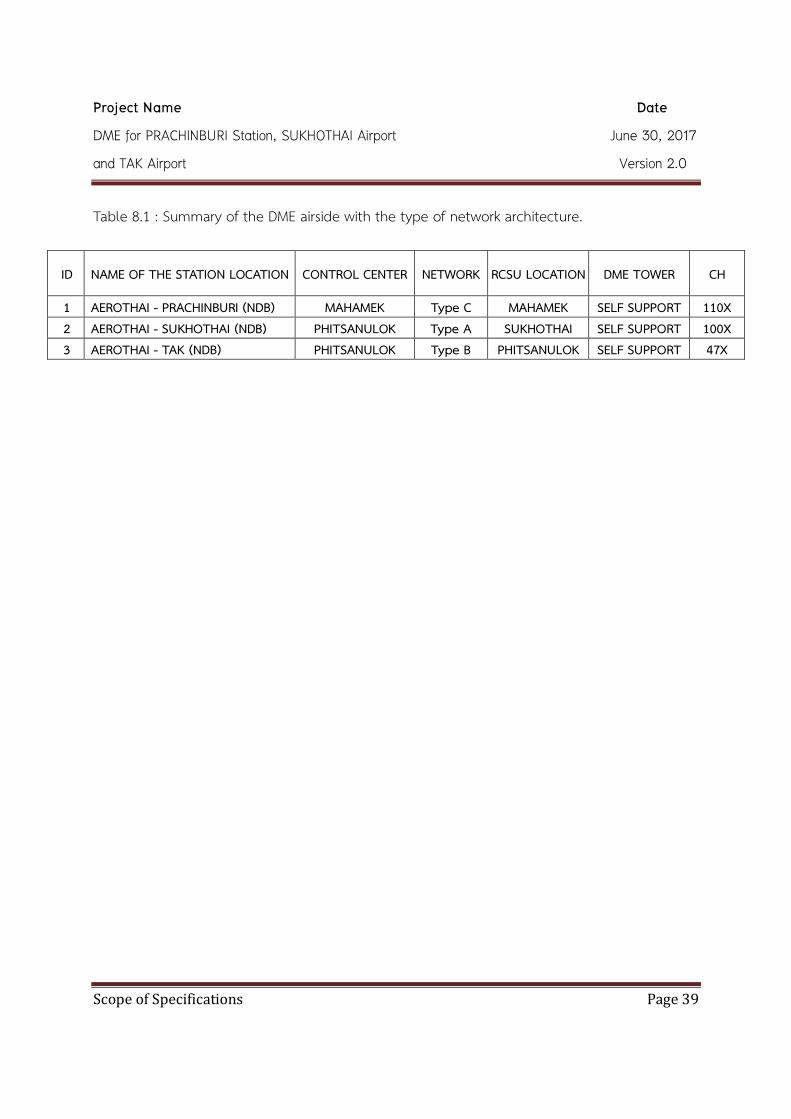
Table 8.1 : Summary of the DME airside with the type of network architecture.
ID NAME OF THE STATION LOCATION CONTROL CENTER NETWORK RCSU LOCATION DME TOWER CH
1 AEROTHAI - PRACHINBURI (NDB) MAHAMEK Type C MAHAMEK SELF SUPPORT 110X 2 AEROTHAI - SUKHOTHAI (NDB) PHITSANULOK Type A SUKHOTHAI SELF SUPPORT 100X 3 AEROTHAI - TAK (NDB) PHITSANULOK Type B PHITSANULOK SELF SUPPORT 47X

Project Name Date
DME for PRACHINBURI Station, SUKHOTHAI Airport June 30, 2017
and TAK Airport Version 2.0
Scope of Specifications Page 40
9. Requirements of Spare Parts The details of spare parts for each DME and UPS & STS equipment shall be complied with the following. 9.1 For each DME equipment, the spare parts of 100% shall be provided. Where 100%
means a complete set for single system configuration, e.g. line replaceable module (LRM), circuit card assembly (CCA), backplanes, and RF switches (coaxial relays), etc. For each DME equipment, one (1) sets of double LED obstruction light [3.3.5] shall also be provided as the spare parts.
9.2 Each RCSU of DME [5.2] and RSU of DME [5.3] shall be provided with the spare parts of 100%. Where 100% means one (1) complete unit of each line replaceable module (LRM), circuit card assembly (CCA) and backplanes, etc.
9.3 All spare parts related to UPS & STS equipment [4] are not required. It is AEROTHAI’s responsibility.
9.4 All spare parts related to network equipment [6] are not required. It is AEROTHAI’s responsibility.
9.5 The contractor shall take responsibility of WARRANTY the EXTRA spare parts (not included in 100% of AEROTHAI), when additional purchase, still compatible with the existing DME system for at least five (5) years. The agreement shall be complete when the contractor submit the confirmation document.

Project Name Date
DME for PRACHINBURI Station, SUKHOTHAI Airport June 30, 2017
and TAK Airport Version 2.0
Scope of Specifications Page 41
10. Supplements for Installation, Maintenance and System Calibration For installation, maintenance or else system calibration (both transmitter and monitor calibration), all relevant followings shall be provided : 10.1 Maintenance aids / accessories shall be provided.
10.1.1 If the manufacturer’s maintenance or calibration procedure is required : extension cards & cables, test cable or else related to each navigation aid equipment.
per DME
10.1.2 If the manufacturer’s maintenance or calibration procedure is required : directional coupler, phaser, dummy load and attenuation kits related to each navigation aid equipment.
per DME
10.2 Installation Materials and Tool kits shall be provided. 10.2.1 If the manufacturer’s installation procedure is required :
installation materials such as lines & cables, connectors, cable trays, cable ties and conduits.
per DME

Project Name Date
DME for PRACHINBURI Station, SUKHOTHAI Airport June 30, 2017
and TAK Airport Version 2.0
Scope of Specifications Page 42
11. Technical Documents and Test Reports [E] The contractor shall provide the following document :
11.1 After completion of Factory Acceptance Test (FAT) at the factory,
one (1) original and two (2) hard copies of FAT REPORT shall be provided. per DME
11.2 After completion of commissioning flight inspection and Site Acceptance
Test (SAT) at each DME, one (1) original and two (2) hard copies of SAT REPORT shall be provided.
per DME
11.3 Before installation, Three (3) sets of hard copy and one (1) set of CD/DVD (or any portable data storage devices), of EQUIPMENT MANUAL (including installation, operation and maintenance).
per DME
11.4 Before installation, Two (2) sets of hard copy and one (1) set of CD/DVD (or any portable data storage devices), of ASSEMBLY DRAWINGS & SCHEMATIC DIAGRAM
per DME
11.5 Before installation, Two (2) sets of hard copy and one (1) set of CD/DVD (or any portable data storage devices), of PART LISTS related to module/CCAs and components of the navigation aid equipment.
per DME

Project Name Date
DME for PRACHINBURI Station, SUKHOTHAI Airport June 30, 2017
and TAK Airport Version 2.0
Scope of Specifications Page 43
ABBREVIATIONS Abbreviations Full Name AEROTHAI Aeronautical Radio of Thailand Ltd. BITE Built-in Test Equipment CCA Circuit Card Assembly FAA Federal Aviation Administration ICAO International Civil Aviation Organization LCSU Local Control Status Unit LMM Local Maintenance Monitoring MTBF Mean Time Between Failure MTBO Mean Time Between Outage MTTR Mean Time to Repair RCSU Remote Control and Status Unit RMM Remote Maintenance Monitoring RSU Remote Status Unit SNMP Simple Network Management Protocol STS Static Transfer Switch UPS Uninterrupted Power Supply

Project Name Date
DME for PRACHINBURI Station, SUKHOTHAI Airport June 30, 2017
and TAK Airport Version 2.0
Scope of Specifications Page 44
APPENDIX A
LIST OF THE NEW DME STATION LOCATION
ID NAME OF THE STATION LOCATION LAND OWNER CONTROL CENTER Frequency /Channel Pairing DME (CH.)
(Reserved) (Reserved)
1 AEROTHAI - PRACHINBURI (NDB) RTA MAHAMEK 110X - - 2 AEROTHAI - SUKHOTHAI (NDB) BKK AIRWAYS PHITSANULOK 100X - - 3 AEROTHAI - TAK (NDB) TREASURY PHITSANULOK 47X - -

Project Name Date
DME for PRACHINBURI Station, SUKHOTHAI Airport June 30, 2017
and TAK Airport Version 2.0
Scope of Specifications Page 45
APPENDIX B
THE PROTECTED COVERAGE OF DME/N The protected coverage of DME/N shall be determined by using Figure C-20 of [ANNEX 10 / Vol. I / Attachment C / Paragraph 7.2.1]. The propagation loss for paths without obstructions uses the IF-77 propagation model with a 4/3 Earth radius which has been confirmed by measurements.
Figure C-20 of [ANNEX 10 / Vol. I / Attachment C / Paragraph 7.2.1].

Project Name Date
DME for PRACHINBURI Station, SUKHOTHAI Airport June 30, 2017
and TAK Airport Version 2.0
Scope of Specifications Page 46
The figure above is derived from Figure C-20 of [ANNEX 10 / Vol. I / Attachment C / Paragraph 7.2.1]. It describes about the achievable RF signal coverage of DME/N related to EIRP value of DME GND facility to achieve a power density of -89 dBW/m2 (at airborne receiver) as a function of height above and distance from the DME. The above figure is based on the following assumption, D.1 Antenna height +5 m (17 ft) AGL over flat terrain. D.2 Airborne receiver sensitivity -120 dBW D.3 Transmission line loss, mismatch loss,
antenna polar pattern variation with respect to an isotropic antenna.
+9 dB
D.4 Power density required at antenna -111 dBW Remark :
1. Minus 111 dBW at the antenna corresponds to minus 89 dBW/m2 at mid-band frequency.
2. The power density for the case of an isotropic antenna may be computed in the following manner :
π
λ
4log10
2
−= ad PP
where
dP = power density in 2/mdBW
aP = power at receiving point in dBW λ = wavelength in metres

Project Name Date
DME for PRACHINBURI Station, SUKHOTHAI Airport June 30, 2017
and TAK Airport Version 2.0
Scope of Specifications Page 47
SECTION 2 CIVIL WORK

Project Name Date
DME for PRACHINBURI Station, SUKHOTHAI Airport June 30, 2017
and TAK Airport Version 2.0
Scope of Specifications Page 48
รายละเอยดงานปรบปรงและแบบรป สถาน NDB เพอรองรบการตดตง DME
พร_อมรปแบบโครงสร_างเสารองรบสายอากาศ DME
ทeาอากาศยานสโขทย ทeาอากาศยานตาก สถานเครองชeวยการเดนอากาศอสระปราจนบร


![Flight-check Paper, Proceedings pp. 183-192 · L. Nelson Spohnheimer Spohnheimer Consulting ... ICAO’s 2002 Doc 8071 Manual on Testing [2] ... The 1972 version of Doc 8071 allowed](https://static.fdocuments.us/doc/165x107/5b455b357f8b9ad1138b9e06/flight-check-paper-proceedings-pp-183-l-nelson-spohnheimer-spohnheimer-consulting.jpg)