SCION tC 2014 FOG LIGHT KIT - Sparks...
16
SCION tC 2014 FOG LIGHT KIT Page 1 of 16 Issue B : 01/08/14 Part #: PT413-21140 Conflicts: P/N PTR11-21100 Lowering Springs (CA only) Kit Contents: Wire Ties Self-Tapping Screws Fog Lamp, Left and Right Side Wire Harness Switch Relay Fog Light Bezel, Left and Right Side Hardware Content Item# Quantity Reqd. Description 1 11 7.5 inch Wire Ties Black 2 6 #10-16 Hex Head Self-Tapping Screws 3 1 Switch 4 5 6 7 1 2 1 2 Relay Fog Light Bezel, Right and Left Wire Harness Fog Lamp, Right and Left Additional Items (may be required) Item# Quantity Reqd. Description Recommended Sequence of Application Item# Accessory Description 1 Fog Light Kit 2 v4 3 v5 4 Audio 1 2 3 4 5 6 7 General Applicability Recommended Tools Personal & Vehicle Protection Blankets Special Tools Hella Photometric Beam Setter (or equivalent) Panel Removal Tool Installation Tools Socket Wrench 10 mm Socket Socket Extension Torque Wrench Diagonal Cutters #2 Phillips Screwdriver 8 mm socket or nut driver Special Chemicals Legend STOP: Damage to the vehicle may occur. Do not proceed until pro- cess has been complied with. CAUTION: A process that must be carefully observed in order to reduce the risk of damage to the accessory/vehicle. OPERATOR SAFETY: Use caution to avoid risk of injury. TOOLS & EQUIPMENT: Used in Figures to call out the specific tools and equipment recommended for the process. REVISION MARK: This mark highlights a change in installation with respect to previous issue. SAFETY TORQUE: This mark indicates that torque is related to safety. VIDEO: Video Available; click to Play Capable of measuring 5.4 N·m (48 in·lbs)
Transcript of SCION tC 2014 FOG LIGHT KIT - Sparks...

SCION tC 2014 FOGLIGHTKIT
Page 1 of 16Issue B : 01/08/14
Part#:PT413-21140Conflicts:P/NPTR11-21100LoweringSprings(CAonly)
KitContents:
Wire TiesSelf-Tapping
ScrewsFog Lamp,
Left and Right SideWire HarnessSwitch RelayFog Light Bezel,
Left and Right Side
HardwareContent
Item# QuantityReqd.
Description
1 11 7.5inchWireTiesBlack
2 6 #10-16HexHeadSelf-TappingScrews
3 1 Switch
4567
1212
RelayFogLightBezel,RightandLeftWireHarnessFogLamp,RightandLeft
AdditionalItems(may be required)
Item# QuantityReqd.
Description
RecommendedSequenceofApplication
Item# Accessory Description
1 FogLightKit
2 v4
3 v5
4 Audio
x1
1 2 3 4 5 6 7GeneralApplicability
RecommendedTools
Personal&VehicleProtection
Blankets
SpecialTools
Hella Photometric Beam Setter (or equivalent)
Panel Removal Tool
InstallationTools
Socket Wrench
10 mm Socket
Socket ExtensionTorque Wrench
Diagonal Cutters
#2 Phillips Screwdriver
8 mm socket or nut driver
SpecialChemicals
LegendSTOP:Damage to the vehicle may occur. Do not proceed until pro-cess has been complied with.
CAUTION: A process that must be carefully observed in order to reduce the risk of damage to the accessory/vehicle.
OPERATORSAFETY: Use caution to avoid risk of injury.
TOOLS&EQUIPMENT: Used in Figures to call out the specific tools and equipment recommended for the process.
REVISIONMARK: This mark highlights a change in installation with respect to previous issue.
SAFETYTORQUE: This mark indicates that torque is related to safety.
VIDEO: Video Available; click to Play
Capable of measuring 5.4 N·m (48 in·lbs)

SCION tC 2014 FOGLIGHTKIT
Page 2 of 16Issue B : 01/08/14
TableofContents
I. Preparation ............................................................................................................................................... 1-21. Table Of Contents..................................................................................................................................2
II. Procedure................................................................................................................................................3-151. Vehicle Preparation................................................................................................................................3
III. Accessory Function Checks .......................................................................................................................161. Vehicle Function Checks ......................................................................................................................16
AccessoryInstallationPractice(readbeforeinstallation)Care must be taken when installing this accessory to ensure damage does not occur to the vehicle. The installation of this accessory should follow approved guidelines to ensure a quality installation.
These guidelines can be found in the “Accessory Installation Practices” document.
This document covers such items as:• Vehicle Protection (use of
covers and blankets, cleaning chemicals, etc.)• Safety (eye protection, checking torque procedure, etc.)• Vehicle Disassembly/Reassembly (panel removal, part storage, etc.)• Electrical Component Disassembly/Reassembly (battery disconnection, connector removal, etc.)
Please see your Toyota/Scion/Lexus dealer for a copy of this document.

Page 3 of 16Issue B : 01/08/14
SCION tC 2014 FOGLIGHTKITProcedure
1. Precautions
a. Engine components and coolant may be hot,use caution.
2. CheckKitContents
a. Check kit for content and damage.
3. VehiclePreparation
a. Protect fender before starting.b. Remove battery cable from negative termi-
nal (Fig. 3-1).
CAUTION: Do not touch the positive terminal with any tool during removal.Fig. 3-1
Fig. 4-1
Fig. 4-2
10 mm SocketSocket WrenchExtension
Negative Lead
4. SwitchInstallation
a. With the aid of a panel removal tool,detach mirror control panel (Fig. 4-1).
b. Disconnect connectors.c. Remove right knock out from this panel
(Fig. 4-2).

Panel Removal Tool
Page 4 of 16Issue B : 01/08/14
SCION tC 2014 FOGLIGHTKITProcedure
d. Find 4 pin connector inside of instrumentpanel and remove electrical tape (Fig. 4-3).
Fig. 5-1
e. Install switch by pushing it into the openingin the mirror control panel (Fig. 4-4a).
CAUTION: Make sure that the graphic is in the indicated orientation (Fig. 4-4b).f. Reconnect mirror, dimmer, and fog light
switch.g. Reinstall mirror control panel.
5. RelayInstallation
a. Remove the head unit.
1. Disengage the five (5) clips and two (2)claws and then remove the instrumentcluster finish panel. Make sure to discon-nect the electrical harness at the top of thepanel (Fig. 5-1).
Fig. 4-3
Fig. 4-4a
Instrument ClusterFinish Panel
Clips (x3)
Clips (x2)
Claws (x2)
Switch orientation
Fig. 4-4b

Page 5 of 16Issue B : 01/08/14
SCION tC 2014 FOGLIGHTKITProcedure
Fig. 5-3
Fig. 5-2
2. Remove the four (4) bolts and the headunit (Fig. 5-2).
b. Disconnect all electrical connectors and an-tenna cable plug from the rear of the headunit (Fig. 5-3).
c. Remove the head unit from the vehicle.
d. Loosen the screw holding the relay bracket(Fig. 5-4).
Fig. 5-4
10 mm Socket, Socket Wrench, and Extension
10 mm Socket, Socket Wrench, and Extension
Head Unit
Bolts (x2) Bolts (x2)
Electrical Connectors (x4)
Antenna Cable Plug
Relay bracket screw

Panel Removal Tool
Page 6 of 16Issue B : 01/08/14
SCION tC 2014 FOGLIGHTKITProcedure
Fig. 6-2
e. Raise the bracket up and install the relayin middle port (Second port down from thetop, Fig. 5-5).
f. Reattach the relay bracket, reattach the wir-ing to the head unit, and then reinstall thehead unit.
g. Reassemble the dash panel (Fig. 5-1).
6. InstallationofWireHarness
a. Remove the radiator cover (Fig. 6-1).
1. Using panel removal tool, remove six (6)attachment pins and two (2) bumpers.
Fig. 6-1
Remove radiator cover
2. Lay the harness over the top of the engine.Route the short end of the harness with the2-pin connector down through the openingnear the driver side of the battery (Fig. 6-2and Fig. 6-3 on Page 7).
Fig. 5-5
Install relay in middle port1
23

Page 7 of 16Issue B : 01/08/14
SCION tC 2014 FOGLIGHTKITProcedure
Fig. 6-3
Fig. 6-4
Coolant overflowHose
Battery retentionbracket
b. Route the harness as shown (Fig. 6-3).
c. Route the long end of the harness towards thepassenger side of the vehicle underneath thebattery retention bracket and coolantoverflow hose (Fig. 6-4).
d. Route the harness with the single-pincon-nector down beside battery (Fig. 6-5).
Fig. 6-5
Harness Route Down

Page 8 of 16Issue B : 01/08/14
SCION tC 2014 FOGLIGHTKITProcedure
Fig. 6-6
Fig. 6-7aFig. 6-7b
Fig. 6-8
Attach wire harness ringterminal with this screw.
Rear of headlight
Connector
Torque Wrench, 10 mm socket, and extension
e. Locate the vehicle single-pin black connec-tor behind the bumper, below and in front ofthe battery. Connect the fog light connectorto the vehicles’ single-pin black connector(Fig 6-6).
1. Breakaway tape may need to be removedfrom the connector before use.
f. Locate the single-pin harness connector(vehicle side connector may be black(Fig. 6-7a).
g. Plug in the harness as shown (Fig. 6-7b).
h. Locate the grounding screw near the battery.Remove the screw, add the wire harness ringterminal (ground) and reinstall the screwthrough both terminals (Fig. 6-8).
i. Tighten to 5.4N·m(48in·lbs).
Single-pin connectorlocation, behind bumper
Page 9 of 16Issue B : 01/08/14
SCION tC 2014 FOGLIGHTKITProcedure
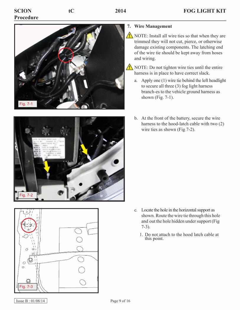
7. WireManagement
NOTE: Install all wire ties so that when they aretrimmed they will not cut, pierce, or otherwisedamage existing components. The latching endof the wire tie should be kept away from hosesand wiring.
NOTE: Do not tighten wire ties until the entireharness is in place to have correct slack.a. Apply one (1) wire tie behind the left headlight
to secure all three (3) fog light harnessbranch-es to the vehicle ground harness asshown (Fig. 7-1).
b. At the front of the battery, secure the wireharness to the hood-latch cable with two (2)wire ties as shown (Fig 7-2).
c. Locate the hole in the horizontal support asshown. Route the wire tie through this holeand out the hole hidden under support (Fig7-3).
1. Do not attach to the hood latch cable atthis point.
Fig. 7-1
Fig. 7-2
Fig. 7-3

Page 10 of 16Issue B : 01/08/14
SCION tC 2014 FOGLIGHTKITProcedure
Fig. 8-7
Fig. 7-4
Fig. 7-5
Fig. 7-7
Fig. 7-6
Hidden HoleWire TieFig. 7-3
Latch Wire Tie
d. Loop the wire tie through one opening in thehood latch bracket and secure wire harness(Fig. 7-4 and Fig. 7-5).
e. Use the visible and hidden holes in thehori-zontal support to secure the wireharness (Fig. 7-4).
f. Locate the hole in vertical surface of sup-port, under the coolant overflow hose. Se-cure the wire harness to this hole (Fig. 7-6).
1. Keep the harness under the horizontal sup-port.
g. Locate the hole in vertical support. Securethe wire harness to this hole (Fig. 7-7).
F
F
G
G
D
D
E

Engine under-cover
Page 11 of 16Issue B : 01/08/14
SCION tC 2014 FOGLIGHTKITProcedure
Fig. 7-9a
Fig. 7-9b
Panel Removal Tool
Diagonal Cutters
Fig. 7-8
i. Locate the corrugated tubing under thepassen-ger side headlight wire harness (Fig.7-9a).
1. Do not attach anything to the airbag wireharness (Fig. 7-9b).
CAUTION: Verify there is enough length on the passenger side to connect to fog light. Adjust harness if necessary.j. Tighten all wire ties.
1. Cut off all excess wire ties. Keep sharpends to a minimum.
k. Reinstall the radiator cover removed inStep 6(a) (Fig. 6-1).
8. ExteriorPartsRemoval
a. Raise the vehicle.b. Remove the engine under-cover by
remov-ing the ten (10) fasteners that arecircled (Fig. 8-1).
1. Save all screws, clips, and the under-cover.
h. Route the remaining 2-pin connector throughthe opening under the passenger (vehicleright) side headlight (Fig 7-8).
Fig. 8-1
Airbag harness, do not attach anything to this wire

Fig. 9-1
Page 12 of 16Issue B : 01/08/14
SCION tC 2014 FOGLIGHTKITProcedure
Fig. 8-3
Fig. 8-4
c. Remove the two (2) screws and one (1)snap-fastener circled from fender liner(Fig. 8-2).
d. Repeat for other side of vehicle.
1. Remove one (1) fastener from the foglight filler plate located behind the bum-per cover (Fig. 8-3).
#2 Phillips Screwdriver
e. Push the bezel out from the rear (Fig. 8-4).
10 mm Socket, Socket Wrench, and Panel Removal Tool
Fig. 8-2

Page 13 of 16Issue B : 01/08/14
SCION tC 2014 FOGLIGHTKITProcedure
9. AssembleFogLight
a. Assemble the left and right fog lights.b. Bezels are marked for installation on the
left and right side of the vehicle (Fig. 9-1).
c. Secure the lamp to bezel.
1. Install the lamps by inserting them fromthe rear of the bezel (Fig. 9-2).
2. Use three (3) #10-16 hex head self-tapping screws to fasten the lamp to thebezel.
CAUTION: Lamps are marked RIGHT and LEFT and will not fit if reversed.
Fig. 9-1
Fig. 9-2
Left “L”Right “R”
R
8 mm Nut driver
Fig. 10-1
#2 Phillips Screwdriver10. SecureFogLightAssemblytovehicle.
a. Reinstall the lamp and bezel in the bumpercover. Make sure all bezel clips engageproperly (Fig. 10-1).
CAUTION: Do not overtighten the screw, do not use power tools.b. Connect the harness to the lamp.c. Repeat for the other side of the vehicle.

Page 14 of 16Issue B : 01/08/14
SCION tC 2014 FOGLIGHTKITProcedure
Fig. 11-1 Engine under-cover
Left Side
Right Side
d. Secure the left side harness using two (2)wire ties to secure the harness as indicatedby the circles (Fig. 10-2).
e. Locate the mounting hole on the windshieldwasher fluid reservoir above and behind thepassenger side fog lamp. Use one (1) wiretie to secure the harness to this mountinghole (Fig 10-3).
f. Trim off all excess from wire ties. Keep sharpends to a minimum.
11. Reassembly
a. Reinstall the engine under-cover (Fig. 11-1).
NOTE: If this is a DIO installation, wait until the end of installation, after aiming (Step 12).b. Reinstall the ten (10) fasteners securing he
the engine under-cover in locations that arecircled.
Fig. 10-2
Fig. 10-3
10 mm Socket, Socket Wrench, and Panel Removal Tool
Diagonal Cutters
Diagonal Cutters

Page 15 of 16Issue B : 01/08/14
SCION tC 2014 FOGLIGHTKITProcedure
Fig. 12-2
c. Reinstall the two (2) screws and one (1)snap-fastener circled from fender liner(Fig. 11-2).
1. Repeat for other side of vehicle.
d. Lower the vehicle.e. Reconnect the battery negative cable.
f. Tighten to 5.4N·m(48in·lbs).
CAUTION: Do not touch the positive terminal with any tool during replacement.
Fig. 12-1
Fig. 11-2
12. AimingInstructions(DIOOnly)
a. Position the vehicle on a flat surface at adistance of 25 feet (7.6m) from the foglight to a wall (Fig. 12-1).
1. Measure the distance from the center ofthe lamp to the ground and mark off thesame height on the wall. This is your foglight centerline.
2. Adjustment of the fog lights is done byturning the adjustment screw using aPhillips screwdriver.
3. Turn on the fog lights and adjust them sothat the top of the beam (high intensityportion) falls 4 inches (102 mm) belowthe mark on the wall (fog light center-line).
b. Alternate aiming method: Use Hella Pho-tometric Beam Setter (or equivalent) tocorrectly align fog light beam (Fig 12-2).
c. Reinstall the vehicle under-cover followingStep 11a on Page 14
10 mm Socket, Torque Wrench, and Phillips screwdriver

FOGLIGHTKITSCION tC 2014 CHECKLIST–these points MUSTbe checked to ensure a quality installation.
Page 16 of 16Issue B : 01/08/14
1
Whattodo.
Function Function
Major Action Checks
Turn on headlights
AccessoryFunctionChecks
VehicleFunctionCheck
VehicleAppearanceCheck
Headlights “ON”
Turn on fog lights Fog lights “ON”
Fog lights are not “ON” with headlights “OFF”
Lamp symbol is facing left
High beams “ON” / Fog lights “OFF”
Low beams “ON” / Fog lights “ON”
Battery negative cable: 5.4N·m(48in·lbs)
Turn off headlights
Check fog light switch orientation
Switch on high beams
Check dashboard lights
Inspect bolt torque
Check taillights.
Verify fit of fog lamps
Check reverse lights.
Check brake lights.
Verify fit of bezels
Check emergency flashers.
Check turn signals.
Verify fit of switch
Check mirror controls.
Check battery terminals for tightness with 10 mm socket and torque wrench.
After accessory installation and removal of protective cover(s), perform a visual inspection of the vehicle
Check Radio.
Ensure no damage (including scuffs and scratches) was caused during the installation process.
(For PPO installations, refer to TMS Accessory Quality Shipping Standard.)
Whattolookfor.
2
3
4
5
6
7
101906
Stamp