Scientific background to the harmonization of structural ...heronjournal.nl/50-4/3.pdf ·...
17
Scientific background to the harmonization of structural Eurocodes Joël Kruppa CTICM, Paris, France Daniel Joyeux CTICM, Paris, France Bin Zhao CTICM, Paris, France Structural Eurocodes are a set of 58 different parts dealing with all the aspects of the design of buildings and civil works. Among them are some parts devoted to the structural fire design. This paper gives some background information from various research projects which were carried out during the last decade to improve or fill some gaps in the knowledge to be able to understand the entire structural behaviour of a building when submitted to a real fire. Focus is made on the so called ‘natural fire safety concept’ and on projects dealing with composite (steel + concrete) structures, as well as steel members. Key words: Structural Eurocodes, fire design, natural fire, fire safety engineering, heat transfer, mechanical behaviour, modelling 1 Introduction The Eurocodes are a series of European standards which provide a common series of methods for calculating the mechanical strength of elements playing a structural role in construction works (hereinafter ‘structural construction products’). Those methods make it possible to design construction works, to check the stability of construction works or parts thereof and to give the necessary dimensions of structural construction products [1]. The Eurocodes provide common design methods, expressed in a set of European standards, which are intended to be used as reference documents for Member States to [2]: • prove the compliance of building and civil engineering works or parts thereof with Essential Requirement n°1 Mechanical resistance and stability (including aspects of Essential Requirement n°4 Safety in use, which relate to mechanical resistance and stability) and a part of Essential Requirement n°2 Safety in case of fire, including durability, as defined in Annex 1 of the Construction Product Directive 219 HERON, Vol. 50, No 4 (2005)
Transcript of Scientific background to the harmonization of structural ...heronjournal.nl/50-4/3.pdf ·...

Scientific background to theharmonization of structural EurocodesJoël Kruppa
CTICM, Paris, France
Daniel Joyeux
CTICM, Paris, France
Bin Zhao
CTICM, Paris, France
Structural Eurocodes are a set of 58 different parts dealing with all the aspects of the design of
buildings and civil works. Among them are some parts devoted to the structural fire design.
This paper gives some background information from various research projects which were carried
out during the last decade to improve or fill some gaps in the knowledge to be able to understand
the entire structural behaviour of a building when submitted to a real fire. Focus is made on the
so called ‘natural fire safety concept’ and on projects dealing with composite (steel + concrete)
structures, as well as steel members.
Key words: Structural Eurocodes, fire design, natural fire, fire safety engineering, heat transfer,
mechanical behaviour, modelling
1 Introduction
The Eurocodes are a series of European standards which provide a common series of methods
for calculating the mechanical strength of elements playing a structural role in construction
works (hereinafter ‘structural construction products’). Those methods make it possible to
design construction works, to check the stability of construction works or parts thereof and
to give the necessary dimensions of structural construction products [1].
The Eurocodes provide common design methods, expressed in a set of European standards,
which are intended to be used as reference documents for Member States to [2]:
• prove the compliance of building and civil engineering works or parts thereof with Essential
Requirement n°1 Mechanical resistance and stability (including aspects of Essential Requirement
n°4 Safety in use, which relate to mechanical resistance and stability) and a part of Essential
Requirement n°2 Safety in case of fire, including durability, as defined in Annex 1 of the
Construction Product Directive
219HERON, Vol. 50, No 4 (2005)
HERON 60898 28 09-08-2006 20:32 Pagina 219

• express in technical terms these Essential Requirements applicable to the works and parts
thereof
• determine the performance of structural components and kits with regard to mechanical
resistance and stability and resistance to fire, insofar as it is part of the information
accompanying CE marking (e.g. declared values).
In the end of 2004, the 58 different parts which formed the Eurocode set are all nearly reaching
the stage of EN (European Norm) and will be implemented, as wished by the European
Commission and the Members States, within some years throughout the European Union,
the Economic European Area and, also, in a lot of other countries. Among these parts, 7 dealt
with ‘structural fire design’.
As far as these ‘fire parts’ of Eurocodes are concerned, to reach this stage, a huge amount
of work, involving many European research institutes and experts, was needed. Generally
based on existing recommendations developed, for instance, by European Commission for
Constructional Steelworks (ECCS), Fédération Européenne du Béton (FEB), Fédération
International de la Précontrainte (FIP)… the European Commission have set a group of 13
experts [3] in 1988 to write the first drafts of Eurocode fire parts.
In mid-1990 a series of parts dealing with actions on structures exposed to fire and with fire
resistance design of structures made in concrete, steel, composite and timber were officially
presented in a seminar on 25 to 27 June 1990 in Luxemburg to the potential users.
At this time, the European Commission took the decision to forward the further development
of these Structural Eurocodes to the Comité Européen de Normalisation (CEN) and in
1993-1995, new versions of these fire parts were issued, under the reference ENV 1991-2.2
to ENV 1999-1.2 [4, 5].
These ‘pre-standards’ were used in some European countries and decision was taken, at
the end of the 90’s to convert them to ‘full European standards’, leading now to the series
of EN1992-1.2 to EN 1999-1.2.
To illustrate the progress made in each version, table 1 presents the content of the annexes
of the various versions of Eurocode 1 on actions in case of fire, from 1990 to 2002.
The current final version of the Eurocode fire parts are given a wide range of tools for
designing entire structures or parts thereof for any kind of fire scenario. These tools can
be very simple when based on tabulated data, user friendly when based on analytical
formulae or very efficient when based on advanced calculation method such as the finite
element method at elevated temperatures.
220
HERON 60898 28 09-08-2006 20:32 Pagina 220

Table 1. Comparison of the content of annexes of Eurocode 1- 1.2
Hereafter, some examples are given of research projects carried out, showing the output they
have provided. They dealt with:
a. Natural fire safety concept to provide in-depth background information for assessment
of the behaviour of either large structural volume or car park structures when submitted
to real fire development
b. Fire design of steel structures either made with stainless steel or lightweight structural
elements
c. Fire design of composite structures either for beams or slabs.
2 Natural Fire Modelling
When dealing with realistic fire scenarios, the fire safety design is based on physically determined
thermal actions. In contrast with conventional fire design, parameters like the amount of fire
load, the rate of heat release and the ventilation factor play an important role in the fire design.
The specification of appropriate and realistic design fire scenarios is a crucial aspect of fire
safety design. The assumptions made with regard to these factors have a major influence on
the thermal conditions within a compartment and have a significant impact on the fire design.
The design fire scenarios used for the analysis/development of a building fire have to be
deduced from all the possible fire scenarios. In most buildings, the number of possible fire
scenarios is infinite and need to be reduced. Only ‘credible worst case fire scenarios’ will be
studied. If the design fire scenarios are chosen, a number of fire models are available to
calculate the thermal actions.
Item “Chapter 20” – 1990 “ENV 1991-2.2” - 1995 “EN 1991-1.2” – 2002
Fire load density 5 pages in annexes 0 5 pages – annex D 7 pages – annex Eand 3
Fire modelling 4 pages in annexes 1 None 2 pages – annex Dand 2
Parametric fires None 3 pages – annexes A 3 pages – annex Aand B
Equivalent time of 1 page – annex 5 2 pages – annex E 2 pages – annex Ffire exposure
Thermal actions for 6 pages – annex 6 8 pages – annex C 9 pages – annex Bexternal members
Localised fires none none 3 pages – annex C
221
HERON 60898 28 09-08-2006 20:32 Pagina 221
Different characteristics relevant for the assessment of design fires are listed by a working group
led by Leen Twilt et al [27]. Regarding the methods for assessing the fire severity, different
levels of fire calculation methods are relevant to the various stages of fire development. When a
fire is initiated, it is localised within a compartment and, according to the characteristics of the
compartment and of the fire load, it can remain localised or becomes generalised to the whole
compartment.
In many cases of small compartments or small opening regarding the compartment size, the fire
develops into to a fuly developed fire.
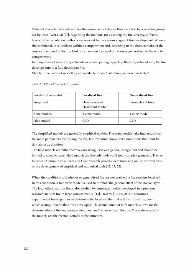
Mainly three levels of modelling are available for each situation, as shown in table 2.
Table 2. Different levels of fire models
The simplified models are generally empirical models. The zone-models take into account all
the main parameters controlling the fire, but introduce simplified assumptions that limit the
domain of application.
The field models are rather complex for being used as a general design tool and should be
limited to specific cases. Field models are the only tools valid for a complex geometry. The last
European Community of Steel and Coal research projects were focussing on the improvement
or the development of empirical and numerical tools [15, 17, 22].
When the conditions of flashover or generalised fire are not reached, a fire remains localised.
In this condition, a two-zone model is used to estimate the general effect of the smoke layer.
The local effect near the fire is also studied by empirical models developed in a previous
research ‘natural fire in large compartments’ [13]. Hasemi [18, 19, 20, 21] performed
experimental investigations to determine the localised thermal actions from a fire, from
which a simplified method was developed. The combination of both models allows for the
determination of the temperature field near and far away from the fire. The main results of
the models are the thermal actions to the structure.
Levels of the model Localised fire Generalised fire
Simplified Hasemi model Parametrical firesHeskestad model
Zone models 2-zone model 1-zone model
Filed model CFD CFD
222
HERON 60898 28 09-08-2006 20:32 Pagina 222
2.1 Hasemi model
In a research project devoted to large compartments [17], a calculation method was developed
to estimate the temperature field and the temperature of structural elements in case of a
localised fire. This method combines:
- Hasemi’s model for localised fire [18], and
- Two-zone model
These two models have been implemented within the software Ozone within a European
research project [15].
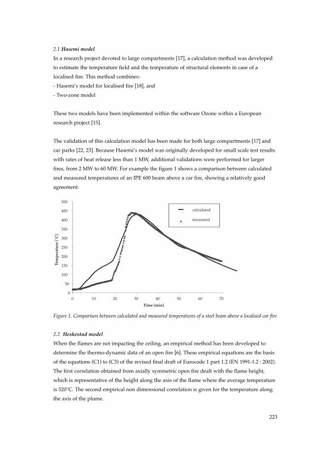
The validation of this calculation model has been made for both large compartments [17] and
car parks [22, 23]. Because Hasemi’s model was originally developed for small scale test results
with rates of heat release less than 1 MW, additional validations were performed for larger
fires, from 2 MW to 60 MW. For example the figure 1 shows a comparison between calculated
and measured temperatures of an IPE 600 beam above a car fire, showing a relatively good
agreement.
Figure 1. Comparison between calculated and measured temperatures of a steel beam above a localised car fire
2.2 Heskestad model
When the flames are not impacting the ceiling, an empirical method has been developed to
determine the thermo-dynamic data of an open fire [6]. These empirical equations are the basis
of the equations (C1) to (C3) of the revised final draft of Eurocode 1 part 1.2 (EN 1991-1.2 : 2002).
The first correlation obtained from axially symmetric open fire dealt with the flame height,
which is representative of the height along the axis of the flame where the average temperature
is 520°C. The second empirical non dimensional correlation is given for the temperature along
the axis of the plume.
Time [min]
Tem
per
atu
re [˚
C]
00
50
100
150
200
250
300
350
400
450
500
10 20 30 40 50 60 70
calculated
measured
223
HERON 60898 28 09-08-2006 20:32 Pagina 223

The application is not considered for low flame height to diameter ratio, where a single plume
does not exist. A limit of 0.5 for this ratio may be used.
Historically, these empirical equations have been developed from small scale test results.
Firstly, the determination of centreline temperature equation was determined to model the
plume, i.e. above the height of the flame. Further, several research works on small scale tests
(less than 1000 kW) [6, 7, 8 ,9 ,10] have been carried out to verify the previous equation but
also to extend their results to the flaming region. These researches have led to very similar
equations with similar values of the coefficients validated on the flaming regions. In addition,
these experiments have shown that the mean temperature along the axis of a turbulent open
fire is never higher than 900°C.
Then, European research projects have validated the equations for large fires. Large scale test
results have been used [14]. In figure 2 comparisons are made between measured and
calculated temperatures along the axis for a 20 MW fire performed in 1998 in a large industrial
hall [14, 22], and in one of the largest experimental test with temperature measurements with a
60MW fire performed in 1994 in an 28m high exhibition hall [11, 13].
Figure 2. Comparisons between centreline calculated and measured temperatures for a 60MW fire
(left) and a 20MW fire (right)
2.3 Parametrical fires
The parametric fires are relevant to the determination of temperature within a compartment in
case of generalized fire. However, even if it is a strong improvement compared to the standard
“ISO-fire”, these parametric fires, as shown in the following figures, are not yet able to provide
a very accurate answer of the fire severity, consequently it is recommended to use them only
for pre-design calculation. These parametrical fires presented in the ENV1991-2-2 have been
improved to include the multi-layer wall effect since they took into account only single layer
wall, limiting the application domain; the improved version has been implemented in the
EN1991-1-2 [28].
MeasuredHeskestadt
Height (m) Height (m)
Temperature (˚C) Temperature (˚C)
30
25
20
15
5
0
1614121086420
0 0200 200400 400600 600800 8001000 1000
MeasuredHeskestadt
224
HERON 60898 28 09-08-2006 20:32 Pagina 224

The second main improvement made for parametrical fires is the introduction of the fuel
control condition, by using minimum fire duration, generally assumed as 20 minutes.
This fuel control condition leads to a minimum value of O, the ventilation factor, calculated
from the 20 minutes fire duration. This allows withdrawing the case of high speed fire leading
to unsafe temperature.
The following figure shows the improvement for a fuel control fire, of a hotel fire test [40].
Figure 3. Effect of the improvement of the parametrical fires: comparison with experimental results
of a hotel fire test
2.4 Zone models
Two types of zone models exist:
• 1-zone model assuming a generalized fire
• 2 zone model assuming 2 layers: a hot upper zone and a cold lower zone.
A large number of zone-models exists in the world, the background of these models or the
code source are often not available [24, 25]. A zone model, OZONE, has been developed within
an ECSC research project [15]; it allows jumping from a two-zone model leading to a one-zone
model when hot gas layer reaches some specific conditions (of temperature and/or height).
This zone model was then validated by comparison with another existing one-zone model
(NAT [16]) and with more than 100 experimental tests.
Large scale fire tests have been performed and are used for validation. The figure 4 shows,
as example, the temperature-time curve comparison between tests and zone model.
225
HERON 60898 28 09-08-2006 20:32 Pagina 225

Figure 4. Comparison between calculated and measured temperatures of generalized fire in a school room
2.5 Characteristics of the fire compartment
2.5.1 Boundary elements of the compartment
One of the assumptions generally made is that the fire in one compartment will not spread
to other compartments. Whether this is true, depends on the fire behaviour of the boundary
constructions (floors, walls [including doors], etc.). Consequently, it is necessary to understand
this behaviour in order to assess their capability to act as fire barriers.
To carry out such assessment, the following options could be used:
• Calculations
Concerning some rather simple situations, it is possible to perform heat transfer and
mechanical behaviour calculations for the relevant time-temperature curve to be developed
within the compartment. Such an approach need to be, preliminary, correlated with some
existing test results on the same kind of separating element; however these test results
mainly refer to standard fire conditions, which not allows to a wide spread of knowledge
as far as the influence of the severity of fire on the behaviour of separating elements is
concerned. It is why this approach needs to be linked with “expert judgments”.
• Ad-hoc tests
The separating element can be exposed, in a furnace, to a temperature-time curve resulting
from a calculation with a fire model taken into account the parameters related to a
worst-case fire scenario. However the number of fire tests needed may be very large.
• Expert judgement
This approach makes use of the available test-data of ISO-resistance tests on separating
elements. In combination with calculation procedures, the behaviour under natural fire
conditions can be assessed by identifying the influence of the main parameters which
could lead to more onerous situations.
226
HERON 60898 28 09-08-2006 20:32 Pagina 226

• Direct use of ISO-requirements
National rules define fire compartments with ISO ratings for fire resistance of walls,
ceilings, doors and floors, depending on the use and the geometry of the building. Since
this kinds of requirements mean implicitly that a fire will not grow beyond the fire
compartment, it could be assumed that any separating element fulfilling these ISO
requirements will be able to maintain the fire within the compartment for any other fire
scenarios.
2.5.2 Thermal characteristics
The heat loss by convection, radiation and conduction from the compartment is an important
factor for the temperature determination. Through the separating element, according to the
thermal inertia of the wall (insulated or not), this heat loss is within the range of 30 % to 90%
of the total amount of heat released within the compartment by the combustion of fire load,
and consequently the thermal properties of the walls have to be known.
The three main parameters characterising the thermal properties of a material are:
- heat capacity cp
- density ρ
- conductivity λ
The conductivity and the heat capacity depend on temperature. It is suggested to neglect
the effect of water content since this will generally be on the safe side.
The table 3 gives the thermal characteristics of some materials, other than those already
covered by Eurocodes, usually used in building.
3 Fire behaviour of steel structures
For more than three decades, there was an enormous financial effort by the steel industry to
investigate the “weakness” of constructional steel structures subjected to fire and a number
of design rules have been developed in this field which were incorporated within Structural
Eurocodes. With respect to this situation, the recent research works have been orientated
towards other types of steel structures such as stainless steel structures as well as steel and
concrete composite structures. In addition, as far as local instability, for instance, the local
buckling of thin wall element, is concerned, very few works were performed before 90’s.
Consequently two research projects have been carried out on stainless steel [29, 30], in which
the fire behaviour of stainless steel members were investigated. It was known for many years
that stainless steel has a much better fire performance than carbon steel, nevertheless, no
systematic study was made to clarify the fire behaviour of stainless steel members used in
buildings. To provide a technical basis for fire design of stainless steel members both material
mechanical properties of different stainless steel grades and the related structural behaviour are
investigated not only through various experimental works but also from numerical simulations.
227
HERON 60898 28 09-08-2006 20:32 Pagina 227

Table 3. Typical values of the thermal properties of relevant materials for the compartment envelop
A huge number of tests have been carried out in order to investigate mechanical properties of
stainless steel at elevated temperatures (figure 5). Based on the experimental results obtained
for different steel grades, an analytical investigation was made which has led to the
establishment of a mathematical model for describing stress-strain relationships of stainless
steel at elevated temperatures.
The relevant parameters necessary to cover a temperature range from 20 °C to 1000 °C have
been given for five stainless steel grades studied in these research projects. The stainless steel
material model was then used to simulate the fire behaviour of various kinds of structural
elements; in general their comparison with test results gives good agreement [31] (figure 6).
The material model for stainless steel at elevated temperatures obtained in these projects has
been incorporated in the informative annex C of the fire part of Eurocode 3 for steel structures [32].
Material Temperature (°C) λ (W/m/K) ρ (kg/m3) cp (J/kg°K)
Ceramic Wool 20 0,035 128 800
200 0,06 128 900
500 0,12 128 1050
1000 0,27 128 1100
Cement 20 0,0483 200 751
250 0,0681 200 954
500 0,1128 200 1052
800 0,2016 200 1059
Calcium Silicate 20 0,0685 450 748
250 0,0786 450 956
450 0,0951 450 1060
Bricks 20 1,04 2000 1113
200 1,04 2000 1125
500 1,18 2000 1135
1000 1,41 2000 1164
228
HERON 60898 28 09-08-2006 20:32 Pagina 228

Device for tensile tests Anisothermal test results of stainless steel
Figure 5. Anisothermal test of stainless steel at elevated temperatures
Continuous stainless steel beam Stainless steel column
Figure 6. Comparison between fire tests of stainless structural members and numerical modelling
In parallel to above research projects on stainless steel, important works have been carried out
for investigating the fire behaviour of cold formed lightweight steel structures [33, 34, 35]
because of their increasing use not only as non-load bearing structural members, such as in fire
partition walls, but also as load bearing structural members such as in housing or rack
structures. The main objective of these works was to get deep information about the
performance of this type of steel structure subjected to fire condition. The main feature of such
structure elements is their important sensitivity to local buckling due to the very thin wall
sections, and in the ENV version of Eurocode 3, no calculation rule, except a fixed critical
temperature of 350 °C, is provided.
0
-20
-40
-60
-80
-100
-120
-140
-160
-1800 10
Left span
Calculation
Experience
Right span
Calculation
Experience
Calculation
ExperienceDisp V
Disp H
20 30 40
Defl
ecti
on (m
m)
Time (min)
45
40
35
30
25
20
15
10
5
0
-50 10 20 30
Dis
p. V
(mm
)
Time (min)
Load cell
908070605040302010
00 200 400 600 800 1000 1200
Rigid support
Str
ain
(%)
Temperature (˚C)
Furnace
Extensometer
Testspecimen
10%
30%
40%
50% - 2
70% - 1
70% - 3
90%
120%
20%
30% - 2
50% - 1
60%
70% - 2
80%
100%
229
HERON 60898 28 09-08-2006 20:32 Pagina 229

The research project dealt with the following items
• mechanical properties of cold worked lightweight steels at elevated temperature,
• assessment of the fire behaviour of fully engulfed lightweight steel studs,
• assessment of the fire behaviour of steel studs maintained by boards with fire on one
side of the partition,
• development of design rules to be implemented into the European standards.
The advanced numerical modelling developed in this research project, taking account of
corresponding material model, is fully valid for predicting the fire behaviour of cold worked
lightweight steel (figure 7). For the time being, the results of this work has been partially
included in informative annex E of the fire part of Eurocode 3 [32].
Deformed shape simulated for steel stud Deformed shape of studs in fire test
Figure 7. Comparison between fire tests of cold worked lightweight steel structural members and
numerical modelling with developed material model
4 Fire behaviour of composite structures
The steel and concrete composite structures have shown important advantages regarding the
fire performance. The first version of the fire part of Eurocode 4 appeared in the middle 80’s and
should be at that time the first code in the world in which a full design procedure is provided.
Although different design rules have been available in this version, some of them remained still
either incomplete or not fully accurate. For that reason, an important research project has been
conducted from 1988 in which the first design rules of Eurocode 4 with respect to steel and
concrete composite slabs and beams were fully investigated by means of both experimental
and analytical studies [36]. This project sponsored by ECSC, accompanied by other independent
works [37, 38], has led to improve design rules for composite slabs and beams.
230
HERON 60898 28 09-08-2006 20:32 Pagina 230

Regarding steel and concrete composite slabs, the design rules derived from above research
works allow to give much more accurate results compared to old design rules of the ENV
version of the fire part of Eurocode 4. For the insulation criterion, figure 8a a comparison is
made between the outcomes of the new simple calculation method and of an advanced
calculation model. A similar comparison, based on the rules given in the previous version
of the fire part of the Eurocode 4, is presented in figure 8b.
Figure 8. Comparison of simple calculation methods for the insulation criterion of composite slabs
to the outcomes of an advanced calculation model [37]
Another example concerns the temperature assessment of reinforcing steel in composite slabs;
in figure 9, one can find that the new rule gives better estimation than the old rules of Eurocode
4. All these rules and, in addition, the rules related to mechanical resistance model have been
incorporated in the latest version of the fire part of Eurocode 4.
Figure 9. Comparison of the simple calculation methods for temperature of reinforcing steels of
composite slabs to the outcomes of an advanced calculation model [37]
0.50
0.75
1.00
1.25
1.50
350 450 550 650 750
Temperature (adv. model)[
[°C] ==>
safe
unsafe
O
A α
1/2L3
u1HS
μ
σ
0.913
0.082
0.50
0.75
1.00
1.25
1.50
350 450 550 650 750
Temperature (adv. model) [°C] ==>
safe
unsafe
O
A α
1/2L3
u1HS
μ
σ
0.981
0.032
0.50
0.75
1.00
1.25
1.50
350 450 550 650 750
Temperature(EC4)
Temperature(adv.model)
[ -]==>
safe
unsafe
O
A α
1/2L3
u1HS
0.50
0.75
1.00
1.25
1.50
350 450 550 650 750
Temperature(new
rule)
Temperature(adv.model)
[-]==>
safe
unsafe
O
A α
1/2L3
u1HS
231
HERON 60898 28 09-08-2006 20:32 Pagina 231
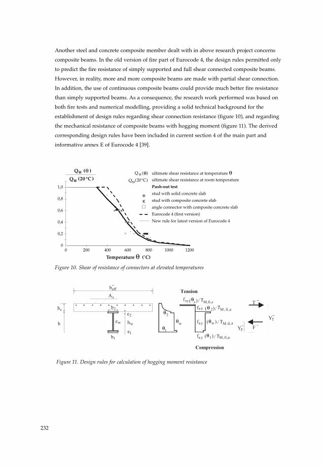
Another steel and concrete composite member dealt with in above research project concerns
composite beams. In the old version of fire part of Eurocode 4, the design rules permitted only
to predict the fire resistance of simply supported and full shear connected composite beams.
However, in reality, more and more composite beams are made with partial shear connection.
In addition, the use of continuous composite beams could provide much better fire resistance
than simply supported beams. As a consequence, the research work performed was based on
both fire tests and numerical modelling, providing a solid technical background for the
establishment of design rules regarding shear connection resistance (figure 10), and regarding
the mechanical resistance of composite beams with hogging moment (figure 11). The derived
corresponding design rules have been included in current section 4 of the main part and
informative annex E of Eurocode 4 [39].
Figure 10. Shear of resistance of connectors at elevated temperatures
Figure 11. Design rules for calculation of hogging moment resistance
−
θ
θθ
θ γ
θ γ
θ γ
θ γ
−
−
−
−
(20 °C )Qu (20°C)Qu
Q ( )θu Q ( )θu
1,0
0,8
0,6
0,4
0,2
00 200 400 600 800 1000
ultimate shear resistance at temperature θultimate shear resistance at room temperature
Push-out test
stud with solid concrete slab
stud with composite concrete slab
angle connector with composite concrete slab
Eurocode 4 (first version)
New rule for latest version of Eurocode 4
1200
Temperature θ (˚C)
232
HERON 60898 28 09-08-2006 20:32 Pagina 232

5 Conclusions
Over 15 years or so, a team of European experts were able to develop new calculation rules
for the behaviour of steel and composite structures in any fire situations.
These calculation rules were mainly based of a huge amount of research projects carried
out with the sponsoring the ECSC.
Within the last version of the fire part of Eurocode 1 “actions in case of fire”, it becomes
obvious that an accurate assessment of the fire safety level of a building needs to consider
realistic fire scenarios and that the use of the previous ISO-fire needs to be limited to the
ranking of construction products.
The design rules in the last version fire parts of Eurocode 3 and 4 become more accurate
and cover more types of structural members in fire situation due to the numerous research
projects carried out during last twenty years as presented above. Nevertheless, some work
is still necessary to enlarge the application field of Eurocodes for a full available fire safety
engineering assessment of steel and composite structures.
Acknowledgement
The authors wish to thank all the fire experts who have worked with enthusiasm and
abnegation to allow reaching the current stage of fire parts of Eurocodes and the European
Commission for having (and continuing to) sponsored a large amount of research projects.
References
[1] European Commission (11 December 2003) ‘the implementation and use of Eurocodes for
construction works and structural construction products’ in Commission Recommendation,
887/EC.
[2] European Commission (2003) ’Guidance Paper L (concerning the Construction Products
Directive)’ in Application and use of Eurocode, 89/106/EEC
[3] Dotreppe, J. C. ; C. Hahn, B. A. Haseltine, M. Kersken-Bradley, L. Krampf, J. Kruppa, M.
Law, J. Mathez, E. Pedersen, P. Schaumann, J. B. Schleich, G. Storti, L. Twilt (April 1990)
‘Actions on structures exposed to fire’ in Commission of European Communities, Eurocodes
Chapter 20.
[4] Kruppa, J. (5 December 1994) ‘Presentation of Eurocode parts on structural fire design’
in Symposium on fire standards in the international marketplace, Phoenix, Arizona.
[5] Kruppa, J. (24 – 26 September 1996) ‘Performance-based code in fire resistance : first attempt
by Eurocodes’ in International conference on performance-based codes and fire safety design
method, Ottawa, Canada.
[6] Audouin, L. and J.M Most (1995) ‘Average centreline temperatures of a buoyancy pool fire
by image processing of video recordings’ in Fire Safety Journal, Vol 24 n°2.
233
HERON 60898 28 09-08-2006 20:32 Pagina 233
[7] Heskestad, G. (September, 1988) ‘Fire plumes’ in Society of fire protection engineers (Eds) in
The handbook of Fire Protection engineering.
[8] Mac Caffrey, B.J. (1979) ‘Purely buoyant diffusion flames’ in NBSIR, 79-1910.
[9] Hasemi, H. and M. Nishita (1988) ‘Fuel shape effect on the deterministic properties of
turbulent flames’ in Fire safety science .
[10] Annarumma, M. (1989) ‘Modélisation numérique et validation expérimentale des flammes
de diffusion turbulentes dominées par les effets de gravité’, in Thèse de doctorat.
[11] Leborgne, H. Research Report n°94R-242, CTICM France.
[12] Leborgne, H. Research Report n°98R-406, CTICM France.
[13] Joyeux, D. (1995) ‘Simulation of the test of Parc des expositions de Versailles’, CTICM
France, INC-95/34-DJ/IM.
[14] Joyeux, D. (September 2001) ‘Validation of the Equations C1 to C3 of the annex C of
Eurocode 1 part 1.2’, CTICM France, INC – 01/303b – DJ/NB.
[15] Schleich, J_B.; L-G. and A-L. Cajot (1994-98) ‘Competitive steel buildings through natural
fire safety concept’ in Draft Final Report July 2000, Part 1 to 5, ECSC Research 7210-
SA/125,126,213,214,323,423,522,623,839,937, B-D-E-F-I-L-NL-UK & ECCS.
[16] Curtat, M. ; P. Fromy (mars 1992) ‘Prévision par le calcul des sollicitations thermiques dans
un local en feu. Première partie: le modèle et le logiciel NAT’ in Cahiers 2565 du CSTB.
[17] ARBED- LABEIN- TNO- CTICM – Université de Liège- (February 1997) ‘Development
of design rules for steel structures subjected to natural fires in Large Compartments’ in
Final report CEC Agreement 7210/ SA210, 317,517,618,832.
[18] Hasemi, Y. and T. Tokunaga (1984) ‘Flame Geometry Effects on the Buoyant Plumes from
Turbulent Diffusion Flames’ in Fire Science and Technology, Vol.4, n°1.
[19] Ptchelintsev, A.; Y. Hasemi and M. Nikolaenko (1995) ‘Numerical Analysis of Structures
exposed to localized Fire’ in ASIAFLAM’s 95, Hong Kong.
[20] Wakamatsu, T.; Y. Hasemi, Y. Yokobayashi, A. Ptchelintsev ‘Experimental Study on the
Heating Mechanism of a Steel Beam under Ceiling exposed to a localized Fire’.
[21] Hasemi, Y.; Y. Yokobayashi, T. Wakamatsu, A. Ptchelintsev (1995) ‘Fire Safety of Building
Components Exposed to a Localized Fire’ in ASIAFLAM’s 95, Hong Kong, Scope and
Experiments on Ceiling/Beam System Exposed to a Localized Fire.
[22] Joyeux, D. (March 2002) ‘demonstration tests in large compartment and car parks’ in
ECSC European research project, INC-02/410c-DJ/IM pp. 25 – CTICM - France.
[23] Joyeux, D. (March 2002) ‘Méthode simplifiée d’échauffement d’un élément soumis à un feu
localisé’ INC-00/62-DJ/IM – CTICM - France.
[24] DIFT - (22 July 1992) ARGOS Theory Manuel (draft 5), Danish Institute of Fire Technology.
[25] Peacock, Jones, Bukowski and Forney (June 1991) ‘Technical Reference Guide for the
Hazard I Fire Hazard Assessment Method’ in NIST Handbook 146, Volume II, Version 1.
[26] Quintiere, J.G. (21st -23rd August 1995) ‘Predicting fire growth’-‘First European Symposium
on Fire Safety Science’ Abstracts, Institute for Structural Engineering, CH - 8093 Zurich.
234
HERON 60898 28 09-08-2006 20:32 Pagina 234

[27] Twilt, L.; L.G. Cajot, D. Joyeux, P. Van de Leur, J. Kruppa, J.B. Schleich (March 1996) ‘Input
data for natural fire design of building structures’ in Proceedings IABSE conference Delft.
[28] CEN (2002) ‘Actions on Structures - Part 1.2 : Actions in case of fire’ in EN 1991-1.2,
Eurocode 1.
[29] CTICM/UGINE (March 2000) ‘Development of the Use of Stainless Steel in Construction,
WP 5.1: Material Behaviour at Elevated Temperatures’ in Final report, ECSC project 7210-
SA/327.
[30] CTICM/UGINE/VTT (December 2004) ‘Structural design of cold worked austenitic
stainless steel, WP6: Elevated temperatures’ in Final report, ECSC project n° 7210-PR/ 318.
[31] Zhao, B. and F. Conrad (May 2004) ‘Stress-strain relationships of stainless steel at elevated
temperatures’ in Proceedings of stainless steel experts seminar, London.
[32] CEN (2004) ‘Design of steel structures – Part 1-2: General rules – Structural fire design’ in
EN1993-1-2 Eurocode 3, Brussels.
[33] Outinen, J. (1995) ‘Transient state tensile results of structural steels S235, S355 and
S350GD+Z at elevated temperatures’, Helsinki University of Technology.
[34] Ranby, A. (February 1999) ‘Structural fire design of thin wall steel sections’ in PhD thesis,
Lulea University of Technology, Sweden.
[35] CTICM/ARBED/CORUS/LABEIN/SBI/VTT (March 2004) ‘Calculation rules of
lightweight steel sections in fire situation’ in Final report, ECSC project n° 7210-PR/ 254.
[36] CTICM/TNO (July 1995) ‘Fire Resistance of Composite Slabs with Profiled Steel Sheeting
and of Composite Steel Concrete Beams’.
[37] Both, C. (1998) ‘The Fire Resistance of Composites Steel-Concrete Slabs’
in Dissertation TU, Delft.
[38] Zhao, B. (July 1994) ‘Modélisation numérique des poutres et portiques mixtes acier-béton
avec glissements et grands déplacements - Résistance à l’incendie’ in PhD Thesis, INSA
de Rennes.
[39] CEN (2004) ‘Design of composite structures – Part 1-2: General rules – Structural fire
design’ in EN1994-1-2 Eurocode 4, Brussels.
[40] Joyeux, D. (July 1998) ‘Etude expérimentale de feux caractérisant un hôtel’
INC-98/24-JK/IM, CTICM – France.
235
HERON 60898 28 09-08-2006 20:32 Pagina 235