Science & Technology - DTIC
38
JPRS-CEN-92-007 23 JULY 1992 JPRS »10 Science & Technology CHINA: Energy REPRODUCED BY U.S. DEPARTMENT OF COMMERCE NATIONAL TECHNICAL INFORMATION SERVICE SPRINGFIELD, VA 22161
Transcript of Science & Technology - DTIC

JPRS-CEN-92-007 23 JULY 1992
JPRS »10
Science & Technology
CHINA: Energy
REPRODUCED BY
U.S. DEPARTMENT OF COMMERCE NATIONAL TECHNICAL INFORMATION SERVICE
SPRINGFIELD, VA 22161

Science & Technology China: Energy
JPRS-CEN-92-007 CONTENTS 23 July 1992
NATIONAL DEVELOPMENTS
State Council Approves 21 Large, Medium-Sized Power Projects [Zhang Chaowen, Wang Xianguang; RENMIN RIBAO, 19 Jun 92] ; 1
HYDROPOWER
Spending Up on Major Projects in Guangxi [GUANGXI RIBAO, 29 Mar 92] 2 Developing Sichuan's Mabian He Basin [Li Chengmao, Wei Wenhu; SICHUAN RIBAO, 18 May 92] ... 2
COAL
Addressing the Shortage of Coking Coal Resources [Dai Hewu, Xie Kebao, et al; MEITAN KEXUE JISHU, 25 Apr 92] 3
6.6 Billion Yuan Earmarked for Neimenggu Energy Development [Qu Zhenye; NEIMENGGU RIBAO, 18 Mar 92] 7
Chongxin Xinbai Coal Mine Under Construction [Xu Wei; GANSU RIBAO, 21 May 92] 8
OIL, GAS
OU Output Rises; New Fields Found [Yuan Zhou; CHINA DAILY, 8 Jul 92] 9 Big Breakthrough Reported in Tarim Petroleum Exploration
[Shen Zunjing; GANSU RIBAO, 5 May 92] : •• 9
NUCLEAR POWER
Fabrication Technology, Performance of HTGR Fuel Elements [Yang Youqing, Dai Shöuhui, et al.; HE DONGLIGONGCHENG, 10 Apr 92] 10
Coating Process for HTGR Particle Fuel [WangBaoshan, Mei Xiaohui, et al.; HE DONGLI GONGCHENG, 10 Apr 92] 18
Preparation of HTGR Fuel Kernels By Internal Gelation Process [Coo Xinsheng, WangFapin, et al; HE DONGLI GONGCHENG, 10 Apr 92] 23
CONSERVATION
Wang Yiping on Conservation, Comprehensive Use of Energy Resources [Wang Yiping; ZHONGGUO NENGYUAN, 25 May 92] , 30
Improving Enterprise Economic Benefits Through Energy Conservation [Li Junsheng; ZHONGGUO NENGYUAN, 25 May 92] •• 33

JPRS-CEN-92-007 23 July 1992 NATIONAL DEVELOPMENTS
State Council Approves 21 Large, Medium-Sized Power Projects 92P60358 Beijing RENMIN RIBAO in Chinese 19Jun92pl
[Article by Xinhua reporter Zhang Chaowen [1728 6389 2429] and correspondent Wang Xianguang [3769 7359 0342]
[Text] With the approval of the State Council, the State Planning Commission recently announced 21 large and medium-sized electric power capital construction projects.
Most of these projects will be completed either by the end of the Eighth 5-Year Plan or the beginning of the Ninth 5-Year Plan. After finishing all the construction, there will be an increase in installed capacity of 10.54 million kW. Total investment will be 21.9 billion yuan with more than 2.1 billion yuan in foreign capital. Among the 21 projects, 10, with an installed capacity of 8.11 million kW, will represent investment or joint investment schemes of the State Energy Investment Company. The Huaneng Corporation will have four projects with an installed capacity of 1.58 million kW. The remaining seven are local power projects with an installed capacity of 0.85 million kW.

HYDROPOWER JPRS-CEN-92-007
23 July 1992
Spending Up on Major Projects in Guangxi 926B0094B Naming GUANGXI RIBAO in Chinese 29 Mar 92 pi
[Excerpts] This year there are 25 key engineering projects in the Guangxi Autonomous Region, of which six are listed as key national construction projects for a total investment of up to 3.129 billion yuan, an increase of 1.228 billion over last year, or 64.S percent. The number of projects and total investment exceeds all previous years.
Projects designated as key national projects for this year include the Yantan hydropower station (including a 500 kV transmission line and transformer project), Tianshengqiao Basuo hydropower station (including a 500 kV transmission line and transformer project), and the Tianshengqiao first- cascade hydropower station. The ground work and facilities installation for the Tianshengqiao-Guizhou 500 kV trans- mission line are scheduled for completion this year. The Yantan hydropower station, Tianshengqiao second-cascade hydropower station, and the Tianhu hydropower in the Guilin area are all expected to reach partial operational status this year.
Developing Sichuan's Mabian He Basin 926B0094A Chengdu SICHUAN RIBAO in Chinese 18 May 92 pi [Article by reporters Li Chengmao [2621 2110 5399] and Wei Wenhu [7614 2429 0062]] [Excerpt] Construction of the main part of the Huangdan hydropower station, the start-up project for development of the Mabian He basin began on 15 April. This key power station is the only regulatory power station in the local power grid in southern Leshan Municipality, and when completed, it will be an impetus to the economic develop- ment ofthat area and Muchuan County. The 192-kilometer-long Mabian He basin, which passes through Mabian, Muchuan, and Qianwei counties, has a total fall of 1,890 meters and is ideally situated for energy development. In 1988, Leshan Municipality decided to undertake a systematic development of the Mabian He basin, and the plan was reviewed and received the support of the Provincial Committee and the Provincial Govern- ment. In October last year, the plan passed approval of the State Planning Commission and the building of Huangdan power station on the middle reaches of Mabian He was included as a key construction project in the provincial Eighth 5-Year Plan, for a total investment of nearly 200 million yuan, a total installed capacity of 45,000 kW, and an average annual power output of 204 million kWh. [passage omitted]

JPRS-CEN-92-007 23 July 1992 COAL
Addressing the Shortage of Coking Coal Resources 926B0095 Beijing MEITAN KEXUE JISHUfCOAL SCIENCE AND TECHNOLOGY] in Chinese No 4, 25 Apr 92 pp 44-48
[Article by Dai Hewu [2071 0735 2976], Xie Kebao [6200 0668 1405], and Chen Wenmin [7115 2429 2404] of the Central Coal Science Academy Beijing Coal Chemistry Institute: "A Discussion of Countermeasures for the Shortage of Strong Caking Coal"]
[Text] Strong caking coal [strongly-bonded coal 1730 4814 3561] is an important raw material for the refining of high-strength metallurgical coke. With the move toward larger scales and automation in iron smelting blast furnaces, the quality requirements for metallurgical coke have become increasingly strict and demand for strong caking coal has continued to increase. In all countries of the world, refining high-quality metallurgical coke is requiring more strong caking coal while development and production of strong caking coal have become increasingly difficult, which has formed an acute contradiction between supply and demand. Japan is the world's biggest importer of coking coal and has the strictest quality requirements. It imports over 60 million tons of coking coal a year, most of it with an ash content of 6 to 8 percent, from more than 40 coal mines in the United States, Canada, Australia, China, South Africa, and other countries. However, because of the difficulty in importing strong caking coal and the fact that it is an indispensable part of the coal mixture for coking, Kailuan in China has been forced to import rich coal with an ash content of as much as 11.5 percent after washing, which shows that buying strong caking coal in the world's coking coal market at present is not that easy. At the International Coal Dressing Conference held in Tokyo, Japan in October 1990, Japan proposed a new concept regarding coal dressing technologies of the future that called both for a reduction in the ash content of coal when it is dressed and for removal of the organic inert matter in coal at the same time to improve the bonding and fluidity of coal. From another perspective, this is a reflection of the desire and way to increase the bonded matter in coking coal.
Compared to other coal varieties, China has relatively limited strong caking coal resources, but the amount cannot be considered small at the present stage as far as the total amounts being extracted being able to satisfy the require- ments of the iron and steel industry are concerned. Because of irrational utilization and various other reasons, shortages have also appeared and the situation is especially acute in several large iron and steel companies, some of which have even been forced to import from foreign countries, and they imported 870,000 tons of coking coal in 1990. Shanghai's Baoshan Iron and Steel Complex, for example, imported strong caking coal from Australia. This is a full indication of the urgent need to do conscientious research on the devel- opment, production, transportation, allocation and other situations and problems for China's strong caking coal and on countermeasures that should be adopted. This cannot be ignored.
I. The Present and Future of Strong Caking Coal Shortages Acknowledging the resource preservation characteristics and production situation of China's strong caking coal and intensively analyzing the current situation and strong caking coal utilization needs will also aid in understanding the causes and problems of the shortage of strong caking coal, which in turn will aid in finding effective ways to reverse the shortage situation and better meet the requirements of national economic development and international trade.
A. Acknowledge that strong caking coal varieties account for a limited proportion of China's coking coal resources China's proven and available reserves of coking coal account for only about 30 percent of our total coal reserves, while strongly-bonded rich coal and coking coal account for just 3.7 percent and 5.0 percent, respectively, of our reserves, for a total of 8.7 percent, so they still account for less than one- tenth of China's coal resources. This shows that China's strong caking coal resources are rather limited and that we must soberly acknowledge that China is a country that has a shortage of strong caking coal resources.
As for the intensity of coking coal development, coking coal output was 512 million tons in 1990, equal to 45.71 percent of China's total coal output. This included outputs of 75.74 million tons of rich coal and 97.98 million tons of coking coal, equal to 14.77 percent and 19.11 percent, respectively, of our coking coal output, and the total for the two was 33.88 percent, which forms an overloaded extraction situa- tion. Despite the fact that extraction of strong caking coal is already overloaded, shortages still appear. As China's iron and steel industry continues to develop, if we fail to adopt effective measures and countermeasures, the shortages will continue to grow in the future.
B. The contradiction between strong caking coal production and the deployment of key iron and steel enterprises Most of China's key iron and steel enterprises are located in eastern China. They include Baoshan, Meishan, Ma'anshan, and Xinyu in east China, Anshan and Benxi in northeast China, Shoudu [Capital], Taiyuan, Tianjin, Xuanhua, and Baotou in northern China, as well as three key iron and steel enterprises in southwest China, two in central China, and one in northwest China. In contrast, China's strongly- bonded rich coal and coking coal is mainly produced in north China. With the exception of southwest China where coking coal output is slightly greater than demand, demand for rich coal and coking coal in excess of supply has appeared in all other large regions, which is an indication that large amounts of strong caking coal will have to be shipped out of north China, for as long as until the year 2020. It is hard to see any improvement in this contradic- tion between supply and demand.
Given this situation, we should also adopt effective mea- sures and differential treatment, divide blast furnaces according to capacity into three categories, greater than 1,000 mm3, 500 to 1,000 mm3, and smaller than 500 mm3, for selective supplies of coal, and try as hard as possible to

COAL JPRS-CEN-92-007
23 July 1992
supply low-ash and low-sulfur strong caking coal to the huge 4,000 mm3 blast furnace at Shanghai's Baoshan Iron and Steel Complex, while at the same time achieving coal supplies from local areas, fixed site supplies, superior prices for superior quality, and other principles to improve sup- plies of strong caking coal and guarantee smooth develop- ment of the iron and steel industry.
C. Not enough strong caking coal in the mixture has resulted in metallurgical coke that is not strong enough Utilization coefficients in China's blast furnaces are too low. This is related to the low quality of iron ore resources, low technical levels of smelting operations, coke quality, and other factors. The coke used at China's 18 key iron and steel enterprises is not strong enough and its (Migongzhua- ngu) index compared to similar enterprises in foreign coun- tries shows an Mm about 2 to 3 percent lower and M10 1 to 2 percent lower, which has a substantial impact on all operational indices of large blast furnaces. Increasing the proportion and quality of strong caking coal in the existing coal mixture has always been an urgent requirement of metallurgical departments. The amount of strong caking coal that is mixed in directly affects the coke strength indices. For example, the rich coal and coking coal used in the coal mixture at Anshan Iron and Steel Mill accounts for just 40 percent and the refined coke has a strength Mw of 73.2 percent and M,0 of 9.1 percent, and it is third-grade metallurgical coke. At the Capital Iron and Steel Complex, however, the coal loaded into the furnace is 52 percent rich coal and coking coal, and the refined coke has a strength of MJO of 78.0 percent and M,0 of 8.3 percent and is second- grade metallurgical coke. The coking coal used at most of China's key iron and steel enterprises is third-grade coke, while the Jiuquan and Shuicheng Iron and Steel Mills use substandard coke. Increasing and expanding the amount of rich coal and coking coal that is mixed in is one effective way to improve the strength of coke.
D. Development of indigenous coke production has expanded the shortage of strong caking coal It is common knowledge that most indigenous coking requires strong caking coal, has a low coke formation rate, and severely pollutes the environment. Although state plan- ning departments have ordered restrictions on the develop- ment of indigenous coking, indigenous coke output has increased, not decreased, every year since 1982.
It deserves special mention that the main indigenous coke producing regions are China's primary coking coal pro- ducing regions. In Shanxi Province, for example, indigenous coke output reached 9,593,200 tons in 1989, equal to 51 percent of China's indigenous coke. Indigenous coke output also exceeds 1.5 million tons in Sichuan, Guizhou, and Yunnan provinces, and indigenous coke output is between 500,000 tons and 1 million tons in Henan, Shandong, and Hebei provinces. Apparently, inconvenient transportation has resulted in large amounts of superior quality coking coal being dumped on the ground and becoming overstocked. This inexpensive resource advantage has been quickly inte- grated with surplus labor power in rural areas and in combination with small investments, simple technology,
quick startup, and good economic benefits has resulted in an inability to prohibit indigenous coke production and it has developed again. In terms of the waste of strong caking coal resources, however, this must be called a severe problem. Coking departments have indicated that the loss of coking coal, tar, coal gas, and so on due to indigenous coking each year exceeds 2 billion yuan, not counting expenditures in the environmental protection area. The coke formation rate in indigenous coking is only about 50 percent. Indigenous coking used 41.7 million tons of coking coal in 1990 and when estimated as using 50 percent strong caking coal, it consumed as much as 20.85 million tons of strong caking coal. It is apparent that the development of indigenous coking has resulted in serious shortages of strong caking coal.
FJ. Short-Tenn Countermeasures To Reduce the Shortage of Strong Caking Coal Supplies
Both short-term and long-term countermeasures to alleviate the shortage of strong caking coal cannot be separated from joint efforts by departments that produce and use coal. The necessary measures should be adopted in utilization tech- nology, policy coordination and control, prices and eco- nomics, and other areas before we can promote gradual rationalization of strong caking coal production, allocation, and utilization.
A. Ensure that all strong caking coal is washed, develop coal dressing technology for hard-to-wash high-sulfur coal, try to expand production of strong caking coal For a long time, the development of China's coal dressing industry has been unable to keep pace with the rate of growth in raw coal output, and the increase in washed and cleaned coal has been unable to meet the needs of the iron and steel and other industries, so accelerating development of China's coal dressing industry is essential. Expanding washed and cleaned coal production for strong caking coal is another urgent task.
We must ensure that all strong caking coal is washed. A substantial amount of the strong caking coal that China now produces still cannot be washed and there is a lack of coordination between coal dressing capacity and mine pro- duction. There is no way, for example, to wash all of the superior quality rich coal and coking coal from Liaoning's Hongyang Mining Region. Moreover, allocation, transpor- tation, circulation, and other factors have forced strong caking coal to be burned up as power coal. For this reason, ensuring that all strong caking coal is washed should be further affirmed as a fundamental policy and it should be more effectively implemented and adhered to.
There is still a substantial portion of China's strong caking coal that is hard-to-dress high-sulfur coal. If we deduct this portion from existing reserves and production, our strong caking coal resources are even smaller. Analysis of the average sulfur content of the coal from China's primary coking coal mines (Table 1) shows that with the exception of gas coal, which has an average sulfur content less than 1 percent at 0.78 percent, the average sulfur contents for China's coking coal are 2.33 percent for rich coal, 1.41 percent for coking coal, and 1.82 percent for lean coal, so the

JPRS-CEN-92-007 23 July 1992 COAL
average sulfur content is highest for rich coal. With the movement toward greater depths in mining regions of north China and east China and a rising proportion of Carbonif- erous Taiyuan system coal being developed, the proportion of high-sulfur coking coal will increase, so we urgently need to strengthen research and investments in hard-to-dress high-sulfur coal dressing technology and desulfurization methods, import advanced technology and equipment, try in every possible way to remove and reduce the sulfur
content of strong caking coal, and try to increase and expand our strong caking coal production capacity. At the same time, we must also do conscientious research on coordi- nated extraction and rational utilization of high-sulfur coal and, with a prerequisite of ensuring quality, effectively expand the utilization of high-sulfur coal. The sulfur content of China's metallurgical coke at present is significantly lower than in England, the former Soviet Union, Germany, and so on, which shows there is still considerable potential for using high-sulfur coal.
Table 1. Average Sulfur Content of Coal From China's Primary Coking Coal Mines Coal type Naader of coal samples Dry bate total salfar content StA (percent)
Average aaaaser Maxhnam valae Miaimam ralae
Weakly-bonded coal 139 1.20 5.81 0.08
Gas coal 534 0.78 10.24 0.10
Rich coal 249 2.33 8.56 0.11
Coking coal 295 1.41 6.38 0.09
Lean coal 175 1.82 7.22 0.15
B. Readjust the parity price for strong caking coal, apply economic levers to promote rational utilization of strong caking coal There is still no significant separation of price differences for coal varieties for the current parity prices for coal varieties and they must be readjustment. Table 2 lists the current parity prices for coal varieties.
Table 2. Current Parity Prices for Coking Coal Varieties Item Coking coal Rich coal 1/3 coking
coal Gas rich coal Gas coal Lean coal Poor lean
coal Jet coal,
coaL anthra- cite
Parity price (percent)
125 120 118 115 104 100 98 100
Table 2 shows that jet coal, unbonded coal, anthracite, and so on are usually called power coal and have a parity price of 100 percent. Among coking coal, however, coking coal and rich coal have the highest parity prices, with current parity prices of 123 percent and 120 percent. The parity price for strong caking coal relative to power coal is 1.23-1.20:1, so the parity price of strong caking coal is still too low. Internationally, the parity price of coking coal relative to power coal is generally 1.3-1.6:1. In light of this, we should use the fact that China has limited strong caking coal resources to raise the parity price for strong caking coal even more.
Moreover, the parity prices for the different varieties of coking coal also do not properly and accurately reflect the characteristics of China's coking coal variety resources and their effect on coke strength in the coking process. At present, lean coal has the lowest parity price among varieties of coking coal, but lean coal accounts for less than S percent of China's coking coal resources, so it is apparent that this is extremely unfavorable for utilization of our limited lean coal resources. Because rich coal and coking coal play the dominant role in bonding during the coking process, they are the main factor that determines the strength of coke. At present we still have not found inexpensive materials and methods to replace rich coal and coking coal. In other
words, modem chamber-type coking technology cannot do without rich coal and coking coal. Because of the greater amount of resources and good quality of other coal varieties and the ease of obtaining them, based on the principle that "the rareness of things makes them valuable", the parity price for coking coal and rich coal should be raised. After comprehensive research, I propose that the first step is to readjust die parity price to 132 percent to 140 percent. This would aid rational utilization of coking coal resources and protect our coking coal resources that are in short supply. We should apply the active role of economic levers to promote the development of coal extraction and dressing technology. At the same time, we should also try to develop tamped coke technology. It only uses 20 percent strong caking coal and 80 percent gas coal to make high- quality metallurgical coke and is widely used in Europe, but China has still not developed it. Several coking plants still place their hopes on larger supplies of strong caking coal, which obviously does not conform to China's national conditions.
C. Make major efforts to extend and develop blast furnace spray blowing technology, increase the amount of sprayed coal, reduce pressure on strong caking coal Blast furnace spray blowing refers to the spray blowing [injection] of pulverized coal into a blast furnace. It is an

COAL JPRS-CEN-92-007
23 July 1992
important way to reduce the coke ratio in iron smelting. Spray-blown pulverized coal can spray pulverized anthra- cite and pulverized bituminous coal, but China mainly sprays anthracite at present. Spray-blown pulverized coal reached about 2.8 million tons in 1988, which if calculated at a substitution ratio of 0.8 is equivalent to 2.24 million tons of coke. If this was coke that was being coked, it would take 1.435 million tons of washed and cleaned strong caking coal, which would be equivalent to conserving about 2.78 million tons of raw coal in coking strong caking coal. Metallurgical departments now plan to increase the amount of spray-blown pulverized coal per ton of iron from the present figure of 56 kg to 100 kg and to conduct oxygen-rich spray blowing experiments in an effort to increase the amount being spray blown to 150 to 200 kg or even higher. The amount of spray-blown pulverized coal at Japan's (Shenhu) Iron and Steel Mill has now reached 113.6 kg/ton of iron and (Xinri) Iron and Steel Mill will increase the amount of sprayed coal to 150 kg per ton. These facts provide full illustration that spray-blown pulverized coal is truly an effective way to reduce the coke ratio and reduce the amount of strong caking coal used, and there should be major efforts to extend and develop it. Moreover, coal production departments should also try to expand produc- tion of superior quality spray-blown coal and build a corre- sponding group of spray-blown coal production base areas to meet the needs of iron and steel departments.
D. Reinforce strong caking coal production and management, formulate regulations for strong caking coal utilization
To protect our limited and valuable strong caking coal resources and achieve planned and protective extraction, and to achieve controlled utilization of the strong caking coal that we produce, we should have a complementary set of management methods and measures like those the state has for gold, cigarettes, liquor, and other special materials to ensure the protection and effective utilization of strong caking coal resources.
First, conduct management in strict accordance with Article 15 in the "Mineral Resource Law". No unit or individual that has not received approval from the relevant adminis- trative departments of the State Council can extract strong caking coal. A system of issuing strong caking coal produc- tion licenses should be implemented. Township and town and other enterprises should restrict their extraction of this superior quality coal variety. Formulate the corresponding detailed management principles and severely punish viola- tors, and put a complete end to the situation of disorganized extraction and utilization of strong caking coal. In addition, special policies should be implemented for transportation of strong caking coal to guarantee preferential transportation and avoid restriction by railway circulation. Evidently, there is still some strong caking coal being produced that is not being put to good use because it was not transported on time or because of other problems. Of course, measures for stacking, storage, prevention of spontaneous combustion and oxidation, and so on for strong caking coal should keep pace to attain the goal of making the best use of strong caking coal.
III. Rely on Technical Progress, Strive To Develop New Technology, Explore New Ways To Solve the Shortage of Strong Caking Coal Because of the global shortage of strong caking coal, many countries are now actively exploring new methods and techniques for producing and replacing strong caking coal. Although they are not mature enough at present and the production costs are rather high, as the technology progresses and techniques are improved, it will not be impossible to overcome the difficulties and take a new path.
A. Develop new iron and steel smelting technology To stop using strong caking coal and coking coal in the future and transform traditional blast furnace iron smelting technology, all nations of the world are now trying to develop new iron and steel smelting technologies and they have made gratifying advances. Glenbrook Iron and Steel Mill in southern Auckland, New Zealand has adopted a steel smelting technology that uses subbituminous coal for direct reduction of iron ore sand to smelt iron. The subbituminous coal they are using is highly volatile jet coal with a water content of 18 to 22 percent, an ash content of 6 to 9 percent (dry base) and a maximum no greater than 12.5 percent, a volatile component of 43 to 49 percent (moisture-free and ash-free base) and a maximum of 53 percent, and a sulfur content no greater than 0.5 percent. The coal and refined iron ore (containing iron ore sand) are placed into a multi- layer bed vertical furnace. There are 12 layered beds in the furnace. The raw material is dried and preheated at the top of the furnace and passes through each of the layers until it reaches the bottom of the furnace. This releases its volatile components after being heated and a suitable amount of air is sprayed into each of the layered beds to cause part of the volatile components to be combusted and supply the heat required for the reaction within each of the layered beds. The excess volatile components are discharged with the exhaust gas and are resupplied to be burned for power generation. The temperature of the semi-coke and hot pure iron sand discharged from the multilayer bed vertical fur- nace is 650°C and it is transmitted to a rotating kiln 4.6 m in diameter and 65 m long with an operating temperature of 1100°C where it reacts for 3 hours and can produce 70 percent metallic iron. The discharge temperature is 950°C and it is loaded directly into a sealed tank and sent to an electric iron smelting furnace where it is smelted, producing pig iron and slag, and the pig iron and waste steel are then sent to an oxygen gas steel smelting stage. This plant has a steel production capacity of 700,000 tons/year and uses more than 850,000 tons of coal a year. The colored steel plate it produces sells very well. In addition, the United States Iron and Steel Society organized an expert survey in August 1987 which determined that the flow process for the next generation of iron and steel production would be direct smelting of steel. The coal and pre-reduced iron ore are reduced into high-carbon liquid iron and oxygen is then injected to reduce the liquid iron to the required carbon content. This technology has high productivity, requires litde equipment, and has a high adaptability to raw mate- rials. It can use non-coked coal and is flexible to operate. The United States Department of Energy has invested $23 million and the United States Iron and Steel Society has

JPRS-CEN-92-007 23 July 1992 COAL
invested $7 million to establish an intermediate testing plant near Pittsburgh that is expected to have 20 percent energy savings from iron ore to liquid steel and reduce production costs by 10 percent. The capital construction investment is SO percent less and the operating costs per ton of steel will be reduced $10 to $25. China's iron and steel research departments are actively developing a similar type of new iron and steel smelting technology. With the success and extension of new cokeless iron and steel smelting technology, there is a possibility that the shortage of strong caking coal may eventually be resolved.
B. Technology for producing man-made strong caking coal In developing coal liquefaction technology, it was discov- ered that when the depth of hydrogenization is not high, the liquid product obtained is in a solid state at normal temper- ature and has the characteristics of strong caking coal. The Central Coal Science Academy Beijing Coal Chemistry Institute has used moistureless and ashless base lignite from Shenbei with a volatile component content of 49 percent and bonding index of 0 that after hydrogenization and conversion can produce man-made rich coal with an ash content of just 0.3 percent, a volatile component content of 35 percent, and a bonding index of 93.80. The Ministry of Metallurgical Industry's Anshan Thermal Energy Institute has also developed man-made strong caking coal. Coal- mixing coking experiments in China and foreign countries have confirmed that this type of man-made rich coal plays an excellent role in improving the quality of metallurgical coke. While there are no major technical problems with this technology, the product costs are still very high. Computed at international prices, each ton of man-made rich coal is about 4 to 5 times higher in price than the international price of rich coal. Given its expense, it will be hard to extend and utilize in the coking industry in the short term. This type of product is also being explored as a raw material for fabricating acicular coke, carbon, and carbon fiber.
C. Exploring ways to convert non-coking coal to coking coal China has extremely rich non-coking coal resources that include several coal varieties with very low sulfur contents. The raw coal ash content in many coal seams is less than 8 percent. Its ash and sulfur indices are far superior to washed and cleaned coal for coking. If this type of coal were converted to a bonded type, it could be used for coal-mixed coking and its comprehensive utilization and economic value would be quite different.
Japan, Canada, England, India, and several other countries are actively exploring research on converting non-coking coal into coking coal. The exploratory experiments done by Canada's Energy Resources Institute have shown that the samples are maintained in a solid state from start to finish with a granularity of 2.38 to 4.76 mm, which is equivalent to
the granularity of the coal loaded into coking furnaces. Unbonded coal can undergo noncatalytic lightening and hydrogenization to achieve the effect of increased bonding. The conditions are 450°C, 13.9 MPa hydrogen pressure, and processing for 3 hours. The bonding of the coal can attain free expansion ranks ranging from 1 xk to 5 lh and one can observe under the microscope that it has anisotropic small spherical structures. This shows that for coal under solid state conditions, using certain chemical reactions and effects can achieve the fact of metamorphic conversion of all coal varieties formed under natural conditions to make coal varieties using artificially controlled conditions for con- verting all coal varieties and targeted processing. Of course, the depth of research is still far from sufficient, but still there are several indications that illustrate the technical feasibility.
6.6 Billion Yuan Earmarked for Neimenggu Energy Development 926B0089A Hohhot NEIMENGGU RIBAO in Chinese 18 Mar 92 pi
[Article by reporter Qu Zhenye [4234 2182 2814]] [Text] This year, national and local [sources] will put 6.6 billion yuan into construction for energy raw materials and processing in Neimenggu. This figure, 70 percent of the national investment in Neimenggu for the whole of the Seventh 5-Year Plan, heralds new heights for the develop- ment of an energy raw materials and processing base in the region. Neimenggu is rich in resources; ranking first in deposits for six rare earths, second in 10 varieties of coal, and fourth in timber reserves. In the early 50's, national investments for the first concentrated development of the Baotou steel industry and the Daxinganling forestry base were over 2 billion yuan. Thereafter, the national energy development strategy moved westward, and the 90's will be another golden era for large-scale development of Neimenggu. Last year, capital construction investments for Neimenggu totalled 5.8 billion yuan, the highest in history. There is a docket of large- and middle-sized projects on-going. There are the Jungar coal and power transmission projects, the large-scale mine con- struction and stripping facilities which have been ordered, and the first 100,000 kW generator that is expected to go into operation this year. It is less than 2 years since the Yuanbaoshan open pit mine was begun, preparations for concurrent construction and production are completed, and development continues apace. The Huolin He Nanlu open pit mine is nearing completion. The 3-billion-yuan Yimin He jointly managed coal and electricity project has formally entered its first phase of construction. Also listed among the key national projects for new construction and expansion are the Dongsheng coal field, and the Mada, Haibowan, Dayan, and Jalai Nur mining districts. When these coal projects are completed, extraction capacity could increase

COAL JPRS-CEN-92-007
23 July 1992
by 40.6 million metric tons. The Yuanbaoshan, Yimin He, and Fengzhen power plants will be expanded, and the total installed capacity could reach 3.1 million kW.
Construction of coal transportation arteries is also moving along smartly. Besides the four dedicated coal transporta- tion lines already built, the Tongliao Huolin He, Hailar Yiminhe, Baotou Shenlin, and Haibowan Gongwusu lines, the Jining south station on the Da(tong) Bao(tou) multi- track line and the automated marshalling facility are in full-scale construction; tracks are being laid for the Hailar segment of the Bin-Zhou multi-track line. Foreign funds amounting to 557 million yuan have been invested in China's longest local rail line, the Jining-Tongliao line, the super- and sub-structure construction for which are advancing simultaneously, and completion is expected next year. At that time, Neimenggu's precious black gold will be moving continuously toward northeast and north China over 2,851 kilometers of rail lines.
Chongxin Xinbai Coal Mine Under Construction 92P60352 Lanzhou GANSU RIBAO in Chinese 21 May 92 pi
[Article by reporter Xu Wei [6079 4850]]
[Text] Construction began recently on the Gansu Xinbai coal mine, a local key project of the Eighth 5-Year Plan. The mine is also listed by the China Local Coal Mines Corpora- tion as a national key mining region and major backbone mine. The mine is located in Chongxin County and has a geological reserve of 57.332 million tons and recoverable reserves of 39.92 million tons. Construction will take 42 months. After going into production, it can supply 450,000 tons of commercial coal yearly, which will not only strengthen the economy of Chongxin County and eastern Gansu, but will also be good for the Bao-Zhong Railroad's transportation business.

JPRS-CEN-92-007 23 July 1992 OIL, GAS
Oil Output Rises; New Fields Found 40100066 Beijing CHINA DAILY (Economics and Business) in English 8 Jul 92 p 2 [Article by staff reporter Yuan Zhou]
[Text] China's oil industry fulfilled its State production quota in the first 6 months of this year while making important new discoveries.
According to the China National Petroleum Corporation, which holds the monopoly over China's oil and natural gas production, crude oil output reached 68.75 million tons during the January-June period, accounting for half of this year's quota.
Meanwhile, the corporation's output of natural gas in the first 6 months was 7.S billion cubic metres, which is just over half of this years's target.
The corporation said, though, the oil industry had met difficulty in achieving a stable oil output from its aging oilfields. And efforts have been intensified to prevent a fall in production.
In the industry's resolve to produce more oil, 432 new wells have gone into operation since the beginning of this year.
Though the new oil discoveries were said to have been made in "main fields," the compnay did not elaborate on exact locations.
As the domestic demand for oil grows, China has been trying to ensure a stable oil supply and develop new oil- fields.
On Sunday, the building of the first long-distance oil pipe- line was completed in the Tarim Basin of the Xinjiang Uygur Autonomous Region, marking a new stage in the utilization of some of the richest oil reserves in western China.
Oil industrialists have pinned China's oil production hopes for 1992-95 on the use of reserves in the Tarim Basin, which has become the country's most promising oilfield.
They believe that reserves in western China will become the main source of oil and natural gas in coming years.
Large oilfields in China were first identified in the North and Northeast in the 1950s, and the petroleum industry has been concentrated there ever since.
Company officials said that prospecting in the main three basins in Xinjiang last year was promising; verified reserves surpassed the government's expectations.
Latest reports indicate that oil reserves in Turpan-Hami Basin may stretch far to the Northeast and Southwest.
As a result of exploration in the Junggar Basin, an area already believed to be rich with oil and gas, has been expanded to 4,000 square kilometres.
Reserves also have been found in the eastern part of the country, the company officials said.
During the next 4 years, the company officials said, China is to develop about 10 offshore oil and gas fields.
One gas field will be put into production this year and another three oil fields will go into operation next year.
Nearly 140 million tons of crude oil was produced in 1991 of which 137.4 million tons were from wells on shore.
Some 131 million tons of crude oil were provided to other industries in commodity form. That means 95 percent of the company's output was sold, which is a higher percentage than before. In addition, tens of millions of tons were exported, earning the country about $3.2 billion last year.
Output of natural gas from onshore fields stood at 14.9 billion cubic metres.
Big Breakthrough Reported in Tarim Petroleum Exploration 926B0089B Lanzhou GANSU RIBAO in Chinese 5 May 92 p 2
[Article by reporter Shen Zunjing [3947 1415 2417]]
[Text] A series of strategic breakthroughs have been made in oil and gas prospecting and development in Tarim Basin: Five oil fields have been confirmed in the northern basin at Lunnan, Donghetang, Sangtamu, Jilake, and east Jiefang Qu, while in central Tarim and at Yingshili, prolific wells have sprung up. The construction of facilities for an annual output capacity of 5 million metric tons is basically accom- plished, and the present 2,100-ton daily output of crude oil is making an extra contribution to stabilizing national crude oil production. Oil field development and construction is proceeding scien- tifically. A basically full-scale development and production zone with an annual production capacity of 1 million tons has been built at Lunnan oil field. Development of Dong- hetang, Sangtamu, and Jiefang Qu is about to begin, and early preparations for development of Jilake oil field are underway. Now, further exploration of the 10 major structures of the northern and central basin is progressing and finds are being made.

10 NUCLEAR POWER JPRS-CEN-92-007
23 July 1992
Fabrication Technology, Performance of HTGR Fuel Elements 926B0081A Beijing HE DONGU GONGCHENG [NUCLEAR POWER ENGINEERING] in Chinese Vol 13, No 2, 10 Apr 92 pp 39-46
[Article by Yang Youqing [2799 2589 3237], Dai Shouhui [2071 0649 1920], Qiu Bangchcn [6726 6721 S2S6], Zheng Zhenhua [6774 2182 5478], and Xie Huaiying [6043 2037 5391] of the China Nuclear Power Research and Design Academy, Chengdu: "Research on Fabrication Technology and Performance of HTGR Fuel Elements"; initial manu- script received 9 October 1991, revised manuscript received 30 October 1991]
[Text]
Abstract This article introduces the semi/full cold isostatic pressing technique for fabricating high-temperature gas cooled reactor (HTGR) spherical fuel elements. The main aspects of this technology include: graphite pressed powder prepa- ration, particle "overcoating", semi/full cold isostatic pressing molding, carbonization and high-temperature vacuum heat treatment, and exterior machining. Cold-state performance tests of die spherical fuel element samples prepared using the semi/full cold isostatic pressing tech- nique show that the cold state performance of the elements
Fuel kernel
Coated fuel particles
satisfies the design requirements for a 10MW HTGR and that they attain international design standards.
Key terms: HTGR, spherical fuel elements, graphite matrix, coated particles, semi/full isostatic pressing, carbonization.
I. Introduction High-temperature gas-cooled reactors have advantages that include broad applications, good safety, and so on. They are one type of advanced nuclear reactor with very good devel- opment prospects. Fuel element fabrication is also a key technology for high-temperature reactors. Based on struc- tural differences in the reactor cores, there are two typical forms of HTGR fuel elements at present, prism-shaped and spherical (Figure 1). The former is represented by HTGR elements in the United States and the latter is typified by the HTGR elements in Germany11-2). Both of these shapes have coated particle fuel dispersed within a graphite matrix and are fabricated using appropriate techniques into the required shape and structure. The design for China's 10MW HTGR core uses a spherical bed structure and we studied fabrication techniques for spherical fuel elements for it.
The baseline elements used in Germany's spherical bed HTGR are molded spheres (two regions) with an outer diameter of 60 mm and spherical kernels (containing the coated particle fuel region) 50 mm in diameter. Semi- isostatic pressing cold molding technology is used for their fabrication1**1.
pyrolytic carbon layers
SiC layer
0.S-0.ta> fcyu^e1
Graphite atrix
Graphite 'shell
Graphite block
Spherical elements
Prism-shaped elements
Figure 1. Two Types of Typical (Standard) Elements for HTGR

JPRS-CEN-92-007 23 July 1992 NUCLEAR POWER 11
Preparation of pressed graphite powder m mtmm^^^m mmm m^~ m^mm m wm\mm?*^~%
-* '■**■'• r s "' *,*'■' ';.. . ~" 1
I r 1
Natural graphite, artificial graphite,
mixing, kneadinj
v drying crushing
grinding
1 <-+■
i _4- l. 1
i 1 i i
.--4-J -1 - . c.a at inn—
Molding Heat treatment
3. I I
carbon- zation f850*G)
Vacuum heat treatment (1800-1950* Cjj |
Exterior machining
Figure 2. Flow Process for Spherical Fuel Element Fabrication Technique Key: 1. Spherical kernel pre-molding (semi-isostatic pressing); 2. Element pre-molding (semi-isostatic pressing); 3. Densification, pressing (full isostatic pressing)
The graphite material used as the fuel element matrix must have a high density, small elastic modulus, thermal expan- sion coefficient, and anisotropism, high thermal conduc- tivity and mechanical strength, strong ability to resist cor- rosion and oxidation, good neutron irradiation properties, and other properties17"91. For a specific raw material, the amount of anisotropism of the graphite matrix is deter- mined primarily by the molding technique"01. Germany uses the transfer force semi-fluid properties of rubber molds under high pressure to place the rubber molds in a steel mold for mechanical pressing and molding. This is called the semi-isostatic pressing cold molding technique. It is characterized by ease of control over the molding dimen- sions and shape of the spherical blanks. Because of the non-homogeneity of the transfer force on the rubber in different directions, there are still differences in certain properties at the two poles of the spherical blanks (such as density, strength, shape, etc.) compared to other locations. It is inferior in homogeneity to full isostatic pressing (liquid static pressing). However, full isostatic pressing also has the disadvantage of difficulty in controlling the molding dimen- sions and shape of the spherical blanks. To consider the advantages of each, we studied a semi/full cold isostatic pressing fuel sphere fabrication technique that enabled precise control of the dimensions and shape in molding the spheres and homogeneity of properties, and it simplified the
air removal process for the raw blanks in pure semi-isostatic pressing, reduced the molding pressure, and lengthened the lifespan of the rubber molds.
II. The Technique Used for Semi/Full Cold Isostatic Pressing Fabrication of Spherical Fuel Elements This technique includes: preparing the pressed and molded graphite powder, "overcoating" the particles, molding, heat treatment, and machining of the exteriors. The flow process is shown in Figure 2.
A. Preparation of pressed and molded graphite powder 1. Raw graphite powder material (filler) In consideration of the interaction between the paniculate fuel kernels and carbon in the elements and the decomposition and meta- morphosis of the SiC layer (for TRISO particles), the maximum heat treatment temperature for the spherical fuel elements must be held below 2000°Cini, but it is hard to graphitize the element matrix at this temperature. Perfectly crystallized natural graphite and artificial graphite that has undergone graphitization processing must be selected for the matrix filler and a suitable resin must be used as a bonding agent1'0- ,21. Taking into consideration overall performance, a high degree of graphitization of the filler, large particle dimensions Lc, small contamination, and small powder granularity are usually required. Table 1 lists the physical properties of the filler used in this technique.
Table 1. Physical Properties of Filler
Item Nataral graphite Artificial graphite
Loose loading density, g/cm3 0.30 0.51 T" Shaken and packed density, g/cm-1 0.3S 0.60
Tree density, g/cm3 2.258 2.249
Relative surface area, m2/g 24.1 12.8
Ash content, urn/g 280 700

12 NUCLEAR POWER JPRS-CEN-92-007
23 July 1992
Table 1. Physical Properties of Filler (Continued) Item Nataral graphite Artificial graphite
Microcrystal dimensions, Lc, nm 71.7 35.3
Degree of grapbitization, percent 97 83
Lattice constant Co, nm 0.6712 0.6738
B content, um/g 02.-0.42 — S content, um/g 20 —
2. Graphite pressed and molded powder composition ratios and preparation A specific proportion of natural graphite, artificial graphite, and resin are mixed together, then dried, broken up, and sifted to make pressed and molded graphite powder. The quality of the pressed and molded powder has a substantial effect on pressing and molding operations, mold cavity design, and so on. Generally, it requires good bonding, optimum fluidity, homogeneous resin diffusion, and a moderate loose loading density. For this reason, there must be sufficient mixing time, an appropriate amount of
solvent added, appropriate drying temperatures and modes, and a rational granularity distribution after breaking and sifting. Experiments have shown that as the amount of resin added is increased, the ultimate density of the element matrix is reduced, and as the proportion of artificial graphite added is increased, the ultimate density of the element matrix is reduced. Table 2 lists the effects of different components in the pressed and molded powder on the final density of the element matrix.
Table 2. Relationship Between Components of Pressed and Molded Powder and Ultimate Density of Element Matrix
GraphitenaturaT-Groph' "«artificial
Pure natural graphite 4:1 3:1 2:1 1:1 Pure artificial graphite
Resin content, percentage weight
10 IS 20 20
Density, g/cm* 1.84 1.79 1.75 1.70- 1.75
1.71 1.65 1.56 1.34
Open pores, percent 11.8 12.8 13.3 —
B. Particle "overcoating" Particle "overcoating" refers to pre-treatment of the parti- cles, meaning that a layer of pressed and molded graphite powder of a specific thickness is rolled onto the surface of the coated fuel particles so that the coating layers (especially the SiC layer) are not damaged by indirect or direct contact between particles during the molding process. Moreover, this "overcoat" layer also plays a role in ensuring an homogeneous distribution of the particles in the matrix. The thickness of the "overcoating" for TRISO particles with SiC interlayers is important for the relatively high pressure cold pressing and molding technique161. This procedure is carried out in a sugarcoating machine. Adjusting the rotational speed and inclination of the rotational axis of the sugar- coating machine at appropriate times and controlling the amount of feed and the instant and amount of sprayed solvent used can produce satisfactory "overcoating" quality and the required thickness. In this experiment, the average thickness of the "overcoating" of the coated U02 particles was 260 um. After "overcoating", the particles are once again dried, sifted, and divided up.
C. Molding Molding is one of the most important links in the spherical fuel element fabrication process. This study used a molding technique that integrated semi/full cold isostatic pressing.
The molding process is divided into three steps: 1) Pre- molding of the spherical kernels (regions with fuel); 2)
Premolding of the elements; 3) Densification pressing. The first two steps use rubber molds and semi- isostatic pressing technology to pre-press the elements into loose spheres. The structure of the molds used is shown at (1) and (2) in Figure 3. The third step uses full isostatic pressing (liquid static pressing) technology to compress the loose spheres. The overall molding process is shown in Figure 3.
During the molding process, the maximum change in volume of the elements occurs during the pre-molding stage. The experiments show that to obtain spheres with relatively precise exterior dimensions at a specific pressure, the mold cavity of the rubber molds should be an elliptical sphere. Moreover, at a specific pressure and axial ratio of the elliptical sphere mold cavity, the exterior dimensions of the raw blanks pressed from powders of different densities are different axially and radially in semi-isostatic pressing. In general, the smaller the loosely loaded density of the pressed and molded powder, the greater is the compression in the axial direction compared to the radial direction. For this reason, to obtain spherical raw blanks, consideration must be given to matching up the density of loose loading of the pressed and molded powder, the axial ratio of the mold cavity, and the pressing force.
For specific components of the graphite pressed and molded powder, changes in pressure within a specific range have a very small effect on the ultimate density of the element matrix (as shown in Table 3). Table 3 shows that after the element matrix pressed at a

JPRS-CEN-92-007 23 July 1992 NUCLEAR POWER 13
Spherical kernel pre-forming
Element pre-forming
Figure 3. Spherical Fuel Element Molding Process
Densification and pressing
densification pressure of 1 SO to 250 MPa undergoes carbonization and vacuum heat treatment, there is a very small difference in density. This means that the density can also attain design requirements by pressing at a pressure of ISO MPa. Taking into consideration the homogeneity of full isostatic
pressing and reduction of pressure to reduce the probability of damage to the coated particles, pressing at 200 MPa is usually used. There is a one-third reduction in pressure compared to purely semi- isostatic pressing. This is another advantage of semi/ full isostatic pressing.
Table 3. Effects of Molding Pressure on Matrix Density Resin content, percentage weight
10 IS 20
Molding pressure, MPa ISO 200 250 ISO 200 2S0 ISO 200 2S0
Matrix density, g/cm3 1.8S 1.84 1.83 1.81 1.79 1.79 1.76 1.75 1.76
Open pores, percent 11.7 12.0 13.1
D. Heat treatment
Heat treatment of the raw blank elements is carried out in two steps: carbonization and vacuum heat treatment.
1. Carbonization The raw blank elements are placed into tube- shaped resistance ovens for carbonization of the bonding agent. During the process of carbonization in a helium gas or nitrogen gas atmosphere at a temperature of 850°C, the resin is first of all further polymerized, dehy- drated, and solidified. It then gradually cracks and decom- poses as the temperature rises, is sintered, and releases large amounts of gas. If the rate of temperature rise is not appropriate or carbonization is incomplete, this makes the subsequent vacuum heat treatment hard to carry out smoothly and may even cause the elements to fracture. To formulate a rational carbonization heating system, compre- hensive thermal analysis was done on the raw blank matrix (see Figure 4 for the analysis curve). Based on Figure 4, the slow temperature rise and appropriate insulation within temperature ranges of 120 to 170°C, 500 to 600"C, and 820
to 870°C were determined for this technique to ensure that the entire carbonization process is completed with a prereq- uisite of ensuring that the elements maintain their dimen- sional integrity. 2. Vacuum heat treatment After carbonization, the elements are placed into a high-temperature vacuum oven for further heat treatment at a treatment temperature of 1800 to 1950°C. The results of the experiment show that after vacuum heat treatment, there is only a minute change in the exterior dimensions of the spherical elements compared to carbonization, they lose about 1 gram in weight, and the density is reduced by about 0.02 g/cm3. During the entire heat treatment process, substantial changes occur in the volume and weight of the element graphite matrix, and these changes occur primarily during the carbonization stage. The main factor affecting these changes is the resin content. As the resin content is increased, changes in volume and reduction in weight increase. Table 4 gives the results of the graphite matrix experiments.

14 NUCLEAR POWER JPRS-CEN-92-007
23 July 1992
r -2.5.. ^^ ^ 0.00
: c \ ""■^.r^ / —
-0.10 •H :4 2.5 .v. / ^^^fcv^TG
u -0.20 , —' Heat 1
-7.5 ,jibsorption [ •
NDTG -0.30
-12.5 ' 1 1 .1 1 1— t , .._•>
> 3
" 20 a
•H
e u 10 £
•H
o «
100 900 300 500 700
Temperature, bC
Figure 4. Comprehensive Thermal Analysis Curves for Raw Blank Element Matrix
Table 4. Raw Blank Graphite Matrix With Different Resin Contents Resin content, percent Loss of weight AW/WQ, percent Contraction in volume AV/V0)
percent
Thermal analysis Actual technique
10 4.0 4.3 1.8
IS 7.3 6.5 5.0
20 9.6 8.6 7.2
E. Exterior machining The spheres after vacuum heat treatment have an exterior diameter of about 61 mm. Special clamps and cutters are used to process them to 60 mm, which also improves the finish of the surface.
EIL Performance of Spherical Fuel Elements and Its Testing The items tested for the graphite matrix material during the fabrication process and the cold state performance of the final spherical fuel elements are the thickness of the sphere shells, diameter of the fuel region, distribution of the coated particles in the matrix, density of the matrix, dimensions of the crystals, drop strength of the spheres, crushing load, elastic modulus, corrosion rate, wear rate, thermal expansion
coefficient, thermal conductivity coefficient, heavy metal contamination, and so on. These are described in turn below:
A. Thickness of sphere shells, diameter of dispersed fuel kernels, and distribution of coated particles in the matrix
X-ray transmission photography and tomography tech- niques were used to measure the shell thickness and diam- eter of the fuel kernels, and to observe the distribution of the particles in the matrix (Figure S). One can see in Figure S that the optimum system in this technique can produce elements with a graphite shell thickness of 4 to 6 mm, a dispersed fuel kernel diameter of 50 mm, and homoge- neously distributed coated fuel particles.
Figure 5. Results of Computer Processing of Fuel Sphere Tomography Film (The circles represent a cross section of the non-fuel region of the spherical elements, the small dots in the circles represent U02 particles)

JPRS-CEN-92-007 23 July 1992 NUCLEAR POWER 15
B. Matrix density, crystal dimensions, and lattice constant Liquid infusion and X-ray diffraction were used to determine the density of several types of matrices, crystal dimensions, and lattice constants. Their values are listed in Table S.
Table 5. Matrix Material Density, L^ and Lattice Constant Parameter Class of matrix
NAy NA4 NA3 NA2
Crystal dimensions Lc, nm
55.5 45.8 50.8 61.4
Lattice constant Co, nm 0.6722 0.6723 0.6720 0.6718
Density, g/cm* 1.70-1.75 — — —
C. Sphere drop strength, crushing load, and elastic modulus
In the sphere bed pile, the fuel spheres were dropped into and dumped out of the reactor core by gravity at different heights from the loading and dumping system, which sub- jected the fuel spheres to random damage by varying degrees of impact. When the damage rate exceeded design require- ments, the spheres flowing in the sphere bed could become abnormal, resulting in accidents caused by exposure and damage to large amounts of coated particles. For this reason, the graphite matrix in the fuel elements must have an excellent ability to resist transient shock. According to AVR and THTR standards, when dropped freely from a height of 4 m, there should be a 95 percent degree of confidence that 99.S percent of the spheres will not be damaged, meaning that no damage must occur in no fewer than SO instances. According to this standard, the maximum number of times there is no damage to the NAS matrix spheres is 316, the minimum is 127, and the mean is 198.
The crushing load is the force at which one Whole sphere between two horizontal steel plates is pressed and crushed. It is an important indicator of the mechanical performance of the element matrix. In the 10MW HTGR, insertion of control rods into the reactor core is used to control its reactivity. In this situation, the fuel spheres are subjected to compressive force in varying amounts and directions from inserting of the control rods. The average crushing load for the NAS matrix spheres is 19.40 kN.
To weaken the stress caused by irradiation, the graphite matrix should have a relatively low elastic modulus. How- ever, there is a linear relationship between the amount of this elastic modulus and strength. Table 6 lists the elastic modulus of several types of matrices measured by acoustic resonance. Table 6 shows that the elastic modulus of the NAj matrix material is 10.10 to 10.20 GPa at room tem- perature and 9.70 GPa at 9(MrC.
Table 6. Elastic Modulus of Matrix Material, GPa Class of graphite saatrix TempentDR, *C
RooBteo»- aeratnre
100 300 600 800 900 1000
NAs A 10.10 10.10 10.20 9.80 9.76 9.70 — R 10.20 10.20 10.30 9.93 9.80 9.72 —
NA4 A 9.90 9.90 9.86 9.84 9.76 9.70 9.65
R 9.93 9.91 9.88 9.88 9.76 9.71 9.65
NA2 A 8.90 8.90 8.90 8.75 8.69 8.58 — R 9.00 9.00 9.00 9.00 8.70 8.60 8.50
D. Wear rate and corrosion rate The spherical fuel elements flow slowly up and down in the reactor during the irradiation period, and friction among them causes wear. The graphite dust created by the wear is either carried out by the He gas and is deposited in the loop components, or it stays in the reactor core. When the dust exceeds a specific amount, it can make smooth operation of the reactor difficult. Thus, when designing the elements, the wear rate must be restricted. The wear experiments were conducted in a special device that was loaded with 20 spheres. The experiment lasted 100 hours. It was learned through the experiment that the wear rate was 3.2 mg/h/sphere for the NA5 spheres and 3.7 mg/h/sphere for the NA4 spheres.
High-temperature gas-cooled reactors use He gas as a coolant. The microscopic amounts of contaminants in the He (for example, H20, C02, H2, etc.) will corrode the graphite elements. The size of the corrosion rate is deter- mined mainly by the concentration of contaminants in the He gas, the temperature of the graphite matrix, contami- nants in the graphite, and the type of holes and cracks. According to stipulations, the corrosion rate is defined as the weight loss rate (mg/cm2/h) in a He + 1 percent by weight H20 atmosphere at 1000°C. This experiment was conducted in a horizontal tube-type resistance oven using Ar instead of He. The corrosion rate for the NA5 spheres obtained from the experiment was 0.7 mg/cm2/h.

16 NUCLEAR POWER JPRS-CEN-92-007
23 July 1992
dp
<
S •H
0.16
1-NA5
2-NA4
A-Axial
R-Radial
8 0.08T
3 iH
Temperature, °C Figure 6. linear Thermal Expansion Curves of Matrix Material
A-Axial 1-NA3 R-Radial 2-NA4
• 2A 3-NA2
300 500 700 900
Temperature, °C Figure 7. Thermal Conductivity Curves of Matrix Material
E. Thermal expansion coefficient and thermal conductivity coefficient In regard to applications requirements, the general desire is for the elements to have a low thermal expansion coefficient, small thermal expansion anisotropism, and large thermal conductivity coefficient. A zero-volume quartz dilatometer and laser conductometer were used to measure the thermal expansion coefficient and thermal
conductivity coefficient, respectively, of the element matrix. The results are shown in Figure 6 and Figure 7. One can see in Figures 6 and 7 that the NA5 graphite matrix at 1000°C had an axial thermal conductivity of 37 W/m/k and a radial one of 36 W/m/k. The relative thermal expansion (axial) at 500°C was about 0.1S percent and the radial was about 0.14 percent, so its anisotropism was smaller than 1.05. These data show that the NAS graphite matrix basically was isotropic.

JPRS-CEN-92-007 23 July 1992 NUCLEAR POWER 17
F. Heavy metal contamination rate experiments
After the spherical fuel elements with a total of 5 g of uranium had their graphite matrix and outer layer of pyrolytic carbon on the coated particles burned away in an oxygen gas atmosphere, an acid bath was used to infuse out
the uranium content for analysis. The analysis measured the heavy metal contamination rate at 1.6 X 10"5.
The performance parameters of the elements fabricated using this technique and their design values are listed in Table 7.
Table 7. Comparison of Element Design Indices and Actual Values Itca Design index Actaal value
Shell thickness, mm 4-6 4-6
Density, g/cm^ 1.70-1.75 1.70-1.75
Thermal expansion anisotropism, aA/aR <1.3 <1.05
Sphere drop strength (from 4 m high), times >50 198 (mean value)
Crushing load, kN >18 19.4
Elastic modulus, GPa 9.72 (900*C)
Corrosion rate, mg/cm2/h (1000*C, He + 1 percent by weight H2O)
<1.3 0.7
Wear rate, mg/g/sphere <6 3.2
Thermal conductivity (1000*Q, W/m/K >25 36
Heavy metal contamination (SiC layer damage)
<6 X 10" 5 1.6 X I0"5
Table 7 shows that the cold state performance of the elements attained the design values and that the thermal expansion anisotropism, sphere drop strength, corrosion rate, wear rate, and so on were superior to the design requirements.
IV. Conclusion
1. The first use of the semi/full cold isostatic pressing technique to develop high-temperature gas-cooled reactor spherical fuel elements attained the optimum parameters for each technical process. The experiments confirmed that the semi/full cold isostatic pressing technique was a suc- cessful and somewhat unique flow process.
2. The Chinese-made raw materials and the semi/full cold isostatic pressing technique used to fabricate spherical fuel elements and graphite matrix samples have a cold-state performance that satisfies the design requirements for China's 10MW HTGR elements and attained international design standards.
Zhu Shuming [2612 288S 2494], Song Dianwu [1345 3013 2976], Dai Shengping [0108 0S24 1627], Zhu Jinxia [2612 685S 7209], and Zhong Weiqian [0112 0251 6692] also participated in this work. Most of the performance data for the elements was provided by the High-Temperature Gas- Cooled Reactor Fuel Element Performance Testing Group. Master worker Zhu Yuezhang [26126460 4545] was respon- sible for mechanically processing the exterior of the ele- ments. The authors would like to express their gratitude.
References
[1] Lotts, A. L., et al., HTGR Fuel and Fuel Cycle Tech- nology, in the Nuclear Fuel Cycle, Vienna, IAEA, 1977 pp 433-453.
[2] Nickel, H. et al., HTR Fuel Development for Advanced Applications, in HTR Process Applications, London, BNES, 1975, pp 45.1-45.16.
[3] Ivens, G. et al., Performance of AVR Fuel Elements, in Nuclear Fuel Performance, London, BNES, 1973, pp 43.1- 43.4.
[4] Wolf, L. et al, NED, 34, 93-108 (1975).
[5] Biaiuschewski, H. et al., The AVR, An Existing Facility with Temperature- Level for Process Applications Develop- ment, in HTR Process Applications, London, BNES, 1975, pp 47.1-47.9.
[6] Becker, H. J. and Heit, W., American Nuclear Society Transactions, 31, 189-190 (1979).
[7] Moore, R. W. et al., Petroleum Coke Based Graphite for HTR Applications, in NFP, London, BNES, 1973, pp 94.1-94.4.
[8] Everett, M. R. and Blackstone, R., The Irradiation Behavior of HTR Fuel Components, in NFP, London, BNES, 1973, pp 29.1-29.5.
[9] Everett, M. R. et al., The Irradiation Behavior of HTR Graphites, in NFP, London, BNES, 1973, pp 24.1-24.4.
[10] Everett, M. R. et al., Graphite and Matrix Materials for VHTRs, in HTR Process Applications, London, BNES, 1975, pp 46.1-46.10.
[11] Delle, W. W. et al., Progress in Graphite and Matrix Development Work for HTGR in the FRG, in NFP, London, BNES, 1973, pp 27.1-27.4.
18 NUCLEAR POWER JPRS-CEN-92-007
23 July 1992
Coating Process for HTGR Particle Fuel 926B0081B Beijing HE DONGLIGONGCHENG [NUCLEAR POWER ENGINEERING] in Chinese Vol 13. No 2, 10 Apr 92 pp 47-50, 56
[Article by Wang Baoshan [3769 1405 0810], Mei Xiaohui [2734 2556 6540], Huang Xuebin [7806 1331 1755], Gu Xiaofei [6253 2556 7236], Luo Xiancai [5012 0341 2088], and Dai Shouhui [2071 0649 1920] of the China Nuclear Power Research and Design Academy, Chengdu: "Research on HTGR Particle Fuel Coating Technology"; initial manu- script received 27 August 1991, revised manuscript received 5 November 1991]
[Text]
Abstract The technique used to apply the coating to coated particle fuel is one of the key technologies in high-temperature gas-cooled reactors (HTGR). On the basis of research on the effects of fabrication technique parameters on coating layer performance, we determined the optimum technical condi- tions for fabricating coated particle fuel, and we fabricated Triso coated particle fuel that meets cold state design requirements.
Key terms: coated particle fuel, density, chemical vapor deposition, anisotropism coefficients.
I. Introduction
All of the HTGR now operating in the world use coated particle fuel. This fuel is of the Biso type and Triso type. It has been decided that the Triso type will be used in China's HTGR. There are four coating layers on Triso coated particle fuel, a loose carbon layer, and inner dense carbon layer, a silicon carbide layer, and an outer dense carbon layer. The loose carbon layer mainly contains the fission products and plays a role in buffering the recoil of the fission fragments and expansion of the nuclear core. The inner dense carbon layer, silicon carbide layer, and outer dense carbon layer play a pressure vessel role that effectively prevents leakage of fission products to the outside11, 21. Thus, the quality of the coating directly affects the safety of the reactor core. This article describes the fluidized bed chemical vapor deposition technique used to fabricate the coated particle fuel and the effects of fabrication technology parameters on coating layer performance.
II. Triso Coated Particle Fuel Design Parameters
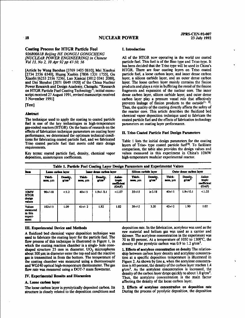
Table 1 lists the initial design parameters for the coating layers of Triso- type coated particle fuel'31. To facilitate comparison, the table also provides the design values and values measured in this experiment in China's 10MW high-temperature modular experimental reactor.
Table 1. Particle Fuel Coating Layer Design Parameters and Experimental Values Item Loose carbon layer Inner dense carbon layer Silicon carbide layer Oater dense carbon layer
Thick- ness, um
Density, f/cnr>
Thick- ness, |im
Density, a/cnr*
Aniso- tropie
coefficient (OAF)
Thick- ness, urn
Density, g/cnr3
Thick- ness, (im
Density, g/cm3
Aniso- tropie
coefficient (OAF)
10MW HTGR design values
90+7-18 <1.2 40+/-5 1.9+/-0.1 <1.07 35+/-5 2:3.18 40+/-5 1.9+/-0.1 <1.05
Values measured in this experi- ment
102+/-5 1.09 41+/- 2 1.92 1.02 38+/-2 3.20 42+/-2 1.90 1.02
m. Experimental Device and Methods A fluidized bed chemical vapor deposition technique was used to fabricate the coating layer for the particle fuel. The flow process of this technique is illustrated in Figure 1, in which the coating reaction chamber is a single- hole cone- shaped structure 25 mm in diameter. U02 microspheres about 500 urn in diameter enter the top end and the reactive gas is transmitted in from the bottom. The temperature of the coating chamber was measured using a thermocouple and WGJ40 optical high-temperature thermometer. The gas flow rate was measured using a DOT-7 mass flowmeter.
IV. Experimental Results and Discussion
A. Loose carbon layer The loose carbon layer is pyrolytically deposited carbon. Its structure is closely related to the deposition conditions and
deposition rate. In the fabrication, acetylene was used as the raw material and helium gas was used as a carrier and thinner. The acetylene concentration in the experiment was 70 to 80 percent. At a temperature of 1050 to 1300°C, the density of the pyrolytic carbon was 0.9 to 1.2 g/cm3.
1. Effects of acetylene concentration on density The relation- ship between carbon layer density and acetylene concentra- tion at a specific deposition temperature is illustrated in Figure 2. As shown by line a, when the acetylene concentra- tion is 60 percent, the density of the carbon layer reaches 1.4 g/cm3. As the acetylene concentration is increased, the density of the carbon layer drops quickly to about 1.0 g/cm3. Thus, the acetylene concentration is the main factor affecting the density of the loose carbon layer.
2. Effects of acetylene concentration on deposition rate During the process of pyrolytic deposition, the deposition

JPRS-CEN-92-007 23 July 1992 NUCLEAR POWER 19
Figure 1. FIuidized-Bed Chemical Vapor Deposition Technique Flow Process Diagram Key: 1. Temperature measurement thermocouple; 2. Exhaust outlet; 3. Optical high-temperature thermometer, 4. Reaction chamber, 5. Constant temperature chamber, 6. Methyl trichlorosilicane; 7. Mass flow meter, 8. Helium gas; 9. Hydrogen gas; 10. Acetylene; 11. Propane (methane)
1.4 r» \ j C V w \ ^% \ *1.2
\
Ö m "'4 = 1.0 / kCt ,/ 1. /
0.8 50 70
C&&&- * 3.
1G0
120 |
E a»
80 &<
cc
40 te
2.
90
Figure 2. Relationship of Carbon Layer Density and Deposition Rate to Acetylene Concentration Key: a. Carbon layer density; b. Deposition rate; 1. Carbon layer density; 2. Deposition rate; 3. Acetylene concentration

20 NUCLEAR POWER JPRS-CEN-92-007
23 July 1992
rate is closely related to the acetylene concentration (see line b in Figure 2). When the acetylene concentration is 73 to 80 percent, the deposition rate can reach 140 um/min. Thus, a high acetylene concentration and high deposition rate are the main factors behind a porous and loose carbon layer.
B. Dense carbon layers Methane, propane, propylene, and so on can be used as the raw material in fabrication of the isotropic dense carbon layers141. The primary technical parameters that affect the structure and performance of the dense carbon layers include deposition temperature, reactive gas concentration, amount of material loaded, reaction time, and so on. This experiment used methane and propylene as the raw mate- rials and helium gas as a carrier and thinner.
1. Fabrication of the dense carbon layers using methane as a raw material a. Effects of deposition temperature on carbon layer density. The relationship between pyrolytic carbon density and deposition temperature is illustrated in Figure 3. Figure 3 shows that dense pyrolytic carbon layers with a density greater than 1.80 g/cm3 can be fabricated at temperatures under 1300*C and temperatures over 1700*C.
b. Effects of deposition temperature on anisotropism. The anisotropism coefficient (BAF) of the dense carbon layers decreases as the temperature is raised (Figure 4). The slope of the curve at low temperatures is relatively large, indi- cating that there is an obvious preferred orientation during pyrolytic carbon deposition. As the temperature is
2.4
E
*-2.0
•je 1.6
a.
1.2 1200 1400 1600 1800
Figure 3. Relationship Between Deposition Rate and Temperature
Key: 1.40 percent CH4; 2.33 percent CH4; a. Deposition rate; b. Deposition temperature
< m
c <L>
•H o
•H M-4 *H
Oi O o
g VI
•H P« o
+■> o en
•H
5
5 0
3. or \
1.0
I:%C1U
1500 '40° * ISM Temperature ,•£
ISOO
Figure 4. Relationship Between Deposited Carbon Anisotropism Coefficient and Temperature

JPRS-CEN-92-007 23 July 1992 NUCLEAR POWER 21
5:1-20 c \^
&1.10 WS
Si.00
a.
2.0|
i ft183
jl.6 1100 1200 1300 1400 1500 c.
Figure 5. Relationship of Deposition Density and Deposited Carbon Anisotropism Coefficient to Temperature Key: a. Anisotropism coefficient; b. Deposition temperature; c. Deposition density; 1. Deposition density; 2. Deposited carbon anisotropism coefficient
increased, there is an extremely rapid reduction in the preferred orientation and the anisotropic coefficient tends toward 1.
Taking comprehensive consideration of these factors, choosing a deposition temperature of about 800°C and a methane concentration of 20 percent can produce dense carbon layers that meet design requirements. This pyrolytic carbon is call high-temperature isotropic dense pyrolytic carbon (HTI-PYC).
2. Fabrication of the dense carbon layers using propylene as a raw material a. Effects of deposition temperature on density. The rela- tionship of carbon layer density to changes in deposition temperature are illustrated by curve 1 line Figure 5. The figure shows that at temperatures between 1200 and 1400°C, the density of the fabricated pyrolytic carbon is greater than 1.80 g/cm3.
b. Dense carbon anisotropism. Curve 2 in Figure S shows the relationship of the anisotropism coefficient (OAF) of the carbon layers to changes in temperature for a propylene concentration of 7 percent. The figure shows that when the temperature is below 1250'C, the anisotropism coefficient of the carbon layers is greater than 1.06. As the temperature rises, the anisotropism coefficient of the carbon layers is reduced and tends toward 1. Thus, using propylene as a raw material to fabricate high density isotropic pyrolytic carbon layers at a deposition temperature of 1300 to 1400°C and with a propylene concentration of about 10 percent can produce dense carbon layers that conform to the require- ments of design indices. This dense carbon is also called low-temperature isotropic pyrolytic carbon (LTI-FYC).
C. Silicon carbide layer
Many raw material gases (and liquids) can be used to fabricate silicon carbide. This experiment used methyl trichlorosiucane (MTS) with hydrogen gas as a reducing agent and helium gas as a carrier and thinner. Besides the deposition temperature, MTS concentration, and deposi- tion rate, other primary factors that affected the perfor- mance and structure of the SiC were the specific volume of hydrogen and helium, and so on,5].
1. Effects of temperature on density Figure 6 is the relation- ship curve between the density of the silicon carbide and the deposition temperature. Figure 6 shows that as the temper- ature is raised, the density of the silicon carbide increases rapidly and that when the temperature is higher than 1400°C, the density reaches about 3.20 g/cm3.
2. Effects of specific volume of hydrogen and helium on density Figure 7 is the relationship curve between the density of the silicon carbide and changes in the hydrogen gas content. Figure 7 shows that at a hydrogen gas content under 40 percent, the density of the silicon carbide is rather low. This indicates that a small amount of hydrogen gas aids in decomposing the methyl, causing a surplus of carbon in the coating, which thereby reduces the deposition density.
3. Effects of temperature on microhardness The relationship between the microhardness of the silicon carbide layer and deposition temperature is illustrated in Figure 8. For a specific amount of hydrogen gas, the hardness is relatively low at lower temperatures. When the temperature is higher than 1500°C, the microhardness of the silicon carbide is greater than 3,800 kg/mm2.

JPRS-CEN-92-007 22 NUCLEAR POWER 23 July 1992
•
bO . 3.4 £ (/) ^1^^^^ Ö >^+ 0) ^r .
n3 • ^^
Ö /▼ ° 3.0 /^
•H g ■P / •H §
to i O / P. i o f o 7
2.6 i ii i i M
11 00 1300 1500 Deposition temperature »*C
Figure 6. Relationship Between SiC Density and Temperature
» 6 V
6*3.5 «k
4-> • •H y^ "> i
w r ß' / fl> f
t> 1
c: *» c i i it ,|
.2 o 40 80 ■p •H H2 content, percent O . P< <D o
Figure 7. Relationship Between SiC Deposition Density and H2 Content *

JPRS-CEN-92-007 23 July 1992 NUCLEAR POWER 23
5000 40?SH2
3 a.
1000 100 1300 If) 00
•■■'•'■• HI -o »A- er 1700
Fignre 8. Relationship Between SiC Deposition Temperature and Hardness Key: a. Microhardness; b. Deposition temperature
In comprehensive consideration of the various factors out- lined above, when using MTS as a raw material to fabricate the silicon carbide layer, a deposition temperature of 1500 to 1600"C should be selected. For MTS of approximately 1.6 percent and a hydrogen gas content of SO percent, as well as rationally selected technical parameters, an SiC layer that satisfies design requirements can be obtained.
The coating technique described above was used to fabricate Triso-type coated particle fuel with a concentration of 10 percent and irradiation experiments were conducted in the HFETR. The irradiation results indicated that the atomic burnup percentage reached l.S percent and that the room temperature puncture and fission gas release rates were less than 10-7.
V. Conclusion 1. An acetylene concentration greater than 70 percent and a deposition temperature of 1030 to 1150°C can produce a porous loose pyrolytic carbon layer with a density of less than 1.15 g/cm .
2. A methane concentration under 25 percent, a deposition temperature > 1700°C, and a deposition rate < 5 um/min can produce isotropic dense pyrolytic carbon layers with a density > 1.80 g/cm3.
3. A propylene concentration of about 10 percent and a deposition temperature of 1200 to 1400°C can produce dense pyrolytic carbon layers with an isotropic density > 1.80 g/cm3.
4. Using methyl trichlorosilicane as a raw material, a deposition temperature of 1500 to 1600"C, an MTS concen- tration of about 1.6 percent, and a hydrogen gas content of 50 percent can produce a B-phase silicon carbide layer with a density > 3.18 g/cm3.
5. Irradiation of Triso-type coated particle fuel fabricated on the basis of the conditions described above showed that when the atomic burnup percentage is 1:5 percent, the fission gas release rate is still less than 10'7.
References
[1] Tranger, D. B., ORNL-4200, 1967.
[2] Allen, P. L. et al., Nuclear Technology, Vol 35, No 2, 1977 p 246.
[3] Xu Shijiang [1776 0013 3068], Gaowen Qileng Dui Ranliao Yuanjian Sheji [Design of Fuel Elements for High- Temperature Gas-Cooled Reactors], not published, 1990.
[4] Gyarmati, E. et al., Jul-1052-RW, 1974.
[5] Federer, J. I., ORNL/TM-5152, 1976.
Preparation of HTGR Fuel Kernels By Internal Gelation Process 926B0081C Beijing HE DONGLIGONGCHENG [NUCLEAR POWER ENGINEERING] in Chinese Vol 13, No 2, 10 Apr 92 pp 51-56
[Article by Cao Xinsheng [2580 2450 3932], Wang Fapin [3769 4099 0756], Wang Luquan [3769 6922 0356], Chen Ze'en [7115 3419 1869], Ji Changhong [1213 7022 7703], Guo Shulian [6753 3219 5571], and Liu Baojin [0491 0202 6855] of the China Nuclear Power Research and Design Academy, Chengdu; initial manuscript received 10 October 1991, revised manuscript received 23 November 1991]
[Text]

24 NUCLEAR POWER JPRS-CEN-92-007
23 July 1992
Abstract
The internal gelation method was used to develop high- temperature gas-cooled reactor (HTGR) fuel kernels. Sys- tematic research was done on every process in this tech- nique including acid-deficient uranyl nitrate solution and sol liquid preparation, dispersing the sol liquid into droplets and gelating it to make solid microspheres, washing, drying, calcining, reducing, and sintering, and other processes, and optimized conditions experiments were conducted in a 1 leg-grade device to determine the optimum technical param- eters. The density of the U02 fuel kernels fabricated using this technique exceeded 98 percent of the theoretical density and had an O/U ratio of 2.O0O+/-O.005, a sphericity (D^J Dnün) of 1.03, a crushing strength of 2 kg, and a closed pore
size of about 1 um. The performance of all items met the requirements for fuel elements for China's 10MW HTGR.
Key terms: high-temperature gas-cooled reactor, fuel ker- nels, uranium dioxide, internal gelation method.
I. Introduction
The use of all-ceramic fuel elements with a graphite matrix and dispersed coated particle fuel in high-temperature gas- cooled reactors significantly improves their fuel element burnup, reactor safety, and range of applications. The fuel kernels in the coated particles are fabricated using a sol-gel technique. Sol-gel techniques are mainly divided into four methods in two categories, as illustrated in Table 1.
Ta We 1. Classification of Sol-Gel Techniques filtgwj Mette« NaaM of techniqae Dehydration gelation Extraction of water in the IOI to geUte the sol External gelation technique High pH gelation Extraction of the acid to raise the sol pH
value and cause the sol to geUte Internal gelation techniques
Bringing in NH3 and NH4+ from the outside to raise the sol pH value and cause the sol to geUte
Decomposing and releasing the HMTA in the sol to raise the pH value and cause the sol to geUte
The ORNL-CUSP process1'1 in the external gelation method is a dehydration-gelation method. Italy's CNEN process121 is a technique that involves the extraction of acid to increase the pH value and cause gelation of the sol. Both of these techniques require extraction and catalytic reduction pro- cesses and the operations after reduction must be carried out in a protected atmosphere, so the overall process is complicated and slow. Other processes like Italy's SNAM131
require the addition of organic polymer thickeners (such as methyl cellulose) to provide a network so that the sol can maintain a particular shape during gelation. Moreover, tetrahydrofurfuryl alcohol must be added to improve the shape of the gel spheres. The irradiation stability of the thickener that must be added in this method is rather low, so a substantial number of organic additives must be added to help maintain the required viscosity, and the sphericity of the spheres that are ultimately produced is less than ideal. Germany's gelation precipitation process141 is a more ideal external gelation technique but the washing and drying steps
involved are rather complicated. The external gelation method often contains large amounts of organic additives due to the relative softness of the gelated spheres and requires the use of special measures during the washing and drying procedures like azeotropic (or reduced pressure) distillation, single-layer drying, and so on, which makes subsequent operations after gelation relatively difficult.
Representative processes for the internal gelation technique include Holland's KEMA process151 and Germany's KFA-H process161. The China Nuclear Power Research and Design Academy in Chengdu also used the internal gelation tech- nique to develop ceramic nuclear fuel microspheres171.
This article introduces research work on using the internal gelation technique to fabricate HTGR fuel kernels.
II. Internal Gelation Technique Process Figure 1 illustrates the internal gelation technique process used in this article.
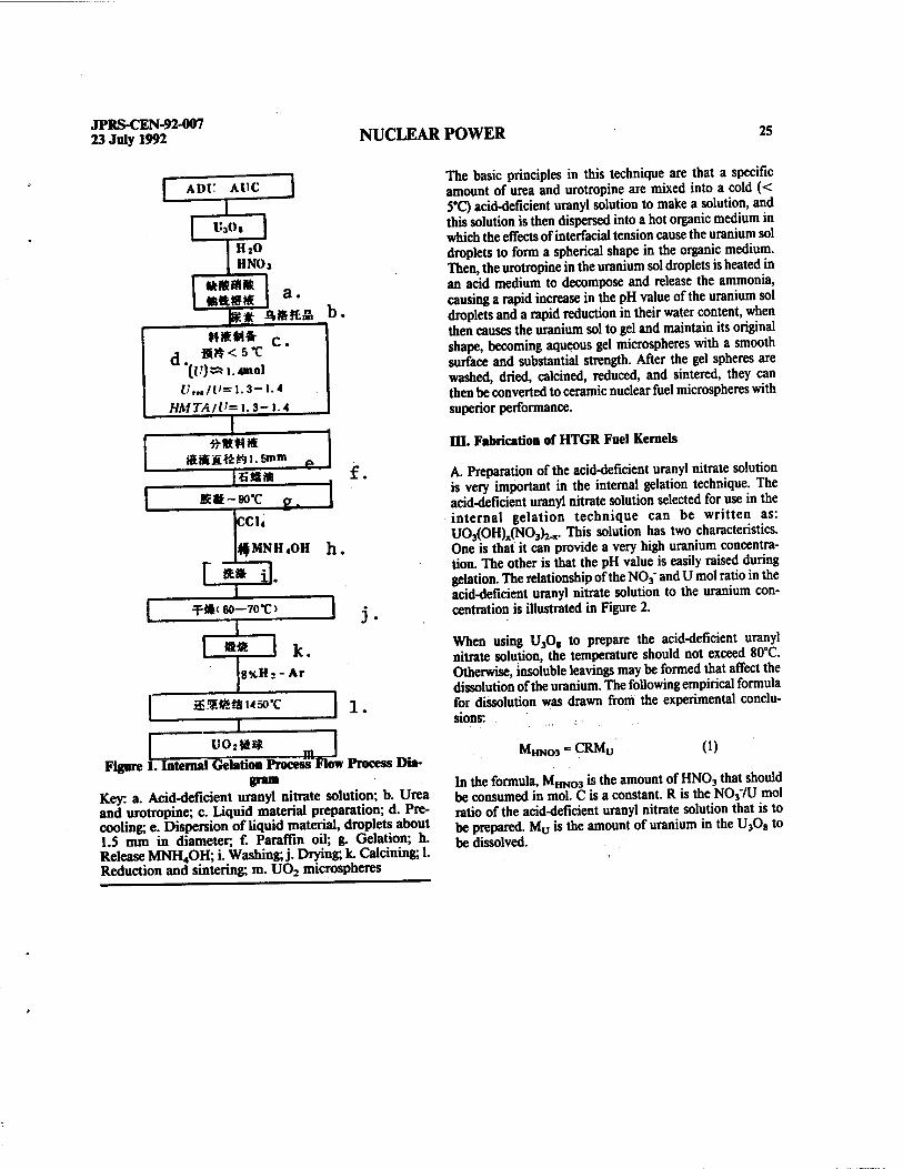
JPRS-CEN-92-007 23 July 1992 NUCLEAR POWER 25
ADi: AUC ED i'3o,
HNOj
L a.
d. »»«ft c **<5*C
((f)» 1. «mol l/„./l'=1.3-1.4
HMTA/V=\.3-\.4 f^ iBJS»
R*-90*C 13 ecu *MNH4OH h.
r*» il. T<t'60—70*C>
I «Ä k.
8%Hj-Ar
aSiSiSuso'C
Figure E I
l.
-n, U(>2»** Internal Gelation Process Flow Process Dia-
gram Key: a. Acid-deficient uranyl nitrate solution; b. Urea and urotropine; c. Liquid material preparation; d. Pre- cooling; e. Dispersion of liquid material, droplets about 1.5 mm in diameter, f. Paraffin oil; g. Gelation; h. Release MNH4OH; i. Washing; j. Drying; k. Calcining; 1. Reduction and sintering; m. UÖ2 micro-spheres
The basic principles in this technique are that a specific amount of urea and urotropine are mixed into a cold (< 5'C) acid-deficient uranyl solution to make a solution, and this solution is then dispersed into a hot organic medium in which the effects of interfacial tension cause the uranium sol droplets to form a spherical shape in the organic medium. Then, the urotropine in the uranium sol droplets is heated in an acid medium to decompose and release the ammonia, causing a rapid increase in the pH value of the uranium sol droplets and a rapid reduction in their water content, when then causes the uranium sol to gel and maintain its original shape, becoming aqueous gel microspheres with a smooth surface and substantial strength. After the gel spheres are washed, dried, calcined, reduced, and sintered, they can then be converted to ceramic nuclear fuel microspheres with superior performance.
III. Fabrication of HTGR Fuel Kernels
A. Preparation of the acid-deficient uranyl nitrate solution is very important in the internal gelation technique. The acid-deficient uranyl nitrate solution selected for use in the internal gelation technique can be written as: U03(OH)x(NOj)2.v This solution has two characteristics. One is that it can provide a very high uranium concentra- tion. The other is that the pH value is easily raised during gelation. The relationship of the N03
_ and U mol ratio in the acid-deficient uranyl nitrate solution to the uranium con- centration is illustrated in Figure 2.
When using U3Og to prepare the acid-deficient uranyl nitrate solution, the temperature should not exceed 80°C. Otherwise, insoluble leavings may be formed that affect the dissolution of the uranium. The following empirical formula for dissolution was drawn from the experimental conclu- sions:
M, HN03 CRMu (1)
In the formula, MHNCO »the amount of HN03 that should be consumed in mol. C is a constant. R is the N037U mol ratio of the acid-deficient uranyl nitrate solution that is to be prepared. Mu is the amount of uranium in the U3Og to be dissolved.

26 NUCLEAR POWER JPRS-CEN-92-007
23 July 1992
820
T40
b£
660
t>80 •3 .. 1.5 1.7 1.9
NOI/U mo! ratio Figure 2. Effects of N037U Mol Ratio on (U) (20 °C)
2.1
We have successfully prepared acid-deficient uranyl nitrate solution with N037U - 1.6 and a concentration of 3 mol/L according to formula (1), with very good repeatability. The relationship between the uranium concentration in the acid-deficient uranyl nitrate solution we prepared and the specific gravity of the solution is illustrated in Figure 3. The figure shows that the uranium concentration has a positive relationship to the specific gravity of the solution and forms a linear relationship.
B. Sol liquid preparation and gelation
The mol ratio of the urea and urotropine to the uranium used for preparation of the sol liquid is 1.3 to 1.4. This type of sol liquid has a sufficiently long shelf life, so it has enough time to be dispersed into droplets in the technique and will not solidify too soon.
The main function of the urea is to complex the uranyl ions to prevent the uranium from precipitating. The urea can

JPRS-CEN-92-007 23 July 1992 NUCLEAR POWER 27
1.35
75-
c to
>s <4-> •H > u M
u •H «4-1
u a, w 1.65
490 590 Concentration , g/L •
Figure 3. Relationship Between Concentration of Ura- nium inArid-Deficient Uranyl Nitrate Solution and Spe-
cific Gravity of Solution
also react with the formaldehyde that is released when the urotropine is heated and decomposed to form a condensed product, carbamide resin, which accelerates decomposition of the urotropine and spurs gelation.
o NH-C-NH,
»CH, AH-C-NH-CH-NH-C-NH,
o o
HCHO+CO(NH0r (2)
The urotropine is hydrolyzed when it is heated in the acidic medium and the ammonia that is released causes an abrupt rise in the pH value of the uranium sol, which leads to gelation. The hydrolysis reaction of the urotropine is:
(CH2).N4+10H2O^6HCHO+4NH,OH (3)
Because the urotropine is evenly dissolved in the uranium solution, the gel spheres that are produced have a homoge- neous internal structure and cannot form shell layers and stress. Because the speed of decomposition of the urotropine increases as the temperature rises, the gelation temperature
can be controlled to regulate crystal formation within the gel spheres and the rate of crystal growth, which thereby pro- duces excellent gel spheres.
Research has shown that adding too much urotropine can made it hard for the liquid material to disperse, forming amorphous precipitates and causing cracking of the micro- spheres. Adding too little makes the gel spheres too soft and hard to deal with in subsequent procedures.
Gelation was carried out in hot paraffin oil to which Span80 had been added. The Span80 was added to prevent the gel spheres from sticking together and forming cylindrical chains. Figure 4 is an illustration of the gelation device.
The dispersion system uses a pressure dispersion with added vibration method. Based on the principle of an average shrinkage rate of about 3 in radius in the process from gel spheres to the final the U02 microsphere product, we used dispersers with different apertures, dispersion pressures, and vibration frequencies to fabricate gel spheres 3 times the diameter of the finished U02 microspheres. This can also be calculated using the following formula:
——». /I vl/3 690 '-«.(-£-) (4)
In the formula, d, is the diameter of the sol droplets, dy is the diameter of the final U02 microspheres, C, is the concentration of uranium in the sol, and K is a constant.
C. Washing the gel spheres Washing of the gel spheres is carried out in three steps, using carbon tetrachloride, then using diluted ammonia water, and then using deionized water. The carbon tetrachloride is used to wash away the paraffin oil that has adhered to the gel spheres. The diluted ammonia water is used mainly to wash away the NH4N03 and other water soluble materials to improve the heat treatment performance of the gel spheres. This is because NH4N03 is commonly felt to be one of the main reasons for cracking of the microspheres during the heat treatment process.
D. Gel sphere drying and calcining The drying is carried out in 60 to 70°C air in a drying oven for a drying time of 20 hours. When the drying begins, the temperature should be increased at a slow rate. A too-large heat gradient can cause cracking of the gel spheres, incom- plete washing of the gel spheres, and improper mixing of the sol liquid. A too-high gelation temperature, etc., are the reasons for cracking. After drying, the gel spheres can be calcined in the drying oven. They can also be slowly cooled and then transferred to a muffle furnace for calcining. The temperature should be raised at a slow rate during calcining.

28 NUCLEAR POWER JPRS-CEN-92-007
23 July 1992
j &'-?X a.
££,&£ b.
____ Figure 4. Illustration of Gelation Device Key: 1. Material reserve tank; 2. Material intake; 3. Material intake tube; 4. Disperser, 5. Gelation cylinder; 6. Heating element; 7. Valve; 8. Gel sphere storage tank; a. Cold water, b. Vacuum, pressure chamber
The experimental results for different temperatures and conditions are listed in Table 2.
Table 2. Effects of Different Calcining Conditions on Gel Sphere Performance oc^pcscc Calcining li mn nlm i Obsmatioa by stereoscopic microscope Density after calcining, per-
After calcining After sintering cent TJ).
1 Drying box 220*C Light yellow, yellowish brown color
Silvery white, lustrous spheres
100
2 Drying box 220*C, transfer to muffle furnace at 3S0*C
Yellow, brown color Silvery white, lustrous spheres
99.2
3 Muffle furnace, 350*C Brown, coffee, green color Silvery white, lustrous spheres
98.3
4 Muffle furnace, 220*C Yellow, darker surface Silvery white, lustrous spheres
97.7

JPRS-CEN-92-007 23 July 1992 NUCLEAR POWER 29
Table 2 shows that different calcining temperatures only affect the color of the gel spheres, with deeper colors at higher temperature. However, no effects were noted on the density of the U02 microspheres within the temperature range of this experiment.
E. Gel sphere reduction and sintering Reduction and sintering of the calcined gel spheres was carried out in a medium-frequency sintering furnace. The atmosphere was 8 percent H2.Ar. The temperature should
be raised at a slow rate and held for 3 hours after reaching 1450°C, then reduced at the rate of 600°C/hour down to 600°C and then cooled naturally down to room temperature for removal of the microspheres. The density of the U02 spheres obtained is greater than 98 percent T.D. and the O/U ratio is 2.O0O+/-0.0O5.
F. Performance of the finished U02 microspheres Table 3 shows the performance of the finished U02 micro- spheres. Their performance satisfies the design require- ments for China's 10MW HTGR fuel elements.
Table 3. Performance Indices for U02 Microspheres O/U Density, T.D.
percentage Crushing
strength, kg/ sphere
Dimensions, urn
Sphericity, Dmax/Dmin
Contaminant content
Granularity, um
Closed pore dimensions,
urn
2.O00+/-0.005 >98 2 50O+/-25 1.026*- 1.09 Conforms to specifications
12-15 1
This data taken from reference [8].
IV. Conclusion References
We successfully used the internal gelation technique to fabricate fuel kernels that conform to the design require- ments for the fuel elements for China's 10MW high- temperature gas-cooled experimental reactor and provided a substantial number and variety of U02 microspheres for the coating technique. We did technical experiments and irradiated samples, and have now selected various technical parameters: 1) Preparation of acid-deficient uranyl nitrate solution; 2) Sol liquid preparation and gelation conditions; 3) Washing, drying, calcining, reduction, and sintering pro- cedures. Using the technical parameters we selected to fabricate U02 microspheres has relatively good repeat- ability.
He Changqing [0149 7022 3237], Wang Jianhong [3769 02S6 4767], and other comrades participated in some of the research work.
[1] Wymer, R. G., IAEA Panel on Sol-Gel Processes, Vienna, 6-10 May, 1968, pp 43. [2] Zifferero, M., IAEA Panel on Sol-Gel Processes, Vienna, 6-10 May, 1968, p 9. [3] BrambiUa, G., et al., Energia Nuclear, Vol 17, No 4,1970 p217. [4] Wewerner, Heit, et al., Nuclear Technology, No 69,1985 pp 44-54. [5] Hermans, M. E. A., et al, IAEA Panel on Sol-Gel Processes, Vienna, 6-10 May, 1968, p 21. [6] Kanij, J. B. W., et al., IAEA-161, 1975 p 185. [7] Gu Shuchuan [7357 2885 1557], et al., He Dongli Gongcheng [Nuclear Power Engineering], Vol 1, No 2,1980 p 59. [8] Cao Xinsheng [2580 2450 3932], et al., JAERI- M-89-180, 1989.

30 CONSERVATION JPRS-CEN-92-007
23 July 1992
Wang Yiping on Conservation, Comprehensive Use of Energy Resources 926B0096A Beijing ZHONGGUO NENGYUAN [ENERGY OF CHINA] in Chinese No 5, 25 May 92 pp 1-3
[Excerpts from speech on 16 March 1992 by Wang Yiping [3769 0001 1627], secretary-general of the State Council Production Office: "Speech By Comrade Wang Yiping at the Conservation and Comprehensive Utilization Work Conference of Some Regions and Departments (Excerpts)"]
[Text] I want to discuss some views regarding my experi- ences during the less than one-half year since the Production Office established the Conservation and Comprehensive Utilization Bureau in 1991 until now.
1. Conservation and comprehensive utilization have been better integrated with technical upgrading work in enter- prises. Technical upgrading must be focused on energy conservation and reduced consumption, and energy conser- vation (including conservation of materials and comprehen- sive utilization) must be carried out under overall plans and guidance for technical upgrading, and they should be inte- grated well. In a situation of a rapidly growing national economy and continual improvements in people's living standards, substantial resource shortages, of energy resources in particular, have now become one of the main factors that are restricting development of our national economy at the present time. After the 3d Plenum of the 11th CPC Central Committee, the CPC Central Committee proposed the energy resource principle of "combining development and conservation". For more than a decade, China's energy conservation work has made substantial achievements under guidance by this principle. The average annual rate of growth in our GNP over the past 10 years was 9 percent, but consumption of energy resources grew at an average yearly rate of only S percent. Average energy con- sumption per 100 million yuan in GNP dropped from 13.36 tons of standard coal in 1980 to 9.26 tons of standard coal in 1990, for total energy savings of 280 million tons of standard coal. Energy consumption levels also dropped to varying degrees for several important products and there have been substantial improvements in die degree of energy resource utilization that played an important role in pro- moting and ensuring sustained growth of China's national economy during the 1980's.
However, looking at future development trends, to qua- druple China's GNP by the end of this century compared to 1980, the first decade has already passed and it must grow at an average yearly rate of 6 percent over the next lO.years. Based on present possibilities, energy resource production is only expected to grow by 3 percent and reach 1.4 billion tons of standard coal, which means that energy resource produc- tion must double to ensure a quadrupling of our national economy. To solve the problem of our energy resource shortage, we must both develop and conserve. Looking at actual circumstances, there is truly great potential for energy conservation in China. Before 1983, China's GNP lagged several-fold behind Japan but total energy consumption by China's industry exceeded that in Japan. Average energy resource utilization rates in China at present are only
equivalent to two-thirds of advanced levels in foreign coun- tries and unit consumption for several primary industrial products is 40 percent higher than advanced levels in foreign countries. There are many reasons for this situation, including the problem of our industrial structure, the problem of backward technical equipment levels, the problem of irrational overall industrial flow processes, and so on, but there is still potential that can be exploited regardless of the causes.
Premier Li Peng pointed out in his report concerning the 10-Year Plan and Eighth 5-Year Plan outline for develop- ment of our national economy and society that the focus of technical upgrading in the future should be on energy conservation, reducing consumption of raw materials, reducing production costs, and preventing pollution along with reinforced comprehensive utilization of resources. The relationship between energy conservation and technical upgrading is that the focus of technical upgrading should be placed on energy conservation. This provides a clear direc- tion for our energy conservation work. At the National Enterprise Technical Upgrading Conference, vice premier Zhu Rongji [2612 6954 1015] called for developing "five highs and two lows products". The "five highs and two lows" refer to high technical content, high market capacity, high added value, high foreign exchange earnings, and high benefits, low energy consumption, and low materials con- sumption. This means greater prominence for energy con- servation and reduced consumption in technical progress, readjustment of the product mix, and improvement of enterprise economic results. China now faces a multitude of tasks in using technical upgrading to conserve energy. Our energy conservation work and technical upgrading must be better integrated and use technical upgrading to achieve energy conservation tasks. In the final analysis, energy conservation work requires faster technical progress. If we do not accelerate technical progress, our lag behind foreign countries will continue to grow, because foreign countries are also developing! Thus, I feel that we must have a deeper understanding of focusing on energy conservation in car- rying out technical upgrading, fully acknowledge that tech- nical upgrading for energy conservation is an important area or important route in our energy conservation work, and in particular focus at present on the favorable opportunity of reform and opening up to accelerate the pace of our energy conservation and reducing consumption.
Energy conservation is not just a task for comrades involved in energy conservation departments or for the State Council Production Office's Conservation Bureau. The tasks for energy conservation departments or engineers involved in energy conservation in all regions should be embodied in work in all areas and all departments, meaning that energy conservation is a strategic policy for development of our national economy as a whole, and must be adhered to in work in all areas in every sector of our national economy. First, design personnel should have an ideology of energy conservation, their selection of technical flow processes should conform to the principle of energy conservation, the equipment they choose should be energy-saving equipment, energy conservation projects after going into operation should be managed according to energy conservation

JPRS-CEN-92-007 23 July 1992 CONSERVATION 31
methods, waste of energy resources should be prevented, and so on. Another example is upgrading in old plants, which must take into consideration the need to conserve energy and reduce consumption. In this sense, our comrades who are involved in energy conservation work are merely organizing or promoting energy construction work. If they truly want to achieve their energy conservation tasks, they must be embodied in all areas in the work of all departments from ideology to practice and implementation. The same holds true for materials conservation and comprehensive utilization.
2. Reinforce energy conservation management work. At identical equipment levels, differences in management levels can result in substantial differences in energy resource consumption, and it is entirely possible for an additional 10 to 20 percent to be consumed. This means that for identical equipment levels, the quality of management work has a direct impact on the amount of consumption. Thus, rein- forcement of enterprise energy conservation management should be said to be an organic part of enterprise manage- ment as a whole. Energy consumption levels are a compre- hensive reflection of management levels in the enterprise. Improving energy conservation management levels in the enterprise itself is the key to our reinforcement of energy conservation management. A very important point here is that enterprises should be able to manage themselves. What, then, should professional administrative cadres in adminis- trative departments be involved in? Three things, I think— leading, guiding, and providing information. We can announce international, domestic, and industry-wide advanced energy consumption levels at fixed times so that everyone knows what's what and knows that there is still a heaven outside of heaven, makes comparisons to seek out differentials, and causes enterprises to self-consciously rein- force energy conservation management. The foundation for reinforcing energy conservation management is quota man- agement. Unit consumption for products is the hardest indicator reflecting energy consumption levels. If unit con- sumption for several products can attain advanced interna- tional or domestic levels each year and several of these products can enter advanced ranks each year, our energy conservation work could move up to a new stage. We should know each year how many product varieties have advanced energy consumption levels and how many of them have attained normal international levels, how many are advanced in China as a whole, how many are normal, and how many are very poor. There is work to be done in this area in every region and every department, as well as in the Conservation Bureau of the State Council Production Office. We hope that everyone will make advances in the lags and use comparisons to fight for advances. Many enterprises have created many good experiences in this area. An example is the No 1 Automobile Manufacturing Plant. Their experience is to begin with quota management and focus on this key aspect, make reducing unit consumption for products their objective and focus on a foundation and focus on an objective, while at the same time integrating with improvement of overall management and administra- tion to improve economic results in the enterprise. This point is very important. There are still quite a few losses in
enterprises at present. Losing enterprises should make reducing energy consumption and reducing raw materials consumption the main area for turning losses into profits. The reason is that energy consumption and raw materials consumption in industrial enterprises account for the big- gest part of product costs, so reducing energy consumption and reducing raw materials consumption can reduce costs. This is realistic. Thus, reducing energy consumption and reducing raw materials consumption is very important work in our conservation work.
Past work to compare and assess enterprises for raising grades as part of energy conservation work has been tempo- rarily halted and I think assessment of grades was not our objective. Our goal was reducing energy consumption and reducing materials consumption. Now, although compar- ison and assessment work has stopped temporarily, there is still work to be done ahead.
3. The question of focusing on key problems in work. Based on the situation in the Conservation Bureau, I propose that they should focus on key points in their work. What does focusing on key points mean? It means focusing on one or two important aspects of work at a particular stage, key matters, things that can produce real results, and focusing on them to make achievements. The selection of focal points is very important and correct choices are essential.
The focus of work in the Conservation Bureau during 1992 is focusing on trial points for renewal and upgrading of coal mine blowers and water pumps to produce benefits and repay loans. Starting in December 1991, vice premier Zhu Rongji turned tasks over to us calling for comrade Li Junsheng [2621 0971 0581] to focus on upgrading blowers and water pumps to promote overall energy conservation work. One very important point in focusing on this matter is the great potential for energy conservation in coal mine blowers and water pumps. According to statistics from the State Statistics Bureau for 1989, China had over 37 million pumps and blowers of various types with a total installed capacity of 110.000MW that consume one-third of China's total power consumption. Advanced international levels are that the overall inherent operating efficiency of blowers and pumps is generally above 85 percent and the system oper- ating efficiency is about 80 percent. In China at present, however, the inherent design efficiency of Chinese-made equipment is 75 percent but the actual operating efficiency is less than 50 percent and the system operating efficiency is less than 30 percent. Based on this, we are wasting about 20 billion kWh of electricity a year. This shows that the equipment levels of China's pumps and blowers are not high and that their excess electricity consumption each year is startling. This is a nationwide situation. Looking at industry conditions, old equipment from the 1950's and 1960's accounts for one-third of the blowers and pumps in the coal industry and some are still in use from the period of the Japanese puppet regime in China. The Ministry of Energy Resources has estimated that the inherent operating effi- ciency of our coal mine blowers and pumps is only 30 to 40 percent and the system operating efficiency is about 20 percent, which wastes large amounts of electricity and has negative effects on safe production in coal mines. Starting

32 CONSERVATION JPRS-CEN-92-007
23 July 1992
with this reality, leaders in the State Council have decided that the Conservation Bureau in the State Council Produc- tion Office should concentrate forces to focus on this matter. With the approval of leaders, 50 million yuan was set aside for demonstrations and exploration. Leading com- rades in the State Council are very concerned with this matter and comrade Zhu Rongji issued the instruction: "This is a major matter in energy conservation". This matter has received considerable support from the relevant departments and localities. Work in this area is now pro- ceeding smoothly. While I am talking about this matter, I would like to explain that it is the focus of the present stage of our energy conservation work. We are preparing to do independent accounting of energy conservation benefits, meaning that the difference in electricity use before and
after upgrading will be measured to calculate electricity savings and use overall electricity prices for enterprises as a basis for computing benefits to calculate the benefits from each item of electricity conservation. With support from the Ministry of Finance, we very quickly formulated a provision for trial implementation of a project to use the electricity conservation benefits from blower and pump upgrading in the coal industry for loan repayment. This experiment was successful, and it shows that we have taken a new route and opened up a new situation in our energy conservation work, and we hope that everyone will provide more support. At the same time, even more important is that we hope that everyone will choose one or two matters to focus upon based on the situation in their own departments and regions and we will certainly provide everyone with support within the scope of our abilities.
Table 1. Energy Resource Output By Product Variety, January-February, 1992
1KB Units Jaaaary-Febraary Percentage increase in total for January-February compared to same period
In 1992
Total Daring month
Total energy resource output
Million tons of standard coal
143.97 64.42 -1.9
Raw coal Million tons 141.51 60.89 -3.9
Unified distribution coal mines
Million tons 74.88 34.19 -5.3
Local medium-sized and small coal mines
Million tons 66.63 26.70 -3.6
Washed and dean coal coked
Million tons 10.18 4.93 -3.2
Coke (machine coke) Million tons 9.1504 4.4994 7.3
Crude oil Million tons 23.348 11.351 3.4
Amount of crude oil pro- cessed
Million tons 20.444 10.177 13.0
Gasoline Million tons 4.608 2.329 26.4
Kerosene Million tons 0.628 0.324 2.6
Diesel Million tons 5.109 2.649 20.4
Lubricating oil Million tons 0.355 0.182 4.3
Heavy oil Million tons 5.549 2.88 8.6
Natural gas Billion cubic meters 2.558 1.283 0
Electricity output Billion kWh 112.99 55.15 10.2
Hydropower Billion kWh 15.18 7.45 3.2
Thermal power Billion kWh 97.7 47.56 11.2

JPRS-CEN-92-007 23 July 1992 CONSERVATION 33
Table 2. Energy Resource Output By Product Variety, January-March, 1992 Item Units Janaary-Febraary Percentage increase in
total for Janaary-March compared to same period
in 1992
Total Daring month Total energy resource output
Million tons of standard coal
228.76 86.47 -0.7
Raw coal Million tons 228.16 89.22 -2.3 Unified distribution coal mines
Million tons 119.16 44.28 -2.7
Local medium-sized and small coal mines
Million tons 109.00 44.94 -1.7
Washed and clean coal coked
Million tons 16.17 5.99 -1.8
Coke (machine coke) Million tons 13.8069 4.647 6.4 Crude oil Million tons 35.325 12.003 2.7 Amount of crude oil pro- cessed
Million tons 30.708 10.301 9.9
Gasoline Million tons 6.845 2.192 21.9 Kerosene Million tons 0.995 0.345 3.4 Diesel Million tons 7.841 2.73 18.6 Lubricating oil Million tons 0.554 0.184 6.7 Heavy oil Million tons 8.432 2.795 6.1 Natural gas Billion cubic meters 3.87 1.3 0.3 Electricity output Billion kWh 174.5 61.11 10.8 Hydropower Billion kWh 25.17 9.55 9.1 Thermal power Billion kWh 149.03 51.42 10.9 Provided by State Statistics Bureau
Improving Enterprise Economic Benefits Through Energy Conservation 926B0096B Beijing ZHONGGUO NENGYUAN [ENERGY OF CHINA] in Chinese No 5, 25 May 92 pp 4-6
[Excerpts from speech on 14 March 1992 by Li Junsheng [2621 0971 0581], deputy director of the State Council Production Office Conservation and Comprehensive Utili- zation Bureau at the Conservation and Comprehensive Utilization Work Conference of Some Regions and Depart- ments: "Use Improvement of Economic Benefits in Enter- prises As a Focus for Raising Conservation and Compre- hensive Utilization Work to a New Level"]
[Text] This conference is the first conservation and compre- hensive utilization work conference convened by the Con- servation and Comprehensive Utilization Bureau since the State Council Production Office was established. The cen- tral topics for discussion at this meeting are: summarizing and exchanging situations in conservation and comprehen- sive utilization work during 1991, studying how to focus on running state-run large and medium-sized enterprises prop- erly, improving enterprise economic benefits, and raising conservation and comprehensive utilization work to a new level. To facilitate discussion by my comrades, I will first discuss some points of view.
I. The Situation in Conservation and Comprehensive Utilization Work in 1991
1991 was the first year of the Eighth 5-Year Plan and 10-Year Plan as well as the first year for undertaking "Quality, Product Variety, and Results Year" activities. All regions and all departments have further adhered to the principle of improvement, rectification, and intensive reform, conscientiously implemented all policy measures for doing good work in state-run large and medium-sized enterprises, focused on energy conservation and reduced consumption as important work for turning losses into profits and improving economic results in enterprises, made significant achievements in energy resource and raw mate- rials conservation, and achieved new advances in compre- hensive utilization.
1. Significant results in macro energy conservation. Energy consumption per 10,000 yuan of GNP in China (calculated at constant 1990 prices) dropped from 5.27 tons of standard coal in 1990 to 5.11 tons of standard coal in 1991, for energy resource savings of 32 million tons of standard coal, an energy conservation rate of 3 percent. Energy consumption per 10,000 yuan in gross value of output in industrial departments dropped from 3.04 tons of standard coal in 1990 to 2.88 tons of standard coal in 1991, an energy conservation rate of 5.3 percent. Industrial departments

34 CONSERVATION JPRS-CEN-92-007
23 July 1992
conserved 15.8 billion kWh of electricity, for an electricity conservation rate of 3.3 percent. The achievements made in macro energy conservation were mainly due to continued intensification of reform, significant achievements in improvement and rectification, and the relatively rapid pickup in our national economy.
2. There were reductions in energy resource consumption levels for primary products (work amounts).
3. New advances were made in raw materials conservation and comprehensive utilization.
In 1991, all regions and all departments conscientiously adhered to the spirit of the State Council's 6th Energy Conservation Office meeting and the various tasks set forth in the Huairou [county in Beijing Municipality] Meeting of the State Planning Commission Resource Department in December 1990 in continually intensifying conservation and comprehensive utilization work and creating and accu- mulating many successful experiences and good methods.
1. Management of energy conservation has been further strengthened. Management is the foundation of enterprise energy conservation work. Intensified energy conservation work continually perfects management work. First, focus on management by objectives, assign responsibility, track and evaluate. Governments at all levels have universally included energy conservation indices in their key indicator assessments, implemented various forms of energy conser- vation contractual responsibility systems, divided up and assigned conservation goals by levels to enterprises and individuals, and conducted evaluations at every level. Second, quota assessments are integrated with the interests of enterprises and individual employees. Third, guidance by categories is implemented to focus on weak links. Many regions and departments have divided energy consumption levels into categories, focused on big energy consumers, and focused on energy consumption to restore enterprises.
2. Raise capital through many channels, increase invest- ments in energy conservation. The direction for readjust- ment of industrial policy during the 1990's is to reinforce basic industry, so energy conservation and reduced con- sumption depend mainly on technical progress. The key to technical progress is the capital question, and all regions are using multiple channels to raise capital for energy conser- vation. Over 10 provinces and municipalities in China have now established energy conservation funds.
3. Focus on technical upgrading, implement demonstration projects, extend advanced technology, promote conserva- tion and comprehensive utilization technical progress work.
4. Establishment of laws and regulations for conservation and comprehensive utilization has been further reinforced. In 1991 we organized work to revise the "Energy Conserva- tion Law" in conjunction with the State Planning Commis- sion's Resource Conservation and Comprehensive Utiliza- tion Department and broadly solicited views. Many regions and departments used their own characteristics as a foun- dation for formulating concrete regulations and methods adapted to the conditions in their own regions and depart- ments. Energy resource management is now gradually
shifting from reliance primarily on administrative manage- ment to reliance on management by laws, regulations, and standards.
5. Technical services for energy conservation have played an active role in doing good energy conservation work in state-run large and medium-sized enterprises. First, they helped energy conservation administration departments provide good technical services to energy conservation and provided good advice and assistance. Second, they actively undertook energy conservation monitoring work. Third, they fostered technical advantages and served energy con- servation and reduced consumption in enterprises. Fourth, they carried out energy conservation training and propa- ganda and assisted energy conservation management departments and enterprises in doing good capital construc- tion for energy conservation staffs. In summary, all centers have made positive efforts in the two areas of resolutely serving energy conservation management departments and enterprises and made gratifying achievements.
6. They have widely undertaken energy conservation propa- ganda activities and raised consciousness of all people regarding energy conservation.
Although major achievements were made in 1991 in con- servation and comprehensive utilization work, many prob- lems still exist. One is an inadequate understanding of the importance of conservation and comprehensive utilization work. A second is that direct energy conservation accounts for a too-small proportion of total energy conservation. A third is insufficient capital. The result has been an inability to extend several advanced new energy conservation tech- nologies, techniques, and products; an inability to discard energy consuming equipment that has been ordered aban- doned; an inability to implement several urgent conserva- tion and comprehensive utilization technical upgrading projects, and so on. Fourth, there is not enough balance in the development of energy conservation work among regions and departments.
II. Primary Tasks for Conservation and Comprehensive Utilization Work During 1992
The guiding ideology for conservation and comprehensive utilization work during 1992 is: conscientiously adhere to the spirit of the CPC Central Committee Work Conference and Enterprise Technical Upgrading Conference, intensify reform, focus on conservation and comprehensive utiliza- tion work as an important measure for turning losses into profits, running state-run large and medium-sized enter- prises well, and improving enterprise economic results, focus on key points and manage according to facts, raise conservation and comprehensive utilization work up to a new level.
A. Improve understandings, reinforce leadership Leaders in all regions, all departments and all enterprises must focus on construction and comprehensive utilization work as an important measure to run state-run large and medium-sized enterprises well and improve enterprise economic results, strengthen "energy conservation consciousness", "resource

JPRS-CEN-92-007 23 July 1992 CONSERVATION 35
consciousness", and "environmental consciousness", and truly strengthen leadership over conservation and compre- hensive utilization work.
B. Focus on management, create levels, move np stages The key to reinforcing energy conservation management in enterprises is changing concepts. Management of conserva- tion and reduced conservation in enterprises should gradu- ally achieve a transition from direct management to indirect management and a transition from administrative manage- ment to guidance services, explore new management mech- anisms, and rely more on policies, laws, and regulations to induce and guide enterprises to self-consciously reinforce energy conservation management.
The key in energy conservation management is to focus on consumption quota management.
C. Focus on trial points to use the benefits from coal mine blowers and water pumps to repay loans The state has set aside SO million yuan from technical upgrading capital during 1992 for special loans to be used for trial points to use the benefits from renewal and upgrading of coal mine blowers and water pumps to repay loans. This work has major significance. Its significance lies not only in the importance of upgrading blowers and pumps in coal mines themselves, but lies even more in exploring the route of using benefits to repay loans and developing technical upgrading for energy conservation, so it is an intensification of energy conservation work. If the trial points are suc- cessful, this method can be adopted for other technical upgrading projects in the future, so technical upgrading for energy conservation can move forward even faster. We also hope that all regions and all departments will use survey research to work on one or two similar matters.
D. Solidly implement technical upgrading for conservation and comprehensive utilization The National Technical Progress Conference decided that technical upgrading must focus on conserving energy and reducing consumption. All regions and all departments must give primacy to energy conservation and reduced consumption when they are arranging technical upgrading projects. The focus in 1992 should be on implementation of special energy conservation technical upgrading demonstration projects for 1992, and they should supervise, urge, and inspect the proper alloca- tion of capital and implementation conditions for 1992 energy conservation (materials conservation, comprehen- sive utilization) and rural energy resource technical upgrading projects. They should improve management methods for special energy conservation demonstration projects, formulate "Conservation and Comprehensive Uti- lization Technical Upgrading Special Demonstration Project Scopes, Project Selection Principles, and Primary Technical Directions" and "Project Establishment Proce- dures and Trial Management Methods for Conservation and Comprehensive Utilization Special Technical Upgrading Demonstration Projects". All regions and departments must conscientiously focus on replacing high energy-consuming and discarded electromechanical prod- ucts announced by the state. The key to this item of work lies in implementation. They should formulate plans and measures, supervise, urge, inspect, and implement, and
accelerate the pace of renewal for discarded equipment. They should also actively extend new energy-saving prod- ucts, techniques, technologies, and equipment.
E. Increase investments, reinforce reserve strengths Increased investments cannot depend solely on the state. The dominant factors in investment should develop toward diversification and raise capital through multiple channels. We can also open up channels for cooperation with foreign countries, try to utilize low-interest loans or grants from foreign countries, use them for conservation and compre- hensive utilization, or make joint investments to develop comprehensive utilization and promote the continual inten- sification of conservation and comprehensive utilization work.
F. Intensively develop comprehensive utilization work, pro- mote enterprise "three wastes" [waste water, waste gas, and industrial residues] treatment and environmental protection work Developing comprehensive utilization is a major tech- nical economics policy in China, an important matter that concerns the perpetuation of our national resources and ecological equilibrium, an important route for improving and protecting the environment, and an important measure for reducing consumption of energy resources and raw materials and improving economic results. The Conserva- tion and Comprehensive Utilization Bureau is responsible for comprehensive utilization management work, technical upgrading, guiding and promoting enterprise treatment of the "three wastes", and environmental protection work. Our task in the future is intensification on the basis of our previous work. Our work during 1992 is focused on these areas:
1. Summarize experiences from 11 key comprehensive utilization trial cities and further promote this work.
2. Further implement and perfect policies related to com- prehensive utilization. Focus on implementation, make good use of the policies provided by the state, study and perfect laws and regulations.
3. Summarize typical experiences, use points to carry along the entire situation, promote intensive development of comprehensive utilization work.
G. Do intensive survey research of actual conditions, explore and formulate several truly feasible policies and measures We hope to do some survey research during 1992 concerning the following questions.
1. How to do good management of consumption quotas. All regions and departments have a definite foundation for work in this area as well as several stipulations and methods, but intensive survey research is needed concerning how to make it more scientific, more systematic, and more stan- dardized.
2. How to do good reward and punishment work for conservation and comprehensive utilization. Over the past few years, regions as well as departments have integrated with reality to formulate several methods that have pro- moted the initiative of enterprises and employees, with excellent results. However, how to gradually perfect them by adapting to the needs of developing situations, in particular

36 CONSERVATION JPRS-CEN-92-007
23 July 1992
converting them into state policies, requires a foundation of survey research to suggest policies that can be examined and approved by the relevant departments.
3. How to prevent the production, sale, and use of discarded electromechanical equipment. We must study and formu- late truly feasible methods regarding that equipment whose discarding is to be compelled and that which is to be discarded in groups.
4. How to raise capital. Some regions have solved this problem rather well but extending their methods is rather difficult, so it will be even harder for all departments to raise capital.
5. On a foundation of summarizing and promoting advanced experiences in enterprise "materials consumption full-process management", explore the feasibility of imple- menting value management and input/output management in enterprises under conditions of market competition and administration and management methods in enterprises aimed at comprehensive improvements to reduce materials consumption and reduce costs.
H. Complete work to draft the "People's Republic of China Energy Conservation Law" During the past 2 years, the State Planning Commission's Resource Conservation and Com- prehensive Utilization Department has done a great deal of
work on the "Comprehensive Utilization Law", and drafting work is now being speeded up. We are also involved in this work. I. Summarize typical experiences, promote intensive develop- ment of conservation and comprehensive utilization work Summarize new experiences of all regions, departments, and enterprises over the past several years in reinforcing conservation and comprehensive utilization work during the process of transforming enterprise management mecha- nisms; advanced experiences in creating levels and rising up stages in conservation work; typical experiences of advanced regions, departments, trial cities, and enterprises in undertaking comprehensive utilization; typical experi- ences in achieving significant improvements in results from focusing on technical upgrading for energy conservation; successful experiences of regions and departments in improving enterprise energy conservation management arrangements; experiences in conservation of oil and elec- tricity use; advanced experiences of energy conservation technical service centers in providing the "two services"; typical experiences in conscientious and regular energy conservation propaganda, training, and promoting energy conservation and reduced consumption work, and so on. J. Continue to do good energy conservation propaganda Propaganda work is very important. It is long-term work that requires a regular focus and repeated focus. It must be solid, however, and get rid of all formalistic things.