SCHOOL OF SCIENCE AND TECHNOLOGY · SCHOOL OF SCIENCE AND TECHNOLOGY COURSE CODE: ... Assignment...
113
NATIONAL OPEN UNIVERSITY OF NIGERIA SCHOOL OF SCIENCE AND TECHNOLOGY COURSE CODE:CIT 333 COURSE TITLE:SOFTWARE ENGINEERING 1
Transcript of SCHOOL OF SCIENCE AND TECHNOLOGY · SCHOOL OF SCIENCE AND TECHNOLOGY COURSE CODE: ... Assignment...

NATIONAL OPEN UNIVERSITY OF NIGERIA
SCHOOL OF SCIENCE AND TECHNOLOGY
COURSE CODE:CIT 333
COURSE TITLE:SOFTWARE ENGINEERING
1

Course Code CIT 333
Course Title Software Engineering
Course Developer/Writer Olayanju Taiwo AbolajiComputer Department,
Federal College of Education (Tech.)Akoka, Lagos
Course Editor
Programme Leader
Course Coordinator
NATIONAL OPEN UNIVERSITY NIGERIA
2

CONTENTS PAGE
Introduction 1
Course Aims 2
Course Objectives 2
Working through this Course 2
The Course Materials 3
Study Unit 3
Presentation Schedule 4
Assessment 4
Tutor Marked Assignment 4
Final Examination and Grading 5
Course Marking Scheme 5
Facilitator/Tutor/Tutorials 5
Summary 6
3

COURSE GUIDE
Introduction
Software Engineering is a second semester course. It is a two credit degree course available to all students offering ……………………………………………The course consists of 15 units which will enable you to develop the skills necessary for you to develop, operate and maintain software. They are no compulsory pre-requisites to it, although it is good to have a basic knowledge of operating computer.
What You will Learn in this Course
This Course consists of units and a course guide. This course guide tells you briefly what the course about, what course materials you will be using and how you can work with these materials. In addition, it advocates some general guidelines for the amount of time you are likely to spend on each unit of the course in order to complete it successfully.
It gives you guidance in respect of your Tutor-Marked Assignment which will be made available in the assessment available. There will be regular tutorial classes that are related to the course. It is advisable for you to attend these tutorial sessions. The course will prepare you for challenges you will meet in the field of software engineering.
4

Course Aims
The aim of the course is simple. The couse aims to provide you with an understanding of Software Engineering; it also aims to provide you with solutions to problem in software as a whole.
Course Objectives
To achieve the aims set out, the course has a set of objectives which are included at the beginning of the unit. You should read these objectives before you study the unit. You may wish to refer to them during your study to check to check on your progress. You should always look at the nit objectives after completion of each unit. By doing so, you would have followed the instruction in the unit.
Below are the comprehensive objectives of the course as a whole. By meeting these objectives, you should have achieved the aims of the course as a whole. In addition to the aims above, this course sets to achieve some objectives. Thus, after going through the course, you be able to:
• Explain the basic concept of software• Explain what software engineering is• Trace the history of software engineering.• Explain who a software engineer is• Explain the software crisis.• Give an overview of software development.• Explain software development life cycle model.• Explain the concept of Modularity.• Explain Pseudo code.• Explain programming environment.• Explain Case Tools.• Explain Hipo .• Explain Implementation and Testing• Explain Software Quality Assuarance.• Explain Compatibility.• Explain Software verification and Validation
Working through this Course
To complete this course, you are required to tom read each study unit, read the textbook and read other materials that may be provided by the National Open University of Nigeria.
Each unit contains self-assessment exercises and at certain point in the course, you will be required to assignments for assessment purposes. At the end of the course there is a
5

final examination. The course should take you about a total of 17 weeks to complete. Below you will find listed all the components of the course, what you have to do and how you should allocate your time to each unit in order to complete the course on time and successfully.
This course entails that you spend a lot of time to read. I would advice that you avail yourself the opportunity of attending the tutorial sessions where you have the opportunity of comparing your knowledge with that of other people.
The Course Materials
The main components of the course are:
• The course Guide• Study Units• References/Further Readings• Assignments• Presentation Schedule
Study Unit
The study units in this course are as follows:
Module 1 Basic concept of Software
Unit 1 Computer SoftwareUnit 2 What is Software EngineeringUnit 3 History of Software Engineering.Unit 4 Software EngineerUnit 5 software Crisis
Module 2 Software Development
Unit 1 Overview of software developmentUnit 2 Software development life cycle modelUnit 3 Modularity.Unit 4 PseudocodeUnit 5 Programming Enviroment, Case Tools and Hipo Diagram
Module 3 Implementation and Testing
6

Unit 1 ImplementationUnit 2 Testing PhaseUnit 3 Software Quality AssuaranceUnit 4 CompatibilityUnit 5 Verification and Validation
Each unit consists of one or two weeks’s work and include an introduction, objectives, reading materials, conclusion, summary, Tutor Marked Assignment (TMAs), references and other resources. The unit directs you to work on execises related to the required reading. In general, these exrcises test you on the materials you have just covered or required you to apply it in some way and thereby assist you to evaluate your progress and to reinforce your comprehension of the material. In addition to TMAs, these exercises will help you in achieving the stated learning objectives of rhe individual units and of the course as a whole.
Presentation Schedule
Your course materials have important dates for the early and timely completion and submission of your TMAs and attending tutorials. You should remember that you are required to submit all your assignments by the stipulated time and date. You should guard against falling behind in your work.
Assessment
There are three aspects to the assessment of the course. First is made up of self-assessment exercises, second consists of the Tutor_Marked Assigment and third is the written examination/end of course examination.
You are advised to do the exercises. In tackling the assignments, you are expected to apply information, knowledge and techniques you gathered during the course. The assignments must be submitted to your facilitator for formal assessments in accordance with the deadlines stated in the presentation schedule and the assignment file. The work you submit to your tutor for assessment will count for 30% of your total course work. At the end of the course you will need to sit for a final or end of course examination of about a three hour duration. This examination will count for 70% of your total course mark.
Tutor-Marked Assignment
The TMA is a continuous assessment component of your course. It accounts for 30 % of the total score. You will be given four (4) TMAs to answer. Three of these must be answered before you are allowed to sit for the end of course examination. The TMAs would be given to you by your facilitator and returned after you have done the assignment. Assignment questions for the units in this course are contained in the assignment file. You will be able to complete your assignment from the information
7

and the material contained in your reading, references and the study units. However, it is desirable in all degree level of education to demostrrate that you have read and researched more into your references, which will give you a wider view point and may provide you with a deeper understanding of the subject.
Make sure that each assignment reaches your facilitator on or before the deadline given in the presentation schedule and assignment file. If for any reason you can not complete your work on time, contact your facilitator before the assignment is due to discuss the possibility of an extension. Extension will not be granted after the due date unless there are exceptional circumstances.
Final Examination and Grading
The end of your examination for Software Engineering will be for about 3 houurs and it has a value of 70% of the total course work. The examination will consist of questions, which will reflect the type of self-testing, practice exercise and tutor-marked assignment problems you are previously encountered. All areas of the course will be assessed.
You ate to use the time between finishing the last unit and sitting for the examination to revise the whole course. You might find it useful to review your self-test, TMAs and comments on them before the examination. The end of course examination covers information from all parts of the course.
Course Marking Scheme
Assignment MarksAssignment 1-4 Four assignments, best three marks of the four count
at 10% each- 30% of course marks
End of course examination 70% of overall course marks
Total 100% of course materials.
Facilitator/Tutor and Tutorials
There are 16 hours of tutorials provided in support of the course. You will be notified of the dates, times and location of these tutorials as well as the name and phone number of your facilitator, as soon as you as you are allocated a tutorial group.
Your facilitator will mark and comment on your assignments, keep a close watch on your progress and any difficulties you might face and provide assistance to you
8

during the course. You are expected to mail you Tutor Marked Assignment to your facilitator before the schedule date. |( at least two working days are required). They will be marked by your tutor and returned to you as soon as possible.
Do not delay to contact your facilitator by telephone or e-mail if you need assistance
The following might be the circumstances in which you would find assistance necessary, you would have to contact your facilitator if :
• Understand any part of the study or assigned reading• You have difficulty with the self- tests• You have a question or problem with an assignment or with the grading of an
assignment
You should endeavour to attend the tutorials. This is the only chance to have face to face contact with your course facilitator and to ask question which are answered instantly. You can raise any problem encountered in the course of your study.
To gain much benefits from the course tutorials, prepare a question list before attending them. You will learn a lot from participating actively in the discussions.
Summary
Software Engineering is a course that intends to provide concept of the discipline and is concerned with application of engineering to software. Upon the completion of the course, you will be equipped with the knowledge of engineering as it relates to software. you will be exposed goods details relating to software requirements, design, testing and implementation. Furthermore, you will be able to answer the following types of questions:
• What is Software engineering?• Who is a software engineer• What is software development life cycle models• What is software crisis?
Of course a lot more question you will be able to answer.
I wish success in the course and I hope you will find it both interesting and useful.
9

MODULE 1: Basic Concept of Software Engineering
Unit 1: Computer software
1.0 Introduction The Computer system has two major components namely hardware and software. The hardware component is physical (can be touched or held). The non physical part of the computer system is the software. As the voice of man is non physical yet it so important for the complete performance of man, so is the software. In this unit, the categories of software are examined.
2.0 Objectives By the end of this unit, you should be able to:
• Define what software is• Differentiate between System, Application and programming Software.• Explain the role of System Software.
3.0 Definition of software Computer software is a general name for all forms of programs. A program itself is a sequence of instruction which the computer follows to perform a given task.
3.1 Types of software Software can be categorised into three major types namely system software, programming software and application software..
3.1.2 System software System software helps to run the computer hardware and the entire computer system. It includes the following:
• device drivers • operating systems • servers • utilities • windowing systems
The function of systems software is to assist the applications programmer from the details of the particular computer complex being used, including such peripheral devices as communications, printers, readers, displays and keyboards, and also to partition the computer's resources such as memory and processor time in a safe and stable manner.
10

3.1.3 Programming software Programming software offers tools to assist a programmer in writing programs, and software using different programming languages in a more convenient way. The tools include:
• compilers • debuggers • interpreters • linkers • text editors
3.1.4 Application software Application software is a class of software which the user of computer needs to accomplish one or more definite tasks. The common applications include the following:
• industrial automation • business software • computer games • quantum chemistry and solid state physics software • telecommunications (i.e., the internet and everything that flows on it) • databases • educational software • medical software • military software • molecular modeling software • photo-editing • spreadsheet • Word processing • Decision making software
Activity A Differentiate between hardware and software
4.0 Conclusion A major component of computer system is the software and it plays a major role in the functioning of the system.
5.0 Summary
In this unit we have learnt that:
• Computer software is a general name for all forms of programs. • System software helps run the computer hardware and computer system.• Programming software offers tools to assist a programmer in writing programs.
11

• Application software is a class of software which the user of computer needs to accomplish one or more definite tasks.
• Briefly explain the role of system software
6.0 Tutor Marked Assignment
1 What is Software?
2 With four (4) examples each, differentiate between System and Application software
3 What is Programming software? Give five (5) examples
7.0 Further Reading and Other Resources
Hally, Mike (2005:79). Electronic brains/Stories from the dawn of the computer age. British Broadcasting Corporation and Granta Books, London. ISBN 1-86207-663-4.
GNU project: "Selling Free Software": "we encourage people who redistribute free software to charge as much as they wish or can."
Engelhardt, Sebastian (2008): "The Economic Properties of Software", Jena Economic Research Papers, Volume 2 (2008), Number 2008-045. (in Adobe pdf format)
12

UNIT 2`: What is Software Engineering?
1.0 Introduction
Software Engineering is the application of engineering to software. This unit looks at its goals and principles
2.0 Objectives
By the end of this unit, you should be able to:• Define what software engineering is• Explain the goals of software engineering• Explain the principles of software engineering.
3.0 Definition of Software Engineering.
Software engineering is the application of a systematic, disciplined, quantifiable approach to the development, operation, and maintenance of software, and the study of these approaches. In other words, it is the application of engineering to software.
3.1 Sub-disciplines of Software engineering
Software engineering can be divided into ten sub-disciplines. They are as follows:
• Software requirements: The elicitation, analysis, specification, and validation of requirements for software.
• Software design: Software Design consists of the steps a programmer should do before they start coding the program in a specific language.It is usually done with Computer-Aided Software Engineering (CASE) tools and use standards for the format, such as the Unified Modeling Language (UML).
• Software development : It is construction of software through the use of programming languages.
• Software testing Software Testing is an empirical investigation conducted to provide stakeholders with information about the quality of the product or service under test.
• Software maintenance: This deals with enhancements of Software systems to solve the problems the may have after being used for a long time after they are first completed..
• Software configuration management: is the task of tracking and controlling changes in the software. Configuration management practices include revision control and the establishment of baselines.
• Software engineering management: The management of software systems borrows heavily from project management.
13

• Software development process : A software development process is a structure imposed on the development of a software product. There are several models for such processes, each describing approaches to a variety of tasks or activities that take place during the process.
• Software engineering tools, (CASE which stands for Computer Aided Software Engineering) CASE tools are a class of software that automates many of the activities involved in various life cycle phases.
• Software quality The totality of functionality and features of a software product that bear on its ability to satisfy stated or implied needs.
3.2 Software Engineering Goals and Principles
3.2.1 Goals Stated requirements when they are initially specified for systems are usually incomplete. Apart from accomplishing these stated requirements, a good software system must be able to easily support changes to these requirements over the system's life. Therefore, a major goal of software engineering is to be able to deal with the effects of these changes. The software engineering goals include:
• Maintainability: Changes to software without increasing the complexity of the original system design should be possible.
• Reliability: The software should be able to prevent failure in design and construction as well as recover from failure in operation. In other words, the software should perform its intended function with the required precision at all times.
• Efficiency: The software system should use the resources that are available in an optimal manner.
• Understand ability: The software should accurately model the view the reader has of the real world. Since code in a large, long-lived software system is usually read more times than it is written, it should be easy to read at the expense of being easy to write, and not the other way around.
3.2.2 Principles Sounds engineering principles must be applied throughout development, from the design phase to final fielding of the system in order to attain a software system that satisfies the above goals. These include:
• Abstraction: The purpose of abstraction is to bring out essential properties while omitting inessential detail. The software should be organized as a ladder of abstraction in which each level of abstraction is built from lower levels. The code is sufficiently conceptual so the user need not have a great deal of technical background in the subject. The reader should be able to easily follow the logical
14

path of each of the various modules. The decomposition of the code should be clear.
• Information Hiding: The code should include no needless detail. Elements that do not affect other segment of the system are inaccessible to the user, so that only the intended operations can be performed. There are no "undocumented features".
• Modularity: The code is purposefully structured. Components of a given module are logically or functionally dependent.
• Localization: The breakdown and decomposition of the code is rational. Logically related computational units are collected together in modules.
• Uniformity: The notation and use of comments, specific keywords and formatting is consistent and free from unnecessary differences in other parts of the code.
• Completeness: Nothing is deliberately missing from any module. All important or relevant components are present both in the modules and in the overall system as appropriate.
• Confirm ability: The modules of the program can be tested individually with adequate rigor. This gives rise to a more readily alterable system, and enables the reusability of tested components.
Activity B 1 What is software engineering
2 Explain briefly the Sub-disciplines of Software engineering
4.0 Conclusion
Software Engineering as the application of engineering to software has overall goal to easily support changes to software requirements over the system's life. It is also characterised with sounds engineering principles which must be applied throughout development, from the design phase to final fielding of the system in order to attain a software system that satisfies the overall goal
5.0 Summary
In this unit, we have learnt that:
• Software engineering is the application of a systematic, disciplined, quantifiable approach to the development, operation, and maintenance of
15

software, and the study of these approaches. In other words, it is the application of engineering to software.
• The goals of Software engineering include: Maintainability, Reliability, Efficiency, Understand ability.
• The principles of software engineering include: Abstraction, Information Hiding, Modularity, Localization, Uniformity, Completeness, Confirm ability
6.0 Tutor Marked Assignment
1 Discuss the goals of software engineering
2 Discuss the principles of software engineering
7.0 Further Reading and Other Resources
“The mythical man-month”, Frederick P. Brooks, Jr., Anniversary Edition, Addison-Wesley, 1995
“Fundamentals of software engineering”, Carlo Ghezzi et al, Prentice-Hall, 1991
“Software engineering: A practitioner’s approach”, Roger S. Pressman, Third Edition, McGraw-Hill, 1992
“Classical and object-oriented software engineering”, Stephen R. Schach, Third Edition, Irwin, 1996
“Software Engineering”, Ian Sommerville, Fifth Edition, Addison-Wesley 1996
Unit 3: History of Software Engineering
16

1.0 Introduction
This unit traces the historical development of software engineering from 1968 till date.
2.0 Objectives
By the end of this unit, you should be able to:• Explain the historical development of software engineering.
3.0 Overview of Software Engineering.
In the 1968, software engineering originated from the NATO Software Engineering Conference. It came at the time of software crisis. The field of software engineering has since then been growing gradually as a study dedicated to creating qualified software. In spite of being around for a long time, it is a relatively young field compared to other fields of engineering. Though some people are still confused whether software engineering is actually engineering because software is more of invisible course. Although it is disputed what impact it has had on actual software development over the last more than 40 years, the field's future looks bright according to Money Magazine and Salary.com who rated "software engineering" as the best job in America in 2006.
The early computers had their software wired with the hardware thereby making them to be inflexible because the software could not easily be upgraded from one machine to another. This problem necessitated the development. Programming languages started to appear in the 1950s and this was also another major step in abstraction. Major languages such as FORTRAN, ALGOL, and COBOL were released in the late 1950s to deal with scientific, algorithmic, and business problems respectively. E.W. Dijkstra wrote his seminal paper, "Go To Statement Considered Harmful", in 1968 and David Parnas introduced the key concept of modularity and information hiding in 1972 to help programmers deal with the ever increasing complexity of software systems. A software system for managing the hardware called an operating system was also introduced, most notably by Unix in 1969. In 1967, the Simula language introduced the object-oriented programming paradigm.
The technological advancement in software has always been driven by the ever changing manufacturing of various types of computer hardware. The more the new technologies upgrade, from vacuum tube to transistor, and to microprocessor were emerging, the more the necessity to upgrade and even write new software. In the mid 1980s software experts had a consensus for centralised construction of software with the use of software development Life Cycle from system analysis. This period gave birth to object-oriented programming languages. Open-source software started to appear in the early 90s in the form of Linux and other software introducing the "bazaar" or decentralized style of constructing software.[10] Then the Internet and World Wide Web hit in the mid 90s changing the engineering of software once again. Distributed Systems gained sway as a way to design systems and the Java programming language was introduced as another step in abstraction having its own virtual machine. Programmers collaborated and wrote
17

the Agile Manifesto that favored more light weight processes to create cheaper and more timely software.
3.1 Evolution of Software Engineering
There are a number of areas where the evolution of software engineering is notable:
• Professionanism: The early 1980s witnessed software engineering becoming a full-fledged profession like computer science and other engineering fields.
• Impact of women: In the early days of computer development ( 1940s, 1950s, and 1960s,), the men were found in the hardware sector because of the mental demand of hardwaring heavy duty equipment which was too strenuous for women. The witing of software was delegated to the women. Some of the women who were into many programming jobs at this time include Grace Hopper and Jamie Fenton. Today, many fewer women work in software engineering than in other professions, this reason for this is yet to be ascertained.
• Processes: Processes have become a great part of software engineering and re praised for their ability to improve software and sharply condemned for their potential to narrow programmers.
• Cost of hardware: The relative cost of software versus hardware has changed substantially over the last 50 years. When mainframes were costly and needed large support staffs, the few organizations purchasing them also had enough to fund big, high-priced custom software engineering projects. Computers can now be said to be much more available and much more powerful, which has a lot of effects on software. The larger market can sustain large projects to create commercial packages, as the practice of companies such as Microsoft. The inexpensive machines permit each programmer to have a terminal capable of fairly rapid compilation. The programs under consideration can use techniques such as garbage collection, which make them easier and faster for the programmer to write. Conversely, many fewer organizations are concerned in employing programmers for large custom software projects, instead using commercial packages as much as possible.
3.2 The Pioneering Era
The most key development was that new computers were emerging almost every year or two, making existing ones outdated. Programmers had to rewrite all their programs to run on these new computers. They did not have computers on their desks and had to go to the "computer room" or “computer laboratory”. Jobs were run by booking for machine time or by operational staff. Jobs were run by inserting punched cards for input into the computer’s card reader and waiting for results to come back on the printer.
The field was so new that the idea of management using schedule was absent. Guessing the completion time of project predictions was almost unfeasible Computer hardware was application-based. Scientific and business tasks needed different machines. High level
18

languages like FORTRAN, COBOL, and ALGOL were developed to take care of the need to frequently translate old software to meet the needs of new machines. Systems software was given out for free by the vendors since it must to be installed in the computer before it is sold. Custom software was sold by a few companies but no sale of packaged software.
Organisation such as like IBM's scientific user group SHARE gave out software free and as a result reuse was order of the day. Academia did not yet teach the principles of computer science. Modular programming and data abstraction were already being used in programming.
3.3 1945 to 1965: The origins
The term software engineering came into existence in the late 1950s and early 1960s. Programmers have always known about civil, electrical, and computer engineering but fount it difficult to marry engineering with software.
In 1968 and 1969, two conferences on software engineering were sponsored by the NATO Science Committee. This gave the field its initial boost. It was widely believed that these conferences marked the official start of the profession of software engineering.
3.4 1965 to 1985: The software crisis
Software engineering was prompted by the software crisis of the 1960s, 1970s, and 1980s. It was the crisis that identified many of the problems of software development. This era was also characterised by: run over budget and schedule, property damage and loss of life caused by poor project management. Initially the software crisis was defined in terms of productivity, but advanced to emphasize quality.
• Cost and Budget Overruns: The OS/360 operating system was a classic example. It was a decade-long project from the 1960s and eventually produced one of the most complex software systems at the time.
• Property Damage: Software defects can result in property damage. Poor software security allows hackers to steal identities, costing time, money, and reputations.
• Life and Death: Software defects can kill. Some embedded systems used in radiotherapy machines failed so disastrously that they administered poisonous doses of radiation to patients. The most famous of these failures is the Therac 25 incident.
3.5 1985 to 1989: No silver bullet
For years, solving the software crisis was the primary concern for researchers and companies producing software tools. Apparently, they proclaim every new technology and practice from the 1970s to the 1990s as a silver bullet to solve the software crisis. Tools, discipline, formal methods, process, and professionalism were published as silver bullets:
19

• Tools: Particularly underline tools include: Structured programming, object-oriented programming, CASE tools, Ada, Java, documentation, standards, and Unified Modeling Language were touted as silver bullets.
• Discipline: Some pundits argued that the software crisis was due to the lack of discipline of programmers.
• Formal methods: Some believed that if formal engineering methodologies would be applied to software development, then production of software would become as predictable an industry as other branches of engineering. They advocated proving all programs correct.
• Process: Many advocated the use of defined processes and methodologies like the Capability Maturity Model.
• Professionalism: This led to work on a code of ethics, licenses, and professionalism.
Fred Brooks (1986), No Silver Bullet article, argued that no individual technology or practice would ever make a 10-fold improvement in productivity within 10 years.
Debate about silver bullets continued over the following decade. Supporter for Ada, components, and processes continued arguing for years that their favorite technology would be a silver bullet. Skeptics disagreed. Eventually, almost everyone accepted that no silver bullet would ever be found. Yet, claims about silver bullets arise now and again, even today.
” No silver bullet” means different things to different people; some take” no silver bullet” to mean that software engineering failed. The pursuit for a single key to success never worked. All known technologies and practices have only made incremental improvements to productivity and quality. Yet, there are no silver bullets for any other profession, either. Others interpret no silver bullet as evidence that software engineering has finally matured and recognized that projects succeed due to hard work.
However, it could also be pointed out that there are, in fact, a series of silver bullets today, including lightweight methodologies, spreadsheet calculators, customized browsers, in-site search engines, database report generators, integrated design-test coding-editors with memory/differences/undo, and specialty shops that generate niche software, such as information websites, at a fraction of the cost of totally customized website development. Nevertheless, the field of software engineering looks as if it is too difficult and different for a single "silver bullet" to improve most issues, and each issue accounts for only a small portion of all software problems.
3.6 1990 to 1999: Importance of the Internet
20
The birth of internet played a major role in software engineering. With its arrival, information could be gotten from the World Wide Web speedily. Programmers could handle illustrations, maps, photographs, and other images, plus simple animation, at a very fast rate.
It became easier to display and retrieve information as a result of the usage of browser on the HTML language. The widespread of network connections brought in computer viruses and worms on MS Windows computers. These new technologies brought in a lot good innovations such as e-mailing, web-based searching, e-education to to mention a few. As a result, many software systems had to be re-designed for international searching. It was also required to translate the information flow in multiple foreign languages Many software systems were designed for multi-language usage, based on design concepts from human translators.
3.7 2000 to Present: Lightweight Methodologies
This era witnessed increasing demand for software in many smaller organizations. There was also the need for inexpensive software solutions and this led to the growth of simpler, faster methodologies that developed running software, from requirements to deployment. There was a change from rapid-prototyping to entire lightweight methodologies. For example, Extreme Programming (XP), tried to simplify many areas of software engineering, including requirements gathering and reliability testing for the growing, vast number of small software systems.
3.8 What is it today
Software Engineering as a profession is now being defined as a field of human experts in boundary and content. Software Engineering is rated as one of the best job in developed economies in terms of growth, pay, and flexibility and so on.
3.8.1Important figures in the history of software engineering
Listed below are some renowned software engineers:
• Charles Bachman (born 1924) is particularly known for his work in the area of databases.
• Fred Brooks (born 1931)) best-known for managing the development of OS/360. • Peter Chen, known for the development of entity-relationship modeling. • Edsger Dijkstra (1930-2002) developed the framework for proper programming. • David Parnas (born 1941) developed the concept of information hiding in
modular programming.
Activity C What is the situation of software Engineering today?
21

4.0 Conclusion
This unit has looked at the historical development of software engineering. It has considered among other things, the pioneering era, 1945-1965: the origins, 1965-1985: thee software crisis, 1985 to 1989: No silver bullet, 1990 to 1999: Prominence of the Internet, 2000 to Present, Lightweight Methodologies,, Software engineering today and the prominent figures in the history of software engineering
5.0 Summary
In this unit, we have learnt that:
Software engineering has historical development which can be traced from 1968 till date.
6.0 Tutor Marked Assignment
Discuss the historical development of software engineering
7.0 Further Reading and Other Resources
Pressman, Roger S (2005). Software Engineering: A Practitioner's Approach (6th ed.). Boston, Mass: McGraw-Hill. ISBN 0072853182.
Sommerville, Ian (2007) [1982]. Software Engineering (8th ed.). Harlow, England: Pearson Education. ISBN 0-321-31379-8. http://www.pearsoned.co.uk/HigherEducation/Booksby/Sommerville/.
Ghezzi, Carlo (2003) [1991]. Fundamentals of Software Engineering (2nd (International) ed.). Pearson Education @ Prentice-Hall.
22

Unit 4 Software Engineer
1.0 Introduction
In unit 3 the historical development of software engineering was discussed. If you will recall, it traced among other things, the pioneering era, 1945-1965: the origins, 1965-1985: thee software crisis, 1985 to 1989: No silver bullet, 1990 to 1999: Prominence of the Internet, 2000 to Present, Lightweight Methodologies, Software engineering today and the prominent figures in the history of software engineering. The material in this unit will explain who a software engineer is, his tasks, technical and functional knowledge as well as occupational characteristics. It is expected of you that at the end of the unit, you will have achieved the objectives listed below.
2.0 Objectives
By the end of this unit, you should be able to:• Define who a software engineer is• Explain the various tasks of a software engineer.• Explain Technical and Functional Knowledge of a Software Engineer• Explain the occupational characteristic of a software engineer.
3.0 Who is a Software Engineer?
A software engineer is an individual who applies the principles of software engineering to the design, development, testing, and evaluation of the software and systems in order to meet with client’s requirements. He/she fully designs software, tests, debugs and maintains it. Software engineer needs knowledge of varieties of computer programming languages and applications; to enable him cope with the varieties of works before him. In view of this, he can sometimes be referred to as a computer programmer.
3.1 Functions of a Software Engineer
• Analyses information to determine, recommend, and plan computer specifications and layouts, and peripheral equipment modifications.
• Analyses user needs and software requirements to determine feasibility of design within time and cost constraints.
• Coordinates software system installation and monitor equipment functioning to ensure specifications are met.
• Designs, develops and modifies software systems, using scientific analysis and mathematical models to predict and measure outcome and consequences of design.
23
• Determines system performance standards.
• Develops and direct software system testing and validation procedures, programming, and documentation.
• Modifies existing software to correct errors; allow it to acclimatise to new hardware, or to improve its performance.
• Obtains and evaluates information on factors such as reporting formats required, costs, and security needs to determine hardware configuration.
• Stores, retrieves, and manipulates data for analysis of system capabilities and requirements.
3.8.2 Technical and Functional Knowledge and requirements of a Software Engineer
Most employers commonly recognise the technical and functional knowledge statements listed below as general occupational qualifications for Computer Software Engineers Although it is not required for the software engineer to have all of the knowledge on the list in order to be a successful performer, adequate knowledge, skills, and abilities are necessary for effective delivery of service.
The Software Engineer should have Knowledge of:
• Circuit boards, processors, chips, electronic equipment, and computer hardware and software, as well as applications and programming.
• Practical application of engineering science and technology. This includes applying principles, techniques, procedures, and equipment to the design and production of various goods and services.
• Arithmetic, algebra, geometry, calculus, statistics, and their applications.
• Structure and content of the English language including the meaning and spelling of words, rules of composition, and grammar.
• Business and management principles involved in strategic planning, resource allocation, human resources modelling, leadership technique, production methods, and coordination of human and material resources.
• Principles and methods for curriculum and training design, teaching and instruction for individuals and groups, and the measurement of training effects.
• Design techniques, tools, and principles involved in production of precision technical plans, blueprints, drawings, and models.
24

• Administrative and clerical procedures and systems such as word processing, managing files and records, stenography and transcription, designing forms, and other office procedures and terminology.
• Principles and processes for providing customer and personal services. This includes customer needs assessment, meeting quality standards for services, and evaluation of customer satisfaction.
• Transmission, broadcasting, switching, control, and operation of telecommunications systems.
3.3 Occupational features of a software Engineer
Occupations have traits or characteristics which give important clues about the nature of the work and work environment and offer you an opportunity to match your own personal interests to a specific occupation.
Software engineer occupational characteristics or features can be categorised as: Realistic, Investigative and Conventional as described below:
Realistic — Realistic occupations frequently involve work activities that include practical, hands-on problems and solutions. They often deal with plants, animals, and real-world materials like wood, tools, and machinery. Many of the occupations require working outside, and do not involve a lot of paperwork or working closely with others.
Investigative — Investigative occupations frequently involve working with ideas, and require an extensive amount of thinking. These occupations can involve searching for facts and figuring out problems mentally.
Activity D Discus the various tasks of software engineer.
4.0 Conclusion
This unit has explained to you who software engineer is. You have also been informed of about his various task and occupational characteristics.
5.0 Summary
In this unit, we have learnt that:
• A software engineer is an individual who applies the principles of software engineering to the design, development, testing, and evaluation of the software and systems in order to meet with client’s requirements.
25
• The tasks of a software engineer include: analysis of information, analysis of user needs and software requirements, coordination of software system installation, designs, development and modification of software systems etc.
• The software engineer should have functional and technical knowledge that will assist in service delivery.
• Occupational characteristics of a software engineer are categorise as : Realistic, Investigative and Conventional
6.0 Tutor Marked Assignment
1 Who is a software engineer?2 Explain the Technical and Functional Knowledge of a Software Engineer.3 Discuss the occupational characteristic of a software engineer.
7.0 Further Reading and Other Resources
Bureau of Labor Statistics, U.S. Department of Labor, USDL 05-2145: Occupational Employment and Wages, November 2004
McConnell, Steve (July 10, 2003. Professional Software Development: Shorter Schedules, Higher Quality Products, More Successful Projects, Enhanced Careers. ISBN 978-0321193674.
UNIT 5: Software Crisis.
1.0 Introduction
26

In the last unit, you have learnt about the software engineer- his task, technical and functional knowledge as well as occupational characteristic. In this unit, we are going to learn about software crisis. You will learn among other things, the manifestation of software crisis, the causes of software engineering crisis and the solution to the crisis. Thus after studying this unit certain things will be required of you. They are listed in the objectives below.
2.0 Objectives
By the end of this unit, you should be able to:• Define software crisis.• Explain the manifestation of software crisis • Explain the causes of software engineering crisis.• Explain the solution of software crisis.
3.0 What is Software Crisis?
The term software crisis was used in the early days of software engineering. It was used to describe the impact of prompt increases in computer power and the difficulty of the problems which could be tackled. In essence, it refers to the difficulty of writing correct, understandable, and verifiable computer programs. The sources of the software crisis are complexity, expectations, and change.
Conflicting requirements has always hindered software development process. For instance, while users demand a large number of features, customers generally want to minimise the amount they must pay for the software and the time required for its development.
F. L. Bauer coined the term "software crisis" at the first NATO Software Engineering Conference in 1968 at Garmisch, Germany. The term was used early in Edsger Dijkstra's 1972 ACM Turing Award Lecture:
The major cause of the software crisis is that the machines have become more powerful! This implied that: as long as there were no machines, programming was no problem at all; when there were few weak computers, programming became a mild problem, and now with huge computers, programming has equally become a huge problem.
3.1 Manifestation of Software Crisis
The crisis manifested itself in several ways:
• Projects running over-budget. • Projects running over-time. • Software was very inefficient. • Software was of low quality. • Software often did not meet requirements.
27

• Projects were unmanageable and code difficult to maintain. • Software was never delivered.
3.2 Causes of Software Engineering Crisis
The challenging practical areas include: fiscal, human resource, infrastructure, and marketing.. The very causes of failure in software development industries can be from two areas twofold: 1) Poor marketing efforts, and 2) Lack of quality products.
3.2.1 Poor marketing efforts The problem of poor marketing efforts is more noticeable in the developing economies, where consumers of software products prefers imported software to the detriment of locally developed ones. This problem is compounded by poor marketing approaches and the fact that most of the hardware was not manufactured locally. Though the use of software in our industries, service providing organizations, and other commercial institutions is increasing appreciably, the demand of locally developed software products is not going faster at the same rate.
One of the major reasons of this is lack of any established national policy that can speed up the creation of internal market for locally developed software products. Relatively low price of foreign (especially from the neighbouring country) software attracts the consumers in acquiring foreign products rather than buying local one.
One may wants to ask why the clients will go for local software. In this situation, the question may also be why is that the foreign software products are cheaper than the locally developed software products? The answers to these questions are not far fetched. The cost of initial take off of producing software product is significantly much higher than its subsequent versions because the latter can be produced by merely copying the initial one.
Most of the foreign software products available in the market are their succeeding versions. For this reason, the consumers in our country do not have to bear the initial cost of the development. Furthermore, this software is more reliable as they already have reputable high report. Many international commercial companies use these products efficiently.
On the contrary, most of the software firms in Bangladesh for example, need to charge the initial cost for development for their clients even though the reliability of their products is quite uncertain. Consequently, the local clients are not interested in buying local software products. To change this situation, the government must take steps by imposing high tax on foreign software products and by implementing strict copyright act for the use of software products.
International market
28

Apart from developing internal software market, we also need to aim at the international market. At present, as our software firms have no high report in developing software products, competing with other country will just be a fruitless effort. India for example has a high profile as far as software development is concern. India has been in global market for at least twenty years. India can take advantage of buying software from global market because of the long-time experience as well as availability of many high level IT experts at relatively low cost compared with the developed countries. Apart from these, India has professional immigrant communities in the US and in other developed countries who have succeeded in influencing the global market to procure software projects for India.
We cannot, therefore compete with India at this time to buy software projects from the global market. However, there is the need to have a policy to boost our marketing strategy to procure global software projects. One of the ways to do this is to allow country like Bangladesh through its embassies/high commissions to open up a special software marketing unit in different developed countries. Apart from this our professional expatriates living in the USA and other developed countries can also assist by setting up software firms to procure software projects to be developed in Bangladesh at low cost.
In the area of software development, timing is a essential factor. Inability to deliver the product to time can lead to loss of clients. . Our observation has shown that client cancel out work order when the software firms failed to meet up the deadline. Failure to meet up deadline for any software project may result in negative attitude to our software marketing efforts
Pricing. One of the major challenges to software developer is how to put price on the product. Most of the time, the question is "How much should our product go for. On one hand, asking too little price will be jeopardized because in that case developers will no be able to brake even. On the other hand, charging too much for the product will be a barrier to our marketing efforts. In order to solve this problem, scientific economic theories needs to be applied.
These theories must be applied when the software companies fix the prices of their product. One major lesson here is that we that are just starting in the global software market should minimise our profit margin.
3.2.2 Lack of quality productsSince most of the systems are to be used in real time environment, quality assurance is of primary concern. Presently our software companies are yet to be on ground as far as developing quality software is concerned. It will be of interest to note that presently we have over 200 software developing firms and only 20 of them have earned ISO 9001 certification and not even a single one has gotten CMM/CMM1 level 3. Even though certification is not important yardstick for quality of software product, yet ISO certification is important because it focuses on the general aspects of development to certify the quality. It must also be stated that if a software product could pass at least
29

level three of CMM/CMM1 then we can classify this as quality product. The hindrances to achieving quality software on part of our software industries are discussed below:
3.2.1 Lack of expertise in producing sound user requirements: Allowing the developing firms to go through some defined software development steps as suggested in software engineering discipline is a pathway to ensure the quality of software products.. The very first step is to analyze the users' requirement and designing of the system vastly depends on defining users' requirement precisely.
Ideally system analysts should do all sorts of analysis to produce user requirement analysis documents. Regrettably, in Bangladesh, a few firms do not pay much attention to producing sound user requirement documents. This reveals lack of theoretical knowledge in system analysis and design. To produce high quality requirement analysis documents there is needs for an in-depth theoretical knowledge in system analysis and design. But many of local software development firms lack the expertise in this field. In order to rectify this problem, academics in the field have to be consulted to give necessary assistance that will gear towards producing sound user requirement analysis documents.
Lack of expertise in designing the system: Aside user requirement analysis, another important aspect is the development process is the designing part of the software product. The design of any system affects the effectiveness of any implemented software. Again, one of the major problems confronting our software industries is non availability of expert software designers. It is a fact to point out that out what we have on ground are programmers or coders but the number of experienced and expert software engineers is till not many.
In fact, we rarely have resourceful persons who can guide large and complex software projects properly our software industries. The result is that there are no quality end products It may be mentioned here that sound academic knowledge in software engineering is a must for developing a quality software system. A link between industries and academic institutions can improve this situation. The utilisation of theoretical sound knowledge of academics in industrial software project cannot be overlooked. Besides depending on the complexity of the project, software firms may need to involve foreign experts for specific period to complete the project properly.
Lack of knowledge in developing model
There is need to follow some specific model in software development process. The practice in many software development firms is not to follow any particular model, and this has so much affected the quality of software product. It is mandatory for a software developer, therefore, to select a model prior to starting a software project so as to have quality product.
Absence of proper software testing procedure: For us to have quality software production the issue of software testing should be taken with utmost seriousness. demands exhaustive test to check its performance. Many theoretical testing
30

methodologies abound to check the performance and integrity of the software. It is rather unfortunate to note that many developing firms go ahead to , hastily deliver the end products to their clients without performing extensive test. The result of this is that many software products are not free from bugs. It should be pointed here that fixing the bugs after is costlier than during the developing time. It is therefore important for developers to perform the test phase of the development before delivering the end product to the clients.
Inconsistent documentation: Documentation is a very important aspect of software development. Most of the time, the document produced by some software firms is either incomplete or inconsistent. Since software is ever-growing product, documentation in coding must be produced and preserved for the future possible enhancement of the software.
Solution to Software Crisis
Various processes and methodologies have been developed over the last few decades to "tame" the software crisis, with varying degrees of success. However, it is widely agreed that there is no "silver bullet" ― that is, no single approach which will prevent project overruns and failures in all cases. In general, software projects which are large, complicated, poorly-specified, and involve unfamiliar aspects, are still particularly vulnerable to large, unanticipated problems
Activity E What is the major cause software crisis
4.0 Conclusion
In this unit you have learnt about the crisis in software engineering- its manifestation, causes and solution.
5.0 Summary
In this unit, we have learnt that:
Software crisis refers to the difficulty of writing correct, understandable, and verifiable computer programs
.The crisis manifested itself in several ways such as: Projects running over-budget, Projects running over-time, Software was very inefficient, software was of low quality, Software often did not meet requirements, Projects were unmanageable and code difficult to maintain, Software was never delivered.
The very causes of failure in software development industries can be seen as twofold: 1) Poor marketing efforts, and 2) Lack of quality products.
6.0 Tutor Marked Assignment
31

1 What is a software crisis?
2 Discus how software crisis manifested itself in the early day of software engineering.
3 Explain the causes of software crisis.
7.0 Further Reading And Other Resources
Frederick P. (1987). No Silver Bullet: Essence and Accidents of Software Engineering. (Reprinted in the 1995 edition of The Mythical Man-Month)
Disjkstra, Edsger (originally published March 1968; re-published, January 2008). "(A Look Back at) Go To Statement Considered Harmful". Association for Computing Machinery, Inc. (ACM). http://mags.acm.org/communications/200801/?pg=9. Retrieved 2008-06-12.
MODULE 2: Software Development
Unit 1: Overview of Software Development
1.0 Introduction
32

In the last unit, you have learnt about the software crisis- its manifestation, causes, as well as solution to the crisis. In this unit, we are going to look at the overview of software development. You will learn specifically about the overview of various stages involved in software development. After studying this unit you are expected to have achieved the following objectives listed below.
2.0 Objectives
By the end of this unit, you should be able to:• Define clearly software development.• List clearly the stages of software development
3.0 Definition of Software Development
Software development is the set of activities that results in software products. Software development may include research, new development, modification, reuse, re-engineering, maintenance, or any other activities that result in software products. Particularly the first phase in the software development process may involve many departments, including marketing, engineering, research and development and general management.
The term software development may also refer to computer programming, the process of writing and maintaining the source code.
3.1 Stages of Software Development
There are several different approaches to software development. While some take a more structured, engineering-based approach, others may take a more incremental approach, where software evolves as it is developed piece-by-piece. In general, methodologies share some combination of the following stages of software development:
• Market research • Gathering requirements for the proposed business solution • Analyzing the problem • Devising a plan or design for the software-based solution • Implementation (coding) of the software • Testing the software • Deployment • Maintenance and bug fixing
These stages are collectively referred to as the software development lifecycle (SDLC)., These stages may be carried out in different orders, depending on approach to software development. Time devoted on different stages may also vary. The detail of the documentation produced at each stage may not be the same.. In “waterfall” based approach, stages may be carried out in turn whereas in a more "extreme" approach, the stages may be repeated over various cycles or iterations. It is important to note that more
33

“extreme” approach usually involves less time spent on planning and documentation, and more time spent on coding and development of automated tests. More “extreme” approaches also encourage continuous testing throughout the development lifecycle. It ensures bug-free product at all times. The “waterfall” based approach attempts to assess the majority of risks and develops a detailed plan for the software before implementation (coding) begins. It avoids significant design changes and re-coding in later stages of the software development lifecycle.
Each methodology has its merits and demerits. The choice of an approach to solving a problem using software depends on the type of problem. If the problem is well understood and a solution can be effectively planned out ahead of time, the more "waterfall" based approach may work the best choice. On the other hand, if the problem is unique (at least to the development team) and the structure of the software solution cannot be easily pictured, then a more "extreme" incremental approach may work best..
Activity F What do you think determine the choice of approach in software development?
4.0 Conclusion
This unit has introduce you to software development. You have been informed of the various stages of software development.
5.0 Summary
In this unit, we have learnt that:
• Software development is the set of activities that results in software products.• . Most methodologies share some combination of the following stages of
software development: market research, gathering requirements for the proposed business solution, analyzing the problem, devising a plan or design for the software-based solution , implementation (coding) of the software, testing the software, deployment, maintenance and bug fixing
6.0 Tutor Marked Assignment
1 What is software development?
2 Briefly explain the various stages of software development.
7.0 Further Reading And Other Resources
A.M. Davis (2005). Just enough requirements management: where software development meets marketing.
34

Edward Hasted. (2005). Software That Sells : A Practical Guide to Developing and Marketing Your Software Project.
John W. Horch (2005). "Two Orientations On How To Work With Objects." In: IEEE Software. vol. 12, no. 2, pp. 117-118, Mar., 1995.
Karl E. Wiegers (2005). More About Software Requirements: Thorny Issues and Practical Advice.
Robert K. Wysocki (2006). Effective Software Project Management.
Unit 2:Software Development Life Cycle Model
1.0 Introduction
35

The last unit exposed you to the overview of software development. In this unit you will learn about the various lifecycle models (the phases of the software life cycle) in general. You will also specifically learn about the requirement and the design phases
2.0 Objectives
By the end of this unit, you should be able to:• Define software life cycle model• Explain the general model• Explain Waterfall Model• Explain V-Shaped Life Cycle Model• Explain Incremental Model• Explain Spiral Model• Discus the requirement and design phases
3.0 Definition of Life Cycle Model
Software life cycle models describe phases of the software cycle and the order in which those phases are executed. There are a lot of models, and many companies adopt their own, but all have very similar patterns. According to Raymond Lewallen (2005), the general, basic model is shown below:
3.1 The General Model
General Life Cycle Model
Fig 1 the General Model
Source: http://codebetter.com/blogs/raymond.lewallen/archive/2005/07/13/129114.aspx.
Each phase produces deliverables needed by the next phase in the life cycle. Requirements are converted into design. Code is generated during implementation that is driven by the design. Testing verifies the deliverable of the implementation phase against requirements.
3.2 Waterfall Model
This is the most common life cycle models, also referred to as a linear-sequential life cycle model. It is very simple to understand and use. In a waterfall model, each phase must be completed before the next phase can begin. At the end of each phase, there is
36

always a review to ascertain if the project is in the right direction and whether or not to carry on or abandon the project. Unlike the general model, phases do not overlap in a waterfall model.
Waterfall Life Cycle
Fig 2 Waterfall Life Cycle
Source: http://codebetter.com/blogs/raymond.lewallen/archive/2005/07/13/129114.aspx.
3.2.1 Advantages
• Simple and easy to use. • Easy to manage due to the rigidity of the model – each phase has specific
deliverables and a review process. • Phases are processed and completed one at a time. • Works well for smaller projects where requirements are very well understood.
3.2.2 Disadvantages
• Adjusting scope during the life cycle can kill a project • No working software is produced until late during the life cycle. • High amounts of risk and uncertainty. • Poor model for complex and object-oriented projects. • Poor model for long and ongoing projects. • Poor model where requirements are at a moderate to high risk of changing.
3.3 V-Shaped Model
Just like the waterfall model, the V-Shaped life cycle is a sequential path of execution of processes. Each phase must be completed before the next phase begins. Testing is emphasized in this model more so than the waterfall model The testing procedures are
37
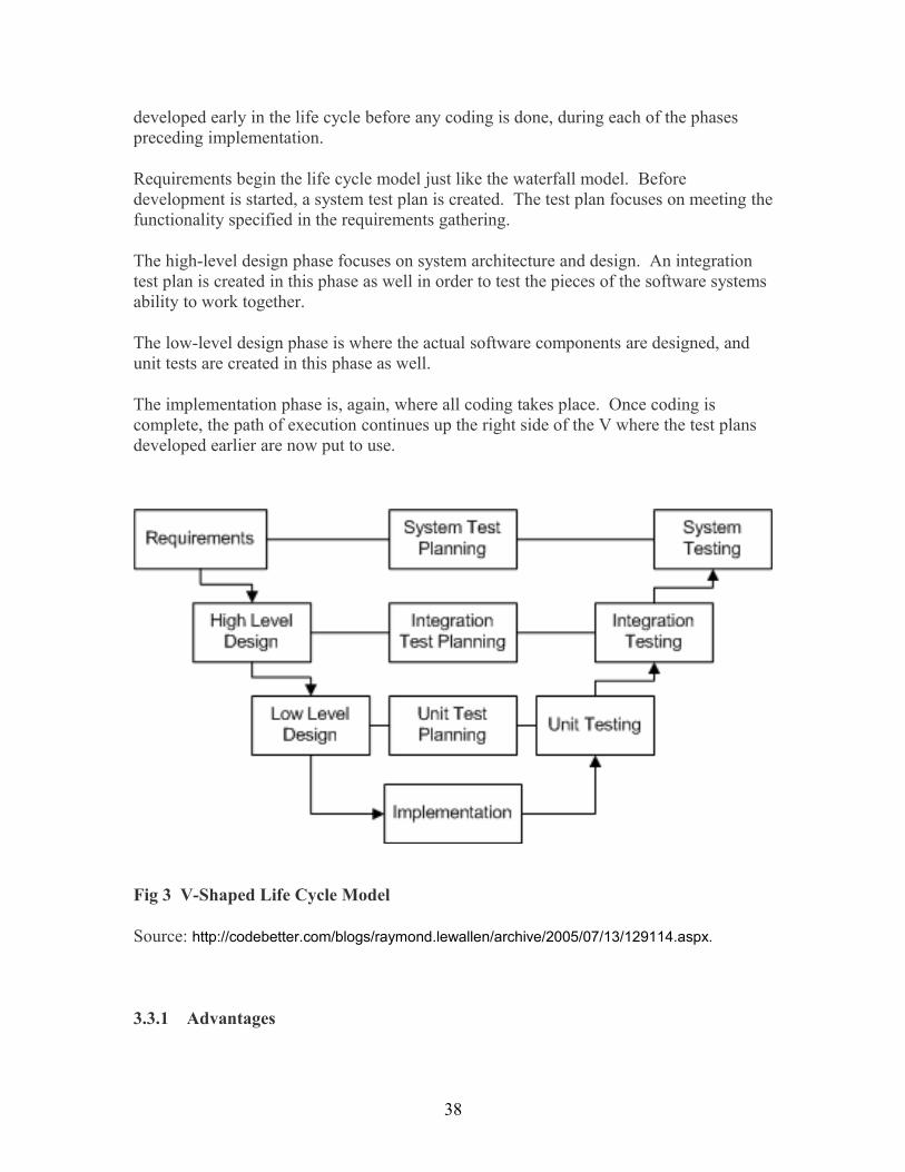
developed early in the life cycle before any coding is done, during each of the phases preceding implementation.
Requirements begin the life cycle model just like the waterfall model. Before development is started, a system test plan is created. The test plan focuses on meeting the functionality specified in the requirements gathering.
The high-level design phase focuses on system architecture and design. An integration test plan is created in this phase as well in order to test the pieces of the software systems ability to work together.
The low-level design phase is where the actual software components are designed, and unit tests are created in this phase as well.
The implementation phase is, again, where all coding takes place. Once coding is complete, the path of execution continues up the right side of the V where the test plans developed earlier are now put to use.
Fig 3 V-Shaped Life Cycle Model
Source: http://codebetter.com/blogs/raymond.lewallen/archive/2005/07/13/129114.aspx.
3.3.1 Advantages
38

• Simple and easy to use. • Each phase has specific deliverables. • Higher chance of success over the waterfall model due to the development of test
plans early on during the life cycle. • Works well for small projects where requirements are easily understood.
3.3.2 Disadvantages
• Very rigid, like the waterfall model. • Little flexibility and adjusting scope is difficult and expensive. • Software is developed during the implementation phase, so no early prototypes of
the software are produced. • Model doesn’t provide a clear path for problems discovered during testing phases.
3.4 Incremental Model
The incremental model is an intuitive approach to the waterfall model. It is a kind of a “multi-waterfall” cycle. In that multiple development cycles take at this point. Cycles are broken into smaller, more easily managed iterations. Each of the iterations goes through the requirements, design, implementation and testing phases.
The first iteration produces a working version of software and this makes possible to have working software early on during the software life cycle. Subsequent iterations build on the initial software produced during the first iteration.
Incremental Life Cycle Model
Fig 4 Incremental Life Cycle Model
Source: http://codebetter.com/blogs/raymond.lewallen/archive/2005/07/13/129114.aspx.
3.4.1 Advantages
• Generates working software quickly and early during the software life cycle.
39

• More flexible – inexpensive to change scope and requirements. • Easier to test and debug during a smaller iteration. • Easier to manage risk because risky pieces are identified and handled during its
iteration. • Each of the iterations is an easily managed landmark
3.4.2 Disadvantages
• Each phase of an iteration is rigid and do not overlap each other. • Problems as regard to system architecture may arise as a result of inability to
gathered requirements up front for the entire software life cycle.
3.5 Spiral Model
The spiral model is similar to the incremental model, with more emphases placed on risk analysis. The spiral model has four phases namely Planning, Risk Analysis, Engineering and Evaluation. A software project continually goes through these phases in iterations which are called spirals. In the baseline spiral requirements are gathered and risk is assessed. Each subsequent spiral builds on the baseline spiral.
Requirements are gathered during the planning phase. In the risk analysis phase, a process is carried out to discover risk and alternate solutions. A prototype is produced at the end of the risk analysis phase.
Software is produced in the engineering phase, alongside with testing at the end of the phase. The evaluation phase provides the customer with opportunity to evaluate the output of the project to date before the project continues to the next spiral.
In the spiral model, the angular component denotes progress, and the radius of the spiral denotes cost.
Spiral Life Cycle Model
40

Fig 5 Spiral Life Cycle Model
Source: http://codebetter.com/blogs/raymond.lewallen/archive/2005/07/13/129114.aspx.
3.5.1 Merits
• High amount of risk analysis • Good for large and mission-critical projects. • Software is produced early in the software life cycle.
3.5.2 Demerits
• Can be a costly model to use. • Risk analysis requires highly specific expertise. • Project’s success is highly dependent on the risk analysis phase. • Doesn’t work well for smaller projects.
3.6 Requirements Phase
41

Business requirements are gathered in this phase. This phase is the main center of attention of the project managers and stake holders. Meetings with managers, stake holders and users are held in order to determine the requirements. Th general questions that require answers during a requirements gathering phase are: Who is going to use the system? How will they use the system? What data should be input into the system? What data should be output by the system? A list of functionality that the system should provide, which describes functions the system should perform, business logic that processes data, what data is stored and used by the system, and how the user interface should work is produced at this point. The requirements development phase may have been preceded by a feasibility study, or a conceptual analysis phase of the project. The requirements phase may be divided into requirements elicitation (gathering the requirements from stakeholders), analysis (checking for consistency and completeness), specification (documenting the requirements) and validation (making sure the specified requirements are correct)
In systems engineering, a requirement can be a description of what a system must do, referred to as a Functional Requirement. This type of requirement specifies something that the delivered system must be able to do. Another type of requirement specifies something about the system itself, and how well it performs its functions. Such requirements are often called Non-functional requirements, or 'performance requirements' or 'quality of service requirements.' Examples of such requirements include usability, availability, reliability, supportability, testability, maintainability, and (if defined in a way that's verifiably measurable and unambiguous) ease-of-use.
3.6.1 Types of Requirements
Requirements are categorised as:
• Functional requirements which describe the functionality that the system is to execute; for example, formatting some text or modulating a signal.
• Non-functional requirements which are the ones that act to constrain the solution. Nonfunctional requirements are sometimes known as quality requirements or Constraint requirements No matter how the problem is solved the constraint requirements must be adhered to.
It is important to note that functional requirements can be directly implemented in software. The non-functional requirements are controlled by other aspects of the system. For example, in a computer system reliability is related to hardware failure rates, performance controlled by CPU and memory. Non-functional requirements can in some cases be broken into functional requirements for software. For example, a system level non-functional safety requirement can be decomposed into one or more functional requirements. In addition, a non-functional requirement may be converted into a process requirement when the requirement is not easily measurable. For example, a system level
42

maintainability requirement may be decomposed into restrictions on software constructs or limits on lines or code.
3.6.2 Requirements analysis
Requirements analysis in systems engineering and software engineering, consist of those activities that go into determining the needs or conditions to meet for a new or altered product, taking account of the possibly conflicting requirements of the various stakeholders, such as beneficiaries or users.
Requirements analysis is critical to the success of a development project. Requirements must be actionable, measurable, testable, related to identified business needs or opportunities, and defined to a level of detail sufficient for system design.
3.6.3 The Need for Requirements Analysis Studies reveal that insufficient attention to Software Requirements Analysis at the beginning of a project is the major reason for critically weak projects that often do not fulfil basic tasks for which they were designed. Software companies are now spending time and resources on effective and streamlined Software Requirements Analysis Processes as a condition to successful projects that support the customer’s business goals and meet the project’s requirement specifications.3.6.4 Requirements Analysis Process: Requirements Elicitation, Analysis And
SpecificationRequirements Analysis is the process of understanding the client needs and expectations from a proposed system or application. It is a well-defined stage in the Software Development Life Cycle model. Requirements are a description of how a system should behave, in other words, a description of system properties or attributes. Considering the numerous levels of dealings between users, business processes and devices in worldwide corporations today, there are immediate and composite requirements from a single application, from different levels within an organization and outside it The Software Requirements Analysis Process involves the complex task of eliciting and documenting the requirements of all customers, modelling and analyzing these requirements and documenting them as a foundation for system design.This job (requirements analysis process) is dedicated to a specialized Requirements Analyst. The Requirements Analysis function may also come under the scope of Project Manager, Program Manager or Business Analyst, depending on the organizational hierarchy.
3.6.5 Steps in the Requirements Analysis Process
43

3.6.5.1 Fix system boundariesThis is initial step and helps in identifying how the new application fit in into the business processes, how it fits into the larger picture as well as its capacity and limitations.3.6.5.2 Identify the customerThis focuses on identifying who the ‘users’ or ‘customers’ of an application are that is to say knowing the group or groups of people who will be directly or indirectly impacted by the new application. This allows the Requirements Analyst to know in advance where he has to look for answers.
3.6.5.3 Requirements elicitationHere information is gathered from the multiple stakeholders identified. The Requirements Analyst brings out from each of these groups what their requirements from the application are and what they expect the application to achieve. Taking into account the multiple stakeholders involved, the list of requirements gathered in this manner could go into pages. The level of detail of the requirements list depends on the number and size of user groups, the degree of complexity of business processes and the size of the application.
3.6.5.3.1 Problems faced in Requirements Elicitation• Ambiguous understanding of processes • Inconsistency within a single process by multiple users • Insufficient input from stakeholders • Conflicting stakeholder interests • Changes in requirements after project has begun
3.6.5.3.2 Tools used in Requirements ElicitationTools used in Requirements Elicitation include stakeholder interviews and focus group studies. Other methods like flowcharting of business processes and the use of existing documentation like user manuals, organizational charts, process models and systems or process specifications, on-site analysis, interviews with end-users, market research and competitor analysis are also used widely in Requirements Elicitation.There are of course, modern tools that are better equipped to handle the complex and multilayered process of Requirements Elicitation. Some of the current Requirements Elicitation tools in use are:• Prototypes • Use cases • Data flow diagrams • Transition process diagrams
44

• User interfaces
3.6.5.4 Requirements Analysis The moment all stakeholder requirements have been gathered, a structured analysis of these can be done after modeling the requirements. Some of the Software Requirements Analysis techniques used are requirements animation, automated reasoning, knowledge-based critiquing, consistency checking, analogical and case-based reasoning.3.6.5.5. Requirements Specification After requirements have been elicited, modeled and analyzed, they should be documented in clear, definite terms. A written requirements document is crucial and as such its circulation should be among all stakeholders including the client, user-groups, the development and testing teams. It has been observed that a well-designed, clearly documented Requirements Specification is vital and serves as a:• Base for validating the stated requirements and resolving stakeholder conflicts, if any • Contract between the client and development team • Basis for systems design for the development team • Bench-mark for project managers for planning project development lifecycle and
goals • Source for formulating test plans for QA and testing teams • Resource for requirements management and requirements tracing • Basis for evolving requirements over the project life span Software requirements specification involves scoping the requirements so that it meets the customer’s vision. It is the result of teamwork between the end-user who is usually not a technical expert, and a Technical/Systems Analyst, who is expected to approach the situation in technical terms.The software requirements specification is a document that lists out stakeholders’ needs and communicates these to the technical community that will design and build the system. It is really a challenge to communicate a well-written requirements specification, to both these groups and all the sub-groups within. To overcome this, Requirements Specifications may be documented separately as: • User Requirements - written in clear, precise language with plain text and use cases,
for the benefit of the customer and end-user • System Requirements - expressed as a programming or mathematical model, meant
to address the Application Development Team and QA and Testing Team. Requirements Specification serves as a starting point for software, hardware and database design. It describes the function (Functional and Non-Functional specifications) of the system, performance of the system and the operational and user-interface constraints that will govern system development.
45

3.7 Requirements ManagementRequirements Management is the all-inclusive process that includes all aspects of software requirements analysis and as well ensures verification, validation and traceability of requirements. Effective requirements management practices assure that all system requirements are stated unmistakably, that omissions and errors are corrected and that evolving specifications can be included later in the project lifecycle.
3.7 Design Phase
The software system design is formed from the results of the requirements phase. This is where the details on how the system will work are produced. Deliverables in this phase include hardware and software, communication, software design.
3.8 Definition of software design
A software design is a meaningful engineering representation of some software product that is to be built. A design can be traced to the customer's requirements and can be assessed for quality against predefined criteria. In the software engineering context, design focuses on four major areas of concern: data, architecture, interfaces and components.
The design process is very important. As a labourer, for example one would not attempt to build a house without an approved blueprint so as not to risk the structural integrity and customer satisfaction. In the same way, the approach to building software products is no unlike. The emphasis in design is on quality. It is pertinent to note that, this is the only phase in which the customer’s requirements can be precisely translated into a finished software product or system. As such, software design serves as the foundation for all software engineering steps that follow regardless of which process model is being employed.
During the design process the software specifications are changed into design models that express the details of the data structures, system architecture, interface, and components. Each design product is re-examined for quality before moving to the next phase of software development. At the end of the design process a design specification document is produced. This document is composed of the design models that describe the data, architecture, interfaces and components.
3.9 Design Specification Models
• Data design – created by changing the analysis information model (data dictionary and ERD) into data structures needed to implement the software. Part of the data design may occur in combination with the design of software architecture. More detailed data design occurs as each software component is designed.
46

• Architectural design - defines the relationships among the major structural elements of the software, the “design patterns” that can be used to attain the requirements that have been defined for the system, and the constraint that affect the way in which the architectural patterns can be applied. It is derived from the system specification, the analysis model, and the subsystem interactions defined in the analysis model (DFD).
• Interface design - explains how the software elements communicate with each other, with other systems, and with human users. Much of the necessary information required is provided by the e data flow and control flow diagrams.
• Component-level design – It converts the structural elements defined by the software architecture into procedural descriptions of software components using information acquired from the process specification (PSPEC), control specification (CSPEC), and state transition diagram (STD).
3.10 Design Guidelines
In order to assess the quality of a design (representation) the yardstick for a good design should be established. Such a design should:
• exhibit good architectural structure • be modular • contain distinct representations of data, architecture, interfaces, and components
(modules) • lead to data structures that are appropriate for the objects to be implemented and
be drawn from recognizable design patterns • lead to components that exhibit independent functional characteristics • lead to interfaces that reduce the complexity of connections between modules and
with the external environment • be derived using a reputable method that is driven by information obtained during
software requirements analysis
These criteria are not acquired by chance. The software design process promotes good design through the application of fundamental design principles, systematic methodology and through review.
3.11 Design Principles
Software design can be seen as both a process and a model.
“The design process is a series of steps that allow the designer to describe all aspects of the software to be built. However, it is not merely a recipe book; for a competent and successful design, the designer must use creative skill, past experience, a sense of what makes “good” software, and have a commitment to quality.
47
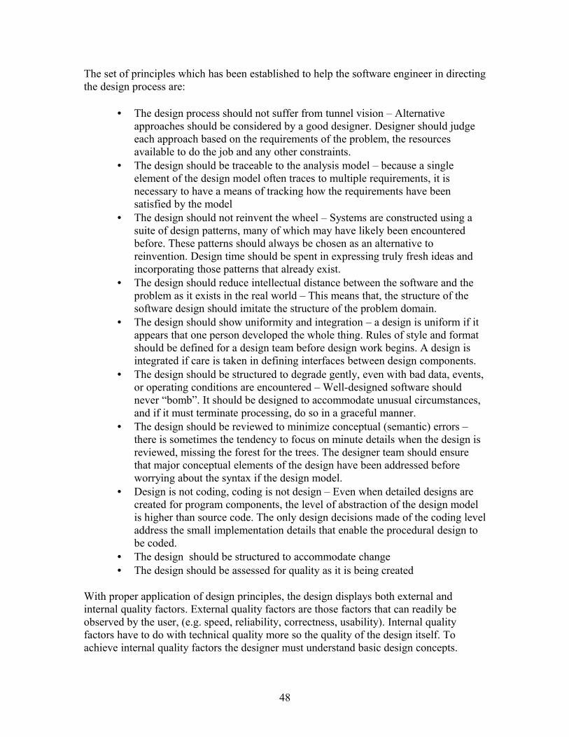
The set of principles which has been established to help the software engineer in directing the design process are:
• The design process should not suffer from tunnel vision – Alternative approaches should be considered by a good designer. Designer should judge each approach based on the requirements of the problem, the resources available to do the job and any other constraints.
• The design should be traceable to the analysis model – because a single element of the design model often traces to multiple requirements, it is necessary to have a means of tracking how the requirements have been satisfied by the model
• The design should not reinvent the wheel – Systems are constructed using a suite of design patterns, many of which may have likely been encountered before. These patterns should always be chosen as an alternative to reinvention. Design time should be spent in expressing truly fresh ideas and incorporating those patterns that already exist.
• The design should reduce intellectual distance between the software and the problem as it exists in the real world – This means that, the structure of the software design should imitate the structure of the problem domain.
• The design should show uniformity and integration – a design is uniform if it appears that one person developed the whole thing. Rules of style and format should be defined for a design team before design work begins. A design is integrated if care is taken in defining interfaces between design components.
• The design should be structured to degrade gently, even with bad data, events, or operating conditions are encountered – Well-designed software should never “bomb”. It should be designed to accommodate unusual circumstances, and if it must terminate processing, do so in a graceful manner.
• The design should be reviewed to minimize conceptual (semantic) errors – there is sometimes the tendency to focus on minute details when the design is reviewed, missing the forest for the trees. The designer team should ensure that major conceptual elements of the design have been addressed before worrying about the syntax if the design model.
• Design is not coding, coding is not design – Even when detailed designs are created for program components, the level of abstraction of the design model is higher than source code. The only design decisions made of the coding level address the small implementation details that enable the procedural design to be coded.
• The design should be structured to accommodate change • The design should be assessed for quality as it is being created
With proper application of design principles, the design displays both external and internal quality factors. External quality factors are those factors that can readily be observed by the user, (e.g. speed, reliability, correctness, usability). Internal quality factors have to do with technical quality more so the quality of the design itself. To achieve internal quality factors the designer must understand basic design concepts.
48

3.12 Fundamental Software Design Concepts
Over the past four decades, a set of fundamental software design concepts has evolved, each providing the software designer with a foundation from which more sophisticated design methods can be applied. Each concept assists the soft ware engineer to answer the following questions:
• What criteria can be used to partition software into individual components?
• How is function or data structure detail separated from a conceptual representation of software?
• Are there uniform criteria that define the technical quality of a software design?
The fundamental design concepts are:
• Abstraction - allows designers to focus on solving a problem without being concerned about irrelevant lower level details (procedural abstraction - named sequence of events, data abstraction - named collection of data objects)
• Refinement - process of elaboration where the designer provides successively more detail for each design component
• Modularity - the degree to which software can be understood by examining its components independently of one another
• Software architecture - overall structure of the software components and the ways in which that structure provides conceptual integrity for a system
• Control hierarchy or program structure - represents the module organization and implies a control hierarchy, but does not represent the procedural aspects of the software (e.g. event sequences)
• Structural partitioning - horizontal partitioning defines three partitions (input, data transformations, and output); vertical partitioning (factoring) distributes control in a top-down manner (control decisions in top level modules and processing work in the lower level modules).
• Data structure - representation of the logical relationship among individual data elements (requires at least as much attention as algorithm design)
• Software procedure - precise specification of processing (event sequences, decision points, repetitive operations, data organization/structure)
• Information hiding - information (data and procedure) contained within a module is inaccessible to modules that have no need for such information
Activity G 1 What are the steps in requirement Analysis process?2 What are the fundamental design concepts ?
49

4.0 ConclusionSoftware life cycle models describe phases of the software cycle and the order in which those phases are executed.
5.0 Summary
In this unit, we have learnt that:
• Software life cycle models describe phases of the software cycle and the order in which those phases are executed. .
• In general model, each phase produces deliverables required by the next phase in the life cycle. Requirements are translated into design. Code is produced during implementation that is driven by the design. Testing verifies the deliverable of the implementation phase against requirements.
• In a waterfall model, each phase must be completed in its entirety before the next phase can begin. At the end of each phase, a review takes place to determine if the project is on the right path and whether or not to continue or discard the project. Unlike what I mentioned in the general model, phases do not overlap in a waterfall model.
• Just like the waterfall model, the V-Shaped life cycle is a sequential path of execution of processes. Each phase must be completed before the next phase begins. Testing is emphasized in this model more so than the waterfall model though. The testing procedures are developed early in the life cycle before any coding is done, during each of the phases preceding implementation.
• The incremental model is an intuitive approach to the waterfall model. Multiple development cycles take place here, making the life cycle a “multi-waterfall” cycle. Cycles are divided up into smaller, more easily managed iterations. Each iteration passes through the requirements, design, implementation and testing phases.
• The spiral model is similar to the incremental model, with more emphases placed on risk analysis. The spiral model has four phases: Planning, Risk Analysis, Engineering and Evaluation. A software project repeatedly passes through these phases in iterations (called Spirals in this model). The baseline spirals, starting in the planning phase, requirements are gathered and risk is assessed. Each subsequent spirals builds on the baseline spiral.
• In requirement phase business requirements are gathered and that the phase is the main focus of the project managers and stake holders.
• The software system design is produced from the results of the requirements phase and it is the phase is where the details on how the system will work is produced
6.0 Tutor Marked Assignment
50

1 What is software life cycle model?2 Explain the general model3 Compare and contrast General and Waterfall Models4 Explain V-Shaped Life Cycle Model5 Explain Incremental Model6 Compare and contrast Incremental and Spiral Models7 Discus the requirement and design phases
7.0 Further Reading And Other Resources
Blanchard, B. S., & Fabrycky, W. J.(2006) Systems engineering and analysis (4th ed.) New Jersey: Prentice Hall.
Ummings, Haag (2006). Management Information Systems for the Information Age. Toronto, McGraw-Hill Ryerson
Unit 3 Modularity
1.0 Introduction
In unit 2 we discussed about software lifecycle models in general and also in detailed the requirement and the design phases of software development. In this unit we will look at Modudularity in programming.
51
2.0 Objectives
By the end of this unit, you should be able to:• Define Modularity• Differentiate between logical and physical modularity• Explain benefits of modular design • Explain approaches of writing modular program• Explain Criteria for using modular design• Outlines the attributes of a good module • Outline the steps to creating effective module • Differentiate between Top-down and Bottom-up programming approach
What is Modularity?
Modularity is a general systems concept which is the degree to which a system’s components may be separated and recombined. It refers to both the tightness of coupling between components, and the degree to which the “rules” of the system architecture enable (or prohibit) the mixing and matching of components
The concept of modularity in computer software has been promoted for about five decades. In essence, the software is divided into separately names and addressable components called modules that are integrated to satisfy problem requirements. It is important to note that a reader cannot easily understand large programs with a single module. The number of variables, control paths and sheer complexity make understanding almost impossible. As a result a modular approach will allow for the software to be intellectually manageable. However, it is important to note that software cannot be subdivided indefinitely so as to make the effort required to understand or develop it negligible. This is because the more the number of modules, the less the effort to develop them.
3.14 Logical Modularity
Generally in software, modularity can be categorized as logical or physical. Logical Modularity is concerned with the internal organization of code into logically-related units. In modern high level languages, logical modularity usually starts with the class, the smallest code group that can be defined. In languages such as Java and C#, classes can be further combined into packages which allow developers to organize code into group of related classes. Depending on the environment, a module can be implemented as a single class, several classes in a package, or an entire API (a collection of packages). You should be able to describe the functionality of tour module in a single sentence (i.e. this module calculates tax per zip code) regardless of the implementation scale of your module,). Your module should expose its functionality as simple interfaces that shield callers from all implementation details. The functionality of a module should be accessible through a published interface that allows the module to expose its
52

functionalities to the outside world while hiding its implementation details.
3.15 Physical Modularity
Physical Modularity is probably the earliest form of modularity introduced in software creation. Physical modularity consists of two main components namely: (1) a file that contains compiled code and other resources and (2) an executing environment that understand how to execute the file. Developers build and assemble their modules into compiled assets that can be distributed as single or multiple files. In Java for example, the jar file is the unit of physical modularity for code distribution (.Net has the assembly). The file and its associated meta-data are designed to be loaded and executed by the run time environment that understands how to run the compiled code.Physical modularity can also be affected by the context and scale of abstraction. Within Java, for instance, the developer community has created and accept several physical modularity strategies to address different aspects of enterprise development 1) WAR for web components 2) EJB for distributed enterprise components 3) EAR for enterprise application components 4) vendor specific modules such as JBoss Service Archive (SAR). These are usually a variation of the JAR file format with special meta data to target the intended runtime environment. The current trend of adoption seems to be pointing to OSGi as a generic physical module format. OSGi provides the Java environment with additional functionalties that should allow developers to model their modules to scale from small emddeable to complex enterprise components (a lofty goal in deed).
3.16 Benefits of Modular Design
• Scalable Development: a modular design allows a project to be naturally subdivided along the lines of its modules. A developer (or groups of developers) can be assigned a module to implement independently which can produce an asynchronous project flow.
• Testable Code Unit: when your code is partition into functionally-related chunks, it facilitates the testing of each module independently. With the proper testing framework, developers can exercise each module (and its constituencies) without having to bring up the entire project.
• Build Robust System: in the monolithic software design, as your system grows in complexity so does its propensity to be brittle (changes in one section causes failure in another). Modularity lets you build complex system composed of smaller parts that can be independently managed and maintained. Fixes in one portion of the code does not necessarily affect the entire system.
• Easier Modification & Maintenance: post-production system maintenance is another crucial benefit of modular design. Developers have the ability to fix and make non-infrastructural changes to module without affecting other modules. The updated module can independently go through the build and release cycle without the need to re-build and redeploy the entire system.
53

• Functionally Scalable: depending on the level of sophistication of your modular design, it's possible to introduce new functionalities with little or no change to existing modules. This allows your software system to scale in functionality without becoming brittle and a burden on developers.
3.17 Approaches of writing Modular program
The three basic approaches of designing Modular program are:
• Process-oriented design
This approach places the emphasis on the process with the objective being to design modules that have high cohesion and low coupling. (Data flow analysis and data flow diagrams are often used.)
• Data-oriented design
In this approach the data comes first. That is the structure of the data is determined first and then procedures are designed in a way to fit to the structure of the data.
• Object-oriented design
In this approach, the objective is to first identify the objects and then build the product around them. In concentrate, this technique is both data- and process-oriented.
3.18 Criteria for using Modular Design
• Modular decomposability – If the design method provides a systematic means for breaking problem into sub problems, it will reduce the complexity of the overall problem, thereby achieving a modular solution.
• Modular compos ability - If the design method enables existing (reusable) design components to be assembled into a new system, it will yield a modular solution that does not reinvent the wheel.
• Modular understand ability – If a module can be understood as a stand-alone unit (without reference to other modules) it will be easier to build and easier to change.
• Modular continuity – If small changes to the system requirements result in changes to individual modules, rather than system-wide changes, the impact of change-induced side-effects will be minimised
• Modular protection – If an abnormal condition occurs within a module and its effects are constrained within that module, then impact of error-induced side-effects are minimised
54

3.19 Attributes of a good Module
• Functional independence - modules have high cohesion and low coupling • Cohesion - qualitative indication of the degree to which a module focuses on just
one thing • Coupling - qualitative indication of the degree to which a module is connected to
other modules and to the outside world
3.20 Steps to Creating Effective Module
• Evaluate the first iteration of the program structure to reduce coupling and improve cohesion. Once program structure has been developed modules may be exploded or imploded with aim of improving module independence.
o An exploded module becomes two or more modules in the final program structure.
o An imploded module is the result of combining the processing implied by two or more modules.
An exploded module normally results when common processing exists in two or more modules and can be redefined as a separate cohesive module. When high coupling is expected, modules can sometimes be imploded to reduce passage of control, reference to global data and interface complexity.
• Attempt to minimise structures with high fan-out; strive for fan-in as structure depth increases. The structure shown inside the cloud in Fig. 3 does not make effective use of factoring.
55

Fig 6 Example of a program structure
• Keep the scope of effect of a module within the scope of control for that module. o The scope of effect of a module is defined as all other modules that are
affected by a decision made by that module. For example, the scope of control of module e is all modules that are subordinate i.e. modules f, g, h, n, p and q.
• Evaluate module interfaces to reduce complexity, reduce redundancy, and
improve consistency. o Module interface complexity is a prime cause of software errors.
Interfaces should be designed to pass information simply and should be consistent with the function of a module. Interface inconsistency (i.e. seemingly unrelated data passed via an argument list or other technique) is an indication of low cohesion. The module in question should be re-evaluated.
• Define modules whose function is predictable and not overly restrictive (e.g. a
module that only implements a single task). o A module is predictable when it can be treated as a black box; that is, the
same external data will be produced regardless of internal processing details. Modules that have internal “memory” can be unpredictable unless care is taken in their use.
o A module that restricts processing to a single task exhibits high cohesion and is viewed favourably by a designer.
56

• Strive for controlled entry modules, avoid pathological connection (e.g. branches
into the middle of another module) o This warns against content coupling. Software is easier to understand and
maintain if the module interfaces are constrained and controlled.
3.21 Programming Languages that formally support module concept
Languages that formally support the module concept include IBM/360 Assembler, COBOL, RPG and PL/1, Ada, D, F, Fortran, Haskell, OCaml, Pascal, ML, Modula-2, Erlang, Perl, Python and Ruby. The IBM System i also uses Modules in RPG, COBOL and CL, when programming in the ILE environment. Modular programming can be performed even where the programming language lacks explicit syntactic features to support named modules.
Software tools can create modular code units from groups of components. Libraries of components built from separately compiled modules can be combined into a whole by using a linker.
3.22 Module Interconnection Languages
Module interconnection languages (MILs) provide formal grammar constructs for deciding the various module interconnection specifications required to assemble a complete software system. MILs enable the separation between programming-in-the-small and programming-in-the-large. Coding a module represents programming in the small, while assembling a system with the help of a MIL represents programming in the large. An example of MIL is MIL-75.
3.23 Top-Down Design
Top-down is a programming style, the core of traditional procedural languages, in which design begins by specifying complex pieces and then dividing them into successively smaller pieces. Finally, the components are precise enough to be coded and the program is written. It is the exact opposite of the bottom-up programming approach which is common in object-oriented languages such as C++ or Java.
The method of writing a program using top-down approach is to write a main procedure that names all the major functions it will need. After that the programming team examines the requirements of each of those functions and repeats the process. These compartmentalized sub-routines finally will perform actions so straightforward they can be easily and concisely coded. The program is done when all the various sub-routines have been coded.
57

Merits of top-down programming:
• Separating the low level work from the higher level abstractions leads to a modular design.
• Modular design means development can be self contained. • Having "skeleton" code illustrates clearly how low level modules integrate. • Fewer operations errors • Much less time consuming (each programmer is only concerned in a part of the
big project). • Very optimized way of processing (each programmer has to apply their own
knowledge and experience to their parts (modules), so the project will become an optimized one).
• Easy to maintain (if an error occurs in the output, it is easy to identify the errors generated from which module of the entire program).
3.24 Bottom-up approach
In a bottom-up approach the individual base elements of the system are first specified in great detail. These elements are then connected together to form bigger subsystems, which are linked, sometimes in many levels, until a complete top-level system is formed. This strategy often resembles a "seed" model, whereby the beginnings are small, but eventually grow in complexity and completeness.
Object-oriented programming (OOP) is a programming paradigm that uses "objects" to design applications and computer programs.
. This bottom-up approach has one drawback. We need to use a lot of perception to decide the functionality that is to be provided by the module. This approach is more suitable if a system is to be developed from existing system, because it starts from some existing modules. Modern software design approaches usually mix both top-down and bottom-up approaches.
Activity H What are the steps to create effective modules?
4.0 Conclusion
The benefits of modular programming cannot be overemphasised. It among other things, allows for scalar development, it facilitates code testing, helps in building robust system, allows for easier modification and maintenance.
5.0 Summary
In this unit, we have learnt that:
58

• Modularity is a general systems concept, the degree to which a system’s components may be separated and recombined. It refers to both the tightness of coupling between components, and the degree to which the “rules” of the system architecture enable (or prohibit) the mixing and matching of components
• Physical Modularity is probably the earliest form of modularity introduced in software creation. Physical modularity consists of two main components namely: (1) a file that contains compiled code and other resources and (2) an executing environment that understand how to execute the file. Developers build and assemble their modules into compiled assets that can be distributed as single or multiple files.
• Logical Modularity is concerned with the internal organization of code into logically-related units.
• Modular programming is beneficial in that:It allows for scalar development, it facilitates code testing, helps in building robust system, allows for easier modification and maintenance.
• The three basic approaches of designing Modular program are: Process-oriented design, Data-oriented design and Object-oriented design.
• Criteria for using Modular Design include: Modular decomposability, Modular compos ability, Modular understand ability, Modular continuity, and Modular protection.
• Attributes of a good Module include: Functional independence, Cohesion, and Coupling
• Steps to Creating Effective Module include: Evaluate the first iteration of the program structure to reduce coupling and improve cohesion, Attempt to minimise structures with high fan-out; strive for fan-in as structure depth increases, Define modules whose function is predictable and not overly restrictive (e.g. a module that only implements a single task), Strive for controlled entry modules, avoid pathological connection (e.g. branches into the middle of another module)
• Top-down is a programming style, the core of traditional procedural languages, in which design begins by specifying complex pieces and then dividing them into successively smaller pieces. Finally, the components are precise enough to be coded and the program is written.
• In a bottom-up approach the individual base elements of the system are first specified in great detail. These elements are then connected together to form bigger subsystems, which are linked, sometimes in many levels, until a complete top-level system is formed
6.0 Tutor Marked Assignment
• What is Modularity?• Differentiate between logical and physical modularity• What are the benefits of modular design • Explain the approaches of writing modular program
59

• What are the Criteria for using modular design• Outlines the attributes of a good module • Outline the steps to creating effective module • Differentiate between Top-down and Bottom-up programming approach
7.0 Futher Reading And Other Resouces
Laplante, Phil (2009). Requirements Engineering for Software and Systems (1st ed.). Redmond, WA: CRC Press. ISBN 1-42006-467-3. http://beta.crcpress.com/product/isbn/9781420064674.
McConnell, Steve (1996). Rapid Development: Taming Wild Software Schedules (1st ed.). Redmond, WA: Microsoft Press. ISBN 1-55615-900-5. http://www.stevemcconnell.com/.
Wiegers, Karl E. (2003). Software Requirements 2: Practical techniques for gathering and managing requirements throughout the product development cycle (2nd ed.). Redmond: Microsoft Press. ISBN 0-7356-1879-8.
Andrew Stellman and Jennifer Greene (2005). Applied Software Project Management. Cambridge, MA: O'Reilly Media. ISBN 0-596-00948-8. http://www.stellman-greene.com.
Unit 4 Pseudo code
1.0 Introduction
In the last unit, you have learnt about Modudularity in programming. Its benefits, design approaches and criteria, attributes of a good Module and the steps to creating effective module. You equally learnt about Top-Down and Bottom-up approaches in programming. This unit ushers you into Pseudo code a way to create a logical structure
60

that will describing the actions, which will be executed by the application. After studying this unit you are expected to have achieved the following objectives listed below.
2.0 Objectives
By the end of this unit, you should be able to:• Define Pseudo code• Explain General guidelines for writing Pseudo code. • Give examples of Pseudo codes
3.26 Definition of Pseudo codePseudo-code is a non-formal language, a way to create a logical structure, describing the actions, which will be executed by the application. Using pseudo-code, the developer shows the application logic using his local language, without applying the structural rules of a specific programming language. The big advantage of the pseudo-code is that the application logic can be easily comprehended by any developer in the development team. In addition, when the application algorithm is expressed in pseudo-code, it is very easy to convert the pseudo-code into real code (using any programming language).
3.26 General guidelines for writing Pseudo code
Here are a few general guidelines for writing your pseudo code:Mimic good code and good English. Using aspects of both systems means
adhering to the style rules of both tosome degree. It is still important that variable names be mnemonic, comments be included where useful, and Englishphrases be comprehensible (full sentences are usually not necessary).
Ignore unnecessary details. If you are worrying about the placement of commas, you are using too much detail. It is agood idea to use some convention to group statements (begin/end, brackets, or whatever else is clear), but you shouldn'tobsess about syntax.
Don't belabor the obvious. In many cases, the type of a variable is clear from context; unless it is critical that it is specified to be an integer or real, it is often unnecessary to make it explicit.
Take advantage of programming shorthands. Using if-then-else or looping structures is more concise than writingout the equivalent in English; general constructs that are not peculiar to a small number of languages are good candidatesfor use in pseudocode. Using parameters in specifying procedures is concise, clear, and accurate, and hence should notbe omitted from pseudocode.
Consider the context. If you are writing an algorithm for quicksort, the statement use quicksort to sort the values ishiding too much detail; if you have already studied quicksort in a class and later use it as a subroutine in another
61

algorithm, the statement would be appropriate to use.Don't lose sight of the underlying model. It should be possible to see through"
your pseudocode to the model below;if not (that is, you are not able to analyze the algorithm easily), it is written at too high a level.
Check for balance. If the pseudocode is hard for a person to read or difficult to translate into working code (or worseyet, both!), then something is wrong with the level of detail you have chosen to use.
3.27 Examples of Pseudocode
Example 1 - Computing Sales Value Added (VAT) Tax : Pseudo-code the task of computing the final price of an item after figuring in sales tax. Note the three types of instructions: input (get), process/calculate (=) and output (display)
1. get price of item2. get VAT rate3. VAT = price of time times VAT rate4 final price = price of item plus VAT5. display final price6. stop
Variables: price of item, sales tax rate, sales tax, final price
Note that the operations are numbered and each operation is unambiguous and effectively computable. We also extract and list all variables used in our pseudo-code. This will be useful when translating pseudo-code into a programming language
Example 2 - Computing Weekly Wages: Gross pay depends on the pay rate and the number of hours worked per week. However, if you work more than 50 hours, you get paid time-and-a-half for all hours worked over 50. Pseudo-code the task of computing gross pay given pay rate and hours worked.
1. get hours worked2. get pay rate3. if hours worked ≤ 50 then3.1 gross pay = pay rate times hours worked4. else4.1 gross pay = pay rate times 50 plus 1.5 times pay rate times (hours
worked minus 50)5. display gross pay
62

6. halt
variables: hours worked, ray rate, gross pay
This example presents the conditional control structure. On the basis of the true/false question asked in line 3, line 3.1 is executed if the answer is True; otherwise if the answer is False the lines subordinate to line 4 (i.e. line 4.1) is executed. In both cases pseudo-code is resumed at line 5.
Example 3 - Computing a Question Average: Pseudo-code a routine to calculate your question average.
1. get number of questions2. sum = 03. count = 04. while count < number of questions
4.1 get question grade4.2 sum = sum + question grade4.3 count = count + 1
5. average = sum / number of question6. display average7. stop
variables: number of question, sum ,count, question grade, average
This example presents an iterative control statement. As long as the condition in line 4 is True, we execute the subordinate operations 4.1 - 4.3. When the condition is False, we return to the pseudo-code at line 5.
This is an example of a top-test or while do iterative control structure. There is also a bottom-test or repeat until iterative control structure which executes a block of statements until the condition tested at the end of the block is False.
Some Keywords That Should be Used
For looping and selection, The keywords that are to be used include Do While...EndDo; Do Until...Enddo; Case...EndCase; If...Endif; Call ... with (parameters); Call; Return ....; Return; When; Always use scope terminators for loops and iteration.
As verbs, use the words Generate, Compute, Process, etc. Words such as set, reset, increment, compute, calculate, add, sum, multiply, ... print, display, input, output, edit, test , etc. with careful indentation tend to foster desirable pseudocode.
63

Do not include data declarations in your pseudo code.
Activity I Write a pseudo code to find the average of even number between 1 and 20
4.0 Conclusion
The role of pseudo-code in program design cannot be underestimated. When it used, it is not only that logic of application can easily be understood but it can easily be converted into real code.
5.0 Summary
In this unit, you have learnt about the essence of pseudo code in program design
6.0 Tutor Marked Assignment
• What is Pseudo code• Explain the General guidelines for writing Pseudo code. • Write a Pseudo code to find the average of even number between 1 and 20.
7.0 Futher Reading And Other Resouces
Robertson, L. A. (2003) Simple Program Design: A Step-by-Step Approach. 4th ed. Melbourne: Thomson.
Unit 5 Programming Environment, CASE Tools & HIPO Diagrams
1.0 Introduction
In the last unit, you have learnt about pseudo code. In this unit you will be exposed to Programming Environment, CASE Tools & HIPO Diagrams. After studying this unit you are expected to have achieved the following objectives listed below.
2.0 Objectives By the end of this unit, you should be able to:
• Explain Programming Environment
64

• Discuss Case Tools.• Explain Hipo Diagrams.
3.0 Definition of Programming Environment
Programming environments gives the basic tools and Application Programming Interfaces, or APIs, necessary to construct programs. Programming environments help the creation, modification, execution and debugging of programs. The goal of integrating a programming environment is more than simply building tools that share a common data base and provide a consistent user interface. Altogether, the programming environment appears to the programmer as a single tool; there are no firewalls separating the various functions provided by the environment.
3.1 History of Programming Environment
The history of software tools began with the first computers in the early 1950s that used linkers, loaders, and control programs. In the early 1970s the tools became famous with Unix with tools like grep, awk and make that were meant to be combined flexibly with pipes. The term "software tools" came from the book of the same name by Brian Kernighan and P. J. Plauger. Originally, Tools were simple and light weight. As some tools have been maintained, they have been integrated into more powerful integrated development environments (IDEs). These environments combine functionality into one place, sometimes increasing simplicity and productivity, other times part with flexibility and extensibility. The workflow of IDEs is routinely contrasted with alternative approaches, such as the use of Unix shell tools with text editors like Vim and Emacs.
The difference between tools and applications is unclear. For example, developers use simple databases (such as a file containing a list of important values) all the time as tools. However a full-blown database is usually thought of as an application in its own right.
For many years, computer-assisted software engineering (CASE) tools were preferred. CASE tools emphasized design and architecture support, such as for UML. But the most successful of these tools are IDEs.
The ability to use a variety of tools productively is one quality of a skilled software engineer.
3.2 Types of Programming Environment
Software development tools can be roughly divided into the following categories:
• performance analysis tools • debugging tools • static analysis and formal verification tools
65

• correctness checking tools • memory usage tools • application build tools • integrated development environment
3.3 Forms of Software tools
Software tools come in many forms namely :
• Bug Databases: Bugzilla, Trac, Atlassian Jira, LibreSource, SharpForge • Build Tools: Make, automake, Apache Ant, SCons, Rake, Flowtracer, cmake,
qmake • Code coverage: C++test,GCT, Insure++, Jtest, CCover • Code Sharing Sites: Freshmeat, Krugle, Sourceforge. See also Code search
engines. • Compilation and linking tools: GNU toolchain, gcc, Microsoft Visual Studio,
CodeWarrior, Xcode, ICC
• Debuggers: gdb, GNU Binutils, valgrind. Debugging tools also are used in the process of debugging code, and can also be used to create code that is more compliant to standards and portable than if they were not used.
• Disassemblers: Generally reverse-engineering tools. • Documentation generators: Doxygen, help2man, POD, Javadoc, Pydoc/Epydoc,
asciidoc • Formal methods: Mathematically-based techniques for specification, development
and verification • GUI interface generators • Library interface generators: Swig • Integration Tools
• Memory Use/Leaks/Corruptions Detection: dmalloc, Electric Fence, duma, Insure++. Memory leak detection: In the C programming language for instance, memory leaks are not as easily detected - software tools called memory debuggers are often used to find memory leaks enabling the programmer to find these problems much more efficiently than inspection alone.
• Parser generators: Lex, Yacc • Performance analysis or profiling • Refactoring Browser • Revision control: Bazaar, Bitkeeper, Bonsai, ClearCase, CVS, Git, GNU arch,
Mercurial, Monotone, Perforce, PVCS, RCS, SCM, SCCS, SourceSafe, SVN, LibreSource Synchronizer
• Scripting languages: Awk, Perl, Python, REXX, Ruby, Shell, Tcl • Search: grep, find • Source-Code Clones/Duplications Finding
66

• Source code formatting • Source code generation tools • Static code analysis: C++test, Jtest, lint, Splint, PMD, Findbugs, .TEST • Text editors: emacs, vi, vim
3.4 Integrated development environments
Integrated development environments (IDEs) merge the features of many tools into one complete package. They are usually simpler and make it easier to do simple tasks, such as searching for content only in files in a particular project. IDEs are often used for development of enterprise-level applications.Some examples of IDEs are:
• Delphi • C++ Builder (CodeGear) • Microsoft Visual Studio • EiffelStudio • GNAT Programming Studio • Xcode • IBM Rational Application Developer • Eclipse • NetBeans • IntelliJ IDEA • WinDev • Code::Blocks • Lazarus
3.5 What is CASE Tools?
CASE tools are a class of software that automates many of the activities involved in various life cycle phases. For example, when establishing the functional requirements of a proposed application, prototyping tools can be used to develop graphic models of application screens to assist end users to visualize how an application will look after development. Subsequently, system designers can use automated design tools to transform the prototyped functional requirements into detailed design documents. Programmers can then use automated code generators to convert the design documents into code. Automated tools can be used collectively, as mentioned, or individually. For example, prototyping tools could be used to define application requirements that get passed to design technicians who convert the requirements into detailed designs in a traditional manner using flowcharts and narrative documents, without the assistance of automated design software.
It is the scientific application of a set of tools and methods to a software system which is meant to result in high-quality, defect-free, and maintainable software products. It also refers to methods for the development of information systems together with automated tools that can be used in the software development process.
67

3.6 Types of CASE Tools
Some typical CASE tools are:
• Configuration management tools • Data modeling tools • Model transformation tools • Program transformation tools • Refactoring tools • Source code generation tools, and • Unified Modeling Language
Many CASE tools not only yield code but also generate other output typical of various systems analysis and design methodologies such as:
• data flow diagram • entity relationship diagram • logical schema • Program specification • SSADM. • User documentation
3.7 History of CASE
The term CASE was originally formulated by software company, Nastec Corporation of Southfield, Michigan in 1982 with their original integrated graphics and text editor GraphiText, which also was the first microcomputer-based system to use hyperlinks to cross-reference text strings in documents Under the direction of Albert F. Case, Jr. vice president for product management and consulting, and Vaughn Frick, director of product management, the DesignAid product suite was expanded to support analysis of a wide range of structured analysis and design methodologies, notable Ed Yourdon and Tom DeMarco, Chris Gane & Trish Sarson, Ward-Mellor (real-time) SA/SD and Warnier-Orr (data driven).
The next competitor into the market was Excelerator from Index Technology in Cambridge, Mass. While DesignAid ran on Convergent Technologies and later Burroughs Ngen networked microcomputers, Index launched Excelerator on the IBM PC/AT platform. While, at the time of launch, and for several years, the IBM platform did not support networking or a centralized database as did the Convergent Technologies or Burroughs machines, the allure of IBM was strong, and Excelerator came to prominence. Hot on the heels of Excelerator were a rash of offerings from companies such as Knowledgeware (James Martin, Fran Tarkenton and Don Addington), Texas Instrument's IEF and Accenture's FOUNDATION toolset (METHOD/1, DESIGN/1, INSTALL/1, FCP).
68

CASE tools were at their peak in the early 1990s. At the time IBM had proposed AD/Cycle which was an alliance of software vendors centered around IBM's Software repository using IBM DB2 in mainframe and OS/2:
The application development tools can be from several sources: from IBM, from vendors, and from the customers themselves. IBM has entered into relationships with Bachman Information Systems, Index Technology Corporation, and Knowledgeware, Inc. wherein selected products from these vendors will be marketed through an IBM complementary marketing program to provide offerings that will help to achieve complete life-cycle coverage.
With the decline of the mainframe, AD/Cycle and the Big CASE tools died off, opening the market for the mainstream CASE tools of today. Interestingly, nearly all of the leaders of the CASE market of the early 1990s ended up being purchased by Computer Associates, including IEW, IEF, ADW, Cayenne, and Learmonth & Burchett Management Systems (LBMS).
3.8 Categories of Case Tools
CASE Tools can be classified into 3 categories:
• Tools support only specific tasks in the software process.• Workbenches support only one or a few activities. • Environments support (a large part of) the software process.
Workbenches and environments are generally built as collections of tools. Tools can therefore be either stand alone products or components of workbenches and environments.
3.9 CASE Environment
An environment is a collection of CASE tools and workbenches that supports the software process. CASE environments are classified based on the focus/basis of integration
• Toolkits • Language-centered • Integrated • Fourth generation • Process-centered
69
3.9.1 Toolkits Toolkits are loosely integrated collections of products easily extended by aggregating different tools and workbenches. Typically, the support provided by a toolkit is limited to programming, configuration management and project management. And the toolkit itself is environments extended from basic sets of operating system tools, for example, the Unix Programmer's Work Bench and the VMS VAX Set. In addition, toolkits' loose integration requires user to activate tools by explicit invocation or simple control mechanisms. The resulting files are unstructured and could be in different format, therefore the access of file from different tools may require explicit file format conversion. However, since the only constraint for adding a new component is the formats of the files, toolkits can be easily and incrementally extended.
3.9.2 Language-centered The environment itself is written in the programming language for which it was developed, thus enable users to reuse, customize and extend the environment. Integration of code in different languages is a major issue for language-centered environments. Lack of process and data integration is also a problem. The strengths of these environments include good level of presentation and control integration. Interlisp, Smalltalk, Rational, and KEE are examples of language-centered environments.
3.9.3 Integrated These environments achieve presentation integration by providing uniform, consistent, and coherent tool and workbench interfaces. Data integration is achieved through the repository concept: they have a specialized database managing all information produced and accessed in the environment. Examples of integrated environment are IBM AD/Cycle and DEC Cohesion.
3.9.4 Fourth generation Forth generation environments were the first integrated environments. They are sets of tools and workbenches supporting the development of a specific class of program: electronic data processing and business-oriented applications. In general, they include programming tools, simple configuration management tools, document handling facilities and, sometimes, a code generator to produce code in lower level languages. Informix 4GL, and Focus fall into this category.
3.9.5 Process-centered Environments in this category focus on process integration with other integration dimensions as starting points. A process-centered environment operates by interpreting a process model created by specialized tools. They usually consist of tools handling two functions:
• Process-model execution, and • Process-model production
70

Examples are East, Enterprise II, Process Wise, Process Weaver, and Arcadia.[6]
3.10 Application areas of CASE Tools
All aspects of the software development life cycle can be supported by software tools, and so the use of tools from across the spectrum can, arguably, be described as CASE; from project management software through tools for business and functional analysis, system design, code storage, compilers, translation tools, test software, and so on.
However, it is the tools that are concerned with analysis and design, and with using design information to create parts (or all) of the software product, that are most frequently thought of as CASE tools. CASE applied, for instance, to a database software product, might normally involve:
• Modeling business/real world processes and data flow • Development of data models in the form of entity-relationship diagrams • Development of process and function descriptions • Production of database creation SQL and stored procedures
3.11 CASE Risk
Common CASE risks and associated controls include:
• Inadequate Standardization: Linking CASE tools from different vendors (design tool from Company X, programming tool from Company Y) may be difficult if the products do not use standardized code structures and data classifications. File formats can be converted, but usually not economically. Controls include using tools from the same vendor, or using tools based on standard protocols and insisting on demonstrated compatibility. Additionally, if organizations obtain tools for only a portion of the development process, they should consider acquiring them from a vendor that has a full line of products to ensure future compatibility if they add more tools.
• Unrealistic Expectations: Organizations often implement CASE technologies to reduce development costs. Implementing CASE strategies usually involves high start-up costs. Generally, management must be willing to accept a long-term payback period. Controls include requiring senior managers to define their purpose and strategies for implementing CASE technologies.
• Quick Implementation: Implementing CASE technologies can involve a significant change from traditional development environments. Typically, organizations should not use CASE tools the first time on critical projects or projects with short deadlines because of the lengthy training process. Additionally, organizations should consider using the tools on smaller, less complex projects and gradually implementing the tools to allow more training time.
71

• Weak Repository Controls : Failure to adequately control access to CASE repositories may result in security breaches or damage to the work documents, system designs, or code modules stored in the repository. Controls include protecting the repositories with appropriate access, version, and backup controls.
3.12 HIPO Diagrams
The HIPO (Hierarchy plus Input-Process-Output) technique is a tool for planning and/or documenting a computer program. A HIPO model consists of a hierarchy chart that graphically represents the program’s control structure and a set of IPO (Input-Process-Output) charts that describe the inputs to, the outputs from, and the functions (or processes) performed by each module on the hierarchy chart.
3.13 Strengths, weaknesses, and limitations
Using the HIPO technique, designers can evaluate and refine a program’s design, and correct flaws prior to implementation. Given the graphic nature of HIPO, users and managers can easily follow a program’s structure. The hierarchy chart serves as a useful planning and visualization document for managing the program development process. The IPO charts define for the programmer each module’s inputs, outputs, and algorithms.
In theory, HIPO provides valuable long-term documentation. However, the “text plus flowchart” nature of the IPO charts makes them difficult to maintain, so the documentation often does not represent the current state of the program.
By its very nature, the HIPO technique is best used to plan and/or document a hierarchically structured program.
The HIPO technique is often used to plan or document a structured program A variety of tools, including pseudocode (and structured English can be used to describe processes on an IPO chart. System flowcharting symbols are sometimes used to identify physical input, output, and storage devices on an IPO chart.
3.14 Components of HIPO
A completed HIPO package has two parts. A hierarchy chart is used to represent the top-down structure of the program. For each module depicted on the hierarchy chart, an IPO (Input-Process-Output) chart is used to describe the inputs to, the outputs from, and the process performed by the module.
72
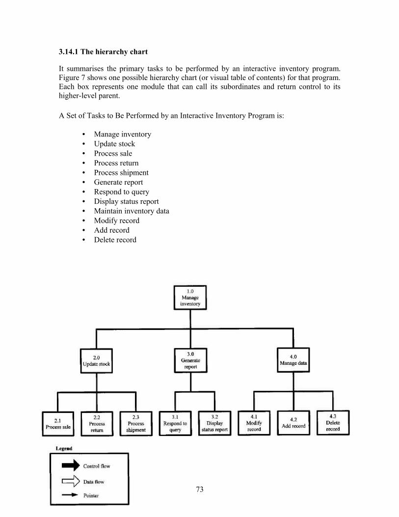
3.14.1 The hierarchy chart
It summarises the primary tasks to be performed by an interactive inventory program. Figure 7 shows one possible hierarchy chart (or visual table of contents) for that program. Each box represents one module that can call its subordinates and return control to its higher-level parent.
A Set of Tasks to Be Performed by an Interactive Inventory Program is:
• Manage inventory • Update stock • Process sale • Process return • Process shipment • Generate report • Respond to query • Display status report • Maintain inventory data • Modify record • Add record • Delete record
73

Figure 7 A hierarchy chart for an interactive inventory control program.
Source: www.hit.ac.il/staff/leonidM/information-systems/ch64.html
At the top of Figure 7 is the main control module, Manage inventory (module 1.0). It accepts a transaction, determines the transaction type, and calls one of its three subordinates (modules 2.0, 3.0, and 4.0).
Lower-level modules are identified relative to their parent modules; for example, modules 2.1, 2.2, and 2.3 are subordinates of module 2.0, modules 2.1.1, 2.1.2, and 2.1.3 are subordinates of 2.1, and so on. The module names consist of an active verb followed by a subject that suggests the module’s function.
The objective of the module identifiers is to uniquely identify each module and to indicate its place in the hierarchy. Some designers use Roman numerals (level I, level II) or letters (level A, level B) to designate levels. Others prefer a hierarchical numbering scheme; e.g., 1.0 for the first level; 1.1, 1.2, 1.3 for the second level; and so on. The key is consistency.
The box at the lower-left of Figure 7 is a legend that explains how the arrows on the hierarchy chart and the IPO charts are to be interpreted. By default, a wide clear arrow represents a data flow, a wide black arrow represents a control flow, and a narrow arrow indicates a pointer.
3.14.2 The IPO charts
An IPO chart is prepared to document each of the modules on the hierarchy chart.
74
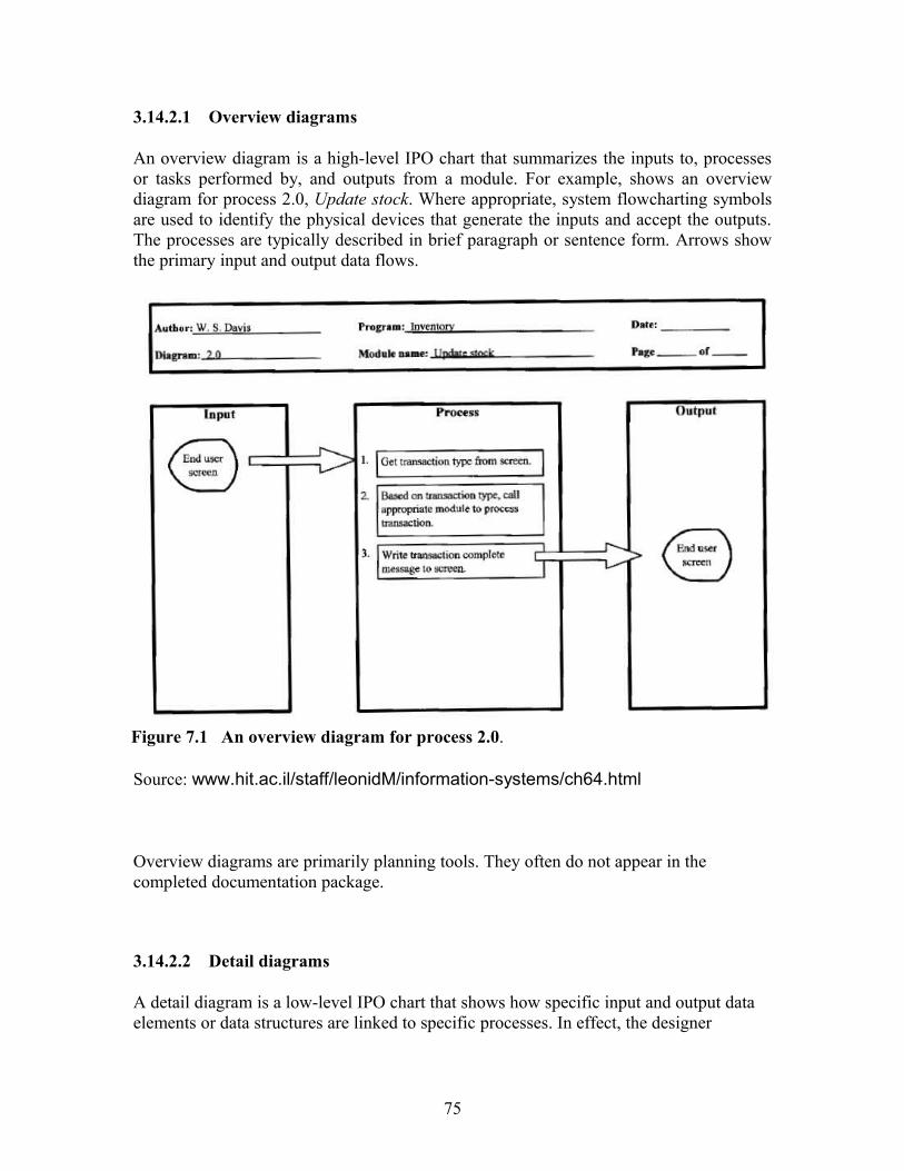
3.14.2.1 Overview diagrams
An overview diagram is a high-level IPO chart that summarizes the inputs to, processes or tasks performed by, and outputs from a module. For example, shows an overview diagram for process 2.0, Update stock. Where appropriate, system flowcharting symbols are used to identify the physical devices that generate the inputs and accept the outputs. The processes are typically described in brief paragraph or sentence form. Arrows show the primary input and output data flows.
Figure 7.1 An overview diagram for process 2.0.
Source: www.hit.ac.il/staff/leonidM/information-systems/ch64.html
Overview diagrams are primarily planning tools. They often do not appear in the completed documentation package.
3.14.2.2 Detail diagrams
A detail diagram is a low-level IPO chart that shows how specific input and output data elements or data structures are linked to specific processes. In effect, the designer
75

integrates a system flowchart into the overview diagram to show the flow of data and control through the module.
Figure 7.2 shows a detail diagram for module 2.0, Update stock. The process steps are written in pseudocode. Note that the first step writes a menu to the user screen and input data (the transaction type) flows from that screen to step 2. Step 3 is a case structure. Step 4 writes a transaction complete message to the user screen.
The solid black arrows at the top and bottom of the process box show that control flows from module 1.0 and, upon completion, returns to module 1.0. Within the case structure (step 3) are other solid black arrows.
Following case 0 is a return (to module 1.0). The two-headed black arrows following cases 1, 2, and 3 represent subroutine calls; the off-page connector symbols (the little home plates) identify each subroutine’s module number. Note that each subroutine is documented in a separate IPO chart. Following the default case, the arrow points to an on-page connector symbol numbered 1. Note the matching on-page connector symbol pointing to the select structure. On-page connectors are also used to avoid crossing arrows on data flows.
Figure 7.2 A detail diagram for process 2.1.
.
76

Source: www.hit.ac.il/staff/leonidM/information-systems/ch64.html
Often, detailed notes and explanations are written on an extended description that is attached to each detail diagram. The notes might specify access methods, data types, and so on.
Figure 64.4 shows a detail diagram for process 2.1. The module writes a template to the user screen, reads a stock number and a quantity from the screen, uses the stock number as a key to access an inventory file, and updates the stock on hand. Note that the logic repeats the data entry process if the stock number does not match an inventory record. A real IPO chart is likely to show the error response process in greater detail.
3.14.2.3 Simplified IPO charts
Some designers simplify the IPO charts by eliminating the arrows and system flowchart symbols and showing only the text. Often, the input and out put blocks are moved above the process block (Figure 64.5), yielding a form that fits better on a standard 8.5 × 11 (portrait orientation) sheet of paper. Some programmers insert modified IPO charts similar to Figure 64.5 directly into their source code as comments. Because the documentation is closely linked to the code, it is often more reliable than stand-alone HIPO documentation, and more likely to be maintained.
77
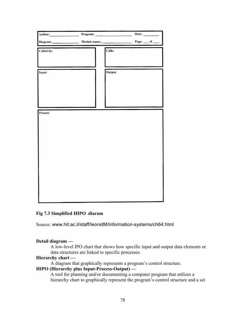
Fig 7.3 Simplified HIPO diaram
Source: www.hit.ac.il/staff/leonidM/information-systems/ch64.html
Detail diagram — A low-level IPO chart that shows how specific input and output data elements or data structures are linked to specific processes.
Hierarchy chart — A diagram that graphically represents a program’s control structure.
HIPO (Hierarchy plus Input-Process-Output) — A tool for planning and/or documenting a computer program that utilizes a hierarchy chart to graphically represent the program’s control structure and a set
78
of IPO (Input-Process-Output) charts to describe the inputs to, the outputs from, and the functions performed by each module on the hierarchy chart.
IPO (Input-Process-Output) chart — A chart that describes or documents the inputs to, the outputs from, and the functions (or processes) performed by a program module.
Overview diagram — A high-level IPO chart that summarizes the inputs to, processes or tasks performed by, and outputs from a module.
Visual Table of Contents (VTOC) — A more formal name for a hierarchy chart.
3.15 Software
In the 1970s and early 1980s, HIPO documentation was typically prepared by hand using a template. Some CASE products and charting programs include HIPO support. Some forms generation programs can be used to generate HIPO forms. The examples in this # were prepared using Visio.
Activity J Discuss the historical development of Case Tools
4.0 Conclusion
Programming tools are so important for effective program design.
5.0 Summary.
In this unit, you have learnt that:
• Programming environments gives the basic tools and Application Programming Interfaces, or APIs, necessary to construct programs.
• Using the HIPO technique, designers can evaluate and refine a program’s design, and correct flaws prior to implementation.
• CASE tools are a class of software that automates many of the activities involved in various life cycle phases
6.0 Tutor Marked Assignment
• Explain Programming Environment • What is Case Tools?, enumerate different categories of case tools• What is HIPO technique?• With the aid of well labeled diagrams, discuss the components of Hipo.
7.0 Further Reading And Other Resources
Gane, C. and Sarson, T., Structured Systems Analysis: Tools and Techniques, Prentice-Hall, Englewood Cliffs, NJ, 1979.
79

IBM Corporation, HIPO—A Design Aid and Documentation Technique, Publication Number GC20-1851, IBM Corporation, White Plains, NY, 1974. Katzan, H., Jr., Systems Design and Documentation: An Introduction to the HIPO Method, Van Nostrand Reinhold, New York, 1976.
Peters, L. J., Software Design: Methods and Techniques, Yourdon Press, New York, 1981.
Yourdon, E. and Constantine, Structured Design, Prentice-Hall, Englewood Cliffs, NJ, 1979.
Module 3 Implementation and Testing
Unit 1 Implementation
1.0 Introduction
This unit examines the implementation phase of software development. After studying the unit you are expected to have achieved the following objectives listed below.
80

2.0 Objectives
By the end of this unit, you should be able to:• Define clearly software Implementation • Differentiate between the three types of errors• Explain the application of Six Sigma to Software Implementation Projects• Discuss the Major Tasks in Implementation• Explain the Major Requirement in Implementation• Explain the Implementation Support
3.0 What is Implementation?
Code is formed from the deliverables of the design phase during implementation. It is the longest phase of the software development life cycle. Since code is produce here, the developer regards this phase as the main focus of the life cycle. Implementation my overlap with both the design and testing phases. As we learnt in previous unit many tools exists (CASE tools) to actually automate the production of code using information gathered and produced during the design phase. The implementation phase concerns with issues of quality, performance, baselines, libraries, and debugging. The end deliverable is the product itself.
3.1 The Implementation Phase
Source: Ronald LeRoi Burback 1998-12-14
. 3.2 Critical Error Removal
There are three kinds of errors in a system, namely critical errors, non-critical errors, and unknown errors.
3.2.1 A critical error prevents the system from fully satisfying its usage. The errors have to be corrected before the system can be given to a customer or even before future development can progress.
Phase Deliverable
Implementation Code
Critical Error Removal Table 1 The Implementation Phase
81

3.2.2 A non-critical error is known but the occurrence of the error does not notably affect the system's expected quality. There may indeed be many known errors in the system. They are usually listed in the release notes and have well established work arounds.
Actually, the system is likely to have many, yet-to-be-discovered errors. The outcome of these errors is unknown. Some may become critical while some may be simply fixed by patches or fixed in the next release of the system.
3.3 Application of Six Sigma to Software Implementation Projects Software implementation can be a demanding project. When a company is attempting new software integration, it can be hectic Six Sigma is a management approach meant to discover and control defects. A summary of Six Sigma can be found in Natasha Baker’s “Key Concepts of Six Sigma.” The technique consists of five steps:
• · Define• · Measure• · Analyze• · Improve• · Control
Defining the Implementation
By defining the goals, projects, and deliverables your company will have greater direction during the changeover. The goals and projects must be measurable. The following questions, for examples, may be necessary: Is it your goal to have 25% of your staff comfortable enough to train the remaining staff? Do you want full implementation of the software by March? By utilizing Six Sigma metrics careful monitoring of team productivity and implementation success is possible.
2. Measurement of the Implementation
Goals and projects must be usable with metrics. By using Six Sigma measurement methods, it is possible to follow user understanding, familiarity, and progress accurately. It should be noted that, continuous data is more useful than discrete data. This is because it gives a better implementation success rate overview.
3. Implementation Analysis
Analysis is important to tackle defects occurrence. The Six Sigma method examines essential relationships and ensures all factors are considered. For example, in a software implementation trial, employees are frustrated and confused by new processes. Careful analysis will look at the reasons behind the confusion.
4. Implementation Improvement
82

After analysis, it is important to look at how the implementation could improve. In the example utilizing the team members, perhaps utilizing proficient resources to mentor struggling resources will help. Six Sigma improvements depends upon experimental design and carefully constructed analysis of data in order to keep further defects in the implementation process at bay.
5. Control of the Implementation
If implementation is going to be successful, control is important. It involves consistent monitoring for proficiency. This ensures that the implementation does not fail. Any deviations from the goals set demand correcting before they become defects. For example, if you notice your team does not adapt quickly enough, you need to identify the causes before the deadline. By carefully monitoring the implementation process this way, will minimise the defect. The two most important features of software implementation using Six Sigma are setting measurable goals and employing metrics in order to maximize improvement and minimize the chance of defects in the new process.
3.4 Major Tasks in ImplementationThis part provides a brief description of each major task needed for the implementation of the system. The tasks described here are not particular to site but overall project tasks that are needed to install hardware and software, prepare data, and verify the system. Include the following information for the description of each major task, if appropriate:Add as many subsections as necessary to this section to describe all the major tasks adequately. The tasks described in this section are not site-specific, but generic or overall project tasks that are required to install hardware and software, prepare data, and verify the system.
Examples of major tasks are the following:• Providing overall planning and coordination for the implementation• Providing appropriate training for personnel• Ensuring that all manuals applicable to the implementation effort are
available when needed• Providing all needed technical assistance• Scheduling any special computer processing required for the
implementation• Performing site surveys before implementation• Ensuring that all prerequisites have been fulfilled before the
implementation date• Providing personnel for the implementation team• Acquiring special hardware or software• Performing data conversion before loading data into the system• Preparing site facilities for implementation
83

3.5 Major Requirement in Implementation
3.5.1 SecurityIf suitable for the system to be implemented, there is need to include an overview of the system security features and requirements during the implementation.
3.5.1.1 System Security FeaturesIt is pertinent to discuss the security features that will be associated with the system when it is implemented. It should include the primary security features associated with the system hardware and software. Security and protection of sensitive bureau data and information should be discussed.
3.5.1.2 Security during ImplementationThis part addresses security issues particularly related to the implementation effort. It will be necessary to consider for example, if LAN servers or workstations will he installed at a site with sensitive data preloaded on non-removable hard disk drives. It will also be important to see to how security would be provided for the data on these devices during shipping, transport, and installation so as not to allow theft of the devices to compromise the sensitive data.
3.6 Implementation SupportThis part describes the support such as: software, materials, equipment, and facilities necessary for the implementation, as well as the personnel requirements and training essential for the implementation.
3.6.1 Hardware, Software, Facilities, and MaterialsThis section, provides a list of support software, materials, equipment, and facilities required for the implementation..
3.6.1.1 HardwareThis section offers a list of support equipment and includes all hardware used for testing time implementation. For example, if a client/server database is implemented on a LAN, a network monitor or “sniffer” might be used, along with test programs. to determine the performance of the database and LAN at high-utilization rates
3.6.1.2 SoftwareThis section provides a list of software and databases required to support the implementation. Identify the software by name, code, or acronym. Identify which software is commercial off-the-shelf and which is State-specific. Identify any software used to facilitate the implementation process.
84

3.6.1.3 FacilitiesThis section identifies the physical facilities and accommodations required during implementation. Examples include physical workspace for assembling and testing hardware components, desk space for software installers, and classroom space for training the implementation stall. Specify the hours per day needed, number of days, and anticipated dates.
3.6.1.4 MaterialThis section provides a list of required support materials, such as magnetic tapes and disk packs.
3.7 PersonnelThis section describes personnel requirements and any known or proposed staffing requirements. It also describes the training, to be provided for the implementation staff.
3.7.1 Personnel Requirements and StaffingThis section, describes the number of personnel, length of time needed, types of skills, and skill levels for the staff required during the implementation period. If particular staff members have been selected or proposed for the implementation, identify them and their roles in the implementation.
3.7.2 Training of Implementation StaffThis section addresses the training, necessary to prepare staff for implementing and maintaining the system; it does not address user training, which is the subject of the Training Plan. It also describes the type and amount of training required for each of the following areas, if appropriate, for the system:
• System hardware/software installation• System support• System maintenance and modification
Present a training curriculum listing the courses that will be provided, a course sequence and a proposed schedule. If appropriate, identify which courses particular types of staff should attend by job position description.
If training will be provided by one or more commercial vendors, identify them, the course name(s), and a brief description of the course content.
If the training will be provided by State staff, provide the course name(s) and an outline of the content of each course. Identify the resources, support materials, and proposed instructors required to teach the course(s).
85

3.8 Performance MonitoringThis section describes the performance monitoring tool and techniques and how it will be used to help decide if the implementation is successful.
3.9 Configuration Management InterfaceThis section describes the interactions required with the Configuration Management (CM) representative on CM-related issues, such as when software listings will be distributed, and how to confirm that libraries have been moved from the development to the production environment.
3.10 Implementation Requirements by SiteThis section describes specific implementation requirements and procedures. If these requirements and procedures differ by site, repeat these subsections for each site; if they are the same for each site, or if there is only one implementation site, use these subsections only once. The “X” in the subsection number should be replaced with a sequenced number beginning with I. Each subsection with the same value of “X” is associated with the same implementation site. If a complete set of subsections will be associated with each implementation site, then “X” is assigned a new value for each site.
3.10.1 Site Name or identification for Site XThis section provides the name of the specific site or sites to be discussed in the subsequent sections.
3.10.2 Site RequirementsThis section defines the requirements that must he met for the orderly implementation of the system and describes the hardware, software, and site-specific facilities requirements for this area.
Any site requirements that do not fall into the following three categories and were not described in Section 3, Implementation Support, may be described in this section, or other subsections may be added following Facilities Requirements below:
• Hardware Requirements - Describe the site-specific hardware requirements necessary to support the implementation (such as. LAN hardware for a client/server database designed to run on a LAN).
• Software Requirements - Describe any software required to implement the system (such as, software specifically designed for automating the installation process).
• Data Requirements - Describe specific data preparation requirements and data that must be available for the system implementation. An example would be the assignment of individual IDs associated with data preparation.
86

• Facilities Requirements - Describe the site-specific physical facilities and accommodations required during the system implementation period. Some examples of this type of information are provided in Section 3.
3.10.3 Site implementation DetailsThis section addresses the specifics of the implementation for this site. Include a description of the implementation team, schedule, procedures, and database and data updates. This section should also provide information on the following:
• Team--If an implementation team is required, describe its composition and the tasks to be performed at this site by each team member.
• Schedule--Provide a schedule of activities, including planning and preparation, to be accomplished during implementation at this site. Describe the required tasks in chronological order with the beginning and end dates of each task. If appropriate, charts and graphics may be used to present the schedule.
• Procedures--Provide a sequence of detailed procedures required to accomplish the specific hardware and software implementation at this site. If necessary, other documents may be referenced. If appropriate, include a step-by-step sequence of the detailed procedures. A checklist of the installation events may he provided to record the results of the process.
If the site operations startup is an important factor in the implementation, then address startup procedures in some detail. If the system will replace an already operating system, then address the startup and cutover processes in detail. If there is a period of parallel operations with an existing system, address the startup procedures that include technical and operations support during the parallel cycle and the consistency of data within the databases of the two systems.
• Database--Describe the database environment where the software system and the database(s), if any, will be installed. Include a description of the different types of database and library environments (such as, production, test, and training databases).
• Include the host computer database operating procedures, database file and library naming conventions, database system generation parameters, and any other information needed to effectively establish the system database environment.
• Include database administration procedures for testing changes, if any, to the database management system before the system implementation.
87
• Data Update--If data update procedures are described in another document, such as the operations manual or conversion plan, that document may be referenced here. The following are examples of information to be included:
- Control inputs- Operating instructions- Database data sources and inputs- Output reports- Restart and recovery procedures
3.11 Back-Off PlanThis section specifies when to make the go/no go decision and the factors to be included in making the decision. The plan then goes on to provide a detailed list of steps and actions required to restore the site to the original, pre-conversion condition,
3.12 Post-Implementation VerificationThis section describes the process for reviewing the implementation and deciding if it was successful. It describes how an action item list will be created to rectify any noted discrepancies. It also references the Back-Off Plan for instructions on how to back-out the installation, if, as a result of the post-implementation verification, a no-go decision is made.
Activity K Explain the Major Requirement in Implementation
4.0 Conclusion
Implementation phase is vital aspect of software development. It is the longest phase of the software development life cycle. It is a phase where code is produced and as such tge developer regards it as the main focus of the software development life cycle.
5.0 SummaryIn this unit, you have learnt that:
• Code is formed from the deliverables of the design phase during implementation. • A critical error prevents the system from fully satisfying its usage. The errors
have to be corrected before the system can be given to a customer or even before future development can progress.
• A non-critical error is known but the occurrence of the error does not notably affect the system's expected quality.
• The system is likely to have many, yet-to-be-discovered errors known as unknown errors which may become critical while some may be simply fixed by patches or fixed in the next release of the system.
• The technique Six Sigma to Software Implementation Projects consists of five steps: Define, Measure, Analyze,· Improve, Control.
88

• The Major Tasks in Implementation include: Providing overall planning and coordination for the implementation, Providing appropriate training for personnelEnsuring that all manuals applicable to the implementation effort are available when needed, Providing all needed technical assistance, Scheduling any special computer processing required for the implementation, Performing site surveys before implementation, Ensuring that all prerequisites have been fulfilled before the implementation date, Providing personnel for the implementation team, Acquiring special hardware or software, Performing data conversion before loading data into the system, Preparing site facilities for implementation.
• Major Requirement in Implementation include: Security, Implementation Support, Personnel and Performance Monitoring
6.0 Tutor Marked Assignment
• What is software Implementation • Differentiate between critical, non-critical and unknown errors• Explain the application of Six Sigma Software Implementation techniques.• Discuss the Major Tasks in Implementation• Explain the various Implementation Support
7.0 Further Reading And Other Resources
Moshe Bar and Karl Franz Fogel. Open Source Development with CVS. The Coriolis Group, Scottsdale, AZ, 2001.
Kent Beck and Erich Gamma. Test infected: Programmers love writing tests. Java Report, 3(7):37–50, July 1998.
Stephen P. Berczuk and Brad Appleton. Software Configuration Management Patterns: Effective Teamwork, Practical Integration. Addison-Wesley, Boston, MA, 2002.
Don Bolinger, Tan Bronson, and Mike Loukides. Applying RCS and SCCS: From Source Control to Project Control. O'Reilly and Associates, Sebastopol, CA, 1995.
Unit 2 Testing Phase
1.0 Introduction
In the last unit, we looked at implementation phase of software development. In this unit, we shall consider the testing phase. It is important for stakeholders to have information
89

about the quality of product (software), hence the importance of testing cannot be overemphasised.
2.0 ObjectivesBy the end of this unit, you should be able to:
• Define clearly software testing• Explain testing methods.• Explain software testing process• Explain testing tools
3.0 Definition of software testing
Software testing is an empirical examination carried out to provide stakeholders with information about the quality of the product or service under test. Software Testing in addition provides an objective, independent view of the software to allow the business to value and comprehend the risks associated with implementation of the software.. Software Testing can also be viewed as the process of validating and verifying that a software program/application/product (1) meets the business and technical requirements that guided its design and development; (2) works as expected; and (3) can be implemented with the same characteristics. It is important to note that depending on the testing method used, software testing, can be applied at any time in the development process, though most of the test effort occurs after the requirements have been defined and the coding process has been completed.
Testing can never totally detect all the defects within software. Instead, it provides a comparison that put side by side the state and behavior of the product against the instrument someone applies to recognize a problem. These instruments may include specifications, contracts, comparable products, past versions of the same product, inferences about intended or expected purpose, user or customer expectations, relevant standards, applicable laws, or other criteria.
Every software product has a target audience. For instance, the audience for video game software is completely different from banking software. Software testing therefore, is the process of attempting to make this assessment whether the software product will be satisfactory to its end users, its target audience, its purchasers, and other stakeholders.
3.1 Brief History of software testing
In 1979, Glenford J. Myers introduced the separation of debugging from testing, illustrated the desire of the software engineering community to separate fundamental development activities, such as debugging, from that of verification. 1988, Dave Gelperin and William C. Hetzel classified the phases and goals in software testing in the following stages:
• Until 1956 - Debugging oriented. • 1957–1978 - Demonstration oriented.
90

• 1983–1987 - Evaluation oriented. • 1988–2000 - Prevention oriented.
3.2 Testing methods
Traditionally, software testing methods are divided into black box testing ,white box testing and Grey Box Testing. A test engineer used these approaches to describe his opinion when designing test cases.
3.2.1.1 Black box testing
Black box testing considers the software as a "black box" in the sense that there is no knowledge of internal implementation. Black box testing methods include: equivalence partitioning, boundary value analysis, all-pairs testing, fuzz testing, model-based testing, traceability matrix, exploratory testing and specification-based testing.
3.2.1.1 Specification-based testing: Specification-based testing intends to test the functionality of software based on the applicable requirements. Consequently, the tester inputs data into, and only sees the output from, the test object. This level of testing usually needs thorough test cases to be supplied to the tester, who can then verify that for a given input, the output value ,either "is" or "is not" the same as the expected value specified in the test case. Specification-based testing though necessary, but it is insufficient to guard against certain risks. Merits and Demerits: The black box testing has the advantage of "an unaffiliated opinion in the sense that there is no "bonds" with the code and the perception of the tester is very simple. He believes a code must have bugs and he goes for it. But, on the other hand, black box testing has the disadvantage of blind exploring because the tester doesn't know how the software being tested was actually constructed. As a result, there are situations when (1) a tester writes many test cases to check something that could have been tested by only one test case, and/or (2) some parts of the back-end are not tested at all.
3.2.1.2 White box testing
In a White box testing the tester has the privilege to the internal data structures and algorithms including the code that implement these.
Types of white box testing White box testing is of different types namely:
• API testing (application programming interface) - Testing of the application using Public and Private APIs
91

• Code coverage - creating tests to satisfy some criteria of code coverage (e.g., the test designer can create tests to cause all statements in the program to be executed at least once)
• Fault injection methods • Mutation testing methods • Static testing - White box testing includes all static testing
3.2.1.3 Grey Box Testing
Grey box testing requires gaining access to internal data structures and algorithms for purposes of designing the test cases, but testing at the user, or black-box level. Manipulating input data and formatting output cannot be regarded as grey box, because the input and output are clearly outside of the "black-box" that we are calling the system under test. This difference is important especially when conducting integration testing between two modules of code written by two different developers, where only the interfaces are exposed for test. However, changing a data repository can be seen as grey box, because the use would not ordinarily be able to change the data outside of the system under test. Grey box testing may also include reverse engineering to ascertain boundary values or error messages.
3.2.2 Integration Testing
Integration testing is any type of software testing that seeks to reveal clash of individual software modules to each other. Such integration flaws can result, when the new modules are developed in separate branches, and then integrated into the main project.
3.2.3 Regression Testing
Regression testing is any type of software testing that attempts to reveal software regressions. Regression of the nature can occurs at any time software functionality, that was previously working correctly, stops working as anticipated. Usually, regressions occur as an unplanned result of program changes, when the newly developed part of the software collides with the previously existing. Methods of regression testing include re-running previously run tests and finding out whether previously repaired faults have re- appeared. The extent of testing depends on the phase in the release process and the risk of the added features.
3.2.4 Acceptance testing
One of two things below can be regarded as Acceptance testing:
1. A smoke test which is used as an acceptance test prior to introducing a new build to the main testing process, i.e. before integration or regression.
2. Acceptance testing performed by the customer, usually in their lab environment on their own HW, is known as user acceptance testing (UAT).
92

3.2.5 Non Functional Software Testing
The following methods are used to test non-functional aspects of software:
• Performance testing confirms to see if the software can deal with large quantities of data or users. This is generally referred to as software scalability. This activity of Non Functional Software Testing is often referred to as Endurance Testing.
• Stability testing checks to see if the software can continuously function well in or above an acceptable period. This activity of Non Functional Software Testing is oftentimes referred to as load (or endurance) testing.
• Usability testing is used to check if the user interface is easy to use and understand.
• Security testing is essential for software that processes confidential data to prevent system intrusion by hackers.
• Internationalization and localization is needed to test these aspects of software, for which a pseudo localization method can be used.
Compare to functional testing, which establishes the correct operation of the software in that it matches the expected behavior defined in the design requirements, non-functional testing confirms that the software functions properly even when it receives invalid or unexpected inputs. Non-functional testing, especially for software, is meant to establish whether the device under test can tolerate invalid or unexpected inputs, thereby establishing the robustness of input validation routines as well as error-handling routines. An example of non-functional testing is software fault injection, in the form of fuzzing.
3.2.6 Destructive testing
Destructive testing attempts to cause the software or a sub-system to fail, in order to test its robustness.
3.3 Testing process
Testing process can take two forms: Usually the testing can be performed by an independent group of testers after the functionality is developed before it is sent to the customer. Another practice is to start software testing at the same time the project starts and it continues until the project finishes. The first practice always results in the testing phase being used as project buffer to compensate for project delays, thereby compromising the time devoted to testing.
Testing can be done on the following levels:
• Unit testing tests the minimal software component, or module. Each unit (basic component) of the software is tested to verify that the detailed design for the unit has been correctly implemented. In an object-oriented environment, this is usually at the class level, and the minimal unit tests include the constructors and destructors.
93

• Integration testing exposes defects in the interfaces and interaction between integrated components (modules). Progressively larger groups of tested software components corresponding to elements of the architectural design are integrated and tested until the software works as a system.
• System testing tests a completely integrated system to verify that it meets its requirements.
• System integration testing verifies that a system is integrated to any external or third party systems defined in the system requirements.
Before shipping the final version of software, alpha and beta testing are often done additionally:
• Alpha testing is simulated or actual operational testing by potential users/customers or an independent test team at the developers' site. Alpha testing is often employed for off-the-shelf software as a form of internal acceptance testing, before the software goes to beta testing.
• Beta testing comes after alpha testing. Versions of the software, known as beta versions, are released to a limited audience outside of the programming team. The software is released to groups of people so that further testing can ensure the product has few faults or bugs. Sometimes, beta versions are made available to the open public to increase the feedback field to a maximal number of future users.
Finally, acceptance testing can be conducted by the end-user, customer, or client to validate whether or not to accept the product. Acceptance testing may be performed as part of the hand-off process between any two phases of development.
Benchmarks may be employed during regression testing to ensure that the performance of the newly modified software will be at least as acceptable as the earlier version or, in the case of code optimization, that some real improvement has been achieved.
3.4.2 Testing Tools
Program testing and fault detection can be aided significantly by testing tools and debuggers. Testing/debug tools include features such as:
• Program monitors, permitting full or partial monitoring of program code including:
o Instruction Set Simulator, permitting complete instruction level monitoring and trace facilities
o Program animation, permitting step-by-step execution and conditional breakpoint at source level or in machine code
o Code coverage reports
94

• Formatted dump or Symbolic debugging, tools allowing inspection of program variables on error or at chosen points
• Automated functional GUI testing tools are used to repeat system-level tests through the GUI
• Benchmarks, allowing run-time performance comparisons to be made • Performance analysis (or profiling tools) that can help to highlight hot spots and
resource usage
Activity l Discuss the various testing methods.
4.0 ConclusionIt has been made abundantly clear that software testing is so important in assessing whether the software product will be satisfactory to its end users, its target audience, its purchasers, and other stakeholders.
5.0 SummaryIn this unit, you have learnt that:
• Software testing is an empirical examination carried out to provide stakeholders with information about the quality of the product or service under test.
• Traditionally, software testing methods are divided into black box testing, white box testing and Grey Box Testing. A test engineer used these approaches to describe his opinion when designing test cases.
• Black box testing considers the software as a "black box" in the sense that there is no knowledge of internal implementation.
• In White box testing the tester has the privilege to the internal data structures and algorithms including the code that implement these.
• Grey box testing requires gaining access to internal data structures and algorithms for purposes of designing the test cases, but testing at the user, or black-box level.
• Manipulating input data and formatting output cannot be regarded as grey box, because the input and output are clearly outside of the "black-box" that we are calling the system under test.
• Testing process can take two forms: (1) usually the testing can be performed by an independent group of testers after the functionality is developed before it is sent to the customer. (2) Another practice is to start software testing at the same time the project starts and it continues until the project finishes. The first practice always results in the testing phase being used as project buffer to compensate for project delays, thereby compromising the time devoted to testing.
• Testing/debug tools include features such as:
o Program monitors, permitting full or partial monitoring of program code o Formatted dump or Symbolic debugging, tools allowing inspection of
program variables on error or at chosen points o Automated functional GUI testing tools are used to repeat system-level
tests through the GUI
95
o Benchmarks, allowing run-time performance comparisons to be made o Performance analysis (or profiling tools) that can help to highlight hot
spots and resource usage
6.0 Tutor-Marked Assignment
• What is software testing?• Explain software testing process• Explain testing tools
7.0 Further Reading And Other Resources
Exploratory Testing, Cem Kaner, Florida Institute of Technology, Quality Assurance Institute Worldwide Annual Software Testing Conference, Orlando, FL, November 2006
Software errors cost U.S. economy $59.5 billion annually, NIST report
Myers, Glenford J. (1979). The Art of Software Testing. John Wiley and Sons. ISBN 0-471-04328-1.
Dr. Dobb's journal of software tools for the professional programmer (M&T Pub) 12 (1-6): 116. 1987.
Gelperin, D.; B. Hetzel (1988). "The Growth of Software Testing". CACM 31 (6). ISSN 0001-0782. Laycock, G. T. (1993) (PostScript). The Theory and Practice of Specification Based Software Testing. Dept of Computer Science, Sheffield University, UK. http://www.mcs.le.ac.uk/people/gtl1/thesis.ps.gz. Retrieved 2008-02-13.
Unit 3 Software Quality Assurance (SQA)
1.0 Introduction
96

In the last unit, we looked at testing phase of software development. In this unit, we shall consider the Software Quality Assurance (SQA). There is need to ensure that the software development and control processes described in the project's Management Plan are correctly carried out and that the project's procedures and standards are followed hence the need for Software Quality Assurance cannot be underestimated.
2.0 ObjectivesBy the end of this unit, you should be able to:
• Define clearly Software Quality Assurance• Explain the concept of standards and procedures.• Discuss Software Quality Assurance Activities • Discuss SQA Relationships to Other Assurance Activities • Discuss Software Quality Assurance During the Software Acquisition Life Cycle.
3.0 Concepts and Definitions
Software Quality Assurance (SQA) is defined as a planned and systematic approach to the evaluation of the quality of and adherence to software product standards, processes, and procedures. SQA includes the process of assuring that standards and procedures are established and are followed throughout the software acquisition life cycle. Compliance with agreed-upon standards and procedures is evaluated through process monitoring, product evaluation, and audits. Software development and control processes should include quality assurance approval points, where an SQA evaluation of the product may be done in relation to the applicable standards.
3.1 Standards and Procedures
Establishing standards and procedures for software development is critical, since these provide the structure from which the software evolves. Standards are the established yardsticks to which the software products are compared. Procedures are the established criteria to which the development and control processes are compared.
Standards and procedures establish the prescribed methods for developing software; the SQA role is to ensure their existence and adequacy. Proper documentation of standards and procedures is necessary since the SQA activities of process monitoring, product evaluation and auditing rely upon clear definitions to measure project compliance.
3.1.1 Types of standards include:
• Documentation Standards specify form and content for planning, control, and product documentation and provide consistency throughout a project.
97
• Design Standards specify the form and content of the design product. They provide rules and methods for translating the software requirements into the software design and for representing it in the design documentation.
• Code Standards specify the language in which the code is to be written and define any restrictions on use of language features. They define legal language structures, style conventions, rules for data structures and interfaces, and internal code documentation.
Procedures are explicit steps to be followed in carrying out a process. All processes should have documented procedures. Examples of processes for which procedures are needed are configuration management, non-conformance reporting and corrective action, testing, and formal inspections.
If developed according to the NASA DID, the Management Plan describes the software development control processes, such as configuration management, for which there have to be procedures, and contains a list of the product standards.
Standards are to be documented according to the Standards and Guidelines DID in the Product Specification. The planning activities required to assure that both products and processes comply with designated standards and procedures are described in the QA portion of the Management Plan.
3.2 Software Quality Assurance Activities
Product evaluation and process monitoring are the SQA activities that assure the software development and control processes described in the project's Management Plan are correctly carried out and that the project's procedures and
standards are followed. Products are monitored for conformance to standards and processes are monitored for conformance to procedures. Audits are a key technique used to perform product evaluation and process monitoring. Review of the Management Plan should ensure that appropriate SQA approval points are built into these processes.
3.2.1 Product evaluation is an SQA activity that assures standards are being followed. Ideally, the first products monitored by SQA should be the project's standards and procedures. SQA assures that clear and achievable standards exist and then evaluates compliance of the software product to the established standards. Product evaluation assures that the software product reflects the requirements of the applicable standard(s) as identified in the Management Plan.
3.2.2 Process monitoring is an SQA activity that ensures that appropriate steps to carry out the process are being followed. SQA monitors processes by comparing the actual steps carried out with those in the documented procedures. The Assurance
98

section of the Management Plan specifies the methods to be used by the SQA process monitoring activity.
A fundamental SQA technique is the audit, which looks at a process and/or a product in depth, comparing them to established procedures and standards. Audits are used to
review management, technical, and assurance processes to provide an indication of the quality and status of the software product.
The purpose of an SQA audit is to assure that proper control procedures are being followed, that required documentation is maintained, and that the developer's status reports accurately reflect the status of the activity. The SQA product is an audit report to management consisting of findings and recommendations to bring the development into conformance with standards and/or procedures.
3.3. SQA Relationships to Other Assurance Activities
Some of the more important relationships of SQA to other management and assurance activities are described below.
3.3.1 Configuration Management Monitoring
SQA assures that software Configuration Management (CM) activities are performed in accordance with the CM plans, standards, and procedures. SQA reviews the CM plans for compliance with software CM policies and requirements and
provides follow-up for nonconformances. SQA audits the CM functions for adherence to standards and procedures and prepares reports of its findings.
The CM activities monitored and audited by SQA include baseline control, configuration identification, configuration control, configuration status accounting, and configuration authentication. SQA also monitors and audits the software library. SQA assures that:
• Baselines are established and consistently maintained for use in subsequent baseline development and control.
• Software configuration identification is consistent and accurate with respect to the numbering or naming of computer programs, software modules, software units, and associated software documents.
99

• Configuration control is maintained such that the software configuration used in critical phases of testing, acceptance, and delivery is compatible with the associated documentation.
• Configuration status accounting is performed accurately including the recording and reporting of data reflecting the software's configuration identification, proposed changes to the configuration identification, and the implementation status of approved changes.
• Software configuration authentication is established by a series of configuration reviews and audits that exhibit the performance required by the software requirements specification and the configuration of the software is accurately reflected in the software design documents.
• Software development libraries provide for proper handling of software code, documentation, media, and related data in their various forms and versions from the time of their initial approval or acceptance until they have been incorporated into the final media.
• Approved changes to baselined software are made properly and consistently in all products, and no unauthorized changes are made.
3.3.2 Verification and Validation Monitoring
SQA assures Verification and Validation (V&V) activities by monitoring technical reviews, inspections, and walkthroughs.The SQA role in formal testing is described in the next section. The SQA role in reviews,inspections, and walkthroughs is to observe, participate as needed, and verify that they were properly conducted and documented. SQA also ensures that any actions required are assigned, documented, scheduled, and updated.Formal software reviews should be conducted at the end of each phase of the life cycle to identify problems and determine whether the interim product meets all applicable requirements. Examples of formal reviews are the Preliminary Design Review (PDR), Critical Design Review (CDR), and Test Readiness Review (TRR). A review looks at the overall picture of the product being developed to see if it satisfies its requirements. Reviews are part of the development process, designed to provide a ready/not-ready decision to begin the next phase. In formal reviews, actual work done is compared with established standards. SQA's main objective in reviews is to assure that the Management and Development Plans have been followed, and that the product is ready to proceed with the next phase of development. Although the decision to proceed is a management decision, SQA is responsible for advising management and participating in the decision. An inspection or walkthrough is a detailed examination of a product on a step-by-step or line-of-code by line-of-code basis to find errors. For inspections and walkthroughs, SQA assures, at a minimum that the process is properly completed and that needed follow-up is done. The inspection process may be used to measure compliance to standards.
100

3.3.3 Formal Test Monitoring
SQA assures that formal software testing, such as Acceptance testing, is done in accordance with plans and procedures. SQA reviews testing documentation for completeness and adherence to standards. The documentation review includes test plans,test specifications, test procedures, and test reports. SQA monitors testing and provides follow-up on nonconformances. By test monitoring, SQA assures software completeness and readiness for delivery. The objectives of SQA in monitoring formal software testing are to assure that:
• The test procedures are testing the software requirements in accordance with test plans.
• The test procedures are verifiable.
• The correct or "advertised" version of the software is being tested (by SQA monitoring of the CM activity).
• The test procedures are followed.
• Nonconformances occurring during testing (that is, any incident not expected in the test procedures) are noted and recorded.
• Test reports are accurate and complete.
• Regression testing is conducted to assure nonconformances have been corrected.
• Resolution of all nonconformances takes place prior to delivery.
Software testing verifies that the software meets its requirements. The quality of testing is assured by verifying that project requirements are satisfied and that the testing process is in accordance with the test plans and procedures.
3.4 Software Quality Assurance during the Software Acquisition Life Cycle
In addition to the general activities described in subsections C and D, there are phase-specific SQA activities that should be conducted during the Software Acquisition
Life Cycle. At the conclusion of each phase, SQA concurrence is a key element in the management decision to initiate the following life cycle phase. Suggested activities for each phase are described below.
3.4.1 Software Concept and Initiation Phase
101

SQA should be involved in both writing and reviewing the Management Plan in order to assure that the processes, procedures, and standards identified in the plan are appropriate, clear, specific, and auditable. During this phase, SQA also provides the QA section of the Management Plan.
3.4.2 Software Requirements Phase
During the software requirements phase, SQA assures that software requirements are complete, testable, and properly expressed as functional, performance, and interface requirements.
3.4.3 Software Architectural (Preliminary) Design Phase
SQA activities during the architectural (preliminary) design phase include:
• Assuring adherence to approved design standards as designated in the Management Plan.
• Assuring all software requirements are allocated to software components.
• Assuring that a testing verification matrix exists and is kept up to date.
• Assuring the Interface Control Documents are in agreement with the standard in form and content.
• Reviewing PDR documentation and assuring that all action items are resolved.
• Assuring the approved design is placed under configuration management.
3.4.4 Software Detailed Design Phase
SQA activities during the detailed design phase include:
• Assuring that approved design standards are followed.
• Assuring that allocated modules are included in the detailed design.
• Assuring that results of design inspections are included in the design.
• Reviewing CDR documentation and assuring that all action items are resolved.
3.4.5 Software Implementation Phase
102

SQA activities during the implementation phase include the audit of:
• Results of coding and design activities including the
schedule contained in the Software Development Plan.
• Status of all deliverable items.
• Configuration management activities and the software development library.
• Nonconformance reporting and corrective action system.
3.4.6 Software Integration and Test Phase
SQA activities during the integration and test phase include:
• Assuring readiness for testing of all deliverable items.
• Assuring that all tests are run according to test plans and procedures and that any non-conformances are reported and resolved.
• Assuring that test reports are complete and correct.
• Certifying that testing is complete and software and documentation are ready for delivery.
• Participating in the Test Readiness Review and assuring all action items are completed.
3.4.7 Software Acceptance and Delivery Phase
As a minimum, SQA activities during the software acceptance and delivery phase include assuring the performance of a final configuration audit to demonstrate that all
deliverable items are ready for delivery.
3.4.8 Software Sustaining Engineering and Operations Phase
During this phase, there will be mini-development cycles to enhance or correct the software. During these development cycles, SQA conducts the appropriate phase-specific activities described above.
3.4.9 Techniques and Tools
SQA should evaluate its needs for assurance tools versus those available off-the-shelf for applicability to the specific project, and must develop the others it requires. Useful tools might include audit and inspection checklists and automatic code standards analyzers.
103

Activity J Discuss Software Quality Assurance during the Software Acquisition Life Cycle
4.0 Conclusion
There is the need to ensure Software quality and adherence to software product standards, processes, and procedures and this is what Software Quality Assurance is out to achieve.
5.0 Summary
In this unit, you have learnt that:
• Software Quality Assurance (SQA) is a planned and systematic approach to the evaluation of the quality of and adherence to software product standards, processes, and procedures.
• Standards are the established yardsticks to which the software products are compared. Procedures are the established criteria to which the development and control processes are compared.
• Product evaluation and process monitoring are the SQA activities that assure the software development and control processes described in the project's Management Plan are correctly carried out and that the project's procedures and
6.0 Tutor-Marked Assignment
What is Software Quality Assurance?Explain the concept of standards and procedures.Discuss Software Quality Assurance Activities
7.0 Further Reading And Other Resources
Pyzdek, T, "Quality Engineering Handbook", 2003, ISBN 0-8247-4614-7
Godfrey, A. B., "Juran's Quality Handbook", 1999, ISBN 0-07-034003-X
http://www.nrc.gov/reading-rm/doc-collections/cfr/part050/part050-appb.html
104

Unit 4 Compatibility
1.0 Introduction
In the last unit, we considered Software Quality Assurance (SQA). We saw the essence of Software Quality Assurance to ensure that the software development and control processes described in the project's Management Plan are correctly carried out and that the project's procedures and standards are followed at testing phase of software development. In this unit, we shall look at Compatibility testing. After studying the unit you are expected to have achieved the following objectives listed below.
2.0 ObjectivesBy the end of this unit, you should be able to:
• Define Compatibility Testing• Explain Usefulness of Compatibility Testing.
3.0 What is Compatibility Testing?Software testing comes in different types. Compatibility testing is one of the several types of software testing which can be carried out on a system that is develop based on certain yardsticks and which has to perform definite functionality in an already existing setup/environment. Many things are decided n compatibility of a system/application being developed with, for example, other systems/applications, OS, Network. They include the use of the system/application in that environment, demand of the system/application etc. On many occasions, the reason while users prefer not to go for an application/system cannot be unconnected with it non-compatibility of such application/system with any other system/application, network, hardware or OS they are already using. This explains the reason why the efforts of developers may appear to be in vain. Compatibility testing can also be used to certify compatibility of the system/application/website built with various other objects such as other web browsers, hardware platforms, users, operating systems etc. It helps to find out how well a system performs in a particular environment such as hardware, network; operating system etc. Compatibility testing can be performed manually or with automation tools.
3.1 Compatibility testing computing environment.
. Computing environment that will require compatibly testing may include some or all of the below mentioned elements:
• Computing capacity of Hardware Platform (IBM 360, HP 9000, etc.).. • Bandwidth handling capacity of networking hardware • Compatibility of peripherals (Printer, DVD drive, etc.) • Operating systems (MVS, UNIX, Windows, etc.) • Database (Oracle, Sybase, DB2, etc.) • Other System Software (Web server, networking/ messaging tool, etc.) • Browser compatibility (Firefox, Netscape, Internet Explorer, Safari, etc.)
105

Browser compatibility testing which can also be referred to as user experience testing requires that the web applications are tested on different web browsers, to ensure the following:
• Users have the same visual experience irrespective of the browsers through which they view the web application.
• In terms of functionality, the application must behave and respond the same way across different browsers.
Compatibility between versions: This has to do with testing of the performance of system/application in connection with its own predecessor/successor versions. This is sometimes referred to as backward and forward compatibility. For example, Windows 98 was developed with backward compatibility for Windows 95.
Software Compatibility testing: This is the evaluation of the performance of system/application in connection with other software. For example: Software compatibility with operating tools for network, web servers, messaging tools etc.
Operating System compatibility testing: This is the evaluation of the performance of system/application in connection with the underlying operating system on which it will be used.
Databases compatibility testing: Many applications/systems operate on databases. Database compatibility testing is used to evaluate an application/system’s performance in connection to the database it will interact with.
3.3 Usefulness of Compatibility Testing
Compatibility testing can help developers understand the yardsticks that their system/application needs to reach and fulfil, so as to get acceptance by intended users who are already using some OS, network, software and hardware etc. It also helps the users to find out which system will better fit in the existing setup they are using.
3.4 Certification testing falls within the range of Compatibility testing. Product Vendors do run the complete suite of testing on the newer computing environment to get their application certified for a specific Operating Systems or Databases.
Activity K What is Browser compatibility testing
4.0 Conclusion
Compatibility testing is highly beneficial to software development. It can help developers understand the criteria that their system/application needs to attain and fulfil, in order to get accepted by intended users who are already using some OS, network, software and hardware etc. It also helps the users to find out which system will better fit in the existing
106
setup they are using.
5.0 Summary
In this unit, we have learnt that:
• Compatibility testing is one of the several types of software testing performed on a system that is built based on certain criteria and which has to perform specific functionality in an already existing setup/environment.
• Compatibility testing can be automated using automation tools or can be performed manually and is a part of non-functional software testing.
• Computing environment may contain some or all of the below mentioned elements:
o Computing capacity of Hardware Platform (IBM 360, HP 9000, etc.).. o Bandwidth handling capacity of networking hardware o Compatibility of peripherals (Printer, DVD drive, etc.) o Operating systems (MVS, UNIX, Windows, etc.) o Database (Oracle, Sybase, DB2, etc.) o Other System Software (Web server, networking/ messaging tool, etc.) o Browser compatibility (Firefox, Netscape, Internet Explorer, Safari, etc.)
• The most important use of the compatibility testing is to ensure its performance in a computing environment in which it is supposed to operate. This helps in figuring out necessary changes/modifications/additions required to make the system/application compatible with the computing environment.
6.0 Tutor-Marked Assignment• Define Compatibility Testing• Explain Usefulness of Compatibility Testing.• What are the elements in computing enviroment?
7.0 Further Reading And Other Resources
E. Anderson , Z. Bai , J. Dongarra , A. Greenbaum , A. McKenney , J. Du Croz , S. Hammerling , J. Demmel , C. Bischof , D. Sorensen, LAPACK: a portable linear algebra library for high-performance computers, Proceedings of the 1990 conference on Supercomputing, p.2-11, October 1990, New York, New York, United States
S. Balay, K. Buschelman, V. Eijkhout, W. D. Gropp, D. Kaushik, M. G. Knepley, L. C. McInnes, B. F. Smith, and H. Zhang. PETSc users manual. Technical Report ANL-95/11 -- Revision 2.3.2, Argonne National Laboratory, Sep. 2006.
107

Myra B. Cohen , Matthew B. Dwyer , Jiangfan Shi, Coverage and adequacy in software product line testing, Proceedings of the ISSTA 2006 workshop on Role of software architecture for testing and analysis, p.53-63, July 17-20, 2006, Portland, Maine [doi>10.1145/1147249.1147257]
Uni 5 Software verification and validation
108
1.0 Introduction
In the last unit, we considered Compatibility testing .You will recall that, Compatibility testing is highly beneficial to software development. It can help developers understand the criteria that their system/application needs to attain and fulfil, in order to get accepted by intended users who are already using some OS, network, software and hardware etc. It also helps the users to find out which system will better fit in the existing setup they are using. In this unit we are going to look at software verification and validation.After studying the unit you are expected to have achieved the following objectives listed below.
2.0 ObjectivesBy the end of this unit, you should be able to:
• Define software verification and validation• Outline the method of verification and validation• Discuss Software Verification & Validation Model• Discuss terms used in validation process
3.0 What is Verification and Validation (V&V)
Verification and Validation (V&V) is the process of checking that a software system meets specifications and that it fulfils its expected purpose. It is normally part of the software testing process of a project.
According to the Capability Maturity Model (CMMI-SW v1.1),
• Verification is the process of evaluating software to determine whether the products of a given development phase satisfy the conditions imposed at the start of that phase. [IEEE-STD-610].
• Validation is the process of evaluating software during or at the end of the development process to determine whether it satisfies specified requirements. [IEEE-STD-610]
In other words, validation ensures that the product actually meets the user's needs, and that the specifications were correct in the first place, while verification is ensuring that the product has been built according to the requirements and design specifications. Validation ensures that ‘you built the right thing’. Verification ensures that ‘you built it right’. Validation confirms that the product, as provided, will fulfill its intended use.
Looking at it from arena of modeling and simulation, the definitions of validation, verification and accreditation are similar:
• Validation is the process of determining the degree to which a model, simulation, or federation of models and simulations, and their associated data are accurate representations of the real world from the perspective of the intended use(s).
109

Accreditation is the formal certification that a model or simulation is acceptable to be used for a specific purpose.
• Verification is the process of determining that a computer model, simulation, or federation of models and simulations implementations and their associated data accurately represents the developer's conceptual description and specifications.
3.1 Classification of methods
In mission-critical systems where flawless performance is absolutely necessary, formal methods can be used to ensure the correct operation of a system. However, often for non-mission-critical systems, formal methods prove to be very costly and an alternative method of V&V must be sought out. In this case, syntactic methods are often used.
3.2 Test cases
A test case is a tool used in the Verification and Validation process.
The Quality Assurance (QA) team prepares test cases for verification and these help to determine if the process that was followed to develop the final product is right.
The Quality Certificate (QC) team uses a test case for validation and this will ascertain if the product is built according to the requirements of the user. Other methods, such as reviews, provide for validation in Software Development Life Cycle provided it is used early for validation.
3.3 Independent Verification and Validation
Verification and validation often is carried out by a separate group from the development team; in this case, the process is called "Independent Verification and Validation", or IV&V.
3.4 Regulatory environment
The task is must to meet the compliance requirements of law regulated industries, which is often guided by government agencies or industrial administrative authorities. FDA even demands to validate software versions and patches.
3.5 Software Verification & Validation Model
‘Verification & Validation Model’ is used in improvement of software project development life cycle.
110

Fig 8 Verification and Validation Model
Source: http://www.buzzle.com/editorials/4-5-2005-68117.asp
A perfect software product is developed when every step is taken in right direction. That is to say that “A right product is developed in a right manner”. Software Verification Model helps to achieve this and also help to improve the quality of the software product.
The model will not only will not only makes sure that certain rules are followed at the time of development of a software but will also ensure that the product that is developed fulfils the required specifications. The result is that risk associated with any software project up to certain level is reduced by helping in detection and correction of errors and mistakes, which are unknowingly done during the development process. 3.6 Few terms involved in Verification:
3.61. Inspection: Inspection involves a team of few people usually about 3-6 people. It usually led by a leader, which properly reviews the documents and work product during various phases of the product development life cycle. The product, as well as related documents is presented to the team, the members of which carry different interpretations of the presentation. The bugs that are discovered during the inspection are conveyed to the next level in order to take care of them.
3.6.2 Walkthroughs:
111

In walkthrough inspection is carried out without formal preparation (of any presentation or documentations). During the walkthrough, the presenter/author introduces the material to all the participants in order to make them familiar with it. Though walkthroughs can help in finding bugs, they are used for knowledge sharing or communication purpose.
3.6.3 Buddy Checks: Buddy Checks does not involve a team rather, one person goes through the documents prepared by another person in order. to find out bugs which the author couldn’t find previously.
The activities involved in Verification process are: Requirement Specification verification, Functional design verification, internal/system design verification and code verification Each activity ascertains that the product is developed correctly and every requirement, every specification, design code etc. is verified.
3.7 Terms used in Validation process:
3.7.1 Code Validation/Testing: Unit Code Validation or Unit Testing is a type of testing, which the developers conduct in order to find out any bug in the code unit/module developed by them. Code testing other than Unit Testing can be done by testers or developers.
3.7.2 Integration Validation/Testing: Integration testing is conducted in order to find out if different (two or more) units/modules match properly. This test helps in finding out if there is any defect in the interface between different modules.
3.7.3 Functional Validation/Testing: This type of testing is meant to find out if the system meets the functional requirements. In this type of testing, the system is validated for its functional behavior. Functional testing does not deal with internal coding of the project, in stead, it checks if the system behaves as per the expectations.
3.7.4 User Acceptance Testing or System Validation: In this type of testing, the developed product is handed over to the user/paid testers in order to test it in real time state. The product is validated to find out if it works according to the system specifications and satisfies all the user requirements. As the user/paid testers use the software, it may happen that bugs that are yet undiscovered, come up, which are communicated to the developers to be fixed. This helps in improvement of the final product.
Activity L Discuss Software Verification & Validation Model
112

4.0 Conclusion
The importance of Verification and Validation cannot be overemphasisd. Verification and Validation (V&V) checks that a software system meets specifications and that it fulfils its intended purpose.
5.0 Summary
In this unit, we have learnt that:
• Verification and Validation (V&V) is the process of checking that a software system meets specifications and that it fulfils its intended purpose.
• In mission-critical systems where flawless performance is absolutely necessary, formal methods can be used to ensure the correct operation of a system. However, often for non-mission-critical systems, formal methods prove to be very costly and an alternative method of V&V must be sought out. In this case, syntactic methods are often used.
• Verification and validation often is carried out by a separate group from the development team; in this case, the process is called "Independent Verification and Validation
6.0 Tutor-Marked Assignment
• Define software verification and validation• Outline the method of verification and validation • Discuss terms used in validation process
7.0 Further Reading And Other Resources
Department of Defense Documentation of Verification, Validation & Accreditation (VV&A) for Models and Simulations, Missile Defense Agency, 2008
General Principles of Software validation; Final Guidance for Industry and FDA Staff" (PDF). Food and Drug Administration. 11 January 2002. http://www.fda.gov/downloads/MedicalDevices/DeviceRegulationandGuidance/GuidanceDocuments/ucm085371.pdf. Retrieved 12 July 2009.
Guidance for Industry: Part 11, Electronic Records; Electronic Signatures — Scope and Application" (PDF). Food and Drug Administration. August 2003. http://www.fda.gov/downloads/Drugs/GuidanceComplianceRegulatoryInformation/Guidances/UCM072322.pdf. Retrieved 12 July 2009.
113