Schneider Electric Harmony control stations and enclosures · Harmony™ control stations and...
30
Harmony ™ control stations and enclosures Catalog 2011 Courtesy of Steven Engineering, Inc. - (800) 258-9200 - [email protected] - www.stevenengineering.com
Transcript of Schneider Electric Harmony control stations and enclosures · Harmony™ control stations and...
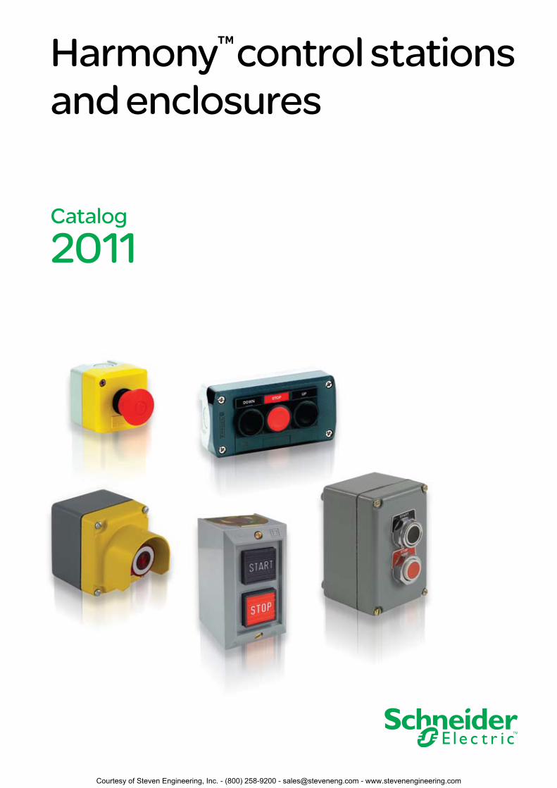
Harmony™ control stations and enclosures
Catalog
2011
Courtesy of Steven Engineering, Inc. - (800) 258-9200 - [email protected] - www.stevenengineering.com

Courtesy of Steven Engineering, Inc. - (800) 258-9200 - [email protected] - www.stevenengineering.com
3
Contents Harmony™ control stations and enclosures
Selection guide . . . . . . . . . . . . . . . . . . . . . . . . . . . . . . . . . . . . . . 4
Introduction . . . . . . . . . . . . . . . . . . . . . . . . . . . . . . . . . . . . . . . . . 6
XAL 22 mm control stations:
Components . . . . . . . . . . . . . . . . . . . . . . . . . . . . . . . . . . . . . . . . . 7
Specifications . . . . . . . . . . . . . . . . . . . . . . . . . . . . . . . . . . . . . . . 8
References . . . . . . . . . . . . . . . . . . . . . . . . . . . . . . . . . . . . . . . . . 10
Dimensions . . . . . . . . . . . . . . . . . . . . . . . . . . . . . . . . . . . . . . . . 12
XAP 22 mm enclosures:
Components . . . . . . . . . . . . . . . . . . . . . . . . . . . . . . . . . . . . . . . . 14
Specifications . . . . . . . . . . . . . . . . . . . . . . . . . . . . . . . . . . . . . . 15
References . . . . . . . . . . . . . . . . . . . . . . . . . . . . . . . . . . . . . . . . . 16
Dimensions . . . . . . . . . . . . . . . . . . . . . . . . . . . . . . . . . . . . . . . . 16
9001B standard duty control stations:
References . . . . . . . . . . . . . . . . . . . . . . . . . . . . . . . . . . . . . . . . . 20
Dimensions . . . . . . . . . . . . . . . . . . . . . . . . . . . . . . . . . . . . . . . . 22
9001KY/SKY 30 mm control stations:
Components . . . . . . . . . . . . . . . . . . . . . . . . . . . . . . . . . . . . . . . . 24
References . . . . . . . . . . . . . . . . . . . . . . . . . . . . . . . . . . . . . . . . . 25
Dimensions . . . . . . . . . . . . . . . . . . . . . . . . . . . . . . . . . . . . . . . . 27
Index . . . . . . . . . . . . . . . . . . . . . . . . . . . . . . . . . . . . . . . . . . . . . . 28
Courtesy of Steven Engineering, Inc. - (800) 258-9200 - [email protected] - www.stevenengineering.com
1
2
3
4
5
6
7
8
9
10
4
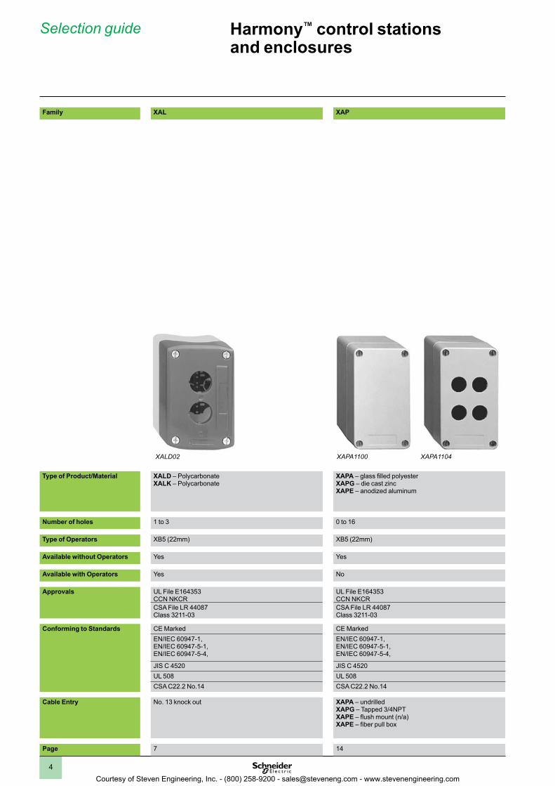
Family XAL XAP
Type of Product/Material XALD – PolycarbonateXALK – Polycarbonate
XAPA – glass filled polyesterXAPG – die cast zincXAPE – anodized aluminum
Number of holes 1 to 3 0 to 16
Type of Operators XB5 (22mm) XB5 (22mm)
Available without Operators Yes Yes
Available with Operators Yes No
Approvals UL File E164353 CCN NKCR
UL File E164353 CCN NKCR
CSA File LR 44087 Class 3211-03
CSA File LR 44087 Class 3211-03
Conforming to Standards CE Marked CE MarkedEN/IEC 60947-1,EN/IEC 60947-5-1, EN/IEC 60947-5-4,
EN/IEC 60947-1,EN/IEC 60947-5-1, EN/IEC 60947-5-4,
JIS C 4520 JIS C 4520UL 508 UL 508CSA C22.2 No.14 CSA C22.2 No.14
Cable Entry No. 13 knock out XAPA – undrilledXAPG – Tapped 3/4NPTXAPE – flush mount (n/a) XAPE – fiber pull box
Page 7 14
Harmony™ control stations and enclosures
Selection guide
XALD02 XAPA1104XAPA1100
Courtesy of Steven Engineering, Inc. - (800) 258-9200 - [email protected] - www.stevenengineering.com
1
2
3
4
5
6
7
8
9
10
5
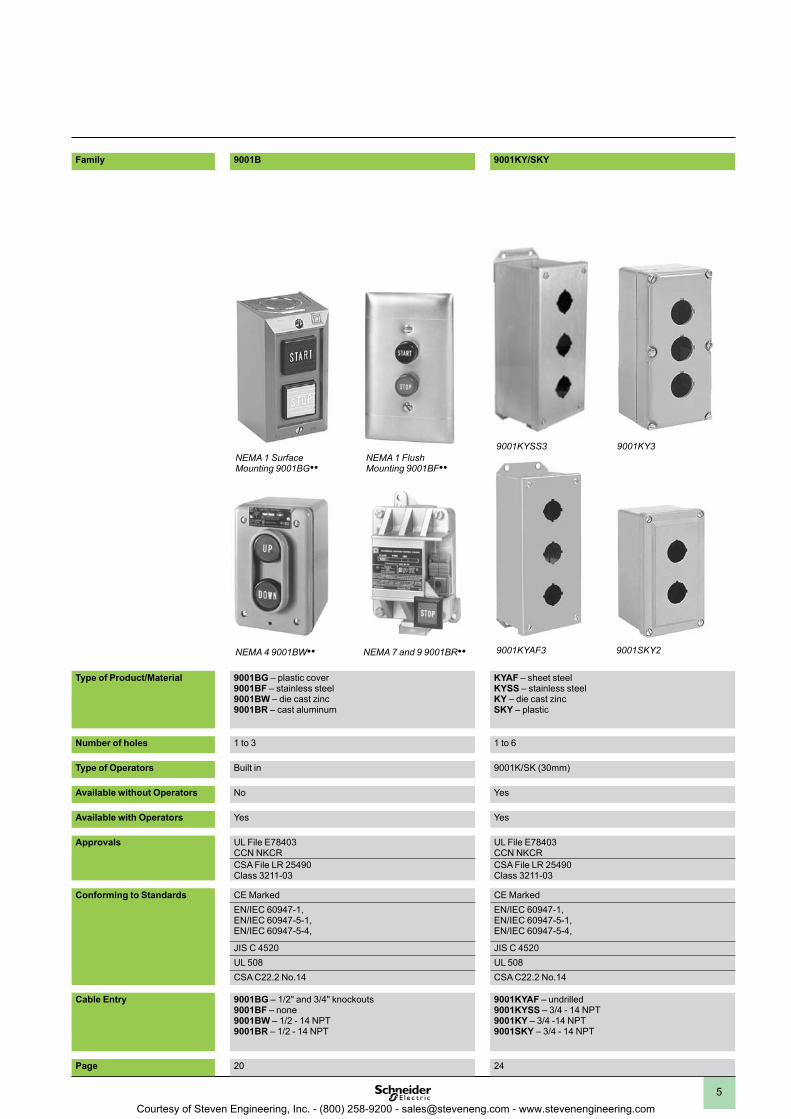
Family 9001B 9001KY/SKY
Type of Product/Material 9001BG – plastic cover9001BF – stainless steel9001BW – die cast zinc9001BR – cast aluminum
KYAF – sheet steelKYSS – stainless steelKY – die cast zincSKY – plastic
Number of holes 1 to 3 1 to 6
Type of Operators Built in 9001K/SK (30mm)
Available without Operators No Yes
Available with Operators Yes Yes
Approvals UL File E78403 CCN NKCR
UL File E78403 CCN NKCR
CSA File LR 25490 Class 3211-03
CSA File LR 25490 Class 3211-03
Conforming to Standards CE Marked CE MarkedEN/IEC 60947-1,EN/IEC 60947-5-1, EN/IEC 60947-5-4,
EN/IEC 60947-1,EN/IEC 60947-5-1, EN/IEC 60947-5-4,
JIS C 4520 JIS C 4520UL 508 UL 508CSA C22.2 No.14 CSA C22.2 No.14
Cable Entry 9001BG – 1/2" and 3/4" knockouts9001BF – none9001BW – 1/2 - 14 NPT9001BR – 1/2 - 14 NPT
9001KYAF – undrilled9001KYSS – 3/4 - 14 NPT9001KY – 3/4 -14 NPT9001SKY – 3/4 - 14 NPT
Page 20 24
NEMA 1 Surface Mounting 9001BG••
NEMA 1 Flush Mounting 9001BF••
NEMA 4 9001BW•• NEMA 7 and 9 9001BR••
9001KYSS3
9001SKY29001KYAF3
9001KY3
Courtesy of Steven Engineering, Inc. - (800) 258-9200 - [email protected] - www.stevenengineering.com
1
2
3
4
5
6
7
8
9
10
6
Harmony™ control stations and enclosures
Introduction
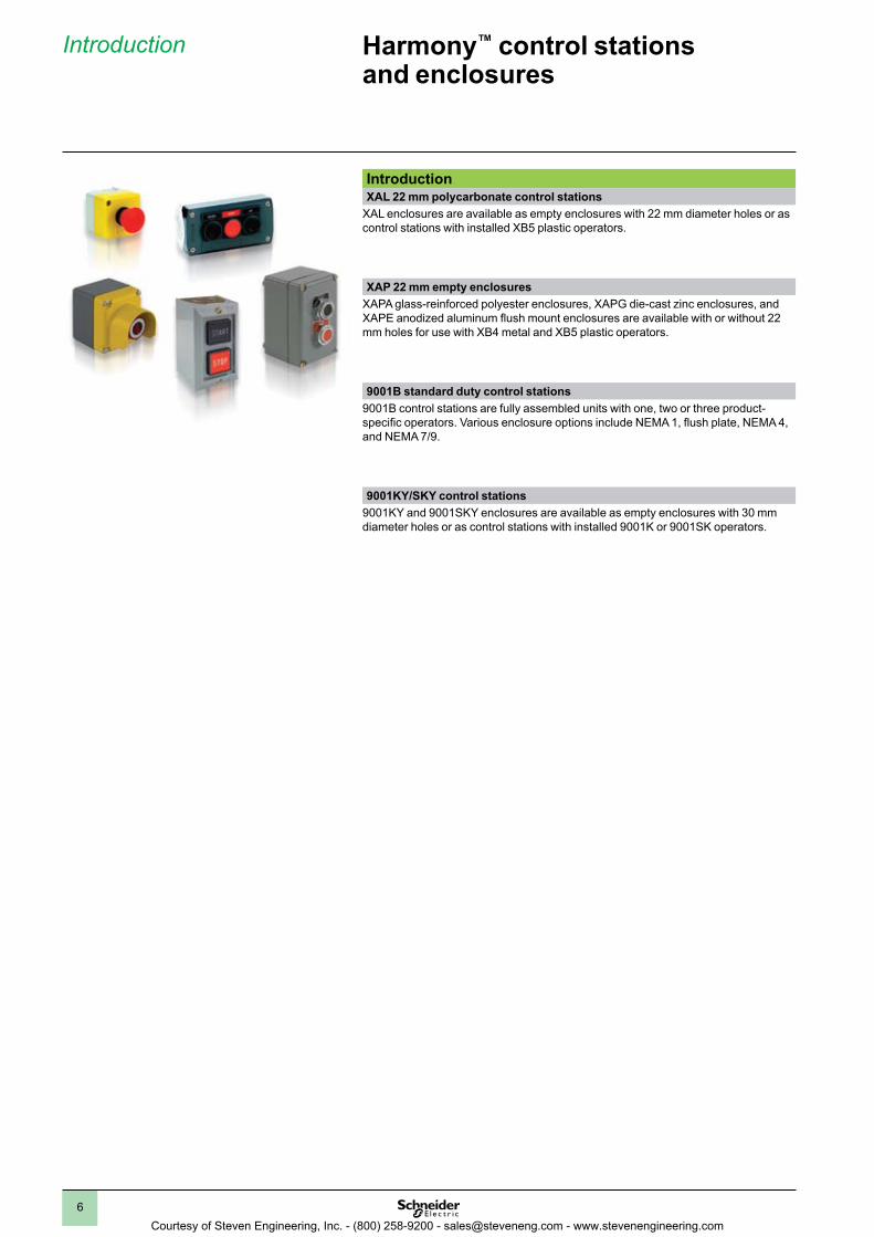
IntroductionXAL 22 mm polycarbonate control stations
XAL enclosures are available as empty enclosures with 22 mm diameter holes or as control stations with installed XB5 plastic operators.
XAP 22 mm empty enclosuresXAPA glass-reinforced polyester enclosures, XAPG die-cast zinc enclosures, and XAPE anodized aluminum flush mount enclosures are available with or without 22 mm holes for use with XB4 metal and XB5 plastic operators.
9001B standard duty control stations9001B control stations are fully assembled units with one, two or three product-specific operators. Various enclosure options include NEMA 1, flush plate, NEMA 4, and NEMA 7/9.
9001KY/SKY control stations9001KY and 9001SKY enclosures are available as empty enclosures with 30 mm diameter holes or as control stations with installed 9001K or 9001SK operators.
Courtesy of Steven Engineering, Inc. - (800) 258-9200 - [email protected] - www.stevenengineering.com
1
2
3
4
5
6
7
8
9
10
7
6
7
7
7
5
8
7
7
7
7
7
7
4
3
3
2
2
1
1
1
Harmony™ control stations and enclosuresXAL 22 mm control stations
Components
Components
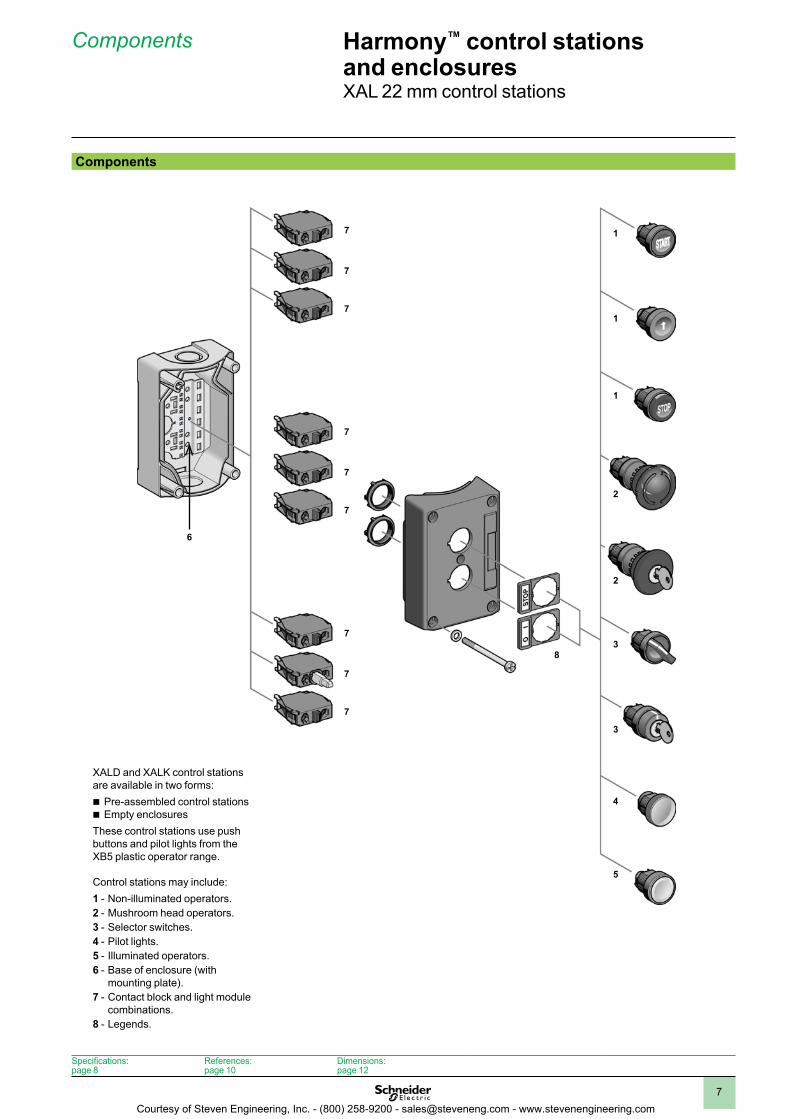
XALD and XALK control stations are available in two forms:b Pre-assembled control stationsb Empty enclosuresThese control stations use push buttons and pilot lights from the XB5 plastic operator range.
Control stations may include:1 - Non-illuminated operators.2 - Mushroom head operators.3 - Selector switches.4 - Pilot lights.5 - Illuminated operators.6 - Base of enclosure (with
mounting plate).7 - Contact block and light module
combinations.8 - Legends.
Specifications:page 8
References:page 10
Dimensions:page 12
Courtesy of Steven Engineering, Inc. - (800) 258-9200 - [email protected] - www.stevenengineering.com
1
2
3
4
5
6
7
8
9
10
8
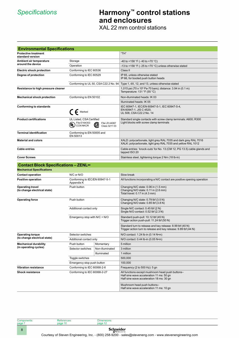
Environmental SpecificationsProtective treatment standard version
“TH”
Ambient air temperaturearound the device
Storage -40 to +158 °F (- 40 to +70 °C)Operation -13 to +158 °F (- 25 to +70 °C) unless otherwise stated
Electric shock protection Conforming to IEC 60536 Class II
Degree of protection Conforming to IEC 60529 IP 65, unless otherwise statedIP 66, for booted push button heads
Conforming to UL 50, CSA C22.2 No. 94 Type 1, 4X, 12, and 13, unless otherwise stated
Resistance to high pressure cleaner 1,015 psi (70 x 105 Pa-70 bars); distance: 3.94 in (0.1 m)Temperature: 131 °F (55 °C)
Mechanical shock protection Conforming to EN 50102 Non-illuminated heads: IK 03
Illuminated heads: IK 05
Conforming to standards IEC 60947-1, IEC/EN 60947-5-1, IEC 60947-5-4, EN 60947-1, JIS C 4520,UL 508, CSA C22.2 No. 14
Product certifications UL Listed, CSA Certified Standard single contacts with screw clamp terminals: A600; R300Light blocks with screw clamp terminals
Terminal identification Conforming to EN 50005 and EN 50013
Material and colors XALD: polycarbonate, light grey RAL 7035 and dark grey RAL 7016XALK: polycarbonate, light grey RAL 7035 and yellow RAL 1012
Cable entries Cable entries: ‘knock-outs’ for No. 13 (CM 12, PG 13.5) cable glands and tapped ISO 20
Cover Screws Stainless steel, tightening torque 2 Nm (18 lb-in)
Contact Block Specifications – ZENL••Mechanical Specifications
Contact operation N/C or N/O Slow break
Positive operation Conforming to IEC/EN 60947-5-1 Appendix K
All functions incorporating a N/C contact are positive opening operation
Operating travel (to change electrical state)
Push button Changing N/C state: 0.06 in (1.5 mm)Changing N/O state: 0.11 in (2.6 mm)Total travel: 0.17 in (4.3 mm)
Operating force Push button Changing N/C state: 0.79 lbf (3.5 N)Changing N/O state: 0.85 lbf (3.8 N)
Additional contact only Single N/C contact: 0.45 lbf (2 N)Single N/O contact: 0.52 lbf (2.3 N)
Emergency stop with N/C + N/O Standard push-pull: 10.12 lbf (45 N)Trigger action push-pull: 11.24 lbf (50 N)
Standard turn to release and key release: 8.99 lbf (40 N)Trigger action turn to release and key release: 9.89 lbf (44 N)
Operating torque (to change electrical state)
Selector switches N/O contact: 1.24 lb-in (0.14 N•m)
Additional contact only N/O contact: 0.44 lb-in (0.05 N•m)
Mechanical durability (in operating cycles)
Push button Momentary 5 million
Selector switches Non-illuminated 3 million
Illuminated 1 million
Toggle switches 500,000
Emergency stop push button 100,000
Vibration resistance Conforming to IEC 60068-2-6 Frequency (2 to 500 Hz): 5 gn
Shock resistance Conforming to IEC 60068-2-27 All functions except mushroom head push buttons–Half sine wave acceleration 11 ms: 50 gnHalf sine wave acceleration 18 ms: 30 gn
Mushroom head push buttons–Half sine wave acceleration 11 ms: 10 gn
Marked
File E164353 CCN NKCR
File LR 44087 Class 3211 03®�
Harmony™ control stations and enclosuresXAL 22 mm control stations
Specifications
Components:page 7
References:page 10
Dimensions:page 12
Courtesy of Steven Engineering, Inc. - (800) 258-9200 - [email protected] - www.stevenengineering.com
1
2
3
4
5
6
7
8
9
10
9
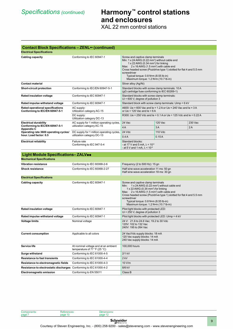
Contact Block Specifications – ZENL•• (continued)Electrical Specifications
Cabling capacity Conforming to IEC 60947-1 Screw and captive clamp terminalsMin: 1 x 24 AWG (0.22 mm2) without cable end
1 x 22 AWG (0.34 mm2) for linkingMax: 2 x 16 AWG (1.5 mm2) with cable endCross headed screw (Pozidrive type 1) slotted for flat 4 and 5.5 mm screwdriver Typical torque: 0.8 N•m (8.55 lb-in) Maximum torque: 1.2 N•m (10.7 lb-in)
Contact material Silver alloy (Ag/Ni)
Short-circuit protection Conforming to IEC/EN 60947-5-1 Standard blocks with screw clamp terminals: 10 A (gG cartridge fuse conforming to IEC 60269-1)
Rated insulation voltage Conforming to IEC 60947-1 Standard blocks with screw clamp terminals: Ui = 600 V, degree of pollution 3
Rated impulse withstand voltage Conforming to IEC 60947-1 Standard block with screw clamp terminals: Uimp = 6 kV
Rated operational specifications Conforming to IEC/EN 60947-5-1
AC supply: Utilization category AC-15
A600: Ue = 600 Vac and le = 1.2 A or Ue = 240 Vac and le = 3 A or Ue = 120 Vac and le = 6 A
DC supply: Utilization category DC-13
R300: Ue = 250 Vdc and le = 0.1 A or Ue = 125 Vdc and le = 0.22 A
Electrical durability Conforming to IEC/EN 60947-5-1 Appendix C Operating rate 3600 operating cycles/hour . Load factor: 0 .5
AC supply for 1 million operating cycles, utilization category AC-15
24 Vac 120 Vac 230 Vac
4 A 3 A 2 A
DC supply for 1 million operating cycles, utilization category DC-13
24 Vdc 110 Vdc
0.4 A 0.15 A
Electrical reliability Failure rate Conforming to IEC 947-5-4
Standard blocks: - at 17 V and 5 mA, l < 10-8
- at 5 V and 1 mA, l < 10-6
Light Module Specifications– ZALVppMechanical Specifications
Vibration resistance Conforming to IEC 60068-2-6 Frequency (2 to 500 Hz): 15 gn
Shock resistance Conforming to IEC 60068-2-27 Half sine wave acceleration 11 ms: 50 gnHalf sine wave acceleration 18 ms: 30 gn
Electrical Specifications
Cabling capacity Conforming to IEC 60947-1 Screw and captive clamp terminalsMin: 1 x 24 AWG (0.22 mm2) without cable end 1 x 22 AWG (0.34 mm2) for linkingMax: 2 x 16 AWG (1.5 mm2) with cable endCross headed screw (Pozidrive type 1) slotted for flat 4 and 5.5 mm screwdriver Typical torque: 0.8 N•m (8.55 lb-in) Maximum torque: 1.2 N•m (10.7 lb-in)
Rated insulation voltage Conforming to IEC 60947-1 Pilot light blocks with protected LED: Ui = 250 V, degree of pollution 3
Rated impulse withstand voltage Conforming to IEC 60947-1 Pilot light blocks with protected LED: Uimp = 4 kV
Voltage limits Nominal voltage 24 V: 21.6 to 24.6 Vac; 19.2 to 30 Vdc120V: 102 to 132 Vac240V: 195 to 264 Vac
Current consumption Applicable to all colors 24 Vac/Vdc supply blocks: 18 mA120 Vac supply blocks: 14 mA240 Vac supply blocks: 14 mA
Service life At nominal voltage and at an ambient temperature of 77 °F (25 °C)
100,000 hours
Surge withstand Conforming to IEC 61000-4-5 2/1 kV
Resistance to fast transients Conforming to IEC 61000-4-4 2 kV
Resistance to electromagnetic fields Conforming to IEC 61000-4-3 10 V/m
Resistance to electrostatic discharges Conforming to IEC 61000-4-2 8/6 kV
Electromagnetic emission Conforming to EN 55011 Class B
Harmony™ control stations and enclosuresXAL 22 mm control stations
Specifications (continued)
Components:page 7
References:page 10
Dimensions:page 12
Courtesy of Steven Engineering, Inc. - (800) 258-9200 - [email protected] - www.stevenengineering.com
1
2
3
4
5
6
7
8
9
10
10
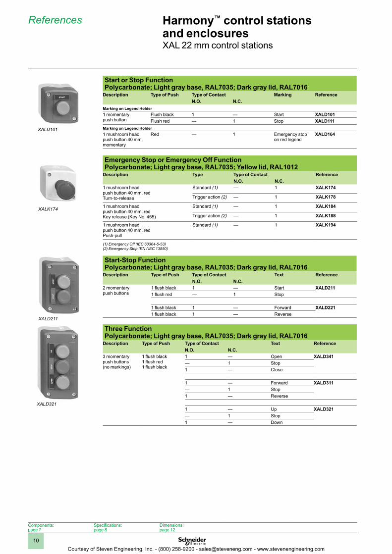
Start or Stop Function Polycarbonate; Light gray base, RAL7035; Dark gray lid, RAL7016
Description Type of Push Type of Contact Marking ReferenceN .O . N .C .
Marking on Legend Holder1 momentary push button
Flush black 1 — Start XALD101Flush red — 1 Stop XALD111
Marking on Legend Holder1 mushroom head push button 40 mm, momentary
Red — 1 Emergency stop on red legend
XALD164
Emergency Stop or Emergency Off Function Polycarbonate; Light gray base, RAL7035; Yellow lid, RAL1012
Description Type Type of Contact ReferenceN .O . N .C .
1 mushroom headpush button 40 mm, redTurn-to-release
Standard (1) — 1 XALK174
Trigger action (2) — 1 XALK178
1 mushroom head push button 40 mm, redKey release (Key No. 455)
Standard (1) — 1 XALK184
Trigger action (2) — 1 XALK188
1 mushroom head push button 40 mm, redPush-pull
Standard (1) — 1 XALK194
(1) Emergency Off (IEC 60364-5-53)(2) Emergency Stop (EN / IEC 13850)
Start-Stop Function Polycarbonate; Light gray base, RAL7035; Dark gray lid, RAL7016
Description Type of Push Type of Contact Text ReferenceN .O . N .C .
2 momentarypush buttons
1 flush black 1 — Start XALD2111 flush red — 1 Stop
1 flush black 1 — Forward XALD2211 flush black 1 — Reverse
Three Function Polycarbonate; Light gray base, RAL7035; Dark gray lid, RAL7016
Description Type of Push Type of Contact Text ReferenceN .O . N .C .
3 momentary push buttons(no markings)
1 flush black1 flush red1 flush black
1 — Open XALD341— 1 Stop1 — Close
1 — Forward XALD311— 1 Stop1 — Reverse
1 — Up XALD321— 1 Stop1 — Down
XALD101
XALK174
XALD211
XALD321
Harmony™ control stations and enclosuresXAL 22 mm control stations
References
Components:page 7
Specifications:page 8
Dimensions:page 12
Courtesy of Steven Engineering, Inc. - (800) 258-9200 - [email protected] - www.stevenengineering.com
1
2
3
4
5
6
7
8
9
10
11
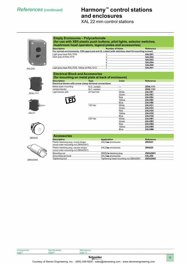
Empty Enclosures – Polycarbonate (for use with XB5 plastic push buttons, pilot lights, selector switches, mushroom head operators, legend plates and accessories)
Description Number of Holes ReferenceFor normal environments, CSA approved and UL Listed (with stainless steel lid mounting screws)Light gray base RAL7035Dark gray lid RAL7016
1 XALD012 XALD023 XALD034 XALD045 XALD05
Light gray base RAL7035, Yellow lid RAL1012 1 XALK01
Electrical Block and Accessories (for mounting on metal plate at back of enclosure)
Description Type Color ReferenceElectrical blocks with screw clamp terminal connectionsMetal-plate-mounting contact blocks
N.O. contact — ZENL1111N.C. contact — ZENL1121
Light blocks with 24 Vac/Vdc White ZALVB1Green ZALVB3Red ZALVB4Yellow ZALVB5Blue ZALVB6
120 Vac White ZALVG1Green ZALVG3Red ZALVG4Yellow ZALVG5Blue ZALVG6
230 Vac White ZALVM1Green ZALVM3Red ZALVM4Yellow ZALVM5Blue ZALVM6
AccessoriesDescription Application ReferencePlastic blanking plug, round-shape (must order mounting nut ZB5AZ901)
XALDpp enclosures ZB5SZ3
Plastic blanking plug, square-shape (must order mounting nut ZB5AZ901)
XALDpp enclosures ZB5SZ5
Mounting nut ZB5SZp blanking plug ZB5AZ901Grounding terminal XALDpp enclosures XALZ09Tightening tool Tightening head mounting nut ZB5AZ901 ZB5AZ905
Harmony™ control stations and enclosuresXAL 22 mm control stations
References (continued)
XALD02
ZENL1111
ZALV••
ZB5SZ3
ZB5AZ905
Components:page 7
Specifications:page 8
Dimensions:page 12
Courtesy of Steven Engineering, Inc. - (800) 258-9200 - [email protected] - www.stevenengineering.com
1
2
3
4
5
6
7
8
9
10
12
Harmony™ control stations and enclosuresXAL 22 mm control stations
Dimensions
Dual Dimensions: in (mm)
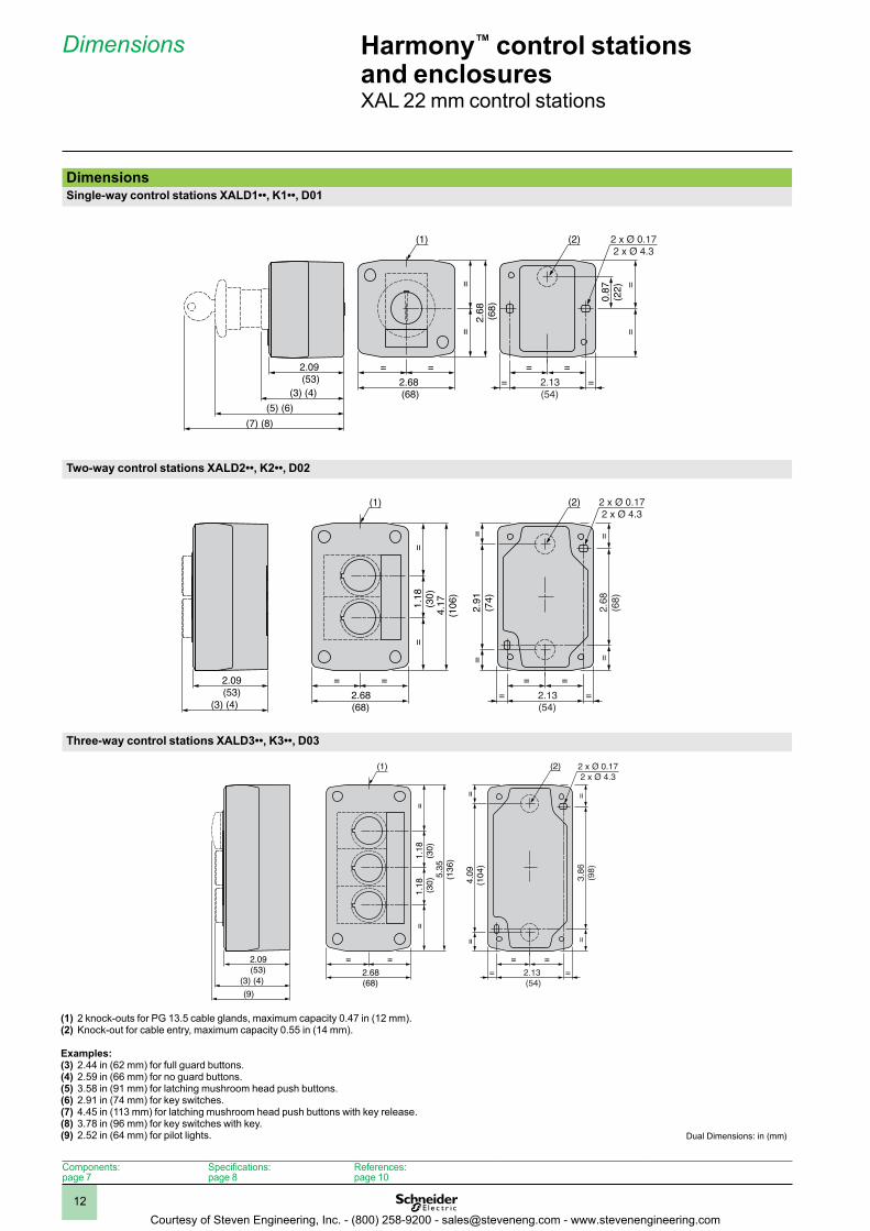
(1) 2 knock-outs for PG 13.5 cable glands, maximum capacity 0.47 in (12 mm).(2) Knock-out for cable entry, maximum capacity 0.55 in (14 mm).
Examples:(3) 2.44 in (62 mm) for full guard buttons.(4) 2.59 in (66 mm) for no guard buttons.(5) 3.58 in (91 mm) for latching mushroom head push buttons.(6) 2.91 in (74 mm) for key switches.(7) 4.45 in (113 mm) for latching mushroom head push buttons with key release.(8) 3.78 in (96 mm) for key switches with key.(9) 2.52 in (64 mm) for pilot lights.
DimensionsSingle-way control stations XALD1••, K1••, D01
Two-way control stations XALD2••, K2••, D02
Three-way control stations XALD3••, K3••, D03
Single-way control stations XALD1••, K1••, D01
2.09(53)
(5) (6)(3) (4)
(7) (8)
=2.68(68)
2.13(54)
= ===
=
=
0.87
(22)
=
(1)
=2.
68 (68)
=
(2) 2 x Ø 0.172 x Ø 4.3
20D ,••2K ,••2DLAX snoitats lortnoc yaw-owT
2.09(53)
(3) (4)
=2.68(68)
=
=1.
18(3
0)4.
17(1
06)
=
2.13(54)
===
=
(1) 2 x Ø 0.172 x Ø 4.3
=2.
68(6
8)=
2.91
(74)
==
(2)
Three-way control stations XALD3••, K3••, D03
2.09(53)
(3) (4)(9)
=2.68(68)
=
=1.
18 (30)
1.18
(30)
5.35
(136
)
=
2.13(54)
===
=
(1) 2 x Ø 0.172 x Ø 4.3
=3.
86(9
8)=
4.09
(104
)=
=
(2)
Components:page 7
Specifications:page 8
References:page 10
Courtesy of Steven Engineering, Inc. - (800) 258-9200 - [email protected] - www.stevenengineering.com
1
2
3
4
5
6
7
8
9
10
13
Harmony™ control stations and enclosuresXAL 22 mm control stations
Dimensions (continued)
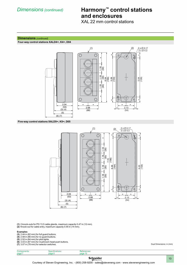
(1) 2 knock-outs for PG 13.5 cable glands, maximum capacity 0.47 in (12 mm).(2) Knock-out for cable entry, maximum capacity 0.55 in (14 mm).
Examples:(3) 2.44 in (62 mm) for full guard buttons.(4) 2.59 in (66 mm) for no guard buttons.(5) 2.52 in (64 mm) for pilot lights.(6) 3.43 in (87 mm) for mushroom head push buttons.(7) 3.07 in (78 mm) for selector switches. Dual Dimensions: in (mm)
Dimensions (continued)Four-way control stations XALD4••, K4••, D04
Five-way control stations XALD5••, K5••, D05
40D ,••4K ,••4DLAX snoitats lortnoc yaw-ruoF
2.04(53)
(3) (4)(5)
(6) (7)
=2.68(68)
=
=1.
18(3
0)1.
18(3
0)1.
18 (30)
6.54
(166
)
=
2.13(54)
===
=
(1) 2 x Ø 0.172 x Ø 4.3
=5.
04(1
28)
=
5.28
(134
)=
=
(2)
Five-way control stations XALD5••, K5••, D05
2.09(53)
(3) (4)(5)
(6) (7)
=2.68(68)
=
=1.
18 (30)
1.18
(30)
1.18
(30)
1.18
(30)
7.72
(196
)
=
2.13(54)
===
=
(1)2 x Ø 4.32 x Ø 0.17
=6.
22(1
58)
=
6.46
(164
)=
=
(2)
Components:page 7
Specifications:page 8
References:page 10
Courtesy of Steven Engineering, Inc. - (800) 258-9200 - [email protected] - www.stevenengineering.com
1
2
3
4
5
6
7
8
9
10
14
Harmony™ control stations and enclosuresXAP 22 mm enclosures
Components
6
5
8
7
7
7
7
4
3
3
2
2
1
1
1
Components
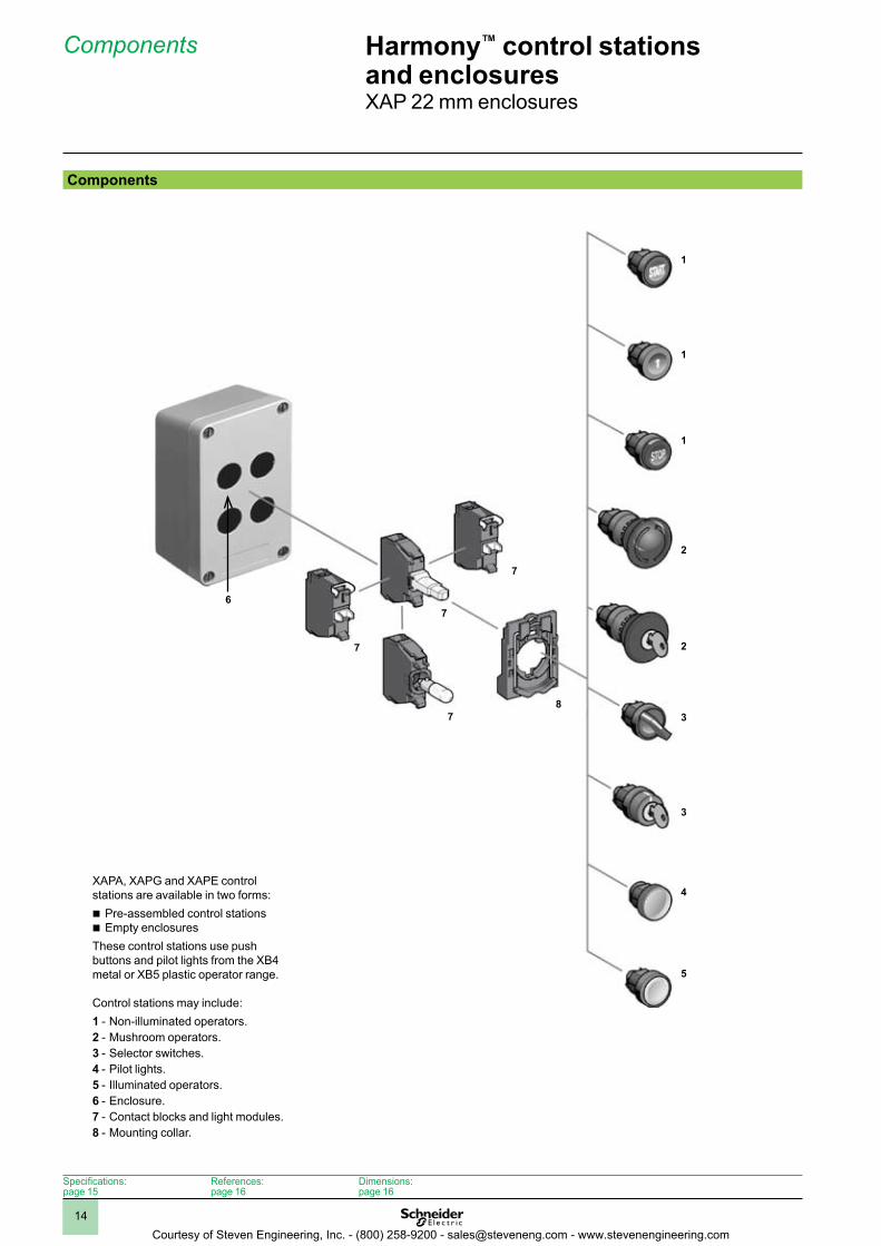
XAPA, XAPG and XAPE control stations are available in two forms:b Pre-assembled control stationsb Empty enclosuresThese control stations use push buttons and pilot lights from the XB4 metal or XB5 plastic operator range.
Control stations may include:1 - Non-illuminated operators.2 - Mushroom operators.3 - Selector switches.4 - Pilot lights.5 - Illuminated operators.6 - Enclosure.7 - Contact blocks and light modules.8 - Mounting collar.
Specifications:page 15
References:page 16
Dimensions:page 16
Courtesy of Steven Engineering, Inc. - (800) 258-9200 - [email protected] - www.stevenengineering.com
1
2
3
4
5
6
7
8
9
10
15
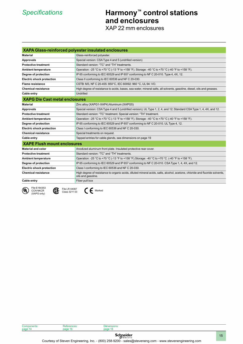
XAPA Glass-reinforced polyester insulated enclosuresMaterial Glass-reinforced polyester.
Approvals Special version: CSA Type 4 and 5 (undrilled version)
Protective treatment Standard version: “TC” and “TH” treatments.
Ambient temperature Operation: -25 °C to +70 °C (-13 °F to +158 °F). Storage: -40 °C to +70 °C (-40 °F to +158 °F).
Degree of protection IP 65 conforming to IEC 60529 and IP 657 conforming to NF C 20-010. Type 4, 4X, 12.
Electric shock protection Class II conforming to IEC 60536 and NF C 20-030.
Flame resistance CSTB: M3, NF C 20-455: 850°C, IEC 60092: 960 °C, UL 94: VO.
Chemical resistance High degree of resistance to acids, bases, sea water, mineral salts, all solvents, gasoline, diesel, oils and greases.
Cable entry Undrilled
XAPG Die Cast metal enclosuresMaterial Zinc alloy (XAPG1-XAP4) Aluminum (XAPG5)
Approvals Special version: CSA Type 4 and 5 (undrilled version); UL Type 1, 2, 4, and 12; Standard CSA Type 1, 4, 4X, and 12.
Protective treatment Standard version: “TC” treatment. Special version: “TH” treatment.
Ambient temperature Operation: -25 °C to +70 °C (-13 °F to +158 °F). Storage: -40 °C to +70 °C (-40 °F to +158 °F).
Degree of protection IP 65 conforming to IEC 60529 and IP 657 conforming to NF C 20-010. UL Type 4, 12.
Electric shock protection Class I conforming to IEC 60536 and NF C 20-030.
Chemical resistance Special treatments on request.
Cable entry Tapped entries for cable glands, see dimensions on page 19
XAPE Flush mount enclosuresMaterial and color Anodized aluminum front plate. Insulated protective rear cover.
Protective treatment Standard version: “TC” and “TH” treatments.
Ambient temperature Operation: -25 °C to +70 °C (-13 °F to +158 °F).Storage: -40 °C to +70 °C. (-40 °F to +158 °F).
Degree of protection IP 65 conforming to IEC 60529 and IP 657 conforming to NF C 20-010. CSA Type 1, 4, 4X, and 12.
Electric shock protection Class I conforming to IEC 60536 and NF C 20-030.
Chemical resistance High degree of resistance to organic acids, diluted mineral acids, salts, alcohol, acetone, chloride and fluoride solvents, oils and gasoline.
Cable entry Fiber pull box
Harmony™ control stations and enclosuresXAP 22 mm enclosures
Specifications
®�
File E164353CCN NKCR(XAPG only)
File LR 44087Class 3211 03 Marked
Components:page 14
References:page 16
Dimensions:page 16
Courtesy of Steven Engineering, Inc. - (800) 258-9200 - [email protected] - www.stevenengineering.com
1
2
3
4
5
6
7
8
9
10
16
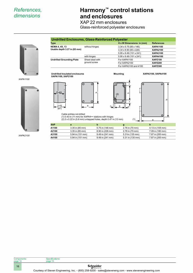
Undrilled Enclosures, Glass-Reinforced PolyesterType H x W Dimensions: in (mm) ReferencesNEMA 4, 4X, 13Usable depth 3 .27 in (83 mm)
without hinges 3.34 x 5.75 (85 x 146) XAPA11003.34 x 8.90 (85 x 226) XAPA21005.95 x 9.49 (151 x 241) XAPA3100
with hinges 5.95 x 9.49 (151 x 241) XAPA4100Undrilled Grounding Plate Sheet steel with
ground screwFor XAPA1100 XAPZ100For XAPA2100 XAPZ200For XAPA3100 and 4100 XAPZ300
XAP a b g hA1100 3.35 in (85 mm) 5.75 in (146 mm) 2.76 in (70 mm) 4.13 in (105 mm)A2100 3.35 in (85 mm) 8.90 in (226 mm) 2.76 in (70 mm) 7.09 in (180 mm)A3100 5.94 in (151 mm) 9.49 in (241 mm) 5.31in (135 mm) 7.87 in (200 mm)A4100 5.94 in (151 mm) 9.49 in (241 mm) 5.31 in (135 mm) 7.87 in (200 mm)
Harmony™ control stations and enclosuresXAP 22 mm enclosuresGlass-reinforced polyester enclosures
References, dimensions
P=83
3.43(87)
b
a
h(2)
g
(1)
==
==
b
a
Undrilled Insulated enclosuresXAPA1100, XAP2100
Mounting XAPA3100, XAPA4100
Components:page 14
Specifications:page 15
XAPA1100
XAPA2100
Cable entries not drilled(1) 0.43 in (11 mm) for XAPA4••• stations with hinges(2) 2 x 0.22 in (5.6 mm) untapped holes, depth 0.47 in (12 mm)
Courtesy of Steven Engineering, Inc. - (800) 258-9200 - [email protected] - www.stevenengineering.com
1
2
3
4
5
6
7
8
9
10
17
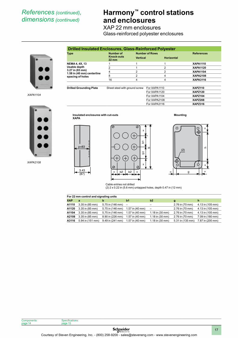
Drilled Insulated Enclosures, Glass-Reinforced PolyesterType Number of
Knock-outs22 mm
Number of Rows ReferencesVertical Horizontal
NEMA 4, 4X, 13Usable depth3 .27 in (83 mm)1 .58 in (40 mm) centerlinespacing of holes
1 1 1 XAPA11102 1 2 XAPA11204 2 2 XAPA11048 2 4 XAPA210816 4 4 XAPA3116
Drilled Grounding Plate Sheet steel with ground screw For XAPA1110 XAPZ110
For XAPA1120 XAPZ120For XAPA1104 XAPZ104For XAPA2108 XAPZ208For XAPA3116 XAPZ316
For 22 mm control and signaling unitsXAP a b b1 b2 g hA1110 3.35 in (85 mm) 5.75 in (146 mm) – – 2.76 in (70 mm) 4.13 in (105 mm)A1120 3.35 in (85 mm) 5.75 in (146 mm) 1.57 in (40 mm) – 2.76 in (70 mm) 4.13 in (105 mm)A1104 3.35 in (85 mm) 5.75 in (146 mm) 1.57 in (40 mm) 1.18 in (30 mm) 2.76 in (70 mm) 4.13 in (105 mm)A2108 3.35 in (85 mm) 8.90 in (226 mm) 1.57 in (40 mm) 1.18 in (30 mm) 2.76 in (70 mm) 7.09 in (180 mm)A3116 5.94 in (151 mm) 9.49 in (241 mm) 1.57 in (40 mm) 1.18 in (30 mm) 5.31 in (135 mm) 7.87 in (200 mm)
Harmony™ control stations and enclosuresXAP 22 mm enclosuresGlass-reinforced polyester enclosures
References (continued), dimensions (continued)
p=83
3.43(87) b2
b1b1
==
b
b2 === =
==
h
g
(2)
Insulated enclosures with cut-outsXAPA
Mounting
Components:page 14
Specifications:page 15
XAPA1104
XAPA2108
Cable entries not drilled(2) 2 x 0.22 in (5.6 mm) untapped holes, depth 0.47 in (12 mm)
Courtesy of Steven Engineering, Inc. - (800) 258-9200 - [email protected] - www.stevenengineering.com
1
2
3
4
5
6
7
8
9
10
18
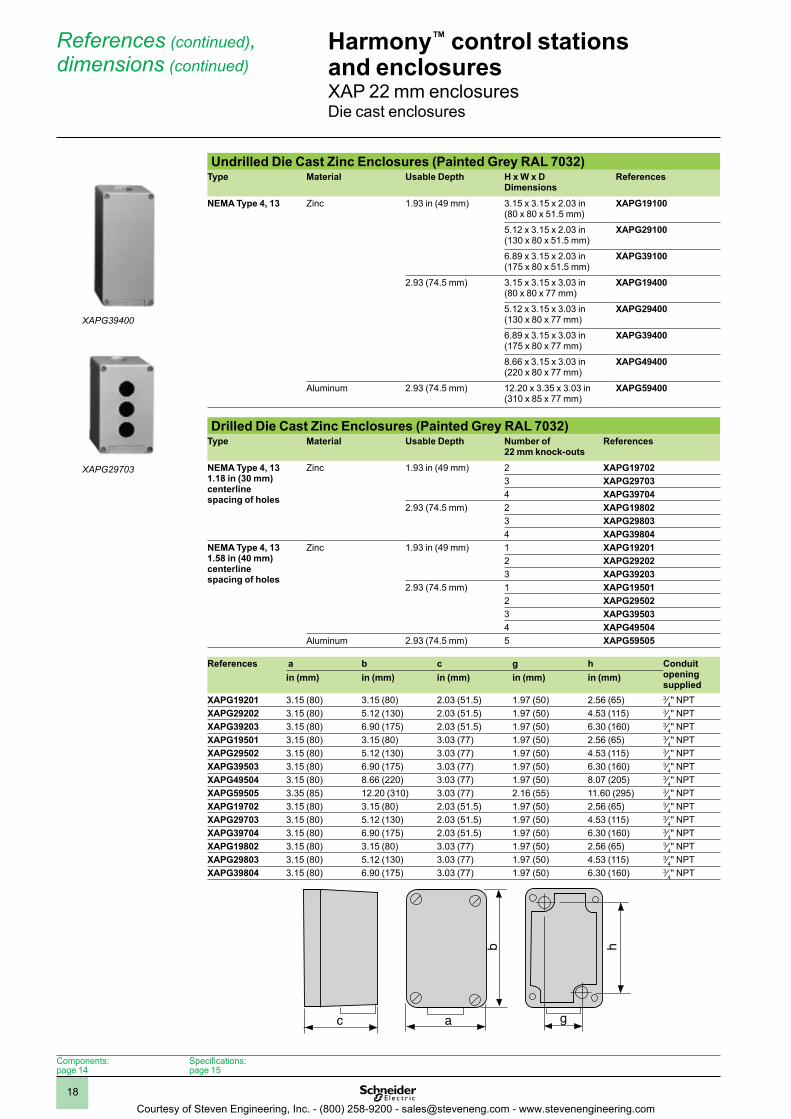
Undrilled Die Cast Zinc Enclosures (Painted Grey RAL 7032)Type Material Usable Depth H x W x D
Dimensions References
NEMA Type 4, 13 Zinc 1.93 in (49 mm) 3.15 x 3.15 x 2.03 in (80 x 80 x 51.5 mm)
XAPG19100
5.12 x 3.15 x 2.03 in (130 x 80 x 51.5 mm)
XAPG29100
6.89 x 3.15 x 2.03 in (175 x 80 x 51.5 mm)
XAPG39100
2.93 (74.5 mm) 3.15 x 3.15 x 3.03 in (80 x 80 x 77 mm)
XAPG19400
5.12 x 3.15 x 3.03 in (130 x 80 x 77 mm)
XAPG29400
6.89 x 3.15 x 3.03 in (175 x 80 x 77 mm)
XAPG39400
8.66 x 3.15 x 3.03 in (220 x 80 x 77 mm)
XAPG49400
Aluminum 2.93 (74.5 mm) 12.20 x 3.35 x 3.03 in (310 x 85 x 77 mm)
XAPG59400
Drilled Die Cast Zinc Enclosures (Painted Grey RAL 7032) Type Material Usable Depth Number of
22 mm knock-outsReferences
NEMA Type 4, 131 .18 in (30 mm) centerline spacing of holes
Zinc 1.93 in (49 mm) 2 XAPG197023 XAPG297034 XAPG39704
2.93 (74.5 mm) 2 XAPG198023 XAPG298034 XAPG39804
NEMA Type 4, 131 .58 in (40 mm) centerline spacing of holes
Zinc 1.93 in (49 mm) 1 XAPG192012 XAPG292023 XAPG39203
2.93 (74.5 mm) 1 XAPG195012 XAPG295023 XAPG395034 XAPG49504
Aluminum 2.93 (74.5 mm) 5 XAPG59505
References a b c g h Conduit openingsupplied
in (mm) in (mm) in (mm) in (mm) in (mm)
XAPG19201 3.15 (80) 3.15 (80) 2.03 (51.5) 1.97 (50) 2.56 (65) 3⁄4" NPTXAPG29202 3.15 (80) 5.12 (130) 2.03 (51.5) 1.97 (50) 4.53 (115) 3⁄4" NPTXAPG39203 3.15 (80) 6.90 (175) 2.03 (51.5) 1.97 (50) 6.30 (160) 3⁄4" NPTXAPG19501 3.15 (80) 3.15 (80) 3.03 (77) 1.97 (50) 2.56 (65) 3⁄4" NPTXAPG29502 3.15 (80) 5.12 (130) 3.03 (77) 1.97 (50) 4.53 (115) 3⁄4" NPTXAPG39503 3.15 (80) 6.90 (175) 3.03 (77) 1.97 (50) 6.30 (160) 3⁄4" NPTXAPG49504 3.15 (80) 8.66 (220) 3.03 (77) 1.97 (50) 8.07 (205) 3⁄4" NPTXAPG59505 3.35 (85) 12.20 (310) 3.03 (77) 2.16 (55) 11.60 (295) 3⁄4" NPTXAPG19702 3.15 (80) 3.15 (80) 2.03 (51.5) 1.97 (50) 2.56 (65) 3⁄4" NPTXAPG29703 3.15 (80) 5.12 (130) 2.03 (51.5) 1.97 (50) 4.53 (115) 3⁄4" NPTXAPG39704 3.15 (80) 6.90 (175) 2.03 (51.5) 1.97 (50) 6.30 (160) 3⁄4" NPTXAPG19802 3.15 (80) 3.15 (80) 3.03 (77) 1.97 (50) 2.56 (65) 3⁄4" NPTXAPG29803 3.15 (80) 5.12 (130) 3.03 (77) 1.97 (50) 4.53 (115) 3⁄4" NPTXAPG39804 3.15 (80) 6.90 (175) 3.03 (77) 1.97 (50) 6.30 (160) 3⁄4" NPT
Harmony™ control stations and enclosuresXAP 22 mm enclosuresDie cast enclosures
References (continued), dimensions (continued)
c a
g
h
b
c a
g
h
b
Components:page 14
Specifications:page 15
XAPG39400
XAPG29703
Courtesy of Steven Engineering, Inc. - (800) 258-9200 - [email protected] - www.stevenengineering.com
1
2
3
4
5
6
7
8
9
10
19
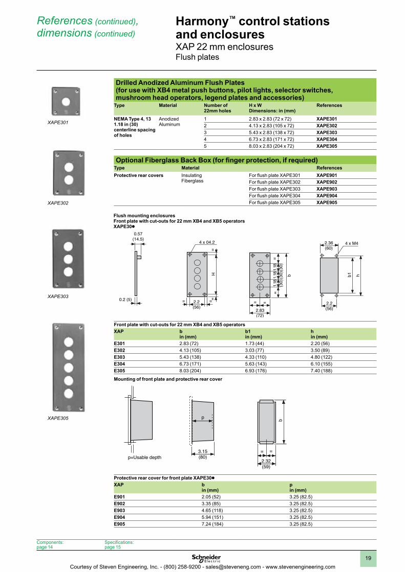
Drilled Anodized Aluminum Flush Plates (for use with XB4 metal push buttons, pilot lights, selector switches, mushroom head operators, legend plates and accessories)
Type Material Number of22mm holes
H x WDimensions: in (mm)
References
NEMA Type 4, 131 .18 in (30) centerline spacing of holes
AnodizedAluminum
1 2.83 x 2.83 (72 x 72) XAPE3012 4.13 x 2.83 (105 x 72) XAPE3023 5.43 x 2.83 (138 x 72) XAPE3034 6.73 x 2.83 (171 x 72) XAPE3045 8.03 x 2.83 (204 x 72) XAPE305
Optional Fiberglass Back Box (for finger protection, if required)Type Material ReferencesProtective rear covers Insulating
FiberglassFor flush plate XAPE301 XAPE901For flush plate XAPE302 XAPE902For flush plate XAPE303 XAPE903For flush plate XAPE304 XAPE904For flush plate XAPE305 XAPE905
Front plate with cut-outs for 22 mm XB4 and XB5 operatorsXAP b
in (mm)b1in (mm)
hin (mm)
E301 2.83 (72) 1.73 (44) 2.20 (56)E302 4.13 (105) 3.03 (77) 3.50 (89)E303 5.43 (138) 4.33 (110) 4.80 (122)E304 6.73 (171) 5.63 (143) 6.10 (155)E305 8.03 (204) 6.93 (176) 7.40 (188)
Protective rear cover for front plate XAPE30k XAP b
in (mm)pin (mm)
E901 2.05 (52) 3.25 (82.5)E902 3.35 (85) 3.25 (82.5)E903 4.65 (118) 3.25 (82.5)E904 5.94 (151) 3.25 (82.5)E905 7.24 (184) 3.25 (82.5)
Harmony™ control stations and enclosuresXAP 22 mm enclosuresFlush plates
References (continued), dimensions (continued)
= =
0.57(14.5)
0.2 (5)
4 x 04.2
2.2(56)
==
H
2.83(72)
2.2(56)
= =
==
b
1.18
(30)
1.18
(30)
1.18
(30)
b1 h
2.36(60)
4 x M4
p=Usable depth3.15(80)
p
2.32(59)
= =
b
= =
0.57(14.5)
0.2 (5)
4 x 04.2
2.2(56)
==
H
2.83(72)
2.2(56)
= =
==
b
1.18
(30)
1.18
(30)
1.18
(30)
b1 h
2.36(60)
4 x M4
p=Usable depth3.15(80)
p
2.32(59)
= =
b
Mounting of front plate and protective rear cover
Components:page 14
Specifications:page 15
XAPE301
XAPE302
XAPE303
XAPE305
Flush mounting enclosuresFront plate with cut-outs for 22 mm XB4 and XB5 operatorsXAPE30k
Courtesy of Steven Engineering, Inc. - (800) 258-9200 - [email protected] - www.stevenengineering.com
1
2
3
4
5
6
7
8
9
10
20
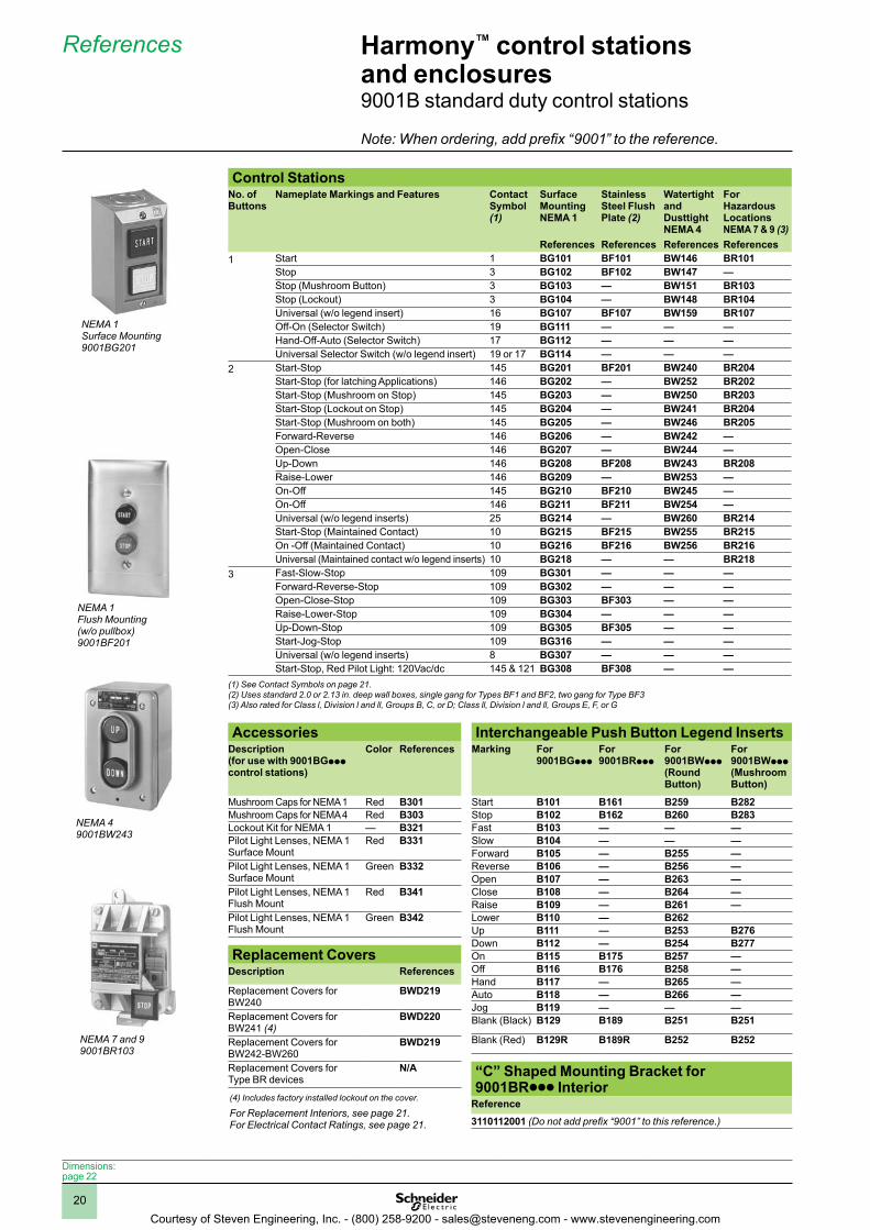
Control StationsNo . of Buttons
Nameplate Markings and Features Contact Symbol (1)
Surface Mounting NEMA 1
Stainless Steel Flush Plate (2)
Watertight and Dusttight NEMA 4
For Hazardous Locations NEMA 7 & 9 (3)
References References References References1 Start 1 BG101 BF101 BW146 BR101
Stop 3 BG102 BF102 BW147 —Stop (Mushroom Button) 3 BG103 — BW151 BR103Stop (Lockout) 3 BG104 — BW148 BR104Universal (w/o legend insert) 16 BG107 BF107 BW159 BR107Off-On (Selector Switch) 19 BG111 — — —Hand-Off-Auto (Selector Switch) 17 BG112 — — —Universal Selector Switch (w/o legend insert) 19 or 17 BG114 — — —
2 Start-Stop 145 BG201 BF201 BW240 BR204Start-Stop (for latching Applications) 146 BG202 — BW252 BR202Start-Stop (Mushroom on Stop) 145 BG203 — BW250 BR203Start-Stop (Lockout on Stop) 145 BG204 — BW241 BR204Start-Stop (Mushroom on both) 145 BG205 — BW246 BR205Forward-Reverse 146 BG206 — BW242 —Open-Close 146 BG207 — BW244 —Up-Down 146 BG208 BF208 BW243 BR208Raise-Lower 146 BG209 — BW253 —On-Off 145 BG210 BF210 BW245 —On-Off 146 BG211 BF211 BW254 —Universal (w/o legend inserts) 25 BG214 — BW260 BR214Start-Stop (Maintained Contact) 10 BG215 BF215 BW255 BR215On -Off (Maintained Contact) 10 BG216 BF216 BW256 BR216Universal (Maintained contact w/o legend inserts) 10 BG218 — — BR218
3 Fast-Slow-Stop 109 BG301 — — —Forward-Reverse-Stop 109 BG302 — — —Open-Close-Stop 109 BG303 BF303 — —Raise-Lower-Stop 109 BG304 — — —Up-Down-Stop 109 BG305 BF305 — —Start-Jog-Stop 109 BG316 — — —Universal (w/o legend inserts) 8 BG307 — — —Start-Stop, Red Pilot Light: 120Vac/dc 145 & 121 BG308 BF308 — —
(1) See Contact Symbols on page 21.(2) Uses standard 2.0 or 2.13 in. deep wall boxes, single gang for Types BF1 and BF2, two gang for Type BF3(3) Also rated for Class l, Division l and ll, Groups B, C, or D; Class ll, Division l and ll, Groups E, F, or G
Accessories Interchangeable Push Button Legend InsertsDescription(for use with 9001BGppp control stations)
Color References Marking For 9001BGppp
For 9001BRppp
For 9001BWppp (Round Button)
For 9001BWppp (Mushroom Button)
Mushroom Caps for NEMA 1 Red B301 Start B101 B161 B259 B282Mushroom Caps for NEMA 4 Red B303 Stop B102 B162 B260 B283Lockout Kit for NEMA 1 — B321 Fast B103 — — —Pilot Light Lenses, NEMA 1 Surface Mount
Red B331 Slow B104 — — —Forward B105 — B255 —
Pilot Light Lenses, NEMA 1 Surface Mount
Green B332 Reverse B106 — B256 —Open B107 — B263 —
Pilot Light Lenses, NEMA 1 Flush Mount
Red B341 Close B108 — B264 —Raise B109 — B261 —
Pilot Light Lenses, NEMA 1 Flush Mount
Green B342 Lower B110 — B262Up B111 — B253 B276Down B112 — B254 B277On B115 B175 B257 —Off B116 B176 B258 —Hand B117 — B265 —Auto B118 — B266 —Jog B119 — — —Blank (Black) B129 B189 B251 B251
Blank (Red) B129R B189R B252 B252
NEMA 1Surface Mounting9001BG201
NEMA 1Flush Mounting(w/o pullbox)9001BF201
NEMA 49001BW243
NEMA 7 and 99001BR103
Harmony™ control stations and enclosures9001B standard duty control stations
References
Dimensions:page 22
Note: When ordering, add prefix “9001” to the reference.
“C” Shaped Mounting Bracket for 9001BRppp Interior
Reference3110112001 (Do not add prefix “9001” to this reference.)
Replacement CoversDescription References
Replacement Covers for BW240
BWD219
Replacement Covers for BW241 (4)
BWD220
Replacement Covers for BW242-BW260
BWD219
Replacement Covers for Type BR devices
N/A
(4) Includes factory installed lockout on the cover.
For Replacement Interiors, see page 21.For Electrical Contact Ratings, see page 21.
Courtesy of Steven Engineering, Inc. - (800) 258-9200 - [email protected] - www.stevenengineering.com
1
2
3
4
5
6
7
8
9
10
21
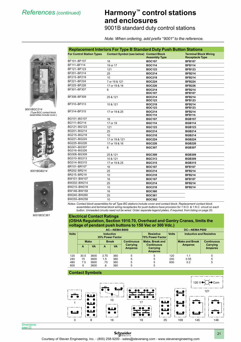
Replacement Interiors For Type B Standard Duty Push Button StationsFor Control Station Types Contact Symbol (see below) Contact Block
Assembly TypeTerminal Block Wiring Receptacle Type
BF101–BF107 16 BOC107 BFB107BF111–BF114 19 or 17 BOC114 BFB114BF121–BF123 121 BOC123 BFB123BF201–BF214 25 BOC214 BFB214BF215–BF218 10 BOC218 BFB214BF221–BF224 7 or 19 & 121 BOC224 BFB224BF225–BF226 17 or 19 & 16 BOC226 BFB226BF301–BF307 8 BOC214
BOC107BFB214BFB107
BF308–BF309 25 & 121 BOC214BOC123
BFB214BFB123
BF310–BF313 10 & 121 BOC218BOC123
BFB214BFB123
BF314–BF315 17 or 19 & 25 BOC214BOC114
BFB214BFB114
BG101–BG107 16 BGC107 BGB107BG111–BG114 17 or 19 BGC114 BGB114BG121–BG123 121 BGC123 BGB123BG201–BG214 25 BGC214 BGB214BG215–BG218 10 BGC218 BGB214BG221–BG224 17 or 19 & 121 BGC224 BGB224BG225–BG226 17 or 19 & 16 BGC226 BGB226BG301–BG307BG316–BG326
8 BGC307 BGB307
BG308–BG309 25 & 121 BGC309 BGB309BG310–BG313 10 & 121 BGC313 BGB309BG314–BG315 17 or 19 & 25 BGC315 BGB315BR101–BR107 16 BOC107 BFB107BR202–BR214 25 BOC214 BFB214BR215–BR219 10 BOC218 BFB214BW101–BW107 16 BOC107 BFB107BW202–BW214 25 BOC214 BFB214BW215–BW218 10 BOC218 BFB214BW146–BW159 16 BOC360BW240–BW260 25 BOC361BW255–BW258 10 BOC362Notes: Contact block assemblies for all Type BG stations include cover and contact block. Replacement contact block
assemblies and terminal block wiring receptacles for push buttons have provision for 1 N.O. & 1 N.C. circuit on each button. Unneeded circuits need not be wired. Order separate legend plates, if required, from listing on page 20.
Electrical Contact Ratings (OSHA Regulation, Section 1910 .70, Overhead and Gantry Cranes, limits the voltage of pendant push buttons to 150 Vac or 300 Vdc .)
AC—NEMA B600 DC—NEMA P600Volts Inductive
35% Power FactorResistive
75% Power FactorVolts Inductive and Resistive
Make Break Continuous Carrying Amperes
Make, Break and Continuous
Carrying Amperes
Make and Break Amperes
Continuous Carrying AmperesA VA A VA
120240480600
30.5 15
7.5 6
3600360036003600
3.751.5
.75 .6
360360360360
5555
5555
120240600
1.1 0.550.2
555
9001BGC214(Type BGC contact block
assemblies include cover.)
9001BGB214
9001BOC361
Harmony™ control stations and enclosures9001B standard duty control stations
References (continued)
Dimensions:page 22
Note: When ordering, add prefix “9001” to the reference.
Contact Symbols
1017
1916
1
3 8 25 109 145 146
121
120 V Com
Courtesy of Steven Engineering, Inc. - (800) 258-9200 - [email protected] - www.stevenengineering.com
1
2
3
4
5
6
7
8
9
10
22
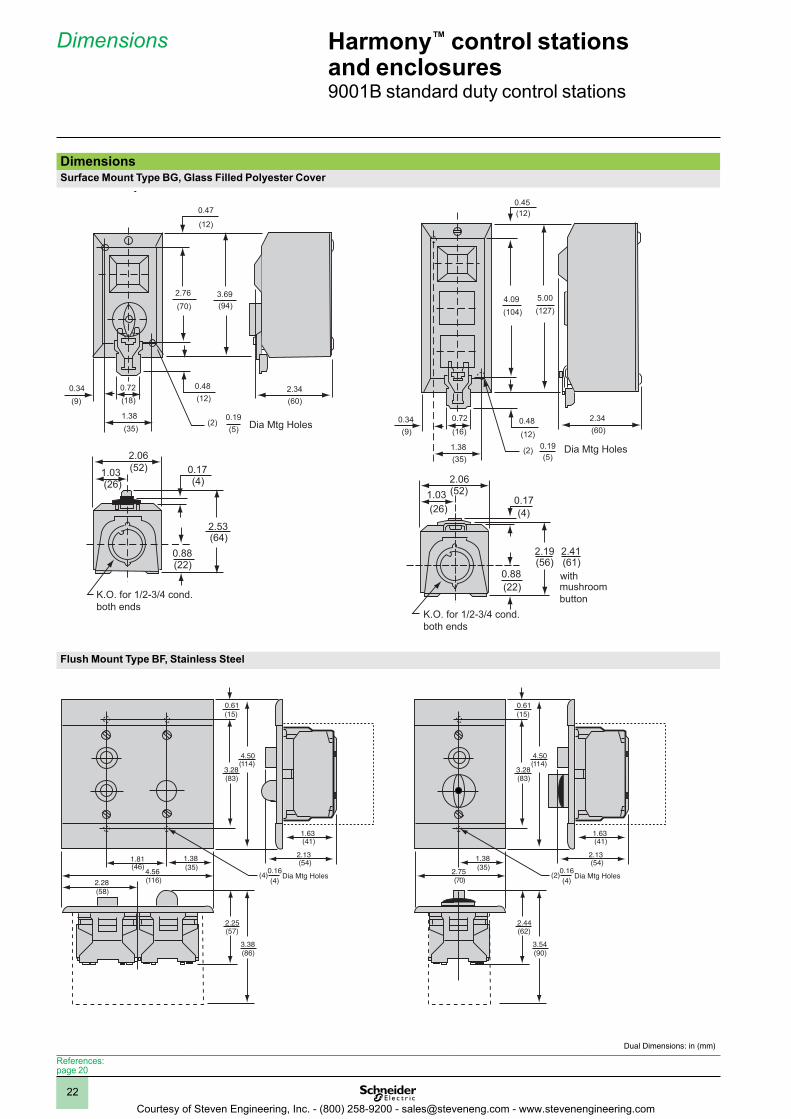
DimensionsSurface Mount Type BG, Glass Filled Polyester Cover
Flush Mount Type BF, Stainless Steel
Approximate Dimensions
Surface Mount Type BGGlass Filled Polyester Cover
0.47
(12)
2.76
(70)
3.69
(94)
0.34
(9)
0.72
(18)
1.38
(35)
0.48
(12)2.34
(60)
0.19
(5)(2) Dia Mtg Holes
2.06
(52)1.03(26)
0.17(4)
2.53(64)
0.88(22)
K.O. for 1/2-3/4 cond.
both ends
0.45
(12)
4.09
(104)
5.00
(127)
0.34
(9)
0.72
(16)
1.38
(35)
0.48
(12)
2.34
(60)
(2)0.19
(5)Dia Mtg Holes
2.06(52)
0.17
(4)
2.19(56)
2.41(61)
0.88
(22)
K.O. for 1/2-3/4 cond.
both ends
withmushroom
button
1.03
(26)
Flush Mount Type BFStainless Steel
0.61(15)
4.50(114)
3.28(83)
1.63(41)
2.13(54)
0.16(4)
(4) Dia Mtg Holes
3.38(86)
2.25(57)
1.81(46)
1.38(35)4.56
(116)2.28(58)
0.61(15)
4.50(114)
3.28(83)
1.63(41)
2.13(54)
0.16(4)
(2) Dia Mtg Holes
3.54(90)
2.44(62)
1.38(35)2.75
(70)
Harmony™ control stations and enclosures9001B standard duty control stations
Dimensions
Dual Dimensions: in (mm)
References:page 20
Approximate Dimensions
Surface Mount Type BGGlass Filled Polyester Cover
0.47
(12)
2.76
(70)
3.69
(94)
0.34
(9)
0.72
(18)
1.38
(35)
0.48
(12)2.34
(60)
0.19
(5)(2) Dia Mtg Holes
2.06
(52)1.03(26)
0.17(4)
2.53(64)
0.88(22)
K.O. for 1/2-3/4 cond.
both ends
0.45
(12)
4.09
(104)
5.00
(127)
0.34
(9)
0.72
(16)
1.38
(35)
0.48
(12)
2.34
(60)
(2)0.19
(5)Dia Mtg Holes
2.06(52)
0.17
(4)
2.19(56)
2.41(61)
0.88
(22)
K.O. for 1/2-3/4 cond.
both ends
withmushroom
button
1.03
(26)
Flush Mount Type BFStainless Steel
0.61(15)
4.50(114)
3.28(83)
1.63(41)
2.13(54)
0.16(4)
(4) Dia Mtg Holes
3.38(86)
2.25(57)
1.81(46)
1.38(35)4.56
(116)2.28(58)
0.61(15)
4.50(114)
3.28(83)
1.63(41)
2.13(54)
0.16(4)
(2) Dia Mtg Holes
3.54(90)
2.44(62)
1.38(35)2.75
(70)
Courtesy of Steven Engineering, Inc. - (800) 258-9200 - [email protected] - www.stevenengineering.com
1
2
3
4
5
6
7
8
9
10
23
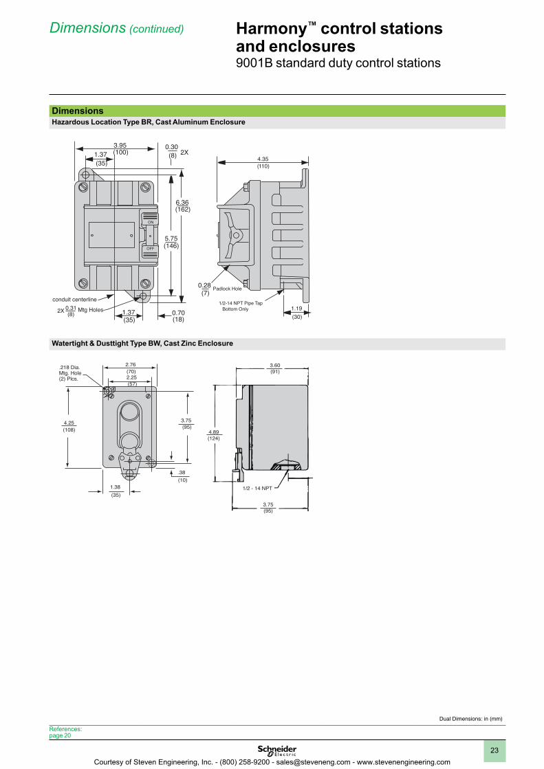
DimensionsHazardous Location Type BR, Cast Aluminum Enclosure
Watertight & Dusttight Type BW, Cast Zinc Enclosure
Hazardous LocationHazardous Location Type BRCast Aluminum Enclosure
3.95(100)1.37
(35)
0.30(8) 2X
6.36(162)
5.75(146)
ON
OFF
0.28(7)
0.70(18)
1.37(35)
conduit centerline0.31(8)2X Mtg Holes
4.35(110)
1.19(30)
1/2-14 NPT Pipe TapBottom Only
Padlock Hole
Watertight & Dusttight Type BWCast Zinc Enclosure
2.76(70)2.25(57)
3.75(95)
4.25(108)
1.38(35)
.38(10)
.218 Dia.Mtg. Hole(2) Plcs.
3.60(91)
4.89(124)
3.75(95)
1/2 - 14 NPT
Harmony™ control stations and enclosures9001B standard duty control stations
Dimensions (continued)
Dual Dimensions: in (mm)
References:page 20
Courtesy of Steven Engineering, Inc. - (800) 258-9200 - [email protected] - www.stevenengineering.com
1
2
3
4
5
6
7
8
9
10
24
Harmony™ control stations and enclosures9001KY/SKY 30 mm control stations
Components
5
4
4
4
3
3
2
1
1
1
Components
References:page 25
Dimensions:page 27
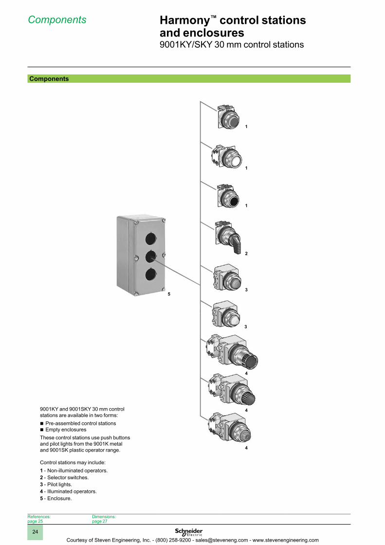
9001KY and 9001SKY 30 mm control stations are available in two forms:b Pre-assembled control stationsb Empty enclosuresThese control stations use push buttons and pilot lights from the 9001K metal and 9001SK plastic operator range.
Control stations may include:1 - Non-illuminated operators.2 - Selector switches.3 - Pilot lights.4 - Illuminated operators.5 - Enclosure.
Courtesy of Steven Engineering, Inc. - (800) 258-9200 - [email protected] - www.stevenengineering.com
1
2
3
4
5
6
7
8
9
10
25
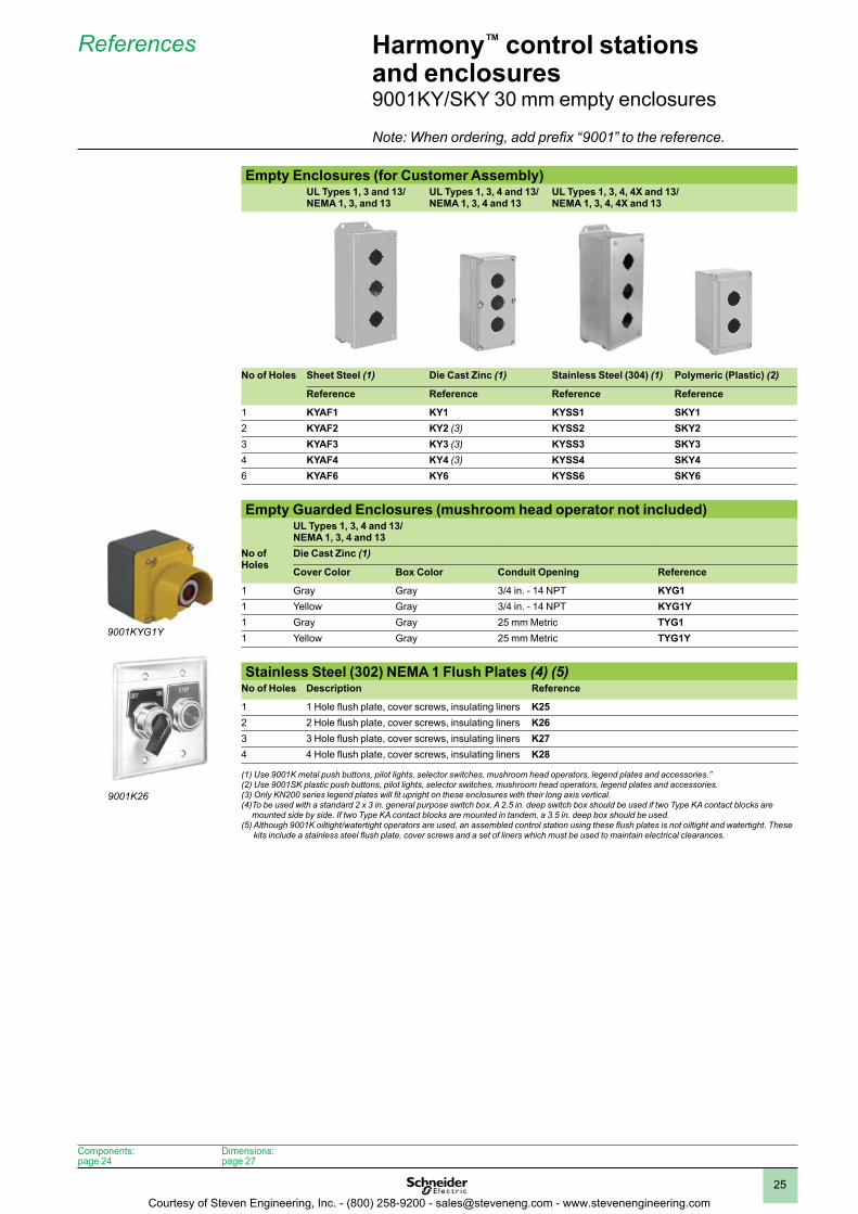
Empty Enclosures (for Customer Assembly)UL Types 1, 3 and 13/ NEMA 1, 3, and 13
UL Types 1, 3, 4 and 13/ NEMA 1, 3, 4 and 13
UL Types 1, 3, 4, 4X and 13/ NEMA 1, 3, 4, 4X and 13
No of Holes Sheet Steel (1) Die Cast Zinc (1) Stainless Steel (304) (1) Polymeric (Plastic) (2)
Reference Reference Reference Reference
1 KYAF1 KY1 KYSS1 SKY12 KYAF2 KY2 (3) KYSS2 SKY23 KYAF3 KY3 (3) KYSS3 SKY34 KYAF4 KY4 (3) KYSS4 SKY46 KYAF6 KY6 KYSS6 SKY6
Empty Guarded Enclosures (mushroom head operator not included)UL Types 1, 3, 4 and 13/ NEMA 1, 3, 4 and 13
No of Holes
Die Cast Zinc (1)
Cover Color Box Color Conduit Opening Reference
1 Gray Gray 3/4 in. - 14 NPT KYG11 Yellow Gray 3/4 in. - 14 NPT KYG1Y1 Gray Gray 25 mm Metric TYG11 Yellow Gray 25 mm Metric TYG1Y
Stainless Steel (302) NEMA 1 Flush Plates (4) (5)No of Holes Description Reference
1 1 Hole flush plate, cover screws, insulating liners K252 2 Hole flush plate, cover screws, insulating liners K263 3 Hole flush plate, cover screws, insulating liners K274 4 Hole flush plate, cover screws, insulating liners K28
(1) Use 9001K metal push buttons, pilot lights, selector switches, mushroom head operators, legend plates and accessories.”(2) Use 9001SK plastic push buttons, pilot lights, selector switches, mushroom head operators, legend plates and accessories. (3) Only KN200 series legend plates will fit upright on these enclosures with their long axis vertical. (4) To be used with a standard 2 x 3 in. general purpose switch box. A 2.5 in. deep switch box should be used if two Type KA contact blocks are
mounted side by side. If two Type KA contact blocks are mounted in tandem, a 3.5 in. deep box should be used.(5) Although 9001K oiltight/watertight operators are used, an assembled control station using these flush plates is not oiltight and watertight. These
kits include a stainless steel flush plate, cover screws and a set of liners which must be used to maintain electrical clearances.
9001K26
Harmony™ control stations and enclosures9001KY/SKY 30 mm empty enclosures
References
9001KYG1Y
Components:page 24
Dimensions:page 27
Note: When ordering, add prefix “9001” to the reference.
Courtesy of Steven Engineering, Inc. - (800) 258-9200 - [email protected] - www.stevenengineering.com
1
2
3
4
5
6
7
8
9
10
26
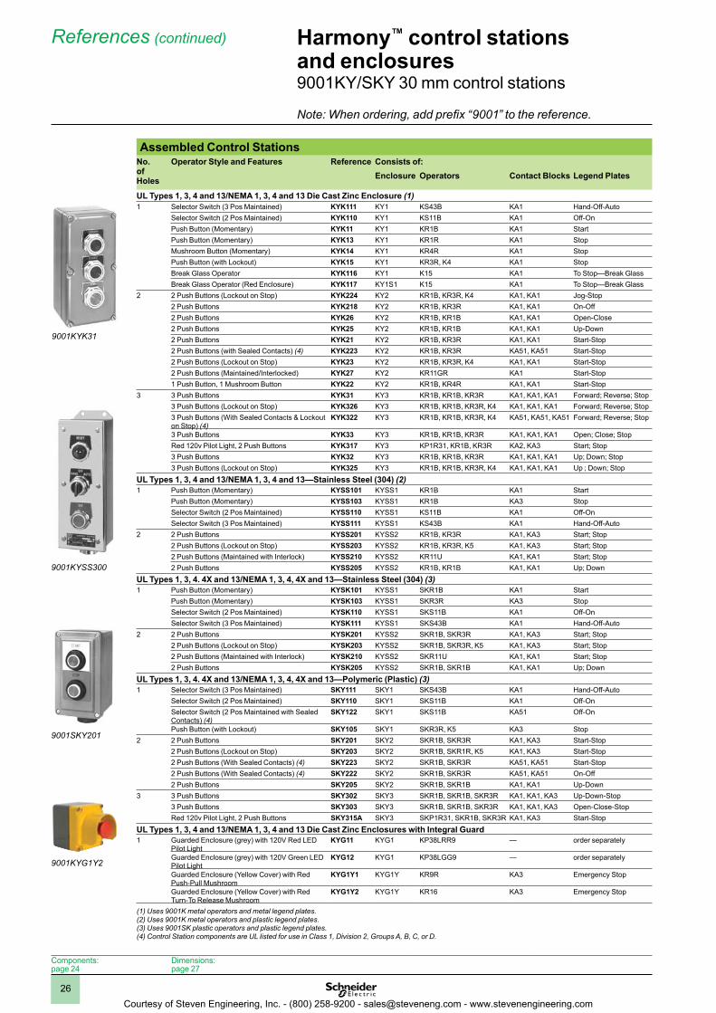
Assembled Control StationsNo . ofHoles
Operator Style and Features Reference Consists of:Enclosure Operators Contact Blocks Legend Plates
UL Types 1, 3, 4 and 13/NEMA 1, 3, 4 and 13 Die Cast Zinc Enclosure (1)1 Selector Switch (3 Pos Maintained) KYK111 KY1 KS43B KA1 Hand-Off-Auto
Selector Switch (2 Pos Maintained) KYK110 KY1 KS11B KA1 Off-OnPush Button (Momentary) KYK11 KY1 KR1B KA1 StartPush Button (Momentary) KYK13 KY1 KR1R KA1 StopMushroom Button (Momentary) KYK14 KY1 KR4R KA1 StopPush Button (with Lockout) KYK15 KY1 KR3R, K4 KA1 StopBreak Glass Operator KYK116 KY1 K15 KA1 To Stop—Break GlassBreak Glass Operator (Red Enclosure) KYK117 KY1S1 K15 KA1 To Stop—Break Glass
2 2 Push Buttons (Lockout on Stop) KYK224 KY2 KR1B, KR3R, K4 KA1, KA1 Jog-Stop2 Push Buttons KYK218 KY2 KR1B, KR3R KA1, KA1 On-Off2 Push Buttons KYK26 KY2 KR1B, KR1B KA1, KA1 Open-Close2 Push Buttons KYK25 KY2 KR1B, KR1B KA1, KA1 Up-Down2 Push Buttons KYK21 KY2 KR1B, KR3R KA1, KA1 Start-Stop2 Push Buttons (with Sealed Contacts) (4) KYK223 KY2 KR1B, KR3R KA51, KA51 Start-Stop2 Push Buttons (Lockout on Stop) KYK23 KY2 KR1B, KR3R, K4 KA1, KA1 Start-Stop2 Push Buttons (Maintained/Interlocked) KYK27 KY2 KR11GR KA1 Start-Stop1 Push Button, 1 Mushroom Button KYK22 KY2 KR1B, KR4R KA1, KA1 Start-Stop
3 3 Push Buttons KYK31 KY3 KR1B, KR1B, KR3R KA1, KA1, KA1 Forward; Reverse; Stop3 Push Buttons (Lockout on Stop) KYK326 KY3 KR1B, KR1B, KR3R, K4 KA1, KA1, KA1 Forward; Reverse; Stop3 Push Buttons (With Sealed Contacts & Lockout on Stop) (4)
KYK322 KY3 KR1B, KR1B, KR3R, K4 KA51, KA51, KA51 Forward; Reverse; Stop
3 Push Buttons KYK33 KY3 KR1B, KR1B, KR3R KA1, KA1, KA1 Open; Close; StopRed 120v Pilot Light, 2 Push Buttons KYK317 KY3 KP1R31, KR1B, KR3R KA2, KA3 Start; Stop3 Push Buttons KYK32 KY3 KR1B, KR1B, KR3R KA1, KA1, KA1 Up; Down; Stop3 Push Buttons (Lockout on Stop) KYK325 KY3 KR1B, KR1B, KR3R, K4 KA1, KA1, KA1 Up ; Down; Stop
UL Types 1, 3, 4 and 13/NEMA 1, 3, 4 and 13—Stainless Steel (304) (2)1 Push Button (Momentary) KYSS101 KYSS1 KR1B KA1 Start
Push Button (Momentary) KYSS103 KYSS1 KR1B KA3 StopSelector Switch (2 Pos Maintained) KYSS110 KYSS1 KS11B KA1 Off-OnSelector Switch (3 Pos Maintained) KYSS111 KYSS1 KS43B KA1 Hand-Off-Auto
2 2 Push Buttons KYSS201 KYSS2 KR1B, KR3R KA1, KA3 Start; Stop2 Push Buttons (Lockout on Stop) KYSS203 KYSS2 KR1B, KR3R, K5 KA1, KA3 Start; Stop2 Push Buttons (Maintained with Interlock) KYSS210 KYSS2 KR11U KA1, KA1 Start; Stop2 Push Buttons KYSS205 KYSS2 KR1B, KR1B KA1, KA1 Up; Down
UL Types 1, 3, 4 . 4X and 13/NEMA 1, 3, 4, 4X and 13—Stainless Steel (304) (3)1 Push Button (Momentary) KYSK101 KYSS1 SKR1B KA1 Start
Push Button (Momentary) KYSK103 KYSS1 SKR3R KA3 StopSelector Switch (2 Pos Maintained) KYSK110 KYSS1 SKS11B KA1 Off-OnSelector Switch (3 Pos Maintained) KYSK111 KYSS1 SKS43B KA1 Hand-Off-Auto
2 2 Push Buttons KYSK201 KYSS2 SKR1B, SKR3R KA1, KA3 Start; Stop2 Push Buttons (Lockout on Stop) KYSK203 KYSS2 SKR1B, SKR3R, K5 KA1, KA3 Start; Stop2 Push Buttons (Maintained with Interlock) KYSK210 KYSS2 SKR11U KA1, KA1 Start; Stop2 Push Buttons KYSK205 KYSS2 SKR1B, SKR1B KA1, KA1 Up; Down
UL Types 1, 3, 4 . 4X and 13/NEMA 1, 3, 4, 4X and 13—Polymeric (Plastic) (3)1 Selector Switch (3 Pos Maintained) SKY111 SKY1 SKS43B KA1 Hand-Off-Auto
Selector Switch (2 Pos Maintained) SKY110 SKY1 SKS11B KA1 Off-OnSelector Switch (2 Pos Maintained with Sealed Contacts) (4)
SKY122 SKY1 SKS11B KA51 Off-On
Push Button (with Lockout) SKY105 SKY1 SKR3R, K5 KA3 Stop2 2 Push Buttons SKY201 SKY2 SKR1B, SKR3R KA1, KA3 Start-Stop
2 Push Buttons (Lockout on Stop) SKY203 SKY2 SKR1B, SKR1R, K5 KA1, KA3 Start-Stop2 Push Buttons (With Sealed Contacts) (4) SKY223 SKY2 SKR1B, SKR3R KA51, KA51 Start-Stop2 Push Buttons (With Sealed Contacts) (4) SKY222 SKY2 SKR1B, SKR3R KA51, KA51 On-Off2 Push Buttons SKY205 SKY2 SKR1B, SKR1B KA1, KA1 Up-Down
3 3 Push Buttons SKY302 SKY3 SKR1B, SKR1B, SKR3R KA1, KA1, KA3 Up-Down-Stop3 Push Buttons SKY303 SKY3 SKR1B, SKR1B, SKR3R KA1, KA1, KA3 Open-Close-StopRed 120v Pilot Light, 2 Push Buttons SKY315A SKY3 SKP1R31, SKR1B, SKR3R KA1, KA3 Start-Stop
UL Types 1, 3, 4 and 13/NEMA 1, 3, 4 and 13 Die Cast Zinc Enclosures with Integral Guard1 Guarded Enclosure (grey) with 120V Red LED
Pilot LightKYG11 KYG1 KP38LRR9 — order separately
Guarded Enclosure (grey) with 120V Green LED Pilot Light
KYG12 KYG1 KP38LGG9 — order separately
Guarded Enclosure (Yellow Cover) with Red Push-Pull Mushroom
KYG1Y1 KYG1Y KR9R KA3 Emergency Stop
Guarded Enclosure (Yellow Cover) with Red Turn-To Release Mushroom
KYG1Y2 KYG1Y KR16 KA3 Emergency Stop
(1) Uses 9001K metal operators and metal legend plates.(2) Uses 9001K metal operators and plastic legend plates.(3) Uses 9001SK plastic operators and plastic legend plates.(4) Control Station components are UL listed for use in Class 1, Division 2, Groups A, B, C, or D.
Harmony™ control stations and enclosures9001KY/SKY 30 mm control stations
References (continued)
9001KYK31
9001KYSS300
9001SKY201
9001KYG1Y2
Components:page 24
Dimensions:page 27
Note: When ordering, add prefix “9001” to the reference.
Courtesy of Steven Engineering, Inc. - (800) 258-9200 - [email protected] - www.stevenengineering.com
1
2
3
4
5
6
7
8
9
10
27
Harmony™ control stations and enclosures9001KY/SKY 30 mm control stations
Dimensions
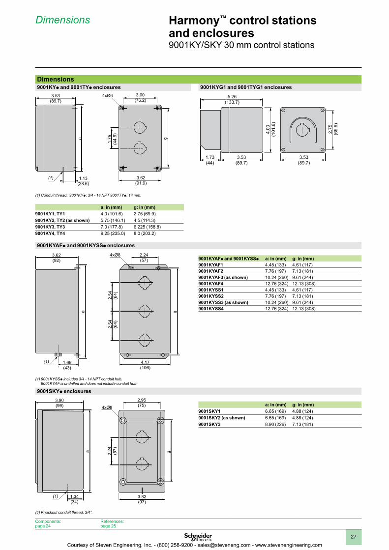
Dimensions9001KYp and 9001TYp enclosures 9001KYG1 and 9001TYG1 enclosures
3.62(91.9)
3.00(76.2)
ga
1.75
(44.
5)
3.53(89.7)
1.13(28.6)
4xØ6
(1)
(1) Conduit thread: 9001KYp: 3/4 - 14 NPT 9001TYp: 14 mm.
a: in (mm) g: in (mm)9001KY1, TY1 4.0 (101.6) 2.75 (69.9)9001KY2, TY2 (as shown) 5.75 (146.1) 4.5 (114.3)9001KY3, TY3 7.0 (177.8) 6.225 (158.8)9001KY4, TY4 9.25 (235.0) 8.0 (203.2)
9001KYAFp and 9001KYSSp enclosures
9001KYAFp and 9001KYSSp a: in (mm) g: in (mm)9001KYAF1 4.45 (133) 4.61 (117)9001KYAF2 7.76 (197) 7.13 (181)9001KYAF3 (as shown) 10.24 (260) 9.61 (244)9001KYAF4 12.76 (324) 12.13 (308)9001KYSS1 4.45 (133) 4.61 (117)9001KYSS2 7.76 (197) 7.13 (181)9001KYSS3 (as shown) 10.24 (260) 9.61 (244)9001KYSS4 12.76 (324) 12.13 (308)
(1) 9001KYSSp includes 3/4 - 14 NPT conduit hub. 9001KYAF is undrilled and does not include conduit hub.
9001SKYp enclosures
a: in (mm) g: in (mm)9001SKY1 6.65 (169) 4.88 (124)9001SKY2 (as shown) 6.65 (169) 4.88 (124)9001SKY3 8.90 (226) 7.13 (181)
(1) Knockout conduit thread: 3/4”.
4.17(106)
g
2.24(57)
3.62(92)
1.69(43)
2.54
(64)
2.54
(64)
a
4xØ8
(1)
3.82(97)
g
2.95(75)
3.90(99)
1.34(34)
a 2.24
(57)
4xØ8
(1)
Components:page 24
References:page 25
3.53
(89.7)
2.7
5
(69.9
)
3.53
(89.7)
5.26
(133.7)
1.73
(44)
4.0
0
(101.6
)
Courtesy of Steven Engineering, Inc. - (800) 258-9200 - [email protected] - www.stevenengineering.com
1
2
3
4
5
6
7
8
9
10
28
Harmony™ control stations and enclosures
Index
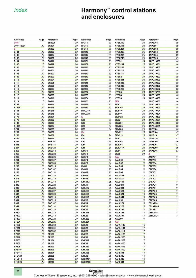
Reference Page31103110112001 20BB101 20B102 20B103 20B104 20B105 20B106 20B107 20B108 20B109 20B110 20B111 20B112 20B115 20B116 20B117 20B118 20B119 20B129 20B129R 20B161 20B162 20B175 20B176 20B189 20B189R 20B251 20B252 20B253 20B254 20B255 20B256 20B257 20B258 20B259 20B260 20B261 20B262 20B263 20B264 20B265 20B266 20B276 20B277 20B282 20B283 20B301 20B303 20B321 20B331 20B332 20B341 20B342 20BF101 20BF102 20BF107 20BF201 20BF208 20BF210 20BF211 20BF215 20BF216 20BF303 20BF305 20BF308 20BFB107 20BFB114 20BFB123 20BFB214 20BFB224 20
Reference PageBFB226 20BG101 20BG102 20BG103 20BG104 20BG107 20BG111 20BG112 20BG114 20BG201 20BG202 20BG203 20BG204 20BG205 20BG206 20BG207 20BG208 20BG209 20BG210 20BG211 20BG214 20BG215 20BG216 20BG218 20BG301 20BG302 20BG303 20BG304 20BG305 20BG307 20BG308 20BG316 20BGB107 20BGB114 20BGB123 20BGB214 20BGB224 20BGB226 20BGB307 20BGB309 20BGB315 20BGC107 20BGC114 20BGC123 20BGC214 20BGC218 20BGC224 20BGC226 20BGC307 20BGC309 20BGC313 20BGC315 20BOC107 20BOC114 20BOC123 20BOC214 20BOC218 20BOC224 20BOC226 20BOC360 20BOC361 20BOC362 20BR101 20BR103 20BR104 20BR107 20BR202 20BR203 20BR204 20BR205 20BR208 20BR214 20
Reference PageBR215 20BR216 20BR218 20BW146 20BW147 20BW148 20BW151 20BW159 20BW240 20BW241 20BW242 20BW243 20BW244 20BW245 20BW246 20BW250 20BW252 20BW253 20BW254 20BW255 20BW256 20BW260 20BWD219 20BWD220 20KK25 24K26 24K27 24K28 24KYKY1 24KY2 24KY3 24KY4 24KY6 24KYAF1 24KYAF2 24KYAF3 24KYAF4 24KYAF6 24KYG1 24KYG11 25KYG12 25KYG1Y 24KYG1Y1 25KYG1Y2 25KYK11 25KYK110 25KYK111 25KYK116 25KYK117 25KYK13 25KYK14 25KYK15 25KYK21 25KYK218 25KYK22 25KYK223 25KYK224 25KYK23 25KYK25 25KYK26 25KYK27 25KYK31 25KYK317 25KYK32 25KYK322 25KYK325 25KYK326 25KYK33 25KYSK101 25KYSK103 25
Reference PageKYSK110 25KYSK111 25KYSK201 25KYSK203 25KYSK205 25KYSK210 25KYSS1 24KYSS101 25KYSS103 25KYSS110 25KYSS111 25KYSS2 24KYSS201 25KYSS203 25KYSS205 25KYSS210 25KYSS3 24KYSS4 24KYSS6 24SKYSKY1 24SKY105 25SKY110 25SKY111 25SKY122 25SKY2 24SKY201 25SKY203 25SKY205 25SKY222 25SKY223 25SKY3 24SKY302 25SKY303 25SKY315A 25SKY4 24SKY6 24XALXALD01 11XALD02 11XALD03 11XALD04 11XALD05 11XALD101 10XALD111 10XALD164 10XALD211 10XALD221 10XALD311 10XALD321 10XALD341 10XALK01 11XALK174 10XALK178 10XALK184 10XALK188 10XALK194 10XALZ09 11XAPXAPA1100 16XAPA1104 17XAPA1110 17XAPA1120 17XAPA2100 16XAPA2108 17XAPA3100 16XAPA3116 17XAPA4100 16XAPE301 19XAPE302 19XAPE303 19XAPE304 19
Reference PageXAPE305 19XAPE901 19XAPE902 19XAPE903 19XAPE904 19XAPE905 19XAPG19100 18XAPG19201 18XAPG19400 18XAPG19501 18XAPG19702 18XAPG19802 18XAPG29100 18XAPG29202 18XAPG29400 18XAPG29502 18XAPG29703 18XAPG29803 18XAPG39100 18XAPG39203 18XAPG39400 18XAPG39503 18XAPG39704 18XAPG39804 18XAPG49400 18XAPG49504 18XAPG59400 18XAPG59505 18XAPZ100 16XAPZ104 17XAPZ110 17XAPZ120 17XAPZ200 16XAPZ208 17XAPZ300 16XAPZ316 17ZZALVB1 11ZALVB3 11ZALVB4 11ZALVB5 11ZALVB6 11ZALVG1 11ZALVG3 11ZALVG4 11ZALVG5 11ZALVG6 11ZALVM1 11ZALVM3 11ZALVM4 11ZALVM5 11ZALVM6 11ZB5AZ901 11ZB5AZ905 11ZB5SZ3 11ZENL1111 11ZENL1121 11
Courtesy of Steven Engineering, Inc. - (800) 258-9200 - [email protected] - www.stevenengineering.com

Courtesy of Steven Engineering, Inc. - (800) 258-9200 - [email protected] - www.stevenengineering.com

The information and dimensions in this catalog are provided for the convenience of our customers. While this information is believed to be accurate, Schneider Electric reserves the right to make updates and changes without prior notification and assumes no liability for any errors or omissions.
Harmony, Schneider Electric and logo are trademarks or registered trademarks of Schneider Electric or its affiliates in the United States and other countries. Other trademarks used herein are the property of their respective owners.
Design: Schneider ElectricPhotos: Schneider Electric
© 2011 Schneider Electric. All rights reserved. 05/20119001CT1104
http://www.schneider-electric.us/Schneider Electric USA, Inc .8001 Knightdale Blvd. Knightdale, NC 27545
USA Customer Care CenterTel: 888-778-2733
Schneider Electric Canada5985 McLaughlin Rd.Missassauga, Ontario, Canada L5R 1B8
Canada Customer Care CenterTel: 800-565-6699
Courtesy of Steven Engineering, Inc. - (800) 258-9200 - [email protected] - www.stevenengineering.com