Schiedel Gas Flue Block System
12
The Schiedel Gas Flue Block System provides the ideal solution to build a safe and high performance flue for gas appliances. Schiedel Gas Flue Block System SEPTEMBER 2005
Transcript of Schiedel Gas Flue Block System

The Schiedel Gas Flue Block System provides
the ideal solution to build a safe and high
performance flue for gas appliances.
Schiedel Gas FlueBlock System
SEPTEMBER 2005
Schiedel Gas Flue Block System
Introduction
The Schiedel Gas Flue Block System is a high quality factorymade gas flue block system which provides the ideal solutionto build a safe and high performance flue for gas appliances.
The standard blocks have a height to match brick or blockworkand can be built into traditional cavity wall construction, whichsaves on cost and space.
Schiedel gas flue blocks feature a special rebated jointingarrangement which ensures ease of installation and a positiveseal by using the cartridge applied jointing compound. Therebated joint minimises the risk of jointing compound extrudinginto the flueway.
Available with a comprehensive range of fittings the system gives Architects and Builders an almost limitless choice ofeconomical and efficient solutions for building gas flues.
Approvals and Specifications
The system meets the relevant requirements of Building Regulations and has been successfully tested to BS EN 1858 with the given designation of T250, N2, D, 1, O(50).
Installation and Use
In the UK the system must be installed in line with therecommendations of British Standards BS 5440: Part 1 Covering the installation of flues for gas appliances.
For installation in the Republic of Ireland the flues must beinstalled and used as the instruction given in this brochureand to the recommendations of IS 813:2002.
The maximum overall height of the flue must not exceed 12 metres and can only be used with gas appliances having a rated input not exceeding 60 kW.
The system can be used with standard gas burning fires andconvector heaters in accordance with BS 5871: Part 1. It can also be used with many types of inset live fuel effect gas fire(ILFE’s) that imitate solid fuel open fires, providing the appliancemanufacturer’s instructions allow this and the fire has beenapproved for use with gas flue blocks.
The flues can be terminated above the roof or at a gas ridge vent terminal, in which case the twin wall gas flue is used from the flue block system in the roof space to a ridge tile adaptor or GO terminal.
The choice of precast recess units provides a low cost answerfor accommodating a gas appliance with the flue blocks.
The Schiedel gas flue blocks feature:
slim space saving design
positive rebated joints
comprehensive choice of fittings
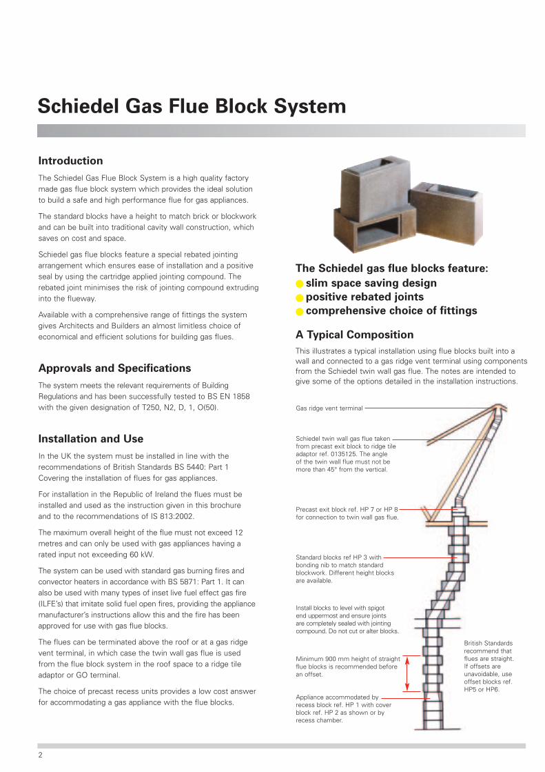
A Typical Composition
This illustrates a typical installation using flue blocks built into awall and connected to a gas ridge vent terminal using componentsfrom the Schiedel twin wall gas flue. The notes are intended togive some of the options detailed in the installation instructions.
Appliance accommodated byrecess block ref. HP 1 with coverblock ref. HP 2 as shown or byrecess chamber.
Schiedel twin wall gas flue takenfrom precast exit block to ridge tileadaptor ref. 0135125. The angleof the twin wall flue must not bemore than 45° from the vertical.
Gas ridge vent terminal
Install blocks to level with spigotend uppermost and ensure jointsare completely sealed with jointingcompound. Do not cut or alter blocks.
British Standardsrecommend thatflues are straight.If offsets areunavoidable, useoffset blocks ref.HP5 or HP6.
Precast exit block ref. HP 7 or HP 8for connection to twin wall gas flue.
Standard blocks ref HP 3 withbonding nib to match standardblockwork. Different height blocksare available.
Minimum 900 mm height of straightflue blocks is recommended beforean offset.
2

Plan of standard block.Aspect ratio 1:2.56
HP1
Recess block. Used to formbasic appliance recess.
HP2
Cover block. Used to gatherin opening above HP1.
HP3
Standard block 222mmhigh with nib.
HP3 (72)72mm high coursingblock with nib.
HP3 (112)112mm high coursingblock with nib.
HP3 (147)147mm high coursingblock with nib.
HP4
222mm high blockwithout nib.
HP4 (72)72mm high coursingblock without nib.
HP4 (112)112mm high coursingblock without nib.
HP4 (147)147mm high coursingblock without nib.
HP5
Side offset block giving120mm offset.
HP6
Back offset block giving70mm offset.
HPDB
High Density Block. Used behindrecess units in party walls.
HP7
Vertical exit block for connectionto GF twin wall flue.
HP8
Angled exit block for connectionto GF twin wall flue. Use invertedfor connection of boiler flue pipe.
HP9
Reverse rebate block with spigoton both ends. Used with invertedHP7 or HP8.
HP10
Corbel block. Used to carry brickworkin front of flue when building a stackabove roof line.
HP11
Lintel block. Used to carry single skinof brick/block work in front of flue tocreate chimney breast.
HP42
Deep recess cover block.
HP41
Deep recess block
270490
222
The Standard Range of Components
Damp proofing materials
DPCMDPCM mat with dpc bonded ontoinsulation. Used in cavity wall behindflue to provide vertical dpc.
Jointing materialsFJC Flue Jointing Compound 300ml cartridge.
3
DPMDPM
DPM
DPM
DPM
HP41
HP41
HP41
HP42
OR
OR
HP3
HP1
HP1
HP1
HP2
HP3
HP3
HP3
HP3
HP3
HP3
HP3
HP3
HP3
HP3
HP3
HP3
HP8
HP3
HP3
HP3
HP3
HP3
HP3
DPM
DPM
225
495 405
325420
2400
2400
1208125 Adjustable Straight 50-450mm
1205125 450mm Straight
1202125 900mm Straight
1218125 Adjustable Bend
1243125 Connector
1218125Adjustable Bend
0135125 RidgeTile Adaptor
DPMDPM
DPM
DPMDPM
DPM
DPM
OR
OR
HP42
HP41
HP41
HP41
HP8
HP5
HP5
HP5
HP5
HP5
HP5
HP5
HP5
HP5
HP3
HP3
HP3
HP3
HP3
HP3
HP3
HP3
HP2
HP1
HP1
HP1
HP3
HP5
DPM
2400
2400
420 325
405495
OFFSET1200
1208125 Adjustable Straight 50-450mm
1205125 450mm Straight
1202125 900mm Straight
1218125 Adjustable Bend
1243125 Connector
1218125Adjustable Bend
0135125 RidgeTile Adaptor
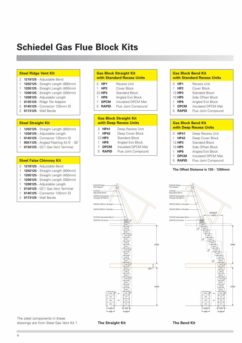
Schiedel Gas Flue Block Kits
Gas Block Straight Kit
with Standard Recess Units
3 HP1 Recess Unit1 HP2 Cover Block23 HP3 Standard Block1 HP8 Angled Exit Block7 DPCM Insulated DPCM Mat5 RAPID Flue Joint Compound
The Straight Kit The Bend Kit
Steel Ridge Vent Kit
2 1218125 - Adjustable Bend1 1202125 - Straight Length (900mm)1 1205125 - Straight Length (450mm)1 1206125 - Straight Length (300mm)1 1208125 - Adjustable Length1 0135125 - Ridge Tile Adaptor2 0145125 - Connector 125mm ID2 0173125 - Wall Bands
Steel Straight Kit
1 1202125 - Straight Length (900mm)1 1208125 - Adjustable Length1 0145125 - Connector 125mm ID1 9551125 - Angled Flashing Kit 5˚ - 30˚1 0130125 - GC1 Gas Vent Terminal
Steel False Chimney Kit
2 1218125 - Adjustable Bend1 1202125 - Straight Length (900mm)1 1205125 - Straight Length (450mm)1 1206125 - Straight Length (300mm)1 1208125 - Adjustable Length1 0130125 - GC1 Gas Vent Terminal1 0145125 - Connector 125mm ID2 0173125 - Wall Bands
Gas Block Straight Kit
with Deep Recess Units
3 HP41 Deep Recess Unit1 HP42 Deep Cover Block23 HP3 Standard Block1 HP8 Angled Exit Block7 DPCM Insulated DPCM Mat5 RAPID Flue Joint Compound
Gas Block Bend Kit
with Standard Recess Units
3 HP1 Recess Unit1 HP2 Cover Block13 HP3 Standard Block10 HP5 Side Offset Block1 HP8 Angled Exit Block7 DPCM Insulated DPCM Mat5 RAPID Flue Joint Compound
Gas Block Bend Kit
with Deep Recess Units
3 HP41 Deep Recess Unit1 HP42 Deep Cover Block13 HP3 Standard Block10 HP5 Side Offset Block1 HP8 Angled Exit Block7 DPCM Insulated DPCM Mat5 RAPID Flue Joint Compound
The Offset Distance is 720 - 1200mm
The steel components in thesedrawings are from Steel Gas Vent Kit 1
4

Recess Units
Typical Recess InstallationsThese units offer a choice of recess openings to suit differentgas fired appliances, which can be used with the Schiedel gasflue block range.
The recesses will accept most types of standard radiant gas fireswhich must be installed to BS 5871 : Part 1. Many inset live fueleffect gas fires imitating a solid fuel open fire can also be fitted,but must be approved for this type of application and be installedto BS 5871 : Part 2.
Standard Recess Arrangement
This is the most popular space saving layout used with a standardradiant gas fire and the HP gas flue block system built into the innerleaf of the cavity wall. A decorative cladding of 100 mm brickworkcan be built in front of the flue blocks using a lintel block HP11.
Inset live fuel effect gas fires which imitate an open fire can be fittedin this recess, providing they are approved for use with gasflue blocks. The appliance manufactures installation instructionsmust be followed and often require fitting of a spacer frame in frontof the recess to give sufficient clearance at the back of the appliance.
Deep Recess Unit
675 mm high x 420 mm wide x 220 mm deep.
Consists of
HP41 - lower unitsUnits to be laid to level with 10 mm thick mortar joint.
Connected to the HP42 cover block.
Standard Starter Block Recess
Internal recess opening675 mm high x 325 mm wide x 115 mm deep.
Consists of
3 no. recess blocks HP1 and a cover block HP2 providing agather above the recess opening with outlet for connectionto the HP flue block system.
Units to be laid to level with 3 mm thick mortar joint.
Deep Recess Arrangement
This is commonly used with inset live fuel effect gas fires and isalso suitable for use with standard gas fires.
When built into a wall with the Schiedel gas flue block system theprojecting recess units can be accommodated by fitting a deepbacked surround as shown in the illustration. Alternatively a falsechimney breast can be built using plasterboard on stud framework.
5

Schiedel Twin Wall Flue
The Range of Components
Nominal flue diameter - 125mm (5”)Nominal external diameter - 152mm (6”)
Flue block adaptor
0145125 - Connector with 125mm spigotfor connecting to appliance orexit block.
Adjustable bend (elbow)
1218125 - Adjustable bend giving angleof 0˚-90˚
Straight lengths
1207125 - Effective length 150mm1206125 - Effective length 300mm1205125 - Effective length 450mm1202125 - Effective length 900mm1201125 - Effective length 1500mm1208125 - Adjustable length
50mm to 450mm
Wall band
0173125 - Wall band giving 50mmclearance from wall
Terminal
0130125 - GC1 gas vent terminal
Flashing
95510125 - Angled flashing kit 5˚ - 45˚
Ridge tile adaptor
0135125 - Fabricated aluminium ridgetile adaptor
Fig. 1
Twist lock connection
6
B
A
Introduction
The Schiedel Twin Wall Flue is a high quality factory made twinwall gas vent system, with a range of components that simplytwist lock together for fast and economical installation. It offers anideal solution for installing a new flue system for gas appliancesand an efficient method for connecting the Schiedel gas flue blocksystem to an external terminal.
Approvals and Specifications
The Twin Wall Flue is approved to BS715 and has been tested and approved to EN 1856-1:2003-06 and carries the designation T250 N1 D VM L11040 050 under certificate 0036 CPD 9195 013.
It is also included in the British Gas list of certified flues andterminals. The product is manufactured under the strict guidanceof BSEN ISO 9001.
The flue gas carrying components have a 12.5mm air gapbetween an aluminium liner (1200 H14) and an aluzink case (ZAZ).The twist locking spigot and sockets are manufactured fromaluzink (ZAZ). All vertical seams are lock-formed and the product is manufactured so as to allow thermal expansion of the liner.
Installation and Use
The system must be installed and maintained in accordance withthe manufacturer’s instructions and in accordance with BS 5440:Part 1 and Doc J of the Building Regulations.
Schiedel Twin Wall Flue is suitable for rated appliances with aninput not exceeding 60kW.
Appliances connected to Schiedel Twin Wall Flue must beinstalled in accordance with the relevant National Standards and applicable Building Regulations.
Method of Assembly
Fig. 2
The height of the adjustablelength is achieved as shown.
150
610 610
35678
182
200
110

Installation InstructionsThe Schiedel Gas Flue system can be used as an independentflue to serve gas fired heating appliances requiring a 125 mm fluediameter and also to connect the Schiedel gas flue block systemto a suitable termination.
1. Preparation
Any connection of flue components to an appliance not connectedto gas can be carried out by a competent person. Connection toan appliance already connected to gas must be carried out by aregistered Corgi installer.
2. Location of the flue
The flue can be installed internally or externally but external runsexceeding 3m require a stainless steel insulated flue (SchiedelRite-Vent K Vent). K-Vent is compatible with the Schiedel twin wall.British Standards recommend that the flue should be installedvertically and that bends should be kept to a minimum. Wherebends are used, the angle should not exceed 45° from the vertical.
3. Termination
Ensure that the flue is terminated in accordance with BuildingRegulations and BS 5440: Part 1. For roof ridge termination usethe ridge tile adaptor which must be connected to a suitablegas ridge vent terminal. See details given in gas flue block installation instructions.
4. Clearance to combustible materials
A minimum clearance of 50mm must be kept between the caseand any combustible materials.
5. Support and connections
Fit the appliance connector to appliance spigot and seal using firerope and fire cement or a suitable high temperature silicone.
When connecting to a flue block, use part no. 0145125 and sealappropriately as explained in connecting to appliance. Lateralsupport should be provided by fitting wall bands at a maximum of 3m intervals.
An adjustable pipe used with a pipe section above the applianceallows easy removal for access to appliance maintenance. Note: an adjustable must not be fitted above a bend and a wallband must be used above the adjustable as it is not load-bearing. (See Fig. 2 on the opposite page)
6. Jointing the flue components
Pipes, bends, tees and flue gas carrying components are joinedtogether by a simple twist lock bayonet system. The externallocking collars should be uppermost and pointing in the directionof the terminal as indicated by the arrow on the product label. (See Fig. 1 on the opposite page)
7. Roof penetration and flashing
Secure the flue with a wall band below the point where it passesthrough the roof. Seal all joints with silicone to prevent ingress of water.
8. Use and maintenance
Schiedel twin wall is only suitable for gas appliances not exceeding60kW. Do not use with solid fuel or oil appliances, or appliancesthat require a larger flue size.
The flue should be cleaned at least annually to ensure that nodeposits or condensates accumulate and cause restrictions.Cleaning should be carried out by a registered NACS chimney sweep.
Typical Vertical Internal Flue Arrangement
Location of outlet
7
Gas TerminalRef. 0130125
Flashing95510125
Location of outlet
Above the highest point of an intersection with the roof
From a vertical structure to the side of the terminal
Above a vertical structure which is less than 750mm (pressure jet burner) or
2300mm (vapourising burner) horizontally from the side of the terminal
From a ridge terminal to a vertical structure on the roof
M
N
O
P
600mm
750mm
600mm
1500mm
1000mm
2300mm
1000mm
should notbe used
Application:pressurejet burner
Application:vapourising
burner
Schiedel Gas Flue Block System
Installation Instructions
Introduction
The product installation and technical details must be followedtogether with the recommendations of the Building Regulationsand British Standards BS 5440.
1. Preparation and handling
Ensure that the correct components have been chosen and areready for installation to commence.
Store components safely on flat ground and cover to protectagainst damage and adverse weather conditions. Componentsthat are damaged, altered or cut must not be used.
Safe working access and platforms must be provided in accordance with Health and Safety regulations which mustbe followed at all times.
2. Location and layout of the flue
As recommended by British Standards the flue should take themost direct practicable route. Inclined (offset) runs should beavoided as a totally vertical flue is preferred. The equivalent flueheight for the proposed flue arrangement must be checked inaccordance with Appendix A of BS 5440 : Part 1.
Position the flue so that it does not affect or conflict withstructural elements such as loadbearing lintels, floor androof timbers. Combustible material must remain at least 50mmfrom the outside of the flue blocks. Where the combustible isstructural (ie floor joists or roof timbers) this gap should befilled with non-combustible insulation.
Ensure that the joints and courses of the brick/blockwork wallsare constructed to a good standard and align with the bondingflue blocks. Terminate the flue at the correct height and locationas required by Building Regulations.
3. Appliance installation
Check that the chosen appliance is suitable for the fluearrangement in accordance with the appliance manufacturersinstallation instructions and recommendations of the relevant partof BS 5871. Installation and connection of the appliance must becarried out by a CORGI registered installer.
The HP system can also be used with many types of inset livefuel effect gas fires that imitate a solid fuel open fire, providingthe fire has been tested and approved for use with gas flue blocksystems. Install the appropriate recess to suit the appliance, somemanufacturers specify that a spacer frame is fitted with theappliance to increase the depth of the recess opening.
4. Appliance recess and connection
The flue installation must start with a recess arrangement to suitthe appliance or an angled exit block HP8 supported in the wall tosuit a boiler type arrangement. A suitable hearth must be providedfor the appliance and its depth must be taken into consideration inrelation to the finished height of the recess opening.
The following illustrations show typical arrangements with the flueblocks built flush to the front of the inner leaf of the cavity wall.The flue blocks may also be built partially into the wall, in whichcase the recess arrangement must be positioned as required.
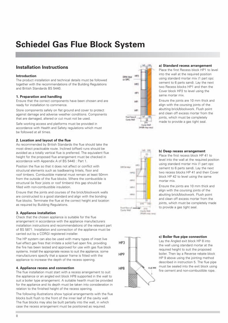
a) Standard recess arrangement
Place the first Recess block HP1 to levelinto the wall at the required positionusing standard mortar mix (1 part opccement to 6 parts sand). Lay the nexttwo Recess blocks HP1 and then theCover block HP2 to level using thesame mortar mix.
Ensure the joints are 10 mm thick andalign with the coursing joints of theabutting brick/blockwork. Flush pointand clean off excess mortar from thejoints, which must be completelymade to provide a gas tight seal.
b) Deep recess arrangement
Place the first recess block HP 41 tolevel into the wall at the required positionusing standard mortar mix (1 part opccement to 6 parts sand). Lay the nexttwo recess blocks HP 41 and then Coverblock HP 42 to level using the samemortar mix.
Ensure the joints are 10 mm thick andalign with the coursing joints of theabutting brick/blockwork. Flush pointand clean off excess mortar from thejoints, which must be completely madeto provide a gas tight seal.
c) Boiler flue pipe connection
Lay the Angled exit block HP 8 intothe wall using standard mortar at therequired height to suit the proposedboiler. Then lay a Reverse rebate blockHP 9 above using the jointing methoddescribed in instruction 5. The flue pipemust be sealed into the exit block usingfire cement and non-combustible rope.
8

5. Jointing the flue blocks
ALL THE FLUE BLOCKS MUST BE LAID SPIGOT END UP WITHA 3mm THICK JOINT THAT IS COMPLETE AND GAS TIGHT.
The most convenient method of jointing is to use cartridges ofready mixed high temperature mortar applied with a cartridge gun.The nozzle must be used and cut 35 mm from the end to give a8mm bead. Ensure the upper face of the block is dry and clearof debris.
Apply a continuous 8 mm thick bead of the compound ontothe upper face of the block against the shoulder of the spigot.Do not allow any compound to go onto the top of the spigot.
8. Offsets
Both British Standards and British Gas recommend that verticalflues are preferred. Offsets if unavoidable should be kept to aminimum using the appropriate offset blocks installed and jointedin the same way as the standard flue blocks. A minimum 900mmheight of straight blocks is recommended before an offset inthe flue.
Bed the next block with the socket end facing down into thejointing compound and make a complete seal with a 3mmthick joint. Flush point the joint on the outside of the blocksand remove any excess mortar in the flueway.
6. Protecting the flue on site
It is good practice at the end of each day or during heavy rainto cover laid flue blocks to prevent joints being washed out.
7. Installing the flue blocks
Blocks with bonding nibs must be built into the surrounding masonryand laid with the nib on alternative sides as each course is built.Bonding the flue blocks into the wall should start as soon as ispractical above the recess or appliance connection arrangement.The joints in the surrounding masonry must align with the jointsof the flue blocks.
If adjustment in the coursing of the flue blocks is required use theappropriate HP coursing blocks. Do not alter or cut any flue blocksto make on-site adjustments.
Typical side offset arrangement
9. Building the flue blocks into a wall
The flue blocks can be built flush or partially into solid or cavitywall construction. The following illustrations show theconstruction requirements.
a) Installation into external cavity wall.
Typical back offset arrangement
If the external wall is in an exposed position or the flue blocksproject into or reduce the cavity, a vertical damp proof membranemust be installed in the cavity behind the flue blocks as perinstruction 10.
The provision of a vertical dpm is not required if the full depth ofthe cavity is maintained ie. where the flue is built into an innerleaf of the same or greater thickness as the flue blocks.
9

Schiedel Gas Flue Block System
b) Installation into party wall
When recess units and flue blocks are built into a party wallcompliance with Document E of the Building Regulations can besatisfied by the installation being carried out in accordance withthe Robust Details. You will need to install the high-density blocksbehind the recess units, an 8mm render coat with scratch finishand 12.5mm of plasterboard to both faces of the wall.
Please see diagrams 1 and 2.
Ensure that the DPM and cavity trays provide complete protectionfor the full length of the flue block arrangement and are not tornor punctured. If necessary suitable wall ties can be used to securethe mats in place.
Typical installation of DPCM mats
To prevent water penetration into thebuilding a suitable cavity tray must beinstalled directly above the top mat andany other horizontal surfaces of the matwhich are exposed on their upper edge.
The cavity wall tray must project at least100 mm beyond the edge of the mat andincorporate stop ends. The DPM flangeat the top of the mat must be securedup against the inner leaf directly belowthe cavity tray.
11. Termination
The gas flue block system can be terminated as follows:
a) Ridge vent arrangement
Finish the flue blocks in the roof space with an HP 7 or HP 8 exitblock. Convert to the twin wall flue by sealing the connector1243125 into the exit block with fire cement and non-combustiblerope. Extend the twin wall flue to a ridge tile adaptor 0135125and connect to an approved gas ridge vent terminal.
At all horizontal joints the DPM flange at thetop of the lower mat must be dressed upagainst the inner leaf of the cavity wall withthe bottom flange of the upper mat totallyoverlapping the top of the lower mat againstthe face of the external leaf of the cavity wall.
Inner leaf/flue blocks
External leaf
Cavity traywith stop ends
HP8Top flange ofDPM dressedin below cavitytray dpc.
Inner leaf/flue blocks
External leaf
Top flange of lower mattucked up behind mat above.
Bottom flange of DPM on uppermat dressed in front of lower mat.
10. Vertical damp proof course in external cavity
wall construction
When the flue blocks project into or reduce the cavity in an externalcavity wall construction the installation of a vertical damp proofmembrane in the cavity behind the flue blocks is required.
The most convenient method is to use the DPCM mats. Thesemust be placed with the damp proof membrane (DPM) againstthe external leaf of the cavity wall, ensuring the DPM oversailsall edges of the flue blocks by at least 50 mm and is securedagainst the external leaf.
The bottom flange of the DPM on the first mat must be dresseddown against the external leaf of the cavity wall. When placingthe mats on top of each other ensure they abut tightly withoutany gaps.
1) Plan of Recess Units
2) Plan above Recess Units
10

Typical detail of termination at Gas Ridge Vent Terminal
The flue arrangement must befinished off with a concrete cappingor corbelled brickwork and mortarflaunching with a dpc to preventwater penetration.
Standard flashings and dpc’s mustalso be provided at the point wherethe flue and masonry claddingpasses through the roof.
The flue must terminate at thecorrect height in accordance withBuilding Regulations shown in theinstallation details.
c) Using Schiedel twin wall gas flue
The twin wall gas flue can be used from the exit block connectionto take the flue through the roof. Refer to the Schiedel installationinstructions and minimum termination heights.
The twin wall flue pipe must be supported and installed at anangle not more than 45° from the vertical into the ridge tileadaptor 0135125 to which an approved gas ridge vent terminalmust be fitted.
b) Chimney stack arrangement
If a traditional chimney stack is required the Corbel block HP10and a suitable prestressed lintel can be used just below the roofline to support 100 mm thick masonry in front of the flue blocks.The masonry on the remaining three sides is to be supportedon the surrounding walls. The flue is continued using HP 4 flueblocks and is finished with a Vertical exit block HP 7 onto whichan approved Gas terminal is to be sealed with mortar flaunching.
Any gaps between the plasterboard or masonry facing and recessarrangement must be completely sealed around the recessopening. At first floor level and above plaster or render finishescan be applied onto the flue blocks.
13. Checking and testing the flue
British Standards require that all flues are checked and smoketested during construction to ensure the flue components andparticularly all joints are installed correctly.
The flue block installation should be smoke tested at each floorlevel during construction and once the last block has been fitted(ie. an exit block). A further smoke test should be made once theterminal is fitted and include testing of any twin wall flue if usedas part of the flue arrangement.
a) Smoke test procedure
The following is based on the method described in BS 5440 Part 1 : 2000.Pre-heat the flue for 2 to 5 minutes using a blow torch. With verywet or cold flues a longer warming up time may be neededto establish a draw in the flue.Place a flue testing smoke pellet on a brick or similar in theopening at the base of the flue.Ignite the pellet and when it starts smoking place a board orplate over the opening leaving a gap of 25 mm at the bottomto allow air to enter the flue.Check that the smoke is exiting freely from the correct terminaland examine the full length of the flue for any leakage of smoke.If possible check wall cavities at the back of the flue or openingsaround the windows.If smoke is seen investigate to identify the point of leakage andcarry out remedial work to correct.After completing the remedial work repeat the testing procedureuntil no leakage is apparent.Follow the smoke pellet manufacturers safety instructions.
b) Appliance spillage test
Once the appliance is fitted a CORGI registered installer or similarqualified person must carry out a spillage test in accordance withthe appliance manufacturers instructions and British Standardrecommendations.
Alternatively masonry cladding canbe built in front of the flue blocksto create a chimney breast feature.The Lintel block HP 11 can be useddirectly in front of the Cover block HP2 of the standard recess arrangement.
12. Internal finishes
The flue blocks directly above the appliance should not be plasteredas unsightly surface cracking may occur whilst using the appliance.It is recommended that a plasterboard facing is placed in front of theflue blocks with a small air gap in between. This can be achievedusing stud work or plaster board on dabs which must not be placedon the front of the flue blocks.
11

The full range of Schiedel products
14 Haviland RoadFerndown Industrial Estate.Wimborne, Dorset BH21 7RFTel: 01202 861650Fax: 01202 [email protected]
Shawell Plant, Gibbet LaneShawell, Lutterworth,Leicestershire LE17 6ABTel: 01788 860930Fax: 01788 [email protected]
Carrickmacross Co. Monaghan,IrelandTel: 042 9661766Fax: 042 [email protected]
Washingbay RoadCoalisland, Co. TyroneBT71 4NDTel: 028 8774 0436Fax: 028 8774 [email protected]
Ceramic and Concrete Products
Schiedel Chimney Systems has a competitive range of clay flue liners, chimney pots and ridge tiles.
Schiedel is the only company in the UK and Ireland to have the CE Mark on its flue liners.
Also available are the Gas Flue Block system and a range of concrete liners.
Click on www.schiedel.co.uk or www.schiedel.ie for a full
range of chimney systems and accessories available from Schiedel.
Schiedel Chimney Systems
The Schiedel Swift chimney system combines speed and ease of assembly with consistent quality.
Suitable for Timber Frame, Steel Frame and Masonry construction.
Modular units for easy assembly on site. An 8 metre internal chimney can be constructed fromground floor to chimney pot in 5 hours.
Suitable for all fuels - gas, oil, wood and solid fuels.
Everything you need. All the components required to construct the chimney from the groundfloor to the chimney pot are supplied on one or two pallets.
Pumice Systems
The Schiedel ISOKERN chimney systems provide a lightweight, easily installed and versatilechimney which can be used internally or externally.
The systems are suitable for use with gas, oil, solid fuel and wood burning appliances in newand refurbished projects.
They are ideal for Timber Frame and Steel Frame construction.
ISOKERN chimneys have been installed in Europe for over 60 years.
Steel Chimneys
Schiedel Chimney Systems has a comprehensive range of steel flues to meet a wide rangeof applications.
The range includes twin wall, single wall and flexible steel flues for use with oil, gas andsolid fuels.