Scheme &Solutions (November-2016) · ... Diagram-3M, Explanation-5M (b) PLC-ladder programming...
24
1 Subject: Computer control of processes Code: EI414 Scheme &Solutions (November-2016)
Transcript of Scheme &Solutions (November-2016) · ... Diagram-3M, Explanation-5M (b) PLC-ladder programming...
1
Subject: Computer control of processes
Code: EI414
Scheme &Solutions (November-2016)
2
Q.No:1
(a) to (l) carries 12 marks, one mark for each question
Q.No:2
(a) Diagram -3M, Explanation-3M
(b) Controllaabity-2M, Obsevabity-2M, Example- 2M
Q.No:3
(a) Hardware requirements-3M, Software requirements-3M
(b) Conversion Procedure-4M, Example-2M
Q.No:4
(a) First order system without delay-2M, First order system with delay-2M
(b) Necessary conditions-2M, Jury’s table formation-4M, Sufficient conditions-2M
Q.No:5
(a) Stability in Z-domain-4M
(b) Importance of digital controllers-3M, Dahlin’s specifications-2M, Controller function-3M
Q.No:6
(a) Diagram-3M, Explanation-5M
(b) PLC-ladder programming explanation-2M, Basic Ladder instructions-2M
Q.No:7
(a) Diagram-2M, Explanation-2M, Applications-2M
(b) Configuration-3M, Communication facilities-3M
Q.No:8
(a) Steps-3M, Steps with example-3M
(b) Diagram-3M, Explanation-3M
Q.No:9
(a) Expert system-1M, Explanation with digrams-5M
(b) AI definition-1M, Explanation with diagram-5M

3
1. Answer all questions
Each question carries one mark 1x12=12M
(a) Controllability:
A control system is said to be completely controllable if it is possible to transfer the state from any
arbitrary initial state to any desired state in a finite time period
(OR)
A control system is controllable if every state variable can be controlled in a finite time period by some
unconstrained control signal
(b) State transition matrix (STM):
It is defined as the matrix which satisfies the linear homogeneous state equation and is given by the
expression Atet )( for Continuous time system, kAk )( for discrete-time system
(c) Elements of computer aided process control:
Computer and control algorithm
DAC & Hold devices
Sampler & ADC
Final control element (Control valve)
Process and Measuring elements
(d) System Modelling:
Description of the system with a set of mathematical equations is referred as system modelling
(e) Use of Modified Z-transforms:
To obtain the values of the response between sampling instants
To analyze sampled data control systems containing transportation lag. i.e. dead-time
(f) Representation of pure delay element:
stdeAsM
sY .
)(
)( td = dead-time
(g) Programming languages of PLC:
Low level languages: Ladder programming, Boolean mnemonics
High level languages: Functional blocks, English like statements
4
(h) Advantages of DCS:
Incremental system growth
Inexpensive
Excellent computing power
Flexible & Reliable
Up gradation cost is less
(i) PLC SCAN:
The process of reading the inputs, executing the control application program and updating the output is
known as PLC SCAN
(j) System Identification:
The determination of a mathematical model of a system is known as system identification
(k) * Suitable control system to control the dynamics of aeroplane:
Optimal control (* Denotes out of syllabus)
(l) *Application of Fuzzy controller:
To control a large class of processes which may be time-varying, non-linear with variety of disturbances
(* Denotes out of syllabus)

5
UNIT-I
2. (a) With neat sketch, explain the functional block diagram of a computer control
System 6M
The computer receives the measurement from the process at discrete times and
Gives control signal value also at discrete –times
We need a Hardware element DAC between digital computer and process
Sampler produces a sequence of sampled values at particular time instants
An ADC converts the value in to digital value
The control commands produced by the computer program should be converted
from discrete-time to continuous- time signals. This is achieved by ZOH
(b) Differentiate the controllability and observability of a system with an example 6M
A control system is said to be completely controllable if it is possible to transfer the
state from any arbitrary initial state to any desired state in a finite time period
Controllability: The necessary and sufficient condition for the system be completely
Controllable is that n x n controllability matrix (U) has rank equal to n
i.e. ].........,[;)( 1gFFggUnU n
Observability: The system is said to be observable if every initial state i.e. x (0)
can be determined from observations of y(k) over a finite number of sampling periods
The necessary and sufficient condition for the system to be completely observable is that
n x n observability matrix (V) has rank equal to n
Computer
& Control
Algorithm
DAC
Hold
Control
valve
Process
Measuring
Element
Sampler
&ADC
Set point
6
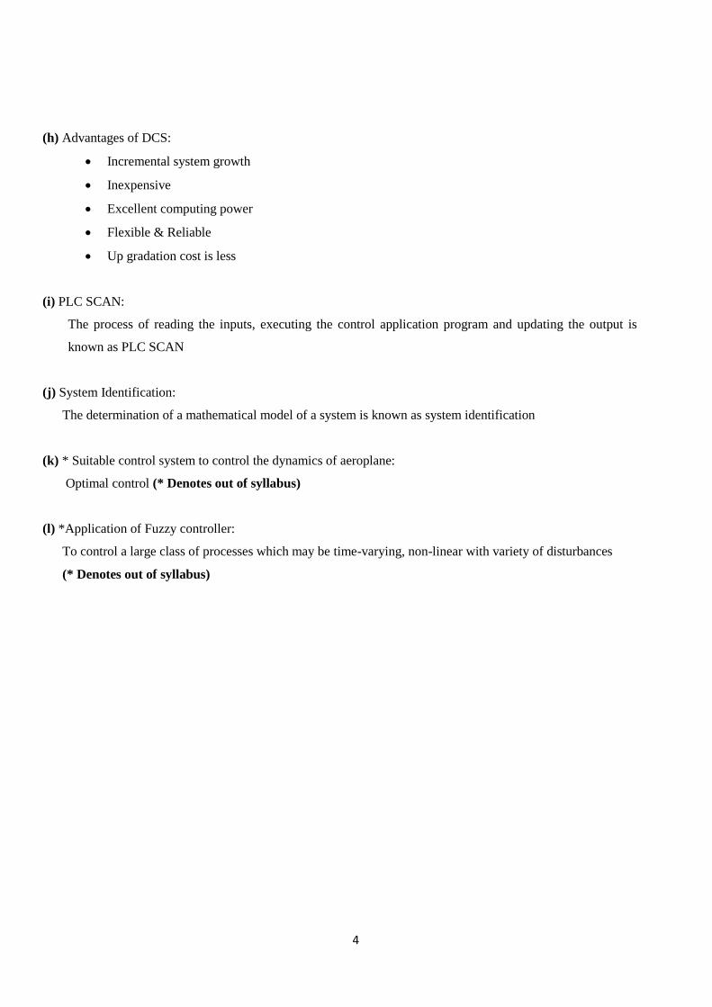
i.e.
1
2
:
;)(
nCF
CF
CF
C
VnV
Example:
)(11)(
)(1
0)(
10
11)1(
kxky
kukxkx
Here 2;11;1
0;
10
11
nCgF
01
11
10],[
UU
FggU
i.e. Rank of U is equal to 2, so the system is controllable
01
01
11
VV
V
i.e. Rank of V is equal to 2, so the system is observable
(OR)
3. (a) Enumerate the hardware and software requirements for computer based process
control 6M
Hardware requirements:
Multiplexers & De Multiplexers
ADC, DAC&Latches
Computer
Mass storage, operator console, Alarms
Line printers, CRTs...etc
Software requirements:
For the computer to perform controller functions the error must be determined and the
controller mode equations solved to determine the necessary output to the final control
element.
The above said operations are performed by the software
The computer must have program to solve the equations of P, I, D modes.

7
Nature of the software:
Soft ware format: The particular format of the software used for the computer controller
depends on the computer and its programming language
Examples: flow chart, Machine language, Assembly language
Input data operations: The first phase for software involved in the computer based
controllers to input the data and put them in to a suitable for controller mode evaluation
Controller modes: The operation of controller action is entirely taken over by software
with in the computer i.e. by programs
(b) Describe the conversion of state variable representation to transfer function model,
with an example 6M
State Model is combination of State and output equations. For continuous-time system the state
model is given by: )2(.........)(.)()(
)1(......)()()(
tuDtCxty
tButAxtx
State Model is combination of State and output equations. For Discrete-time system the state
model is given by: )4(...........)(.)()(
)3(......)()()1(
kuDkCxky
kgukFxkx
For continuous-time system we use Laplace transforms and for discrete-time system we use
Z-transforms
For Continuous-time system state model:
Take Laplace transform on both sides for equations (1) & (2) we get the following expressions:
DBAsICfunctiontransfer
sU
sY
sDUsBUAsICsDUsCXsYtuDtCxLTtyLT
sBUAsIsXsBUsAXssXtButAxLTtxLT
1
1
1
)()(
)(
)()()()()()()}(.)({)}({
)()()()()()()}()({)}({
(or)
For Discrete-time system state model:
Take the Z-transform on both sides for equations (3) & (4) we get the following expressions:
DgFzICzU
zY
zDUzgUFzICzDUzCXkuDkCxZkyZ
zgUFzIzXzgUzFXzzXkgukFxZkxZ
1
1
1
)()(
)(
)()()()()(})(.)({)}({
)()()()()()(})()({)}1({
Note: Take your own example and obtain the transfer function

8
UNIT-II
4. (a) Explain the mathematical modelling of I order system with and without pure
delay 4M
The transfer function for the first order without delay continuous-time system is given by
the expression
)1(1)(
)(
s
k
sM
sY
The equation (1) is rearranged as follows
)2()()()(1)(
)(skMssYsY
s
k
sM
sY
Take the inverse Laplace transform for the equation (2)
)3()()()}({)}()({ 11 tkmdt
dytyskMLssYsYL
Equation (3) is the differential equation that describes the continuous-time I order system
Conversion of Continuous-time system into Discrete-time system:
)()(
1()(1)(
)()(
nmtm
nynyTdt
tdy
nyty
With the above replacements equation (3) becomes:
TnmkT
nyny
nmT
kTny
Tnynkmnyny
Tny
);()1()(
)()1()()(1()(1
)(
The transfer function for the first order with delay continuous-time system is given by the
expression
)1(1)(
)(
s
ke
sM
sY std
The equation (1) is rearranged as follows
)2()()()(1)(
)(sMkessYsY
s
ke
sM
sY stst
d
d
Take the inverse Laplace transform for the equation (2)
)3()()()}({)}()({ 11 dst
ttkmdt
dytysMkeLssYsYL d
Equation (3) is the differential equation that describes the continuous-time I order system with
delay
9
Conversion of Continuous-time system into Discrete-time system:
)()(
1()(1)(
)()(
od nnmttm
nynyTdt
tdy
nyty
With the above replacements equation (3) becomes:
TnnmkT
nyny
nnmT
kTny
Tnynnkmnyny
Tny
o
oo
);()1()(
)()1()()(1()(1
)(
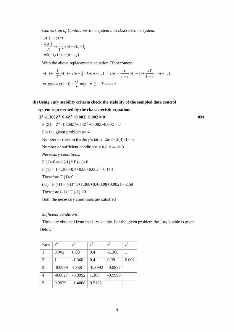
(b) Using Jury stability criteria check the stability of the sampled data control
system represented by the characteristic equation:
Z4 -1.368Z3+0.4Z2 +0.08Z+0.002 = 0 8M
F (Z) = Z4 -1.368Z3+0.4Z2 +0.08Z+0.002 = 0
For the given problem n= 4
Number of rows in the Jury’s table: 2n-3= 2(4)-3 = 5
Number of sufficient conditions = n-1 = 4-1= 3
Necessary conditions:
F (1)>0 and (-1) n F (-1)>0
F (1) = 1-1.368+0.4+0.08+0.002 = 0.114
Therefore F (1)>0
(-1) n F (-1) = (-1)4[1+1.368+0.4-0.08+0.002] = 2.69
Therefore (-1) n F (-1) >0
Both the necessary conditions are satisfied
Sufficient conditions:
These are obtained from the Jury’s table. For the given problem the Jury’s table is given
Below:
Row z0 z1 z2 z3 z4
1 0.002 0.08 0.4 -1.368 1
2 1 -1.368 0.4 0.08 0.002
3 -0.9999 1.368 -0.3992 -0.0827
4 -0.0827 -0.3992 1.368 -0.9999
5 0.9929 -1.4008 0.5122

10
The sufficient conditions for the given problem:
True
True
True
5122.09999.05122.09999.0
0827.09999.00827.09999.0
1002.0
Both the necessary and sufficient conditions are satisfied. So the given system is stable
(OR)
5. (a) Write short note on stability in Z-domain 4M
The following figure shows the Block diagram of the closed loop sampled data control
system
The transfer function of the closed loop sampled data control system is given by the
expression:)(1
)(
)}()({1
)}({
)(
)(
zGH
zG
sHsGZ
sGZ
zR
zC
The characteristic equation for the system is: 0)(1 zGH
If the roots of the characteristic equation (poles) are inside the unit circle the system is
stable
If the roots of the characteristic equation (poles) are outside the unit circle the system is
unstable
If the roots of the characteristic equation (poles) lies on the unit circle the system is
marginally stable
G(s)
H(s)
r (t) c (t)
11
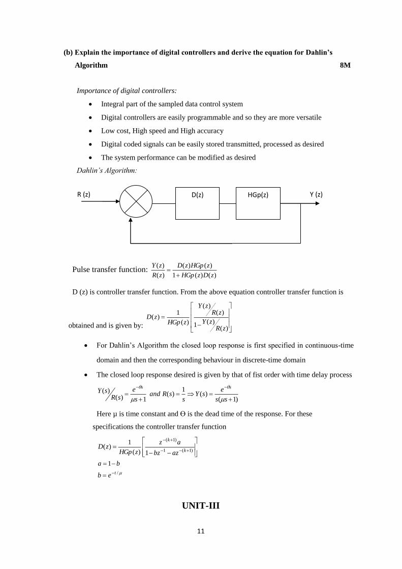
(b) Explain the importance of digital controllers and derive the equation for Dahlin’s
Algorithm 8M
Importance of digital controllers:
Integral part of the sampled data control system
Digital controllers are easily programmable and so they are more versatile
Low cost, High speed and High accuracy
Digital coded signals can be easily stored transmitted, processed as desired
The system performance can be modified as desired
Dahlin’s Algorithm:
Pulse transfer function: )()(1
)()(
)(
)(
zDzHGp
zHGpzD
zR
zY
D (z) is controller transfer function. From the above equation controller transfer function is
obtained and is given by:
)()(
1
)()(
)(
1)(
zRzY
zRzY
zHGpzD
For Dahlin’s Algorithm the closed loop response is first specified in continuous-time
domain and then the corresponding behaviour in discrete-time domain
The closed loop response desired is given by that of fist order with time delay process
)1(
)(1
)(1)(
)(
ss
esY
ssRand
s
e
sRsY
ss
Here µ is time constant and ϴ is the dead time of the response. For these
specifications the controller transfer function
/
)1(1
)1(
1
1)(
1)(
t
k
k
eb
ba
azbz
az
zHGpzD
UNIT-III
HGp(z) D(z) R (z) Y (z)

12
6. (a) With a neat sketch, explain the basic elements of distributed control system (DCS) 8M
DCS is Layered structure. Here each layer consists of group of tasks to be performed on the lower
layer by
getting instructions from the higher level
Level-1:
It is known as Field level
It consists of specially designed dedicated controllers.
The functions of this level are: Emergency shutdown, Provides manual backup when other
layers are failed
Level-2:
It is area control level. It consists of a direct digital control link. Functions of this Level are:
Process data collection
Message for alarm signals
Open loop and Closed loop control
Hardware test
Level-3: It is known as plant control level. It consists of supervisory control link
Functions of this level are:
Optimal control
Adaptive control
Level-4:
It is known as plant management level. Functions of this level are:

13
Resource scheduling
Production planning
Management functions related to process or production management.
(b) Write short note on PLC Ladder programming 4M
It is one of the popular programming language for PLC’s.
It consists of symbols for specific functions.
This approach consists several Ladder instructions for various operations
Basic Ladder Instructions:
1. Normally open contact:
2. Normally closed contact:
3. Turn on output:
4. Turn off output
(OR)
7. (a) With the help of neat schematic, explain the principle of PLC. State the applications of PLC.
Power Supply:
Provides the voltage needed to run the primary PLC components
14
I/O Module:
Provides signal conversion and isolation between the internal logic- level signals inside the PLC
and the field’s high level signal.
Processor:
Provides intelligence to command and govern the activities of the entire PLC systems.
Programming device:
Used to enter the desired program that will determine the sequence of operation and control of
process equipment or driven machine.
PLC Applications:
PLC’s are used in many industries for one or more of the functional areas.
Sequence control, timing, counting, and data calculation.
Quick change of machine or process logic, to manufacture different items using the same
machine or process equipment.
Auto compilation of production/consumption/Down time/Maintenance data.
Batch or Continuous process control.
Open loop or feedback control, process data acquisition and display
Precise motion/Position control
(b) Write short note on Configuration and Communication facilities for DCS 6M
Configuration:
Distributed control systems are of 2 types: (i) Bus based DCS (ii) Non-Bus based DCS
For the Non-Bus based DCS, the configuration is done by the manufacturer. For the Bus-based
DCS the configuration is done via key board through an operating system
Configuration of DCS consists of two Steps:
Step-1: Configuration of operating system
Step-2: Configuration of controller functions
Step:1 The configuration of operating system is done to perform certain tasks such as:
Composition between group and overview displays
Period for trends
Message tables
High way station priorities
Step: 2 Configuration of controller function is carried out to obtain complete control strategy. The
configuration is obtained via software modules which are stored in the memory. These modules
are called as Algorithms. Linking of these algorithms is performed via addresses. This is known
as Software wiring.
Communication facilities:
The communication paths are essential for DCS
The path must be implemented from top to the bottom of the system, to transfer any necessary
control action down to the individual final elements or to collect the actual information from
them
Short and long distance buses will be used in a combination to cover a big area of distributed
plants like steel, chemical, mining industry

15
For short distances, the star connection is applicable which usually combined with bus and
point-point connection will result in to a mesh network.
At level-1 usually point-point connection will be applied to connect individual sensors and
actuators to analog and digital inputs and outputs of the local field station.
Recent advance for this is PROFIBUS (process field bus).
For shorter distances an instrumentation bus IEEE-488 can be applied.
UNIT-IV
8. (a) Explain the basic steps in System identification 6M
System Identification:
The determination of a mathematical model of a system is known as system identification.Mathematical
models deals with Linear Time invariant Single input Single output discrete time System is described
by difference equation. The proposed method is for estimating he coefficients of difference equations
A set of “N” linear algebraic equations are formulated “N” is the number of measurements.
Derive the canonical equation whose solution yields the Parameter estimate of θ (N) ϴ is the vector
parameter
under identification
Estimate of initial condition of the dynamic equation is required.
(N+n measurements are taken and N+n equations are formed where n is the order of the difference
equation).
Example:
Consider the simple first order system
y(k) + a1 y(k-1) = b1u(k-1)
Definition of the problem:
For the given input sequence u(-1) , u(0) , u(1), u(2) , -----, u(n-1)
The output is y(0), y(1), y(2), …. , y(n)
Find out the parameter a1 and b1 and the initial condition y(-1)
Step: 1
y(0) + a1y(-1)= b1 u(-1)
y(1) + a1y(0) = b1 u(0)
Y(2) + a1y(1) = b1 u(1)
.
.
.
.
y(N) + a1y(N-1) = b1u(N-1)
16
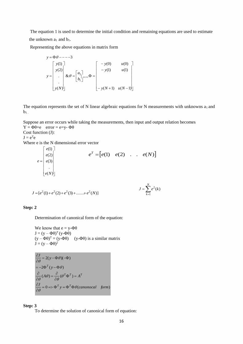
The equation 1 is used to determine the initial condition and remaining equations are used to estimate
the unknown a1 and b1.
Representing the above equations in matrix form
The equation represents the set of N linear algebraic equations for N measurements with unknowns a1 and
b1 .
Suppose an error occurs while taking the measurements, then input and output relation becomes
Y = Φθ+e error = e=y- Φθ
Cost function (J):
J = eTe
Where e is the N dimensional error vector
Step: 2
Determination of canonical form of the equation:
We know that e = y-Φθ
J = (y – Φθ)T (y-Φθ)
(y – Φθ)T = (y-Φθ) (y-Φθ) is a similar matrix
J = (y – Φθ)2
Step: 3
To determine the solution of canonical form of equation:
)(..)2()1( NeeeeT
)1()1(
)1()1(
)0()0(
,,,,&
)(
.
.
)2(
)1(
3
1
1
NuNy
uy
uy
b
a
Ny
y
y
y
y
)(
.
)3(
)2(
)1(
Ne
e
e
e
e
)](.......)3()2()1([ 2222 NeeeeJ
N
k
keJ
1
2 )(
)(0
)()(
)(2
))((2
formcanonocalyJ
AA
y
yJ
TT
TTT
T

17
Step: 4
Initial condition estimation:
From (1) we have got
y(0) + a1y(-1) = b1u(-1)
y(-1) = [b1u(-1) – y(0)] / a1
Where it is assumed that condition a1 ≠ 0 & u(-1) is a known
(b) Write about Self tuning regulator with an example 6M
In this approach the two functional blocks are used: (i) Parameter estimator (ii) Parameter adaptor
The parameter estimator continuously estimates the system parameters based on the system input
N
k
N
kT
N
k
N
k
N
k
N
kT
TT
kuky
kyky
y
kukuky
kukyky
y
1
1
1
0
21
0
1
0
1
0
2
1
)1()(
)1()(
)()()(
)()()(
)(

18
and output.
The parameter adaptor continuously adjusts the control parameters so that the performance of Indies
is maximized.
The following method are used for parameter estimation
Least square method
Method of instrumental variables
Maximum likelihood method
Stochastic approximation method
(OR)
9. (a) Describe the role of expert system in process control 6M
Expert or knowledge based systems are artificial intelligent systems that capture the expertise of
Human experts who are knowledgeable in a particular application domain. The information presented
to expert system may be
Functional
Experimental
Incomplete
Judgmental
Speculative
Uncertain
Fuzzy
Intuitive
19
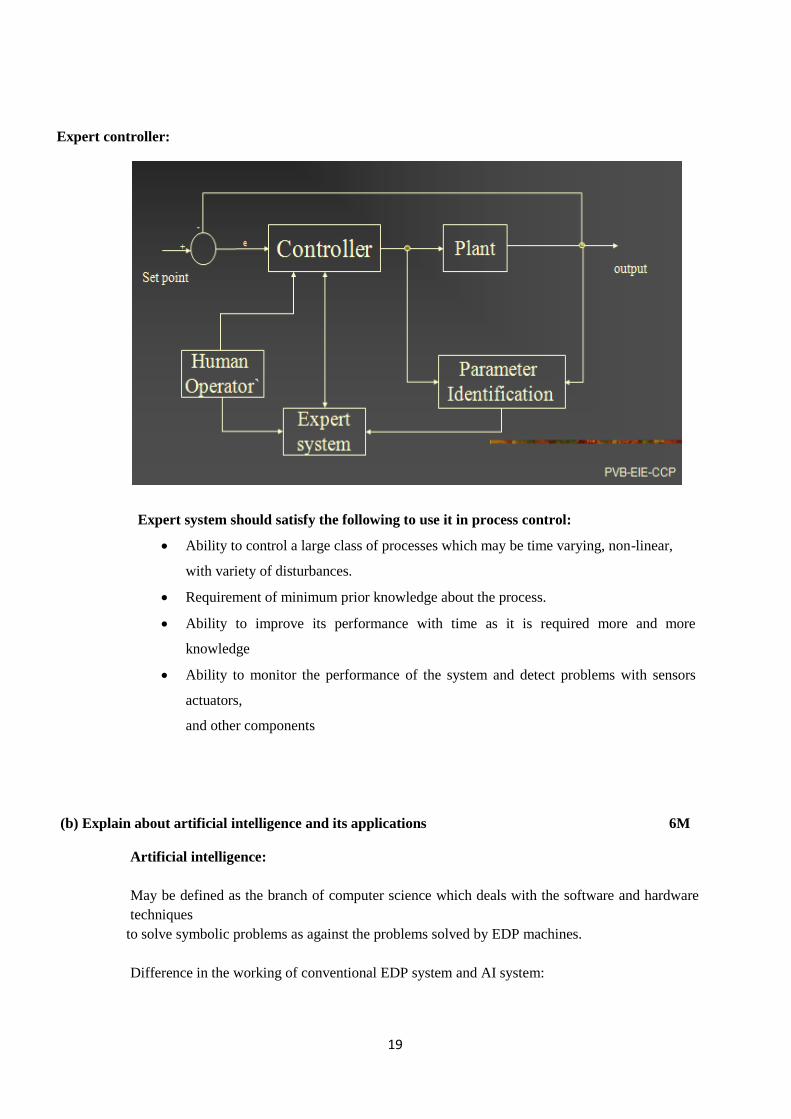
Expert controller:
Expert system should satisfy the following to use it in process control:
Ability to control a large class of processes which may be time varying, non-linear,
with variety of disturbances.
Requirement of minimum prior knowledge about the process.
Ability to improve its performance with time as it is required more and more
knowledge
Ability to monitor the performance of the system and detect problems with sensors
actuators,
and other components
(b) Explain about artificial intelligence and its applications 6M
Artificial intelligence:
May be defined as the branch of computer science which deals with the software and hardware
techniques
to solve symbolic problems as against the problems solved by EDP machines.
Difference in the working of conventional EDP system and AI system:

20
Artificial intelligence systems can understand screw driver and relate it to screw or conveyer
belt. These systems can understand the meaning of scheduling and relate to operation sequence.
AI programs contain information like data, collection of separate words or characters and
knowledge. Like inter connection of words, structure and relation map. The three outputs of AI
system are Opinions, analysis and recommendation.
AI systems are divided as follows:
Natural language systems
Perception system for vision, speech, and touch
Expert or knowledge based system
Natural language systems:
AI systems that should be able to understand the natural languages as humans being understand.
Such systems have easy means of communication with computer.
Perception systems for vision, speech, and touch:
They can interpret visual scene or make inference about quality or physical orientation of the object.
Vision system of robot falls into this category.
21
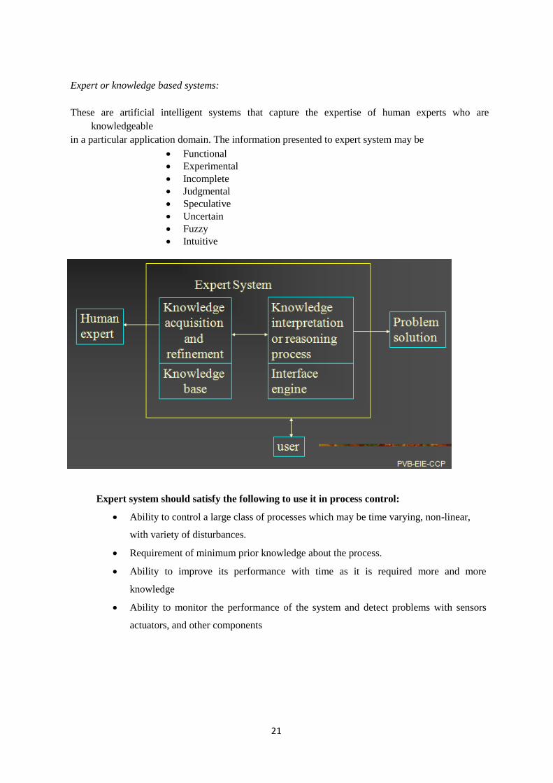
Expert or knowledge based systems:
These are artificial intelligent systems that capture the expertise of human experts who are
knowledgeable
in a particular application domain. The information presented to expert system may be
Functional
Experimental
Incomplete
Judgmental
Speculative
Uncertain
Fuzzy
Intuitive
Expert system should satisfy the following to use it in process control:
Ability to control a large class of processes which may be time varying, non-linear,
with variety of disturbances.
Requirement of minimum prior knowledge about the process.
Ability to improve its performance with time as it is required more and more
knowledge
Ability to monitor the performance of the system and detect problems with sensors
actuators, and other components

22
General structure of the expert system:

23
Interface engine: It tries to determine the knowledge which solves the problem in hand.
Explanator: Explain the reason for concluding the particular solution. The explanation given by the
explanator may be reviewed by the human expert. If the human expert does not accept the conclusion
then he provides some more knowledge in terms of rules, facts, and heuristics.
Learner:
Learner accepts the new knowledge and stores in its data base.
Solution reviewer:
It relooks into the problem in hand and tries to find another solution
Note: The process of reasoning, solution explanation, learning, and solution review may be repeated till
the human being accepts the Solution determined by interface engine.
24
Scheme &Solutions of EI 414
Prepared By:
P. Vinodh Babu
Associate Professor
Department of EIE
Bapatla Engineering College
Bapatla-522102