Scheduling EC-1 - California Energy Commission · Scheduling is the development of a written plan...
94
Scheduling EC-1 Categories EC Erosion Control ; SE Sediment Control : TC Tracking Control : WE Wind Erosion Control : NS Non-Stormwater Management Control WM Waste Management and Materials Pollution Control Legend: ; Primary Objective : Secondary Objective Targeted Constituents Sediment ; Nutrients Trash Metals Bacteria Oil and Grease Organics Potential Alternatives None Description and Purpose Scheduling is the development of a written plan that includes sequencing of construction activities and the implementation of BMPs such as erosion control and sediment control while taking local climate (rainfall, wind, etc.) into consideration. The purpose is to reduce the amount and duration of soil exposed to erosion by wind, rain, runoff, and vehicle tracking, and to perform the construction activities and control practices in accordance with the planned schedule. Suitable Applications Proper sequencing of construction activities to reduce erosion potential should be incorporated into the schedule of every construction project especially during rainy season. Use of other, more costly yet less effective, erosion and sediment control BMPs may often be reduced through proper construction sequencing. Limitations Environmental constraints such as nesting season prohibitions reduce the full capabilities of this BMP. Implementation Avoid rainy periods. Schedule major grading operations during dry months when practical. Allow enough time before rainfall begins to stabilize the soil with vegetation or physical means or to install sediment trapping devices. Plan the project and develop a schedule showing each phase November 2009 California Stormwater BMP Handbook 1 of 3 Construction www.casqa.org
Transcript of Scheduling EC-1 - California Energy Commission · Scheduling is the development of a written plan...

Scheduling EC-1 Categories
EC Erosion Control SE Sediment Control TC Tracking Control WE Wind Erosion Control
NS Non-Stormwater Management Control
WM Waste Management and Materials Pollution Control
Legend:
Primary Objective
Secondary Objective
Targeted Constituents
Sediment Nutrients Trash Metals Bacteria Oil and Grease Organics
Potential Alternatives
None
Description and Purpose Scheduling is the development of a written plan that includes sequencing of construction activities and the implementation of BMPs such as erosion control and sediment control while taking local climate (rainfall, wind, etc.) into consideration. The purpose is to reduce the amount and duration of soil exposed to erosion by wind, rain, runoff, and vehicle tracking, and to perform the construction activities and control practices in accordance with the planned schedule.
Suitable Applications Proper sequencing of construction activities to reduce erosion potential should be incorporated into the schedule of every construction project especially during rainy season. Use of other, more costly yet less effective, erosion and sediment control BMPs may often be reduced through proper construction sequencing.
Limitations Environmental constraints such as nesting season
prohibitions reduce the full capabilities of this BMP.
Implementation Avoid rainy periods. Schedule major grading operations
during dry months when practical. Allow enough time before rainfall begins to stabilize the soil with vegetation or physical means or to install sediment trapping devices.
Plan the project and develop a schedule showing each phase
November 2009 California Stormwater BMP Handbook 1 of 3
Construction
www.casqa.org

Scheduling EC-1
of construction. Clearly show how the rainy season relates to soil disturbing and re-stabilization activities. Incorporate the construction schedule into the SWPPP.
Include on the schedule, details on the rainy season implementation and deployment of:
- Erosion control BMPs
- Sediment control BMPs
- Tracking control BMPs
- Wind erosion control BMPs
- Non-stormwater BMPs
- Waste management and materials pollution control BMPs
Include dates for activities that may require non-stormwater discharges such as dewatering, sawcutting, grinding, drilling, boring, crushing, blasting, painting, hydro-demolition, mortar mixing, pavement cleaning, etc.
Work out the sequencing and timetable for the start and completion of each item such as site clearing and grubbing, grading, excavation, paving, foundation pouring utilities installation, etc., to minimize the active construction area during the rainy season.
- Sequence trenching activities so that most open portions are closed before new trenching begins.
- Incorporate staged seeding and re-vegetation of graded slopes as work progresses.
- Schedule establishment of permanent vegetation during appropriate planting time for specified vegetation.
Non-active areas should be stabilized as soon as practical after the cessation of soil disturbing activities or one day prior to the onset of precipitation.
Monitor the weather forecast for rainfall.
When rainfall is predicted, adjust the construction schedule to allow the implementation of soil stabilization and sediment treatment controls on all disturbed areas prior to the onset of rain.
Be prepared year round to deploy erosion control and sediment control BMPs. Erosion may be caused during dry seasons by un-seasonal rainfall, wind, and vehicle tracking. Keep the site stabilized year round, and retain and maintain rainy season sediment trapping devices in operational condition.
Apply permanent erosion control to areas deemed substantially complete during the project’s defined seeding window.
Costs Construction scheduling to reduce erosion may increase other construction costs due to reduced economies of scale in performing site grading. The cost effectiveness of scheduling techniques should be compared with the other less effective erosion and sedimentation controls to achieve a cost effective balance.
November 2009 California Stormwater BMP Handbook 2 of 3
Construction
www.casqa.org

Scheduling EC-1
November 2009 California Stormwater BMP Handbook 3 of 3
Construction
www.casqa.org
Inspection and Maintenance Verify that work is progressing in accordance with the schedule. If progress deviates, take
corrective actions.
Amend the schedule when changes are warranted.
Amend the schedule prior to the rainy season to show updated information on the deployment and implementation of construction site BMPs.
References Stormwater Quality Handbooks Construction Site Best Management Practices (BMPs) Manual, State of California Department of Transportation (Caltrans), November 2000.
Stormwater Management for Construction Activities Developing Pollution Prevention Plans and Best Management Practices (EPA 832-R-92-005), U.S. Environmental Protection Agency, Office of Water, September 1992.
Preservation Of Existing Vegetation EC-2 Categories
EC Erosion Control SE Sediment Control TC Tracking Control WE Wind Erosion Control
NS Non-Stormwater Management Control
WM Waste Management and Materials Pollution Control
Legend:
Primary Objective
Secondary Objective
Targeted Constituents
Sediment Nutrients Trash Metals Bacteria Oil and Grease Organics
Potential Alternatives
None
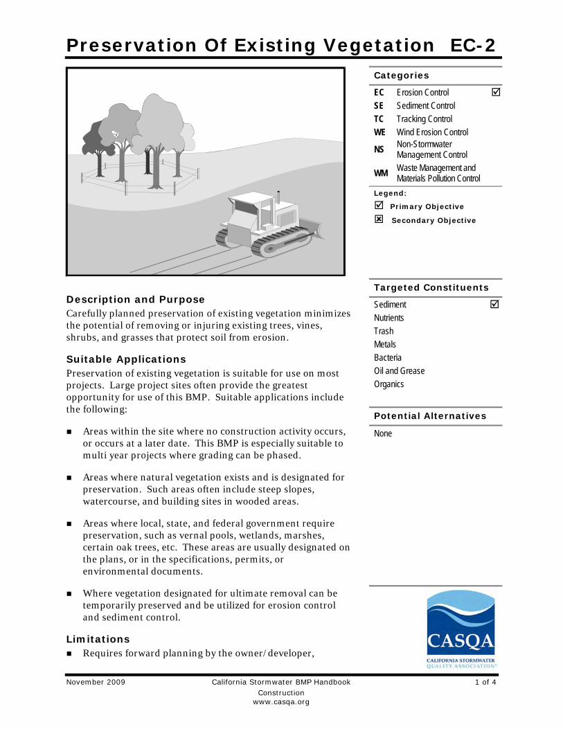
Description and Purpose Carefully planned preservation of existing vegetation minimizes the potential of removing or injuring existing trees, vines, shrubs, and grasses that protect soil from erosion.
Suitable Applications Preservation of existing vegetation is suitable for use on most projects. Large project sites often provide the greatest opportunity for use of this BMP. Suitable applications include the following:
Areas within the site where no construction activity occurs, or occurs at a later date. This BMP is especially suitable to multi year projects where grading can be phased.
Areas where natural vegetation exists and is designated for preservation. Such areas often include steep slopes, watercourse, and building sites in wooded areas.
Areas where local, state, and federal government require preservation, such as vernal pools, wetlands, marshes, certain oak trees, etc. These areas are usually designated on the plans, or in the specifications, permits, or environmental documents.
Where vegetation designated for ultimate removal can be temporarily preserved and be utilized for erosion control and sediment control.
Limitations Requires forward planning by the owner/developer,
November 2009 California Stormwater BMP Handbook 1 of 4
Construction
www.casqa.org

Preservation Of Existing Vegetation EC-2
contractor, and design staff.
Limited opportunities for use when project plans do not incorporate existing vegetation into the site design.
For sites with diverse topography, it is often difficult and expensive to save existing trees while grading the site satisfactory for the planned development.
Implementation The best way to prevent erosion is to not disturb the land. In order to reduce the impacts of new development and redevelopment, projects may be designed to avoid disturbing land in sensitive areas of the site (e.g., natural watercourses, steep slopes), and to incorporate unique or desirable existing vegetation into the site’s landscaping plan. Clearly marking and leaving a buffer area around these unique areas during construction will help to preserve these areas as well as take advantage of natural erosion prevention and sediment trapping.
Existing vegetation to be preserved on the site must be protected from mechanical and other injury while the land is being developed. The purpose of protecting existing vegetation is to ensure the survival of desirable vegetation for shade, beautification, and erosion control. Mature vegetation has extensive root systems that help to hold soil in place, thus reducing erosion. In addition, vegetation helps keep soil from drying rapidly and becoming susceptible to erosion. To effectively save existing vegetation, no disturbances of any kind should be allowed within a defined area around the vegetation. For trees, no construction activity should occur within the drip line of the tree.
Timing Provide for preservation of existing vegetation prior to the commencement of clearing and
grubbing operations or other soil disturbing activities in areas where no construction activity is planned or will occur at a later date.
Design and Layout Mark areas to be preserved with temporary fencing. Include sufficient setback to protect
roots.
− Orange colored plastic mesh fencing works well.
− Use appropriate fence posts and adequate post spacing and depth to completely support the fence in an upright position.
Locate temporary roadways, stockpiles, and layout areas to avoid stands of trees, shrubs, and grass.
Consider the impact of grade changes to existing vegetation and the root zone.
Maintain existing irrigation systems where feasible. Temporary irrigation may be required.
Instruct employees and subcontractors to honor protective devices. Prohibit heavy equipment, vehicular traffic, or storage of construction materials within the protected area.
November 2009 California Stormwater BMP Handbook 2 of 4
Construction
www.casqa.org
Preservation Of Existing Vegetation EC-2
Costs There is little cost associated with preserving existing vegetation if properly planned during the project design, and these costs may be offset by aesthetic benefits that enhance property values. During construction, the cost for preserving existing vegetation will likely be less than the cost of applying erosion and sediment controls to the disturbed area. Replacing vegetation inadvertently destroyed during construction can be extremely expensive, sometimes in excess of $10,000 per tree.
Inspection and Maintenance During construction, the limits of disturbance should remain clearly marked at all times. Irrigation or maintenance of existing vegetation should be described in the landscaping plan. If damage to protected trees still occurs, maintenance guidelines described below should be followed:
Verify that protective measures remain in place. Restore damaged protection measures immediately.
Serious tree injuries shall be attended to by an arborist.
Damage to the crown, trunk, or root system of a retained tree shall be repaired immediately.
Trench as far from tree trunks as possible, usually outside of the tree drip line or canopy. Curve trenches around trees to avoid large roots or root concentrations. If roots are encountered, consider tunneling under them. When trenching or tunneling near or under trees to be retained, place tunnels at least 18 in. below the ground surface, and not below the tree center to minimize impact on the roots.
Do not leave tree roots exposed to air. Cover exposed roots with soil as soon as possible. If soil covering is not practical, protect exposed roots with wet burlap or peat moss until the tunnel or trench is ready for backfill.
Cleanly remove the ends of damaged roots with a smooth cut.
Fill trenches and tunnels as soon as possible. Careful filling and tamping will eliminate air spaces in the soil, which can damage roots.
If bark damage occurs, cut back all loosened bark into the undamaged area, with the cut tapered at the top and bottom and drainage provided at the base of the wood. Limit cutting the undamaged area as much as possible.
Aerate soil that has been compacted over a trees root zone by punching holes 12 in. deep with an iron bar, and moving the bar back and forth until the soil is loosened. Place holes 18 in. apart throughout the area of compacted soil under the tree crown.
Fertilization
− Fertilize stressed or damaged broadleaf trees to aid recovery.
− Fertilize trees in the late fall or early spring.
November 2009 California Stormwater BMP Handbook 3 of 4
Construction
www.casqa.org

Preservation Of Existing Vegetation EC-2
November 2009 California Stormwater BMP Handbook 4 of 4
Construction
www.casqa.org
- Apply fertilizer to the soil over the feeder roots and in accordance with label instructions, but never closer than 3 ft to the trunk. Increase the fertilized area by one-fourth of the crown area for conifers that have extended root systems.
Retain protective measures until all other construction activity is complete to avoid damage during site cleanup and stabilization.
References County of Sacramento Tree Preservation Ordinance, September 1981.
Stormwater Quality Handbooks Construction Site Best Management Practices (BMPs) Manual, State of California Department of Transportation (Caltrans), November 2000.
Stormwater Management of the Puget Sound Basin, Technical Manual, Publication #91-75, Washington State Department of Ecology, February 1992.
Water Quality Management Plan for The Lake Tahoe Region, Volume II, Handbook of Management Practices, Tahoe Regional Planning Agency, November 1988.

Soil Binders EC-5
November 2009 California Stormwater BMP Handbook 1 of 8
Construction
www.casqa.org
Description and Purpose Soil binding consists of application and maintenance of a soil stabilizer to exposed soil surfaces. Soil binders are materials applied to the soil surface to temporarily prevent water and wind induced erosion of exposed soils on construction sites.
Suitable Applications Soil binders are typically applied to disturbed areas requiring temporary protection. Because soil binders, when used as a stand-alone practice, can often be incorporated into the soil, they are a good alternative to mulches in areas where grading activities will soon resume. Soil binders are commonly used in the following areas:
Rough graded soils that will be inactive for a short period of time
Soil stockpiles
Temporary haul roads prior to placement of crushed rock
Compacted soil road base
Construction staging, materials storage, and layout areas
Limitations Soil binders are temporary in nature and may need
reapplication.
Categories
EC Erosion Control SE Sediment Control TC Tracking Control WE Wind Erosion Control
NS Non-Stormwater Management Control
WM Waste Management and Materials Pollution Control
Legend:
Primary Category
Secondary Category
Targeted Constituents
Sediment Nutrients Trash Metals Bacteria Oil and Grease Organics
Potential Alternatives
EC-3 Hydraulic Mulch
EC-4 Hydroseeding
EC-6 Straw Mulch
EC-7 Geotextiles and Mats
EC-8 Wood Mulching

Soil Binders EC-5
November 2009 California Stormwater BMP Handbook 2 of 8
Construction
www.casqa.org
Soil binders require a minimum curing time until fully effective, as prescribed by the manufacturer. Curing time may be 24 hours or longer. Soil binders may need reapplication after a storm event.
Soil binders will generally experience spot failures during heavy rainfall events. If runoff penetrates the soil at the top of a slope treated with a soil binder, it is likely that the runoff will undercut the stabilized soil layer and discharge at a point further down slope.
Plant-material-based soil binders do not generally hold up to pedestrian or vehicular traffic across treated areas as well as polymeric emulsion blends or cementitious-based binders.
Soil binders may not sufficiently penetrate compacted soils.
Some soil binders are soil texture specific in terms of their effectiveness. For example, polyacrylamides (PAMs) work very well on silt and clayey soils but their performance decreases dramatically in sandy soils.
Some soil binders may not perform well with low relative humidity. Under rainy conditions, some agents may become slippery or leach out of the soil.
Soil binders may not cure if low temperatures occur within 24 hours of application.
The water quality impacts of some chemical soil binders are relatively unknown and some may have water quality impacts due to their chemical makeup.
Implementation General Considerations
Soil binders should conform to local municipality specifications and requirements.
Site soil types will dictate appropriate soil binders to be used.
A soil binder must be environmentally benign (non-toxic to plant and animal life), easy to apply, easy to maintain, economical, and should not stain paved or painted surfaces. Soil binders should not pollute stormwater when cured. Obtain a Material Safety Data Sheet (MSDS) from the manufacturer to ensure non-toxicity.
Stormwater runoff from PAM treated soils should pass through one of the following sediment control BMP prior to discharging to surface waters.
- When the total drainage area is greater than or equal to 5 acres, PAM treated areas should drain to a sediment basin.
- Areas less than 5 acres should drain to sediment control BMPs, such as a sediment trap, or a series of check dams. The total number of check dams used should be maximized to achieve the greatest amount of settlement of sediment prior to discharging from the site. Each check dam should be spaced evenly in the drainage channel through which stormwater flows are discharged off site.
Performance of soil binders depends on temperature, humidity, and traffic across treated areas.

Soil Binders EC-5
November 2009 California Stormwater BMP Handbook 3 of 8
Construction
www.casqa.org
Avoid over spray onto roads, sidewalks, drainage channels, existing vegetation, etc.
Additional guidance on the comparison and selection of temporary slope stabilization methods is provided in Appendix F of the Handbook.
Selecting a Soil Binder Properties of common soil binders used for erosion control are provided on Table 1 at the end of this Fact Sheet. Use Table 1 to select an appropriate soil binder. Refer to WE-1, Wind Erosion Control, for dust control soil binders.
Factors to consider when selecting a soil binder include the following:
Suitability to situation - Consider where the soil binder will be applied, if it needs a high resistance to leaching or abrasion, and whether it needs to be compatible with any existing vegetation. Determine the length of time soil stabilization will be needed, and if the soil binder will be placed in an area where it will degrade rapidly. In general, slope steepness is not a discriminating factor for the listed soil binders.
Soil types and surface materials - Fines and moisture content are key properties of surface materials. Consider a soil binder's ability to penetrate, likelihood of leaching, and ability to form a surface crust on the surface materials.
Frequency of application - The frequency of application is related to the functional longevity of the binder, which can be affected by subgrade conditions, surface type, climate, and maintenance schedule.
Frequent applications could lead to high costs. Application frequency may be minimized if the soil binder has good penetration, low evaporation, and good longevity. Consider also that frequent application will require frequent equipment clean up.
Plant-Material-Based (Short Lived, <6 months) Binders Guar: Guar is a non-toxic, biodegradable, natural galactomannan-based hydrocolloid treated with dispersant agents for easy field mixing. It should be mixed with water at the rate of 11 to 15 lb per 1,000 gallons. Recommended minimum application rates are as follows:
Application Rates for Guar Soil Stabilizer
Slope (H:V): Flat 4:1 3:1 2:1 1:1
lb/acre: 40 45 50 60 70
Psyllium: Psyllium is composed of the finely ground muciloid coating of plantago seeds that is applied as a dry powder or in a wet slurry to the surface of the soil. It dries to form a firm but rewettable membrane that binds soil particles together, but permits germination and growth of seed. Psyllium requires 12 to 18 hours drying time. Application rates should be from 80 to 200 lb/acre, with enough water in solution to allow for a uniform slurry flow.
Starch: Starch is non-ionic, cold water soluble (pre-gelatinized) granular cornstarch. The material is mixed with water and applied at the rate of 150 lb/acre. Approximate drying time is 9 to 12 hours.

Soil Binders EC-5
November 2009 California Stormwater BMP Handbook 4 of 8
Construction
www.casqa.org
Plant-Material-Based (Long Lived, 6-12 months) Binders Pitch and Rosin Emulsion: Generally, a non-ionic pitch and rosin emulsion has a minimum solids content of 48%. The rosin should be a minimum of 26% of the total solids content. The soil stabilizer should be non-corrosive, water dilutable emulsion that upon application cures to a water insoluble binding and cementing agent. For soil erosion control applications, the emulsion is diluted and should be applied as follows:
For clayey soil: 5 parts water to 1 part emulsion
For sandy soil: 10 parts water to 1 part emulsion
Application can be by water truck or hydraulic seeder with the emulsion and product mixture applied at the rate specified by the manufacturer.
Polymeric Emulsion Blend Binders Acrylic Copolymers and Polymers: Polymeric soil stabilizers should consist of a liquid or solid polymer or copolymer with an acrylic base that contains a minimum of 55% solids. The polymeric compound should be handled and mixed in a manner that will not cause foaming or should contain an anti-foaming agent. The polymeric emulsion should not exceed its shelf life or expiration date; manufacturers should provide the expiration date. Polymeric soil stabilizer should be readily miscible in water, non-injurious to seed or animal life, non-flammable, should provide surface soil stabilization for various soil types without totally inhibiting water infiltration, and should not re-emulsify when cured. The applied compound typically requires 12 to 24 hours drying time. Liquid copolymer should be diluted at a rate of 10 parts water to 1 part polymer and the mixture applied to soil at a rate of 1,175 gallons/acre.
Liquid Polymers of Methacrylates and Acrylates: This material consists of a tackifier/sealer that is a liquid polymer of methacrylates and acrylates. It is an aqueous 100% acrylic emulsion blend of 40% solids by volume that is free from styrene, acetate, vinyl, ethoxylated surfactants or silicates. For soil stabilization applications, it is diluted with water in accordance with the manufacturer’s recommendations, and applied with a hydraulic seeder at the rate of 20 gallons/acre. Drying time is 12 to 18 hours after application.
Copolymers of Sodium Acrylates and Acrylamides: These materials are non-toxic, dry powders that are copolymers of sodium acrylate and acrylamide. They are mixed with water and applied to the soil surface for erosion control at rates that are determined by slope gradient:
Slope Gradient (H:V)
lb/acre
Flat to 5:1 3.0 – 5.0
5:1 to 3:1 5.0 – 10.0
2:1 to 1:1 10.0 – 20.0
Poly-Acrylamide (PAM) and Copolymer of Acrylamide: Linear copolymer polyacrylamide for use as a soil binder is packaged as a dry flowable solid, as a liquid. Refer to the manufacturer’s recommendation for dilution and application rates as they vary based on liquid or dry form, site conditions and climate.
Limitations specific to PAM are as follows:

Soil Binders EC-5
November 2009 California Stormwater BMP Handbook 5 of 8
Construction
www.casqa.org
- Do not use PAM on a slope that flows into a water body without passing through a sediment trap or sediment basin.
- The specific PAM copolymer formulation must be anionic. Cationic PAM should not be used in any application because of known aquatic toxicity problems. Only the highest drinking water grade PAM, certified for compliance with ANSI/NSF Standard 60 for drinking water treatment, should be used for soil applications.
- PAM designated for erosion and sediment control should be “water soluble” or “linear” or “non-cross linked”.
- PAM should not be used as a stand-alone BMP to protect against water-based erosion. When combined with mulch, its effectiveness increases dramatically.
Hydro-Colloid Polymers: Hydro-Colloid Polymers are various combinations of dry flowable poly-acrylamides, copolymers and hydro-colloid polymers that are mixed with water and applied to the soil surface at rates of 55 to 60 lb/acre. Drying times are 0 to 4 hours.
Cementitious-Based Binders Gypsum: This is a formulated gypsum based product that readily mixes with water and mulch to form a thin protective crust on the soil surface. It is composed of high purity gypsum that is ground, calcined and processed into calcium sulfate hemihydrate with a minimum purity of 86%. It is mixed in a hydraulic seeder and applied at rates 4,000 to 12,000 lb/acre. Drying time is 4 to 8 hours.
Applying Soil Binders After selecting an appropriate soil binder, the untreated soil surface must be prepared before applying the soil binder. The untreated soil surface must contain sufficient moisture to assist the agent in achieving uniform distribution. In general, the following steps should be followed:
Follow manufacturer’s written recommendations for application rates, pre-wetting of application area, and cleaning of equipment after use.
Prior to application, roughen embankment and fill areas.
Consider the drying time for the selected soil binder and apply with sufficient time before anticipated rainfall. Soil binders should not be applied during or immediately before rainfall.
Avoid over spray onto roads, sidewalks, drainage channels, sound walls, existing vegetation, etc.
Soil binders should not be applied to frozen soil, areas with standing water, under freezing or rainy conditions, or when the temperature is below 40°F during the curing period.
More than one treatment is often necessary, although the second treatment may be diluted or have a lower application rate.
Generally, soil binders require a minimum curing time of 24 hours before they are fully effective. Refer to manufacturer's instructions for specific cure time.
Soil Binders EC-5
November 2009 California Stormwater BMP Handbook 6 of 8
Construction
www.casqa.org
For liquid agents:
- Crown or slope ground to avoid ponding.
- Uniformly pre-wet ground at 0.03 to 0.3 gal/yd2 or according to manufacturer’s recommendations.
- Apply solution under pressure. Overlap solution 6 to 12 in.
- Allow treated area to cure for the time recommended by the manufacturer; typically at least 24 hours.
- Apply second treatment before first treatment becomes ineffective, using 50% application rate.
- In low humidities, reactivate chemicals by re-wetting with water at 0.1 to 0.2 gal/yd2.
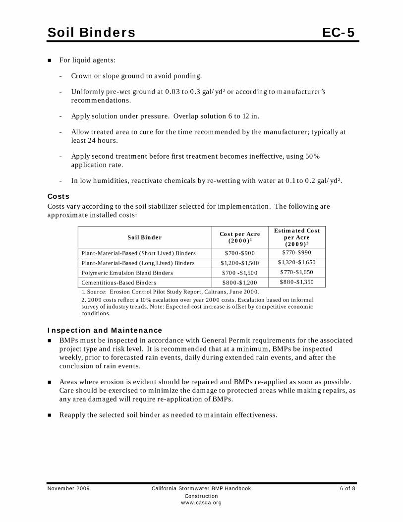
Costs Costs vary according to the soil stabilizer selected for implementation. The following are approximate installed costs:
Soil Binder Cost per Acre
(2000)1
Estimated Cost per Acre (2009)2
Plant-Material-Based (Short Lived) Binders $700-$900 $770-$990
Plant-Material-Based (Long Lived) Binders $1,200-$1,500 $1,320-$1,650
Polymeric Emulsion Blend Binders $700 -$1,500 $770-$1,650
Cementitious-Based Binders $800-$1,200 $880-$1,350
1. Source: Erosion Control Pilot Study Report, Caltrans, June 2000. 2. 2009 costs reflect a 10% escalation over year 2000 costs. Escalation based on informal survey of industry trends. Note: Expected cost increase is offset by competitive economic conditions.
Inspection and Maintenance
BMPs must be inspected in accordance with General Permit requirements for the associated project type and risk level. It is recommended that at a minimum, BMPs be inspected weekly, prior to forecasted rain events, daily during extended rain events, and after the conclusion of rain events.
Areas where erosion is evident should be repaired and BMPs re-applied as soon as possible. Care should be exercised to minimize the damage to protected areas while making repairs, as any area damaged will require re-application of BMPs.
Reapply the selected soil binder as needed to maintain effectiveness.

Soil Binders EC-5
November 2009 California Stormwater BMP Handbook 7 of 8
Construction
www.casqa.org
Table 1 Properties of Soil Binders for Erosion Control
Evaluation Criteria
Binder Type
Plant Material Based (Short
Lived)
Plant Material Based (Long
Lived)
Polymeric Emulsion Blends
Cementitious-Based Binders
Relative Cost Low Moderate to High
Low to High Low to Moderate
Resistance to Leaching High High Low to Moderate Moderate
Resistance to Abrasion Moderate Low Moderate to High Moderate to High
Longevity Short to Medium Medium Medium to Long Medium
Minimum Curing Time before Rain
9 to 18 hours 19 to 24 hours 0 to 24 hours 4 to 8 hours
Compatibility with Existing Vegetation
Good Poor Poor Poor
Mode of Degradation Biodegradable Biodegradable Photodegradable/
Chemically Degradable
Photodegradable/ Chemically Degradable
Labor Intensive No No No No
Specialized Application Equipment
Water Truck or Hydraulic Mulcher
Water Truck or Hydraulic Mulcher
Water Truck or Hydraulic Mulcher
Water Truck or Hydraulic Mulcher
Liquid/Powder Powder Liquid Liquid/Powder Powder
Surface Crusting Yes, but dissolves on rewetting
Yes Yes, but dissolves on rewetting
Yes
Clean Up Water Water Water Water
Erosion Control Application Rate
Varies (1) Varies (1) Varies (1) 4,000 to 12,000 lbs/acre
(1) See Implementation for specific rates.

Soil Binders EC-5
November 2009 California Stormwater BMP Handbook 8 of 8
Construction
www.casqa.org
References Erosion Control Pilot Study Report, State of California Department of Transportation (Caltrans), June 2000.
Manual of Standards of Erosion and Sediment Control Measures, Association of Bay Area Governments, May 1995.
Sedimentation and Erosion Control, An Inventory of Current Practices Draft, US EPA, April 1990.
Stormwater Quality Handbooks Construction Site Best Management Practices (BMPs) Manual, State of California Department of Transportation (Caltrans), March 2003.
Guidance Document: Soil Stabilization for Temporary Slopes, State of California Department of Transportation (Caltrans), November 1999.
Stormwater Management for Construction Activities, Developing Pollution Prevention Plans and Best Management Practices, EPA 832-R-92005; USEPA, April 1992.
Straw Mulch EC-6
November 2009 California Stormwater BMP Handbook 1 of 4
Construction
www.casqa.org
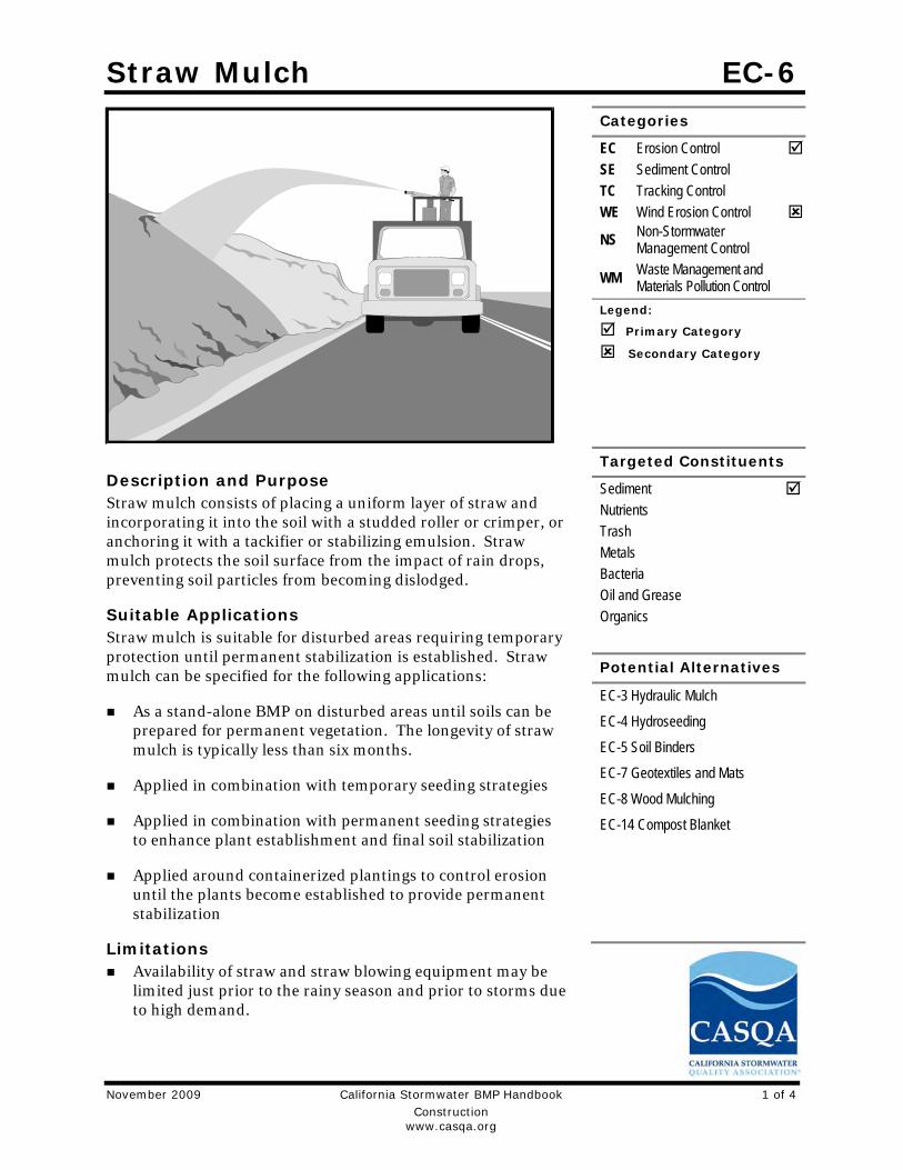
Description and Purpose Straw mulch consists of placing a uniform layer of straw and incorporating it into the soil with a studded roller or crimper, or anchoring it with a tackifier or stabilizing emulsion. Straw mulch protects the soil surface from the impact of rain drops, preventing soil particles from becoming dislodged.
Suitable Applications Straw mulch is suitable for disturbed areas requiring temporary protection until permanent stabilization is established. Straw mulch can be specified for the following applications:
As a stand-alone BMP on disturbed areas until soils can be prepared for permanent vegetation. The longevity of straw mulch is typically less than six months.
Applied in combination with temporary seeding strategies
Applied in combination with permanent seeding strategies to enhance plant establishment and final soil stabilization
Applied around containerized plantings to control erosion until the plants become established to provide permanent stabilization
Limitations Availability of straw and straw blowing equipment may be
limited just prior to the rainy season and prior to storms due to high demand.
Categories
EC Erosion Control SE Sediment Control TC Tracking Control WE Wind Erosion Control
NS Non-Stormwater Management Control
WM Waste Management and Materials Pollution Control
Legend:
Primary Category
Secondary Category
Targeted Constituents
Sediment Nutrients Trash Metals Bacteria Oil and Grease Organics
Potential Alternatives
EC-3 Hydraulic Mulch
EC-4 Hydroseeding
EC-5 Soil Binders
EC-7 Geotextiles and Mats
EC-8 Wood Mulching
EC-14 Compost Blanket

Straw Mulch EC-6
November 2009 California Stormwater BMP Handbook 2 of 4
Construction
www.casqa.org
There is a potential for introduction of weed seed and unwanted plant material if weed-free agricultural straw is not specified.
Straw mulch applied by hand is more time intensive and potentially costly.
Wind may limit application of straw and blow straw into undesired locations.
May have to be removed prior to permanent seeding or prior to further earthwork.
“Punching” of straw does not work in sandy soils, necessitating the use of tackifiers.
Potential fugitive dust control issues associated with straw applications can occur. Application of a stabilizing emulsion or a water stream at the same time straw is being blown can reduce this problem.
Use of plastic netting should be avoided in areas where wildlife may be entrapped and may be prohibited for projects in certain areas with sensitive wildlife species, especially reptiles and amphibians.
Implementation Straw should be derived from weed-free wheat, rice, or barley. Where required by the plans,
specifications, permits, or environmental documents, native grass straw should be used.
Use tackifier to anchor straw mulch to the soil on slopes.
Crimping, punch roller-type rollers, or track walking may also be used to incorporate straw mulch into the soil on slopes. Track walking can be used where other methods are impractical.
Avoid placing straw onto roads, sidewalks, drainage channels, sound walls, existing vegetation, etc.
Straw mulch with tackifier should not be applied during or immediately before rainfall.
Additional guidance on the comparison and selection of temporary slope stabilization methods is provided in Appendix F of the Handbook.
Application Procedures When using a tackifier to anchor the straw mulch, roughen embankment or fill areas by
rolling with a crimping or punching-type roller or by track walking before placing the straw mulch. Track walking should only be used where rolling is impractical.
Apply straw at a rate of between 3,000 and 4,000 lb/acre, either by machine or by hand distribution and provide 100% ground cover. A lighter application is used for flat surfaces and a heavier application is used for slopes.
Evenly distribute straw mulch on the soil surface.
Anchoring straw mulch to the soil surface by "punching" it into the soil mechanically (incorporating) can be used in lieu of a tackifier.

Straw Mulch EC-6
November 2009 California Stormwater BMP Handbook 3 of 4
Construction
www.casqa.org
Methods for holding the straw mulch in place depend upon the slope steepness, accessibility, soil conditions, and longevity.
- A tackifier acts to glue the straw fibers together and to the soil surface. The tackifier should be selected based on longevity and ability to hold the fibers in place. A tackifier is typically applied at a rate of 125 lb/acre. In windy conditions, the rates are typically 180 lb/acre.
- On very small areas, a spade or shovel can be used to punch in straw mulch.
- On slopes with soils that are stable enough and of sufficient gradient to safely support construction equipment without contributing to compaction and instability problems, straw can be "punched" into the ground using a knife blade roller or a straight bladed coulter, known commercially as a "crimper.”
Costs Average annual cost for installation and maintenance is included in the table below. Application by hand is more time intensive and potentially more costly.
BMP Unit Cost per Acre
Straw mulch, crimped or punched $2,458-$5,375
Straw mulch with tackifier $1,823-$4,802
Source: Caltrans Soil Stabilization BMP Research for Erosion and Sediment Controls, July 2007 Inspection and Maintenance
BMPs must be inspected in accordance with General Permit requirements for the associated project type and risk level. It is recommended that at a minimum, BMPs be inspected weekly, prior to forecasted rain events, daily during extended rain events, and after the conclusion of rain events.
Areas where erosion is evident should be repaired and BMPs re-applied as soon as possible. Care should be exercised to minimize the damage to protected areas while making repairs, as any area damaged will require re-application of BMPs.
The key consideration in inspection and maintenance is that the straw needs to last long enough to achieve erosion control objectives. Straw mulch as a stand-alone BMP is temporary and is not suited for long-term erosion control.
Maintain an unbroken, temporary mulched ground cover while disturbed soil areas are inactive. Repair any damaged ground cover and re-mulch exposed areas.
Reapplication of straw mulch and tackifier may be required to maintain effective soil stabilization over disturbed areas and slopes.

Straw Mulch EC-6
November 2009 California Stormwater BMP Handbook 4 of 4
Construction
www.casqa.org
References Soil Stabilization BMP Research for Erosion and Sediment Controls: Cost Survey Technical Memorandum, State of California Department of Transportation (Caltrans), July 2007.
Erosion and Sediment Control Manual, Oregon Department of Environmental Quality, February 2005.
Controlling Erosion of Construction Sites, Agricultural Information Bulletin #347, U.S. Department of Agriculture (USDA), Natural Resources Conservation Service (NRCS) (formerly Soil Conservation Service – SCS).
Guides for Erosion and Sediment Control in California, USDA Soils Conservation Service, January 1991.
Manual of Standards of Erosion and Sediment Control Measures, Association of Bay Area Governments, May 1995.
Soil Erosion by Water, Agricultural Information Bulletin #513, U.S. Department of Agriculture, Soil Conservation Service.
Stormwater Quality Handbooks Construction Site Best Management Practices (BMPs) Manual, State of California Department of Transportation (Caltrans), March 2003.
Stormwater Management of the Puget Sound Basin, Technical Manual, Publication #91-75, Washington State Department of Ecology, February 1992.
Water Quality Management Plan for the Lake Tahoe Region, Volume II, Handbook of Management Practices, Tahoe Regional Planning Agency, November 1988.

Geotextiles and Mats EC-7
November 2009 California Stormwater BMP Handbook 1 of 12
Construction
www.casqa.org
Description and Purpose Mattings, or Rolled Erosion Control Products (RECPs), can be made of natural or synthetic materials or a combination of the two. RECPs are used to cover the soil surface to reduce erosion from rainfall impact, hold soil in place, and absorb and hold moisture near the soil surface. Additionally, RECPs may be used to stabilize soils until vegetation is established or to reinforce non-woody surface vegetation.
Suitable Applications RECPs are typically applied on slopes where erosion hazard is high and vegetation will be slow to establish. Mattings are also used on stream banks, swales and other drainage channels where moving water at velocities between 3 ft/s and 6 ft/s are likely to cause scour and wash out new vegetation, and in areas where the soil surface is disturbed and where existing vegetation has been removed. RECPs may also be used when seeding cannot occur (e.g., late season construction and/or the arrival of an early rain season). RECPs should be considered when the soils are fine grained and potentially erosive. RECPs should be considered in the following situations.
Steep slopes, generally steeper than 3:1 (H:V)
Slopes where the erosion potential is high
Slopes and disturbed soils where mulch must be anchored
Disturbed areas where plants are slow to develop
Categories
EC Erosion Control SE Sediment Control TC Tracking Control WE Wind Erosion Control
NS Non-Stormwater Management Control
WM Waste Management and Materials Pollution Control
Legend:
Primary Category
Secondary Category
Targeted Constituents
Sediment Nutrients Trash Metals Bacteria Oil and Grease Organics
Potential Alternatives
EC-3 Hydraulic Mulch
EC-4 Hydroseeding

Geotextiles and Mats EC-7
November 2009 California Stormwater BMP Handbook 2 of 12
Construction
www.casqa.org
Channels with flows exceeding 3.3 ft/s
Channels to be vegetated
Stockpiles
Slopes adjacent to water bodies
Limitations RECP installed costs are generally higher than other erosion control BMPs, limiting their use
to areas where other BMPs are ineffective (e.g. channels, steep slopes).
RECPs may delay seed germination, due to reduction in soil temperature.
RECPs are generally not suitable for excessively rocky sites or areas where the final vegetation will be mowed (since staples and netting can catch in mowers). If a staple or pin cannot be driven into the soil because the underlying soil is too hard or rocky, then an alternative BMP should be selected.
If used for temporary erosion control, RECPs should be removed and disposed of prior to application of permanent soil stabilization measures.
The use of plastic should be limited to covering stockpiles or very small graded areas for short periods of time (such as through one imminent storm event) until more environmentally friendly measures, such as seeding and mulching, may be installed.
- Plastic sheeting is easily vandalized, easily torn, photodegradable, and must be disposed of at a landfill.
- Plastic sheeting results in 100% runoff, which may cause serious erosion problems in the areas receiving the increased flow.
RECPs may have limitations based on soil type, slope gradient, or channel flow rate; consult the manufacturer for proper selection.
Not suitable for areas that have foot traffic (tripping hazard) – e.g., pad areas around buildings under construction.
RECPs that incorporate a plastic netting (e.g. straw blanket typically uses a plastic netting to hold the straw in place) may not be suitable near known wildlife habitat. Wildlife can become trapped in the plastic netting.
RECPs may have limitations in extremely windy climates. However, when RECPs are properly trenched at the top and bottom and stapled in accordance with the manufacturer’s recommendations, problems with wind can be minimized.

Geotextiles and Mats EC-7
November 2009 California Stormwater BMP Handbook 3 of 12
Construction
www.casqa.org
Implementation Material Selection
Natural RECPs have been found to be effective where re-vegetation will be provided by re-seeding. The choice of material should be based on the size of area, side slopes, surface conditions such as hardness, moisture, weed growth, and availability of materials.
Additional guidance on the comparison and selection of temporary slope stabilization methods is provided in Appendix F of the Handbook.
The following natural and synthetic RECPs are commonly used:
Geotextiles Material can be a woven or a non-woven polypropylene fabric with minimum thickness of
0.06 in., minimum width of 12 ft and should have minimum tensile strength of 150 lbs (warp), 80 lbs (fill) in conformance with the requirements in ASTM Designation: D 4632. The permittivity of the fabric should be approximately 0.07 sec–1 in conformance with the requirements in ASTM Designation: D4491. The fabric should have an ultraviolet (UV) stability of 70 percent in conformance with the requirements in ASTM designation: D4355. Geotextile blankets must be secured in place with wire staples or sandbags and by keying into tops of slopes to prevent infiltration of surface waters under geotextile. Staples should be made of minimum 11 gauge steel wire and should be U-shaped with 8 in. legs and 2 in. crown.
Geotextiles may be reused if they are suitable for the use intended.
Plastic Covers Generally plastic sheeting should only be used as stockpile covering or for very small graded
areas for short periods of time (such as through one imminent storm event). If plastic sheeting must be used, choose a plastic that will withstand photo degradation.
Plastic sheeting should have a minimum thickness of 6 mils, and must be keyed in at the top of slope (when used as a temporary slope protection) and firmly held in place with sandbags or other weights placed no more than 10 ft apart. Seams are typically taped or weighted down their entire length, and there should be at least a 12 in. to 24 in. overlap of all seams. Edges should be embedded a minimum of 6 in. in soil (when used as a temporary slope protection).
All sheeting must be inspected periodically after installation and after significant rainstorms to check for erosion, undermining, and anchorage failure. Any failures must be repaired immediately. If washout or breakages occur, the material should be re-installed after repairing the damage to the slope.
Erosion Control Blankets/Mats Biodegradable RECPs are typically composed of jute fibers, curled wood fibers, straw,
coconut fiber, or a combination of these materials. In order for an RECP to be considered 100% biodegradable, the netting, sewing or adhesive system that holds the biodegradable mulch fibers together must also be biodegradable. See typical installation details at the end of this fact sheet.

Geotextiles and Mats EC-7
November 2009 California Stormwater BMP Handbook 4 of 12
Construction
www.casqa.org
- Jute is a natural fiber that is made into a yarn that is loosely woven into a biodegradable mesh. The performance of jute as a stand-alone RECP is low. Most other RECPs outperform jute as a temporary erosion control product and therefore jute is not commonly used. It is designed to be used in conjunction with vegetation. The material is supplied in rolled strips, which should be secured to the soil with U-shaped staples or stakes in accordance with manufacturers’ recommendations.
- Excelsior (curled wood fiber) blanket material should consist of machine produced mats of curled wood excelsior with 80 percent of the fiber 6 in. or longer. The excelsior blanket should be of consistent thickness. The wood fiber must be evenly distributed over the entire area of the blanket. The top surface of the blanket should be covered with a photodegradable extruded plastic mesh. The blanket should be smolder resistant without the use of chemical additives and should be non-toxic and non-injurious to plant and animal life. Excelsior blankets should be furnished in rolled strips, a minimum of 48 in. wide, and should have an average weight of 0.8 lb/yd2, ±10 percent, at the time of manufacture. Excelsior blankets must be secured in place with wire staples. Staples should be made of minimum 11 gauge steel wire and should be U-shaped with 8 in. legs and 2 in. crown.
- Straw blanket should be machine produced mats of straw with a lightweight biodegradable netting top layer. The straw should be attached to the netting with biodegradable thread or glue strips. The straw blanket should be of consistent thickness. The straw should be evenly distributed over the entire area of the blanket. Straw blanket should be furnished in rolled strips a minimum of 6.5 ft wide, a minimum of 80 ft long and a minimum of 0.5 lb/yd2. Straw blankets must be secured in place with wire staples. Staples should be made of minimum 11 gauge steel wire and should be U-shaped with 8 in. legs and 2 in. crown.
- Wood fiber blanket is composed of biodegradable fiber mulch with extruded plastic netting held together with adhesives. The material is designed to enhance re-vegetation. The material is furnished in rolled strips, which must be secured to the ground with U-shaped staples or stakes in accordance with manufacturers’ recommendations.
- Coconut fiber blanket should be a machine produced mat of 100 percent coconut fiber with biodegradable netting on the top and bottom. The coconut fiber should be attached to the netting with biodegradable thread or glue strips. The coconut fiber blanket should be of consistent thickness. The coconut fiber should be evenly distributed over the entire area of the blanket. Coconut fiber blanket should be furnished in rolled strips with a minimum of 6.5 ft wide, a minimum of 80 ft. long and a minimum of 0.5 lb/yd2. Coconut fiber blankets must be secured in place with wire staples. Staples should be made of minimum 11 gauge steel wire and should be U-shaped with 8 in. legs and 2 in. crown.
- Coconut fiber mesh is a thin permeable membrane made from coconut or corn fiber that is spun into a yarn and woven into a biodegradable mat. It is designed to be used in conjunction with vegetation and typically has longevity of several years. The material is supplied in rolled strips, which must be secured to the soil with U-shaped staples or stakes in accordance with manufacturers’ recommendations.
Geotextiles and Mats EC-7
November 2009 California Stormwater BMP Handbook 5 of 12
Construction
www.casqa.org
- Straw coconut fiber blanket should be machine produced mats of 70 percent straw and 30 percent coconut fiber with a biodegradable netting top layer and a biodegradable bottom net. The straw and coconut fiber should be attached to the netting with biodegradable thread or glue strips. The straw coconut fiber blanket should be of consistent thickness. The straw and coconut fiber should be evenly distributed over the entire area of the blanket. Straw coconut fiber blanket should be furnished in rolled strips a minimum of 6.5 ft wide, a minimum of 80 ft long and a minimum of 0.5 lb/yd2. Straw coconut fiber blankets must be secured in place with wire staples. Staples should be made of minimum 11 gauge steel wire and should be U-shaped with 8 in. legs and 2 in. crown.
Non-biodegradable RECPs are typically composed of polypropylene, polyethylene, nylon or other synthetic fibers. In some cases, a combination of biodegradable and synthetic fibers is used to construct the RECP. Netting used to hold these fibers together is typically non-biodegradable as well.
- Plastic netting is a lightweight biaxially oriented netting designed for securing loose mulches like straw or paper to soil surfaces to establish vegetation. The netting is photodegradable. The netting is supplied in rolled strips, which must be secured with U-shaped staples or stakes in accordance with manufacturers’ recommendations.
- Plastic mesh is an open weave geotextile that is composed of an extruded synthetic fiber woven into a mesh with an opening size of less than ¼ in. It is used with re-vegetation or may be used to secure loose fiber such as straw to the ground. The material is supplied in rolled strips, which must be secured to the soil with U-shaped staples or stakes in accordance with manufacturers’ recommendations.
- Synthetic fiber with netting is a mat that is composed of durable synthetic fibers treated to resist chemicals and ultraviolet light. The mat is a dense, three dimensional mesh of synthetic (typically polyolefin) fibers stitched between two polypropylene nets. The mats are designed to be re-vegetated and provide a permanent composite system of soil, roots, and geomatrix. The material is furnished in rolled strips, which must be secured with U-shaped staples or stakes in accordance with manufacturers’ recommendations.
- Bonded synthetic fibers consist of a three dimensional geomatrix nylon (or other synthetic) matting. Typically it has more than 90 percent open area, which facilitates root growth. It’s tough root reinforcing system anchors vegetation and protects against hydraulic lift and shear forces created by high volume discharges. It can be installed over prepared soil, followed by seeding into the mat. Once vegetated, it becomes an invisible composite system of soil, roots, and geomatrix. The material is furnished in rolled strips that must be secured with U-shaped staples or stakes in accordance with manufacturers’ recommendations.
- Combination synthetic and biodegradable RECPs consist of biodegradable fibers, such as wood fiber or coconut fiber, with a heavy polypropylene net stitched to the top and a high strength continuous filament geomatrix or net stitched to the bottom. The material is designed to enhance re-vegetation. The material is furnished in rolled strips,

Geotextiles and Mats EC-7
November 2009 California Stormwater BMP Handbook 6 of 12
Construction
www.casqa.org
which must be secured with U-shaped staples or stakes in accordance with manufacturers’ recommendations.
Site Preparation Proper soil preparation is essential to ensure complete contact of the RECP with the soil. Soil
Roughening is not recommended in areas where RECPs will be installed.
Grade and shape the area of installation.
Remove all rocks, clods, vegetation or other obstructions so that the installed blankets or mats will have complete, direct contact with the soil.
Prepare seedbed by loosening 2 to 3 in. of topsoil.
Seeding/Planting Seed the area before blanket installation for erosion control and re-vegetation. Seeding after mat installation is often specified for turf reinforcement application. When seeding prior to blanket installation, all areas disturbed during blanket installation must be re-seeded. Where soil filling is specified for turf reinforcement mats (TRMs), seed the matting and the entire disturbed area after installation and prior to filling the mat with soil.
Fertilize and seed in accordance with seeding specifications or other types of landscaping plans. The protective matting can be laid over areas where grass has been planted and the seedlings have emerged. Where vines or other ground covers are to be planted, lay the protective matting first and then plant through matting according to design of planting.
Check Slots Check slots shall be installed as required by the manufacturer.
Laying and Securing Matting Before laying the matting, all check slots should be installed and the seedbed should be
friable, made free from clods, rocks, and roots. The surface should be compacted and finished according to the requirements of the manufacturer’s recommendations.
Mechanical or manual lay down equipment should be capable of handling full rolls of fabric and laying the fabric smoothly without wrinkles or folds. The equipment should meet the fabric manufacturer’s recommendations or equivalent standards.
Anchoring U-shaped wire staples, metal geotextile stake pins, or triangular wooden stakes can be used
to anchor mats and blankets to the ground surface.
Wire staples should be made of minimum 11 gauge steel wire and should be U-shaped with 8 in. legs and 2 in. crown.
Metal stake pins should be 0.188 in. diameter steel with a 1.5 in. steel washer at the head of the pin, and 8 in. in length.
Wire staples and metal stakes should be driven flush to the soil surface.

Geotextiles and Mats EC-7
November 2009 California Stormwater BMP Handbook 7 of 12
Construction
www.casqa.org
Installation on Slopes Installation should be in accordance with the manufacturer's recommendations. In general, these will be as follows:
Begin at the top of the slope and anchor the blanket in a 6 in. deep by 6 in. wide trench. Backfill trench and tamp earth firmly.
Unroll blanket down slope in the direction of water flow.
Overlap the edges of adjacent parallel rolls 2 to 3 in. and staple every 3 ft (or greater, per manufacturer’s specifications).
When blankets must be spliced, place blankets end over end (shingle style) with 6 in. overlap. Staple through overlapped area, approximately 12 in. apart.
Lay blankets loosely and maintain direct contact with the soil. Do not stretch.
Staple blankets sufficiently to anchor blanket and maintain contact with the soil. Staples should be placed down the center and staggered with the staples placed along the edges. Steep slopes, 1:1 (H:V) to 2:1 (H:V), require a minimum of 2 staples/yd2. Moderate slopes, 2:1 (H:V) to 3:1 (H:V), require a minimum of 1 ½ staples/yd2. Check manufacturer’s specifications to determine if a higher density staple pattern is required.
Installation in Channels Installation should be in accordance with the manufacturer's recommendations. In general, these will be as follows:
Dig initial anchor trench 12 in. deep and 6 in. wide across the channel at the lower end of the project area.
Excavate intermittent check slots, 6 in. deep and 6 in. wide across the channel at 25 to 30 ft intervals along the channels.
Cut longitudinal channel anchor trenches 4 in. deep and 4 in. wide along each side of the installation to bury edges of matting, whenever possible extend matting 2 to 3 in. above the crest of the channel side slopes.
Beginning at the downstream end and in the center of the channel, place the initial end of the first roll in the anchor trench and secure with fastening devices at 12 in. intervals. Note: matting will initially be upside down in anchor trench.
In the same manner, position adjacent rolls in anchor trench, overlapping the preceding roll a minimum of 3 in.
Secure these initial ends of mats with anchors at 12 in. intervals, backfill and compact soil.
Unroll center strip of matting upstream. Stop at next check slot or terminal anchor trench. Unroll adjacent mats upstream in similar fashion, maintaining a 3 in. overlap.

Geotextiles and Mats EC-7
November 2009 California Stormwater BMP Handbook 8 of 12
Construction
www.casqa.org
Fold and secure all rolls of matting snugly into all transverse check slots. Lay mat in the bottom of the slot then fold back against itself. Anchor through both layers of mat at 12 in. intervals, then backfill and compact soil. Continue rolling all mat widths upstream to the next check slot or terminal anchor trench.
Alternate method for non-critical installations: Place two rows of anchors on 6 in. centers at 25 to 30 ft. intervals in lieu of excavated check slots.
Staple shingled lap spliced ends a minimum of 12 in. apart on 12 in. intervals.
Place edges of outside mats in previously excavated longitudinal slots; anchor using prescribed staple pattern, backfill, and compact soil.
Anchor, fill, and compact upstream end of mat in a 12 in. by 6 in. terminal trench.
Secure mat to ground surface using U-shaped wire staples, geotextile pins, or wooden stakes.
Seed and fill turf reinforcement matting with soil, if specified.
Soil Filling (if specified for turf reinforcement mat (TRM)) Installation should be in accordance with the manufacturer’s recommendations. Typical installation guidelines are as follows:
After seeding, spread and lightly rake ½-3/4 inches of fine topsoil into the TRM apertures to completely fill TRM thickness. Use backside of rake or other flat implement.
Alternatively, if allowed by product specifications, spread topsoil using lightweight loader, backhoe, or other power equipment. Avoid sharp turns with equipment.
Always consult the manufacturer's recommendations for installation.
Do not drive tracked or heavy equipment over mat.
Avoid any traffic over matting if loose or wet soil conditions exist.
Use shovels, rakes, or brooms for fine grading and touch up.
Smooth out soil filling just exposing top netting of mat.
Temporary Soil Stabilization Removal Temporary soil stabilization removed from the site of the work must be disposed of if
necessary.
Costs Installed costs can be relatively high compared to other BMPs. Approximate costs for installed materials are shown below:

Geotextiles and Mats EC-7
November 2009 California Stormwater BMP Handbook 9 of 12
Construction
www.casqa.org
Rolled Erosion Control Products Installed Cost per
Acre (2000)1 Estimated Cost
per Acre (2009)2
Biodegradable
Jute Mesh $6,000-$7,000 $6,600-$7,700
Curled Wood Fiber $8,000-$10,500 $8,800-$11,050
Straw $8,000-$10,500 $8,800-$11,050
Wood Fiber $8,000-$10,500 $8,800-$11,050
Coconut Fiber $13,000-$14,000 $14,300-$15,400
Coconut Fiber Mesh $30,000-$33,000 $33,000-$36,300
Straw Coconut Fiber $10,000-$12,000 $11,000-$13,200
Non-Biodegradable
Plastic Netting $2,000-$2,200 $2,200-$2,220
Plastic Mesh $3,000-$3,500 $3,300-$3,850
Synthetic Fiber with Netting $34,000-$40,000 $37,400-$44,000
Bonded Synthetic Fibers $45,000-$55,000 $49,500-$60,500
Combination with Biodegradable $30,000-$36,000 $33,000-$39,600
1. Source: Erosion Control Pilot Study Report, Caltrans, June 2000. 2. 2009 costs reflect a 10% escalation over year 2000 costs. Escalation based on informal survey of industry trends. Note: Expected cost increase is offset by competitive economic conditions.
Inspection and Maintenance RECPs must be inspected in accordance with General Permit requirements for the
associated project type and risk level. It is recommended that at a minimum, BMPs be inspected weekly, prior to forecasted rain events, daily during extended rain events, and after the conclusion of rain events.
Areas where erosion is evident shall be repaired and BMPs reapplied as soon as possible. Care should be exercised to minimize the damage to protected areas while making repairs, as any area damaged will require reapplication of BMPs.
If washout or breakage occurs, re-install the material after repairing the damage to the slope or channel.
Make sure matting is uniformly in contact with the soil.
Check that all the lap joints are secure.
Check that staples are flush with the ground.
References Erosion and Sediment Control Manual, Oregon Department of Environmental Quality, February 2005
Erosion Control Pilot Study Report, State of California Department of Transportation (Caltrans), June 2000.
Guides for Erosion and Sediment Controls in California, USDA Soils Conservation Service, January 1991.
Geotextiles and Mats EC-7
November 2009 California Stormwater BMP Handbook 10 of 12
Construction
www.casqa.org
National Management Measures to Control Nonpoint Source Pollution from Urban Areas, United States Environmental Protection Agency, 2002.
Stormwater Quality Handbooks Construction Site Best Management Practices (BMPs) Manual, State of California Department of Transportation (Caltrans), March 2003.
Guidance Document: Soil Stabilization for Temporary Slopes, State of California Department of Transportation (Caltrans), November 1999.
Stormwater Management of the Puget Sound Basin, Technical Manual, Publication #91-75, Washington State Department of Ecology, February 1992.
Water Quality Management Plan for The Lake Tahoe Region, Volume II, Handbook of Management Practices, Tahoe Regional Planning Agency, November 1988.

Geotextiles and Mats EC-7
November 2009 California Stormwater BMP Handbook 11 of 12
Construction
www.casqa.org

Geotextiles and Mats EC-7
November 2009 California Stormwater BMP Handbook 12 of 12
Construction
www.casqa.org

Earth Dikes and Drainage Swales EC-9 Categories
EC Erosion Control SE Sediment Control TC Tracking Control WE Wind Erosion Control
NS Non-Stormwater Management Control
WM Waste Management and Materials Pollution Control
Legend:
Primary Objective
Secondary Objective
Targeted Constituents
Sediment Nutrients Trash Metals Bacteria Oil and Grease Organics
Potential Alternatives
None
Description and Purpose An earth dike is a temporary berm or ridge of compacted soil used to divert runoff or channel water to a desired location. A drainage swale is a shaped and sloped depression in the soil surface used to convey runoff to a desired location. Earth dikes and drainage swales are used to divert off site runoff around the construction site, divert runoff from stabilized areas and disturbed areas, and direct runoff into sediment basins or traps.
Suitable Applications Earth dikes and drainage swales are suitable for use, individually or together, where runoff needs to be diverted from one area and conveyed to another.
Earth dikes and drainage swales may be used:
- To convey surface runoff down sloping land
- To intercept and divert runoff to avoid sheet flow over sloped surfaces
- To divert and direct runoff towards a stabilized watercourse, drainage pipe or channel
- To intercept runoff from paved surfaces
- Below steep grades where runoff begins to concentrate
- Along roadways and facility improvements subject to flood drainage
November 2009 California Stormwater BMP Handbook 1 of 7
Construction
www.casqa.org

Earth Dikes and Drainage Swales EC-9
- At the top of slopes to divert runon from adjacent or undisturbed slopes
- At bottom and mid slope locations to intercept sheet flow and convey concentrated flows
- Divert sediment laden runoff into sediment basins or traps
Limitations Dikes should not be used for drainage areas greater than 10 acres or along slopes greater than 10 percent. For larger areas more permanent drainage structures should be built. All drainage structures should be built in compliance with local municipal requirements.
Earth dikes may create more disturbed area on site and become barriers to construction equipment.
Earth dikes must be stabilized immediately, which adds cost and maintenance concerns.
Diverted stormwater may cause downstream flood damage.
Dikes should not be constructed of soils that may be easily eroded.
Regrading the site to remove the dike may add additional cost.
Temporary drains and swales or any other diversion of runoff should not adversely impact upstream or downstream properties.
Temporary drains and swales must conform to local floodplain management requirements.
Earth dikes/drainage swales are not suitable as sediment trapping devices.
It may be necessary to use other soil stabilization and sediment controls such as check dams, plastics, and blankets, to prevent scour and erosion in newly graded dikes, swales, and ditches.
Sediment accumulation, scour depressions, and/or persistent non-stormwater discharges can result in areas of standing water suitable for mosquito production in drainage swales.
Implementation The temporary earth dike is a berm or ridge of compacted soil, located in such a manner as to divert stormwater to a sediment trapping device or a stabilized outlet, thereby reducing the potential for erosion and offsite sedimentation. Earth dikes can also be used to divert runoff from off site and from undisturbed areas away from disturbed areas and to divert sheet flows away from unprotected slopes.
An earth dike does not itself control erosion or remove sediment from runoff. A dike prevents erosion by directing runoff to an erosion control device such as a sediment trap or directing runoff away from an erodible area. Temporary diversion dikes should not adversely impact adjacent properties and must conform to local floodplain management regulations, and should not be used in areas with slopes steeper than 10%.
Slopes that are formed during cut and fill operations should be protected from erosion by runoff. A combination of a temporary drainage swale and an earth dike at the top of a slope can divert
November 2009 California Stormwater BMP Handbook 2 of 7
Construction
www.casqa.org

Earth Dikes and Drainage Swales EC-9
runoff to a location where it can be brought to the bottom of the slope (see EC-11, Slope Drains). A combination dike and swale is easily constructed by a single pass of a bulldozer or grader and compacted by a second pass of the tracks or wheels over the ridge. Diversion structures should be installed when the site is initially graded and remain in place until post construction BMPs are installed and the slopes are stabilized.
Diversion practices concentrate surface runoff, increasing its velocity and erosive force. Thus, the flow out of the drain or swale must be directed onto a stabilized area or into a grade stabilization structure. If significant erosion will occur, a swale should be stabilized using vegetation, chemical treatment, rock rip-rap, matting, or other physical means of stabilization. Any drain or swale that conveys sediment laden runoff must be diverted into a sediment basin or trap before it is discharged from the site.
General Care must be applied to correctly size and locate earth dikes, drainage swales. Excessively
steep, unlined dikes, and swales are subject to erosion and gully formation.
Conveyances should be stabilized.
Use a lined ditch for high flow velocities.
Select flow velocity based on careful evaluation of the risks due to erosion of the measure, soil types, overtopping, flow backups, washout, and drainage flow patterns for each project site.
Compact any fills to prevent unequal settlement.
Do not divert runoff onto other property without securing written authorization from the property owner.
When possible, install and utilize permanent dikes, swales, and ditches early in the construction process.
Provide stabilized outlets.
Earth Dikes Temporary earth dikes are a practical, inexpensive BMP used to divert stormwater runoff. Temporary diversion dikes should be installed in the following manner:
All dikes should be compacted by earth moving equipment.
All dikes should have positive drainage to an outlet.
All dikes should have 2:1 or flatter side slopes, 18 in. minimum height, and a minimum top width of 24 in. Wide top widths and flat slopes are usually needed at crossings for construction traffic.
The outlet from the earth dike must function with a minimum of erosion. Runoff should be conveyed to a sediment trapping device such as a Sediment Trap (SE-3) or Sediment Basin
November 2009 California Stormwater BMP Handbook 3 of 7
Construction
www.casqa.org

Earth Dikes and Drainage Swales EC-9
(SE-2) when either the dike channel or the drainage area above the dike are not adequately stabilized.
Temporary stabilization may be achieved using seed and mulching for slopes less than 5% and either rip-rap or sod for slopes in excess of 5%. In either case, stabilization of the earth dike should be completed immediately after construction or prior to the first rain.
If riprap is used to stabilize the channel formed along the toe of the dike, the following typical specifications apply:
Channel Grade Riprap Stabilization
0.5-1.0% 4 in. Rock
1.1-2.0% 6 in. Rock
2.1-4.0% 8 in. Rock
4.1-5.0% 8 in. -12 in. Riprap
The stone riprap, recycled concrete, etc. used for stabilization should be pressed into the soil with construction equipment.
Filter cloth may be used to cover dikes in use for long periods.
Construction activity on the earth dike should be kept to a minimum.
Drainage Swales Drainage swales are only effective if they are properly installed. Swales are more effective than dikes because they tend to be more stable. The combination of a swale with a dike on the downhill side is the most cost effective diversion.
Standard engineering design criteria for small open channel and closed conveyance systems should be used (see the local drainage design manual). Unless local drainage design criteria state otherwise, drainage swales should be designed as follows:
No more than 5 acres may drain to a temporary drainage swale.
Place drainage swales above or below, not on, a cut or fill slope.
Swale bottom width should be at least 2 ft
Depth of the swale should be at least 18 in.
Side slopes should be 2:1 or flatter.
Drainage or swales should be laid at a grade of at least 1 percent, but not more than 15 percent.
The swale must not be overtopped by the peak discharge from a 10-year storm, irrespective of the design criteria stated above.
November 2009 California Stormwater BMP Handbook 4 of 7
Construction
www.casqa.org

Earth Dikes and Drainage Swales EC-9
Remove all trees, stumps, obstructions, and other objectionable material from the swale when it is built.
Compact any fill material along the path of the swale.
Stabilize all swales immediately. Seed and mulch swales at a slope of less than 5 percent, and use rip-rap or sod for swales with a slope between 5 and 15 percent. For temporary swales, geotextiles and mats (EC-7) may provide immediate stabilization.
Irrigation may be required to establish sufficient vegetation to prevent erosion.
Do not operate construction vehicles across a swale unless a stabilized crossing is provided.
Permanent drainage facilities must be designed by a professional engineer (see the local drainage design criteria for proper design).
At a minimum, the drainage swale should conform to predevelopment drainage patterns and capacities.
Construct the drainage swale with a positive grade to a stabilized outlet.
Provide erosion protection or energy dissipation measures if the flow out of the drainage swale can reach an erosive velocity.
Costs Cost ranges from $15 to $55 per ft for both earthwork and stabilization and depends on
availability of material, site location, and access.
Small dikes: $2.50 - $6.50/linear ft; Large dikes: $2.50/yd3.
The cost of a drainage swale increases with drainage area and slope. Typical swales for controlling internal erosion are inexpensive, as they are quickly formed during routine earthwork.
Inspection and Maintenance Inspect BMPs prior to forecast rain, daily during extended rain events, after rain events,
weekly during the rainy season, and at two-week intervals during the non-rainy season.
Inspect BMPs subject to non-stormwater discharges daily while non-stormwater discharges occur.
Inspect ditches and berms for washouts. Replace lost riprap, damaged linings or soil stabilizers as needed.
Inspect channel linings, embankments, and beds of ditches and berms for erosion and accumulation of debris and sediment. Remove debris and sediment and repair linings and embankments as needed.
Temporary conveyances should be completely removed as soon as the surrounding drainage area has been stabilized or at the completion of construction
November 2009 California Stormwater BMP Handbook 5 of 7
Construction
www.casqa.org

Earth Dikes and Drainage Swales EC-9
References Erosion and Sediment Control Handbook, S.J. Goldman, K. Jackson, T.A. Bursetynsky, P.E., McGraw Hill Book Company, 1986.
Manual of Standards of Erosion and Sediment Control Measures, Association of Bay Area Governments, May 1995.
Metzger, M.E. 2004. Managing mosquitoes in stormwater treatment devices. University of California Division of Agriculture and Natural Resources, Publication 8125. On-line: http:// anrcatalog.ucdavis.edu/pdf/8125.pdf
National Association of Home Builders (NAHB). Stormwater Runoff & Nonpoint Source Pollution Control Guide for Builders and Developers. National Association of Home Builders, Washington, D.C., 1995
National Management Measures to Control Nonpoint Source Pollution from Urban Areas, United States Environmental Protection Agency, 2002.
Southeastern Wisconsin Regional Planning Commission (SWRPC). Costs of Urban Nonpoint Source Water Pollution Control Measures. Technical Report No. 31. Southeastern Wisconsin Regional Planning Commission, Waukesha, WI. 1991
Stormwater Quality Handbooks Construction Site Best Management Practices (BMPs) Manual, State of California Department of Transportation (Caltrans), November 2000.
Stormwater Management of the Puget Sound Basin, Technical Manual, Publication #91-75, Washington State Department of Ecology, February 1992.
Water Quality Management Plan for the Lake Tahoe Region, Volume II, Handbook of Management Practices, Tahoe Regional Planning Agency, November 1988.
November 2009 California Stormwater BMP Handbook 6 of 7
Construction
www.casqa.org

Earth Dikes and Drainage Swales EC-9 Earth Dikes and Drainage Swales EC-9
November 2009 California Stormwater BMP Handbook 7 of 7 November 2009 California Stormwater BMP Handbook 7 of 7
Construction
www.casqa.org
Construction
www.casqa.org

Non-Vegetative Stabilization EC-16
November 2009 California Stormwater BMP Handbook 1 of 5
Construction
www.casqa.org
Description and Purpose Non-vegetative stabilization methods are used for temporary or permanent stabilization of areas prone to erosion and should be used only where vegetative options are not feasible; examples include:
Areas of vehicular or pedestrian traffic such as roads or paths;
Arid environments where vegetation would not provide timely ground coverage, or would require excessive irrigation;
Rocky substrate, infertile or droughty soils where vegetation would be difficult to establish; and
Areas where vegetation will not grow adequately within the construction time frame.
There are several non-vegetative stabilization methods and selection should be based on site-specific conditions.
Decomposed Granite (DG) is a permanent erosion protection method that consists of a layer of stabilized decomposed granite placed over an erodible surface.
Degradable Mulches of various types (see EC-3, EC-6, EC-8) can be used for temporary non-vegetative stabilization; examples include straw mulch, compost, wood chips or hydraulic mulch.
Geotextiles and Mats can be used for temporary non-vegetative stabilization (see EC-7). These BMPs are typically manufactured
Categories
EC Erosion Control SE Sediment Control TR Tracking Control WE Wind Erosion Control
NS Non-Stormwater Management Control
WM Waste Management and Materials Pollution Control
Legend:
Primary Category
Secondary Category
Targeted Constituents
Sediment Nutrients Trash Metals Bacteria Oil and Grease Organics
Potential Alternatives
None

Non-Vegetative Stabilization EC-16
November 2009 California Stormwater BMP Handbook 2 of 5
Construction
www.casqa.org
from degradable or synthetic materials and are designed and specified based on their functional longevity, i.e., how long they will persist and provide erosion protection. All geotextiles and mats should be replaced when they exceed their functional longevity or when permanent stabilization methods are instituted. Gravel Mulch is a non-degradable erosion control product that is composed of washed and screened coarse to very coarse gravel, 16 mm to 64 mm (0.6” - 2.5”), similar to an AASHTO No. 3 coarse aggregate.
Rock Slope Protection consists of utilizing large rock or rip-rap (4”- 24”) to stabilize slopes with a high erosion potential and those subject to scour along waterways.
Soil Binders can be used for temporary non-vegetative stabilization (see EC-5). The key to their use is functional longevity. In most cases, the soil binder will need to be routinely monitored and re-applied to maintain an erosion-resistant coverage.
Suitable Applications Non-vegetated stabilization methods are suitable for use on disturbed soil areas and on material stockpiles that need to be temporarily or permanently protected from erosion by water and wind. Non-vegetated stabilization should only be utilized when vegetation cannot be established in the required timeframe, due to soil or climactic conditions, or where vegetation may be a potential fire hazard.
Decomposed Granite (DG) and Gravel Mulch are suitable for use in areas where vegetation establishment is difficult, on flat surfaces, trails and pathways, and when used in conjunction with a stabilizer or tackifier, on shallow slopes (i.e., 10:1 [H:V]). DG and gravel can also be used on shallow rocky slopes where vegetation cannot be established for permanent erosion control.
Degradable Mulches can be used to cover and protect soil surfaces from erosion both in temporary and permanent applications. In many cases, the use of mulches by themselves requires routine inspection and re-application. See EC-3 Hydraulic Mulch, EC-6 Straw Mulch, EC-8 Wood Mulch, or EC-14 Compost Blankets for more information.
Geotextiles and Mats can be used as a temporary stand-alone soil stabilization method. Depending on material selection, geotextiles and mats can be a short-term (3 mos – 1 year) or long-term (1-2 years) temporary stabilization method. For more information on geotextiles and mats see EC-7 Geotextiles and Mats.
Rock Slope Protection can be used when the slopes are subject to scour or have a high erosion potential, such as slopes adjacent to flowing waterways or slopes subject to overflow from detention facilities (spillways).
Soil Binders can be used for temporary stabilization of stockpiles and disturbed areas not subject to heavy traffic. See EC-5 Soil Binders for more information.

Non-Vegetative Stabilization EC-16
November 2009 California Stormwater BMP Handbook 3 of 5
Construction
www.casqa.org
Limitations General
Refer to EC-3, EC-6, EC-8, and EC-14 for limitations on use of mulches. Refer to EC-7 for limitations on use of geotextiles and mats. Refer to EC-5 for limitations on use of Soil Binders.
Decomposed Granite Not available in some geographic regions.
If not tackified, material may be susceptible to erosion even on slight slopes (e.g., 30:1 [H:V]).
Installed costs may be more expensive than vegetative stabilization methods.
Gravel Mulch Availability is limited in some geographic regions.
If not properly screened and washed, can contain fine material that can erode and/or create dust problems.
If inadequately sized, material may be susceptible to erosion on sloped areas.
Pore spaces fill with dirt and debris over time; may provide a growing medium for weeds.
Rock Slope Protection Installation is labor intensive.
Installed costs can be significantly higher than vegetative stabilization methods.
Rounded stones may not be used on slopes greater than 2:1 [H:V].
Implementation General Non-vegetated stabilization should be used in accordance with the following general guidance:
Should be used in conjunction with other BMPs, including drainage, erosion controls and sediment controls.
Refer to EC-3, EC-6, EC-8, and EC-14 for implementation details for mulches. Refer to EC-7 for implementation details for geotextiles and mats. Refer to EC-5 for implementation details for soil binders.
Non-vegetated stabilization measures should be implemented as soon as the disturbance in the areas they are intended to protect has ceased.
Additional guidance on the comparison and selection of temporary slope stabilization methods is provided in Appendix F of the Handbook.
Decomposed Granite Stabilization If used for a road or path should be installed on a prepared base.

Non-Vegetative Stabilization EC-16
November 2009 California Stormwater BMP Handbook 4 of 5
Construction
www.casqa.org
Should be mixed with a stabilizer if used for roads or pathways, or on slope applications.
Though porous it is recommended to prevent standing water on or next to a decomposed granite road or pathway.
Gravel Mulch Should be sized based on slope, rainfall, and upgradient run-on conditions. Stone size
should be increased as potential for erosion increases (steeper slopes, high intensity rainfall).
If permanent, a weed control fabric should be placed prior to installation.
Should be installed at a minimum 2” depth.
Should completely cover all exposed surfaces.
Rock Slope Protection Rock slope protection installation should follow Caltrans Standard Specification 72-2: Rock
Slope Protection. Refer to the specification for rock conformity requirements and installation methods.
When using rock slope protection, rock size and installation method should be specified by an Engineer.
A geotextile fabric should be placed prior to installation.
Costs Costs are highly variable depending not only on technique chosen, but also on materials
chosen within specific techniques. In addition, availability of certain materials will vary by region/location, which will also affect the cost. Costs of mulches, geotextiles and mats, and soil binders are presented in their respective fact sheets. Costs for decomposed granite, gravel mulch stabilization and rock slope protection may be higher depending on location and availability of materials. Caltrans has provided an estimate for gravel mulch of $10 - $15/yd2 in flat areas and $11 - $23/yd2 on side slopes.
Inspection and Maintenance General
BMPs must be inspected in accordance with General Permit requirements for the associated project type and risk level. It is recommended that at a minimum, BMPs be inspected weekly, prior to forecasted rain events, daily during extended rain events, and after the conclusion of rain events.
For permanent installation, require inspection periodically and after major storm events to look for signs of erosion or damage to the stabilization.
All damage should be repaired immediately.
Refer to EC-3, EC-6, EC-8, and EC-14 for inspection and maintenance requirements for mulches. Refer to EC-7 for inspection and maintenance requirements for geotextiles and mats. Refer to EC-5 for inspection and maintenance requirements for soil binders.

Non-Vegetative Stabilization EC-16
November 2009 California Stormwater BMP Handbook 5 of 5
Construction
www.casqa.org
Decomposed Granite and Gravel Mulch Stabilization Rake out and add decomposed granite or gravel as needed to areas subject to rill erosion.
Inspect upgradient drainage controls and repair/modify as necessary.
Should remain stable under loose surface material. Any significant problem areas should be repaired to restore uniformity to the installation.
References Arid Zone Forestry: A Guide for Field Technicians. Food and Agriculture Organization of the United Nations, 1989.
Design of Roadside Channels with Flexible Linings, Hydraulic Engineering Circular Number 15, Third Edition, Federal Highway Administration, 2007.
Design Standards for Urban Infrastructure - Soft Landscape Design, Department of Territory and Municipal Services - Australian Capital Territory http://www.tams.act.gov.au/work/ standards_and_procedures/design_standards_for_urban_infrastructure
Erosion and Sediment Control Handbook: A Guide for Protection of State Waters through the use of Best Management Practices during Land Disturbing Activities, Tennessee Department of Environment and Conservation, 2002.
Gravel Mulch, Landscape Architecture Non-Standard Specification 10-2, California Department of Transportation (Caltrans), http://www.dot.ca.gov/hq/LandArch/roadside/detail-gm.htm
Maine Erosion and Sediment Control BMPs, DEPLW0588, Maine Department of Environmental Protection: Bureau of Land and Water Quality, 2003.
National Menu of Best Management Practices, US Environmental Protection Agency, 2006.
Standard Specification 72-2: Rock Slope Protection. California Department of Transportation, 2006.
Stormwater Quality Handbooks Construction Site Best Management Practices (BMPs) Manual, State of California Department of Transportation (Caltrans), March 2003.
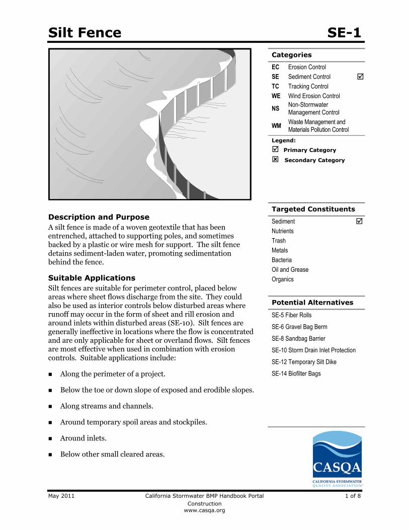
Silt Fence SE-1
May 2011 California Stormwater BMP Handbook Portal 1 of 8
Construction
www.casqa.org
Description and Purpose
A silt fence is made of a woven geotextile that has been entrenched, attached to supporting poles, and sometimes backed by a plastic or wire mesh for support. The silt fence detains sediment-laden water, promoting sedimentation behind the fence.
Suitable Applications
Silt fences are suitable for perimeter control, placed below areas where sheet flows discharge from the site. They could also be used as interior controls below disturbed areas where runoff may occur in the form of sheet and rill erosion and around inlets within disturbed areas (SE-10). Silt fences are generally ineffective in locations where the flow is concentrated and are only applicable for sheet or overland flows. Silt fences are most effective when used in combination with erosion controls. Suitable applications include:
Along the perimeter of a project.
Below the toe or down slope of exposed and erodible slopes.
Along streams and channels.
Around temporary spoil areas and stockpiles.
Around inlets.
Below other small cleared areas.
Categories
EC Erosion Control
SE Sediment Control
TC Tracking Control
WE Wind Erosion Control
NS Non-Stormwater Management Control
WM Waste Management and Materials Pollution Control
Legend:
Primary Category
Secondary Category
Targeted Constituents
Sediment
Nutrients
Trash
Metals
Bacteria
Oil and Grease
Organics
Potential Alternatives
SE-5 Fiber Rolls
SE-6 Gravel Bag Berm
SE-8 Sandbag Barrier
SE-10 Storm Drain Inlet Protection
SE-12 Temporary Silt Dike
SE-14 Biofilter Bags

Silt Fence SE-1
May 2011 California Stormwater BMP Handbook Portal 2 of 8
Construction
www.casqa.org
Limitations
Do not use in streams, channels, drain inlets, or anywhere flow is concentrated.
Do not use in locations where ponded water may cause a flooding hazard. Runoff typically ponds temporarily on the upstream side of silt fence.
Do not use silt fence to divert water flows or place across any contour line. Fences not constructed on a level contour, or fences used to divert flow will concentrate flows resulting in additional erosion and possibly overtopping or failure of the silt fence.
Improperly installed fences are subject to failure from undercutting, overtopping, or collapsing.
Not effective unless trenched and keyed in.
Not intended for use as mid-slope protection on slopes greater than 4:1 (H:V).
Do not use on slopes subject to creeping, slumping, or landslides.
Implementation
General
A silt fence is a temporary sediment barrier consisting of woven geotextile stretched across and attached to supporting posts, trenched-in, and, depending upon the strength of fabric used, supported with plastic or wire mesh fence. Silt fences trap sediment by intercepting and detaining small amounts of sediment-laden runoff from disturbed areas in order to promote sedimentation behind the fence.
The following layout and installation guidance can improve performance and should be followed:
Use principally in areas where sheet flow occurs.
Install along a level contour, so water does not pond more than 1.5 ft at any point along the silt fence.
The maximum length of slope draining to any point along the silt fence should be 200 ft or less.
The maximum slope perpendicular to the fence line should be 1:1.
Provide sufficient room for runoff to pond behind the fence and to allow sediment removal equipment to pass between the silt fence and toes of slopes or other obstructions. About 1200 ft2 of ponding area should be provided for every acre draining to the fence.
Turn the ends of the filter fence uphill to prevent stormwater from flowing around the fence.
Leave an undisturbed or stabilized area immediately down slope from the fence where feasible.

Silt Fence SE-1
May 2011 California Stormwater BMP Handbook Portal 3 of 8
Construction
www.casqa.org
Silt fences should remain in place until the disturbed area is permanently stabilized, after which, the silt fence should be removed and properly disposed.
Silt fence should be used in combination with erosion source controls up slope in order to provide the most effective sediment control.
Be aware of local regulations regarding the type and installation requirements of silt fence, which may differ from those presented in this fact sheet.
Design and Layout
The fence should be supported by a plastic or wire mesh if the fabric selected does not have sufficient strength and bursting strength characteristics for the planned application (as recommended by the fabric manufacturer). Woven geotextile material should contain ultraviolet inhibitors and stabilizers to provide a minimum of six months of expected usable construction life at a temperature range of 0 °F to 120 °F.
Layout in accordance with attached figures.
For slopes steeper than 2:1 (H:V) and that contain a high number of rocks or large dirt clods that tend to dislodge, it may be necessary to install additional protection immediately adjacent to the bottom of the slope, prior to installing silt fence. Additional protection may be a chain link fence or a cable fence.
For slopes adjacent to sensitive receiving waters or Environmentally Sensitive Areas (ESAs), silt fence should be used in conjunction with erosion control BMPs.
Standard vs. Heavy Duty Silt Fence
Standard Silt Fence
Generally applicable in cases where the slope of area draining to the silt fence is 4:1 (H:V) or less.
Used for shorter durations, typically 5 months or less
Area draining to fence produces moderate sediment loads.
Heavy Duty Silt Fence
Use is generally limited to 8 months or less.
Area draining to fence produces moderate sediment loads.
Heavy duty silt fence usually has 1 or more of the following characteristics, not possessed by standard silt fence.
o Fence fabric has higher tensile strength.
o Fabric is reinforced with wire backing or additional support.
o Posts are spaced closer than pre-manufactured, standard silt fence products.
o Posts are metal (steel or aluminum)
Materials
Standard Silt Fence
Silt fence material should be woven geotextile with a minimum width of 36 in. and a minimum tensile strength of 100 lb force. The fabric should conform to the requirements in ASTM designation D4632 and should have an integral reinforcement layer. The

Silt Fence SE-1
May 2011 California Stormwater BMP Handbook Portal 4 of 8
Construction
www.casqa.org
reinforcement layer should be a polypropylene, or equivalent, net provided by the manufacturer. The permittivity of the fabric should be between 0.1 sec-1 and 0.15 sec-1 in conformance with the requirements in ASTM designation D4491.
Wood stakes should be commercial quality lumber of the size and shape shown on the plans. Each stake should be free from decay, splits or cracks longer than the thickness of the stake or other defects that would weaken the stakes and cause the stakes to be structurally unsuitable.
Staples used to fasten the fence fabric to the stakes should be not less than 1.75 in. long and should be fabricated from 15 gauge or heavier wire. The wire used to fasten the tops of the stakes together when joining two sections of fence should be 9 gauge or heavier wire. Galvanizing of the fastening wire will not be required.
Heavy-Duty Silt Fence
Some silt fence has a wire backing to provide additional support, and there are products that may use prefabricated plastic holders for the silt fence and use metal posts or bar reinforcement instead of wood stakes. If bar reinforcement is used in lieu of wood stakes, use number four or greater bar. Provide end protection for any exposed bar reinforcement for health and safety purposes.
Installation Guidelines – Traditional Method
Silt fences are to be constructed on a level contour. Sufficient area should exist behind the fence for ponding to occur without flooding or overtopping the fence.
A trench should be excavated approximately 6 in. wide and 6 in. deep along the line of the proposed silt fence (trenches should not be excavated wider or deeper than necessary for proper silt fence installation).
Bottom of the silt fence should be keyed-in a minimum of 12 in.
Posts should be spaced a maximum of 6 ft apart and driven securely into the ground a minimum of 18 in. or 12 in. below the bottom of the trench.
When standard strength geotextile is used, a plastic or wire mesh support fence should be fastened securely to the upslope side of posts using heavy–duty wire staples at least 1 in. long. The mesh should extend into the trench.
When extra-strength geotextile and closer post spacing are used, the mesh support fence may be eliminated.
Woven geotextile should be purchased in a long roll, then cut to the length of the barrier. When joints are necessary, geotextile should be spliced together only at a support post, with a minimum 6 in. overlap and both ends securely fastened to the post.
The trench should be backfilled with native material and compacted.
Construct silt fences with a setback of at least 3 ft from the toe of a slope. Where, due to specific site conditions, a 3 ft setback is not available, the silt fence may be constructed at the

Silt Fence SE-1
May 2011 California Stormwater BMP Handbook Portal 5 of 8
Construction
www.casqa.org
toe of the slope, but should be constructed as far from the toe of the slope as practicable. Silt fences close to the toe of the slope will be less effective and more difficult to maintain.
Construct the length of each reach so that the change in base elevation along the reach does not exceed 1/3 the height of the barrier; in no case should the reach exceed 500 ft.
Cross barriers should be a minimum of 1/3 and a maximum of ½ the height of the linear barrier.
See typical installation details at the end of this fact sheet.
Installation Guidelines - Static Slicing Method
Static Slicing is defined as insertion of a narrow blade pulled behind a tractor, similar to a plow blade, at least 10 inches into the soil while at the same time pulling silt geotextile fabric into the ground through the opening created by the blade to the depth of the blade. Once the gerotextile is installed, the soil is compacted using tractor tires.
This method will not work with pre-fabricated, wire backed silt fence.
Benefits:
o Ease of installation (most often done with a 2 person crew). In addition, installation using static slicing has been found to be more efficient on slopes, in rocky soils, and in saturated soils.
o Minimal soil disturbance.
o Greater level of compaction along fence, leading to higher performance (i.e. greater sediment retention).
o Uniform installation.
o Less susceptible to undercutting/undermining.
Costs
It should be noted that costs vary greatly across regions due to available supplies and labor costs.
Average annual cost for installation using the traditional silt fence installation method (assumes 6 month useful life) is $7 per linear foot based on vendor research. Range of cost is $3.50 - $9.10 per linear foot.
In tests, the slicing method required 0.33 man hours per 100 linear feet, while the trenched based systems required as much as 1.01 man hours per linear foot.
Inspection and Maintenance
BMPs must be inspected in accordance with General Permit requirements for the associated project type and risk level. It is recommended that at a minimum, BMPs be inspected weekly, prior to forecasted rain events, daily during extended rain events, and after the conclusion of rain events.
Repair undercut silt fences.

Silt Fence SE-1
May 2011 California Stormwater BMP Handbook Portal 6 of 8
Construction
www.casqa.org
Repair or replace split, torn, slumping, or weathered fabric. The lifespan of silt fence fabric is generally 5 to 8 months.
Silt fences that are damaged and become unsuitable for the intended purpose should be removed from the site of work, disposed, and replaced with new silt fence barriers.
Sediment that accumulates in the BMP should be periodically removed in order to maintain BMP effectiveness. Sediment should be removed when the sediment accumulation reaches one-third of the barrier height.
Silt fences should be left in place until the upstream area is permanently stabilized. Until then, the silt fence should be inspected and maintained regularly.
Remove silt fence when upgradient areas are stabilized. Fill and compact post holes and anchor trench, remove sediment accumulation, grade fence alignment to blend with adjacent ground, and stabilize disturbed area.
References
Manual of Standards of Erosion and Sediment Control Measures, Association of Bay Area Governments, May 1995.
National Management Measures to Control Nonpoint Source Pollution from Urban Areas, United States Environmental Protection Agency, 2002.
Proposed Guidance Specifying Management Measures for Sources of Nonpoint Pollution in Coastal Waters, Work Group-Working Paper, USEPA, April 1992.
Sedimentation and Erosion Control Practices, and Inventory of Current Practices (Draft), UESPA, 1990.
Southeastern Wisconsin Regional Planning Commission (SWRPC). Costs of Urban Nonpoint Source Water Pollution Control Measures. Technical Report No. 31. Southeastern Wisconsin Regional Planning Commission, Waukesha, WI. 1991
Stormwater Quality Handbooks - Construction Site Best Management Practices (BMPs) Manual, State of California Department of Transportation (Caltrans), March 2003.
Stormwater Management Manual for The Puget Sound Basin, Washington State Department of Ecology, Public Review Draft, 1991.
U.S. Environmental Protection Agency (USEPA). Stormwater Management for Industrial Activities: Developing Pollution Prevention Plans and Best Management Practices. U.S. Environmental Protection Agency, Office of Water, Washington, DC, 1992.
Water Quality Management Plan for the Lake Tahoe Region, Volume II, Handbook of Management Practices, Tahoe Regional Planning Agency, November 1988.Soil Stabilization BMP Research for Erosion and Sediment Controls: Cost Survey Technical Memorandum, State of California Department of Transportation (Caltrans), July 2007.
Erosion and Sediment Control Manual, Oregon Department of Environmental Quality, February 2005.

Silt Fence SE-1
May 2011 California Stormwater BMP Handbook Portal 7 of 8
Construction
www.casqa.org
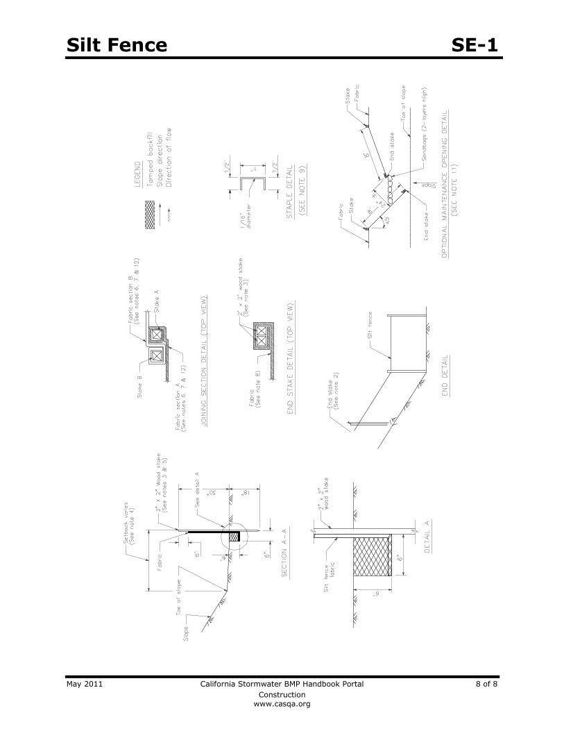
Silt Fence SE-1
May 2011 California Stormwater BMP Handbook Portal 8 of 8
Construction
www.casqa.org

Check Dams SE-4
May 2011 California Stormwater BMP Handbook Portal 1 of 7
Construction
www.casqa.org
Description and Purpose
A check dam is a small barrier constructed of rock, gravel bags, sandbags, fiber rolls, or other proprietary products, placed across a constructed swale or drainage ditch. Check dams reduce the effective slope of the channel, thereby reducing scour and channel erosion by reducing flow velocity and increasing residence time within the channel, allowing sediment to settle.
Suitable Applications
Check dams may be appropriate in the following situations:
To promote sedimentation behind the dam.
To prevent erosion by reducing the velocity of channel flow in small intermittent channels and temporary swales.
In small open channels that drain 10 acres or less.
In steep channels where stormwater runoff velocities exceed 5 ft/s.
During the establishment of grass linings in drainage ditches or channels.
In temporary ditches where the short length of service does not warrant establishment of erosion-resistant linings.
To act as a grade control structure.
Categories
EC Erosion Control
SE Sediment Control
TC Tracking Control
WE Wind Erosion Control
NS Non-Stormwater Management Control
WM Waste Management and Materials Pollution Control
Legend:
Primary Category
Secondary Category
Targeted Constituents
Sediment
Nutrients
Trash
Metals
Bacteria
Oil and Grease
Organics
Potential Alternatives
SE-5 Fiber Rolls
SE-6 Gravel Bag Berm
SE-8 Sandbag Barrier
SE-12 Temporary Silt Dike
SE-14 Biofilter Bags

Check Dams SE-4
May 2011 California Stormwater BMP Handbook Portal 2 of 7
Construction
www.casqa.org
Limitations
Not to be used in live streams or in channels with extended base flows.
Not appropriate in channels that drain areas greater than 10 acres.
Not appropriate in channels that are already grass-lined unless erosion potential or sediment-laden flow is expected, as installation may damage vegetation.
Require extensive maintenance following high velocity flows.
Promotes sediment trapping which can be re-suspended during subsequent storms or removal of the check dam.
Do not construct check dams with straw bales or silt fence.
Water suitable for mosquito production may stand behind check dams, particularly if subjected to daily non-stormwater discharges.
Implementation
General
Check dams reduce the effective slope and create small pools in swales and ditches that drain 10 acres or less. Using check dams to reduce channel slope reduces the velocity of stormwater flows, thus reducing erosion of the swale or ditch and promoting sedimentation. Thus, check dams are dual-purpose and serve an important role as erosion controls as well as as sediment controls. Note that use of 1-2 isolated check dams for sedimentation will likely result in little net removal of sediment because of the small detention time and probable scour during longer storms. Using a series of check dams will generally increase their effectiveness. A sediment trap (SE-3) may be placed immediately upstream of the check dam to increase sediment removal efficiency.
Design and Layout
Check dams work by decreasing the effective slope in ditches and swales. An important consequence of the reduced slope is a reduction in capacity of the ditch or swale. This reduction in capacity should be considered when using this BMP, as reduced capacity can result in overtopping of the ditch or swale and resultant consequences. In some cases, such as a “permanent” ditch or swale being constructed early and used as a “temporary” conveyance for construction flows, the ditch or swale may have sufficient capacity such that the temporary reduction in capacity due to check dams is acceptable. When check dams reduce capacities beyond acceptable limits, either:
Don’t use check dams. Consider alternative BMPs, or.
Increase the size of the ditch or swale to restore capacity.
Maximum slope and velocity reduction is achieved when the toe of the upstream dam is at the same elevation as the top of the downstream dam (see “Spacing Between Check Dams” detail at the end of this fact sheet). The center section of the dam should be lower than the edge sections (at least 6 inches), acting as a spillway, so that the check dam will direct flows to the center of

Check Dams SE-4
May 2011 California Stormwater BMP Handbook Portal 3 of 7
Construction
www.casqa.org
the ditch or swale (see “Typical Rock Check Dam” detail at the end of this fact sheet). Bypass or side-cutting can occur if a sufficient spillway is not provided in the center of the dam.
Check dams are usually constructed of rock, gravel bags, sandbags, and fiber rolls. A number of products can also be used as check dams (e.g. HDPE check dams, temporary silt dikes (SE-12)), and some of these products can be removed and reused. Check dams can also be constructed of logs or lumber, and have the advantage of a longer lifespan when compared to gravel bags, sandbags, and fiber rolls. Check dams should not be constructed from straw bales or silt fences, since concentrated flows quickly wash out these materials.
Rock check dams are usually constructed of 8 to 12 in. rock. The rock is placed either by hand or mechanically, but never just dumped into the channel. The dam should completely span the ditch or swale to prevent washout. The rock used should be large enough to stay in place given the expected design flow through the channel. It is recommended that abutments be extended 18 in. into the channel bank. Rock can be graded such that smaller diameter rock (e.g. 2-4 in) is located on the upstream side of larger rock (holding the smaller rock in place); increasing residence time.
Log check dams are usually constructed of 4 to 6 in. diameter logs, installed vertically. The logs should be embedded into the soil at least 18 in. Logs can be bolted or wired to vertical support logs that have been driven or buried into the soil.
See fiber rolls, SE-5, for installation of fiber roll check dams.
Gravel bag and sand bag check dams are constructed by stacking bags across the ditch or swale, shaped as shown in the drawings at the end of this fact sheet (see “Gravel Bag Check Dam” detail at the end of this fact sheet).
Manufactured products, such as temporary silt dikes (SE-12), should be installed in accordance with the manufacturer’s instructions. Installation typically requires anchoring or trenching of products, as well as regular maintenance to remove accumulated sediment and debris.
If grass is planted to stabilize the ditch or swale, the check dam should be removed when the grass has matured (unless the slope of the swales is greater than 4%).
The following guidance should be followed for the design and layout of check dams:
Install the first check dam approximately 16 ft from the outfall device and at regular intervals based on slope gradient and soil type.
Check dams should be placed at a distance and height to allow small pools to form between each check dam.
For multiple check dam installation, backwater from a downstream check dam should reach the toes of the upstream check dam.
A sediment trap provided immediately upstream of the check dam will help capture sediment. Due to the potential for this sediment to be resuspended in subsequent storms, the sediment trap should be cleaned following each storm event.

Check Dams SE-4
May 2011 California Stormwater BMP Handbook Portal 4 of 7
Construction
www.casqa.org
High flows (typically a 2-year storm or larger) should safely flow over the check dam without an increase in upstream flooding or damage to the check dam.
Where grass is used to line ditches, check dams should be removed when grass has matured sufficiently to protect the ditch or swale.
Materials
Rock used for check dams should typically be 8-12 in rock and be sufficiently sized to stay in place given expected design flows in the channel. Smaller diameter rock (e.g. 2 to 4 in) can be placed on the upstream side of larger rock to increase residence time.
Gravel bags used for check dams should conform to the requirements of SE-6, Gravel Bag Berms.
Sandbags used for check dams should conform to SE-8, Sandbag Barrier.
Fiber rolls used for check dams should conform to SE-5, Fiber Rolls.
Temporary silt dikes used for check dams should conform to SE-12, Temporary Silt Dikes.
Installation
Rock should be placed individually by hand or by mechanical methods (no dumping of rock) to achieve complete ditch or swale coverage.
Tightly abut bags and stack according to detail shown in the figure at the end of this section (pyramid approach). Gravel bags and sandbags should not be stacked any higher than 3 ft.
Upper rows or gravel and sand bags shall overlap joints in lower rows.
Fiber rolls should be trenched in, backfilled, and firmly staked in place.
Install along a level contour.
HDPE check dams, temporary silt dikes, and other manufactured products should be used and installed per manufacturer specifications.
Costs
Cost consists of labor costs if materials are readily available (such as gravel on-site). If material must be imported, costs will increase. For other material and installation costs, see SE-5, SE-6, SE-8, SE-12, and SE-14.
Inspection and Maintenance
BMPs must be inspected in accordance with General Permit requirements for the associated project type and risk level. It is recommended that at a minimum, BMPs be inspected weekly, prior to forecasted rain events, daily during extended rain events, and after the conclusion of rain events.
Replace missing rock, bags, rolls, etc. Replace bags or rolls that have degraded or have become damaged.

Check Dams SE-4
May 2011 California Stormwater BMP Handbook Portal 5 of 7
Construction
www.casqa.org
If the check dam is used as a sediment capture device, sediment that accumulates behind the BMP should be periodically removed in order to maintain BMP effectiveness. Sediment should be removed when the sediment accumulation reaches one-third of the barrier height.
If the check dam is used as a grade control structure, sediment removal is not required as long as the system continues to control the grade.
Inspect areas behind check dams for pools of standing water, especially if subjected to daily non-stormwater discharges.
Remove accumulated sediment prior to permanent seeding or soil stabilization.
Remove check dam and accumulated sediment when check dams are no longer needed.
References
Draft – Sedimentation and Erosion Control, and Inventory of Current Practices, USEPA, April 1990.
Manual of Standards of Erosion and Sediment Control Measures, Association of Bay Area Governments, May 1995.
Stormwater Quality Handbooks - Construction Site Best Management Practices (BMPs) Manual, State of California Department of Transportation (Caltrans), March 2003.
Stormwater Management of the Puget Sound Basin, Technical Manual, Publication #91-75, Washington State Department of Ecology, February 1992.
Erosion and Sediment Control Manual, Oregon Department of Environmental Quality, February 2005.
Metzger, M.E. 2004. Managing mosquitoes in stormwater treatment devices. University of California Division of Agriculture and Natural Resources, Publication 8125. On-line: http:// anrcatalog.ucdavis.edu/pdf/8125.pdf

Check Dams SE-4
May 2011 California Stormwater BMP Handbook Portal 6 of 7
Construction
www.casqa.org

Check Dams SE-4
May 2011 California Stormwater BMP Handbook Portal 7 of 7
Construction
www.casqa.org

Fiber Rolls SE-5
May 2011 California Stormwater BMP Handbook Portal 1 of 5
Construction
www.casqa.org
Description and Purpose
A fiber roll consists of straw, coir, or other biodegradable materials bound into a tight tubular roll wrapped by netting, which can be photodegradable or natural. Additionally, gravel core fiber rolls are available, which contain an imbedded ballast material such as gravel or sand for additional weight when staking the rolls are not feasible (such as use as inlet protection). When fiber rolls are placed at the toe and on the face of slopes along the contours, they intercept runoff, reduce its flow velocity, release the runoff as sheet flow, and provide removal of sediment from the runoff (through sedimentation). By interrupting the length of a slope, fiber rolls can also reduce sheet and rill erosion until vegetation is established.
Suitable Applications
Fiber rolls may be suitable:
Along the toe, top, face, and at grade breaks of exposed and erodible slopes to shorten slope length and spread runoff as sheet flow.
At the end of a downward slope where it transitions to a steeper slope.
Along the perimeter of a project.
As check dams in unlined ditches with minimal grade.
Down-slope of exposed soil areas.
At operational storm drains as a form of inlet protection.
Categories
EC Erosion Control
SE Sediment Control
TC Tracking Control
WE Wind Erosion Control
NS Non-Stormwater Management Control
WM Waste Management and Materials Pollution Control
Legend:
Primary Category
Secondary Category
Targeted Constituents
Sediment
Nutrients
Trash
Metals
Bacteria
Oil and Grease
Organics
Potential Alternatives
SE-1 Silt Fence
SE-6 Gravel Bag Berm
SE-8 Sandbag Barrier
SE-12 Temporary Silt Dike
SE-14 Biofilter Bags

Fiber Rolls SE-5
May 2011 California Stormwater BMP Handbook Portal 2 of 5
Construction
www.casqa.org
Around temporary stockpiles.
Limitations
Fiber rolls are not effective unless trenched in and staked.
Not intended for use in high flow situations.
Difficult to move once saturated.
If not properly staked and trenched in, fiber rolls could be transported by high flows.
Fiber rolls have a very limited sediment capture zone.
Fiber rolls should not be used on slopes subject to creep, slumping, or landslide.
Rolls typically function for 12-24 months depending upon local conditions.
Implementation
Fiber Roll Materials
Fiber rolls should be prefabricated.
Fiber rolls may come manufactured containing polyacrylamide (PAM), a flocculating agent within the roll. Fiber rolls impregnated with PAM provide additional sediment removal capabilities and should be used in areas with fine, clayey or silty soils to provide additional sediment removal capabilities. Monitoring may be required for these installations.
Fiber rolls are made from weed free rice straw, flax, or a similar agricultural material bound into a tight tubular roll by netting.
Typical fiber rolls vary in diameter from 9 in. to 20 in. Larger diameter rolls are available as well.
Installation
Locate fiber rolls on level contours spaced as follows:
Slope inclination of 4:1 (H:V) or flatter: Fiber rolls should be placed at a maximum interval of 20 ft.
Slope inclination between 4:1 and 2:1 (H:V): Fiber Rolls should be placed at a maximum interval of 15 ft. (a closer spacing is more effective).
Slope inclination 2:1 (H:V) or greater: Fiber Rolls should be placed at a maximum interval of 10 ft. (a closer spacing is more effective).
Prepare the slope before beginning installation.
Dig small trenches across the slope on the contour. The trench depth should be ¼ to 1/3 of the thickness of the roll, and the width should equal the roll diameter, in order to provide area to backfill the trench.

Fiber Rolls SE-5
May 2011 California Stormwater BMP Handbook Portal 3 of 5
Construction
www.casqa.org
It is critical that rolls are installed perpendicular to water movement, and parallel to the slope contour.
Start building trenches and installing rolls from the bottom of the slope and work up.
It is recommended that pilot holes be driven through the fiber roll. Use a straight bar to drive holes through the roll and into the soil for the wooden stakes.
Turn the ends of the fiber roll up slope to prevent runoff from going around the roll.
Stake fiber rolls into the trench.
Drive stakes at the end of each fiber roll and spaced 4 ft maximum on center.
Use wood stakes with a nominal classification of 0.75 by 0.75 in. and minimum length of 24 in.
If more than one fiber roll is placed in a row, the rolls should be overlapped, not abutted.
See typical fiber roll installation details at the end of this fact sheet.
Removal
Fiber rolls can be left in place or removed depending on the type of fiber roll and application (temporary vs. permanent installation). Typically, fiber rolls encased with plastic netting are used for a temporary application because the netting does not biodegrade. Fiber rolls used in a permanent application are typically encased with a biodegradeable material and are left in place. Removal of a fiber roll used in a permanent application can result in greater disturbance.
Temporary installations should only be removed when up gradient areas are stabilized per General Permit requirements, and/or pollutant sources no longer present a hazard. But, they should also be removed before vegetation becomes too mature so that the removal process does not disturb more soil and vegetation than is necessary.
Costs
Material costs for regular fiber rolls range from $20 - $30 per 25 ft roll.
Material costs for PAM impregnated fiber rolls range between 7.00-$9.00 per linear foot, based upon vendor research.
Inspection and Maintenance
BMPs must be inspected in accordance with General Permit requirements for the associated project type and risk level. It is recommended that at a minimum, BMPs be inspected weekly, prior to forecasted rain events, daily during extended rain events, and after the conclusion of rain events.
Repair or replace split, torn, unraveling, or slumping fiber rolls.
If the fiber roll is used as a sediment capture device, or as an erosion control device to maintain sheet flows, sediment that accumulates in the BMP should be periodically removed
Fiber Rolls SE-5
May 2011 California Stormwater BMP Handbook Portal 4 of 5
Construction
www.casqa.org
in order to maintain BMP effectiveness. Sediment should be removed when sediment accumulation reaches one-third the designated sediment storage depth.
If fiber rolls are used for erosion control, such as in a check dam, sediment removal should not be required as long as the system continues to control the grade. Sediment control BMPs will likely be required in conjunction with this type of application.
Repair any rills or gullies promptly.
References
Stormwater Quality Handbooks - Construction Site Best Management Practices (BMPs) Manual, State of California Department of Transportation (Caltrans), March 2003.
Erosion and Sediment Control Manual, Oregon Department of Environmental Quality, February 2005.

Fiber Rolls SE-5
May 2011 California Stormwater BMP Handbook Portal 5 of 5
Construction
www.casqa.org

Gravel Bag Berm SE-6
May 2011 California Stormwater BMP Handbook Portal 1 of 4
Construction
www.casqa.org
Description and Purpose
A gravel bag berm is a series of gravel-filled bags placed on a level contour to intercept sheet flows. Gravel bags pond sheet flow runoff, allowing sediment to settle out, and release runoff slowly as sheet flow, preventing erosion.
Suitable Applications
Gravel bag berms may be suitable:
As a linear sediment control measure:
Below the toe of slopes and erodible slopes
As sediment traps at culvert/pipe outlets
Below other small cleared areas
Along the perimeter of a site
Down slope of exposed soil areas
Around temporary stockpiles and spoil areas
Parallel to a roadway to keep sediment off paved areas
Along streams and channels
As a linear erosion control measure:
Along the face and at grade breaks of exposed and erodible slopes to shorten slope length and spread runoff as sheet flow.
Categories
EC Erosion Control
SE Sediment Control
TC Tracking Control
WE Wind Erosion Control
NS Non-Stormwater Management Control
WM Waste Management and Materials Pollution Control
Legend:
Primary Category
Secondary Category
Targeted Constituents
Sediment
Nutrients
Trash
Metals
Bacteria
Oil and Grease
Organics
Potential Alternatives
SE-1 Silt Fence
SE-5 Fiber Roll
SE-8 Sandbag Barrier
SE-12 Temporary Silt Dike
SE-14 Biofilter Bags

Gravel Bag Berm SE-6
May 2011 California Stormwater BMP Handbook Portal 2 of 4
Construction
www.casqa.org
At the top of slopes to divert runoff away from disturbed slopes.
As chevrons (small check dams) across mildly sloped construction roads. For use check dam use in channels, see SE-4, Check Dams.
Limitations
Gravel berms may be difficult to remove.
Removal problems limit their usefulness in landscaped areas.
Gravel bag berm may not be appropriate for drainage areas greater than 5 acres.
Runoff will pond upstream of the berm, possibly causing flooding if sufficient space does not exist.
Degraded gravel bags may rupture when removed, spilling contents.
Installation can be labor intensive.
Durability of gravel bags is somewhat limited and bags may need to be replaced when installation is required for longer than 6 months.
Easily damaged by construction equipment.
When used to detain concentrated flows, maintenance requirements increase.
Implementation
General
A gravel bag berm consists of a row of open graded gravel-filled bags placed on a level contour. When appropriately placed, a gravel bag berm intercepts and slows sheet flow runoff, causing temporary ponding. The temporary ponding allows sediment to settle. The open graded gravel in the bags is porous, which allows the ponded runoff to flow slowly through the bags, releasing the runoff as sheet flows. Gravel bag berms also interrupt the slope length and thereby reduce erosion by reducing the tendency of sheet flows to concentrate into rivulets, which erode rills, and ultimately gullies, into disturbed, sloped soils. Gravel bag berms are similar to sand bag barriers, but are more porous. Generally, gravel bag berms should be used in conjunction with temporary soil stabilization controls up slope to provide effective erosion and sediment control.
Design and Layout
Locate gravel bag berms on level contours.
When used for slope interruption, the following slope/sheet flow length combinations apply:
Slope inclination of 4:1 (H:V) or flatter: Gravel bags should be placed at a maximum interval of 20 ft, with the first row near the slope toe.
Slope inclination between 4:1 and 2:1 (H:V): Gravel bags should be placed at a maximum interval of 15 ft. (a closer spacing is more effective), with the first row near the slope toe.

Gravel Bag Berm SE-6
May 2011 California Stormwater BMP Handbook Portal 3 of 4
Construction
www.casqa.org
Slope inclination 2:1 (H:V) or greater: Gravel bags should be placed at a maximum interval of 10 ft. (a closer spacing is more effective), with the first row near the slope toe.
Turn the ends of the gravel bag barriers up slope to prevent runoff from going around the berm.
Allow sufficient space up slope from the gravel bag berm to allow ponding, and to provide room for sediment storage.
For installation near the toe of the slope, gravel bag barriers should be set back from the slope toe to facilitate cleaning. Where specific site conditions do not allow for a set-back, the gravel bag barrier may be constructed on the toe of the slope. To prevent flows behind the barrier, bags can be placed perpendicular to a berm to serve as cross barriers.
Drainage area should not exceed 5 acres.
In Non-Traffic Areas:
Height = 18 in. maximum
Top width = 24 in. minimum for three or more layer construction
Top width = 12 in. minimum for one or two layer construction
Side slopes = 2:1 (H:V) or flatter
In Construction Traffic Areas:
Height = 12 in. maximum
Top width = 24 in. minimum for three or more layer construction.
Top width = 12 in. minimum for one or two layer construction.
Side slopes = 2:1 (H:V) or flatter.
Butt ends of bags tightly.
On multiple row, or multiple layer construction, overlap butt joints of adjacent row and row beneath.
Use a pyramid approach when stacking bags.
Materials
Bag Material: Bags should be woven polypropylene, polyethylene or polyamide fabric or burlap, minimum unit weight of 4 ounces/yd2, Mullen burst strength exceeding 300 lb/in2 in conformance with the requirements in ASTM designation D3786, and ultraviolet stability exceeding 70% in conformance with the requirements in ASTM designation D4355.

Gravel Bag Berm SE-6
May 2011 California Stormwater BMP Handbook Portal 4 of 4
Construction
www.casqa.org
Bag Size: Each gravel-filled bag should have a length of 18 in., width of 12 in., thickness of 3 in., and mass of approximately 33 lbs. Bag dimensions are nominal, and may vary based on locally available materials.
Fill Material: Fill material should be 0.5 to 1 in. crushed rock, clean and free from clay, organic matter, and other deleterious material, or other suitable open graded, non-cohesive, porous gravel.
Costs
Material costs for gravel bags are average and are dependent upon material availability. $2.50-3.00 per filled gravel bag is standard based upon vendor research.
Inspection and Maintenance
BMPs must be inspected in accordance with General Permit requirements for the associated project type and risk level. It is recommended that at a minimum, BMPs be inspected weekly, prior to forecasted rain events, daily during extended rain events, and after the conclusion of rain events.
Gravel bags exposed to sunlight will need to be replaced every two to three months due to degrading of the bags.
Reshape or replace gravel bags as needed.
Repair washouts or other damage as needed.
Sediment that accumulates in the BMP should be periodically removed in order to maintain BMP effectiveness. Sediment should be removed when the sediment accumulation reaches one-third of the barrier height.
Remove gravel bag berms when no longer needed and recycle gravel fill whenever possible and properly dispose of bag material. Remove sediment accumulation and clean, re-grade, and stabilize the area.
References
Handbook of Steel Drainage and Highway Construction, American Iron and Steel Institute, 1983.
Stormwater Quality Handbooks - Construction Site Best Management Practices (BMPs) Manual, State of California Department of Transportation (Caltrans), March 2003.
Stormwater Pollution Plan Handbook, First Edition, State of California, Department of Transportation Division of New Technology, Materials and Research, October 1992.
Erosion and Sediment Control Manual, Oregon Department of Environmental Quality, February 2005.

Street Sweeping and Vacuuming SE-7
January 2011 California Stormwater BMP Handbook 1 of 2
Construction
www.casqa.org
Description and Purpose Street sweeping and vacuuming includes use of self-propelled and walk-behind equipment to remove sediment from streets and roadways, and to clean paved surfaces in preparation for final paving. Sweeping and vacuuming prevents sediment from the project site from entering storm drains or receiving waters.
Suitable Applications Sweeping and vacuuming are suitable anywhere sediment is tracked from the project site onto public or private paved streets and roads, typically at points of egress. Sweeping and vacuuming are also applicable during preparation of paved surfaces for final paving.
Limitations Sweeping and vacuuming may not be effective when sediment is wet or when tracked soil is caked (caked soil may need to be scraped loose).
Implementation Controlling the number of points where vehicles can leave
the site will allow sweeping and vacuuming efforts to be focused, and perhaps save money.
Inspect potential sediment tracking locations daily.
Visible sediment tracking should be swept or vacuumed on a daily basis.
Do not use kick brooms or sweeper attachments. These tend to spread the dirt rather than remove it.
Categories
EC Erosion Control
SE Sediment Control
TC Tracking Control
WE Wind Erosion Control
NS Non-Stormwater Management Control
WM Waste Management and Materials Pollution Control
Legend:
Primary Objective
Secondary Objective
Targeted Constituents
Sediment Nutrients Trash Metals Bacteria Oil and Grease Organics
Potential Alternatives
None

Street Sweeping and Vacuuming SE-7
January 2011 California Stormwater BMP Handbook 2 of 2
Construction
www.casqa.org
If not mixed with debris or trash, consider incorporating the removed sediment back into the project
Costs Rental rates for self-propelled sweepers vary depending on hopper size and duration of rental. Expect rental rates from $58/hour (3 yd3 hopper) to $88/hour (9 yd3
Inspection and Maintenance
hopper), plus operator costs. Hourly production rates vary with the amount of area to be swept and amount of sediment. Match the hopper size to the area and expect sediment load to minimize time spent dumping.
Inspect BMPs in accordance with General Permit requirements for the associated project type and risk level. It is recommended that at a minimum, BMPs be inspected weekly, prior to forecasted rain events, daily during extended rain events, and after the conclusion of rain events.
When actively in use, points of ingress and egress must be inspected daily.
When tracked or spilled sediment is observed outside the construction limits, it must be removed at least daily. More frequent removal, even continuous removal, may be required in some jurisdictions.
Be careful not to sweep up any unknown substance or any object that may be potentially hazardous.
Adjust brooms frequently; maximize efficiency of sweeping operations.
After sweeping is finished, properly dispose of sweeper wastes at an approved dumpsite.
References Stormwater Quality Handbooks - Construction Site Best Management Practices (BMPs) Manual, State of California Department of Transportation (Caltrans), November 2000.
Labor Surcharge and Equipment Rental Rates, State of California Department of Transportation (Caltrans), April 1, 2002 – March 31, 2003.

Storm Drain Inlet Protection SE-10
November 2009 California Stormwater BMP Handbook 1 of 10
Construction
www.casqa.org
Description and Purpose Storm drain inlet protection consists of a sediment filter or an impounding area in, around or upstream of a storm drain, drop inlet, or curb inlet. Storm drain inlet protection measures temporarily pond runoff before it enters the storm drain, allowing sediment to settle. Some filter configurations also remove sediment by filtering, but usually the ponding action results in the greatest sediment reduction. Temporary geotextile storm drain inserts attach underneath storm drain grates to capture and filter storm water.
Suitable Applications Every storm drain inlet receiving runoff from unstabilized or otherwise active work areas should be protected. Inlet protection should be used in conjunction with other erosion and sediment controls to prevent sediment-laden stormwater and non-stormwater discharges from entering the storm drain system.
Limitations Drainage area should not exceed 1 acre.
In general straw bales should not be used as inlet protection.
Requires an adequate area for water to pond without encroaching into portions of the roadway subject to traffic.
Categories
EC Erosion Control SE Sediment Control TC Tracking Control WE Wind Erosion Control
NS Non-Stormwater Management Control
WM Waste Management and Materials Pollution Control
Legend:
Primary Category
Secondary Category
Targeted Constituents
Sediment Nutrients Trash Metals Bacteria Oil and Grease Organics
Potential Alternatives
SE-1 Silt Fence
SE-5 Fiber Rolls
SE-6 Gravel Bag Berm
SE-8 Sandbag Barrier
SE-14 Biofilter Bags

Storm Drain Inlet Protection SE-10
November 2009 California Stormwater BMP Handbook 2 of 10
Construction
www.casqa.org
Sediment removal may be inadequate to prevent sediment discharges in high flow conditions or if runoff is heavily sediment laden. If high flow conditions are expected, use other onsite sediment trapping techniques in conjunction with inlet protection.
Frequent maintenance is required.
Limit drainage area to 1 acre maximum. For drainage areas larger than 1 acre, runoff should be routed to a sediment-trapping device designed for larger flows. See BMPs SE-2, Sediment Basin, and SE-3, Sediment Traps.
Excavated drop inlet sediment traps are appropriate where relatively heavy flows are expected, and overflow capability is needed.
Implementation General Inlet control measures presented in this handbook should not be used for inlets draining more than one acre. Runoff from larger disturbed areas should be first routed through SE-2, Sediment Basin or SE-3, Sediment Trap and/or used in conjunction with other drainage control, erosion control, and sediment control BMPs to protect the site. Different types of inlet protection are appropriate for different applications depending on site conditions and the type of inlet. Alternative methods are available in addition to the methods described/shown herein such as prefabricated inlet insert devices, or gutter protection devices.
Design and Layout Identify existing and planned storm drain inlets that have the potential to receive sediment-laden surface runoff. Determine if storm drain inlet protection is needed and which method to use.
The key to successful and safe use of storm drain inlet protection devices is to know where runoff that is directed toward the inlet to be protected will pond or be diverted as a result of installing the protection device.
- Determine the acceptable location and extent of ponding in the vicinity of the drain inlet. The acceptable location and extent of ponding will influence the type and design of the storm drain inlet protection device.
- Determine the extent of potential runoff diversion caused by the storm drain inlet protection device. Runoff ponded by inlet protection devices may flow around the device and towards the next downstream inlet. In some cases, this is acceptable; in other cases, serious erosion or downstream property damage can be caused by these diversions. The possibility of runoff diversions will influence whether or not storm drain inlet protection is suitable; and, if suitable, the type and design of the device.
The location and extent of ponding, and the extent of diversion, can usually be controlled through appropriate placement of the inlet protection device. In some cases, moving the inlet protection device a short distance upstream of the actual inlet can provide more efficient sediment control, limit ponding to desired areas, and prevent or control diversions.

Storm Drain Inlet Protection SE-10
November 2009 California Stormwater BMP Handbook 3 of 10
Construction
www.casqa.org
Six types of inlet protection are presented below. However, it is recognized that other effective methods and proprietary devices exist and may be selected.
- Silt Fence: Appropriate for drainage basins with less than a 5% slope, sheet flows, and flows under 0.5 cfs.
- Excavated Drop Inlet Sediment Trap: An excavated area around the inlet to trap sediment (SE-3).
- Gravel bag barrier: Used to create a small sediment trap upstream of inlets on sloped, paved streets. Appropriate for sheet flow or when concentrated flow may exceed 0.5 cfs, and where overtopping is required to prevent flooding.
- Block and Gravel Filter: Appropriate for flows greater than 0.5 cfs.
- Temporary Geotextile Storm drain Inserts: Different products provide different features. Refer to manufacturer details for targeted pollutants and additional features.
- Biofilter Bag Barrier: Used to create a small retention area upstream of inlets and can be located on pavement or soil. Biofilter bags slowly filter runoff allowing sediment to settle out. Appropriate for flows under 0.5 cfs.
Select the appropriate type of inlet protection and design as referred to or as described in this fact sheet.
Provide area around the inlet for water to pond without flooding structures and property.
Grates and spaces around all inlets should be sealed to prevent seepage of sediment-laden water.
Excavate sediment sumps (where needed) 1 to 2 ft with 2:1 side slopes around the inlet.
Installation DI Protection Type 1 - Silt Fence - Similar to constructing a silt fence; see BMP SE-1,
Silt Fence. Do not place fabric underneath the inlet grate since the collected sediment may fall into the drain inlet when the fabric is removed or replaced and water flow through the grate will be blocked resulting in flooding. See typical Type 1 installation details at the end of this fact sheet.
1. Excavate a trench approximately 6 in. wide and 6 in. deep along the line of the silt fence inlet protection device.
2. Place 2 in. by 2 in. wooden stakes around the perimeter of the inlet a maximum of 3 ft apart and drive them at least 18 in. into the ground or 12 in. below the bottom of the trench. The stakes should be at least 48 in.
3. Lay fabric along bottom of trench, up side of trench, and then up stakes. See SE-1, Silt Fence, for details. The maximum silt fence height around the inlet is 24 in.
4. Staple the filter fabric (for materials and specifications, see SE-1, Silt Fence) to wooden stakes. Use heavy-duty wire staples at least 1 in. in length.

Storm Drain Inlet Protection SE-10
November 2009 California Stormwater BMP Handbook 4 of 10
Construction
www.casqa.org
5. Backfill the trench with gravel or compacted earth all the way around.
DI Protection Type 2 - Excavated Drop Inlet Sediment Trap - Install filter fabric fence in accordance with DI Protection Type 1. Size excavated trap to provide a minimum storage capacity calculated at the rate 67 yd3/acre of drainage area. See typical Type 2 installation details at the end of this fact sheet.
DI Protection Type 3 - Gravel bag - Flow from a severe storm should not overtop the curb. In areas of high clay and silts, use filter fabric and gravel as additional filter media. Construct gravel bags in accordance with SE-6, Gravel Bag Berm. Gravel bags should be used due to their high permeability. See typical Type 3 installation details at the end of this fact sheet.
1. Construct on gently sloping street.
2. Leave room upstream of barrier for water to pond and sediment to settle.
3. Place several layers of gravel bags – overlapping the bags and packing them tightly together.
4. Leave gap of one bag on the top row to serve as a spillway. Flow from a severe storm (e.g., 10 year storm) should not overtop the curb.
DI Protection Type 4 – Block and Gravel Filter - Block and gravel filters are suitable for curb inlets commonly used in residential, commercial, and industrial construction. See typical Type 4 installation details at the end of this fact sheet.
1. Place hardware cloth or comparable wire mesh with 0.5 in. openings over the drop inlet so that the wire extends a minimum of 1 ft beyond each side of the inlet structure. If more than one strip is necessary, overlap the strips. Place woven geotextile over the wire mesh.
2. Place concrete blocks lengthwise on their sides in a single row around the perimeter of the inlet, so that the open ends face outward, not upward. The ends of adjacent blocks should abut. The height of the barrier can be varied, depending on design needs, by stacking combinations of blocks that are 4 in., 8 in., and 12 in. wide. The row of blocks should be at least 12 in. but no greater than 24 in. high.
3. Place wire mesh over the outside vertical face (open end) of the concrete blocks to prevent stone from being washed through the blocks. Use hardware cloth or comparable wire mesh with 0.5 in. opening.
4. Pile washed stone against the wire mesh to the top of the blocks. Use 0.75 to 3 in.
DI Protection Type 5 – Temporary Geotextile Insert (proprietary) – Many types of temporary inserts are available. Most inserts fit underneath the grate of a drop inlet or inside of a curb inlet and are fastened to the outside of the grate or curb. These inserts are removable and many can be cleaned and reused. Installation of these inserts differs between manufacturers. Please refer to manufacturer instruction for installation of proprietary devices.
Storm Drain Inlet Protection SE-10
November 2009 California Stormwater BMP Handbook 5 of 10
Construction
www.casqa.org
DI Protection Type 6 - Biofilter bags – Biofilter bags may be used as a substitute for gravel bags in low-flow situations. Biofilter bags should conform to specifications detailed in SE-14, Biofilter bags.
1. Construct in a gently sloping area.
2. Biofilter bags should be placed around inlets to intercept runoff flows.
3. All bag joints should overlap by 6 in.
4. Leave room upstream for water to pond and for sediment to settle out.
5. Stake bags to the ground as described in the following detail. Stakes may be omitted if bags are placed on a paved surface.
Costs Average annual cost for installation and maintenance of DI Type 1-4 and 6 (one year useful
life) is $200 per inlet.
Temporary geotextile inserts are proprietary and cost varies by region. These inserts can often be reused and may have greater than 1 year of use if maintained and kept undamaged. Average cost per insert ranges from $50-75 plus installation, but costs can exceed $100. This cost does not include maintenance.
Inspection and Maintenance BMPs must be inspected in accordance with General Permit requirements for the associated
project type and risk level. It is recommended that at a minimum, BMPs be inspected weekly, prior to forecasted rain events, daily during extended rain events, and after the conclusion of rain events.
Silt Fences. If the fabric becomes clogged, torn, or degrades, it should be replaced. Make sure the stakes are securely driven in the ground and are in good shape (i.e., not bent, cracked, or splintered, and are reasonably perpendicular to the ground). Replace damaged stakes. At a minimum, remove the sediment behind the fabric fence when accumulation reaches one-third the height of the fence or barrier height.
Gravel Filters. If the gravel becomes clogged with sediment, it should be carefully removed from the inlet and either cleaned or replaced. Since cleaning gravel at a construction site may be difficult, consider using the sediment-laden stone as fill material and put fresh stone around the inlet. Inspect bags for holes, gashes, and snags, and replace bags as needed. Check gravel bags for proper arrangement and displacement.
Sediment that accumulates in the BMP should be periodically removed in order to maintain BMP effectiveness. Sediment should be removed when the sediment accumulation reaches one-third of the barrier height.
Inspect and maintain temporary geotextile insert devices according to manufacturer’s specifications.
Remove storm drain inlet protection once the drainage area is stabilized.

Storm Drain Inlet Protection SE-10
November 2009 California Stormwater BMP Handbook 6 of 10
Construction
www.casqa.org
- Clean and regrade area around the inlet and clean the inside of the storm drain inlet, as it should be free of sediment and debris at the time of final inspection.
References Stormwater Quality Handbooks - Construction Site Best Management Practices (BMPs) Manual, State of California Department of Transportation (Caltrans), March 2003.
Stormwater Management Manual for The Puget Sound Basin, Washington State Department of Ecology, Public Review Draft, 1991.
Erosion and Sediment Control Manual, Oregon Department of Environmental Quality, February 2005.

Storm Drain Inlet Protection SE-10
November 2009 California Stormwater BMP Handbook 7 of 10
Construction
www.casqa.org

Storm Drain Inlet Protection SE-10
November 2009 California Stormwater BMP Handbook 8 of 10
Construction
www.casqa.org

Storm Drain Inlet Protection SE-10
November 2009 California Stormwater BMP Handbook 9 of 10
Construction
www.casqa.org

Storm Drain Inlet Protection SE-10
November 2009 California Stormwater BMP Handbook 10 of 10
Construction
www.casqa.org
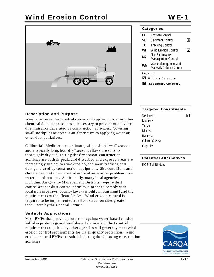
Wind Erosion Control WE-1
November 2009 California Stormwater BMP Handbook 1 of 5
Construction
www.casqa.org
Description and Purpose Wind erosion or dust control consists of applying water or other chemical dust suppressants as necessary to prevent or alleviate dust nuisance generated by construction activities. Covering small stockpiles or areas is an alternative to applying water or other dust palliatives.
California’s Mediterranean climate, with a short “wet” season and a typically long, hot “dry” season, allows the soils to thoroughly dry out. During the dry season, construction activities are at their peak, and disturbed and exposed areas are increasingly subject to wind erosion, sediment tracking and dust generated by construction equipment. Site conditions and climate can make dust control more of an erosion problem than water based erosion. Additionally, many local agencies, including Air Quality Management Districts, require dust control and/or dust control permits in order to comply with local nuisance laws, opacity laws (visibility impairment) and the requirements of the Clean Air Act. Wind erosion control is required to be implemented at all construction sites greater than 1 acre by the General Permit.
Suitable Applications Most BMPs that provide protection against water-based erosion will also protect against wind-based erosion and dust control requirements required by other agencies will generally meet wind erosion control requirements for water quality protection. Wind erosion control BMPs are suitable during the following construction activities:
Categories
EC Erosion Control SE Sediment Control TC Tracking Control WE Wind Erosion Control
NS Non-Stormwater Management Control
WM Waste Management and Materials Pollution Control
Legend:
Primary Category
Secondary Category
Targeted Constituents
Sediment Nutrients Trash Metals Bacteria Oil and Grease Organics
Potential Alternatives
EC-5 Soil Binders

Wind Erosion Control WE-1
November 2009 California Stormwater BMP Handbook 2 of 5
Construction
www.casqa.org
Construction vehicle traffic on unpaved roads
Drilling and blasting activities
Soils and debris storage piles
Batch drop from front-end loaders
Areas with unstabilized soil
Final grading/site stabilization
Limitations Watering prevents dust only for a short period (generally less than a few hours) and should
be applied daily (or more often) to be effective.
Over watering may cause erosion and track-out.
Oil or oil-treated subgrade should not be used for dust control because the oil may migrate into drainageways and/or seep into the soil.
Chemical dust suppression agents may have potential environmental impacts. Selected chemical dust control agents should be environmentally benign.
Effectiveness of controls depends on soil, temperature, humidity, wind velocity and traffic.
Chemical dust suppression agents should not be used within 100 feet of wetlands or water bodies.
Chemically treated subgrades may make the soil water repellant, interfering with long-term infiltration and the vegetation/re-vegetation of the site. Some chemical dust suppressants may be subject to freezing and may contain solvents and should be handled properly.
In compacted areas, watering and other liquid dust control measures may wash sediment or other constituents into the drainage system.
If the soil surface has minimal natural moisture, the affected area may need to be pre-wetted so that chemical dust control agents can uniformly penetrate the soil surface.
Implementation Dust Control Practices Dust control BMPs generally stabilize exposed surfaces and minimize activities that suspend or track dust particles. The following table presents dust control practices that can be applied to varying site conditions that could potentially cause dust. For heavily traveled and disturbed areas, wet suppression (watering), chemical dust suppression, gravel asphalt surfacing, temporary gravel construction entrances, equipment wash-out areas, and haul truck covers can be employed as dust control applications. Permanent or temporary vegetation and mulching can be employed for areas of occasional or no construction traffic. Preventive measures include minimizing surface areas to be disturbed, limiting onsite vehicle traffic to 15 mph or less, and controlling the number and activity of vehicles on a site at any given time.

Wind Erosion Control WE-1
November 2009 California Stormwater BMP Handbook 3 of 5
Construction
www.casqa.org
Chemical dust suppressants include: mulch and fiber based dust palliatives (e.g. paper mulch with gypsum binder), salts and brines (e.g. calcium chloride, magnesium chloride), non-petroleum based organics (e.g. vegetable oil, lignosulfonate), petroleum based organics (e.g. asphalt emulsion, dust oils, petroleum resins), synthetic polymers (e.g. polyvinyl acetate, vinyls, acrylic), clay additives (e.g. bentonite, montimorillonite) and electrochemical products (e.g. enzymes, ionic products).
Site Condition
Dust Control Practices
Permanent Vegetation Mulching
Wet Suppression (Watering)
Chemical Dust
Suppression
Gravel or
Asphalt
Temporary Gravel Construction
Entrances/Equipment Wash Down
Synthetic Covers
Minimize Extent of
Disturbed Area
Disturbed Areas not Subject to
Traffic
X X X X X X
Disturbed Areas
Subject to Traffic
X X X X X
Material Stockpiles
X X X X X
Demolition X X X
Clearing/ Excavation
X X X
Truck Traffic on Unpaved
Roads
X X X X X
Tracking X X
Additional preventive measures include:
Schedule construction activities to minimize exposed area (see EC-1, Scheduling).
Quickly treat exposed soils using water, mulching, chemical dust suppressants, or stone/gravel layering.
Identify and stabilize key access points prior to commencement of construction.
Minimize the impact of dust by anticipating the direction of prevailing winds.
Restrict construction traffic to stabilized roadways within the project site, as practicable.
Water should be applied by means of pressure-type distributors or pipelines equipped with a spray system or hoses and nozzles that will ensure even distribution.
All distribution equipment should be equipped with a positive means of shutoff.
Unless water is applied by means of pipelines, at least one mobile unit should be available at all times to apply water or dust palliative to the project.
If reclaimed waste water is used, the sources and discharge must meet California Department of Health Services water reclamation criteria and the Regional Water Quality

Wind Erosion Control WE-1
November 2009 California Stormwater BMP Handbook 4 of 5
Construction
www.casqa.org
Control Board (RWQCB) requirements. Non-potable water should not be conveyed in tanks or drain pipes that will be used to convey potable water and there should be no connection between potable and non-potable supplies. Non-potable tanks, pipes, and other conveyances should be marked, “NON-POTABLE WATER - DO NOT DRINK.”
Pave or chemically stabilize access points where unpaved traffic surfaces adjoin paved roads.
Provide covers for haul trucks transporting materials that contribute to dust.
Provide for rapid clean up of sediments deposited on paved roads. Furnish stabilized construction road entrances and wheel wash areas.
Stabilize inactive areas of construction sites using temporary vegetation or chemical stabilization methods.
For chemical stabilization, there are many products available for chemically stabilizing gravel roadways and stockpiles. If chemical stabilization is used, the chemicals should not create any adverse effects on stormwater, plant life, or groundwater and should meet all applicable regulatory requirements.
Costs Installation costs for water and chemical dust suppression vary based on the method used and the length of effectiveness. Annual costs may be high since some of these measures are effective for only a few hours to a few days.
Inspection and Maintenance Inspect and verify that activity-based BMPs are in place prior to the commencement of
associated activities.
BMPs must be inspected in accordance with General Permit requirements for the associated project type and risk level. It is recommended that at a minimum, BMPs be inspected weekly, prior to forecasted rain events, daily during extended rain events, and after the conclusion of rain events.
Check areas protected to ensure coverage.
Most water-based dust control measures require frequent application, often daily or even multiple times per day. Obtain vendor or independent information on longevity of chemical dust suppressants.
References Best Management Practices and Erosion Control Manual for Construction Sites, Flood Control District of Maricopa County, Arizona, September 1992.
California Air Pollution Control Laws, California Air Resources Board, updated annually.
Construction Manual, Chapter 4, Section 10, “Dust Control”; Section 17, “Watering”; and Section 18, “Dust Palliative”, California Department of Transportation (Caltrans), July 2001.

Wind Erosion Control WE-1
November 2009 California Stormwater BMP Handbook 5 of 5
Construction
www.casqa.org
Prospects for Attaining the State Ambient Air Quality Standards for Suspended Particulate Matter (PM10), Visibility Reducing Particles, Sulfates, Lead, and Hydrogen Sulfide, California Air Resources Board, April 1991.
Stormwater Quality Handbooks Construction Site Best Management Practices (BMPs) Manual, State of California Department of Transportation (Caltrans), March 2003.

Stabilized Construction Entrance/Exit TC-1
January 2011 California Stormwater BMP Handbook 1 of 6
Construction
www.casqa.org
Description and Purpose
A stabilized construction access is defined by a point of entrance/exit to a construction site that is stabilized to reduce the tracking of mud and dirt onto public roads by construction vehicles.
Suitable Applications
Use at construction sites:
Where dirt or mud can be tracked onto public roads.
Adjacent to water bodies.
Where poor soils are encountered.
Where dust is a problem during dry weather conditions.
Limitations
Entrances and exits require periodic top dressing with additional stones.
This BMP should be used in conjunction with street sweeping on adjacent public right of way.
Entrances and exits should be constructed on level ground only.
Stabilized construction entrances are rather expensive to construct and when a wash rack is included, a sediment trap of some kind must also be provided to collect wash water runoff.
Categories
EC Erosion Control
SE Sediment Control
TC Tracking Control
WE Wind Erosion Control
NS Non-Stormwater Management Control
WM Waste Management and Materials Pollution Control
Legend:
Primary Objective
Secondary Objective
Targeted Constituents
Sediment
Nutrients
Trash
Metals
Bacteria
Oil and Grease
Organics
Potential Alternatives
None

Stabilized Construction Entrance/Exit TC-1
January 2011 California Stormwater BMP Handbook 2 of 6
Construction
www.casqa.org
Implementation
General
A stabilized construction entrance is a pad of aggregate underlain with filter cloth located at any point where traffic will be entering or leaving a construction site to or from a public right of way, street, alley, sidewalk, or parking area. The purpose of a stabilized construction entrance is to reduce or eliminate the tracking of sediment onto public rights of way or streets. Reducing tracking of sediments and other pollutants onto paved roads helps prevent deposition of sediments into local storm drains and production of airborne dust.
Where traffic will be entering or leaving the construction site, a stabilized construction entrance should be used. NPDES permits require that appropriate measures be implemented to prevent tracking of sediments onto paved roadways, where a significant source of sediments is derived from mud and dirt carried out from unpaved roads and construction sites.
Stabilized construction entrances are moderately effective in removing sediment from equipment leaving a construction site. The entrance should be built on level ground. Advantages of the Stabilized Construction Entrance/Exit is that it does remove some sediment from equipment and serves to channel construction traffic in and out of the site at specified locations. Efficiency is greatly increased when a washing rack is included as part of a stabilized construction entrance/exit.
Design and Layout
Construct on level ground where possible.
Select 3 to 6 in. diameter stones.
Use minimum depth of stones of 12 in. or as recommended by soils engineer.
Construct length of 50 ft or maximum site will allow, and 10 ft minimum width or to accommodate traffic.
Rumble racks constructed of steel panels with ridges and installed in the stabilized entrance/exit will help remove additional sediment and to keep adjacent streets clean.
Provide ample turning radii as part of the entrance.
Limit the points of entrance/exit to the construction site.
Limit speed of vehicles to control dust.
Properly grade each construction entrance/exit to prevent runoff from leaving the construction site.
Route runoff from stabilized entrances/exits through a sediment trapping device before discharge.
Design stabilized entrance/exit to support heaviest vehicles and equipment that will use it.

Stabilized Construction Entrance/Exit TC-1
January 2011 California Stormwater BMP Handbook 3 of 6
Construction
www.casqa.org
Select construction access stabilization (aggregate, asphaltic concrete, concrete) based on longevity, required performance, and site conditions. Do not use asphalt concrete (AC) grindings for stabilized construction access/roadway.
If aggregate is selected, place crushed aggregate over geotextile fabric to at least 12 in. depth, or place aggregate to a depth recommended by a geotechnical engineer. A crushed aggregate greater than 3 in. but smaller than 6 in. should be used.
Designate combination or single purpose entrances and exits to the construction site.
Require that all employees, subcontractors, and suppliers utilize the stabilized construction access.
Implement SE-7, Street Sweeping and Vacuuming, as needed.
All exit locations intended to be used for more than a two-week period should have stabilized construction entrance/exit BMPs.
Inspection and Maintenance
Inspect and verify that activity–based BMPs are in place prior to the commencement of associated activities. While activities associated with the BMPs are under way, inspect BMPs in accordance with General Permit requirements for the associated project type and risk level. It is recommended that at a minimum, BMPs be inspected weekly, prior to forecasted rain events, daily during extended rain events, and after the conclusion of rain events.
Inspect local roads adjacent to the site daily. Sweep or vacuum to remove visible accumulated sediment.
Remove aggregate, separate and dispose of sediment if construction entrance/exit is clogged with sediment.
Keep all temporary roadway ditches clear.
Check for damage and repair as needed.
Replace gravel material when surface voids are visible.
Remove all sediment deposited on paved roadways within 24 hours.
Remove gravel and filter fabric at completion of construction
Costs
Average annual cost for installation and maintenance may vary from $1,200 to $4,800 each, averaging $2,400 per entrance. Costs will increase with addition of washing rack, and sediment trap. With wash rack, costs range from $1,200 - $6,000 each, averaging $3,600 per entrance.
References
Manual of Standards of Erosion and Sediment Control Measures, Association of Bay Area Governments, May 1995.

Stabilized Construction Entrance/Exit TC-1
January 2011 California Stormwater BMP Handbook 4 of 6
Construction
www.casqa.org
National Management Measures to Control Nonpoint Source Pollution from Urban Areas, USEPA Agency, 2002.
Proposed Guidance Specifying Management Measures for Sources of Nonpoint Pollution in Coastal Waters, Work Group Working Paper, USEPA, April 1992.
Stormwater Quality Handbooks Construction Site Best Management Practices (BMPs) Manual, State of California Department of Transportation (Caltrans), November 2000.
Stormwater Management of the Puget Sound Basin, Technical Manual, Publication #91-75, Washington State Department of Ecology, February 1992.
Virginia Erosion and Sedimentation Control Handbook, Virginia Department of Conservation and Recreation, Division of Soil and Water Conservation, 1991.
Guidance Specifying Management Measures for Nonpoint Pollution in Coastal Waters, EPA 840-B-9-002, USEPA, Office of Water, Washington, DC, 1993.
Water Quality Management Plan for the Lake Tahoe Region, Volume II, Handbook of Management Practices, Tahoe Regional Planning Agency, November 1988.

Stabilized Construction Entrance/Exit TC-1
January 2011 California Stormwater BMP Handbook 5 of 6
Construction
www.casqa.org
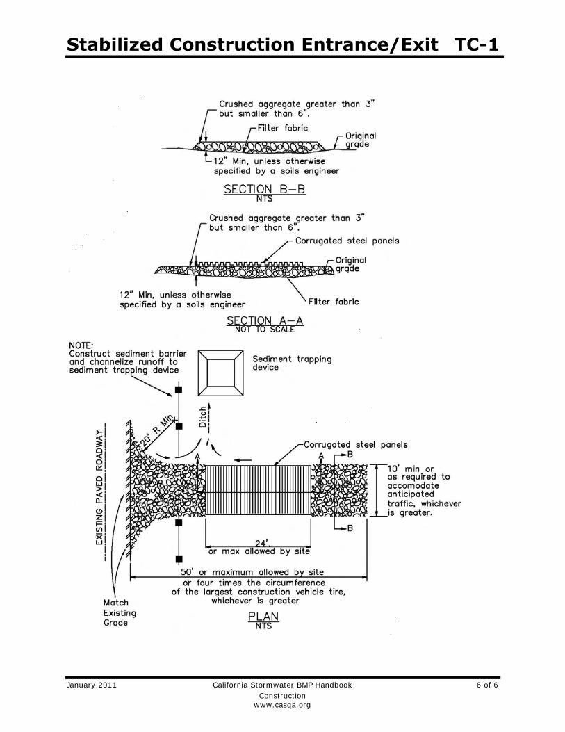
Stabilized Construction Entrance/Exit TC-1
January 2011 California Stormwater BMP Handbook 6 of 6
Construction
www.casqa.org

Stabilized Construction Roadway TC-2
January 2011 California Stormwater BMP Handbook 1 of 4
Construction
www.casqa.org
Description and Purpose Access roads, subdivision roads, parking areas, and other onsite vehicle transportation routes should be stabilized immediately after grading, and frequently maintained to prevent erosion and control dust.
Suitable Applications This BMP should be applied for the following conditions:
Temporary Construction Traffic:
Phased construction projects and offsite road access
Construction during wet weather
Construction roadways and detour roads:
Where mud tracking is a problem during wet weather
Where dust is a problem during dry weather
Adjacent to water bodies
Where poor soils are encountered
Limitations The roadway must be removed or paved when construction
is complete.
Certain chemical stabilization methods may cause stormwater or soil pollution and should not be used. See WE-1, Wind Erosion Control.
Categories
EC Erosion Control
SE Sediment Control
TC Tracking Control
WE Wind Erosion Control
NS Non-Stormwater Management Control
WM Waste Management and Materials Pollution Control
Legend:
Primary Objective
Secondary Objective
Targeted Constituents
Sediment Nutrients Trash Metals Bacteria Oil and Grease Organics
Potential Alternatives
None

Stabilized Construction Roadway TC-2
January 2011 California Stormwater BMP Handbook 2 of 4
Construction
www.casqa.org
Management of construction traffic is subject to air quality control measures. Contact the local air quality management agency.
Materials will likely need to be removed prior to final project grading and stabilization.
Use of this BMP may not be applicable to very short duration projects.
Implementation General Areas that are graded for construction vehicle transport and parking purposes are especially susceptible to erosion and dust. The exposed soil surface is continually disturbed, leaving no opportunity for vegetative stabilization. Such areas also tend to collect and transport runoff waters along their surfaces. During wet weather, they often become muddy quagmires that generate significant quantities of sediment that may pollute nearby streams or be transported offsite on the wheels of construction vehicles. Dirt roads can become so unstable during wet weather that they are virtually unusable.
Efficient construction road stabilization not only reduces onsite erosion but also can significantly speed onsite work, avoid instances of immobilized machinery and delivery vehicles, and generally improve site efficiency and working conditions during adverse weather
Installation/Application Criteria Permanent roads and parking areas should be paved as soon as possible after grading. As an alternative where construction will be phased, the early application of gravel or chemical stabilization may solve potential erosion and stability problems. Temporary gravel roadway should be considered during the rainy season and on slopes greater than 5%.
Temporary roads should follow the contour of the natural terrain to the maximum extent possible. Slope should not exceed 15%. Roadways should be carefully graded to drain transversely. Provide drainage swales on each side of the roadway in the case of a crowned section or one side in the case of a super elevated section. Simple gravel berms without a trench can also be used.
Installed inlets should be protected to prevent sediment laden water from entering the storm sewer system (SE-10, Storm Drain Inlet Protection). In addition, the following criteria should be considered.
Road should follow topographic contours to reduce erosion of the roadway.
The roadway slope should not exceed 15%.
Chemical stabilizers or water are usually required on gravel or dirt roads to prevent dust (WE-1, Wind Erosion Control).
Properly grade roadway to prevent runoff from leaving the construction site.
Design stabilized access to support heaviest vehicles and equipment that will use it.
Stabilized Construction Roadway TC-2
January 2011 California Stormwater BMP Handbook 3 of 4
Construction
www.casqa.org
Stabilize roadway using aggregate, asphalt concrete, or concrete based on longevity, required performance, and site conditions. The use of cold mix asphalt or asphalt concrete (AC) grindings for stabilized construction roadway is not allowed.
Coordinate materials with those used for stabilized construction entrance/exit points.
If aggregate is selected, place crushed aggregate over geotextile fabric to at least 12 in. depth. A crushed aggregate greater than 3 in. but smaller than 6 in. should be used.
Inspection and Maintenance Inspect and verify that activity–based BMPs are in place prior to the commencement of
associated activities. While activities associated with the BMP are under way, inspect BMPs in accordance with General Permit requirements for the associated project type and risk level. It is recommended that at a minimum, BMPs be inspected weekly, prior to forecasted rain events, daily during extended rain events, and after the conclusion of rain events.
Keep all temporary roadway ditches clear.
When no longer required, remove stabilized construction roadway and re-grade and repair slopes.
Periodically apply additional aggregate on gravel roads.
Active dirt construction roads are commonly watered three or more times per day during the dry season.
Costs Gravel construction roads are moderately expensive, but cost is often balanced by reductions in construction delay. No additional costs for dust control on construction roads should be required above that needed to meet local air quality requirements.
References Blueprint for a Clean Bay: Best Management Practices to Prevent Stormwater Pollution from Construction Related Activities; Santa Clara Valley Nonpoint Source Pollution Control Program, 1995.
Coastal Nonpoint Pollution Control Program; Program Development and Approval Guidance, Working Group, Working Paper; USEPA, April 1992.
Manual of Standards of Erosion and Sediment Control Measures, Association of Bay Area Governments, May 1995.
Stormwater Quality Handbooks Construction Site Best Management Practices (BMPs) Manual, State of California Department of Transportation (Caltrans), November 2000.
Stormwater Management for Construction Activities, Developing Pollution Prevention Plans and Best Management Practices, EPA 832-R-92005; USEPA, April 1992.
Stormwater Management of the Puget Sound Basin, Technical Manual, Publication #91-75, Washington State Department of Ecology, February 1992.

Stabilized Construction Roadway TC-2
January 2011 California Stormwater BMP Handbook 4 of 4
Construction
www.casqa.org
Virginia Erosion and Sedimentation Control Handbook, Virginia Department of Conservation and Recreation, Division of Soil and Water Conservation, 1991.
Water Quality Management Plan for the Lake Tahoe Region, Volume II, Handbook of Management Practices, Tahoe Regional Planning Agency, November 1988.