
SCHED Impact Analysis
54
2 Principles of SCHEDULE IMPACT ANALYSIS
Transcript of SCHED Impact Analysis

2
Principles
of
SCHEDULE IMPACT ANALYSIS

3
TABLE OF CONTENTS
1 INTRODUCTION 2 TERMINOLOGY 3 SCHEDULES
3.1 Baseline Schedule 3.2 Maintaining the Schedule of Record 3.3 Developing an As-Built Schedule
4 SCHEDULE IMPACTS 4.1 Understanding Schedule Impacts
4.1.1 Types of Schedule Impacts 4.1.1.1 Delays 4.1.1.2 Disruptions 4.1.1.3 Change 4.1.1.4 Suspensions 4.1.1.5 Termination
4.1.2 Causes of Schedule Impacts 4.1.2.1 Contractor 4.1.2.2 Owner 4.1.2.3 Third Party / Force Majeure
4.2 Classifying Schedule Impacts 4.2.1 Excusable, Non-compensable Delays (ED) 4.2.2 Excusable, Compensable Delays (ORD) 4.2.3 Non-Excusable, Non-Compensable Delays (CRD) 4.2.4 Non-Excusable, Compensable Delays (some ORD)
4.3 Concurrency 4.3.1 Concurrent Delays 4.3.2 Apportioning Concurrent Delays
5 SCHEDULE IMPACT ANALYSIS TECHNIQUES 5.1 Review of Methods
5.1.1 Retrospective Methods 5.1.1.1 Global Impact Approach 5.1.1.2 Net Impact Approach 5.1.1.3 Adjusted As-Planned CPM Approach 5.1.1.4 Adjusted As-Built CPM Approach 5.1.1.5 Collapsed As-Built (But-for) Schedule Approach
5.1.2 Contemporaneous Methods 5.1.2.1 Impacted Updated CPM (Veterans Administration) Approach 5.1.2.2 Modification Impact Analysis (U.S. Army Corps of Engineers’) Approach 5.1.2.3 Time Impact Analysis Approach
5.2 Comparison of Methods 6 SUMMARY AND RECOMMENDATIONS 7 REFERENCES

4
LIST OF FIGURES
Figure 1: Overview of Schedule Impact Analysis .............................................................. 5 Figure 2: Schedule of Record Flowchart .......................................................................... 12 Figure 3: Sources of Information used to Develop As-Built Schedule ............................ 14 Figure 4: Classification of Delays..................................................................................... 22 Figure 5: As-Planned CPM Network for Drainage Structure Example............................ 25 Figure 6: As-Built CPM Network for Drainage Structure Example................................. 25
Figure 7: Drainage Structure Example Delays ................................................................. 25 Figure 8: Concurrent Delays ............................................................................................. 27 Figure 9: Apportioning Concurrent Delays ...................................................................... 29 Figure 10: Schedule Impact Analysis Techniques Comparison ....................................... 31 Figure 11: Train Schedule Example – TIA Techniques ................................................... 32 Figure 12: Drainage Structure Example Bar Chart and Delays ........................................ 35 Figure 13: Diagram Key ................................................................................................... 36 Figure 14: Global Impact Approach ................................................................................. 37 Figure 15: Net Impact Approach ...................................................................................... 38 Figure 16: Adjusted As-Planned CPM Approach............................................................. 39 Figure 17: Adjusted As-Built CPM Approach ................................................................. 41 Figure 18: Collapsed As-Built Schedule (But-for) Approach .......................................... 43
Figure 19: Impacted Updated CPM (Veterans Administration) Approach ...................... 45 Figure 20: Modification Impact Analysis (U.S. Army Corps of Engineers’) Approach .. 48
Figure 21: Time Impact Analysis Approach..................................................................... 51 Figure 22: Results of TIA Techniques for Drainage Structure Example.......................... 52

5
1 INTRODUCTION
From a scheduling standpoint, the goal of every project is to be delivered on time and within
budget, with desired functionality and acceptable quality level. In an ideal world, projects follow
early starts and early finishes, float is not consumed, deadlines are met, the contractor never
files claims for time extension, and the owner never assesses liquidated damages. Such a
scenario rarely exists on construction projects – events occur that potentially affect the planned
completion of work, requiring a need to evaluate the impending impact of this event on the
project schedule.
Schedule impact analysis is defined as the process of quantifying and apportioning the
effect of delay or change on a project schedule. Although not all events that differ from the
planned schedule of work will result in a schedule impact, this document is written to identify
events that will have an impact, show what that impact is, and assign responsibility for the
impact. Figure 1 summarizes the key elements of a schedule impact, in bar chart format. The
As-Planned (Baseline) schedule includes the entire planned duration of the project, while the
As-Built to Date represents the duration of work that has been completed to the present time.
At this “present time”, it is realized that the project may not finish on time, and the owner
wants to know when the project will be delivered. Events have taken place, which are
determined to impact the remaining schedule, as shown by the To Build bar. As stated
before, a schedule impact analysis is the process of quantifying and apportioning the effect of
this delay. The Total Impact quantifies the effect that these events have had on the projected
completion date of the project, and it is now time to apportion responsibility for why the
project will be
delivered late.
Total Impact
As-Planned (Baseline)
As-Built to Date
Apportioning Responsibility Mine Yours
To Build
Figure 1: Overview of Schedule Impact Analysis

6
Without implementation of a proper schedule impact technique, it is difficult, if not
impossible, to accurately quantify and apportion the impact that a delay or change has on the
completion of a project. Too often are time extensions and damages assessed based on
simplistic measures, such as robotically using the total duration of a delay for granting the
number of days for a time extension, rather than considering all influences on the project and
its schedule and addressing the delay using a method that utilizes a critical path analysis. CPM
scheduling forms the backbone of both this document and of effective schedule impact analysis
techniques. The critical path method’s ability to accurately represent living, growing projects
are what makes it ideal for determining how an event may potentially impact project
completion.
This report emphasizes how to identify and classify potential schedule impacts, as well as
how to determine what, if any effect they have on the project completion date. In Chapter 3,
discussion of the key elements of baseline schedules, updated and revised schedules of record,
and as-built schedules show the reader the importance of properly maintaining these documents
in a manner that will be most beneficial when claims are filed for time extensions or damages.
Maintaining schedule documents are essential to any successful claim or defense against
claim, as courts have upheld that regularly updated and maintained schedules most
accurately portray the project in its completion. Chapter 4 discusses the different types and
causes of schedule impacts. Whether caused by the owner, contractor, or another source out
of their control, there are different types of events that may impact the schedule. After events
are identified, they are then classified into categories of excusable/non-excusable and
compensable/non-compensable delays. Doing so prepares the delays for a schedule impact
analysis. Eight different schedule impact analysis techniques are reviewed in Chapter 5, which
use a common, basic example to show how each method is implemented. Techniques vary in
their use of CPM schedules, utilizing as-planned and as-built schedules in both retrospective and
contemporaneous manners. A comparison of methods will give insight into the results of the
analysis, followed by recommendations of the most accurate schedule impact techniques,
discussed in Chapter 6, which show clear advantages to using certain techniques instead of
others.

7
The intended audience for this report is executives and managers who want an overview
of the principles of schedule impact analysis and how they are applied, in order to have a better
understanding of information presented by schedule analysts. This document is not intended
to prepare the reader to perform a schedule impact analysis of an actual project, but to
educate on the fundamentals of schedule impacts and their use in accurately determining the
potential effect a delay or change has on the schedule and on timely project completion.
2 TERMINOLOGY
This chapter will define key terms that are used throughout the report. It is assumed
that the reader has knowledge of the principles of planning and scheduling. If this is not the
case, a precursor to this report is the technical report “An Introduction to the Management
Principles of Scheduling” by Brian Munoz, VDOT-VT Partnership for Project Scheduling. The
following definitions are identified by the VDOT-VT Partnership for Project Scheduling, with
reference to the following sources: Bartholomew
2002, Bramble et al. 1990, and Parvin 1993.
Act of God – a natural occurrence caused directly and exclusively by natural forces without any human intervention, which could not have been reasonably foreseen or prevented by the contractor or any other party to the contract
Adjusted As-Built – a retrospective schedule impact analysis technique that uses a one time,
after-the-fact insertion of owner and excusable delays into the as-built schedule to quantify global impact
Adjusted As-Planned – a retrospective schedule impact analysis technique in which delays are
incorporated into the original CPM without regard to actual progress or historical work activity data, in order to quantify global impact
As-Built Schedule – an accurate historical representation of the actual sequence of construction
and how it was completed
Baseline (As-Planned) Schedule – the target construction schedule based on the contractor’s original understanding of the project and used as the standard by which progress is measured
Cardinal Change – a change (either directed or constructive) to the contract that, because
of size or the nature of the changed work, is clearly beyond the general scope of the contract
Change – when a contractor takes on any type of work that deviates from the original contract,
or from the scope of work or plan of action reasonably anticipated under the contract

8
Collapsed As-Built (But-for) – a retrospective schedule impact analysis technique that apportions responsibility for each party by removing all sources of each delay (owner, excusable, contractor) to quantify global impact
Concurrent Delays – independent sources of delay that occur at same time and/or on separate parallel paths of a CPM network
Constructive Change – a change that is not acknowledged by the owner as such when it occurs, but which nonetheless is a change
Contemporaneous Technique – a schedule impact analysis technique applied at the time of the potential schedule impact
Contractor Responsible Delay (CRD) – a delay attributable to the contractor’s actions or inactions
Convenience Termination – contract clause permitting the owner to terminate the contract at the convenience of the owner, based on specific needs of the owner
Default Termination – contract clause permitting the owner to terminate the contract when the contractor is not meeting the contract requirements
Delay – the lack of performance or the extension of time required to complete a project that results from unexpected events; may be caused by the contractor, the owner, third parties, or by unanticipated natural or artificial site conditions
Differing Site Condition – a material, significant difference between the conditions represented in the contract and those encountered on site
Directed Change – a directed written modification to the contract that orders the contractor to make specific changes to the work required by the project plans and specifications
Disruption – the lost productivity that results from interruptions in the planned sequence of operations
Excusable Delay (ED) – as used in the schedule impact analysis techniques, a delay not attributable to either the contractor or owner
Excusable, Compensable Delay – a delay that will serve to justify an extension of contract performance time, as well as award delay damages; a delay at fault of the owner
Excusable, Non-Compensable Delay – a delay not attributable to the contractor or owner, which will serve to justify an extension of contract performance time, but no monetary compensation
Force Majeure – unforeseen events with causes beyond the contractor’s control, for which the contractor is deemed excusable in their failure to perform within the required time limits
Global Impact – a retrospective schedule impact analysis technique that plots all delays on an as-built bar chart, equating the total delay to be the sum total of the durations of all delaying events

9
Impacted Updated (Veterans Administration) – a schedule impact analysis technique that can be applied in a retrospective or contemporaneous manner, inserting delays into an updated as-planned schedule to quantify impact; separate calculations for each alleged delay-causing event are not required
Modification Impact Analysis (U.S. Army Corps of Engineers) – a contemporaneous schedule impact analysis technique in which at the time of modification, the actual status of the job is determined, the schedule is updated, and the delay is inserted to quantify singular impact
Net Impact – a retrospective schedule impact analysis technique that attempts to justify time extension by showing all delaying events on an as-built bar chart, claiming total project delay is the claim for time extension
Non-Excusable, Compensable Delay – a peculiar situation in which an owner and contractor are concurrently delaying the project, and monetary compensation for the owner’s delay can be properly apportioned
Non-Excusable, Non-Compensable Delay – a delay caused by the contractor’s actions and/or inactions that denies the contractor claims for either time extensions or compensation; the contractor may also be held liable for liquidated damages
Owner Responsible Delay (ORD) – a delay attributable to the owner’s actions or inactions
Retrospective Technique – a backward-looking schedule impact analysis technique that is applied upon project completion
Schedule Impact – the potential effect of a delay or change on a project schedule; may be in the form of delay or change in project completion date, delay or change in project sequence, or consumption of float
Schedule Impact Analysis (SIA) – the process of quantifying and apportioning the effect of delay or change on the project schedule
Schedule of Record (SOR) – the current accepted construction schedule, recently updated or revised, to reflect actual progression of the work and resulting changes to the work plan
Suspension – a written directive by the owner to stop all work on the project, either because the contractor has failed to perform in accordance with contract documents, or at the owner’s convenience
Time Impact Analysis – similar to the Modification Impact Analysis, a schedule impact analysis technique that recreates the actual status of the job at the time of modification, updates the schedule, inserts delays, and quantifies singular impact; although retrospective in that it is done after the fact, it has a contemporaneous orientation, not a hindsight perspective
Type I Differing Site Condition – a contract misrepresentation; a physical condition encountered on the site that differs materially from that represented in the contract documents

10
Type II Differing Site Condition – an unknown physical condition encountered that is not represented in the contract, and is not normally expected in the type of construction work performed
3 SCHEDULES
3.1 Baseline Schedule
The as-planned schedule, or the baseline schedule, outlines a contractor’s original
understanding and plan of action for a project. To provide a complete overview of the
project scope, the “baseline” should include all aspects of the project, including all
subcontracted work. Detail must be enough to measure progress and quantify impacts, but
operations are often generalized at a summary level. Placing too much emphasis on minute
detail in this stage of scheduling may result in large concepts being missed [Clough et al.
2000]. The owner has four uses for the baseline schedule:
1. Ensure the plan meets the contractual requirements 2. Datum for measuring progress 3. Framework for quantifying impacts 4. Schedule their portion of the work [Hildreth 2005]
The baseline is more than a single document, but rather it is comprised of the following
components:
• Schedule Chart – a time-scaled bar chart showing early start, early finish, duration, float, and activity links
• Progress curves – curves depicting progress in terms of money, resources, and commodities
• Tabular report – summary of events and scheduled milestone dates • Baseline narrative (project or schedule narrative)
- Guidebook for the baseline schedule - Concise overview and background information - Aimed at improving understanding and communication [Hildreth 2005] The
baseline will serve as a benchmark for which all future updated schedules
will be compared. For this reason, both the contractor and owner need to be in agreement of
the baseline schedule. It is essential for the owner to approve the baseline in an early stage,
because once changes take place, impartiality towards these changes in the schedule may
become difficult [Clough et al. 2000].
3.2 Establishing the Schedule of Record
The baseline schedule serves as the basis for the evaluation of future progress reporting
and project changes [Clough et al. 2000]. Once established and approved, the

11
baseline is set in stone, and become the schedule of record (SOR). Progress and
project changes can be made to the baseline; once an update or change has been made
and this new schedule is agreed upon and approved, it is referred to as the most
current schedule of record. An updated schedule of record reflects the dynamics of a
living, changing project [Clough et al. 2000].
The following flowchart (Figure 2) shows the steps involved in updating or
revising the current SOR. If this is the first update or change, the baseline schedule is the
current SOR. The chart is split vertically into two halves; which path taken depends on
whether the owner and contractor agree that there has been a change. Regardless if
there has been a change, keep track of project progress by updating the SOR on a
monthly basis. These periodic updates will keep will reflect the status of work
completed to date and provide and opportunity to replan the remainder of the project
based on the current status and experience gained thus far [Clough et al. 2000].
The flowchart can reach one of three conclusions:
1. An update of the SOR to reflect current project status, maintaining the
current SOR
2. A revision to the SOR to reflect the revised work plan, developing a new
SOR
3. The contractor not agreeing to the work order, in which procedures for
submission of a claim are outlined in Section 105.16 of the Roads and
Bridges Specs

12
A B
Start
No Is it agreed that there has been a change?
Yes A
Yes
Does the Contractor believe there has been
a change? No
Have the parties reached an agreement No regarding the change?
Procedures for notifying the
Department are outlined in Section
105.16 of the Roads and Bridges Specs
Does the Contractor wish to revise the work
plan?
No Yes
Yes
Yes
The Department
will issue a unilateral work
order
Is the Contractor agreeable to the
work order?
Is it agreed that there No has been a change?
Yes B
No
Update the SOR to reflect the current
project status (Maintain SOR)
Revise the SOR to reflect the revised
work plan (New SOR)
Revise the SOR to reflect the agreed
change (New SOR)
Procedures for submission of a
claim are outlined in Section 105.16 of
the Roads and Bridges Specs
Performed monthly Performed as a
result of a delay or change
Figure 2: Schedule of Record Flowchart
Whether scheduled updates are made every two weeks or on a monthly basis,
preparing for an update involves gathering, reviewing, validating, and incorporating all
information needed for a schedule update meeting. Each party compiles this data
to review and assess the schedule to identify all activities scheduled to start or to
be

13
completed during the report period. The next task is to determine the following, as provided by
Wickwire et al. 2003:
For an update of the SOR:
1. Start and finish dates for all activities started and/or finished during the report period. It is suggested that all such dates be supported by factual performance documents contained in the project record-keeping systems.
2. The current status of all activities reported as being in progress in the last update
report. If they were completed during the current report period, the date of actual completion should be recorded. For those activities that remain in progress (including those started during the current update period), the time remaining should be estimated and recorded.
For a revision of the SOR, in addition to 1 and 2 above:
3. Activities that need to be resequenced, added, deleted, or modified to add
clarification, to reflect a change in plan of operation, or to maintain required schedule detail for proper monitoring and control.
4. The fragnets that have to be incorporated into the schedule to reflect delays
and/or change conditions that influence the schedule, progress, and forecast of the project.
In addition to these tasks, if recognized that the project is legitimately behind schedule,
incorporate a plan of recovery where deemed appropriate [Wickwire et al. 2003]. Recovery plans
may change activity lengths and logic, and are to be considered.
The process of updating and revising the schedule of record are not to be pushed aside.
Approving the baseline schedule and schedules of record is useless if the contractor does
not maintain the current schedule of record as agreed by the parties. To prevent this situation,
owners are encouraged to include scheduling specification to assure that all parties working
to and evaluating the project from the same schedule [Wickwire et al. 2003].
3.3 Developing an As-Built Schedule
As new schedules of record are updated and modified, they are forming the basis of
what will be referred to as the as-built schedule – a final documentation of actual starts and
finishes of activities, any delays, change orders, extra work, weather, and other factors
that affected project completion. As-built activities should correspond to those of the baseline
schedule, although it may be necessary to account for changes in activities

14
and logic. The as-built is an accurate historical representation of the actual sequence
of construction and how it was completed. Project timing, sequence, and logic
are developed through daily recording of various information, coming from an array of
sources (Figure 3). Further, developing a list of problems, disputes, changes, and delay-
causing events, along with accompanying dates, can be arranged in chronological order
and then plotted on the as-built in order to visualize the delaying events in the context
of project history [Bramble et al. 1990]. Changes and delays are incorporated into the
as- built through addition or alteration of appropriate activities.
Sources Information
• bid documents • contract documents • computer-based multimedia
sound, still, or video files • cost and schedule data • daily reports • correspondence • meeting minutes • updated project schedules and
progress reports • payment applications or
certificates • testing records and reports • submittal logs • expediting and receiving
documents • concrete placement tickets • change order data
• actual start and finish dates for each activity
• delays • actual project logic • change orders • extra work • weather data • labor job hours and head counts by
craft • equipment hours and types • schedule of values information • material quantities installed • significant material or
equipment received • earned costs • payment to date • significant milestones reached
Figure 3: Sources of Information used to Develop As-Built Schedule [Knoke et al. 1996]
The idea behind gathering all the information is to be able to recreate the job on paper,
ideally in its entirety, so that future disputes can more effectively be resolved. However, the
sources and information listed above are not always available for analysis. Contemporaneous
documentation may not exist, may contain errors, or may omit important information. The
importance of accurate contemporaneous documentation that records the facts is that it gives
credibility to the history of the project [Knoke et al.
1996]. When disputes arise, courts look for detailed information gathered throughout the

15
project, and not manufactured at project completion, most favoring an as-built record of
construction that utilizes contemporaneous updates.
While the as-built schedule records all changes, it does not apportion
responsibility or assign liability for delays [Clough et al. 2000]. After reviewing what goes
into an as-planned (baseline) schedule, updated schedules of record, and an as-built, the
following sections will discuss the sources and causes of schedule impacts, as well as how they
are classified. Accurate schedule documentation in the as-built should include detailed records
of all events that could have potentially impacted the schedule and project completion.
4 SCHEDULE IMPACTS
4.1 Understanding Schedule Impacts
Up to this point, the emphasis has been on developing accurate records of the execution
of the project in its entirety. These records contain information on all events that will have a
potential impact on the schedule and project completion. This section discusses the types of
schedule impacts and the parties that cause them.
4.1.1 Types of Schedule Impacts
4.1.1.1 Delays
A delay is an event that prevents the contractor from completing the work within the
contractually specified performance period [Wickwire et al. 2003], a slowing down of the work
without stopping it entirely, triggered by something other than a formal directive from the
owner to stop work [Bartholomew 2002]. Simply put, a delay is a loss of time. Any party
involved in the project can cause delays, however most claims involve alleged delays caused
by the owner.
Damages from pure delays are those resulting from an extended performance period,
including increased overhead and job site costs, equipment standby costs, wage escalation, and
financing costs [Wickwire et al. 2003].
4.1.1.2 Disruptions
A disruption can be defined as an impact that alters the contractor’s planned work
sequence or flow of work expected at the time of bidding, which results in increased difficulty,
cost, and/or time [Bramble et al. 1990, Wickwire et al. 2003]. When this occurs, the
contractor cannot perform work in the manner anticipated during bid

16
preparation, thus resulting in a schedule impact. As opposed to delays, damages associated
with disruption are likely to be increased labor costs due to inefficiency, the
activation/deactivation of increased manpower, and additional equipment costs [Wickwire et
al. 2003].
4.1.1.3 Change
Another major type of potential schedule impact involves changes. When a contractor
takes on any type of work that deviates from the original contract, or from the scope of work or
plan of action reasonably anticipated under the contract, that results in an increase in
performance time, the contractor may seek an adjustment [Bramble et al.
1990]. Before determining the impact of the change on the schedule, the change must be
identified as truly being a change from the original contract or merely a situation that should
have been anticipated by the terms of the original agreement [Bramble et al.
1990]. Changes can be broken down into three categories:
Directed Changes: A classic directed change order involving a directed written
modification to the contract (1) directs the contractor to make specific changes to the work
required by the project plans and specifications, (2) acknowledges that a change has been made,
and (3) invokes the directed contract change order provisions. The directed change to the
contract should state the increase, or decrease in the case of a deletion, in total time for contract
performance [Bramble et al. 1990, Bartholomew 2002].
Constructive Changes: An informal or constructive change lacks the formality of a
directive authorizing a change in the work; “a change that is not acknowledged by the owner
as such when it occurs, but which nonetheless is a change” [Bartholomew
2002]. The owner’s action or inaction has an impact on the contractor, taking the
position that whatever the contractor is directed to do or is prevented from doing is not a
change, but rather is required or prohibited by the original contract, as the case may be. The
contractor then proceeds with the owner’s request for the constructive change, but then they
must give prompt written notice of the constructive change to the owner. If courts rule that
the contractor is correct in claiming a constructive change, the contractor will be warded the
necessary time extension [Bramble et al. 1990, Bartholomew 2002].
Cardinal Changes: A cardinal change is a change (either directed or constructive) that
is clearly beyond the general scope of the contract, so extensive as to

17
change the entire character of the work required under the contract [Bartholomew 2002]. Such
changes are illegal in public contracts, for although the owner and contractor may agree on the
change, such a large addition of work violates public bidding statutes guaranteeing free and open
competition [Bramble et al. 1990].
4.1.1.4 Suspensions
A suspension of work is a written directive by the owner to stop all work on the project,
either because the contractor has failed to perform in accordance with contract documents,
or at the owner’s convenience [Wickwire et al. 2003]. Work will not continue until the
owner has raised the suspension of work. A cost and time adjustment shall be made for any
suspension of work ordered by the owner, as long as the contractor was not responsible for the
suspension of work. As opposed to a pure delay, when an owner issues a suspension of work,
the contractor is also entitled to equitable adjustment for profit [Wickwire et al. 2003].
4.1.1.5 Termination
Termination is a permanent stoppage of work of all or a portion of the contract, and the
contract is terminated. For a party to possess the right for termination, a termination clause
must be specifically included in the contract. Most contracts allow the owner the right to
terminate the contract, while some contracts grant the contractor this
right.
There are two categories of termination, the first type being default termination, which
gives the owner the right to terminate the contract when the contractor’s performance is either:
1. Far behind a reasonable time schedule or
2. Results in work that fails to meet contract quality requirements or
3. When the contractor becomes financially insolvent. [Bartholomew 2002]
The second type of termination, convenience termination, allows the owner to terminate the
contract for its convenience, based on specific needs of the owner. For example, if the owner
is unable to fund the remainder of the project and there is a termination for convenience clause
in the contract, the owner is allowed to terminate the contract.
4.1.2 Causes of Schedule Impacts
4.1.2.1 Owner

18
The types of schedule impacts detailed above are directly attributable to different
parties on the project, along with their causes of impact. While these types of impacts were
discussed in generality, each party will now be discussed with specific examples of how they may
cause schedule impact, beginning with the owner.
Disruption: An example of an owner-caused schedule impact is a disruption case where a
contractor has approved plans to rehabilitate a two-lane bridge, with maintenance of traffic
plans assuring all traffic will be detoured completely away from site. However, once
construction has begun, the owner has a change of plans that involves maintaining one-lane
traffic flow throughout the project. The contractor does not complete the project by the original
contract completion date, as well as incurs added costs. This is an obvious case of the owner
disrupting the contractor’s planned work, resulting in a decrease in labor productivity.
Using the critical path method, contractors should plan work in the most economical,
efficient manner. Owners and other parties to the contract oblige themselves not to interfere
with the contractor’s performance; however, they are not required to make unreasonable efforts
to assist in performance [Wickwire et al. 2003]. For example, a building contractor should not
assume that other crafts working in the same area should automatically yield to the contractor’s
demands.
Another issue concerning disruption is the ripple effect of an owner’s disruption, or the
negative effect on subsequent activities, creating additional delay [Wickwire et al.
2003]. For example, during construction of a building, an owner issues a change order to
relocate heating vents; the direct effect of the change is the contractor must relocate the vents
and reorder the vents if the air distribution performance criteria have changed. Equitable
adjustment will be made for the direct costs of change – the new vents – however, this change
will likely affect the contractor’s other operations in the physical area of the change [Wickwire
et al. 2003]. As shown, owner disruption can have both direct and indirect schedule impacts.
Additional Quantity: Another source of schedule impact is the case where additional
quantity of work is required on existing activities – the same scope, but more of it. The
increase in quantity of an activity directly affects the duration of the activity, consequently
impacting the schedule. If greater quantities of work are needed to fulfill

19
the contract, the contract time limit may be increased by means of one of the following two
methods, selected at the discretion of the project engineer:
1. The extra time allowances as agreed on and set forth in the extra work order that
covers the additional work, or
2. The same ratio that the total cost of work actually performed shall bear to the total
cost shown in the bid schedule [VDOT Road & Bridges Specs, Section
108.09, 2002].
In the latter case, if a change order for an additional $50,000 of work is performed on an activity
that the contract required $50,000 of work, the time allotted to this activity will be twice that
as allowed by the contract, reflecting the ratio of actual cost to contract cost for that activity.
Differing Site Conditions: The first two sources of impact reflect the adding of scope
and quantity to activities, whereas this section addresses a change in the conditions encountered
on a job site, or differing site conditions. To be considered a Differing Site Condition (DSC), there
must be a material, significant difference from the conditions reasonably anticipated to be
encountered on site, in regards to one of the two following
cases:
Type I Differing Site Condition – contract misrepresentations. A physical condition
encountered on the site that differs materially from that represented in the contract documents.
Two facts are needed to prove a Type I DSC. First, the contract documents must represent a
physical condition in a certain way. Second, the conditions encountered during construction
must be materially different [Bartholomew 2002]. A simple example is encountering
underground rock where contract soil borings represent the location to be composed of sand.
The rock differs from what was represented in the contract documents, therefore causing a Type
I Differing Site Condition impact.
Type II Differing Site Condition – reasonable expectations. A Type II DSC is encountering
an unknown physical condition, not represented in the contract documents, not normally
expected in the type of construction work performed. It must be proven that such an encounter
is highly unusual in this type of work. For example, a contractor encountering an unknown
layer of asbestos when renovating a building: the contract

20
documents did not inform the contractor of the hazard, therefore causing a schedule
impact and extension to contract performance time [Bramble et al. 1990].
When a contractor encounters a DSC, it is essential that the owner is made aware of the
situation before taking action and disturbing the DSC. Also to be noted is that during the
contractor’s pre-bid site visit and inspection, the contractor is required to inform the
owner of any patent ambiguities between site conditions as they are represented in
contract documents, and as found on site. Failing to do so can result in the contractor not being
awarded for impact of the DSC.
4.1.2.2 Contractor
While this document focuses on determining what time extension, if any, shall be
granted to the contractor, schedule impact analysis encompasses finding the impact of any
event that may influence on-time, on-budget project completion. This includes actions on
behalf of the contractor for which they are held accountable. The following is a list of possible
events that cause contractors delays:
• Poor workmanship that causes rework • Failure to supply the Four M’s: Money, Materials, Machinery, Manpower • Failure to coordinate subcontractors and lower-tier subcontractors • Failure to perform job site investigate (pre-bid visits and geotechnical
investigation) • Project Manager or Superintendent’s inability to manage crews • General work slowdown; over-estimated productivity of crews • Lack of construction “know-how”; contractor does not know what they are
building, or not know how to build it • Failure to account for “normal” weather • Failure to follow contractual obligations
This list is not all-inclusive, for there may be more contractor-responsible events not listed
that delay project completion.
4.1.2.3 Third Party / Force Majeure
Force Majeure schedule impacts are commonly known as unforeseen events, causes
beyond the contractor’s control, and events without fault or negligence. Common examples of
delays that are beyond the control and without the fault of the contractor include but are not
limited to:
• Acts of God or of the public enemy • Acts of the Government in either its sovereign or contractual capacity • Fires

21
• Epidemics • Quarantine restrictions • Strikes • Freight embargoes • Unusually severe weather. [Wickwire et al. 2003]
Under such provisions, the contractor is entitled to an extension of time to complete work if the
delay is deemed excusable. An Act of God typically refers to a natural occurrence caused directly
and exclusively by natural forces without any human intervention, which could not have been
reasonably foreseen or prevented by the contractor or any other party to the contract. This
category includes earthquakes, landslides, tornadoes, hurricanes, lightning, and floods.
Liquidated damages are not to be assessed during this extended performance period,
provided the delay is not directly or indirectly the fault of the contractor.
Abnormal weather conditions can greatly influence the execution of activities, in turn
affecting completion of the project on time. Most contract documents state that the only
weather that should impact the completion of the project within schedule is “unusually severe”
weather conditions. Weather can have both a direct and indirect impact on construction. For
example, if unusually severe rainfall amounts stop all earthwork activities, there is a direct effect
and stoppage of work. In addition to the days that the rain has taken place, the indirect effect of
the rain is that the earthwork activity cannot be started until the soil has dropped to a workable
moisture content.
In dispute resolution, courts evaluate weather delays on a case-by-case basis,
considering such factors as the job site’s geographic location, the nature of the work performed,
the contractor’s previous experience in the area, and the contractor’s reasonable anticipation of
weather conditions [Wickwire et al. 2003]. Anticipating weather can be done by looking at
historical data for typical “rain days” in the same geographic location, accounting not only for the
time of year, but also for that specific location.
Weather impacts are not strictly limited to rain and the rainy season; also included but
not limited to are abnormal humidity, frozen earth, winter weather, extreme heat, severe
weather outbreaks, wind, and hurricanes [Bramble et al. 1987].
4.2 Classifying Schedule Impacts

22
Once recognized that an event has occurred in the as-built completion of a project that
differs from the established schedule of record, which potentially has an impact on the
schedule and is attributable to a party, the next step is to classify the delay, so that a schedule
impact technique can be applied. Delays are classified into one of the following
four categories:
1. Excusable, Non-Compensable Delays 2. Excusable, Compensable Delays 3. Non-Excusable, Non-Compensable Delays 4. Non-Excusable, Compensable Delays
Identifying the category of each delay is essential before applying a schedule impact analysis
technique. Each of these four categories is attributable to the owner (ORD), contractor (CRD), or
third party / force majeure (ED), and will be explained in further detail.
Excusable
Non-Excusable
Compensable
ORD
Some ORD
Non-Compensable
ED
CRD
Figure 4: Classification of
Delays
4.2.1 Excusable, Non-Compensable Delays (ED)
An excusable, non-compensable delay (when performing a schedule impact analysis, is
shortened to an “Excusable Delay”, or “ED”) is a delay that will serve to justify an extension of
the contract performance time, a cause of delay that is not attributable to either the contractor
or owner. This includes all third party / force majeure causes of schedule impact. A contract
may include risk-allocation provisions that define those types of project delays that are not
attributable to either party, excusing them from meeting a contractual deadline. Should a
dispute occur, courts, arbitrators, or boards of contract appeals will refer to the parties’
contract as the embodiment of the agreement, and will attempt to enforce such provisions in
accordance with the parties’ intent. Prior agreements about whether certain delays are the
risk of the owner or the contractor will, to a large extent, determine whether a delay in
performance of work is excusable or non- excusable.

23
4.2.2 Excusable, Compensable Delays (ORD)
Excusable, compensable delays are classified as “Owner Responsible Delays,” or an
“ORD”. An ORD, in addition to granting time extension, warrant monetary compensation to the
contractor for extra costs incurred – commonly referred to as delay damages. Generally,
compensable delays constitute a delaying event that is within the control of, is the fault of, or
is due to the negligence of the owner. A compensable delay occurs when (1) the delay is caused
by the owner or someone within the owner’s control, (2) the delays results in actual monetary
damages to the contractor, and (3) the contractor has not assumed risk to delay through a “No
Damages for Delay” clause [Wickwire et al.
2003]. If such a clause should exist in a contract, the contractor is entitled to seek time
extension for owner-caused delays, but not compensation.
On projects with contracts that do not contain a “No Damages for Delay” clause, the
following is a list of possible compensable delays:
• Owner’s failure to furnish the site to the contractor by an agreed date • Faulty design • Incomplete drawings and specifications • Changes in scope • Suspension of work • Differing site conditions • Late delivery of owner-supplied materials
When drafting the contract, the contractor may wish to include a clause specifically
related to compensable delays (also referred to as owner-caused delays), which reinforce the
contractor’s right to recover damages under and express warranty. However, not doing so
will not prevent the contractor from making future delay damages claims for compensable
delays.
4.2.3 Non-Excusable, Non-Compensable Delays (CRD)
Delays caused by the contractor’s actions and/or inactions are considered non-
excusable, non-compensable delays – also referred to as a “Contractor Responsible”, or “CRD.”
Non-excusable delays can be the fault of the contractor, his subcontractors, or suppliers.
When such a delay occurs, the contractor is entitled to neither time extensions nor
compensation. In fact, in addition to possible extra costs incurred by the delay of work, the
contractor may be held liable for liquidated damages – a predetermined monetary amount that
must be paid by the contractor to the owner for days in which the

24
contractor delayed project completion. Liquidated damages are not meant to be
a penalty, but a realistic estimate of additional costs to the owner caused by the
contractor’s
delay.
It is often difficult for owners to ascertain non-excusable delays by the contractor
because owners not always maintain construction schedules or records sufficiently
detailed to identify either the contractor’s delay or why it occurred. This downfall can be
solved by keeping a detailed, updated construction schedule that establishes the start
and finish dates for particular activities and field records that identify why a delay
occurred.
4.2.4 Non-Excusable, Compensable Delays (some ORD)
The fourth classification of delay, non-excusable, compensable delay, is a
peculiar situation in which an owner and contractor are concurrently delaying the
project, and compensation for the owner’s delay can be properly apportioned. While
monetary compensation may be awarded, no time extension is granted for the period.
The owner delay is shown on the schedule, however it is important to note in this
situation that no time extension will be granted for the owner’s delaying event.
4.3 Concurrency
4.3.1 Concurrent Delays
Not all delays occur independently of each other, often taking place during the
same time and/or on separate parallel paths of the CPM network. Such delays are
identified as concurrent delays, and require additional steps to properly apportion
responsibility. To illustrate concurrent delays, a simple example of a theoretical
project is described as follows. The example, which will be used throughout this
document, is comprised of four activities and three delays that occur on the short
project. The four activities are (1) the excavation of soil, (2) owner approval of
drainage structure drawings, (3) installation of a new drainage structure, and finishing
with (4) soil backfill. The as-planned (Figure 5) and as-built (Figure 6) CPM networks are
represented, as well as an explanation for delays in the as-built (Figure 7):

25
Figure 5: As-Planned CPM Network for Drainage Structure Example
Owner Approve Drawings
ORD: Approve Drawings
START Excavate Soil
SS 2 Install Drainage Structure
Backfill FINISH
CRD: Equipment
ED: Rain Delay
Figure 6: As-Built CPM Network for Drainage Structure Example
Owner
Responsible Delay (ORD)
While excavation is taking place, the owner fails to approve drainage structure drawings in time to install drainage structure. The owner turns in the drawings 5 days late.
Contractor
Responsible Delay (CRD)
Two days after excavation has started, when installation of the drainage structure should start, the contractor does not have the proper equipment on site required to install the drainage structure. An extra 4 days will be needed to get the equipment.
Excusable Delay
(ED)
On the fifth day of construction, unusually severe rainfall begins, lasting 5 days. The result is a 5 day rain delay.
Figure 7: Drainage Structure Example Delays
As shown by Figure 6, the ORD, CRD, and ED are concurrent delays, occurring on parallel
paths in the CPM network. These delays result in a setback of project completion

26
that must be properly assessed to determine which party or parties are at fault, and if a time
extension will be granted. This example shows a glaring need for a means for apportioning
responsibility.
4.3.2 Apportioning Concurrent Delays
To illustrate concurrent delays in the most basic form, a bar chart of generic concurrent
delays is shown in Figure 8. The As-Planned bars represent an approved as- planned schedule,
accompanied by a Planned Completion date. The As-Built to Date represents completed
activities to the present Data Date. Two separate delays occur at the same time on parallel
paths in the network, Delays A and B. Based on the established schedule of record, each of these
events in conjunction with what is left To Build, happening independently of each other, would
have delayed the final completion of the project, Delay, to the final Impacted Completion date –
as shown by A and B. Combining both delays onto one bar chart shows their collective impact on
project completion.

27
Planned
Completion Impacted
Completion
Delay As-Planned
Data Date
As-Built to Date
Delay A To Build
A) Impact of Delay A on remaining schedule
Planned Completion
Impacted Completion
Delay As-Planned
Data Date
As-Built to Date Delay B To Build
B) Impact of Delay B on remaining schedule
Planned Completion
Impacted Completion
Delay As-Planned
Data Date Delay A
As-Built to Date To Build
Delay B
C) Impact of Combined Concurrent Delays on remaining schedule
Figure 8: Concurrent Delays
As shown, two (or more) delays may take place concurrently at the same time
and/or on parallel paths, making the process of apportioning responsibility more
involved than merely identifying the delay that occurred. In both A and B, when
each delay is

28
inserted separately into the as-built schedule, the Impacted Completion date is
affected the same amount of time. Diagram C shows that when both delays are
inserted, the net impact is also the same. This raises the question of who holds
responsibility for the impacted completion, and whether this should warrant a time
extension.
Before a time impact analysis is performed, an understanding of concurrent
delays is vital. The fact that two or more delays may occur at the same time and/or on
separate parallel paths on the CPM network calls for methods to determine where time
extension and compensation is warranted. In the event that two delays do occur at the
exact same time on parallel paths of the CPM network, Figure 9 illustrates how
apportioning of these delays may take place. It shows the four different concurrent
delay scenarios that can occur between excusable delays, contractor responsible delays,
and owner responsible delays. The general remedies that are commonly applied to
these situations are listed on the right. The consensus of the figure is that any delay on
the critical path acting concurrently with an excusable delay will warrant a time
extension. In the event that both the contractor and owner cause a delay at the same
time, the only remedy will be a time extension, without damages.

29
Concurrent Delay Scenario
Remedy
ED
Start CRD Finish
Because ED is involved, the only remedy will be time extension.
ED
Start Finish
ORD
Because ED is involved, the only remedy will be time extension.
ED
Start CRD Finish
ORD
Because ED is involved, the only remedy will be time extension.
Start CRD Finish
ORD
Two options for remedy: 1. Only time extension. 2. If able to apportion responsibility, time extension plus liquidated damages and/or delay damages.
Key: ED = Excusable Delay CRD = Contractor Responsible Delay ORD = Owner Responsible Delay
Figure 9: Apportioning Concurrent Delays [de la Garza 2006]
Recalling our simple drainage structure example, and as commonly found in construction
claims, varying party delays do not regularly take place at the same exact time, for the same
exact duration, while on parallel paths – this is where a schedule impact analysis is
needed. Terms of the contract, causes of the delays, timing and duration of the delays,
the party or parties’ responsibility for the delays, and availability of float are all major
elements of performing a schedule impact analysis [Kraiem et al.
1987].
The following techniques address the resolution of concurrent delays and claims for time
extension in their own separate ways, based on a combination of one or more of as-planned, as-
built, and updated schedules.

30
5 SCHEDULE IMPACT ANALYSIS TECHNIQUES After each delay has been isolated from other delays and assigned to one of the above
categories, the next step is to identify when the delays occurred and their effect on project
completion. To determine the total impact of the delay, one of the following schedule impact
analysis techniques can be used:
1. Global Impact Approach 2. Net Impact Approach 3. Adjusted As-Planned CPM Approach 4. Adjusted As-Built CPM Approach 5. Collapsed As-Built (But-for) Schedule Approach 6. Impacted Updated CPM (Veterans Administration) Approach 7. Modification Impact Analysis (U.S. Army Corps of Engineers’) Approach 8. Time Impact Analysis Approach [Bramble et al. 1990]
5.1 Review of Models
Introduction of the following eight different schedule impact analysis techniques
including a brief walk-through of each method, which shows how they are applied and how they
apportion responsibility for delays. The first five retrospective techniques look back on project
delays once the project is complete, and then apportion responsibility, while the last three
techniques analyze the effects of delay in a contemporaneous manner. The Impacted Updated
(Veterans Administration) approach is both a retrospective and contemporaneous technique, in
that it can be applied once all delays have occurred or at the time of delay.
The Global Impact and Net Impact approaches are considered completely illegitimate
techniques, and if used to claim a time extension, should be rejected on grounds that they
make conclusions on the effect of delays without considering any project logic. The
remaining six techniques all use the CPM approach to scheduling, although some techniques use
it more efficiently than others do. Figure 10 is a summary of these six techniques, whether
retrospective or contemporaneous, and if based on the as-planned schedule or as-built
schedule.

31
BASED ON:
AS-PLANNED SCHEDULE
AS-BUILT SCHEDULE
Retrospective Techniques
Adjusted As-Planned
After the fact, inserting delays into the as-planned to quantify global impact.
Impacted Updated (Veterans Administration) After the fact, inserting delays
into an updated as-planned to
Adjusted As-Built After the fact, insert delays
into as- built to show "critical path" and quantify global impact.
Collapsed As-Built (But-for) After the fact, delays are
Contemporaneous Techniques
Impacted Updated (Veterans Administration) At the time of delay, inserting
delays into an updated as-planned to quantify impact.
Modification Impact Analysis (USACE) At time of modification,
schedule is updated and delay inserted to quantify singular impact.
Time Impact Analysis Recreate time of modification.
Figure 10: Schedule Impact Analysis Techniques Comparison
To better individualize each schedule impact analysis technique, consider the following
train schedule example that analyzes a train’s expected and actual arrival time (Figure 11). A
planned (as-planned, baseline) train schedule is issued in January 2005, which is revised in
January 2006. In June 2006, in an attempt to ride the train, it arrives late (actual train arrival). In
January 2007, a revised (as-built) train schedule reflects the actual train arrivals from January
2005 through January 2007. The techniques found in Figure 11 will now be discussed from the
bottom of the figure, up.
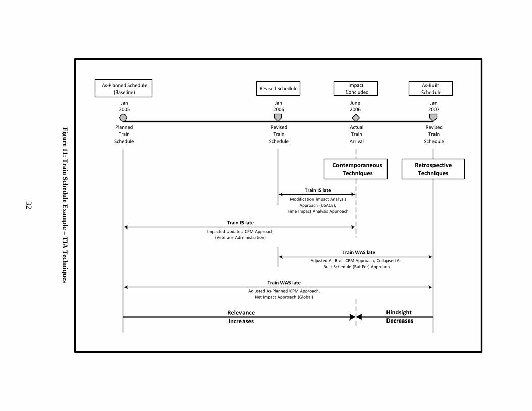
Figure 11: Train Schedule E
xample – T
IA T
echniques
32
As-Planned Schedule (Baseline) Revised Schedule Impact
Concluded As-Built Schedule
Jan
2005
Jan
2006
June 2006
Jan
2007
Planned
Train Schedule
Revised Train
Schedule
Actual Train
Arrival
Revised Train
Schedule
Contemporaneous Techniques
Retrospective Techniques
Train IS late
Modification Impact Analysis Approach (USACE),
Time Impact Analysis Approach
Train IS late Impacted Updated CPM Approach
(Veterans Administration)
Train WAS late Adjusted As-Built CPM Approach, Collapsed As-
Built Schedule (But For) Approach
Train WAS late
Adjusted As-Planned CPM Approach, Net Impact Approach (Global)
Relevance Increases
Hindsight Decreases

33
In January 2007, retrospective techniques will examine the impact of the June
2006 late train arrival. The Adjusted As-Planned and Net Impact approaches compare the
late arrival of the June 2006 train to the original planned train schedule, released in January
2005. According to this schedule, the train was late, which it was, yet the original
planned schedule is highly irrelevant compared to the revised schedule, released in January
2006. In addition to the irrelevancy of the schedule, perception of the event as it occurred is not
as accurate as if it were analyzed at the time of the event.
While the Adjusted As-Built and Collapsed As-Built (But-for) techniques use the revised
January 2006 schedule, they also use take a retrospective approach, analyzing the event in
January 2007. Doing so incorporates a final revised schedule that was not in existence in
June 2006, when the train arrived late.
Contemporaneous techniques will analyze the impact of the train being late at the
present date, June 2006. The first attempt at a contemporaneous approach, the Impacted
Updated (Veterans Administration) approach succeeds in analyzing the late arrival of the train, at
the time of the event. However, the technique does not require periodic revisions to the
schedule, or modifications to reflect the “as-built” schedule to date. The result is the use of
the original January 2005 planned schedule as means for analyzing if the train is late. It is
possible if, say, a train arrived late in February 2006, that this event would also be analyzed in
June 2006, because this method does not require updates and analysis for each delaying event.
The Modification Impact Analysis (U.S. ACOE) and Time Impact Analysis approaches are
contemporaneous techniques that analyze the actual train arrival in June
2006. Both techniques utilize the January 2006 revised train schedule, using the most
updated, relevant information. Although the Time Impact Analysis approach is
performed in January 2007, it determines the status of the train schedule in June 2006, as well as
the actual impact of the event at that time. As shown by the figure, when compared to the
previous approaches, the Modification Impact Analysis and Time Impact Analysis approaches
analyze the actual train arrival in June 2006 with the most relevant schedule, all while minimizing
hindsight. These methods give the most accurate analysis of when the train actually arrived in
June 2006, compared to the most recently schedule time of arrival.

34
Each method will now be described with accompanying diagrams, which follow
along with our drainage structure example, to illustrate how it is performed and how to
apportion responsibility. Start, finish, and duration of the as-planned, as-built, and
each delay activity are summarized in the following bar charts and table. Separate
activities represent each delay and its accompanying duration, such as in the case of
the owner’s late approval of the drawings. Although the duration of the activity Owner
Approve Drawings could have been extended to represent the ORD, making a separate
activity of each delay distinguishes each delay and aids in the schedule impact analysis
process. Owner Approve Drawings lasted for Day 1, followed in the CPM schedule by the
remaining duration of the activity, as was delayed, from Day 2 to Day 6.

35
As-Planned
Days 1 2 3 4 5 6 7 8 9 10 11 12 13 14 15 16 17 18
As-Planned (10 days)
Owner Approve Drawings
Excavate Soil
Install Drainage Structure
Backfill
8 days
As-Built As-Built (18 days)
Owner Approve Drawings
ORD: Drawing Approval
Excavate Soil
CRD: Missing Equipment
ED: Rain Delay
Install Drainage Structure
Backfill
Activity Duration As-Planned Start Finish
As-Built Start Finish
Owner Approve Drawings
1
1
1
1
1
Excavate Soil
4
1
4
1
4
Install Drainage Structure
6
3
8
11
16
Backfill 2 9 10 17 18
ORD: Drawing Approval 5 - - 2 6
CRD: Missing Equipment
4
-
-
3
6
ED: Rain Delay 5 - - 6 10
Figure 12: Drainage Structure Example Bar Chart and Delays

36
As-Planned / As-Built Schedule
Delaying Event
Completed Event at Time of Update 5.1.1 Retrospective Methods
Figure 13: Diagram Key
5.1.1.1 Global Impact Approach
Delay claims and time extension requests are not always put together in a
calculated and precise manner, as exemplified by the global impact approach to schedule
impact analysis. A claimant’s initial request for time extensions, usually during the
construction phase, ignores essential elements of scheduling. This approach lacks
serious analysis and may lead one to believe that the claimant is not serious about the
request.
The method involves plotting all delays, disruptions, and similar occurrences, of
which the claimant is not accountable for, on an as-built bar chart. Start and finish
dates of each event are determined, which follows by a calculation of total delay.
The total delay to the project is the sum of the durations of all delaying events. Using
the drainage structure example, Figure 14 shows the global impact approach method.
The as-built duration is completed in 18 days, 8 days later than the as-planned
duration. The contractor is making the claim for time extension, therefore
accounting only for excusable and owner-responsible delays. These delays are plotted
on the bar chart, showing the start, finish, and duration of each delay. Summing the
durations of these delays results in a request for a total time extension of 10 days.

37
Days
1 2 3 4 5 6 7 8 9 10 11 12 13 14 15 16 17 18
Step 1: Show As-Planned, As-Built, and all ORD & ED in bar chart format.
Time Extension = Sum of all delay durations
Time Extension = (5) + (5) = 10 days
As-Planned duration (10 days): As-Built duration (18 days): Owner and Excusable Delays:
ORD: Drawing Approval (5 days)
ED: Rain Delay (5 days)
Figure 14: Global Impact Approach
The contractor has ignored concurrency between the delaying events, simply summing
the durations of the delays. Two separate delays occurring during the same 9- day period should
not yield an extension of 10 days. An additional fault in this method is that there is no attempt
to analyze sequence of construction and how each delay affected the project completion. The
frequent result of this approach is a claim for time extensions that extend well beyond the
actual project delay [Bramble et al. 1990].
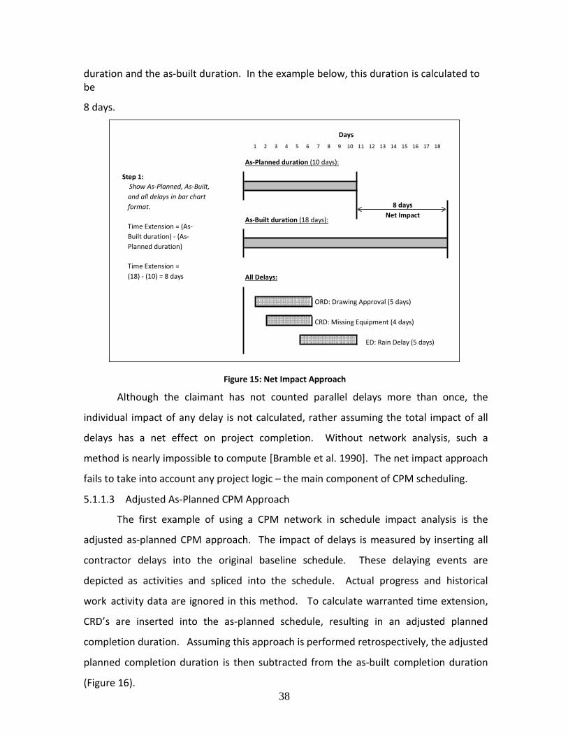
5.1.1.2 Net Impact Approach
The net impact approach attempts to account for the global impact approach’s failure to
assess concurrency through a technique that allegedly depicts only the net effect of all claimed
delays on a bar chart. In this method, all delays and disruptions, including those of the
contractor, are plotted on a bar chart, similarly as done in the global impact approach (Figure
15).
The figure below does show all three delays, yet, application of the net impact approach
will most likely be used when there are a large number of delaying events. The widespread
number of delays leads the claimant to argue that the only logical conclusion is that the
combined effect of these delays is the net delay on the entire project. Although the start, finish,
and duration of each delay are noted, their use is nonexistent. The contractor’s request for
time extension will be the difference between the as-planned
38
duration and the as-built duration. In the example below, this duration is calculated to be
8 days.
Days 1 2 3 4 5 6 7 8 9 10 11 12 13 14 15 16 17 18
Step 1: Show As-Planned, As-Built, and all delays in bar chart format.
Time Extension = (As-Built duration) - (As-Planned duration)
Time Extension = (18) - (10) = 8 days
As-Planned duration (10 days): As-Built duration (18 days): All Delays:
8 days Net Impact
ORD: Drawing Approval (5 days)
CRD: Missing Equipment (4 days)
ED: Rain Delay (5 days)
Figure 15: Net Impact Approach
Although the claimant has not counted parallel delays more than once, the
individual impact of any delay is not calculated, rather assuming the total impact of all
delays has a net effect on project completion. Without network analysis, such a
method is nearly impossible to compute [Bramble et al. 1990]. The net impact approach
fails to take into account any project logic – the main component of CPM scheduling.
5.1.1.3 Adjusted As-Planned CPM Approach
The first example of using a CPM network in schedule impact analysis is the
adjusted as-planned CPM approach. The impact of delays is measured by inserting all
contractor delays into the original baseline schedule. These delaying events are
depicted as activities and spliced into the schedule. Actual progress and historical
work activity data are ignored in this method. To calculate warranted time extension,
CRD’s are inserted into the as-planned schedule, resulting in an adjusted planned
completion duration. Assuming this approach is performed retrospectively, the adjusted
planned completion duration is then subtracted from the as-built completion duration
(Figure 16).

39
In our example, the lone CRD of 4 days is inserted into the as-planned CPM
schedule, leading to an adjusted completion duration of 14 days. The
adjusted completion is then subtracted from the as-built duration to determine the
amount of time extension warranted to the contractor. The contractor is awarded a 4-
day time extension. The theory is that the contractor is taking responsibility for their
delays, so the difference
between the adjusted completion and as-built completion is not their fault.
Days 1 2 3 4 5 6 7 8 9 10 11 12 13 14 15 16 17 18
As-Planned (10 days):
Owner Approve Drawings
Excavate Soil
Install Drainage Structure
Backfill
Step 1:
Adjusted Completion (14 days):
4 days
Insert CRD into As-Planned. Owner Approve Drawings
Contractor's Liability = Excavate Soil (Adjusted Completion duration) - (As-Planned duration) CRD: Missing Equipment
Contractor's Liability = Install Drainage Structure (14) - (10) = 4 days
Backfill
Step 2: Time Extension = (As-Built duration) - (Adjusted Completion duration)
Time Extension = (18) - (14) = 4 days
As-Built duration (18 days):
4 days
Figure 16: Adjusted As-Planned CPM Approach
The downfall with this method is that it ignores the actual construction progress and utilizes a
theoretical schedule. It is possible that the original plan was unworkable and unrealistic, and
may not have been followed. Furthermore, delays may have changed the critical path on an
incremental basis [Bramble et al. 1990]. Without representation of

40
changes in a schedule, relying on a very outdated train schedule is useless when
looking back to determine if the train was late at some prior moment in time.
5.1.1.4 Adjusted As-Built CPM Approach
In a continuation of the adjusted as-planned CPM approach, the adjusted as-built
CPM approach attempts to use the actual progress history with what appears to be CPM
scheduling techniques. Activities linked in a network with restraints form an as-built
schedule for the entire project, with delaying events shown as distinct activities. The
critical path is determined only twice – once in the as-planned analysis and again at the
end of the project. Not always, but a good way to rig the system is for claimants to tie
the delaying events to what they identify as the “critical path.”
As shown in Figure 17, an as-built CPM network is developed by inserting
ORD’s and ED’s into the as-planned schedules, along with logical constraints. Rather
than simply comparing the adjusted completion to the as-built completion date, this
method shows a “critical path,” attempting to hold the ORD’s and ED’s accountable for
the delayed completion of the project. In our example, subtracting the adjusted
completion duration from the as-built CPM network yields a time extension of 4 days.

41
Days
1 2 3 4 5 6 7 8 9 10 11 12 13 14 15 16 17 18
As-Planned duration (10 days):
4 days
Step 1: Contractor's Liability = Contractor's Liability from Adjusted As-Planned CPM Approach = 4 days
Step 2:
From Adjusted As-Planned CPM Approach…
Adjusted Completion duration (14 days): Adjusted As-Built (18 days):
4 days
Insert ORD & ED into As-Built. Owner Approve Drawings
Time Extension = ORD: Drawing Approval (Adjusted As-Built duration) - (Adjusted Completion duration) Excavate Soil
Time Extension = ED: Rain Delay (18) - (14) = 4 days
Install Drainage Structure
Backfill
Figure 17: Adjusted As-Built CPM Approach
The calculation of the critical path is somewhat manufactured, since it is a one-
time, after-the-fact calculation, rather than a contemporaneous analysis of the impact of
each delay, at the time of the delay. CPM scheduling is intended to be a forward-looking
technique used to predict the end of the job, not a method to establish the past; “CPM
Schedule” and “as-built” are contradictory terms. When claimants use this
technique, they generally will show only delays that are not their responsibility. They
may acknowledge their delays on the as-built schedule in a way that appears the delays
were not critical. Most importantly, no thorough effort is made to determine the
individual impact of each delay on project completion [Bramble et al. 1990].
5.1.1.5 Collapsed As-Built Schedule (But-for) Approach
The collapsed as-built schedule impact approach utilizes the “but-for” technique.
The owner and excusable delays are removed from the as-built schedule, “collapsing”
the schedule, and demonstrating “but-for” the owner and excusable delays, the project
would

42
have been completed in a timely fashion. The technique is performed in multiple steps
(Figure 18).
1. Once construction is complete, develop an as-built CPM schedule.
2. Remove ORD’s from the as-built CPM schedule.
3. The remaining duration represents what it would have been but-for
the owner’s delays.
4. Subtract the “but-for the owner’s delays” duration from the as-built
duration; the resulting days are solely the fault of the owner, warranting x
amount of days of delay damages and time extension.
5. Remove ED’s from the schedule. The resulting schedule is what would have
been had it not been for owner and excusable delays. The difference
between this and the previous schedule is all attributed to the excusable
delay – justification for y amount of days time extension. Using the formula
shown in the figure below, quantify the impact of the contractor by solving
for “Contractor’s Liability.”
6. Tally results from all steps.

43
Days
1 2 3 4 5 6 7 8 9 10 11 12 13 14 15 16 17 18
As-Built (18 days):
Owner Approve Drawings
ORD: Drawing Approval
Excavate Soil
CRD: Missing Equipment
ED: Rain Delay
Install Drainage Structure
Backfill
Step 1:
But-for ORD (18 days): 0 days
Remove ORD from As-Built. Owner Approve Drawings
Owner's Liability = Excavate Soil (As-Built duration) - (But-for ORD duration) CRD: Missing Equipment
Owner's Liability = ED: Rain Delay (18) - (18) = 0 days Time Extension Install Drainage Structure
Backfill
Step 2:
But-for ORD & ED (14 days): 4 days
Remove ED from But-for ORD. Owner Approve Drawings
Time Extension = Excavate Soil (But-for ORD & ED duration) - (But-for ORD duration) CRD: Missing Equipment
Time Extension = Install Drainage Structure (18) - (14) = 4 days
Backfill
Step 3: Apportion Contractor's Liability:
(As-Planned) + (Contractor's Liability) + (Owner's Liability) + (Time Extension) = (As-Built)
10 + (Contractor's Liability) + 0 4 = 18
Contractor's Liability = 4 days
Figure 18: Collapsed As-Built Schedule (But-for) Approach

44
The collapsed (but-for) logic relies on the presumption of a hypothetical outcome
from what the analyst says would have happened, had a portion of historical events not
occurred. This method places too much weight on theoretical situation, not giving
enough attention to cause and effect relationships. In addition, construction
scheduling should reflect the schedule in light of current situations and cumulative
events, not a retrospective subtraction of events is performed on a one time basis
[Bramble et al.
1990].
5.1.2 Contemporaneous Methods
5.1.2.1 Impacted Updated CPM (Veterans Administration) Approach
Another approach to schedule impact analysis is the impacted updated CPM
method, used by the Veterans Administration. The original project schedule, as updated,
is used to measure delay. The analysis will take place often during the course of
construction rather than after the project is complete. However, if the update
information still exists, the technique may be applied after project completion. Each
delaying event, not at the fault of the contractor, is analyzed to define where it should
be inserted into the schedule. These delays are inserted into the currently updated and
approved network diagram, as shown by Figure 19. Revisions to successive activities
caused by the delay or change are determined by comparing the schedules before and
after the changes have been incorporated. The effect that a delay or change has on the
CPM schedule is determined by a comparison of the schedules before and after the
delaying events are incorporated into the CPM Network; and only if the project
completion is extended, the contractor is entitled to a time extension [Veterans
Administration 1989]. In the event of concurrent delays, a single analysis must be made
for all delaying events, rather than making separate calculations for each change.
Our example consists of concurrently delaying events, an ORD and ED, which are
inserted into the most recently approve schedule, the original as-planned schedule.
The result is an adjusted completion of 18 days, 8 days longer than the as-planned.
The 8 days will be granted as a time extension.

45
Days
1 2 3 4 5 6 7 8 9 10 11 12 13 14 15 16 17 18
Step 1:
Updated Schedule of Record (10 days):
Schedule of Record is updated Owner Approve Drawings to time of delaying events.
Schedule of Record is updated to
Excavate Soil
beginning of the delays, Install Drainage Structure which began on day 2.
Backfill
Step 2:
Adjusted Completion (18 days):
8 days
Insert ORD & ED into Updated Owner Approve Drawings Schedule of Record.
Time Extension =
ORD: Drawing Approval
(Adjusted Completion duration) - Excavate Soil (Schedule of Record duration)
Time Extension =
ED: Rain Delay
(18) - (10) = 8 days Install Drainage Structure
Backfill
Figure 19: Impacted Updated CPM (Veterans Administration) Approach
This approach analyzes all delays that have occurred since the last update at one
time, assuming that the project schedule, as updated and approved, is correct. It does
not determine whether actual construction in the field differs from the approved
schedule. This is another method that fails to properly use the CPM approach in a
contemporaneous manner by updating after each delay [Bramble et al. 1990].
5.1.2.2 Modification Impact Analysis (U.S. Army Corps of Engineers’) Approach
The U.S. Army Corps of Engineers’ Modification Impact Evaluation Guide
directs another method of schedule impact analysis. This approach can be broken down
into three steps:
Step 1: The time impact analyst determines the actual status of the job when
each owner or excusable delay occurred, without influence from
the contractor’s formal project schedule. This eliminates situations
where the contractor’s real plan may not be the same as indication in
the schedule, or the schedule may not have been revised to reflect
the effects of previous modifications.

46
Step 2: The effects of modifications or delay-causing events should be
evaluated to determine which ensuing changes to the schedule must be
made to accommodate these events. New activities may need to be
created if all or part of the work does not fit into an existing activity.
Step 3: The schedule as revised is used for new calculations to determine the
new critical path and project completion date. From this new completion
date, time extensions and or delay damages can be granted.
Figure 1 evaluates the drainage structure example using the modification impact
analysis method. Analysis of Delay 1, the owner’s failure to approve drawings in time,
begins with an updated as-built schedule at the start of the ORD (day 2). The ORD is
then inserted into the schedule, making the proper modifications in the network to
accommodate the change. Because the ORD is on the critical path, the result is
the project being extended to a completion date of 14 days, granting 4 days of time
extension and owner liability to the contractor. Delay 2, the 5 days of unexpected
severe rain, starts on day 6 and last until day 10. Although the inclimate weather event
is 5 days, the completion of the project is pushed back only 4 days, since this event is
concurrent with the owner’s untimely approval of the shop drawings. The critical path
shifted from the owner’s delay to that of the excusable delay. The result is granting 4
days time extension to the owner. The total time extension granted is 8 days, along with
4 days of owner liability.

47
Owner Approve D
Excav
DELAY #1:
Days
1 2 3 4 5 6 7 8 9 10 11 12 13 14 15 16 17 18
Step 1:
Updated Schedule of Record (10 days):
Actual status of job is reflected Owner Approve Drawings in an updated Schedule of Record.
Schedule of Record is updated to
Excavate Soil
beginning of first delay, ORD, Install Drainage Structure which began on day 2.
Backfill
4 days
Step 2: Insert delay and create Modified Schedule of Record.
Owner's Liability = (Modified SoR duration) - (Updated SoR duration)
Owner's Liability =
Modified Schedule of Record (14 days):
rawings
ORD: Drawing Approval
ate Soil
Install Drainage Structure
(14) - (10) = 4 days Backfill Time Extension

48
DELAY #2:
Days
1 2 3 4 5 6 7 8 9 10 11 12 13 14 15 16 17 18
Step 1:
Updated Schedule of Record (14 days):
Actual status of job is reflected Owner Approve Drawings in an updated Schedule of Record.
Schedule of Record is updated to
ORD: Drawing Approval
beginning of third delay, ED, Excavate Soil which began on day 6.
Install Drainage Structure
Backfill
4 days
Step 2:
Modified Schedule of Record (18 days):
Insert delay and create Modified Owner Approve Drawings Schedule of Record.
Time Extension =
ORD: Drawing Approval
(Modified SoR duration) - Excavate Soil (Updated SoR duration)
Time Extension =
ED: Rain Delay
(18) - (14) = 4 days Install Drainage Structure
Backfill
Figure 20: Modification Impact Analysis (U.S. Army Corps of Engineers’) Approach
Particular to this method is that a schedule revision is required for each modification, ensuring
that the project status is known and future changes predicted at the time of each possible
delaying event. Adjustments to the schedule and impact analysis shall be performed at or near
the time of the delay, not at the completion of the project. If there are no modifications or
owner-caused delays or disruptions, then the contractor is solely responsible for late completion
and is not warranted a time extension [Bramble et al. 1990].
5.1.2.3 Time Impact Analysis Approach
Of all the methods described, the time impact analysis method is the most comprehensive,
incorporating the actual project history into a dynamic plan. Any delay, change, or disruption to
the schedule calls for time impact analysis to isolate and quantify the event. To do so, a
“picture” of the CPM network is taken when the event occurs, followed by inserting the
change into the network. All variations that may occur in the

49
Owner Approve D
Excav
schedule – such as the critical path may shift, float may be consumed, or new links between
activities may be required – are analyzed to determine what the effect of the event is. Any
additional or revised activities will be reflected in the as-built schedule.
In the example below, Delay 1 is the owner’s failure to approve the drawings on time
(ORD). The schedule is updated to the beginning of the delay, day 1, the delay is spliced into
the CPM network, and the adjusted completion duration is determined to be
14 days. These 4 days, the fault of the owner, are awarded as delay damages and time
extension. On day 3, the contractor is unable to have the proper equipment on site to
install the drainage structure, which shifts the critical path onto this CRD, resulting in an adjusted
completion date of day 14. Because the completion date did not change, the contractor is not
liable for any delay resulting from this event. Inclimate weather, Delay
3, further prevents the drainage structure from being installed. Once again, the critical path
shifts, this time from the CRD to the ED, extending project completion an additional
4 days to day 18. These 4 days, because they are an excusable delay, are awarded as a time
extension. The sum of damages and extensions are 8 days time extension, 4 days
delay damages, and 0 days liquidated damages.
DELAY #1: Days 1 2 3 4 5 6 7 8 9 10 11 12 13 14 15 16 17 18
Step 1:
Updated Schedule of Record (10 days):
Actual status of job is reflected Owner Approve Drawings in an updated Schedule of Record.
Schedule of Record is updated to
Excavate Soil
beginning of first delay, ORD, Install Drainage Structure which began on day 2.
Backfill
4 days
Step 2: Insert delay and create Modified Schedule of Record.
Owner's Liability = (Modified SoR duration) - (Updated SoR duration)
Owner's Liability =
Modified Schedule of Record (14 days):
rawings
ORD: Drawing Approval
ate Soil
Install Drainage Structure
(14) - (10) = 4 days Backfill Time Extension

50
DELAY #2:
Days
1 2 3 4 5 6 7 8 9 10 11 12 13 14 15 16 17 18
Step 1:
Updated Schedule of Record (14 days):
Actual status of job is reflected Owner Approve Drawings in an updated Schedule of Record.
Schedule of Record is updated to
ORD: Drawing Approval
beginning of second delay, CRD, Excavate Soil which began on day 3.
Install Drainage Structure
Backfill
Step 2:
Modified Schedule of Record (14 days): 0 days
Insert delay and create Modified Owner Approve Drawings Schedule of Record.
Contractor's Liability =
ORD: Drawing Approval
(Modified SoR duration) - Excavate Soil (Updated SoR duration)
Contractor's Liability =
CRD: Missing Equipment
(14) - (14) = 0 days Install Drainage Structure
Backfill

51
DELAY #3:
Days
1 2 3 4 5 6 7 8 9 10 11 12 13 14 15 16 17 18
Step 1:
Updated Schedule of Record (14 days):
Actual status of job is reflected Owner Approve Drawings in an updated Schedule of Record.
Schedule of Record is updated to
ORD: Drawing Approval
beginning of third delay, ED, Excavate Soil which began on day 6.
CRD: Missing Equipment
Install Drainage Structure
Backfill
Step 2:
Modified Schedule of Record (18 days):
4 days
Insert delay and create Modified Owner Approve Drawings Schedule of Record.
Time Extension =
ORD: Drawing Approval
(Modified SoR duration) - Excavate Soil (Updated SoR duration)
Time Extension =
CRD: Missing Equipment
(18) - (14) = 4 days ED: Rain Delay
Install Drainage Structure
Backfill
Figure 21: Time Impact Analysis Approach
The goal of the systematic time impact analysis approach is to give full
consideration to the actual effect of events individually and acting together, and to
evaluate the effect of ongoing delays. The goal of the method is to examine the
evolution of the critical path and the impact of delaying events on that path [Bramble et
al. 1990]. The time impact analysis approach is often the most time-consuming delay
analysis method; however, it can be very accurate, has the potential to be the least
controversial and most analytical, and can be equitable to all parties [Stumpf 2000].
5.2 Comparison of Methods
Figure 22 tabulates the results of each schedule impact analysis technique as
applied to the drainage structure example. Although certain techniques apportion
“owner liability” and “contractor liability”, the focus is rather on determining what
time extension, if any, the contractor is entitled to for delays.
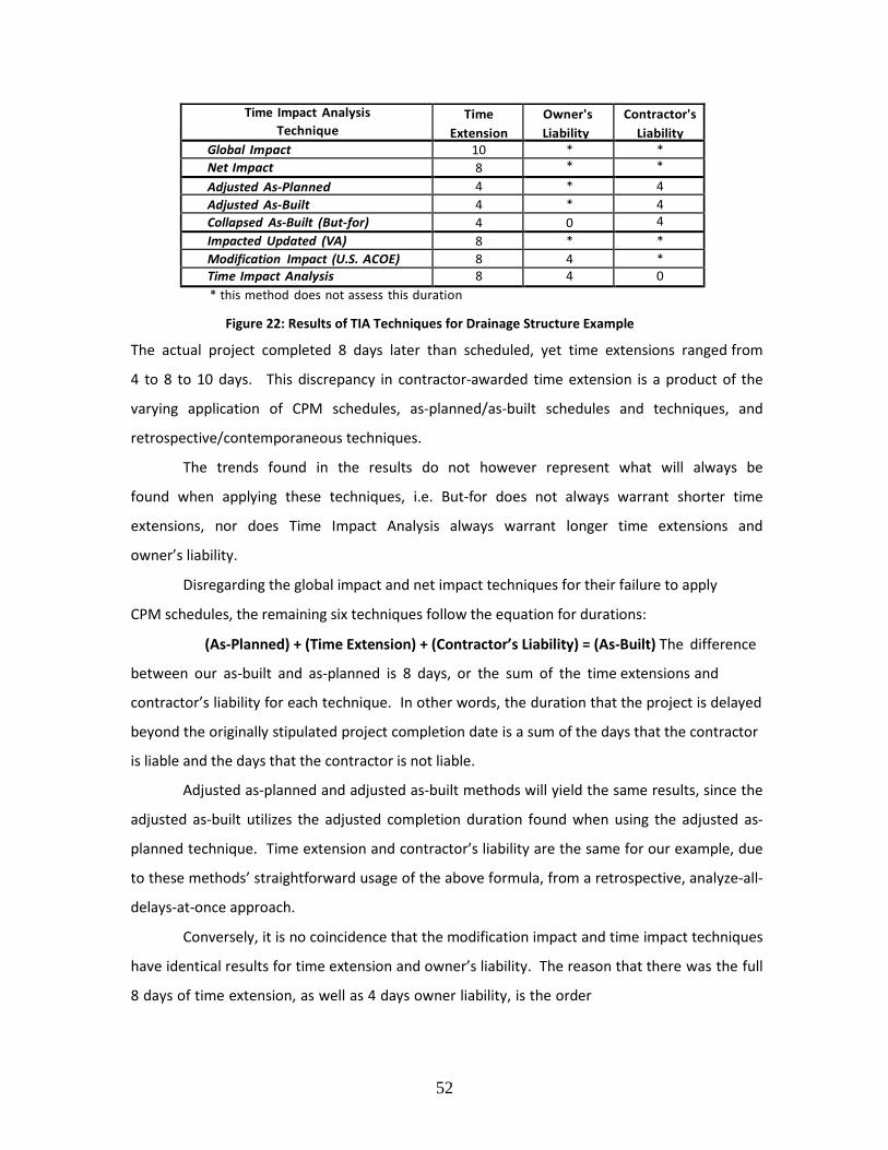
52
Time Impact Analysis Technique
Time Extension
Owner's Liability
Contractor's Liability
Global Impact 10 * * Net Impact 8 * * Adjusted As-Planned 4 * 4 Adjusted As-Built 4 * 4 Collapsed As-Built (But-for) 4 0 4 Impacted Updated (VA) 8 * * Modification Impact (U.S. ACOE) 8 4 * Time Impact Analysis 8 4 0 * this method does not assess this duration
Figure 22: Results of TIA Techniques for Drainage Structure Example
The actual project completed 8 days later than scheduled, yet time extensions ranged from
4 to 8 to 10 days. This discrepancy in contractor-awarded time extension is a product of the
varying application of CPM schedules, as-planned/as-built schedules and techniques, and
retrospective/contemporaneous techniques.
The trends found in the results do not however represent what will always be
found when applying these techniques, i.e. But-for does not always warrant shorter time
extensions, nor does Time Impact Analysis always warrant longer time extensions and
owner’s liability.
Disregarding the global impact and net impact techniques for their failure to apply
CPM schedules, the remaining six techniques follow the equation for durations:
(As-Planned) + (Time Extension) + (Contractor’s Liability) = (As-Built) The difference
between our as-built and as-planned is 8 days, or the sum of the time extensions and
contractor’s liability for each technique. In other words, the duration that the project is delayed
beyond the originally stipulated project completion date is a sum of the days that the contractor
is liable and the days that the contractor is not liable.
Adjusted as-planned and adjusted as-built methods will yield the same results, since the
adjusted as-built utilizes the adjusted completion duration found when using the adjusted as-
planned technique. Time extension and contractor’s liability are the same for our example, due
to these methods’ straightforward usage of the above formula, from a retrospective, analyze-all-
delays-at-once approach.
Conversely, it is no coincidence that the modification impact and time impact techniques
have identical results for time extension and owner’s liability. The reason that there was the full
8 days of time extension, as well as 4 days owner liability, is the order

53
in which delays took place on the project. The beginning of each delay marks which delay
rules in a situation where there are concurrent delays. Because the owner was not going to be
able to approve the drawings for an extra 5 days, this created 4 days of float in which the
contractor was unable to provide the proper equipment to install the drainage structure.
The modification impact and time impact methods are one in the same, except for that
the modification impact does not assess contractor’s liability. The reason for this is that once
determining inserting a delay and updating the CPM schedule, the modification impact analysis
requires the analyst to “note any slippage of final completion date [and the] difference is
amount of time extension justified because of impact” [Department of the Army 1979]. No
mention is given to awarding damages to the contractor or assigning contractor’s responsibility.
For this reason, it is assumed that this method was not intended to be used to award contractors
damages. However, the method is nearly identical to that of the time impact analysis
technique, and if contractor delays were considered in analysis, contractor’s liability could easily
be assessed.
6 SUMMARY AND RECOMMENDATIONS
Each project starts with a plan – the what, how, where and in what order – of the matter
in which work will be completed. The plan is then given greater detail – the who and when –
that develop the baseline schedule, or the contractor’s original understanding and plan of
action for the project. Once the project commences, schedule updates and revisions –
whether at scheduled intervals or as result of a change – create new schedules of record that
shall meet the owner’s approval. Eventually, the final schedule of record will be the as-built
schedule – a final documentation of actual starts and finishes of activities, any delays, change
orders, extra work, weather, and other factors that affected project completion.
Events that influence project completion are of various type, including delays,
disruptions, change, suspension, and termination. One of three parties is responsible for these
sources of schedule impact: the owner, the contractor, or a third party not to be at fault of the
owner or contractor. When classifying delays, those caused by a third party, such as unusually
severe weather, are “excusable delays” and warrant time extensions to the contractor. Owner
responsible delays are “compensable” delays, and in addition to rewarding the contractor time
extension, may involve delay damages. On the other hand, when the contractor is responsible
for a delay, it is a “non-excusable delay”, and not only is the contractor declined a time
extension, but they may also be held accountable for liquidated damages.

54
These different types of delay do not always take place independently of each other –
“concurrent delays” happen at the same time and/or on separate parallel paths of the CPM
network. As shown by the drainage structure example, properly apportioning responsibility
and awarding time extensions and/or damages for delays, even for a very simple example,
requires more than a rudimentary process.
Each of the eight time impact techniques as described in full detail give an overview of
how each is applied, its strengths, and in many cases, its weaknesses. The comparison of time
impact methods emphasizes using the most relevant, updated, and revised schedule, while
minimizing hindsight – a contemporaneous method based on the as-built schedule that is a true
representation of the actual project. Such a formula is considered the most comprehensive and
accurate means for determining the impact that delaying events have on the schedule and
project completion.
This document recommends the use of the modification impact analysis
technique, as described by the U.S. Army Corps of Engineers’ Modification Impact Evaluation
Guide, which is summarized in three steps:
1. Determine the actual status of the job when the delay occurred
2. Analyze the scope of the modification to determine which activities will be
directly affected, and modify schedule to accommodate affected activities
3. Use revised schedule to determine new critical path and completion date,
which may issue a time extension and/or damages.
Although the modification impact analysis technique is preferred, if evaluation of the delaying
event cannot be performed at the time of the delaying event, use the time impact analysis
technique to go back to the schedule that would have existed at the time of the delaying event.
This technique is nearly identical to that of the modification impact technique, only differing in
that it recreates an “updated” schedule that most closely reflects the actual status of the job
when the delay occurred, retrospectively creating a contemporaneous “snapshot” of the project
at the beginning of the delaying event. The advantages of these preferred techniques
over all others described are that the modification impact and time impact analyses use
the most recently updated, relevant schedules and project information, at the time of delay,
reducing hindsight that can be created when evaluating claims well after pertinent
events have taken place.

55
7 REFERENCES
Barba-Arkhon International, Inc. (1996). “Schedule Delay and Loss of Productivity Analysis: Schedule float (who owns it?)”
Bartholomew, S.H. Construction Contracting: Business and Legal Principles. Second
Edition. Upper Saddle River, New Jersey: Prentice Hall, 2002.
Bramble, B.B. and Callahan, M.T. Construction Delay Claims. Third Edition. New York: Construction Law Library, Aspen Publishers, 2000.
Bramble, B.B., D’Onofrio, M.F., and Stetson, J.B. Avoiding & Resolving Construction
Claims. Kingston, Massachusetts: R.S. Means Co., 1990.
Clough, R.H., Sears, G.A., and Sears, S.K., Construction Project Management. Fourth Edition. New York: John Wiley & Sons, 2000.
de la Garza, J.M. CEE 5010: Schedule Impact Analysis Course Notes. Virginia
Polytechnic Institute and State University, Spring 2006.
Hildreth, J.C. CEE 4024: Construction Control Techniques Course Notes. Virginia Polytechnic Institute and State University, Fall 2005. Ho, A.C.
“Schedule Delay Impact Analysis.” Knoke, J.R. and Jentzen, G.H.“Developing an As-Built Schedule From Project
Records.” Transactions of AACE International, 1996.
Kraiem, Z.M. and Diekmann, J.E. “Concurrent Delays in Construction Projects.” Journal of Construction Engineering and Management. Vol. 113, No. 4, pages 591-602, December 1987.
Munoz, B. “An Introduction to the Management Principles of Scheduling.” VDOT-VT Partnership for Project Scheduling,
May 2005.
Parvin, C.M. Transportation Construction Claims & Disuptes: Causes, Prevention, Resolution. Richmond, Virginia: P&W Publications, Inc., 1993.
Schumaker, L. “Quantifying and Apportioning Delay on Construction Projects.” Cost
Engineering. Vol. 37, No. 2, page 11, February 1995.
Stumpf, G.R. “Schedule Delay Analysis.” Cost Engineering. Vol. 42, No. 7, pages 32-43, July 2002.
US Army Corps of Engineers. "Modification Impact Guide EP415-1-3." Department of the Army, Office of the Chief of Engineers, July 1979.
Veterans Administration. “VA CPM Handbook.” Veterans Administration, 1989.
Virginia Department of Transportation. Road and Bridges Specifications. Richmond, Virginia, 2002.
Wickwire, J.M., Driscoll, T.J., Hurlbut, S.B., and Hillman, S.B. Construction Scheduling: Preparation, Liability, and Claims.
Second Edition. New York: Construction Law Library, Aspen Publishers, 2003.
Wideman, M. “Wideman Comparative Glossary of Project Management Terms v3.1.” <http://www.maxwideman.com/pmglossary/PMG_B01.htm>, 2006.
Winter, R. "Checks and Balances: Baseline Schedule Review." Ron Winter Consulting.
<http://www.ronwinterconsulting.com/rabaseline.htm>, October 2002.